test a wr31 router - digi international
TRANSCRIPT

Test a WR31 Router How to test a WR31 router step by step.
Technical Support
December 2018

Contents
1 Introduction ......................................................................................................................................... 3
1.1 Outline .......................................................................................................................................... 3
1.2 Assumptions ................................................................................................................................. 3
1.3 Corrections ................................................................................................................................... 3
1.4 Version .......................................................................................................................................... 3
2 Physical Configuration ......................................................................................................................... 4
2.1 Equipment Required .................................................................................................................... 4
2.1.1 Diagram .................................................................................................................................... 5
3 Step by Step Instructions ..................................................................................................................... 6
3.1 Install FlashWriter ........................................................................................................................ 6
3.2 Download the .ALL file: ................................................................................................................ 6
3.3 Make the initial connections ........................................................................................................ 6
3.4 Launch FlashWriter ...................................................................................................................... 7
3.5 Reviewing Flashwriter error messages...................................................................................... 16
4 Check LEDs ......................................................................................................................................... 17
5 Check W-WAN connectivity ................................................................................................................ 18
5.1 Test SIM detection switch .......................................................................................................... 18
5.2 Test SIM 1 .................................................................................................................................... 19
5.3 Test SIM 2 .................................................................................................................................... 21
6 Check W-WAN Signal Strength ........................................................................................................... 23
7 Check USB ports ................................................................................................................................. 24
8 Check ETH ports 1 and 2 .................................................................................................................... 25
9 Check Serial ports .............................................................................................................................. 26

How to test a WR31 router step by step.
Page | 3
1 INTRODUCTION
1.1 Outline
Should it happen that the boot loader becomes corrupted on a WR31 product, it is possible for an end
user to re-load the boot loader by following this guide.
The symptoms of a corrupted boot loader are usually as follows. When applying the power, the only
LED to illuminates is the power LED. It is also possible that other “unusual” LED patterns may occur
depending upon how “damaged” the boot loader is.
1.2 Assumptions
This guide has been written for use by technically competent personnel with a good understanding of
the communications technologies used in the product and of the requirements for their specific
application.
This quick note applies only to:
Model: Digi Transport WR31
1.3 Corrections
Requests for corrections or amendments to this documentation are welcome and should be
addressed to: [email protected]
Requests for new quick notes can be sent to the same address.
1.4 Version Version Number Status
0.1 Draft
1.0 Completed 15.03.2016
1.1 Module list update

How to test a WR31 router step by step.
Page | 4
2 PHYSICAL CONFIGURATION
2.1 Equipment Required
A PC running a Microsoft Windows TM based operating system.
1. A PC connected to the Internet running a Microsoft Windows TM operating system with a built
in serial comm. port. (USB to serial adaptors do not work well.)
2. A 9-way “straight through” serial cable to connect the PC directly to the WR31.
3. A “USB A to USB A” cable to connect the PC directly to the WR31. (No mistake, A to A)
4. An Ethernet switch/hub to connect the PC to the WR31 (usually your normal office Ethernet
switch/hub will be fine if there is a spare port)
5. CAT 5 cables to connect the WR31 and PC to the Ethernet switch.

How to test a WR31 router step by step.
Page | 5
2.1.1 Diagram
The following diagram represents how the equipment will be connected during the repair process:
The internet connection is not essential but may be useful during troubleshooting. It is essential that
the PC’s Ethernet communication interface is configured correctly (e.g. it has an IP address)
Also note that the Ethernet switch/hub used must have spanning tree protocol disabled.

How to test a WR31 router step by step.
Page | 6
3 STEP BY STEP INSTRUCTIONS
3.1 Install FlashWriter
Install the latest version of FlashWriter from the following link:
http://ftp1.digi.com/support/firmware/FlashWriter.msi
3.2 Download the .ALL file:
Download the following zip file to your PC and extract all the contents to a single folder
http://ftp1.digi.com/support/firmware/transport/flashwriter/latest/wr31-flashwriter-x.x.x.x.zip
Click: http://ftp1.digi.com/support/firmware/transport/flashwriter/latest/
where X.X.X.X is the current firmware version.
Open the .ini file extracted and add the following text to the second line (be sure to include
the comma at the end).
bootimx28,
3.3 Make the initial connections
1. Connect the “straight-through” serial cable between the PC and the “Serial 0” on the WR31. 2. Connect the WR31’s Ethernet (LAN 0) port to your “office network”.
3. Ensure the PC is also connected to the same “office network”
4. Connect one end of the “USB A to USB A” lead to your PC. Do NOT connect to the other end to the WR31 yet.

How to test a WR31 router step by step.
Page | 7
3.4 Launch FlashWriter
Launch Flashwriter from the start menu. Select the communications port number (PC comm. port
number) to which the WR31 is connected. (On most PC’s with a built in serial port, this will be “1” OR
“2”. Leave the other settings at their default values (TFTP and Event driven mode ONLY ticked):
Click Load
If your PC has more than one network adapter, be sure to select the one that represents the
connection to “Office Network” illustrated in 0.
If your PC only has a single network adapter this screen will not appear:

How to test a WR31 router step by step.
Page | 8
In the file dialogue, select the “ALL” file you extracted from the ZIP earlier:
And click “Open”.

How to test a WR31 router step by step.
Page | 9
The following message will appear:
It is critical that the correct selection is made at this point.
Note 1: Since FlashWriter version 1.0.525 characters 6 and 7 are included in the W-WAN module name,
see above.
Note 2: characters 6 and 7 of the part number (SKU) on the approval label. In the example below these
are “L1”:

How to test a WR31 router step by step.
Page | 10
Refer to the following table to determine which selection to make:
Characters 6 & 7 Flashwriter Selection
00 100 No module
G1 5 Cinterion/Siemens MC75i/TC63i/MC75/Triorail
E1 5 Cinterion/Siemens MC75i/TC63i/MC75/Triorail
H0 9 Option HSDPA/HSUPA modules
H1 9 Option HSDPA/HSUPA modules
H2 9 Option HSDPA/HSUPA modules
C0 10 CMotech CDMA module
C1 11 Sierra Wireless CDMA module
C2 11 Sierra Wireless CDMA module
C3 10 CMotech CDMA module
C4 10 CMotech CDMA module
C6 10 CMotech CDMA module
C7 10 CMotech CDMA module
U0 9 Option HSDPA/HSUPA modules
U1 9 Option HSDPA/HSUPA modules
U2 13 Ericsson F3507g/F3607gw/F3307/F5521gw HSDPA module
U3 7 Sierra Wireless 3G module
U4 13 Ericsson F3507g/F3607gw/F3307/F5521gw HSDPA module
U5 17 Gobi UMTS or 18 Gobi CDMA
U6 13 Ericsson F3507g/F3607gw/F3307/F5521gw HSDPA module
U7 13 Ericsson F3507g/F3607gw/F3307/F5521gw HSDPA module
U8 17 Gobi UMTS
U9 24 Telit 3G
L1 28 Huawei LTE
L2 23 Novatel LTE
L3 23 Novatel LTE
L4 26 Sierra Wireless 4G/LTE module
L5 26 Sierra Wireless 4G/LTE module
L6 29 Telit LTE Version 1
L7 29 Telit LTE Version 1
L8 29 Telit LTE Version 1
L9 26 Sierra Wireless 4G/LTE module
M2 31 Cellient LTE
M3 32 Telit LTE Version 2
M4 29 Telit LTE Version 1
M5 32 Telit LTE Version 2
M6 32 Telit LTE Version 2
M7 32 Telit LTE Version 2
M8 26 Sierra Wireless 4G/LTE module
M9 29 Telit LTE Version 1

How to test a WR31 router step by step.
Page | 11
The next screen provides some complex instructions:
Please ignore that it might show WR21, all is correct.
The instructions are broken down below for extra clarity:
1. Using a thin screwdriver or a paperclip, keep the reset button pressed. Be careful to press soft, but firm.
2. Insert the power lead – note that this is a locking barrel connector. It needs to be aligned
carefully and then twisted to prevent it from coming detached.
3. Keep the reset button held in for 10 full seconds. (When you let go of the reset button there
should be no change of the LED status – if there is you have not held it in for long enough.)
4. Within 15 seconds, insert the USB lead (that already has the other end connected to the PC)
into the WR31. At this point the PC should detect the WR31 and may need to install some USB
drivers. Wait for the PC to do this. (If nothing happens on the PC, then it may be that the reset button was not held in for long enough, go back to step 1 and try again.)
5. Whilst the reset button is held, click OK in FlashWriter
6. If successful, you should be prompted to enter the 6 digit serial number. (Refer to the label
under the WR31 to find the serial number. Please ignore a leading ‘S’).
Please ensure that you enter the correct serial number as a wrong serial number would cause a wrong MAC-Address!

How to test a WR31 router step by step.
Page | 12
Click OK
7. If successful, you should be prompted to enter the hardware revision number. (Refer to the
label under the WR31 to find the correct hardware revision.)

How to test a WR31 router step by step.
Page | 13
Click OK

How to test a WR31 router step by step.
Page | 14
8. You should see the .sbios file start to load:
After programming in the W-WAN counter and other options, next the .ALL file will start to
load:
9. After reboot and checks, the following message should be displayed:

How to test a WR31 router step by step.
Page | 15
This means the WR31 has been successfully recovered.
10. Please remove the USB Cable when you have finished FlashWriter as it might disturb the
further testing procedure!
At this stage the following hardware components (and more) have been successfully tested:
FLASH
SDRAM
SRAM
ETHERNET 0
Serial port 0
Interface to radio module (if fitted)

How to test a WR31 router step by step.
Page | 16
3.5 Reviewing Flashwriter error messages
If during the previous session an error occurred, please check the table below for the recommended
course of action:
Error Message Recommendation
Failed to establish contact via the serial port, please try again.
This procedure is quite tricky so it is quite possible you did not get the timing quit correct. However if you can get passed this stage repeatedly on a known working WR31 and this particular WR31 always fails it must be faulty. Please create an RMA with reason Flashwriter IMX28 boot failed.
XModem TX failure on pre-loading bootloader.
Check that this repeatedly fails and that you can carry out the procedure correctly on a known working router. If so then please create an RMA with reason Flashwriter XModem TX failure on pre-loading bootloader.
XModem did not initialise! Check that this repeatedly fails and that you can carry out the procedure correctly on a known working router. If so then please create an RMA with reason Flashwriter XModem did not initialise!
sbios upload not confirmed by unit. Check that this repeatedly fails and that you can carry out the procedure correctly on a known working router. If so then please create an RMA with reason Flashwriter sbios upload not confirmed by unit.
Scan failed DO NOT remove power from unit.
Ignore the message, remove the power try again. Check that this repeatedly fails and that you can carry out the procedure correctly on a known working router. If so then please create an RMA with reason Flashwriter scan failed.
Error re-accessing bootloader, >> prompt not received after sending password.
Check that this repeatedly fails and that you can carry out the procedure correctly on a known working router. If so then please create an RMA with reason Error re-accessing bootloader, >> prompt not received after sending password.
Unit did not reboot successfully after loading bootloader.
Check that this repeatedly fails and that you can carry out the procedure correctly on a known working router. If so then please create an RMA with reason Flashwriter: Unit did not reboot successfully after loading bootloader.
Unable to start TFTP
Check that the Ethernet cable is connected correctly and the LAN LED is on. This error can often be “user error” or “network issues”. However if this error is repeatable on the suspected bad router but does not occur on a known good router then request an RMA with reason. “Flashwriter TFTP failed to start”
Blue progress bar moves, but slowly and with lots of re-tries and eventually fails.
This suggests a hardware problem or a network issue on your LAN. Check again that this works on a known good router, if it does and it still fails with this error on the suspected bad router then request an RMA with reason. “Flashwriter TFTP failed to complete”
Unable to communicate with device after reboot
Check to see if the router is continuously rebooting. Please contact Digi technical support for help.
W-WAN module failed check - please check you selected the correct module!
Be very careful to check that you are selecting the correct radio module when you launch FlashWriter. This is the number one cause of this error! If you are unsure of the type of radio module fitted open the case. If you are sure you are selecting the correct radio module and if this error is repeatable on the suspected bad router yet works fine on a known good router, please request an RMA with reason: “Flashwriter radio check failed.”

How to test a WR31 router step by step.
Page | 17
4 CHECK LEDS
Connect both Ethernet ports to a switch.
Access the CLI (Command Line Interface) – this can be achieved:
Through the serial port @115200 bps
Via a telnet or SSH connection
Via the “execute a command” page of the web user interface.
Issue the “flashleds” command and check that all LEDs are illuminated. If there is an LED fault please
request an RMA with code:
“x LED failure” where x is:
Power LED
SERVICE
WWAN
Signal III
Signal II
Signal I
SYSTEM
LAN 0
LAN 1
The upper Ethernet LED will only light if a working network cable is attached.

How to test a WR31 router step by step.
Page | 18
5 CHECK W-WAN CONNECTIVITY
5.1 Test SIM detection switch
With the router powered off, insert a SIM card into BOTH SIM slots of the WR31 and open the CLI
interface.
Access to the CLI (Command Line Interface) – this can be achieved:
Through the serial port @115200 bps
Via a telnet or SSH connection
Via the “execute a command” page of the web user interface.
Issue the following command:
simconn ?
This command tells you which SIM slots are populated and also the SIM that is currently in use. The
value before the comma is SIM 1 and the value after the comma is SIM 2. 1000 means that the SIM is present. 1001 means that the SIM is present and the active SIM. Here is a summary:
1 = SIM not present
1000 = SIM present 1001 = SIM present and connected
The output should be as follows:
simconn ? simconn: 1001,1000 OK
Showing that SIM 1 is present and active and SIM 2 is present.
If the SIM cards are physically inserted but do not show as present please request an RMA with reason
“SIM DETECTION FAIL”

How to test a WR31 router step by step.
Page | 19
5.2 Test SIM 1
Ensure that an antenna (or both if using an LTE unit) is connected and the router is located in an area
with good signal strength.
Navigate to:
Configuration - Network > Interfaces > Advanced > PPP 1 > Mobile
Change W-WAN SIM: from “Any” to “SIM 1”
Click Apply.
Next navigate to
Configuration - Network > Interfaces > Mobile
And select SIM 1
Under “Mobile Settings”
Enter the correct APN for the SIM card installed in slot 1
Click Apply.
How to test a WR31 router step by step.
Page | 20
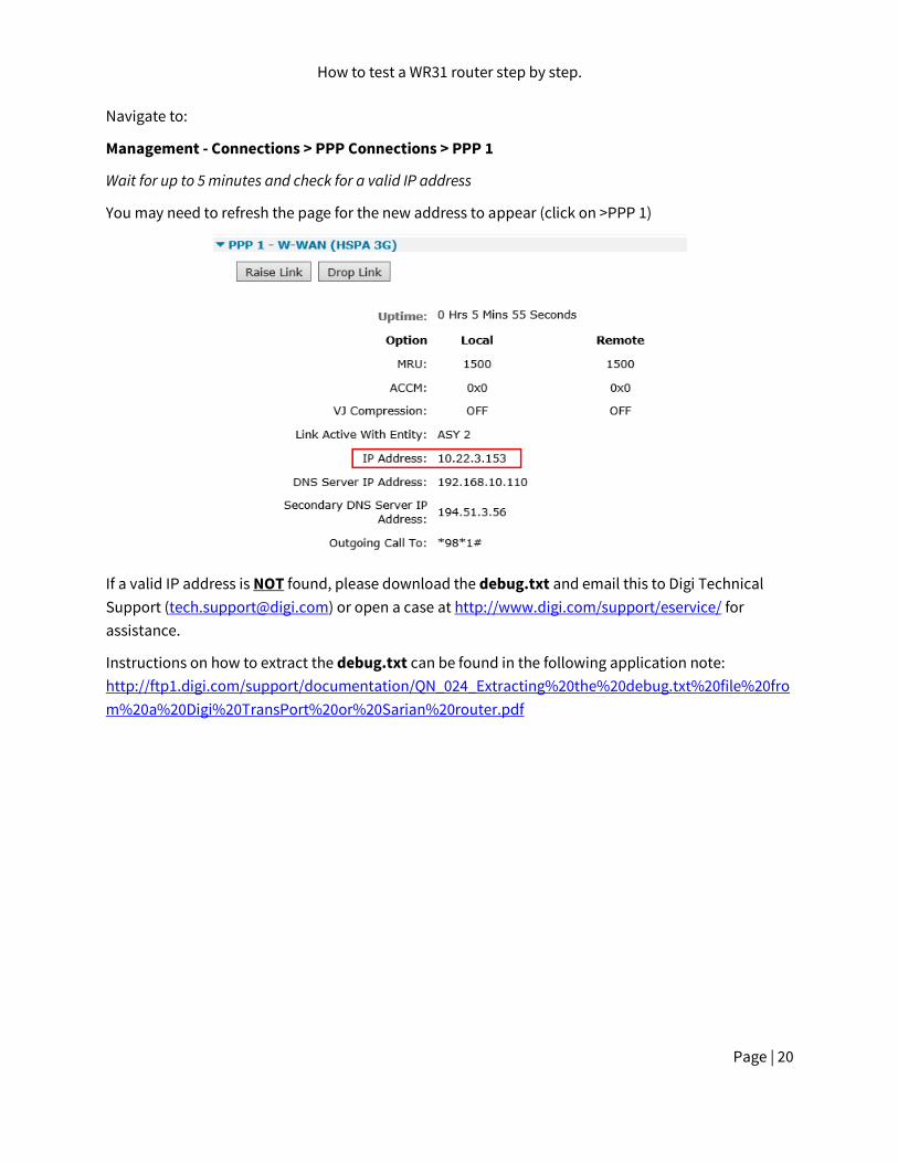
Navigate to:
Management - Connections > PPP Connections > PPP 1
Wait for up to 5 minutes and check for a valid IP address
You may need to refresh the page for the new address to appear (click on >PPP 1)
If a valid IP address is NOT found, please download the debug.txt and email this to Digi Technical
Support ([email protected]) or open a case at http://www.digi.com/support/eservice/ for
assistance.
Instructions on how to extract the debug.txt can be found in the following application note:
http://ftp1.digi.com/support/documentation/QN_024_Extracting%20the%20debug.txt%20file%20fro
m%20a%20Digi%20TransPort%20or%20Sarian%20router.pdf

How to test a WR31 router step by step.
Page | 21
5.3 Test SIM 2
Navigate to:
Configuration - Network > Interfaces > Advanced > PPP 1 > Mobile
Change “W-WAN SIM: from “SIM 1” to “SIM 2”
Click Apply.
Next navigate to
Configuration - Network > Interfaces > Mobile
And select SIM 2
And under “Mobile Settings”
Enter the correct APN for the SIM card installed in slot 2
Click Apply

How to test a WR31 router step by step.
Page | 22
Now Navigate to:
Management - Connections > PPP Connections > PPP 1
Click “Drop Link” and refresh the page by clicking >PPP 1
You may need to wait up to 5 minutes
A valid IP address for SIM 2 should be seen – Notice it is different to the one assigned for SIM 1
If a valid IP address is NOT found, please download the debug.txt and email this to Digi Technical
Support ([email protected]) or open a case at http://www.digi.com/support/eservice/ for
assistance.
Instructions on how to extract the debug.txt can be found in the following application note:
http://ftp1.digi.com/support/documentation/QN_024_Extracting%20the%20debug.txt%20file%20fro
m%20a%20Digi%20TransPort%20or%20Sarian%20router.pdf

How to test a WR31 router step by step.
Page | 23
6 CHECK W-WAN SIGNAL STRENGTH
Whilst the internet link is still connected from step 5, access the CLI (Command Line Interface)
Access to the CLI (Command Line Interface) – this can be achieved:
Through the serial port @115200 bps
Via a telnet or SSH connection
Via the “execute a command” page of the web user interface.
And issue the following command:
modemstat ?
Check that the signal strength is roughly what you normally get (+/- 10dB) with the same antenna in
the test location.
If the signal strength is much worse than normal, make a note of the cell ID (lac:FFFE ci:19FF701 in
above example) and repeat the test on a known working WR31 that contains the same type of radio

How to test a WR31 router step by step.
Page | 24
module in the same location. Ensure the known working WR31 is connected using the same antenna
and connects to the same cell ID (lac:00DF ci:01B0BD51 in above example). If it does and the signal
strength is much better (+ 10dB) than the suspected bad router, request an RMA from Digi technical
support with code: “Cellular signal strength low”
7 CHECK USB PORTS
Insert a valid USB device into the USB slots on the front of the WR31. A valid USB device is a device
that you know works in a WR31 because you have tried it previously. Examples to try:
USB Flash drive
USB Serial adapter
USB Mouse
Access to the CLI (Command Line Interface) – this can be achieved:
Through the serial port @115200 bps
Via a telnet or SSH connection
Via the “execute a command” page of the web user interface.
And issue the following command:
busb show
2 devices should normally be present:
Device in “BUS 1, dev2, depth 1” (There is a USB stick inserted)
Device in “BUS 2, dev2, depth 1” (This is a Huawei radio module, do not be concerned if it is
missing, the module may be mid power cycle. The text of this will vary based upon the type of
module fitted. )
If the device in BUS 1, dev2, depth 1 is not present and this same devices shows up fine in a known
working WR31,please request an RMA with code: “External USB port test failed”

How to test a WR31 router step by step.
Page | 25
8 CHECK ETH PORTS 1 AND 2
Note that it is not necessary to test Eth port 0. This was testing during the flashing process.
Access the CLI. Issue the command
id
and check that the router is in “port isolate mode”:
Otherwise, please enter the following CLI command and reboot afterwards:
ethvlan
Configure eth port 1 with a valid and free IP address on the same subnet as your test PC, e.g.
eth 1 ipaddr 192.168.1.1
From your PC, first clear the ARP table, from the Windows command prompt with the command:
arp –d *
Then check that you can ping this IP address from Windows.
If it works ok with ETH 0, repeat the test accordingly with ETH 1.
If it is not possible to ping this addresses and if you repeat this test on a known good WR31 and
it works fine, please request an RMA with code “ETH X test failed” where X is the Eth port number that failed to respond.
Please don’t forget to change back the Ethernet port mode back to the required mode!
It does not get changed via Factory Default!
The standard is Hub mode, which you select by the CLI command:
ethhub

How to test a WR31 router step by step.
Page | 26
9 CHECK SERIAL PORTS
With the PC serial port still connected to “Serial 0” of the WR31, launch Flashwriter again, ensure that the correct PC comm. port number is selected and click on “Check Serial” from the
Advanced menu of FlashWriter.
When the following prompt is received:
As you are testing “Serial 0” just click OK.
You should see this:
If any error messages occur, please refer to the following table to identify the best course of action:

How to test a WR31 router step by step.
Page | 27
Error Message Recommendation
Problem sending AT\LS
Flashwriter is unable to establish contact with the router under test. Please check the cabling and try again. If the problem persists then repeat the process with a known working router. If the test is successful on a known working router and the problem is repeatable on the router under test, please request an RMA with reason: “Flashwriter serial I/O test fail.”
Problem with DCD on (DCD was OFF when supposed to be ON)
First carefully check you are entering the correct serial/asy port number. If you get this wrong you will get a false fail! Next to verify cabling, please repeat this procedure on a known working router. If the test is successful on a known working router but repeatedly fails on the router under test then please request an RMA with reason: “Flashwriter DCD test fail.”
Problem with DCD on (DCD was ON when supposed to be OFF)
First carefully check you are entering the correct serial/asy port number. If you get this wrong you will get a false fail! Next to verify cabling, please repeat this procedure on a known working router. If the test is successful on a known working router but repeatedly fails on the router under test then please request an RMA with reason: “Flashwriter DCD test fail.”
Problem with DTR (DTR is off and should be ON)
To verify cabling, please repeat this procedure on a known working router. If the test is successful on a known working router but repeatedly fails on the router under test then please request an RMA with reason: “Flashwriter DTR test fail.”
Problem with DTR (DTR is ON and should be OFF) on
To verify cabling, please repeat this procedure on a known working router. If the test is successful on a known working router but repeatedly fails on the router under test then please request an RMA with reason: “Flashwriter DTR test fail.”
Problem with CTS (CTS is ON and should be OFF) on
To verify cabling, please repeat this procedure on a known working router. If the test is successful on a known working router but repeatedly fails on the router under test then please request an RMA with reason: “Flashwriter CTS test fail.”
Problem with CTS (CTS is OFF and should be ON) on
To verify cabling, please repeat this procedure on a known working router. If the test is successful on a known working router but repeatedly fails on the router under test then please request an RMA with reason: “Flashwriter CTS test fail.”