test and evaluation of meshdynamics 802.11 multi-radio ... · nsn 7540-01-280-5500 standard form...
TRANSCRIPT

Calhoun: The NPS Institutional Archive
Theses and Dissertations Thesis Collection
2006-06
Test and evaluation of meshdynamics 802.11
multi-radio mesh modules in support of coalition
riverine operations
Russo, Joseph Anthony.
Description based on title screen as viewed on July 18, 2011
http://hdl.handle.net/10945/2796

NAVAL
POSTGRADUATE SCHOOL
MONTEREY, CALIFORNIA
THESIS
Approved for public release; distribution is unlimited
TEST AND EVALUATION OF MESHDYNAMICS 802.11 MULTI-RADIO MESH MODULES IN SUPPORT OF
COALITION RIVERINE OPERATIONS by
Joseph Anthony Russo
June 2006
Thesis Advisor: James Ehlert Second Reader: R. Mitchell Brown, III Third Reader: Edward Fisher

THIS PAGE INTENTIONALLY LEFT BLANK

i
REPORT DOCUMENTATION PAGE Form Approved OMB No. 0704-0188
Public reporting burden for this collection of information is estimated to average 1 hour per response, including the time for reviewing instruction, searching existing data sources, gathering and maintaining the data needed, and completing and reviewing the collection of information. Send comments regarding this burden estimate or any other aspect of this collection of information, including suggestions for reducing this burden, to Washington headquarters Services, Directorate for Information Operations and Reports, 1215 Jefferson Davis Highway, Suite 1204, Arlington, VA 22202-4302, and to the Office of Management and Budget, Paperwork Reduction Project (0704-0188) Washington DC 20503. 1. AGENCY USE ONLY (Leave blank)
2. REPORT DATE June 2006
3. REPORT TYPE AND DATES COVERED Master’s Thesis
4. TITLE AND SUBTITLE Test and Evaluation of MeshDynamics 802.11 Multi-Radio Mesh Modules in Support of Coalition Riverine Operations 6. AUTHOR(S) Joseph Anthony Russo
5. FUNDING NUMBERS
7. PERFORMING ORGANIZATION NAME(S) AND ADDRESS(ES) Naval Postgraduate School Monterey, CA 93943-5000
8. PERFORMING ORGANIZATION REPORT NUMBER
9. SPONSORING /MONITORING AGENCY NAME(S) AND ADDRESS(ES) N/A
10. SPONSORING/MONITORING AGENCY REPORT NUMBER
11. SUPPLEMENTARY NOTES The views expressed in this thesis are those of the author and do not reflect the official policy or position of the Department of Defense or the U.S. Government. 12a. DISTRIBUTION / AVAILABILITY STATEMENT Approved for public release; distribution is unlimited
12b. DISTRIBUTION CODE
13. ABSTRACT (maximum 200 words) The Coalition Operating Area Surveillance and Targeting System (COASTS) program is a joint
project between the Naval Postgraduate School and the Royal Thai Armed Forces (RTARF). The program focuses its research on command, control, communications, computers, intelligence, surveillance and reconnaissance (C4ISR) uses for commercial-off-the-shelf (COTS), state-of-the-art, rapidly scaleable airborne and ground communications equipment, including various wireless network technologies. This research is being conducted in partnership with the RTAF to develop a network and associated devices and applications that potentially may help suppress drug trafficking in the northern Thailand border regions.
Commensurately, the U.S. Navy is taking the Global War on Terror (GWOT) lead in coalition Maritime Security Operations and riverine warfare operations. With formation of the new Naval Expeditionary Combat Command (NECC), and its new Riverine Warfare Group, the Navy’s role takes effect starting in January 2007, and could benefit from this research.
This thesis focuses on testing and evaluating the overall performance of the MeshDynamics Multiple-Radio Mesh Modules, operating in the 802.11 wireless frequency spectrum. These modules are key building blocks of meshed networks that provide coverage over an area where riverine and coastal operations are being conducted. The network provides an information source and communications backbone for maritime, ground, and air assets.
15. NUMBER OF PAGES
226
14. SUBJECT TERMS C4ISR, Maritime Security Operations, IEEE 802.11 Technology, Wi-Fi, Riverine Warfare, Wireless Meshed Networks
16. PRICE CODE
17. SECURITY CLASSIFICATION OF REPORT
Unclassified
18. SECURITY CLASSIFICATION OF THIS PAGE
Unclassified
19. SECURITY CLASSIFICATION OF ABSTRACT
Unclassified
20. LIMITATION OF ABSTRACT
UL NSN 7540-01-280-5500 Standard Form 298 (Rev. 2-89) Prescribed by ANSI Std. 239-18

ii
THIS PAGE INTENTIONALLY LEFT BLANK
iii
Approved for public release; distribution is unlimited
TEST AND EVALUATION OF MESHDYNAMICS 802.11 MULTI-RADIO MESH MODULES IN SUPPORT OF COALITION RIVERINE OPERATIONS
Joseph Anthony Russo Ensign, United States Navy
B.S., United States Naval Academy, 2005
Submitted in partial fulfillment of the requirements for the degree of
MASTER OF SCIENCE IN SYSTEMS TECHNOLOGY (Command, Control and Communications (C3))
from the
NAVAL POSTGRADUATE SCHOOL June 2006
Author: Joseph Anthony Russo Approved by: James Ehlert
Thesis Advisor
R. Mitchell Brown, III Second Reader Edward L. Fisher Third Reader Dan C. Boger, PhD Chairman, Department of Information Sciences

iv
THIS PAGE INTENTIONALLY LEFT BLANK

v
ABSTRACT
The Coalition Operating Area Surveillance and
Targeting System (COASTS) program is a joint project
between the Naval Postgraduate School and the Royal Thai
Armed Forces (RTARF). The program focuses its research on
command, control, communications, computers, intelligence,
surveillance and reconnaissance (C4ISR) uses for
commercial-off-the-shelf (COTS), state-of-the-art, rapidly
scaleable airborne and ground communications equipment,
including various wireless network technologies. This
research is being conducted in partnership with the RTARF
to develop a network and associated devices and
applications that potentially may help suppress drug
trafficking in the northern Thailand border regions.
Commensurately, the U.S. Navy is taking the Global War
on Terror (GWOT) lead in coalition Maritime Security
Operations and riverine warfare operations. With formation
of the new Naval Expeditionary Combat Command (NECC), and
its new Riverine Warfare Group, the Navy’s role takes
effect starting in January 2007, and could benefit from
this research.
This thesis focuses on testing and evaluating the
overall performance of the MeshDynamics Multiple-Radio Mesh
Modules, operating in the 802.11 wireless frequency
spectrum. These modules are key building blocks of meshed
networks that provide coverage over an area where riverine
and coastal operations are being conducted. The network
provides an information source and communications backbone
for maritime, ground, and air assets.

vi
THIS PAGE INTENTIONALLY LEFT BLANK

vii
TABLE OF CONTENTS
I. INTRODUCTION ............................................1 A. TRANSFORMATION OF MODERN DAY FORCES ................1 B. MARITIME DOMAIN AWARENESS ..........................2 C. RIVERINE WARFARE ...................................3 D. COASTS .............................................4
1. Situation .....................................4 2. Background ....................................5 3. COASTS 2005 RECAP .............................6 4. COASTS 2006 ...................................9
E. THESIS SCOPE ......................................12 II. U.S. NAVY RIVERINE WARFARE EVOLUTION AND DOCTRINE ......15
A. HISTORY OF U.S. NAVY RIVERINE WARFARE .............15 B. MODERN RIVERINE DOCTRINE ..........................19 C. NAVAL EXPEDITIONARY COMBAT COMMAND (NECC) .........21 D. APPLICATION OF COASTS 2006 TO U.S. NAVY RIVERINE
FORCES ............................................24 III. TECHNOLOGY DISCUSSION ..................................27
A. OUTLINE ...........................................27 B. WIRELESS MESHED NETWORKS (WMN) ....................27 C. MESHDYNAMICS 802.11 MULTIPLE-RADIO MESH MODULES ...30 D. ANTENNAS AND RADIOS ...............................37 E. AP MESHVIEWER .....................................42 F. IXCHARIOT .........................................44
IV. PREPARATION AND NETWORK DEPLOYMENT METHODOLOGY .........47 A. OVERVIEW ..........................................47 B. METHODOLOGY .......................................51 C. GROUND NODE DEPLOYMENT ............................53 D. AERIAL NODE DEPLOYMENT ............................55
1. Balloon ......................................56 2. Platform .....................................57 3. Payload ......................................58
E. POSSIBLE FUTURE RIVERINE OPERATIONS TOPOLOGY ......59 V. FIELD TESTING ITERATIONS ...............................63
A. POINT SUR .........................................63 1. Terrain ......................................63 2. Weather ......................................65 3. Objectives ...................................66 4. Topology .....................................67 5. Field Tests ..................................68 6. Results ......................................70
B. FORT ORD ..........................................72

viii
1. Terrain ......................................73 2. Weather ......................................74 3. Objectives ...................................74 4. Topology .....................................75 5. Field Tests ..................................75 6. Results ......................................77
C. FORT HUNTER LIGGETT ...............................79 1. Terrain ......................................79 2. Weather ......................................80 3. Objectives ...................................81 4. Topology .....................................82 5. Field Tests ..................................83 6. Results ......................................84
D. MAE NGAT DAM ......................................88 1. Terrain ......................................88 2. Weather ......................................88 3. Objectives ...................................89 4. Topology .....................................90 5. Field Tests ..................................96 6. Results ......................................98
VI. CONCLUSION ............................................101 A. OVERVIEW .........................................101 B. LESSONS LEARNED ..................................102 C. FUTURE RESEARCH ..................................104
APPENDIX A. COASTS 2005 CONCEPT OF OPERATIONS .............107 APPENDIX B. TETHERED BALLOON SET-UP ........................191 LIST OF REFERENCES .........................................199 INITIAL DISTRIBUTION LIST ..................................203

ix
LIST OF FIGURES
Figure 1. Different Models of Rajant BreadCrumbs®..........8 Figure 2. COASTS 2005 Network Topology.....................9 Figure 3. Map of Thailand (From:
www.greenwaythailand.org/fotos/map-thailand.jpg accessed June 8, 2006)..........................10
Figure 4. Areas of Operations in Maritime Security and Riverine Environments (From: Benbow et al., 2006, 46).......................................19
Figure 5. Organizational Breakdown of the NECC (From: Benbow et al., 2006, 8).........................22
Figure 6. MeshDynamics 802.11 Multiple-Radio Mesh Modules (From: www.meshdynamics.com\MDProductNRadio.html accessed June 8, 2006)..........................31
Figure 7. Port Numbers on Mesh Modules (From: http://www.meshdynamics.com/MDProductNRadio.html accessed June 8, 2006)........................33
Figure 8. Inside View of a 3-radio MeshDynamics Mesh Module..........................................34
Figure 9. Ubiquiti SuperRange2 Radio (left) and SuperRange2 Specifications (right) (From: http://www.comnet.com.au/Ubiquiti/SR2.htm accessed June 8, 2006)..........................38
Figure 10. Ubiquiti SuperRange5 Radio (left) and SuperRange5 Specifications (right) (From: http://www.comnet.com.au/Ubiquiti/SR5.htm accessed June 8, 2006)..........................38
Figure 11. SuperPass 8dbi Omni-directional Antenna(left) and 8dbi Antenna Beamwidths (From: http://www.superpass.com/SPDJ6O.html accessed June 8, 2006 )..................................39
Figure 12. WiFi-Plus 5dbi Antenna (From: http://www.wifi-plus.com/images/WFP0200507tearsheet.doc accessed June 8, 2006)..........................40
Figure 13. 5dbi Antenna Beamwidths (From: http://www.wifi-plus.com/images/WFP0200507tearsheet.doc accessed June 8, 2006)..........................40
Figure 14. SuperPass 9dbi Antenna (From: http://www.superpass.com/SPDG8O.html accessed June 8, 2006)...................................41
Figure 15. Hyperlink 12dbi Omni-directional Antenna (From: http://www.hyperlinktech.com/web/hg5812u_pro.php accessed June 8, 2006)........................41
x
Figure 16. WIFI-PLUS 13dbi Multi-Polar Antenna (From: http://www.wifi-plus.com/images/SpecsSingleSector2.pdf accessed June 8, 2006)...................................42
Figure 17. Screen Shot of AP Meshviewer (From: http://www.meshdynamics.com/WNetworkMgr.html accessed June 8, 2006)..........................43
Figure 18. AP Meshviewer Map and Topology Views (From: http://www.meshdynamics.com/WNetworkMgr.html accessed June 8, 2006)..........................44
Figure 19. Figure 19: Visual Description of How IxChariot Runs Tests (From: http://www.ixiacom.com/products/display?skey=ixchariot accessed June 8, 2006)..................45
Figure 20. COASTS 2006 Planned Topology....................47 Figure 21. COASTS 2006 Global Topology.....................49 Figure 22. Ground Node Deployment with Tri-Pod.............54 Figure 23. Ground Node Deployment on Light Post............55 Figure 24. COASTS 2006 Balloon.............................57 Figure 25. Platform with Helium and Winch..................58 Figure 26. Fully Assembled Payload (From: Lounsbury 2005)..59 Figure 27. Mae Ngat Dam and River with Current and Future
Network Coverage Areas..........................60 Figure 28. Point Sur Area of Operations Terrain Contour
(From: Google Earth 2006).......................64 Figure 29. Overhead View of Point Sur Area of Operations
(From: http://local.live.com/ accessed June 8, 2006)...........................................64
Figure 30. Point Sur Navy Facility (left) and Surrounding Terrain (right).................................65
Figure 31. Aerial Node Deployed at Pt. Sur.................67 Figure 32. Sloped Road Used for 802.11 Ground Node Testing
at Point Sur, CA................................69 Figure 33. Fort Ord Area of Operations (From:
http://local.live.com/ accessed June 8, 2006)...73 Figure 34. Fort Ord Range and Throughput Testing Track
(Blue Line)(From: http://local.live.com/ accessed June 8, 2006)..........................76
Figure 35. Ground Test Set-up at Fort Ord..................77 Figure 36. Fort Hunter Ligget Area of Operations (From:
Google Earth 2006)..............................79 Figure 37. Screen Shot of Surveillance Video Taken by AXIS
213 PZT Camera..................................86 Figure 38. MeshDynamics MeshViewer Screen Shot of Fort
Hunter Liggett 802.11 Network...................87

xi
Figure 39. Aerial View of Mae Ngat Dam (From: Google Earth 2006)...........................................88
Figure 40. Intended Mae Ngat Dam 802.11 Topology...........94 Figure 41. Aerial Payload Used at Mae Ngat Dam in March
2006............................................95 Figure 42. Installation of Ground Nodes on light poles at
Mae Ngat Dam....................................97 Figure 43. Screen Shot of Mae Ngat Dam 802.11 Network on
MeshViewer.....................................100

xii
THIS PAGE INTENTIONALLY LEFT BLANK

xiii
LIST OF TABLES
Table 1. MeshDynamics 802.11 Mutliple-Radio Mesh Module Specifications (From: http://www.meshdynamics.com/MDProductNRadio.html accessed June 8, 2006)........................32
Table 2. COASTS 2006 MeshDynamics Mesh Module Configurations (From: Lounsbury 2006)...........36
Table 3. MeshDynamics Mesh Module Model Number Breakdown (From: Lounsbury 2006)..........................36
Table 4. SuperPass 8dbi Omni-directional Antenna Specifications (From: http://www.superpass.com/SPDJ6O.html accessed June 8, 2006)...................................39
Table 5. Weather Conditions at Point Sur, CA from 03DEC – 09DEC.........................................66
Table 6. 802.11 Field Tests Performed at Point Sur.......70 Table 7. Weather Conditions at Fort Ord, CA from 13JAN –
15JAN...........................................74 Table 8. 802.11 Field Tests Performed at Fort Ord in
January 2006....................................76 Table 9. Weather Conditions at Fort Hunter Liggett on
11FEB2006 (From: http://www.wrh.noaa.gov/mesonet/getobext.php?wfo=mtr&sid=FHLC1&num=48 accessed June 8, 2006)...81
Table 10. 802.11 Field Tests Performed at Fort Hunter Liggett.........................................84
Table 11. Weather Conditions at Mae Ngat Dam..............89 Table 12. Mae Ngat Dam Ground Node Configurations for
22MAR2006.......................................91 Table 13. Mae Ngat Dam Ground Node Configurations for
23MAR2006.......................................92 Table 14. Mae Ngat Dam Ground Node Configurations for
28MAR2006.......................................93 Table 15. Mae Ngat Dam Aerial Node Configurations.........95 Table 16. 802.11 Field Tests Performed at the Mae Ngat
Dam.............................................98

xiv
THIS PAGE INTENTIONALLY LEFT BLANK
xv
LIST OF ACRONYMS AND ABBREVIATIONS
AP Access Point
C2 Command and Control
COASTS Coalition Operating Area Surveillance and Targeting System
CONOPS Concept of Operations
COTS Commercial off the Shelf
FHL Fort Hunter Liggett
GHz Giga Hertz
GPS Global Positioning System
GWOT Global War on Terror
HFN Hastily Formed Networks
IEEE Institute of Electrical and Electronic Engineers
LOS Line of Sight
Mbps Mega-bits per second
MOE Measures of Effectiveness
MOP Measures of Performance
NCW Network Centric Warfare
NECC Naval Expeditionary Combat Command
NPS Naval Postgraduate School
PZT Pan Zoom Tilt
RF Radio Frequency
RTAF Royal Thai Air Force
RTARF Royal Thai Armed Forces
SATCOM Satellite Communications
SSA Shared Situational Awareness
TOC Tactical Operations Center
UAV Unmanned Aerial Vehicle
WI-FI Wireless Fidelity

xvi
WLAN Wireless Local Area Network
VLAN Virtual Land Area Network

xvii
ACKNOWLEDGMENTS
I would most importantly like to thank Prof. Jim
Ehlert, who is the reason I even had an opportunity to work
on this project. His constant guidance and motivation
throughout the year was a tremendous help. As one of his
many advisees, I appreciate the time and effort that Prof.
Ehlert put into helping me throughout the year. His
guidance not only in school, but also out of school (Chang,
Baht Chains, SPICY’S) has made my entire NPS experience
worthwhile. The experiences that I had with the COASTS
team would not be possible without his help, or his
willingness to occasionally just shake his head and laugh
at the stories he has heard (FHL, Sharky’s, Mae Ngat AAR
Meeting).
Secondly, I want to thank Prof. Mitch Brown for taking
a lost young Ensign like myself as one of his advisees. In
the last few months of my research, Prof. Brown was a huge
help in guiding me through the thesis process and making it
go as smoothly as possible. His Navy war stories and
desire to apply my thesis to future Navy operations
motivated me through the final weeks of writing.
Thirdly, I would like to thank Prof. Ed Fisher for
voluntarily taking on the role as a third reader for my
thesis. Many of his “Chang worthy” pointers were a great
help throughout the writing process.

xviii
And last but not least, I want to thank Swampy, Ho,
Jon, Cnut, Red, Twister, Rob, and Scott. You guys have
become some of my best friends and made this year’s project
a fun and worthwhile experience. A special thanks to the
A-team.

1
I. INTRODUCTION
A. TRANSFORMATION OF MODERN DAY FORCES
The constant advancement of technology in today’s
world has transformed the military forces in the United
States, as well as in many other nations around the world.
Advancements in information technology, in particular, have
generated interest in a more futuristic style of combat
known as “Network Centric Warfare” (Alberts et al., 1999).
NCW has been defined as “an information-superiority enabled
concept of operations that generates increased combat power
by networking sensors, decision makers, and shooters to
achieve shared awareness, increased speed of command,
higher tempo of operations, greater lethality, increased
survivability, and a degree of self-synchronization.”
(Alberts et al. 1999)
In May 2000, the United States’ Joint Chiefs of Staff
released “Joint Vision 2020” (JV2020). This document
emphasized the goal of having a joint force capable of
full-spectrum dominance, persuasive in peace, decisive in
war, and preeminent in any form of conflict (Dept. of
Defense 2000, 1). The concepts of dominant maneuver,
precision engagement, focused logistics, and full
dimensional protection are the foundation of JV2020.
Furthermore, JV2020 “focuses on three factors as central to
success in these four operational concepts and the
resulting capability of full-spectrum dominance:
Interoperability, Innovation, and Decision Superiority
(Dept. of Defense 2000, 1).”

2
Information superiority is central to our constantly
evolving forces. The speed at which US military forces
gather and disseminate information directly affects mission
success across the full spectrum of operations. Since the
start of Operation ENDURING FREEDOM and Operation IRAQI
FREEDOM, U.S. and Coalition forces have applied modern-day
technologies to support the concept of Network Centric
Warfare espoused by JV2020. Quite successfully, NCW
capabilities have also been employed to support
peacekeeping and peace enforcement operations globally.
B. MARITIME DOMAIN AWARENESS
Since the events of September 11, 2001, much has been
done to revamp the United States’ National Defense
Strategy. In particular, protecting the maritime domain
has received much emphasis. The “maritime domain” is
defined as all areas relating to, adjacent to, or bordering
a sea, ocean, or other navigable waterway, including all
maritime-related activities, infrastructure, people, cargo,
and vessels and other conveyances (Dept. of Homeland
Security 2005, 1). On December 21, 2004, National Security
Presidential Directive #41 and Homeland Security
Presidential Directive #13 was released with Maritime
Security Policy as its subject matter. This directive
established U.S. policy, guidelines, and implementation
actions to enhance U.S. national security and homeland
security by protecting U.S. maritime interests. Maritime
security is an issue that concerns not only the U.S. but
the entire globe. According to the directive, “the United
States, in cooperation with our allies and friends around
the world and our State, local, and private sector
partners, will work to ensure that lawful private and
3
public activities in the Maritime Domain are protected
against attack and criminal and otherwise unlawful hostile
exploitation. These efforts are critical to global
economic stability, security and growth (NSPD-41/HSPD-13
2004, 2).” Unprecedented advances in information technology
and telecommunications have increased the range and
effectiveness of terrorist and criminal acts, as well as
our ability to prevent and to defend against them.
According to this Maritime Security Policy, some other
important measures that the U.S. must undertake are
• Expediting recovery and response from attacks within the Maritime Domain
• Maximizing awareness of security issues in the Maritime Domain in order to support U.S. forces and to improve response to identified threats
• Enhancing international relationships and promoting the integration of international partners in order to improve the global maritime security framework
• Ensuring the implementation of responsibilities that maintain a secure Maritime Domain (NSPD-41/HSPD-13 2004, 3).
C. RIVERINE WARFARE
Dating back to the American Revolution, the U.S.
Navy’s history of riverine warfare operations is quite
substantial. However, the last major campaign involving
Navy riverine forces was the Vietnam War. This campaign is
also very significant because there are several lessons
learned that can be applied to the development of today’s
riverine forces. The asymmetric war-fighting tactics of
the enemy forces along with the riverine and jungle
environments in the Vietnam War have several similarities
to the enemies that U.S. forces are encountering in

4
today’s Global War on Terror (GWOT). In order to combat
the terrorists in this ongoing war, the U.S. Navy is taking
steps to resurrect its riverine warfare roots. With the
formation of a new command called the Naval Expeditionary
Combat Command, containing within it a new Riverine Warfare
Group, the Navy hopes to begin playing a role in Maritime
Security Operations and riverine warfare operations in the
GWOT starting in 2007.
D. COASTS
1. Situation
Currently most of the drug smuggling activity
occurring in Thailand is concentrated in the northern
border areas, while most of the civil unrest is occurring
in the south. Both of these regions of the border are
quite rugged and require many resources to manage, making
these locations ideal for drug and terrorist or insurgent
operations. The development of a robust and rapidly
deployable network that is equipped with increased
bandwidth and modern surveillance technologies can greatly
aid the Thai military and law enforcement agencies to
accomplish their counterinsurgency and counter-drug
missions.
The importance of a coalition-oriented focus for
modern Maritime Domain Awareness and Protection operations
has become a major priority of U.S. combatant commanders.
In a recent naval message, all numbered fleet commanders
stated that their number one Command, Control, Computers,
Communications, Intelligence, Surveillance, and
Reconnaissance (C4ISR) requirement was improved coalition
communications (COASTS CONOPS 2006, 7). Current and future
operational capabilities are tightly tied to improved

5
interoperability with U.S. allies in the operational
theater. As reflected by the increasing number of requests
to the Naval Postgraduate School from foreign partners,
there is an immediate requirement for low-cost, state-of-
the-art, real-time threat warning and tactical
communication equipment that is also rapidly scaleable
based on operational and tactical considerations (COASTS
CONOPS 2006, 7). This issue has become especially apparent
in the face of the overwhelming mission requirements placed
on US forces conducting the Global War on Terror (GWOT).
The GWOT extends globally where nations are engaged in
direct action against numerous forces employing asymmetric
tactics. In Thailand, the separatist insurgency in the
southern provinces is connected to various transnational
terrorist organizations, to include both the Jemaah
Islamiyah (JI) and Al-Qaeda, which have struck against both
the U.S. and its allies (COASTS CONOPS 2006, 3).
2. Background
In its second year of existence, the Coalition
Operating Area Surveillance and Targeting System (COASTS)
is modeled after a highly successful ongoing NPS-driven
field experimentation program entitled the “NPS-U.S.
Special Operations Command Field Experimentation Program”
(NPSSOCFEP). NPSSOCFEP is executed by NPS, in cooperation
with U.S. Special Operations Command (USSOCOM) and several
contractors and has been active since FY2002. The
program’s inception supported USSOCOM requirements by
integrating emerging wireless local area network (WLAN)
technologies with surveillance and targeting
hardware/software systems to augment Special Operations
Forces (SOF) missions. (COASTS CONOPS 2006, 1)

6
The COASTS field experimentation program supports the
science and technology research requirements relating to
theater and national security, counter-drug and law
enforcement missions, and the GWOT for the following
organizations:
• U.S. Pacific Command (USPACOM)
• Joint Interagency Task Force West (JIATF-W)
• Joint U.S. Military Advisory Group Thailand (JUSMAGTHAI)
• U.S. Special Operations Command (USSOCOM)
• Naval Postgraduate School (NPS)
• Royal Thai Armed Forces (RTARF)
• Thai Department of Research & Development Office (DRDO) (COASTS CONOPS 2006, 2)
The COASTS program is a joint project between NPS and
the Royal Thai Armed Forces. The program focuses research
on commercial-off-the-shelf (COTS), state-of-the-art,
rapidly scaleable airborne and ground communications
equipment, including various wireless network technologies.
This research is being conducted in partnership with the
Royal Thai Armed Forces to develop a network and associated
devices and applications that potentially may help suppress
the drug trafficking in northern Thailand.
3. COASTS 2005 RECAP
In May 2005, the COASTS team conducted field
experiments in the Royal Thai Air Force Wing 2 (Lop Buri)
training area. The team successfully integrated Unmanned
Aerial Vehicles (UAVs), aerial balloons, portable and fixed
ground-based sensors, Global Positioning System (GPS) and
non-GPS enabled tracking systems, as well as other
technologies to provide shared situational awareness to

7
local and strategic users. The main focus of this
deployment was to integrate all of the sensor data at a
Royal Thai Army command and control vehicle, called a
Mobile Command Platform (MCP), and then to link it to the
Royal Thai Armed Forces headquarters located in Bangkok,
Thailand. However, due to real-world operational
commitments, the MCP asset was never fully integrated in
the field experiments (COASTS After Action Report 2005,
Enclosure 2).
Also, the wireless communication network deployed to
assist with tactical communications was never fully
realized. The IEEE 802.11b standard was used as the
backbone of this network and employed Rajant Technologies
hardware; specifically their meshed wireless access points
known as BreadCrumbs®. The BreadCrumbs® that were deployed
included the XL, SE, and ME models (Figure 1). These
devices were compliant with 802.11b and varied in size,
power, and range. The Rajant Breadcrumbs® proved to be an
unreliable solution for the hostile environment in which
they were used, as weather and distance severely diminished
their performance. The inability to cool these devices
caused them to overheat on a regular basis. As a result,
the intended placement of wireless access points in the
overall network topology had to be adjusted considerably.
The following recommendations were taken from the COASTS
2005 After Action Report:
• Change the color of the boxes (black is not the optimum choice) as this color absorbs heat and makes the BreadCrumbs® susceptible to failure under conditions of high temperature and humidity. These devices should consider some sort

8
of internal fan or environmental control when used in environments such as those experienced in Thailand.
• The situational awareness software that is used to manage the Breadcrumbs®, known as “BCAdmin”, uses about 2 Mbps of network traffic per operating client. The number of clients running should be limited to provide more bandwidth.
• The 802.11b operating space is limited and future product iterations should consider upgrading to the IEEE standard of 802.11g or 802.11n for better range and throughput.
• To better deploy the Rajant Breadcrumbs® to tactical hostile environments, employing an overlapping, redundant mesh is essential. Single Breadcrumbs® would work less reliably than two co-located Breadcrumbs.
• If Breadcrumbs are to be used as wireless access points for aerial balloon payloads, two separate Breadcrumbs® should be used in a given footprint.
Figure 1. Different Models of Rajant BreadCrumbs®

9
Another challenge that the network faced was a lack of
redundancy. In the environmentally severe conditions found
at Lop Buri, problems can occur with any and all electronic
devices, and it is important to ensure that as few points
of failure exist as possible. Due to fiscal constraints,
the team did not deploy with enough Breadcrumbs® to
construct an overlapping, redundant mesh. Figure 2 shows
the overall topology developed by the COASTS 2005 team.
Figure 2. COASTS 2005 Network Topology
4. COASTS 2006
COASTS 2006 expanded upon the original field
experiment conducted during last year’s deployment to Wing
2, Lop Buri, Thailand. This year’s network topology
advanced research relative to low-cost, commercially
available solutions while integrating each
technology/capability into a larger system of systems in
support of tactical action scenarios (COASTS CONOPS 2006,
3). The demonstration that took place in March 2006 was an

10
air-, ground-, and water-based scenario, occurring just
north of Chiang Mai, Thailand at the Mae Ngat Dam. Figure
3 is a map of Thailand and some of its bordering countries.
Figure 3. Map of Thailand (From: www.greenwaythailand.org/fotos/map-thailand.jpg
accessed June 8, 2006)
The scenario encompassed first-responder, law
enforcement, counter-terrorism, and counter-drug
objectives. The tactical information that was collected
from the scenario was fused, displayed, and distributed in
real-time to local (Chiang Mai), theater (Bangkok), and
global (Alameda and Monterey, CA) Command and Control (C2)

11
centers. COASTS 2006 will examine the feasibility of
rapidly deploying networks and explore sustainment
considerations with respect to a hostile climactic
environment (COASTS CONOPS 2006, 3).
This year’s team spent much time performing field
testing in the months prior to deploying to Thailand.
Testing sessions took place at the following locations and
times:
• Pt. Sur, CA in December 2005
• Fort Ord, CA in January 2006
• Fort Hunter Liggett, CA in January/February 2006
• Mae Ngat Dam (Thailand) in March 2006
• Mae Ngat Dam (Thailand) in May 2006.
Continuing with last year’s research theme, the COASTS
2006 team examined the feasibility of rapidly-deploying
networks, called “Fly-away Kits” (FLAK) and explored
sustainment considerations with respect to a hostile
climatic (temperature, humidity, wind, etc.) environment.
Network improvements included the testing and evaluating of
new 802.11g mesh WLAN equipment, the refinement of a
jointly-developed (NPS and Mercury Data Systems) 3-D
topographic shared situational awareness (SSA) application
called C3Trak, and integration of “satellite in a suitcase”
(portable satellite communication equipment) technology.
Some other improvements included the enhancement of
unattended ground and water-based sensors, new balloon and
UAV designs, portable biometric devices, portable explosive
residue detecting devices, and revised operational
procedures for deploying of the network (COASTS CONOPS
2006, 3-4).

12
E. THESIS SCOPE
This thesis primarily researches the effectiveness of
the MeshDynamics Multiple-Radio Mesh Modules in augmenting
the Command, Control, Communications, and Computers for
Intelligence, Surveillance, and Reconnaissance (C4ISR)
capability in support of coalition maritime and coastal
security operations.
Secondary research addresses network performance to
include an examination of the following issues and
questions:
• What is the effectiveness of the MeshDynamics Multiple-Radio Mesh Modules in providing an effective wireless meshed network and backbone in support of tactical coalition operations in a maritime and coastal environment, specifically?
• What effects do balloon payload altitudes have on network connectivity?
• What effects do the environmental conditions and regional landscape conditions have on network performance?
• What is the optimal antenna configuration for the network based on a variety of deployment topologies?
• What is the most effective radio-antenna combination (50 mW radio + 8 dbi antenna, 400 mW radio + 12 dbi antenna, etc.) in terms of network performance?
• How well does the network support live video feeds from multiple nodes?
The tertiary questions dealing with network topology
that this thesis explores are
• What is the optimal altitude for the balloon nodes?
• What is the optimal distance between the nodes?

13
• What is the optimal number of nodes that should be employed to set up the wireless mesh?
• How many ground nodes must be employed as part of the meshed network?
• What is the optimal network topology to support reliable (redundant) communications for critical networks?
• What is the optimal antenna configuration to support reliable (redundant) communications for critical networks?
Additionally, the context for use of this type of
technology is raised as a potential force multiplier for
the new U.S. Riverine forces, which are scheduled to deploy
in Iraq by January 2007. The U.S. Navy will then take over
responsibility from the U.S. Marine Corps in defense of the
vital Haditha Dam complex, located on the Euphrates River
in western Iraq. Establishing situational awareness by
employing a proven Coalition Operating Area Surveillance
and Targeting System (COASTS) could help ensure more
effective mission accomplishment.
In the end, the research conducted as part of this
thesis will pave the way for successful operational and
tactical deployment of wireless C2 networks in support of
future coalition counter-drug, -insurgency, and –terrorist
missions.

14
THIS PAGE INTENTIONALLY LEFT BLANK
15
II. U.S. NAVY RIVERINE WARFARE EVOLUTION AND DOCTRINE
The doctrine for US Riverine Warfare is still
evolving. Although riverine warfare is not a new concept
for the US Navy, it has been set aside somewhat since the
Vietnam War era. In May 2005, a Global War On Terror
(GWOT) Working Group was formed by the Chief of Naval
Operations (CNO) to support the Quadrennial Defense Review.
The group identified several gaps in the US Navy’s riverine
capabilities, expeditionary support, and the Navy’s ability
to engage countries in matters pertaining to internal
defense and security assistance (Benbow et al., 1). This
chapter examines what the US has attempted and accomplished
in filling these gaps and how history has played a role in
the process.
A. HISTORY OF U.S. NAVY RIVERINE WARFARE
Although the Navy has a long record of riverine
operations, its record has been more episodic than
continuous. The Navy has conducted numerous riverine
campaigns dating back to the American Revolution; however,
the end of each of these campaigns often resulted in the
disbanding of the riverine units and the removal of
riverine capabilities from the Navy’s inventory (Benbow et
al. 2006, 13).
Based on the riverine campaigns which the US Navy has
conducted, there is no one mission set or force construct
that has characterized them (Benbow et al. 2006, 11). The
Navy’s record of riverine operations encompasses a wide
variety of missions and tasks to include:

16
• River assault
• Lines of communication protection
• Security operations
• River crossings
• Operations other than war
• Theater security cooperation
• Homeland security
• Counter-drug operations (Benbow et al. 2006, 11).
Many of these missions have also varied in scale and
physical environment.
The following is a list of some of the major campaigns
in which the US Navy has made use of its riverine
warfighting capabilities:
• American Revolution
• Civil War
• Yangtze River Operations (China)
• Vietnam War.
One of the key tenets taken from the Civil War was the
importance of jointness among forces. According to Dr.
Craig L. Symonds, former US Naval Academy professor and
distinguished author,
The ability of an army-navy team to work together depended on the on-scene officers’ ”willingness to cooperate.” The battles for Fort Henry, Fort Donelson, and Island No. 10 were significant attempts at this nascent military jointness. It was jointness, ultimately, that won the river war, “and that is still the key today (Mills 2006, 3).
On top of being the last major campaign in which USN
riverine forces were used, Vietnam is also regarded as a
reference for the development of today’s modern riverine

17
doctrine. However, according to Dr. Edward J. Marolda,
senior historian at the Naval Historical Center:
Riverine warfare did not come naturally to the Navy after World War II,’ which had imbued America’s sea strategists with the concept of big, blue-water battles. It was JFK’s advocacy that was crucial in steering the Navy in a riverine direction in the early 1960s, despite initial pushback by those in the Navy who saw river ops as outside the primary-mission sphere (Mills 2006, 5).
The five major mission areas in which US riverine
forces acted on in the Vietnam War were
• River Assault
• River Patrol and Control
• River Minesweeping
• Special Operations Support
• Fire Support from Riverine Forces.
Along with the lessons learned from the above
missions, another major lesson was the importance of
jointness (again, as in the Civil War) and
interoperability. With over 22,500 personnel deployed in
support of the riverine forces in Vietnam, the two key
players in this role were aviation operations and logistics
support (Benbow et al. 2006, 17). Aviation units supported
the riverine forces with surveillance, fires, insertion,
extraction, medical evacuation, and other tasks. The two
main aviation support units during the Vietnam War were the
HAL-3 Seawolves attack helicopter squadron and the VAL-4
Black Ponies attack airplane squadron. In a discussion
with Professor Mitch Brown, a retired Navy Commander and
former Seawolf, he stressed the importance of air, water,
and land units all supporting each other in riverine

18
operations. Professor Brown recalled several instances in
which he was sent in to insert and extract Navy SEAL units
from hot spots in Vietnam. He also cited how reciprocally,
SEALs agreed to be sent in to extract pilots from a crash
site.
Logistics support entailed bases that were both ashore
and afloat. Support ships provided functions such as
• Command and control
• Berthing and Messing
• Medical Support
• Supply Support
• Maintenance and Repair Support
• Naval Gunfire Support (Benbow et al. 2006, 17).
The importance of the roles played by these support
teams indicated that riverine forces could not operate
alone. The riverine environment is one in which ground and
naval units, as well as air combat units, routinely operate
(Benbow et al. 2006, 20). This interoperability is most
important because of the versatility that riverine forces
must have. According to Captain Joseph Hock, commander of
River Squadron 51 in Vietnam from 1969 to 1970, “Riverine
warfare is not control of just the rivers and canals, it is
control of the whole area, and that takes more than just
boats. You have to become part of the culture. You have
to integrate (Mills 2006, 5).”
Now with the GWOT, the lessons learned from past
riverine operations are being used to form a modern
doctrine that supports today’s missions. However, the
concepts of jointness and interoperability still remain the
tenets of modern riverine doctrine.

19
B. MODERN RIVERINE DOCTRINE
The need to establish a new and improved riverine
force has become a high priority item for US military
leadership. The only resource the Navy has to start with
is its base of doctrine and lessons learned from its long
history of similar campaigns. However, platforms in the US
Navy’s inventory, such as helicopters and patrol craft
(PC), will be crucial in the support missions required to
initiate riverine operations. Currently, the US Marine
Corps and Army have the lead role in worldwide riverine
operations, so it is important for the Navy to cooperate in
a joint environment until it can support most of the
elements of a riverine force on its own. Figure 4 shows
all of the different areas that overlap in operations for
maritime security and riverine operations. This figure
emphasizes the fact that riverine operations are inherently
joint. Land, maritime, and air assets are all key elements
that must be working together along with logistics support.
Figure 4. Areas of Operations in Maritime Security and
Riverine Environments (From: Benbow et al., 2006, 46)

20
On July 6, 2005, former CNO, Admiral Vernon Clark
called for an expansion of the Navy’s capabilities in order
to be victorious in the GWOT. One of the actions he called
for was the establishment of a riverine force (Benbow et
al. 2006, 5). This idea was emphasized again by Admiral
Mullen, the current CNO. Admiral Mullen stated,
We need a fleet that can operate at the other end of the spectrum. We need a green-water capability and a brown-water capability. I want a balanced force in every sense of the word. I believe our Navy is missing a great opportunity to influence events by not having a riverine force. We’re going to have one (Benbow et al., 2006, 5).
Since the end of the Cold War, not much attention has
been placed on developing the riverine capabilities of our
Navy. When people think of the US Navy, they think blue-
water Navy, a force with large ships, including aircraft
carriers, cruisers, destroyers, and nuclear submarines.
However, the threat that our nation currently faces is one
that is characterized by terrorists and insurgents
operating in riverine and coastal environments in third-
world countries. Also important to understand is that in
many of these countries, the waterways are central to their
societies. Rivers function as means of transportation, as
well as communication and commerce.
Since the start of Operation Iraqi Freedom (OIF), the
majority of riverine operations in Iraq have been conducted
by the US Marine Corps, US Army, and US Special Operations
Command. However, the Marine Corps is now in the process

21
of relieving itself from this role. With the Marine Corps
stepping down, the proper time for the Navy to assume this
role is now.
C. NAVAL EXPEDITIONARY COMBAT COMMAND (NECC)
The Navy has begun taking steps to develop our
nation’s riverine forces. Essentially starting from
scratch as a new command, the Naval Expeditionary Combat
Command (NECC), as part of the Navy’s U.S. Fleet Forces
Command, was formed in October 2005 with Rear Admiral
Donald K. Bullard as its commander. Within the overall
NECC, the Navy’s Riverine Force will primarily focus on
conducting Maritime Security Operations in the GWOT, a
mission that has thus far been performed by the US Marine
Corps. The main missions of this new Navy riverine force
will include:
• Riverine area control/denial
• Interdiction of riverine lines of communication
• Insertion / extraction of conventional ground forces
• Fire support
• Theater security cooperation (Riverine Force CONOPS 2006).
Under this command, the intent is to establish a
Riverine Group with three active component Riverine
Squadrons and three Reserve Component augmentation units
(Riverine Force CONOP, March 2006). Along with the
riverine combat element, the 40,000-strong NECC will be
composed of other combat elements to include:
• Naval Coastal Warfare (NCW) – formerly part of Maritime Force Protection Command (MARFPCOM)
• Explosive Ordinance Disposal (EOD) – formerly part of MARFPCOM

22
• Mobile Diving and Salvage
• Naval Expeditionary Logistics Support
• Naval Construction
• Naval Security
• Other specialized naval forces (Benbow et al. 2006, 7).
Figure 5 below breaks down the NECC into its
individual combat and support elements.
Figure 5. Organizational Breakdown of the NECC (From:
Benbow et al., 2006, 8)
As depicted above, the Riverine component of the NECC,
called Riverine Warfare Group One (NRG-1), is to be
composed of three squadrons with the first squadron to
become operational in January 2007. The remaining two
squadrons will activate in 2008 and 2009.
23
The riverine squadrons will comprise sixteen riverine
craft in four separate groups, each composed of four
riverine craft (three active and one reserve). Each craft
will have two separate five-man crews to enable port and
starboard rotation during surge operations (Benbow et al.
2006, 8). Presently, the first squadron will be mission-
focused on Maritime Security Operations in support of
OPERATION IRAQI FREEDOM (OIF) starting in January 2007.
When these riverine squadrons become operational, one must
remember that riverine operations require both aviation and
logistics support in order to be effective. The squadrons
will rely on aviation units for tasking that may include:
• Air interdiction
• Close air support (CAS) – integrated, attached, assigned, or on call
• Surveillance, reconnaissance, and electronic support
• Inter and intra-theater lift including both tactical and logistical (Riverine Force CONOPS 2006).
Not much has been documented in regards to the
aviation units that will be supporting these newly formed
riverine squadrons, but it must be a high-priority item to
allow riverine units to successfully perform their
missions. Dedicated air assets need to be identified and
configured with appropriate C4ISR systems that are
interoperable with ground-based systems.
Another crucial factor to consider in the formation of
the Navy’s new riverine force is the development of a
command structure that allows for the integration of each
element with command, control, communications, computers,
and intelligence (C4I) resources. Development of the NECC

24
and its respective riverine combat units is where the
COASTS 2006 team becomes significant.
D. APPLICATION OF COASTS 2006 TO U.S. NAVY RIVERINE FORCES
In order to fuse the research done by the COASTS 2006
team and the development of the U.S. Navy’s new riverine
forces, recapping the missions of both organizations is
important. COASTS 2006 has conducted research of
relatively low-cost, commercially available solutions while
integrating each technology/capability into a larger system
of systems in support of tactical action scenarios. This
year’s COASTS scenario took place at the Mae Ngat Dam,
located just north of Chiang Mai, Thailand. The air-,
ground-, and water-based scenario encompassed first-
responder, law enforcement, counter-terrorism, and counter-
drug objectives (COASTS CONOPS 2006, 3). The network that
the COASTS team developed served as the central C4ISR asset
that integrated all of the air-, ground-, and water-based
units, allowing them to share information with one another
in a real-time environment.
The Navy’s Riverine Force will serve the primary
purpose of conducting Maritime Security Operations in the
GWOT. This multifaceted mission will require coordination
with joint forces, as well as coalition partners. The
presence of a common operating environment that seamlessly
integrates all of the units involved in any type of
maritime security or riverine operation is essential to
ensure that all of the combat and support elements can take
advantage of one another’s strengths.
The solution that COASTS 2006 provided was used
specifically in conjunction with the Royal Thai Armed

25
Forces to provide full situational awareness to units
performing counter-drug operations in a riverine
environment. However, the C4ISR architecture developed by
COASTS 2006 is not limited to use with this specific type
of operation. With the GWOT extending globally where
nations, especially the U.S., are engaged in direct actions
against numerous forces operating in environments other
than the open ocean, this type of C4ISR architecture
established by the COASTS 2006 team will have great
utility. Three of the basic elements of the COASTS 2006
architecture were
• C4ISR suite
• A threat warning system
• Intelligence collection system (COASTS CONOPS 2006, 17)
All three of these elements were part of a system of
systems that could be used to support a wide variety of
maritime security and riverine warfare operations.
With January 2007 approaching quickly, the NECC must
ensure that solid C4I architecture is implemented before
activating any of the riverine squadrons. Depending on the
development that has been achieved to this point, the C4I
architecture and common operating environment suite that
the COASTS 2006 team developed may serve as an excellent
starting point for the NECC and U.S. Navy Riverine Warfare
Group One.

26
THIS PAGE INTENTIONALLY LEFT BLANK

27
III. TECHNOLOGY DISCUSSION
A. OUTLINE
This chapter specifically surveys the architecture
considerations and technologies used in the development of
the COASTS 2006 network. The first section discusses the
concept of wireless meshed networks and their associated
advantages and disadvantages. The following sections
contain information about specific pieces of equipment and
software that are used within the COASTS network topology.
Section C details the design and the use of the
MeshDynamics 802.11 Multiple-Radio Mesh Modules that serve
as the key building blocks of the COASTS network. Section
D focuses on the different antennas and radios that are
used in conjunction with the MeshDynamics Modules.
Throughout the months of testing, various antenna and radio
configurations were tested to determine which possible
combinations would provide the most reliable wireless
meshed network. Sections E and F discuss two different
types of software that were used to analyze the performance
of the MeshDynamics modules during both the individual
testing and network setup.
B. WIRELESS MESHED NETWORKS (WMN)
Advances in wireless technology still require more
research and development, and subsequent testing and
evaluation, before reaching their full operational
potential. One of the key Internet access technologies
that is drawing significant attention these days is
wireless meshed networks (WMN). WMNs are an inexpensive
way to provide last-mile broadband Internet access (Jun and
Sichitiu 2002).

28
Wireless meshed networks have several advantages over
the other broadband technologies, including cable, DSL, and
satellite Internet access. The initial upfront costs for
setting up a WMN are low. Because these networks can be
easily up-scaled, the initial setup only requires a few
nodes to be installed. After that, the technology allows
for the installment of additional nodes as required. As
the number of nodes within the WMN increases, the
reliability and overall geographic coverage of the network
also increases. Another advantage of the WMN is that they
are dynamically self-organizing and self-configuring, with
the nodes in the network automatically establishing and
maintaining routes among themselves (Jun and Sichitiu
2002). These nodes, or network clients, also have the
option to be stationary or mobile, creating a more flexible
network.
In the WMN, each node acts not only as a host, but
also as a wireless router (Alicherry et al., 2005). This
dual role of node and router serves as the key element of a
wireless meshed network. As with any meshed network,
whether wired or wireless, there is one master element, or
node, that serves as the gateway between the Internet and
the entire meshed network. Subsequently, each additional
node that is added to the network becomes part of the
network’s infrastructure by routing information over single
or multiple hops throughout the mesh (Jun and Sichitiu
2002). This capability allows wireless clients to
associate with the network without having to be associated
with the master element. When discussing the COASTS 2006
network topology, the term “root node” is often used in
place of the term “master element”.

29
In the design of a WMN, trade-offs are made between
overall efficiency and the need for redundancy and
protection. The network’s ability to be easily up-scaled
increases the number of different paths that exist between
the nodes. If there are N nodes in a meshed network, then
the number of links in the network would be 2N (DeMartino
2003). Thus, as the size of the mesh increases, the
redundancy and protection in the network increases. In the
instance of a large WMN, the self-healing characteristic is
beneficial. If one of the nodes in the network fails, the
information being passed has multiple paths to travel over.
As a result, the failure of the individual node does not
necessarily cause network failure. However, the failure of
one node may still result in a decrease in efficiency. In
a meshed network, the nodes are self-organizing and
designed to send information across the fastest path. If a
node fails, this may result in the information being passed
across a path that may be less efficient (DeMartino 2003).
Despite being self-healing, wireless meshed networks
using 802.11 technologies face the risk of being jammed.
Since 802.11 technologies operate on either the 2.4GHz or
5.8 GHz range, it is possible for a hostile force to
radiate energy in either one of the frequency ranges in
order to jam the network.
Another discussion point regarding the IEEE 802.11 and
wireless meshed networks is the use of multiple channels
and radios. Today most multi-hop networks use only a
single channel to communicate among their nodes. The
capacity of a single channel is often reduced due to the
interference that is caused by multiple simultaneous
30
transmissions (Raniwala and Chiueh 2005). This does not
allow the network to fully exploit the bandwidth that is
available in the radio spectrum. Although the IEEE
802.11b/g and 802.11a standards provide three and twelve
non-overlapped frequency channels respectively, that could
be used simultaneously, most networks still do not
capitalize on this capability (Raniwala and Chiueh 2005).
Providing a meshed network’s wireless nodes/routers with
multiple-radios allows the nodes to transmit and receive
simultaneously, or transmit on multiple channels
simultaneously. This increases the effective bandwidth
that can be used by the wireless network nodes (Raniwala
and Chiueh 2005). The MeshDynamics 802.11 Multiple-Radio
Mesh Modules that are being used as the wireless nodes for
the COASTS 2006 network take advantage of this multiple-
radio/multiple-channel concept. The next section further
details the design of the multiple-radio nodes.
Overall, the characteristic that separates wireless
meshed networks from other broadband technologies is that
they are self-organizing and self-healing networks that can
be deployed easily and incrementally, making them cost-
efficient and flexible (Naghian 2004).
C. MESHDYNAMICS 802.11 MULTIPLE-RADIO MESH MODULES
Guided by recommendations from the COASTS 2005 After
Action Report, this year’s team acquired new devices to
serve as the wireless access points for the network
topology. The new access points are the MeshDynamics
802.11 Multiple-Radio Mesh Modules (Figure 6) and are part
of the MeshDynamics MD4000 Modular Mesh family of products.
These devices were chosen because of the many improved

31
capabilities they had over other commercial competitor
technologies previously used as part of the COASTS 2005
network.
Figure 6. MeshDynamics 802.11 Multiple-Radio Mesh
Modules (From: www.meshdynamics.com\MDProductNRadio.html
accessed June 8, 2006)
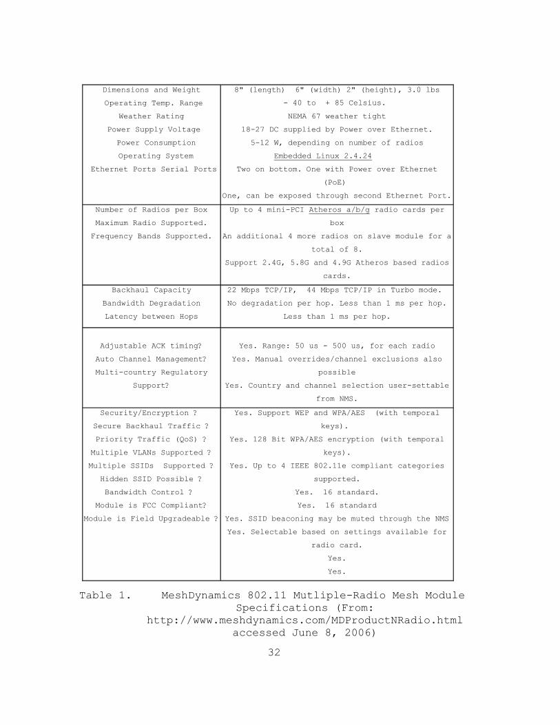
Table 1 below is a list of some of the key specifications
of the MeshDynamics 802.11 Modular Mesh devices taken
directly from the company website:
32
Dimensions and Weight
Operating Temp. Range
Weather Rating
Power Supply Voltage
Power Consumption
Operating System
Ethernet Ports Serial Ports
8" (length) 6" (width) 2" (height), 3.0 lbs
- 40 to + 85 Celsius.
NEMA 67 weather tight
18-27 DC supplied by Power over Ethernet.
5-12 W, depending on number of radios
Embedded Linux 2.4.24
Two on bottom. One with Power over Ethernet
(PoE)
One, can be exposed through second Ethernet Port.
Number of Radios per Box
Maximum Radio Supported.
Frequency Bands Supported.
Up to 4 mini-PCI Atheros a/b/g radio cards per
box
An additional 4 more radios on slave module for a
total of 8.
Support 2.4G, 5.8G and 4.9G Atheros based radios
cards.
Backhaul Capacity
Bandwidth Degradation
Latency between Hops
22 Mbps TCP/IP, 44 Mbps TCP/IP in Turbo mode.
No degradation per hop. Less than 1 ms per hop.
Less than 1 ms per hop.
Adjustable ACK timing?
Auto Channel Management?
Multi-country Regulatory
Support?
Yes. Range: 50 us - 500 us, for each radio
Yes. Manual overrides/channel exclusions also
possible
Yes. Country and channel selection user-settable
from NMS.
Security/Encryption ?
Secure Backhaul Traffic ?
Priority Traffic (QoS) ?
Multiple VLANs Supported ?
Multiple SSIDs Supported ?
Hidden SSID Possible ?
Bandwidth Control ?
Module is FCC Compliant?
Module is Field Upgradeable ?
Yes. Support WEP and WPA/AES (with temporal
keys).
Yes. 128 Bit WPA/AES encryption (with temporal
keys).
Yes. Up to 4 IEEE 802.11e compliant categories
supported.
Yes. 16 standard.
Yes. 16 standard
Yes. SSID beaconing may be muted through the NMS
Yes. Selectable based on settings available for
radio card.
Yes.
Yes.
Table 1. MeshDynamics 802.11 Mutliple-Radio Mesh Module Specifications (From:
http://www.meshdynamics.com/MDProductNRadio.html accessed June 8, 2006)

33
Some of the most important characteristics that make
these devices more reliable than other commercial products
are their advertised thermal characteristics and improved
bandwidth usage. Last year’s devices constantly
overheated, resulting in significant drops in network
performance and sometimes even a complete shutdown of the
network. However, the MeshDynamics Modules are advertised
as being able to operate in an environment with a
temperature range of between -40 and +85 degrees Celsius.
The basic mesh module (Figure 7) is capable of
supporting up to 4 Atheros-based a/b/g radios configured to
operate in either the 5.8GHz or 2.4GHz spectrum.
Figure 7. Port Numbers on Mesh Modules (From: http://www.meshdynamics.com/MDProductNRadio.html
accessed June 8, 2006)
In the multiple-radio modules, port 0 and port 1 are
designed to house the two backhaul radios. These radios
operate in the 5.8GHz radio spectrum. Port 0 houses the
uplink radio and port 1 houses the downlink radio. Port 2
is designed to house the service radio, which provides
service to wireless clients seeking to associate with the
network. If four radios are being used, port 3 provides
the option to install a scanning radio or a second service
radio. The service and scanning radios installed in ports
2 and 3 operate in the 2.4GHz radio spectrum. The majority

34
of testing done by this year’s team involved the use of
three radio units. An example is shown in Figure 8.
Figure 8. Inside View of a 3-radio MeshDynamics Mesh
Module
One of the advantages of these basic mesh modules is
that they can be configured to fit the needs of a specific
network. The 2-radio units can be used for a basic
wireless meshed backhaul network. These units can then be
upgraded (in the field) to 3-radio and 4-radio units if the
number of clients using the network increases. During the
COASTS 2006 field experiments the team was unable to test
for the maximum amount of clients that could associate with
each of the Mesh Modules. However, according to
MeshDynamics research, a multi-radio device does not suffer
from bandwidth degradation as much as a single radio device
does
(http://www.meshdynamics.com/MDPerformanceAnalysis.html).
The Mesh Modules can also be configured with different

35
power radio transmitters, operating frequencies, and
software configurations in order to meet the requirements
of the network.
The MeshDynamics 802.11 Multiple-Radio Mesh Modules
make it possible to fully exploit the available bandwidth.
Having only one radio does not allow each mesh node to send
and to receive simultaneously. However, a two- or three-
radio unit allows for operation within non interfering
channels.
The MeshDynamics 802.11 Mesh Modules are part of a
large family of MeshDynamics Structured Mesh devices. The
following two tables layout the specifications of the two
different MeshDynamics 802.11 Mesh Modules that were used
for the COASTS 2006 iteration. Table 2 gives a breakdown
of the radio configurations in each of the two MeshDynamics
Mesh Module models used by the COASTS 2006 team. Table 3
provides a more detailed breakdown of what each model
number shown in Table 2 represents. These tables were
constructed by USAF 1st Lieutenant Robert Lounsbury, an NPS
student in the Joint Command, Control, Computers,
Communications and Intelligence (JC4I) curriculum, as part
of his directed study titled, COASTS 2006 802.11 Optimum
Antenna Configuration.

36
Model Specifications
MD4350-AAIx-1110
Four slot mini-PCI motherboard Two 400mW Ubiquity SuperRange 5, IEEE 802.11a, 5.8GHz backhaul radios One 400mW Ubiquity SuperRange 2, IEEE 802.11b/g 2.4GHz service radio with basic software features
MD4325-GGxx-1100
Four slot mini-PCI motherboard Two 400mW Ubiquity SuperRange 2, IEEE 802.11b/g, 2.4GHz backhaul/service radios One 64mW 2.4GHz scanning radio with mobility software features
Table 2. COASTS 2006 MeshDynamics Mesh Module Configurations (From: Lounsbury 2006)
*Four Position Numerical Designator
Four Position Radio Configuration
Four Position Radio Type
Number of Available Mini-PCI slots (1 – 4)
Backhaul Radio (A = 802.11a, G = 802.11g)
One number per available slot (0 = 64mW, 1 = 400mW, remains “0” if radio not installed)
Number of installed radios (1 – 4)
Service Radio (B = 802.11b, G = 802.11g, I = 802.11b/g )
One number per available slot (0 = 64mW, 1 = 400mW, remains “0” if radio not installed)
Backhaul Frequency (2 = 2.4GHz, 5 = 5.8GHz)
(x = no radio) One number per available slot (0 = 64mW, 1 = 400mW, remains “0” if radio not installed)
Software Features (0 = Basic, 2 = multi-root, 5 = Mobility)
*MD represents MeshDynamics
One number per available slot (0 = 64mW, 1 = 400mW, remains “0” if radio not installed)
Table 3. MeshDynamics Mesh Module Model Number Breakdown (From: Lounsbury 2006)

37
D. ANTENNAS AND RADIOS
To clarify future chapters, this section provides
technical information about the various antennas and radios
used in this research.
As mentioned previously, one of the key
characteristics of the MeshDynamics 802.11 Multiple-Radio
Mesh Modules is the ease of configuration and the ability
to utilize multiple radios The radios can vary in
transmitted power output and frequency range. The
flexibility of the MeshDynamics modules is further enhanced
by changing the antenna configuration based upon network
performance requirements and client distribution. The
COASTS 2006 network topology was composed of ground, air,
and sea clients. As a result, various types of antennas
were used, including directional, omni-directional
sectored, and multi-polar.
Since most of the equipment, especially the MD Mesh
Module, used by the COASTS 2006 team was new, it was never
integrated in the topology configuration used during the
COASTS 2005 field experiments. As a result, it was
necessary to conduct numerous test sessions in order to
find an optimal antenna and radio configuration.
The three different radios used during testing by the
COASTS 2006 team were the Ubiquiti Networks SuperRange2
(400mW) 2.4GHz radio (Figure 9), the Ubiquiti Networks,
SuperRange 5 (400mW) 5.8GHz radio (Figure 10), and the
Winstrum (64mW) 2.4GHz radio. The radios that operate in
the 2.4GHz range were used as service and scanning radios.

38
The radios that operated in the 5.8GHz range were used as
backhaul radios, including both upstream and downstream
links.
Figure 9. Ubiquiti SuperRange2 Radio (left) and
SuperRange2 Specifications (right) (From: http://www.comnet.com.au/Ubiquiti/SR2.htm
accessed June 8, 2006)
Figure 10. Ubiquiti SuperRange5 Radio (left) and
SuperRange5 Specifications (right) (From: http://www.comnet.com.au/Ubiquiti/SR5.htm
accessed June 8, 2006)

39
Before deciding on the optimal antenna configurations,
the COASTS 2006 team tested a wide variety of different
antennas and deployment topologies. One of the
recommendations taken from the COASTS 2005 After Action
Report was to use an 8-dbi omni-directional antenna. This
antenna, seen below in Figure 11, provided the most
effective configuration during the COASTS 2005 field
experiments. Table 4 lists the key specifications of this
antenna.
Figure 11. SuperPass 8dbi Omni-directional
Antenna(left) and 8dbi Antenna Beamwidths (From: http://www.superpass.com/SPDJ6O.html accessed
June 8, 2006 )
No ITEM TYPICAL 1. Frequency Range 5250 – 5900 MHz 2. Impedance 50 Ohms 3. VSWR (or Return Loss) 1.5:1 ( or 14dB) 4. Gain 8dBi 5. Polarization Vertical, Linear 6. 3dB Horizontal Beamwidth 360 deg. 7. 3dB Vertical Beamwidth 18 deg. 8. Max. Power Input 20W 9. Connector N female 10. Size 10" x 1" 11. Housing Material Fiber-Glass 12. Temperature Range -45 to +75 C
Table 4. SuperPass 8dbi Omni-directional Antenna Specifications (From:
http://www.superpass.com/SPDJ6O.html accessed June 8, 2006)

40
Another antenna that was tested extensively by both
the COASTS 2005 and 2006 teams was the WiFi-Plus 5dbi,
multi-polar, omni-directional antenna (Figure 12 and 13).
This antenna has a high-gain, near-the-horizon, vertically
polarized signal and a dual/multi-polarized lobe that
continues up to 90 degrees elevation (Lee 2005, 40). This
antenna proved to be one of the most effective antennas
when it was used as part of the balloon payload. In COASTS
2006, this antenna was used on both the service and
backhaul radios.
Figure 12. WiFi-Plus 5dbi Antenna (From:
http://www.wifi-plus.com/images/WFP0200507tearsheet.doc accessed
June 8, 2006)
Figure 13. 5dbi Antenna Beamwidths (From:
http://www.wifi-plus.com/images/WFP0200507tearsheet.doc accessed
June 8, 2006)

41
Three other antennas were also tested:
• SuperPass 9dbi – 2.4GHz Omni-directional antenna (Figure 14)
• HyperLink 12dbi – 5.8GHz Omni-directional antenna (Figure 15)
• WiFi-Plus 13dbi – 2.4GHz and 5.8GHz Omni-directional antenna. (Figure 16)
Figure 14. SuperPass 9dbi Antenna (From:
http://www.superpass.com/SPDG8O.html accessed June 8, 2006)
Figure 15. Hyperlink 12dbi Omni-directional Antenna
(From: http://www.hyperlinktech.com/web/hg5812u_pro.php
accessed June 8, 2006)

42
Figure 16. WIFI-PLUS 13dbi Multi-Polar Antenna (From:
http://www.wifi-plus.com/images/SpecsSingleSector2.pdf accessed
June 8, 2006)
The specific configurations of antennas and radios that
were used throughout the COASTS 2006 field tests are
discussed in Chapter V of this thesis.
E. AP MESHVIEWER
It was critical to constantly monitor the status of
the network in real-time. This was accomplished using
MeshDynamics AP Meshviewer software, enabling efficient
data collection and overall network management. A sample
screenshot of MeshViewer is shown in Figure 17.

43
Figure 17. Screen Shot of AP Meshviewer (From: http://www.meshdynamics.com/WNetworkMgr.html
accessed June 8, 2006)
The characteristics that made AP Meshviewer such an
advantageous tool during COASTS 2006 field experimentation
and testing and evaluation were as follows:
• LED Status Lights: LEDs on nodes provide a composite view of overall state of the network.
• Multiple Network Tabs: Ensures that nodes mesh with only nodes in the same logical network.
• Configuration of VLAN, Security, SSID settings, including hidden SSID.
• Configuration of Radio Transmit Power Control and ACK timing on a per radio basis
• Ability to change the 2.4G service radio mode to 11b, 11b and 11g or only 11g (http://www.meshdynamics.com/WNetworkMgr.html accessed June 6, 2006).
In terms of data collection and network analysis, this
software allows users to gather information, such as board
temperatures, throughput rates, signal strength, individual
node activity, and node associations. Another beneficial

44
feature is the ability to view the network’s actual
topology, or to display it as a map. The topology view
displays how each of the nodes is connected to one other.
The map view allows the user to place a map image in the
background and actually move the nodes to where they are
located on the map. Both of these views are captured in
Figure 18.
Figure 18. AP Meshviewer Map and Topology Views (From:
http://www.meshdynamics.com/WNetworkMgr.html accessed June 8, 2006)
F. IXCHARIOT
The primary piece of software used for data collection
throughout the 2006 field experiments was Ix Chariot. The
software is a product of the Ixia company, a leading
provider of performance test systems for IP-based
infrastructure and services (http://www.ixiacom.com/product
s/display?skey=ixchariot).

45
Figure 19. Figure 19: Visual Description of How
IxChariot Runs Tests (From: http://www.ixiacom.com/products/display?skey=ixc
hariot accessed June 8, 2006)
Ixia’s IxChariot is the industry's leading test tool
for emulating real-world applications to predict device and
system performance under realistic load conditions
(http://www.ixiacom.com/products/display?skey=ixchariot).
With each test, the software sends traffic over the network
to evaluate how the network performs. The results of each
test include throughput, latency, and transaction rate
data, along with a graph that has throughput data points
plotted. Figure 19 gives a visual description of how
IxChariot runs a test.
Each testing session required the use of at least two
clients. One client’s console was running the IxChariot
software while the other client was running IxChariot
Endpoint software. The IX Chariot console can only
communicate with clients that are running the Endpoint

46
software. The console running IxChariot was positioned in
the mobile command post and the console running Endpoint
was located in the field of operations.
One of the characteristics of the IxChariot software
that made it such an advantageous tool was its ability to
provide several thousand data points over the course of one
day’s testing. This abundance of data makes it possible
for users to perform in-depth analysis of overall network
performance, as well as specifics such as, throughput,
latency, and transaction rate. The COASTS 2006 team took
advantage of this software as a data collection tool and
used the information gathered to try and optimize the
performance of the network.

47
IV. PREPARATION AND NETWORK DEPLOYMENT METHODOLOGY
A. OVERVIEW
Planning for the COASTS 2006 deployment to Thailand
began with a proposed counter-drug scenario underpinned by
key research and development components such as wireless
network technology, mini UAVs, global positioning system,
and other elements as jointly developed with the Thai
military. Subsequent to scenario development and the
configuration of supporting technologies, a network
topology and an overall test plan was generated. Coupled
with the recommendations and lessons learned from the
COASTS 2005 deployment, this year’s team generated the
topology shown in Figure 20.
Figure 20. COASTS 2006 Planned Topology

48
This network is designed to be robust, rapidly
deployable, modular, and reconfigurable to meet all the
needs of tactical, operational, theater and strategic level
decision makers in coalition environments (COASTS 2006
CONOP). The topology was designed to form a wi-fi cloud of
network coverage over the entire area of operations. This
network cloud serves as an information database that allows
all approved users to either take information from it or
put information into it. It is a C4ISR architecture that
supports air, ground, and maritime forces.
The wi-fi cloud topology incorporates seven
strategically placed MeshDynamics 802.11 Multi-Radio Mesh
Modules (wireless access points (AP)) providing
connectivity for the tactical user. One AP, designated as
the root node, was located at the north-east end of the Mae
Ngat Dam face at the tactical operations center (TOC),
three other APs were deployed along the dam face at .4 mile
intervals as intermediate ground nodes, while the remaining
three APs were deployed in the air as part of a payload
suspended to tethered helium balloons. This deployment of
APs created a meshed network designed to act as a gateway
for individual clients to share information with any and
all users simultaneously, and in real-time. The 802.11
mesh, communicating directly with the TOC, was linked to
two command and control (C2) centers – the first C2 center
was located at Wing 41 at the Royal Thai Air Force base in
Chiang Mai and the second was located north of Chiang Mai
at the Royal Thai Army Intelligence and Information Fusion
Center (IIFC) - via two separate and encrypted 802.16
links. From Wing 41, data was transferred to the Royal
Thai Air Force headquarters in Bangkok and ultimately sent
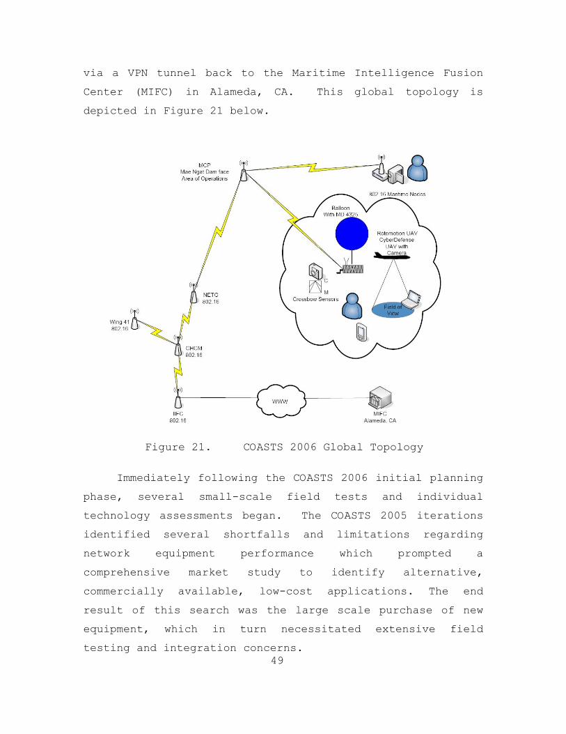
49
via a VPN tunnel back to the Maritime Intelligence Fusion
Center (MIFC) in Alameda, CA. This global topology is
depicted in Figure 21 below.
Figure 21. COASTS 2006 Global Topology
Immediately following the COASTS 2006 initial planning
phase, several small-scale field tests and individual
technology assessments began. The COASTS 2005 iterations
identified several shortfalls and limitations regarding
network equipment performance which prompted a
comprehensive market study to identify alternative,
commercially available, low-cost applications. The end
result of this search was the large scale purchase of new
equipment, which in turn necessitated extensive field
testing and integration concerns.

50
Due to constraints imposed by the larger Department of
Defense funding process, the initial stages of the COASTS
2006 field experimentation program were limited by the
availability of required hardware and software. This
inability to acquire all of the necessary networking
equipment was overcome by partially testing and evaluating
smaller subsets. The early testing and evaluation was done
in conjunction with the COASTS partner companies of
MeshDynamics and Mercury Data Systems.
It is well understood that two important governing
factors of wireless network performance are the radiated
power and the sensitivity of the antennas. Since in the US
the FCC regulates the maximum power output to one Watt,
COASTS research efforts focused more heavily on antenna
configuration. Underpinning this premise was the objective
to develop a network that was both redundant and
overlapping. To this end, a critical measure of performance
was the throughput and range limitations for each device
associated with the network. Other areas of interest
encompassed client range testing, as well as theoretical
and empirical determination of the maximum number of
clients associated with a single AP, given the operational
requirements imposed by Tactical and Remote Operations
Centers.
This chapter first discusses the methodology used for
network deployment during each of the four COASTS 2006
field testing iterations. These field tests included:
• Point Sur, CA – December 2005
• Fort Ord, CA – January 2006

51
• Fort Hunter Liggett, CA – February 2006
• Mae Ngat Dam (North of Chiang Mai, Thailand) – March 2006.
B. METHODOLOGY
Performing tests that produced reliable data, and from
which predictive models could be constructed, relied
heavily on the elements of repetition and consistency. In
addition, particular attention was given to any single
outlying data point and its effect on the data analysis of
a series of tests. To account for the impact of outlying
data points, each individual configuration resulted in
multiple iterations (in most cases six identical trials was
preferred) of the test in order to accumulate a suitably
large collection of data points. With this guideline in
place, the multiple trials consumed large amounts of test
time – certainly longer than anticipated in the planning
phase.
Antenna testing (primarily throughput and range-
testing) conducted at each field experiment was tedious.
Typically, and for each configuration evaluated, the
network consisted of a root node, a downstream node, and a
client. As with the actual network topology deployment,
the root node, positioned next to the Tactical Operations
Center (TOC), was physically wired to a Cisco 2811 router
and was powered through its power-over-Ethernet port. The
antenna being tested was then connected to the 5.8GHz
downstream, backhaul radio through the downstream antenna
port, port 1 (Figure 7). The downstream node was
configured with one 5.8GHz upstream, backhaul radio, or
with one 5.8GHz upstream, backhaul radio and one 2.4GHz
service radio. The antenna being tested was then attached

52
to the upstream radio through the upstream antenna port,
port 0 (Figure 7). Because the downstream node was
positioned far from the TOC, it was powered by an UltraLife
UBI 2590, 30V lithium ion battery. Finally, a client,
usually a laptop running the IxChariot Endpoint software,
was physically wired to another Ethernet port on the
MeshDynamics Mesh Module, which was being used as the
downstream node. As discussed in Chapter III, one common
feature of all COASTS throughput testing and evaluation
protocols mandated a client running IxChariot’s Endpoint
software in order for the throughput data to be collected.
However for range testing, the client did not have to be
running Endpoint.
Both the root node and downstream node were mounted at
the same elevation (typically between ten and twelve feet
in the air on wood or metal tripods). The position of the
root node remained constant while the downstream node was
placed on a ground vehicle so that it could be easily moved
away from the root node and down the testing field. The
client was also co-located with the ground vehicle, since
it was physically attached to the downstream node.
For each test, and to baseline the current
configuration, an initial IxChariot throughput test was run
with the downstream node stationed approximately ten feet
away from the root node. Then a separate test was run each
time that the downstream node was moved farther from the
root node at .05 and .1 mile intervals, depending on the
results of the previous trial.
In addition to specific antennae range and throughput
testing, large allocations of time were spent on testing
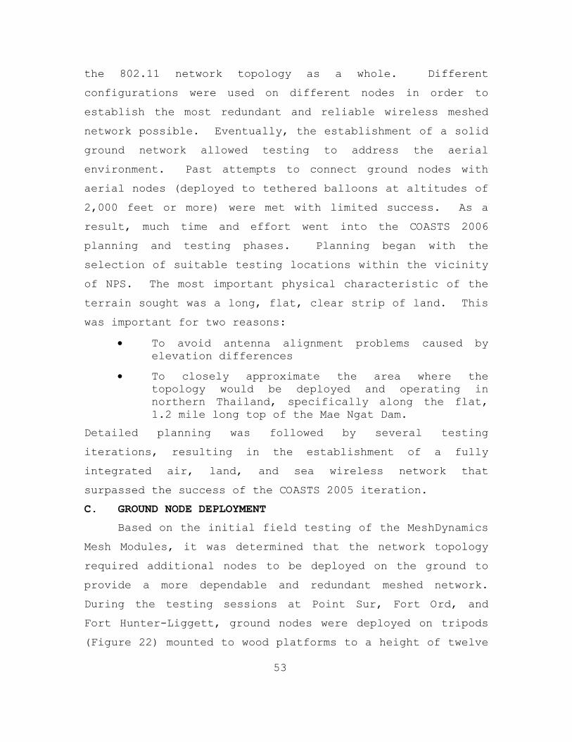
53
the 802.11 network topology as a whole. Different
configurations were used on different nodes in order to
establish the most redundant and reliable wireless meshed
network possible. Eventually, the establishment of a solid
ground network allowed testing to address the aerial
environment. Past attempts to connect ground nodes with
aerial nodes (deployed to tethered balloons at altitudes of
2,000 feet or more) were met with limited success. As a
result, much time and effort went into the COASTS 2006
planning and testing phases. Planning began with the
selection of suitable testing locations within the vicinity
of NPS. The most important physical characteristic of the
terrain sought was a long, flat, clear strip of land. This
was important for two reasons:
• To avoid antenna alignment problems caused by elevation differences
• To closely approximate the area where the topology would be deployed and operating in northern Thailand, specifically along the flat, 1.2 mile long top of the Mae Ngat Dam.
Detailed planning was followed by several testing
iterations, resulting in the establishment of a fully
integrated air, land, and sea wireless network that
surpassed the success of the COASTS 2005 iteration.
C. GROUND NODE DEPLOYMENT
Based on the initial field testing of the MeshDynamics
Mesh Modules, it was determined that the network topology
required additional nodes to be deployed on the ground to
provide a more dependable and redundant meshed network.
During the testing sessions at Point Sur, Fort Ord, and
Fort Hunter-Liggett, ground nodes were deployed on tripods
(Figure 22) mounted to wood platforms to a height of twelve
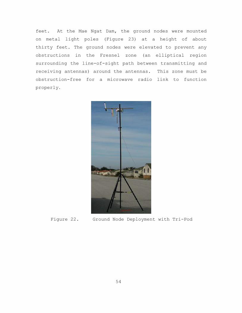
54
feet. At the Mae Ngat Dam, the ground nodes were mounted
on metal light poles (Figure 23) at a height of about
thirty feet. The ground nodes were elevated to prevent any
obstructions in the Fresnel zone (an elliptical region
surrounding the line-of-sight path between transmitting and
receiving antennas) around the antennas. This zone must be
obstruction-free for a microwave radio link to function
properly.
Figure 22. Ground Node Deployment with Tri-Pod
55
Figure 23. Ground Node Deployment on Light Post
Each of the ground nodes, with the exception of the
root node, was powered by a UBI-2590 battery, just as were
the aerial payloads. The root node, which was located next
to the Tactical Operations Center (TOC), was physically
connected to a Cisco 2811 router and powered through a
power-over-Ethernet (PoE) adapter.
D. AERIAL NODE DEPLOYMENT
The reason for deploying wireless APs into the air
with tethered helium-filled balloons was to extend the
range of the 802.11 network, allowing multiple ground-,
water-, and air-based clients to communicate with the
network. As demonstrated by the COASTS 2005 team, aerial
payloads also provide improved situational awareness of the
local environment when the payloads are equipped with
wireless IP-cameras. These cameras provide live streaming
video of the surrounding area, which can be seen by all
clients associated with the network. When using these
aerial payloads in a hostile environment, there is a higher
chance of one of the payloads being destroyed or damaged.
The loss of the aerial nodes will not cause the entire

56
wireless meshed network to fail, however the network will
lose certain ISR assets, as well as its ability to extend
to higher elevations. Whereas the COASTS 2005 team only
deployed one aerial payload into its network topology, with
limited success, the COASTS 2006 team deployed multiple
aerial 802.11 payloads simultaneously.
The past twelve months of field experimentation, both
locally and abroad, resulted in numerous lessons learned,
and coupled with the recommendations from the COASTS 2005
AAR, led to the construction of a new payload design and
configuration that was used extensively during the COASTS
2006 aerial node deployment.
1. Balloon
The following lessons learned were taken from the
appropriate sections of the COASTS 2005 AAR:
• The balloon is ideally operated during moderate winds below 10 knots. Winds greater than 10 knots must be in a consistent direction.
• This is not an all-weather balloon. Extreme heat and solar conditions causes some deterioration of balloon material.
• Maintaining a stable video image from the balloon is very difficult at low altitudes. Stability lines from the payload to the balloon tether are needed.
• The extreme heat (100+ F) and intense sunlight of Lop Buri, Thailand, also caused some deterioration of balloon material. The valve connection lost its adhesiveness during operations, which caused air to leak from the balloon. Due to the location of the valve and unfamiliarity of the proper position during operations, uncontrolled leakage of air occurred during balloon operations.
• Without wind, the Sky-Doc balloon only lifts 16.8 lbs.

57
These lessons learned led to the purchase of a relatively
low cost 10-foot, sphere-shaped, helium balloon from the
commercial company BlimpWorks (Figure 24).
Figure 24. COASTS 2006 Balloon
The advertised lift for this balloon was 23.8 pounds.
However, based on empirical testing, and to account for the
fact that the Mean Sea Level altitude of Chiang Mai is
approximately 1,200 feet, and that the density altitude is
3,000 to 5,000 feet (depending on temperature and other
conditions), the actual lift capability of a fixed-sphere
balloon is reduced when compared to the sea-level
capability on a standard day. As a result, the payload was
designed and constructed with the assumption that the
balloon had no more than 14 pounds of lift.
2. Platform
The platforms that were constructed for the COASTS
2006 field experiments were based on the design used by LT
Chris Lee during the COASTS 2005 iteration. The platforms
housed two helium tanks and the winch that was used to
raise and to lower the balloon. The platforms also served

58
as anchor points for securing the balloons at the end of
each day’s field work. Figure 25 below shows the platform,
winch, and helium tanks.
Figure 25. Platform with Helium and Winch
3. Payload
The payload (Figure 26) employed for this year’s field
experiments was based on the MeshDynamics 802.11 Multi-
Radio Mesh Modules. Throughout the various field-test
iterations, the payload was continuously reconfigured with
different radios, antennas, and cameras to find an optimal
solution for network connectivity. The different
configurations that were used for each testing session are
discussed in the remaining sections of this chapter.
The main elements of the payload included:
• MeshDynamics 802.11 Multi-Radio Mesh Module equipped with two 5.8GHz backhaul radios and one 2.4GHz service radio.
• One Axis-213 Pan-Zoom-Tilt IP Camera

59
• One Ultralife UBI-2590 Battery
• 3 Omni-directional antennas (varied throughout field testing iterations).
Figure 26. Fully Assembled Payload (From: Lounsbury
2005)
The payload design used for COASTS 2006 was designed by 1st
LT Rob Lounsbury.
E. POSSIBLE FUTURE RIVERINE OPERATIONS TOPOLOGY
The topology used by the COASTS 2006 team at the Mae
Ngat Dam had a coverage area of approximately one mile by
.5 mile. With the TOC and primary network nodes located on
the dam face, there was not much network coverage further

60
upstream along the river that runs through the Mae Ngat
Dam. Figure 27 below gives a view of the Mae Ngat Dam, as
well as, the first three miles of the river flowing from
the east of the dam.
Figure 27. Mae Ngat Dam and River with Current and
Future Network Coverage Areas
In riverine operations, one of the keys to success is
having as much situational awareness as possible. In the
COASTS 2006 network demonstration, the team was able to
establish an architecture that provided outstanding
situational awareness of the area surrounding the Mae Ngat
Dam. However, the river flowing to the dam extends over
five miles to the east of the dam. In a riverine operation
involving enemy forces that may provide more of a threat

61
than drug smugglers, the geographically limited amount of
coverage currently provided by the COASTS 2006 network may
not be enough to anticipate and prevent an attack. As a
result it may be necessary but feasible to extend the
network’s coverage further upstream. Figure 27 above shows
the current coverage area of the COASTS 2006 network, as
well as, some possible locations for the placement of more
network nodes that could extend the range of the network
further upstream.
By extending the range of the network further
upstream, riverine boat units, ground units, and UAVs would
be able to surveil and patrol larger areas and create a
greater sense of situational awareness for all of the
networks users. This new topology may also require either
a mobile operations center, or another fixed operations
center further upstream that can serve as the launch site
for boat units or UAVs that can take early action against
any possible threats.
The characteristics of the COASTS network that make it
so advantageous are that it is ad-hoc, mobile and rapidly
deployable. With these characteristics, the users gain the
ability to adjust the size or location of the network when
desired. The COASTS 2006 team took advantage of this
ability during its deployments to four different locations.
The methodology for deploying the 802.11 wireless meshed
network discussed in this chapter was modified throughout
the different field testing iterations as explained in
detail in Chapter V.

62
THIS PAGE INTENTIONALLY LEFT BLANK

63
V. FIELD TESTING ITERATIONS
The purpose of this chapter is to divide the
individual field testing iterations into terrain, weather,
objectives, topology, field tests, and results. The
overall methodology used for the field tests was discussed
previously in Chapter IV.
A. POINT SUR
The first field tests performed by the COASTS 2006
team took place at a former Navy facility located at Point
Sur, California (Figure 30).
1. Terrain
The area of operations at Point Sur (Figures 28 and
29) was a small plot of land consisting of two paved roads
within several rolling hills, surrounded by metal fencing.
The northeastern border was surrounded by the Pacific Coast
Highway and the coastal mountain range. The remaining
borders were surrounded by the Pacific Ocean. This setup
made for ideal scenery but not ideal testing conditions.
The following two figures give a better view of the area of
operations at Point Sur, CA.

64
Figure 28. Point Sur Area of Operations Terrain Contour
(From: Google Earth 2006)
Figure 29. Overhead View of Point Sur Area of
Operations (From: http://local.live.com/ accessed June 8, 2006)

65
Figure 30. Point Sur Navy Facility (left) and
Surrounding Terrain (right)
2. Weather
Throughout the course of the field testing iteration
at Point Sur, the weather conditions varied. On a majority
of the days the weather conditions were excellent, with
temperatures in the sixties, no precipitation, and minimal
wind speeds. However, the first day of testing consisted
of surface winds reaching up to around 15 knots. As a
result of these wind conditions, the COASTS team was unable
to set up the topology to include the aerial payloads on
this day. Another day of testing encountered light
precipitation and temperatures in the low fifties.
However, the COASTS team was still able to conduct testing
despite the slightly adverse weather conditions. Below,
Table 5 gives the specific weather data from the operating
period at Point Sur.

66
DATE TEMP (F) DEW POINT (F) WIND SPEED HUMIDITY MAX 55 43 12 93 3-Dec-05 MIN 39 32 0 51
AVERAGE 47 38 6 74 MAX 60 40 10 79
4-Dec-05 MIN 37 25 0 26 AVERAGE 48 32 7 58 MAX 63 46 9 83
5-Dec-05 MIN 34 27 0 26 AVERAGE 48 34 3 62
MAX 61 42 12 80 6-Dec-05 MIN 37 27 0 27
AVERAGE 49 33 8 64 MAX 57 47 8 86
7-Dec-05 MIN 37 29 0 42 AVERAGE 47 36 5 68 MAX 57 52 9 100
8-Dec-05 MIN 46 45 0 81 AVERAGE 52 46 5 90 MAX 64 44 13 93
9-Dec-05 MIN 42 32 0 35 AVERAGE 53 39 4 62
Table 5. Weather Conditions at Point Sur, CA from 03DEC –
09DEC
3. Objectives
The goals and objectives of the field experiments at
Point Sur, in terms of the 802.11 network, included the
following:
• Demonstrating the ability to mesh both aerial and ground MeshDynamics 802.11 Multi-radio Mesh Modules to create a seamless 802.11 mesh network
• Testing a variety of aerial payload configurations to ascertain optimum performance
• Ascertaining network performance with a varying number of ground-based clients.
Since Point Sur was the first of four field-test
iterations, it was also very important that the team became
familiar with all of the testing equipment. This was the
first time that the 802.11 network was deployed in the

67
field, and it was important to begin establishing an
efficient testing and evaluation procedure for future
experimentation.
4. Topology
Because of the small amount of open land and uneven
terrain, Pt. Sur did not serve as an ideal location for
testing the network topology. This topology was composed
of two aerial nodes and six ground nodes.
Figure 31. Aerial Node Deployed at Pt. Sur
The two aerial nodes (Figure 31) were configured with the
following:
• MeshDynamics 802.11 Multi-Radio Mesh Module equipped with two 5.8GHz backhaul radios and one 2.4GHz service radio
• One Axis-213 PZT IP Camera
• One Ultralife UBI-2590 Battery
• One 11.1 V Lithium-Polymer Camera Battery
• Two SuperPass 8dbi Omni-directional Antennas (Figure 11)

68
• One Hyperlink 12dbi Omni-directional Antenna (Figure 15).
The ground nodes had various configurations; the root node
was composed of:
• MeshDynamics 802.11 Multi-Radio Mesh Module equipped with two 2.4GHz service radios and one 5.8GHz backhaul radio
• One Hyperlink 12dbi Omni-directional Antenna connected to the downstream radio.
The other ground nodes were composed of:
• MeshDynamics 802.11 Multi-Radio Mesh Module equipped with two 5.8GHz backhaul radios and one 2.4GHz service radio.
• Ultralife UBI-2590 Battery
• Two SuperPass 8dbi Omni-directional Antennas
• One Hyperlink 12dbi Omni-directional Antenna.
Because the operations area was not representative of
the Mae Ngat Dam face, the setup of the ground and aerial
nodes did not resemble the planned topology that would
later be used in Thailand. The ground nodes were dispersed
around the area perimeter, with the two aerial nodes in the
center, approximately .25 miles apart.
5. Field Tests
Despite the relatively open area that was available at
Point Sur, the area most suitable for the deployment of the
mesh network still exhibited a gradual increase in
elevation (refer to Figure 32 below). This fact made range
and throughput testing for the mesh modules less than
optimal. In addition, the presence of a metal fence and
gate that ran perpendicular to the Line-Of-Sight (LOS)
between two nodes may have decreased the network
performance slightly. The individual field tests that were
performed at Point Sur are listed below in Table 6.

69
Figure 32. Sloped Road Used for 802.11 Ground Node
Testing at Point Sur, CA

70
Title Description 802.11 Test I – Ground-to- Ground
Range and Throughput w/ 12dBi Omni
Determine the maximum range possible between access points that provide acceptable throughput using 12dBi omni antennae for backhaul
802.11 Test II – Ground-to- Client
Range and Throughput w/ 12dBi and 8dBi Omni
Determine the maximum range possible between access points that provide acceptable throughput using 12dBi and 8dBi omni antennas for backhaul
802.11 Test III – Ground-to-Air
Throughput w/ 12dBi and 8dBi
Determine the throughput between ground and aerial access points w/ 12dBi and 8dBi omni antennas (Balloon elevation = 500ft)
802.11 Test IV – Ground-to-Air
Throughput w/ 12dBi and 8dBi
Determine the throughput between ground and aerial access points w/ 12dBi and 8dBi omni antennas (Balloon elevation = 1000ft)
Table 6. 802.11 Field Tests Performed at Point Sur
6. Results
The field tests at Point Sur provided a suitable
starting point for the COASTS 2006 team. Most of the
objectives for the 802.11 network were achieved; however, a
lack of equipment and terrain issues prevented the team
from achieving all of its goals.
The objectives that were achieved included:
• Establishment of a robust reliable ground 802.11 mesh network using as many as five MeshDynamics 802.11 Mesh Modules simultaneously
• Establishment and testing of an aerial 802.11 mesh network
• Testing and evaluation of other technologies such as inertial tracking and devices and shared situational awareness applications
• Integration of wireless IP cameras in conjunction with both ground and aerial nodes and then measuring the impact of streaming video across the network

71
• Testing of various antenna configurations and then measuring the impact on network performance
The most reliable piece of the 802.11 mesh network was
far and away the ground-based elements. Once the ground
nodes were configured, they were quickly deployed
throughout the operating area. The ground network’s
performance was fairly consistent, with an average
throughput of roughly ten megabits per second (mbps). The
maximum advertised throughput for the MeshDynamics 802.11
Multi-Radio Mesh Modules is 54mbps; however, at 10mbps the
ground network still supported real-time command and
control. Throughout the Point Sur field experiment, the
ground-node configuration that resulted in the best network
performance was usage of the 12dBi omni antenna affixed to
the backhaul, 5.8GHz radio on the root node and the use of
8dBi omni antennas affixed to the backhaul radios, both
uplink and downlink, on the four other ground nodes.
Once the ground network was firmly established,
streaming video from a wireless IP camera was injected onto
the network. One major advantage of the MeshDynamics Mesh
Modules was the ability to directly connect external
devices, such as the IP cameras, via a Cat5 LAN cable.
Capturing video from one camera and analyzing the effects
respective to network performance was a good starting
point, but due to time constraints, the testing of multiple
cameras was not completed and was therefore scheduled for
the next iteration of testing.
The aerial 802.11 mesh network consisted of two aerial
payloads. The payloads were configured as discussed
earlier in this chapter; with the exception that only one
payload was equipped with a wireless IP camera. This

72
topology achieved acceptable throughput between the root
node and aerial payloads for several hours, with the
balloons positioned at an elevation of approximately 1,400
feet. The root node was configured with the WiFi Plus
17dBi directional antennas affixed to the backhaul radios,
and the aerial nodes were configured with the Hyperlink
12dBi omni antennas affixed to the backhaul radios.
Unfortunately, connectivity between the ground and aerial
nodes only occurred during the first day of testing.
Ultimately the reliability of this aerial mesh network was
not demonstrated, as connectivity could not be established
during the subsequent days of testing.
This field testing iteration brought to light several
unresolved items which would require further testing in the
upcoming three iterations. A few of these items were:
• Can the ground network be robust enough to support more than one ground client, in particular the wireless IP cameras?
• What is the optimal antenna configuration for the nodes? Due to the limited selection of antennas at Point Sur this became a high priority item.
B. FORT ORD
The second iteration of the field tests took place at
Fort Ord, California, from 13 through 15 January 2006, but
due to local air restrictions, the COASTS 2006 team was not
able to fly aerial payloads for the 802.11 network testing.
As a result, testing focused exclusively on the performance
of the ground nodes. Network testing with the aerial nodes
resumed at the field testing iteration at Fort Hunter
Liggett in February 2006.
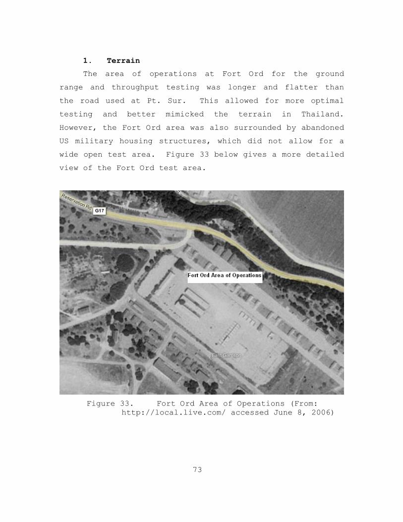
73
1. Terrain
The area of operations at Fort Ord for the ground
range and throughput testing was longer and flatter than
the road used at Pt. Sur. This allowed for more optimal
testing and better mimicked the terrain in Thailand.
However, the Fort Ord area was also surrounded by abandoned
US military housing structures, which did not allow for a
wide open test area. Figure 33 below gives a more detailed
view of the Fort Ord test area.
Figure 33. Fort Ord Area of Operations (From:
http://local.live.com/ accessed June 8, 2006)

74
2. Weather
The weather conditions at Fort Ord, CA are shown below
in Table 7. The COASTS team encountered one day of
precipitation during the three days of operations.
DATE TEMP (F) Dew Point WIND SPEED HUMIDITY
MAX 64 51 28 83 13-Jan-06 MIN 46 42 0 54
AVERAGE 55 44 16 73 MAX 54 48 18 93
14-Jan-06 MIN 44 42 0 71 AVERAGE 50 48 9 84 MAX 55 42 13 97
15-Jan-06 MIN 37 33 0 43 AVERAGE 46 39 2 76
Table 7. Weather Conditions at Fort Ord, CA from 13JAN –
15JAN
3. Objectives
The goals and objectives of the COASTS 2006 field
experiments at Fort Ord, in terms of the 802.11 network,
included the following:
• Demonstrating the ability to create a seamless 802.11 mesh network mesh on the ground using MeshDynamics 802.11 Multi-radio Mesh Modules
• Testing a variety of ground-node configurations to ascertain optimum performance
• Range testing various antennae configurations to determine the best configuration for maximum throughput.
Because of the restrictions on using aerial payloads
at Fort Ord, the team was able to focus entirely on the
802.11 ground network.
Accompanying the NPS faculty and students was Tom
Dietz, a civilian contractor from the MeshDynamics company.

75
Mr. Dietz’ extensive knowledge of wireless technology, in
particular the MeshDynamics 802.11 Multi-radio Mesh
Modules, made him invaluable to the COASTS team during the
Fort Ord testing iteration.
4. Topology
A sloping terrain had to be accounted for to ensure
the ground nodes were positioned at the same elevation.
The distances between the four ground nodes also varied in
order to prevent the buildings from obstructing the open
space that is required between nodes. The distance from
the root node to node two was approximately 0.3 of a mile,
the distance from node two to node three was about 0.12 of
a mile, and there was about 0.4 of a mile between node
three and node four. Also, because of the elevation
changes and buildings in the area, node three was
configured with the two 17 dBi directional antennas. One
of the antennas was connected to the downstream radio
(backhaul) and was pointed to the fourth node, while the
other antenna was connected to the upstream radio
(backhaul) and was pointed back to the root node. This
adjustment allowed for all four ground nodes to connect to
one another, establishing a full 802.11 ground wireless
meshed network, in spite of the obstructions in the area of
operations.
5. Field Tests
The following table (Table 8) lists and describes the
different 802.11 tests that were performed at Fort Ord.

76
Title Description
802.11 Test I – Ground-to- Ground
Range and Throughput w/ MP3dBi Vertical
Determine the maximum range possible between access points that provides acceptable throughput using vertically mounted Multi-polar 3dBi antennae for backhaul
802.11 Test I – Ground-to- Ground
Range and Throughput w/ MP3dBi Horizontal
Determine the maximum range possible between access points that provides acceptable throughput using horizontally mounted Multi-polar 3dBi antennae aimed at each other for backhaul
802.11 Test III – Ground-to- Ground
Range and Throughput w/ 12dBi Omni
Determine the maximum range possible between access points that provides acceptable throughput using vertically polarized 12dBi omni antennae for backhaul
802.11 Test IV – Ground-to- Ground
Range and Throughput w/ 2.4GHz Omni
Determine the maximum range possible between access points that provide acceptable throughput using 2.4GHz radios and 2.4GHz omni antennae for backhaul
Table 8. 802.11 Field Tests Performed at Fort Ord in
January 2006
Figure 34. Fort Ord Range and Throughput Testing Track (Blue Line)(From: http://local.live.com/
accessed June 8, 2006)
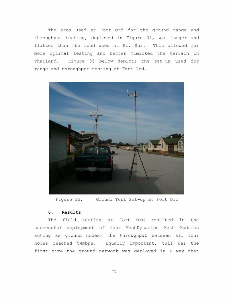
77
The area used at Fort Ord for the ground range and
throughput testing, depicted in Figure 34, was longer and
flatter than the road used at Pt. Sur. This allowed for
more optimal testing and better mimicked the terrain in
Thailand. Figure 35 below depicts the set-up used for
range and throughput testing at Fort Ord.
Figure 35. Ground Test Set-up at Fort Ord
6. Results
The field testing at Fort Ord resulted in the
successful deployment of four MeshDynamics Mesh Modules
acting as ground nodes; the throughput between all four
nodes reached 54mbps. Equally important, this was the
first time the ground network was deployed in a way that
78
resembled the topology that would be used at the Mae Ngat
Dam. Some other highlights from the testing at Fort Ord
included:
• Determined the best antenna to be used on the ground nodes, within the range limit of the operating area, was the 12dBi omni-directional antennas
• Attained 54mbps of throughput between ground nodes that were separated 0.32 of a mile and 0.4 of a mile
• Upgraded the firmware for the MeshDynamics Mesh Modules that allowed for the adjustment of the acknowledgement timing setting
The acknowledgement (ACK) time is the time that an
access point will wait for a reply from a distant access
point acknowledging that it received the previous
transmission, or that it is ready to receive a
transmission. The ACK timing is measured in milliseconds
(ms). The greater the ACK timing value, theoretically, the
greater the range over which two access points will be able
to communicate. According to MeshDynamics network
engineers, if two of the access points are set with an ACK
timing of 150ms, they should have no trouble communicating
with a few miles of separation. Because of the constrained
size of the operating area, the empiral distance limits
were not established. Similarly, the limited size of the
operating area also did not allow the team to test the
maximum range of the antennas.
Overall, the field testing at Fort Ord greatly
improved the knowledge base relative to how to best deploy
the 802.11 ground network. However, because the team was

79
not able to test the aerial payloads, some crucial issues
required resolution and were slated for the next testing
iteration at Fort Hunter Liggett. These items included:
• Testing the maximum range of the MeshDynamics Mesh Modules using various antenna configurations
• Establishing reliable ground/air connectivity
• Simulating the intended topology that would be used at the Mae Ngat Dam in Thailand.
C. FORT HUNTER LIGGETT
The third testing iteration took place at Fort Hunter
Liggett (FHL), CA, from the 10th until the 18th of February
2006. The area of operations at FHL was an almost ideal
location for 802.11 range and throughput testing, as well
as network setup.
1. Terrain
The area of operations (AO) was located on a one-mile
long, dirt runway. The change in elevation from one end of
the runway to the other did not exceed ten feet. The
surrounding area was composed of woods and mountains.
Figure 36 is a Google Earth image of the AO at FHL.
Figure 36. Fort Hunter Ligget Area of Operations (From:
Google Earth 2006)
80
2. Weather
The temperature patterns throughout the course of
field testing at FHL were fairly consistent. Early morning
temperatures averaged in the mid to low 40’s. From 0900
until around 1400, temperatures continually rose, usually
increasing to the mid to upper 70’s. With the exception of
two days of operations, the winds never exceeded five knots
during the hours of operation. When winds approached ten
knots, balloon operations were suspended because of balloon
instability. Humidity was relatively low during the day,
reaching highs of around 60% at night. There was also no
precipitation throughout the entire iteration of field
tests. Please refer to Table 9 below for specific details.
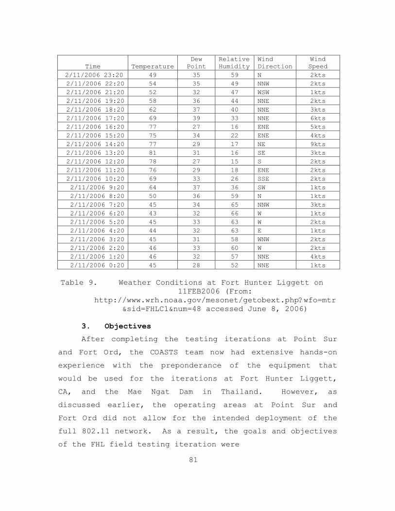
81
Time TemperatureDew Point
Relative Humidity
Wind Direction
Wind Speed
2/11/2006 23:20 49 35 59 N 2kts 2/11/2006 22:20 54 35 49 NNW 2kts 2/11/2006 21:20 52 32 47 WSW 1kts 2/11/2006 19:20 58 36 44 NNE 2kts 2/11/2006 18:20 62 37 40 NNE 3kts 2/11/2006 17:20 69 39 33 NNE 6kts 2/11/2006 16:20 77 27 16 ENE 5kts 2/11/2006 15:20 75 34 22 ENE 4kts 2/11/2006 14:20 77 29 17 NE 9kts 2/11/2006 13:20 81 31 16 SE 3kts 2/11/2006 12:20 78 27 15 S 2kts 2/11/2006 11:20 76 29 18 ENE 2kts 2/11/2006 10:20 69 33 26 SSE 2kts 2/11/2006 9:20 64 37 36 SW 1kts 2/11/2006 8:20 50 36 59 N 1kts 2/11/2006 7:20 45 34 65 NNW 3kts 2/11/2006 6:20 43 32 66 W 1kts 2/11/2006 5:20 45 33 63 W 2kts 2/11/2006 4:20 44 32 63 E 1kts 2/11/2006 3:20 45 31 58 WNW 2kts 2/11/2006 2:20 46 33 60 W 2kts 2/11/2006 1:20 46 32 57 NNE 4kts 2/11/2006 0:20 45 28 52 NNE 1kts
Table 9. Weather Conditions at Fort Hunter Liggett on
11FEB2006 (From: http://www.wrh.noaa.gov/mesonet/getobext.php?wfo=mtr
&sid=FHLC1&num=48 accessed June 8, 2006)
3. Objectives
After completing the testing iterations at Point Sur
and Fort Ord, the COASTS team now had extensive hands-on
experience with the preponderance of the equipment that
would be used for the iterations at Fort Hunter Liggett,
CA, and the Mae Ngat Dam in Thailand. However, as
discussed earlier, the operating areas at Point Sur and
Fort Ord did not allow for the intended deployment of the
full 802.11 network. As a result, the goals and objectives
of the FHL field testing iteration were

82
• To deliver a wireless mesh network, using both ground and aerial nodes, in order to enable seamless network connectivity for sensor and mobile client operations throughout the operating area
• To develop an aerial payload that provides optimum connectivity with both aerial and ground clients.
4. Topology
The ground network of the FHL network topology
consisted of four nodes, including the root node. The
nodes were separated by a distance of 0.4 mile, starting
with the root node located at the MCP. The root node was
configured with the following:
• MeshDynamics 802.11 Multi-Radio Mesh Module equipped with two 2.4GHz service radios and one 5.8GHz backhaul radio
• One Hyperlink 12dbi Omni-directional Antenna connected to the downstream radio.
The second and third ground nodes, which were positioned
0.4 and 0.8 of a mile away from the root node,
respectively, were configured with the following:
• MeshDynamics 802.11 Multi-Radio Mesh Module equipped with two 5.8GHz backhaul radios and one 2.4GHz service radio
• Ultralife UBI-2590 Battery
• One SuperPass 9dbi Omni-directional Antenna attached to the service radio
• Two Hyperlink 12dbi Omni-directional Antennas attached to the backhaul radios (upstream/downstream).
The fourth node, which was located about 1.1 miles from the
root node, was configured with the following:

83
• MeshDynamics 802.11 Multi-Radio Mesh Module equipped with two 2.4GHz service radios and one 5.8GHz backhaul radio
• One Hyperlink 12dbi Omni-directional Antenna connected to the upstream radio.
The high gain of the 17dbi sector antennas, which were
installed on the root node and on the fourth node, had both
benefits and drawbacks. The drawbacks stemmed from the
fact that the antennas had a narrow beam width, resulting
in the need to tune the antennas in the direction of the
other ground nodes carefully. The benefits of using these
sector antennas was that they had a strong enough signal
(concentrated energy) to communicate with both the balloons
and other ground nodes at long distances (up to 1.2 miles),
resulting in a solid structured mesh.
The aerial nodes that were deployed at FHL were
configured with the following:
• MeshDynamics 802.11 Multi-Radio Mesh Module equipped with two 5.8GHz backhaul radios and one 2.4GHz service radio
• One Axis-213 PZT IP Camera
• Ultralife UBI-2590 Battery
• 11.1 V Lithium-Polymer Camera Battery
• One SuperPass 9dbi Omni-directional Antenna connected to the service radio
• Two Hyperlink 12dbi Omni-directional Antennas connected to the backhaul radios (upstream/downstream).
5. Field Tests
The following table (Table 10) lists and describes the
different 802.11 tests that were performed at Fort Hunter
Liggett.
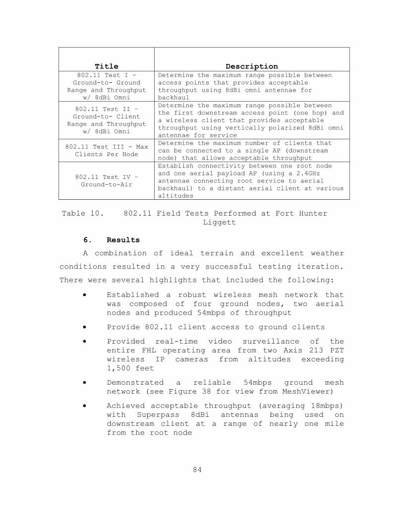
84
Title Description 802.11 Test I – Ground-to- Ground
Range and Throughput w/ 8dBi Omni
Determine the maximum range possible between access points that provides acceptable throughput using 8dBi omni antennae for backhaul
802.11 Test II – Ground-to- Client
Range and Throughput w/ 8dBi Omni
Determine the maximum range possible between the first downstream access point (one hop) and a wireless client that provides acceptable throughput using vertically polarized 8dBi omni antennae for service
802.11 Test III - Max Clients Per Node
Determine the maximum number of clients that can be connected to a single AP (downstream node) that allows acceptable throughput
802.11 Test IV – Ground-to-Air
Establish connectivity between one root node and one aerial payload AP (using a 2.4GHz antennae connecting root service to aerial backhaul) to a distant aerial client at various altitudes
Table 10. 802.11 Field Tests Performed at Fort Hunter
Liggett
6. Results
A combination of ideal terrain and excellent weather
conditions resulted in a very successful testing iteration.
There were several highlights that included the following:
• Established a robust wireless mesh network that was composed of four ground nodes, two aerial nodes and produced 54mbps of throughput
• Provide 802.11 client access to ground clients
• Provided real-time video surveillance of the entire FHL operating area from two Axis 213 PZT wireless IP cameras from altitudes exceeding 1,500 feet
• Demonstrated a reliable 54mbps ground mesh network (see Figure 38 for view from MeshViewer)
• Achieved acceptable throughput (averaging 18mbps) with Superpass 8dBi antennas being used on downstream client at a range of nearly one mile from the root node

85
• Demonstrated the ability to communicate with aerial access points at varying altitudes up to approximately 1,800 feet.
The ability to capture live streaming video from
multiple cameras demonstrated the increased capability of
the 802.11 network at FHL from the Point Sur configuration.
As discussed earlier in this chapter, the team was only
able to get streaming video from one camera during the
Point Sur field tests. Also, at Point Sur the root node
had to be pointed directly at the aerial payload in order
to achieve connectivity. However, at FHL both aerial
payloads were associated with each and every ground access
point, not just the root node. Figure 37 gives a clear
image of the video that was captured by one of the aerial
payloads used at Fort Hunter Liggett.

86
Figure 37. Screen Shot of Surveillance Video Taken by
AXIS 213 PZT Camera
Another highlight of the FHL iteration was the team’s
ability to rapidly deploy the full meshed network
consistently, and with repeatability each day. A system
was established that allowed the team to reconstitute the
network, including the four ground nodes and two aerial
nodes, across the area of operations within one hour each
morning. Figure 38 depicts a screen shot of the full
802.11 network, with each node providing the full 54mbps
throughput. This screen shot was taken throughout the

87
course of testing at Fort Hunter Liggett and was proof of
the repeatability of setting up a robust 802.11 wireless
meshed network.
Figure 38. MeshDynamics MeshViewer Screen Shot of Fort Hunter Liggett 802.11 Network
The only unresolved items that remained at the
conclusion of the Fort Hunter Liggett testing iteration
were the need to test WiFi-Plus 13dBi multi-polar antennas,
and to perform throughput testing from ground-to-air
clients at varying altitudes. Overall, the testing and
evaluation at FHL was a major success. The team was able
to deploy an 802.11 air/ground wireless meshed network that
was tactically relevant and almost identical to the one
that would be deployed at the Mae Ngat Dam in Thailand.

88
D. MAE NGAT DAM
1. Terrain
The AO for the March 2006 field tests was located on
the face of the Mae Ngat Dam, about 60 kilometers north of
Chiang Mai, Thailand. The road running along the top of
the dam provided an almost ideal location to deploy the
wireless APs. Both the north- and south-eastern sides of
the dam were heavily sloped. An aerial view of the dam and
surrounding area is shown below in Figure 39.
Figure 39. Aerial View of Mae Ngat Dam (From: Google
Earth 2006)
2. Weather
The weather conditions that the COASTS 2006
encountered during the March deployment to the Mae Ngat Dam
were extremely different from the conditions faced during
previous testing iterations. High temperatures, combined
with low winds and high humidity, resulted in challenging
working conditions. However, the severe weather conditions

89
did offer the opportunity to test the network in harsh
conditions. Table 11 details the weather conditions at the
Mae Ngat Dam during the March 2006 testing iteration.
DATE TEMP (F) WIND SPEED RELATIVE HUMIDITY MAX 101.60 8.70 63.90 21-Mar-06 MIN 79.70 0.00 23.50
AVERAGE 91.05 0.28 38.80 MAX 107.20 1.60 76.00
22-Mar-06 MIN 73.00 0.00 16.30 AVERAGE 89.86 0.02 32.76 MAX 100.10 0.00 78.30
23-Mar-06 MIN 67.90 0.00 10.30 AVERAGE 90.13 0.00 32.93 MAX 111.10 4.80 65.70
27-Mar-06 MIN 72.80 0.00 11.80 AVERAGE 96.70 0.88 24.95 MAX 109.20 7.00 70.60
28-Mar-06 MIN 64.00 0.00 13.70 AVERAGE 80.46 1.18 38.49 MAX 96.90 2.30 76.40
29-Mar-06 MIN 63.20 0.00 30.20 AVERAGE 80.56 0.12 46.52
Table 11. Weather Conditions at Mae Ngat Dam
3. Objectives
The Mae Ngat Dam iteration was the culmination of all
of the research and testing conducted during the previous
months. After the three previous California based field
experiments, the deployment to the Mae Ngat Dam had one
main objective: to constitute a reliable, fully integrated
ground and aerial wireless meshed network to enable
seamless network connectivity for sensor, UAV, and mobile
client operations throughout the operating area and
underpinning a counter-drug scenario.
This iteration included the use of all of the
individual nodes that were part of the COASTS 2006 project.
The specific nodes used were

90
• 802.11 Aerial and Ground
• 802.16
• Deny GPS
• Sensor Nets
• UAVs.
The overarching goal was to configure the network in
such a way that would allow for each node or client to
seamlessly enter and traverse the network. Once connected,
network testing and mock scenarios were conducted, and
ultimately the outputs of each individual node were to be
accessible to any other element that was connected to the
network.
4. Topology
The backbone of the ground network for the Mae Ngat
Dam field experiments consisted of four nodes, similar to
the topology that was used during the FHL iteration.
However, at one point, as many as nine MeshDynamics Mesh
Modules were deployed as ground nodes to augment the
structured mesh and to support the integration of
unattended sensors. These nodes included:
• one Root Node
• three Camera Nodes
• three Intermediate Nodes
• two Sensor Nodes.
Throughout the ten days of testing, the configuration
of the ground nodes was optimized and tuned to strengthen
network performance and reliability.
Tables 12, 13 and 14 break the configurations down
into radio use (upstream, downstream, service, or
scanning), space (5.8GHz or 2.4GHz), antennas, and radio

91
power (50mW or 400mW). Refer to Table 3 in Chapter III for
the breakdown of the three and four-letter designator
codes, such as AAII, found in column 1 of the following
tables.
MARCH 22, 2006
Radio Use Space Antennas Radio Power
Root AAII Upstream 5.8 Unused 400mW Downstream 5.8 13dBi MP Sec 400mW Service 1 2.4 13dBi MP Sec 400mW Service 2 2.4 5dBi MP 400mW Camera Node 1 AAI Upstream 5.8 8dBi Super 50mW Downstream 5.8 8dBi Super 50mW Service 2.4 5dBi MP 50mW Node 2 AAI Upstream 5.8 12dBi Large 400mW Downstream 5.8 12dBi Large 400mW Service 2.4 5dBi MP 400mW Camera Node 2 AAI Upstream 5.8 8dBi Super 50mW Downstream 5.8 8dBi Super 50mW Service 2.4 5dBi MP 50mW Node 3 AAI Upstream 5.8 12dBi Small 400mW Downstream 5.8 12dBi Small 400mW Service 2.4 5dBi MP 400mW Camera Node 3 AAI Upstream 5.8 8dBi Super 50mW Downstream 5.8 8dBi Super 50mW Service 2.4 5dBi MP 50mW Node 4 GGs Upstream 2.4 Cebrow panel 400mW Downstream 2.4 5dBi MP 400mW Scan 2.4 9dBi Super 400mW
Table 12. Mae Ngat Dam Ground Node Configurations for
22MAR2006

92
MARCH 23, 2006
Radio Use Space Antennas Radio Power
Root AAII Upstream 5.8 Unused 400mW Downstream 5.8 13dBi MP Sec 400mW Service 1 2.4 13dBi MP Sec 400mW Service 2 2.4 5dBi MP 400mW Camera Node 1 AAI Upstream 5.8 8dBi Super 50mW Downstream 5.8 8dBi Super 50mW Service 2.4 5dBi MP 50mW Node 2 AAI Upstream 5.8 12dBi Large 400mW Downstream 5.8 12dBi Large 400mW Service 2.4 5dBi MP 400mW Camera Node 2 AAI Upstream 5.8 8dBi Super 50mW Downstream 5.8 8dBi Super 50mW Service 2.4 5dBi MP 50mW Node 3 AAI Upstream 5.8 12dBi Small 400mW Downstream 5.8 12dBi Small 400mW Service 2.4 5dBi MP 400mW Camera Node 3 AAI Upstream 5.8 8dBi Super 50mW Downstream 5.8 8dBi Super 50mW Service 2.4 5dBi MP 50mW Node 4 GGs Upstream 2.4 Cebrow panel 400mW Downstream 2.4 5dBi MP 400mW Scan 2.4 9dBi Super 400mW
Table 13. Mae Ngat Dam Ground Node Configurations for
23MAR2006
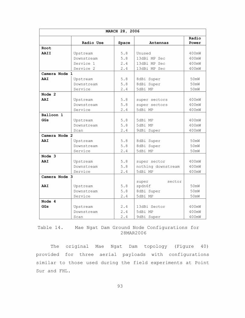
93
MARCH 28, 2006
Radio Use Space Antennas Radio Power
Root AAII Upstream 5.8 Unused 400mW Downstream 5.8 13dBi MP Sec 400mW Service 1 2.4 13dBi MP Sec 400mW Service 2 2.4 13dBi MP Sec 400mW Camera Node 1 AAI Upstream 5.8 8dBi Super 50mW Downstream 5.8 8dBi Super 50mW Service 2.4 5dBi MP 50mW Node 2 AAI Upstream 5.8 super sectors 400mW Downstream 5.8 super sectors 400mW Service 2.4 5dBi MP 400mW Balloon 1 GGs Upstream 5.8 5dBi MP 400mW Downstream 5.8 5dBi MP 400mW Scan 2.4 9dBi Super 400mW Camera Node 2 AAI Upstream 5.8 8dBi Super 50mW Downstream 5.8 8dBi Super 50mW Service 2.4 5dBi MP 50mW Node 3 AAI Upstream 5.8 super sector 400mW Downstream 5.8 nothing downstream 400mW Service 2.4 5dBi MP 400mW Camera Node 3
AAI Upstream 5.8 super sector spdn6f 50mW
Downstream 5.8 8dBi Super 50mW Service 2.4 5dBi MP 50mW Node 4 GGs Upstream 2.4 13dBi Sector 400mW Downstream 2.4 5dBi MP 400mW Scan 2.4 9dBi Super 400mW
Table 14. Mae Ngat Dam Ground Node Configurations for
28MAR2006
The original Mae Ngat Dam topology (Figure 40)
provided for three aerial payloads with configurations
similar to those used during the field experiments at Point
Sur and FHL.

94
Figure 40. Intended Mae Ngat Dam 802.11 Topology
However, due to logistic limitations, the COASTS 2006 team
was unable to obtain enough helium in Thailand to support
the operation of three balloons. As a result, the Mae Ngat
Dam network topology only included one aerial payload,
depicted in Figure 41. Below Table 15 breaks down the
configuration of the aerial payload in the same manner that
was used in Tables 12, 13, and 14.

95
22MAR2006
Radio Use Space Antennas Radio Power Upstream 5.8 5dBi MP 400mW Downstream 5.8 5dBi MP 400mW
Scan 2.4 9dBi Super 400mW
23MAR2006
Radio Use Space Antennas Radio Power Upstream 5.8 5dBi MP 400mW Downstream 5.8 5dBi MP 400mW
Scan 2.4 9dBi Super 400mW
28MAR2006
Radio Use Space Antennas Radios Upstream 5.8 5dBi MP 400mW Downstream 5.8 5dBi MP 400mW
Scan 2.4 9dBi Super 400mW
Table 15. Mae Ngat Dam Aerial Node Configurations
Figure 41. Aerial Payload Used at Mae Ngat Dam in March
2006

96
5. Field Tests
The majority of the time spent during the March
deployment to the Mae Ngat Dam was allocated to set up and
test the integrated network topology. The 802.11 network
played a central role in the scenario/demonstration that is
discussed in Appendix A-6 of the COASTS 2006 Concept of
Operations (CONOPS) (Appendix A). All of the 802.11
network assets that were mentioned in the COASTS 2006
CONOPS were deployed with the exception of three aerial
payloads.
Due to the shortage of aerial payloads, the topology
deployed at the Mae Ngat Dam was more rigorous because ten
MeshDynamics 802.11 Mesh Modules were deployed. The three
main purposes of the aerial APs were
• to extend the network into the air to serve as a gateway for other aerial clients, such as UAVs
• to provide real-time streaming video of the demonstration area
• to extend the network range for ground clients by providing an aerial AP with enhanced LOS.
However, since only one aerial AP could be launched, seven
Mesh Modules were deployed on the ground to augment the
original four APs designed to service the entire dam area.
The deployment of the ground network nodes on 30-foot light
poles required the use of a bucket truck (Figure 42) to
hoist a team member to the top of the light poles to
install the ground nodes.

97
Figure 42. Installation of Ground Nodes on light poles
at Mae Ngat Dam
Three of the ground nodes served as camera nodes in
order to provide live streaming video back to the TOC,
providing raw video data for display across the entire
network, including both the 802.11 and 802.16 portions.
The 802.11 tests that were performed at the Mae Ngat
Dam are listed and described below in Table 16.

98
Title Description 802.11 Test I – Ground-to- Ground
Range and Throughput w/ 5dBi
Determine the maximum range and throughput possible between access points that provide acceptable throughput using 5dBi omni antennae for backhaul
802.11 Test II – Ground-to- Ground
Range and Throughput w/ 13dbi and 5dBi
Determine the maximum range and throughput possible between access points that provide acceptable throughput using 13 dBi and 5dBi omni antennas for backhaul
802.11 Test III – Ground-to- Ground
Range and Throughput w/ 13 dBi
Determine the maximum range and throughput possible between access points that provide acceptable throughput using 13 dBi omni antennae for backhaul
Table 16. 802.11 Field Tests Performed at the Mae Ngat Dam
The most extensive field test performed was the
scenario run-through and demonstration that took place on
the final two days of testing. All of the field experiment
iterations that took place from December 2005 until March
2006 were in preparation for this scenario. During this
scenario run-through and demonstration, the COASTS team
successfully established a full wireless meshed network,
including all aerial and ground nodes.
6. Results
The field testing iteration at the Mae Ngat Dam proved
to be very successful in terms of achieving the team’s
objectives, as well as bringing to light some items that
required future research.
After successfully setting up a full 802.11 wireless
meshed network at Fort Hunter Liggett, replicating that
network on the Mae Ngat Dam face was highly important.
Unfortunately, due to the difficulty of acquiring helium in
Thailand, the COASTS team was only able to deploy one
aerial payload. However, this did not prevent the team
from accomplishing the following tasks:

99
• Establishing an 802.11 structured mesh network along the Mae Ngat Dam face by securing the ground nodes to 30-foot light poles
• Providing 802.11 client access to ground and air clients through the deployment of a single aerial payload
• Providing real-time video surveillance of the entire area of operations through the use of up to six separate Axis 213 PZT wireless cameras, all operating on the network at one time (one aerial-deployed camera, five ground-deployed cameras)
The ability of the network to support live video feeds
from six cameras at one time demonstrated its robustness.
The aerial-deployed camera provided surveillance coverage
of the entire area of operations. Each of the ground-
deployed camera nodes were strategically placed to provide
surveillance of particular areas of interest around the
operating area. Some of the other highlights of the Mae
Ngat Dam iteration were
• Establishing a ground network that stretched approximately 1.2 miles and remained fairly constant in performance throughout the operating period
• Communicating with two MeshDynamics Mesh Modules that were used to connect the Crossbow sensor network with the rest of the 802.11 meshed network. These two nodes were located in a valley that was approximately one-hundred feet lower in elevation than the rest of the ground network.
This is significant because it demonstrated that
proper antenna alignment can overcome the difficulties in
establishing connectivity among nodes that are located at
different elevations.

100
Ultimately the success of the COASTS team at Mae Ngat
Dam can be summarized by the screen shot shown in Figure
43. This image taken from MeshDynamics MeshViewer displays
the full wireless meshed network that was deployed during
the March deployment.
Figure 43. Screen Shot of Mae Ngat Dam 802.11 Network
on MeshViewer
This full 802.11 wireless meshed network surpassed all
of the prior accomplishments of the COASTS 2005 and COASTS
2006 teams and demonstrated the potential of the future
COASTS program.

101
VI. CONCLUSION
A. OVERVIEW
The research and field experimentation conducted over
the past two years by the COASTS team has demonstrated the
applicability of specific COTS wireless technologies.
These technologies have been developed to enable an ad-hoc
wireless meshed network that was used to support coalition
operations taking place in adverse climatic environments.
The lessons learned from the COASTS 2005 iteration allowed
the COASTS 2006 team to make major advances in this network
development.
The main objective of this thesis was to research the
overall effectiveness of the MeshDynamics 802.11 Mutliple-
Radio Mesh Modules as one of the key pieces of wireless
technology by establishing a reliable, mobile, wireless
network. Several testing sessions occurred throughout the
past year in order to prepare for the fully integrated
network demonstration that took place in March and May 2006
with the Royal Thai Armed Forces.
Because the MeshDynamics Mesh Modules purchased by the
COASTS 2006 team were different pieces of technology than
the 802.11 wireless equipment used by the COASTS 2005 team,
the initial tests done by this year’s team focused on
finding the optimal antenna and radio configurations for
the MeshDynamics Mesh Modules. Throughout the testing
iterations at Point Sur, Fort Ord, FHL, and the Mae Ngat
Dam, the team was able to establish a solid wireless meshed
network that supported various ISR assets, as well as,
ground and aerial clients. However, the performance of the

102
802.11 network was not 100 percent reliable. There were a
few instances throughout the network testing and
integration sessions in which the network became
unreliable. Usually about once a day, the network’s
throughput would suddenly degrade or one of the ground or
aerial nodes would stop communicating with the rest of the
wireless meshed network. The reason for this was unclear.
Often rebooting a node or slightly changing the direction
in which an antenna was pointed reestablished network
connectivity. However, guaranteeing a consistent
performance of the network was impossible.
However, the overall performance of the 802.11 network
exceeded the expectations of the COASTS 2006 team and did
serve its purpose by supporting the network integration
demonstration at the Mae Ngat Dam. At this stage in its
development, the COASTS team has developed a C4ISR
infrastructure that, in addition to use by Maritime
Security Forces, is also sufficient for use by law
enforcement agencies and natural disaster recovery teams.
The ability to set up an ad-hoc wireless network that
provides communications, surveillance, and overall
situational awareness capabilities is essential. However,
there is still room for improvement in terms of overall
network reliability.
B. LESSONS LEARNED
The new 802.11 technologies used by this year’s team
brought to light many new lessons learned. The primary
issues that required attention were antenna alignment and
radio configuration. The antennas that were used on each
node were chosen based on the location and purpose of the
node. For example, the best antenna to use on the root

103
node was determined to be the 13 dBi directional antenna.
The signal radiated from these antennas allowed the root
node, which was located at the TOC, to communicate directly
with the fourth ground node. Another lesson learned was
the importance of elevation effects and LOS between the
MeshDynamics Mesh Modules. The performance of the network
will degrade significantly if changes in elevation are not
accounted for with proper antenna alignment. At Fort Ord,
the COASTS team made use of directional antennas to
overcome the lack of LOS and the change in elevation
between the four ground nodes.
In regard to the set-up of the 802.11 network, there
were lessons learned that will make the future network set-
up even more efficient. Because each of the MeshDynamics
Mesh Modules have similar outer casings, placing a tag on
each module that identifies the radios that they are
configured with is important. Labeling the boxes will end
the need to open each mesh module in order to check its
configurations. Another important lesson learned was to
test each aerial payload before attaching it to the
balloons and raising them to the desired elevation. This
can be done by powering up the aerial payload, and standing
about fifty feet in front of the root node, and waiting for
it to initially connect to the wireless meshed network.
Another important lesson learned was in regard to wind
direction affecting the position of the balloons and aerial
nodes. The antennas on the root node are pointed in the
direction of the other ground nodes. The position of the
aerial nodes is also within the coverage area of the root
node’s antennas. However, there have been instances in
104
which the direction of the wind has shifted the balloons
and aerial payloads out of the coverage area of the root
node’s antennas, resulting in a loss of communication
between the ground network and the aerial nodes.
C. FUTURE RESEARCH
The success of the COASTS 2006 team has opened the
door for future research that will benefit not only future
COASTS project teams, but also the United States, Thai, and
other potential coalition military forces. In particular,
the recently formed U.S. Navy’s NECC and its new Riverine
Warfare group, which will become operational in January
2007, may be able to start using some of the technologies
that have been tested by the COASTS 2006 team. The first
mission for the U.S. Navy’s Riverine Group One will be the
surveillance and protection of the Haditha Dam, located on
the Euphrates River in Iraq. The C4ISR infrastructure that
was designed for and established at Thailand’s Mae Ngat Dam
by the COASTS team may serve as an excellent starting point
for future C4ISR infrastructures that can be used by U.S.
Riverine Forces at imminent deployment locations in Iraq
and elsewhere.
With the success of the COASTS 2006 team working in
conjunction with the Royal Thai military forces, the COASTS
2007 iteration will once again take place at the Mae Ngat
Dam in Thailand. Returning to the same location for next
year’s project will be a major advantage to the COASTS 2007
team. The procedure for network set-up, most importantly
the placement of ground and aerial nodes, has already been
established.

105
One of the major focal points for next year’s team
will be to find an optimal antenna and radio configuration
for the MeshDynamics 802.11 Mesh Modules, which will be
placed on the aerial payloads. Achieving reliable
communications between the ground and air portions of the
network is a major objective of both the COASTS team and
its Royal Thai Military Forces partners. The aerial nodes
serve as the primary platform for providing streaming video
surveillance of the area of operations. One of the major
problems faced during the field tests by this year’s team
was the inconsistency of the aerial payloads to provide
live streaming video. The factors that caused this problem
are not presently known. Whether it was degraded
performance of the MD Mesh Modules, or the Axis cameras is
still in question.
The design of the aerial payloads for this year’s
field tests proved to be sufficient in terms of being
structurally sound. However, the weight of the payloads
often came close to the lift capacity of the balloons being
used by the COASTS team. During periods of high humidity
or heavy winds, the balloon’s lift capacity was reduced and
the aerial payload could not be raised to the desired
elevation. Part of the problem was the need to power the
MeshDynamics Mesh Module and the Axis 213 PZT camera from
two different battery packs. Powering the aerial cameras
from the same power source used for the MD Mesh Modules
allowed for a smaller logistical footprint, as well as, a
lighter payload. Another reason for a lighter payload was
to provide the option of adding GPS and weather kestrel
units to each payload.

106
Another area in which future research should be
focused is on the effects of weather and environmental
conditions on the performance of the network, in particular
the MeshDynamics 802.11 Mutliple-Radio Mesh Modules.
Limited amounts of weather data were collected throughout
the course of the COASTS 2006 field tests. The
MeshDynamics Mesh Modules were used in a variety of weather
conditions; however, no conclusive data exist as to how the
various conditions affected the overall performance of the
mesh modules.
In conclusion, the continued success with the Royal
Thai Armed Forces and the formation of the U.S. Navy’s
Riverine Forces has opened the way for continued research
that can support the various missions of these
organizations. The resulting success of the COASTS 2006
team, and the head start that the COASTS 2007 team has for
next year’s network integration testing, is bound to result
in a C4ISR architecture that facilitates the rapid
dissemination of crucial information, as well as, a
communication platform that provides multiple situational
awareness capabilities in one package. This in turn will
decrease the chances of operational failure due to lack of
information and will result in increased mission success.

107
APPENDIX A. COASTS 2005 CONCEPT OF OPERATIONS
Coalition Operating Area
Surveillance and Targeting System (COASTS)
Thailand Field Experiment (May 2006)
Concept of Operations
NAVAL POSTGRADUATE
SCHOOL
MONTEREY, CALIFORNIA

108
TABLE OF CONTENTS
TABLE OF CONTENTS ............................................ 108 LIST OF FIGURES .............................................. 111 LIST OF ACRONYMS ............................................. 112 LIST OF EFFECTIVE CHANGES .................................... 116 1.0 PURPOSE ................................................. 117
1.1. BACKGROUND........................................ 117 1.1.1 NPSSOCFEP Specifics. ...................... 118 1.1.2 NPSSOCFEP Limitations. .................... 118
1.1.2.1 Sensitivities with Foreign Observers/Participants............ 118
1.1.2.2 Meteorological, Hydrographic, & Geographic Considerations......... 119
1.1.3 COASTS 2005. .............................. 119 1.1.3.1 Purpose........................... 119
1.1.4. COASTS 2006. .............................. 120 1.1.4.1 Purpose........................... 120
1.2 REFERENCES........................................ 122 1.3 SCOPE............................................. 123
2.0 OVERVIEW. ............................................... 124 2.1 CURRENT SITUATION................................. 124
2.1.1 U.S. Perspective. ......................... 124 2.1.2 Thailand Perspective. ..................... 126
2.1.2.1 Burma............................. 126 2.1.2.2 The United Wa State Army (UWSA)... 126 2.1.2.3. Shan United Revolutionary Army
(SURA)............................ 127 2.1.3 U.S. and Thai Partnership. ................ 127
2.2 SYSTEM SUMMARY.................................... 127 2.3 CAPABILITIES...................................... 128 2.4 MAJOR COMPONENTS.................................. 128 2.5 CONFIGURATIONS.................................... 135
3.0 CONCEPT OF OPERATIONS. .................................. 136 3.1 USERS............................................. 136 3.2 COASTS SUPPORT FOR PRINCIPAL MISSION AREAS........ 136
3.2.1 Thailand Requirements. .................... 139 3.2.1.1 Thailand Requirement Overview..... 139 3.2.1.2 COASTS Support to Thai
Requirements...................... 140 3.3 COASTS IMPLEMENTATION AND OBJECTIVES – PHASED
APPROACH.......................................... 140
109
3.3.1 Phase I - Work Up. ........................ 141 3.3.2 Phase II – Pt Sur Integrated Test I & II .. 142 3.3.3 Phase III – Movement to Site .............. 143 3.3.4 Phase IV – May 2006 Demonstration. ........ 143
3.3.4.1 802.11 (2.4 GHz) End-user Tactical Network.................. 144
3.3.4.2 802.16 OFDM (5.0 GHz) Backbone.... 144 3.3.4.3 802.16 (5.8 GHz) Maritime Point
to Multi-point.................... 144 3.3.4.4 Integrated Crossbow Sensors....... 144 3.3.4.5 Wearable Computing................ 145 3.3.4.6 Thai UAV.......................... 145 3.3.4.7 Thai AU-23 Aviation 802.11g
Link.............................. 146 3.3.4.8 Shared Situational Awareness
(SSA) Agents...................... 146 3.3.4.9 Tactical Operations Center (TOC)
/ Network Operations Center (NOC)............................. 146
3.3.4.10 SATCOM Link....................... 146 3.3.4.11 Network Defense................... 146 3.3.4.12 Modeling and Simulation........... 147 3.3.4.13 Micro/Mini UAVs................... 147 3.3.4.14 High-Altitude LTA Platforms....... 147 3.3.4.15 Maritime Missions................. 147
3.3.5 COASTS Critical Event Schedule. ........... 148 3.4 CRITICAL OPERATIONAL ISSUES (COIS)................ 148 3.5 MEASURES OF EFFECTIVENESS (MOE) AND MEASURES OF
PERFORMANCE (MOP)................................. 149 3.5.1 802.16 MOE / MOP .......................... 150 3.5.2 802.11 MOP / MOE .......................... 151 3.5.3 Balloon MOE / MOP ......................... 152 3.5.4 C3 Track MOE -1 ........................... 153 3.5.5 C3 Trak MOE - 2 ........................... 154 3.5.6 C3Trak MOP - 1 ............................ 155 3.5.7 C3Trak MOP-2 .............................. 156 3.5.8 Cameras MOE / MOP ......................... 157 3.5.9 Sensors MOE ............................... 158 3.5.10 Sensors MOP ............................... 159
4.0 MANAGEMENT STRATEGY. .................................... 160 4.1 PARTICIPATING ORGANIZATIONS, ROLES, AND
RESPONSIBILITIES.................................. 160 4.1.1 COASTS Oversight Group. ................... 160 4.1.2 COASTS Program Manager (PM). .............. 160 4.1.3 COASTS Operational Manager (OM). .......... 160 4.1.4 COASTS Technical Manager (TM). ............ 160

110
4.1.5 COASTS Air Marshall. ...................... 161 4.1.6 Participating Test Organizations. ......... 161
4.2 RISK ASSESSMENT, MANAGEMENT AND MITIGATION........ 161 4.3 DEVELOPMENT STRATEGY.............................. 162
5.0 TRAINING, LOGISTIC AND SAFETY. ........................... 163 5.1 TRAINING.......................................... 163 5.2 LOGISTICS......................................... 163
5.2.1 COASTS Set-Up and Demonstration. .......... 163 5.3 SAFETY............................................ 164 6.0 MODIFICATIONS..................................... 164
APPENDIX A-1. NETWORK TOPOLOGY .............................. 165 A. INTRODUCTION AND BACKGROUND....................... 165 B. 802.16 POINT TO POINT LONG HAUL COMMUNICATIONS
SUITE............................................. 165 C. 802.16 POINT TO MULTI-POINT MOBILE
COMMUNICATIONS SUITE.............................. 166 D. 802.11 WIRELESS MESHED NETWORKS................... 167 E. COMMERCIAL SATELLITE COMMUNICATIONS............... 167 F. SHARED SITUATIONAL AWARENESS APPLICATION.......... 168
APPENDIX A-2. COASTS FUNCTIONAL AREAS ....................... 172 APPENDIX A-3. NPS THESIS RESEARCH IN SUPPORT OF COASTS
2006 .................................................... 175 APPENDIX A-4. DATA COLLECTIONS .............................. 178 APPENDIX A-5. MINI-UAVS ..................................... 181 APPENDIX A-6. COASTS 2006 STORYLINE ......................... 184 APPENDIX A-7. DISTRIBUTION LIST ............................. 187

111
LIST OF FIGURES
Figure 1. COASTS 2005 Network Topology...................120 Figure 2. COASTS 2006 Topology: Mae Ngat Dam.............121 Figure 3. COASTS 2006 Global Network Topology............122 Figure 4. Thai Mobile Command Platform...................129 Figure 5. Tethered Balloon...............................130 Figure 6. Airborne camera system for balloon and/or UAVs.131 Figure 7. INTER-4 Tacticomp Handheld GPS Enabled
Networked Situational Awareness Tools..........131 Figure 8. 802.11a/b/g network Mesh Dynamics Unit.........132 Figure 9. Red Line Communications 802.16 Suite...........132 Figure 10. Rotomotion VTOL UAV............................132 Figure 11. Cyber Defense UAV..............................133 Figure 12. Helia-Kite Network Extender....................133 Figure 13. Biometric Collection Device....................134 Figure 14. Morphing Micro Air-Land Vehicle (MMALV)........134 Figure 15. COASTS Demonstration Configuration.............143 Figure 16. Critical Events Schedule.......................148 Figure 17. Risk Matrix....................................162 Figure 18. C3Trak System Diagram..........................169 Figure 19. Position sensor integration....................170 Figure 20. COASTS 2006 Personnel Design Matrix............176 Figure 21. COASTS 2006 Personnel Deployment Matrix........177

112
LIST OF ACRONYMS
AAR After Action Report
ASR Automated Speech Recognition
AUV Autonomous (Unmanned) Underwater Vehicle
AT/FP Anti-Terrorism/Force Protection
ATCD Advanced Technology Concept Demonstration
BCA Breadcrumb Administration
BKK Bangkok
C2 Command & Control
C4ISR Command, Control, Computers, Communications, Intelligence, Surveillance, and Reconnaissance
CIE Common Information Environnent
CMA Cooperative Maritime Agreement
COASTS Coalition Operating Area Surveillance and Targeting System
COC Combat Operations Center
CONOPS Concept of Operations
COTS Commercial-Off-The-Shelf
DC Direct Current
DEA Drug Enforcement Agency
DoD Department of Defense
DRDO Defence Research Development Organization
DSSS Distributed Sequence Spread Spectrum
FCC Federal Communications Commission
FLAK Fly-away Kit
FLTSATCOM Fleet Satellite Communications
GHz Gigahertz
GPS Global Positioning System
GUI Graphical User Interface
HA/DR Humanitarian Assistance/Disaster Relief

113
IEEE Institute of Electrical and Electronic Engineers
IIFC Interagency Intelligence Fusion Center
ISR Intelligence, Surveillance, and Reconnaissance
JI Jemaah Islamiyah
JIATF-W Joint Interagency Task Force West
JUSMAGTHAI Joint US Military Advisory Group Thailand
KIAS Knot Indicated Air Speed
Li-Ion Lithium Ion
LIO Leadership Interdiction Operation
LCS Littoral Combat Ship
LM Language Model
MALSINDO Malaysia Singapore Indonesia
Mbps Mega bits per second
MCP Mobile Command Post
MDA Maritime Domain Awareness
MDP-RG Maritime Domain Protection Research Group
MDS Mercury Data Systems
MIO Maritime Interdiction Operation
MOE Measures of Effectiveness
MOP Measures of Performance
MOSP Multi-Mission Optronic Stabilized Payload
NPS Naval Postgraduate School
NSW Naval Special Warfare
OFDM Orthogonal Frequency Division Multiplexing
OSD Office of the Secretary of Defense
OTH Over the Horizon
OTHT Over the Horizon Targeting
PDA Personal Data Assistant
PSYOP Psychological Operations
RF Radio Frequency
RHIB Rigid Hull Inflatable Boat

114
ROE Rules of Engagement
RTA Royal Thai Army
RTAF Royal Thai Air Force
RTARF Royal Thai Armed Forces
RTN Royal Thai Navy
SATCOM Satellite Communications
SBU Special Boat Units
SOF Special Operations Forces
SOP Standard Operating Procedure
SSA Shared Situational Awareness
SSA Shan State Army
SURA Shan United Revolutionary Army
TNT FE Tactical Network Topology Field Experiment
TTS Text to Speech
UAV Unmanned Aerial Vehicle
USA United States Army
USAF United States Air Force
USCG United States Coast Guard
USG United States Government
USMC United States Marine Corps
USN United States Navy
USPACOM United States Pacific Command
USSOCOM United States Special Operations Command
UWSA United Wa State Army
UNODC United Nations Office on Drugs & Crime
VBSS Visit, Board, Search, & Seizure
VA Voice Authentication
VOIP Voice over Internet Protocol
VLV Variable Length Verification
VM Verification Model
VUI Voice User Interface
VV Voice Verification

115
Wi-Fi Wireless Fidelity
Wi-Max Wireless
WLAN Wireless Local Area Network

116
LIST OF EFFECTIVE CHANGES
Date Revision Number
Description Point of
Contact
31OCT05 1 Document submitted to COASTS Program Manager for review
Jim Ehlert
19NOV05 2 Document submitted to COASTS Program Manager for review
Jim Ehlert
01DEC05 3 Document submitted to COASTS Program Manager for review
Jim Ehlert
22DEC05 4 Document submitted to COASTS Program Manager for review
Jim Ehlert
30DEC05 5 Document submitted to COASTS Program Manager for review
Jim Ehlert

117
1.0 PURPOSE
This document describes the FY2006 Concept of Operations (CONOPS) for the development and implementation of the Naval Postgraduate School (NPS) research program entitled the Coalition Operating Area Surveillance and Targeting System (COASTS). The COASTS field experimentation program supports U.S. Pacific Command (USPACOM), Joint Interagency Task Force West (JIATF-W), Joint U.S. Military Advisory Group Thailand (JUSMAGTHAI), U.S. Special Operations Command (USSOCOM), NPS, Royal Thai Armed Forces (RTARF), and the Thai Department of Research & Development Office (DRDO) science and technology research requirements relating to theater and national security, counter-drug and law enforcement missions, and the War On Terror (WOT). This CONOPS is primarily intended for use by the NPS and RTARF management teams as well as by participating commercial partners. However, it may be provided to other U.S. Government (USG) organizations as applicable. This document describes research and development aspects of the COASTS program and establishes a proposed timetable for a cap-stone demonstration during May 2006 in Thailand. LIMITED DISTRIBUTION: Distribution limited to the Department of Defense (DoD), U.S. DoD contractors, and to U.S. Government Agencies supporting DoD functions, and is made under the authority of the Director, DMA. Foreign governments, contractors, and military personnel contributing to the COASTS research project are included within the limited distribution per the purview of the COASTS Program Manager.
1.1. BACKGROUND.
The COASTS programmatic concept is modeled after a very successful ongoing NPS-driven field experimentation program entitled the NPS-U.S. Special Operations Command Field Experimentation Program (NPSSOCFEP). NPSSOCFEP is executed by NPS, in cooperation with USSOCOM and several contractors, and has been active since FY2002. Program inception supported USSOCOM requirements for integrating emerging wireless local area network (WLAN) technologies with surveillance and targeting hardware/software systems to augment Special Operations Forces (SOF) missions. NPSSOCFEP has grown significantly since inauguration to

118
include 10-12 private sector companies who continue to demonstrate their hardware/software capabilities, several DoD organizations (led by NPS) who provide operational and tactical surveillance and targeting requirements, as well as other academic institutions and universities who contribute a variety of resources.
1.1.1 NPSSOCFEP Specifics.
NPSSOCFEP conducts quarterly 1-2 week long complex experiments comprising 8-10 NPS faculty members, 20-30 NPS students, and representatives from multiple private companies, DoD and US government agencies. Major objectives are as follows: - Provide an opportunity for NPS students and faculty to experiment/evaluate with the latest technologies which have potential near-term application to the warfighter. - Leverage operational experience of NPS students and faculty - Provide military, national laboratories, contractors, and civilian universities an opportunity to test and evaluate new technologies in operational environments - Utilize small, focused field experiments with well-defined measures of performance for both the technologies and the operator using the technologies - Implement self-forming / self-healing, multi-path, ad-hoc network w/sensor cell, ground, air, and satellite communications (SATCOM) network components
1.1.2 NPSSOCFEP Limitations.
1.1.2.1 Sensitivities with Foreign Observers/Participants.
Certain hardware, software, and tactics/techniques/procedures (TTP’s) implemented at NPSSOCFEP are classified or operationally sensitive, and as a result sponsors have not agreed to foreign military partnerships. However, DoD requirements exist for U.S. military forces to operate in coalition environments (which serve to strengthen relationships with foreign military partners) and to execute missions globally. Since NPSSOCFEP remains primarily a US-only event, COASTS was designed to address coalition inter-operability exchange and cooperative R&D.

119
1.1.2.2 Meteorological, Hydrographic, & Geographic Considerations.
The majority of wireless network topology research conducted by the NPS has occurred in the California Central Coast area where vegetation and climate is not representative of the Pacific Area of Responsibility (AOR)—a likely deployment location for tactical or operational WLAN and surveillance/targeting technologies. Higher temperatures and humidity, as well as denser vegetation in regions like Southeast Asia will likely create WLAN and sensor performance problems. This was proven in data collected during the COASTS 2005 deployment, and will be further examined in the 2006 deployment.
1.1.3 COASTS 2005.
1.1.3.1 Purpose.
COASTS 2005 leveraged and integrated the technological expertise of NPS’s education and research resources with the science and technology and operational requirements of the RTARF. This was done using WLAN technologies (see Figure 1 next page) to fuse and display information from air and ground sensors to a real-time, tactical, coalition enabled command and control (C2) center. The additional benefit of this first COASTS field experiment was to demonstrate USPACOM commitment to foster stronger multi-lateral relations in the area of technology development and coalition warfare with key Pacific AOR allies in the WOT - results from the May 2005 demonstration were provided to representatives from Thailand, Singapore, Australia, South Korea and the U.S.
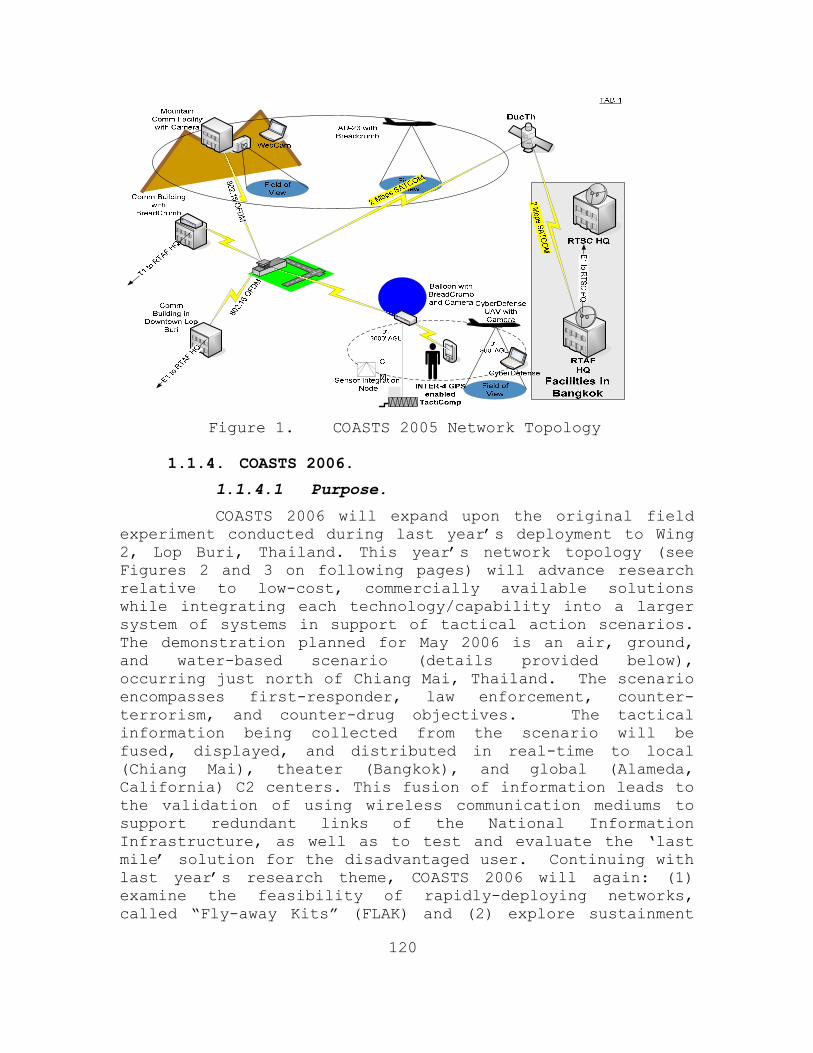
120
Figure 1. COASTS 2005 Network Topology
1.1.4. COASTS 2006.
1.1.4.1 Purpose.
COASTS 2006 will expand upon the original field experiment conducted during last year’s deployment to Wing 2, Lop Buri, Thailand. This year’s network topology (see Figures 2 and 3 on following pages) will advance research relative to low-cost, commercially available solutions while integrating each technology/capability into a larger system of systems in support of tactical action scenarios. The demonstration planned for May 2006 is an air, ground, and water-based scenario (details provided below), occurring just north of Chiang Mai, Thailand. The scenario encompasses first-responder, law enforcement, counter-terrorism, and counter-drug objectives. The tactical information being collected from the scenario will be fused, displayed, and distributed in real-time to local (Chiang Mai), theater (Bangkok), and global (Alameda, California) C2 centers. This fusion of information leads to the validation of using wireless communication mediums to support redundant links of the National Information Infrastructure, as well as to test and evaluate the ‘last mile’ solution for the disadvantaged user. Continuing with last year’s research theme, COASTS 2006 will again: (1) examine the feasibility of rapidly-deploying networks, called “Fly-away Kits” (FLAK) and (2) explore sustainment

121
considerations with respect to a hostile climatic (temperature, humidity, wind, etc.) environment. Network improvements will include the testing and evaluation of new 802.11 mesh LAN equipment, the refinement of a jointly-developed (NPS and Mercury Data Systems) 3-D topographic shared situational awareness (SSA) application called C3Trak, the integration of “satellite in a suitcase” (portable satellite communication equipment) technology, enhanced unattended ground and water-based sensors, new balloon and UAV designs, portable biometric devices, portable explosive residue detecting devices, and revised operational procedures for deployment of the network. Further explanation of the network technology can be found in Appendix A.
Figure 2. COASTS 2006 Topology: Mae Ngat Dam
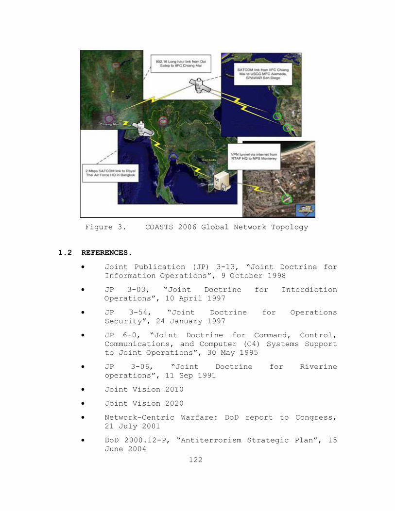
122
Figure 3. COASTS 2006 Global Network Topology
1.2 REFERENCES.
• Joint Publication (JP) 3-13, “Joint Doctrine for Information Operations”, 9 October 1998
• JP 3-03, “Joint Doctrine for Interdiction Operations”, 10 April 1997
• JP 3-54, “Joint Doctrine for Operations Security”, 24 January 1997
• JP 6-0, “Joint Doctrine for Command, Control, Communications, and Computer (C4) Systems Support to Joint Operations”, 30 May 1995
• JP 3-06, “Joint Doctrine for Riverine operations”, 11 Sep 1991
• Joint Vision 2010
• Joint Vision 2020
• Network-Centric Warfare: DoD report to Congress, 21 July 2001
• DoD 2000.12-P, “Antiterrorism Strategic Plan”, 15 June 2004

123
• DoD 2000.12, “US Navy Instruction Antiterrorism/Force Protection(AT/FP)”, 13April 1999
• COASTS Concept of Operations 2005
• COASTS OPORD, March 2005
• COASTS OPORD, April 2005
• National Strategy for Combating Terrorism, February 2003
• National Security Strategy, September 2002
• National Strategy for Maritime Security, September 2005
• Challenge for a New Era: Chief of Naval Operations Guidance for 2006, September 2005
• COMSECONDLFT message (DTG 041359Z OCT 05)
• United Nations Office of Drugs & Crime (UNODC) “Strengthening Law Enforcement in Eastern Asia” 26 November 2005
• United Nations Office of Drugs & Crime (UNODC) World Drug Report 2005
1.3 SCOPE.
This concept of operations (CONOPS) applies to all aspects of the COASTS project from date of issue through the May 2006 Thailand-based demonstration. This document is intended to provide critical information regarding the planning and execution of all aspects of the FY2006 field experimentation program. Additionally, this CONOPS provides a technical and tactical framework for complex system demonstrations used in coalition environments. This document will cover the use of COASTS as a stand-alone or networked capability focused on security mission profiles that can be enhanced by the employment of COASTS technologies.

124
2.0 OVERVIEW.
2.1 CURRENT SITUATION.
2.1.1 U.S. Perspective.
The risk of asymmetric threats to U.S. national security has outpaced the danger of traditional combat operations against a first-tier opposing military force. National security requirements are increasingly focused on facing non-military, non-traditional, asymmetric threats: piracy, terrorism, narcotics smuggling, human trafficking, weapons of mass destruction, and other transnational threats. Furthermore, with the always accelerating movement of globalization stretching U.S. interests further away from domestic borders, the national security issues of allies and other friendly nations are as vital to the U.S. as American domestic security issues. Last year in Sacramento, California over 73,000 “Yaa Baa” (crazy medicine) methamphetamine pills were confiscated by law enforcement. Yaa baa is produced primarily by the United WA State Army (UWSA), an ethnic insurgency force operating within the Burmese portion of the Golden Triangle region of Southeast Asia. These drugs were cultivated in the Golden Triangle, passed across the borders of multiple nations in Southeast Asia, and across the Pacific Ocean through various other international harbors such as Hong Kong or Singapore, as well as at least one domestic U.S. harbor. As easily as these drugs move into the interior of America, so could any multitude of other national security threats such as chemical and biological weapons of mass destruction. Numerous law enforcement, corporate and bi-lateral, multilateral, and international governmental initiatives are attempting to address these security issues on a variety of levels. JIATF-W is constructing data/intelligence fusion centers like the Inter-agency Intelligence Fusion Center (IIFC) in Chiang Mai, Thailand to enable joint and coalition intelligence collection for combined multi-national operations. The Regional Maritime Security Initiative (RMSI) and Cooperative Maritime Agreement (CMA) Advanced Technology Concept Demonstration (ATCD), focus on transnational open ocean counter-piracy and counter-terrorism, and investigate the formulation of

125
more intelligence fusion centers and multilateral coastal patrolling agreements, i.e. MALSINDO respective to the Straits of Malacca. The importance of a coalition-oriented focus for modern Maritime Domain Awareness and Protection operations is not lost on U.S. combatant commanders. In a recent naval message, all numbered fleet commanders stated their number one Command, Control, Computers, Communications, Intelligence, Surveillance, and Reconnaissance (C4ISR) requirement is improved coalition communications. Current and future operational capabilities are tightly tied to improved interoperability with U.S. allies in the operational theater. As reflected by the increasing number of requests to NPS from foreign partners, there is an immediate requirement for low-cost, state-of-the-art, real-time threat warning and tactical communication equipment that is also rapidly scaleable based on operational considerations. This issue has become especially apparent in the face of the overwhelming mission requirements placed on US forces conducting the WOT. The WOT extends globally where nations are engaged in direct action against numerous forces employing asymmetric tactics. In Thailand, the separatist insurgency in the southern provinces is connected to various transnational terrorist organizations which have struck against both the U.S. and its allies, to include both the Jemaah Islamiyah (JI) and Al-Qaeda. Further exacerbating the above situation, most current tactical systems lack the capability to rapidly enable a common information environment (CIE) amongst air, surface, and sub-surface entities via a self-forming, self-authenticating, autonomous network. Although commercial-off-the-shelf (COTS) technologies exist that can satisfy some of these requirements, these same technologies typically do not meet all of the DoD and coalition partner requirements associated with WOT and other security missions. Hence a central role of the COASTS field experimentation program is to demonstrate that NPS, in conjunction with coalition partner R&D organizations, can integrate COTS capabilities into a larger system of systems to potentially satisfy technical and tactical mission requirements.

126
2.1.2 Thailand Perspective.
The Golden Triangle Region of Southeast Asia, which includes the border regions of Thailand, Laos, Myanmar, and China, cultivates, produces, and ships enough opium and heroin to be second only to Afghanistan as a global production region. Furthermore, the Western portion of the Golden Triangle, located along most of the Burmese border with Thailand, is the largest yaa baa methamphetamine producing region in the world. Over one million addicts of yaa baa currently reside in Thailand.
2.1.2.1 Burma
Burma remains the world’s second largest producer of illicit opium with an estimated production of 292 metric tons in 2004. It is estimated that less than 1% of Burma's annual opium production is intercepted - the rest is smuggled out through China or Thailand onto the world market. Perhaps more significant, Burma and the Golden Triangle is the largest methamphetamine-producing region in the world. A 1999 survey of 32 of Thailand’s 76 provinces showed that nearly 55 percent of youths in secondary and tertiary education were using methamphetamines. Not surprisingly, Thailand views the opium and methamphetamine production of the Golden Triangle as a threat to national security and is eager to stem the flow of these drugs across its national borders.
2.1.2.2 The United Wa State Army (UWSA).
The remote jungles that divide Burma and Thailand are controlled by the UWSA, a powerful militant organization comprised from the Wa ethnic group. They have a historic reputation as a savage people; in fact some tribes practiced headhunting as late as the 1970’s. The Wa, serving as the primary fighting force of the Burmese Communist Party (BCP) until the BCP’s disintegration in 1988, took over the BCP’s drug operations and expanded upon them. The UWSA is, a well-equipped military force of approximately 20,000 soldiers, and is the largest drug-producing and trafficking group in Southeast Asia, producing heroin, methamphetamine, and possibly Methylenedioxy Methamphetamine (MDMA), or “Ecstasy”.. The UWSA buys opium from the Kokang Chinese, the Shan United Revolutionary Army (SURA), and others to use in their increasing number of refineries – currently estimated at
127
more than 50. The Southern Military Region of the UWSA is located in the Mong Yawn Valley near the Burma–Thailand border. Involved in the drug trade for decades, the Wa has increasingly switched to the production of methamphetamine pills due to international pressure to cut opium production. Due to increasing friction between the UWSA and the Burmese government - because of law enforcement efforts and greater power sought by regional Communists - there has been a significant increase of violence and traffic across the Thai border. As a result, a coalition effort consisting of Thai and U.S. forces was created in the Burma-Thailand border area of the Golden Triangle.
2.1.2.3. Shan United Revolutionary Army (SURA).
Competing with the Wa in the drug smuggling activity is the Shan ethnic group in cooperation with the Shan United Revolutionary Army (SURA). The SURA contains approximately 1,500 ethnic Shan soldiers and is one of the few remaining ethnic insurgent groups that have not agreed to a cease-fire arrangement with the Burmese Government. Recent reporting indicates that the SURA is collecting taxes from Shan traffickers and is forcing farmers to grow opium. Due to hostilities with the Wa in Burma, over 200,000 Shan refugees have crossed into Thailand since 2000 where most end up as illegal laborers.
2.1.3 U.S. and Thai Partnership.
It is the intent of the COASTS field experimentation program to demonstrate TTPs that: (1) potentially reduce or mitigate drug trafficking across the Thai-Burma border, (2) provide actionable information (real-time) to local, regional, and strategic level decision-makers, and (3) shorten the sensor-to-shooter cycle.
2.2 SYSTEM SUMMARY.
COASTS is an individual and small unit network-capable communication and threat warning system using an open, plug-and-play architecture, which is user-configurable, employing air balloons, wireless ad-hoc networks, UAVs, SSA software applications, biometrics capabilities, portable and fixed ground and water based integrated sensors, and personnel equipped with Tacticomp/Antelope or similar PDAs, all communicating via wireless network technology.

128
2.3 CAPABILITIES.
COASTS 2006 provides a mobile field experiment bed environment for U.S. and Thailand in support of R&D, integration, operational testing, and field validation of several emerging wireless technologies and equipment suites. The following research elements will be addressed:
• 802.11 b Distributed Sequence Spread Spectrum (DSSS)
• 802.11a/g Orthogonal Frequency Division Multiplexing (OFDM)
• 802.16 OFDM (Stationary)
• 802.16 OFDM (Mobile)
• SATCOM
• Situational Awareness Overlay Software
• Wearable Computing Devices
• Air, Ground, and Water Integrated Sensors
• Mobile C2 Platforms
• Unmanned Aerial Vehicles (UAVs) (Fixed wing)
• UAVs (Rotary wing)
• Unmanned Multi-environment micro vehicles
• Ultra-wide Band Integrated Sensors
• Deny-GPS Inertial Gyro technology
• Network Security Applications
• Compression software applications
• Biometrics applications
2.4 MAJOR COMPONENTS.
While the final configuration of the COASTS 2006 system may evolve further, the following core elements represent the major system components:
• Supplied by Thailand:
• Chiang Mai IIFC
• Lighter-than-air Vehicle (LTAV)

129
• L-39 Fighters (2)
• Royal Thai Air Force (RTAF) Unmanned Aerial Vehicles (UAV)
• Mobile Command Platform (MCP) – Figure 4
• Wing 41 facilities
• AU-23 configured with 802.11g connectivity
• Royal Thai Army (RTA) interdiction squad
Figure 4. Thai Mobile Command Platform
• Supplied by NPS:
• Situational awareness common operating picture (SA COP) systems
• Tethered balloons and associated hardware – Figure 5
• Airborne camera system for balloon and/or UAVs – Figure 6
• Wearable Computing Devices (INTER-4 Tacticomp) – Figure 7

130
• Three (3) laptops for use in the NMC
• Three (3) Modular PCs (Antelope)
• 802.11a/b/g network devices – Figure 8
• 802.16 OFDM network devices – Figure 9
• Deny GPS
• Rotomotion UAV – Figure 10
• CyberDefense UAV – Figure 11
• Helia-Kite Network Extender – Figure 12
• Network Security Applications
• Small boat FLAKs
• Biometric devices – Figure 13
• Morphing Micro Air-Land Vehicle (MMALV) – Figure 14
Figure 5. Tethered Balloon

131
Figure 6. Airborne camera system for balloon and/or UAVs
Figure 7. INTER-4 Tacticomp Handheld GPS Enabled
Networked Situational Awareness Tools
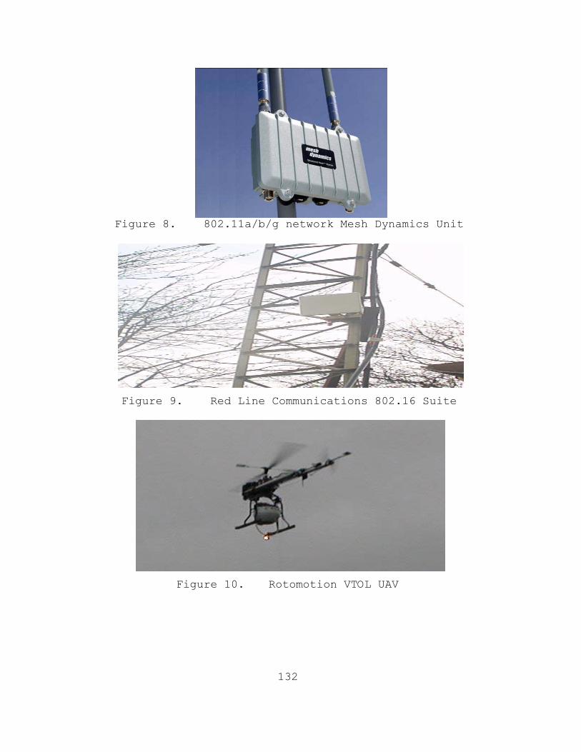
132
Figure 8. 802.11a/b/g network Mesh Dynamics Unit
Figure 9. Red Line Communications 802.16 Suite
Figure 10. Rotomotion VTOL UAV
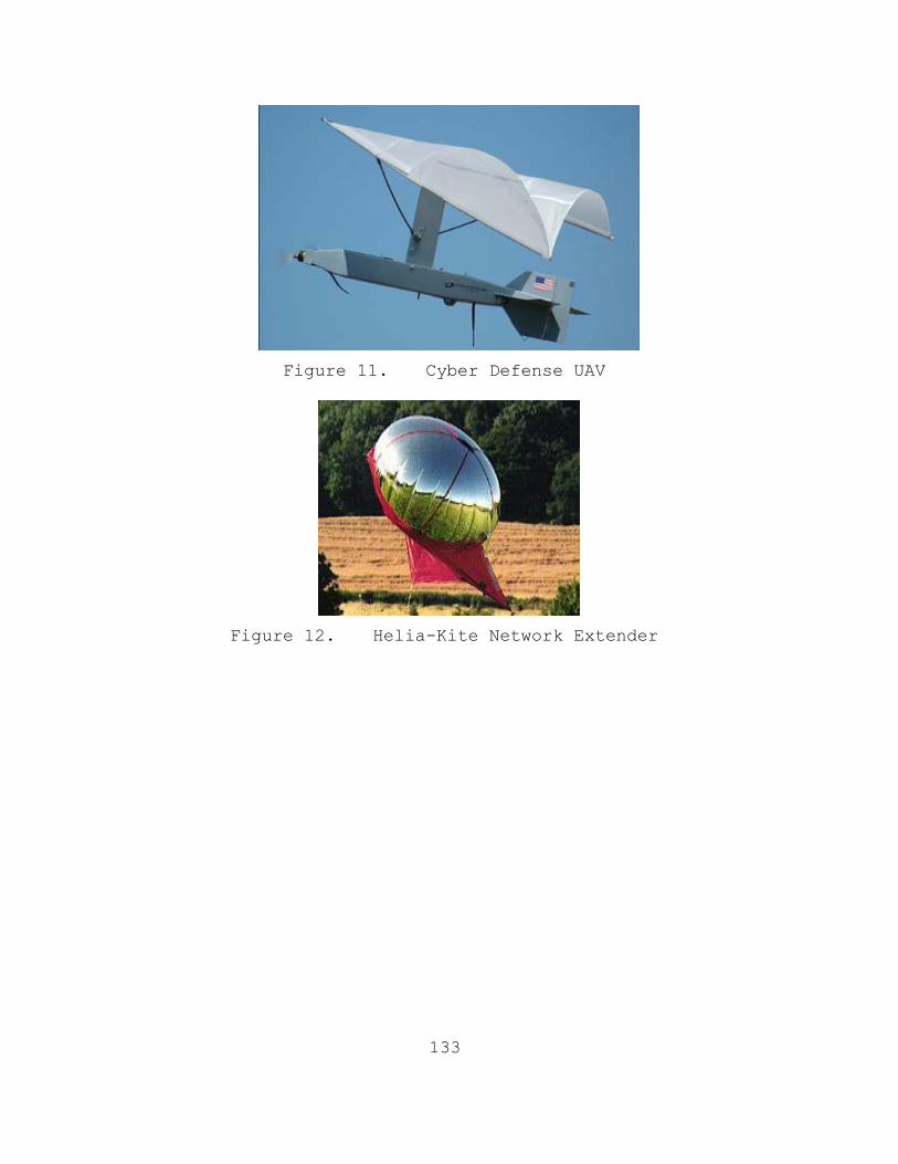
133
Figure 11. Cyber Defense UAV
Figure 12. Helia-Kite Network Extender
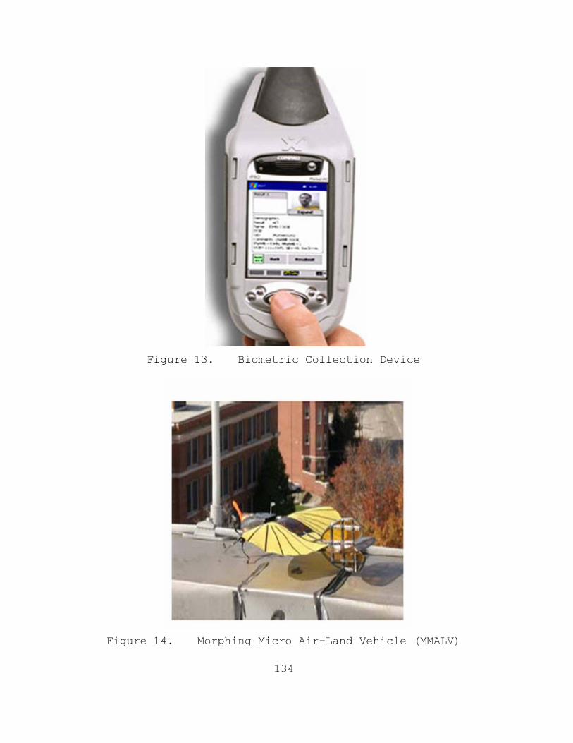
134
Figure 13. Biometric Collection Device
Figure 14. Morphing Micro Air-Land Vehicle (MMALV)

135
2.5 CONFIGURATIONS.
The May 2006 COASTS demonstration will have four basic configurations: (1) a command, control, collection, and communication suite; (2) a threat warning system; (3) an intelligence collection system; and (4) a Global Law Enforcement Interdiction database.

136
3.0 CONCEPT OF OPERATIONS.
3.1 USERS.
Generally, the COASTS 2006 participants will focus on creating an international interaction mechanism for U.S. military forces, to include NPS, to collaborate with Thailand research & development organizations and military forces to support WOT objectives and internal/external Thai security requirements. The primary users during the May 2006 demonstration will be the military and civilian NPS students and faculty, JIATF-W personnel, JUSMAGTHAI personnel, and various units from the RTARF. Secondary users may include members of the Singapore Armed Forces (SAF), Malaysian Maritime Enforcement Agency (MMEA), Japanese Self Defense Force (JSDF), Republic of the Philippines Army, and the Australian Army. Tertiary users will be the various vendors providing equipment and technical expertise to include Cisco Systems Inc., Redline Communications, Mercury Data Systems, CyberDefense Systems, Roto-motion Inc, Identix, and INTER-4. Specific vendor contributions shall be discussed in the Appendix section of this document. The NPS, RTARF, and vendor team will integrate COASTS into a system to facilitate surveillance and monitoring of simulated “areas of interest”. 3.2 COASTS SUPPORT FOR PRINCIPAL MISSION AREAS.
As per Joint Doctrine, COASTS will directly support organizing, training, and equipping U.S. military forces and the RTARF in nine principal mission areas: Direct Action (DA): The primary function of COASTS during DA missions is to provide Force Protection. DA missions are typically short-duration, offensive, high-tempo operations that require real-time threat information presented with little or no operator interface. COASTS will augment other capabilities in direct support of DA from an over-watch position. COASTS in support of DA will target collection to support threat warnings relevant to that specific operation and provide automated reporting to the Tactical Operations Center (TOC) for potential threats relevant to a specific mission. COASTS may also be used as the primary source of threat information in the absence of other

137
capabilities. Threat information presented by COASTS is intended to be relevant, real-time or near real-time, and within the area of operation. Tactical Reconnaissance (TR): The primary purpose of a TR mission is to collect information. COASTS will augment other capabilities to obtain or verify information concerning the capabilities, intentions, locations, and activities of an actual or potential adversary. COASTS will support the full range of information and communication functions. COASTS will support operators with the rapid collection, processing, analysis, and dissemination of information. COASTS will analyze how performance in this mission is influenced by meteorological, hydrographic, and geographic considerations. Foreign Internal Defense (FID): COASTS will assist Host Nation (HN) military and paramilitary forces, with the goal to enable these forces to maintain the HN’s internal stability. Combating Terrorism (CBT): COASTS will support CBT activities, to include anti-terrorism (defensive measures taken to reduce vulnerability to terrorist acts) and counterterrorism (offensive measures taken to prevent, deter, and respond to terrorism), conducted to oppose terrorism throughout the entire threat spectrum. Civil Affairs (CA): COASTS will assist CA activities in peacetime to preclude grievances from flaring into war and during hostilities to help ensure that civilians do not interfere with operations and that they are protected and cared for in the combat zone. Counter-proliferation of Weapons of Mass Destruction (WMD): COASTS will assist traditional capabilities to seize, capture, destroy, render safe, or recover WMD. COASTS can provide information to assist U.S. military forces and coalition partners to operate against threats posed by WMD and their delivery systems. Information Operations (IO): COASTS can augment actions taken to affect adversary information and information systems while defending one’s own information and
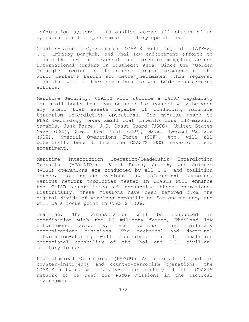
138
information systems. IO applies across all phases of an operation and the spectrum of military operations. Counter-narcotic Operations: COASTS will augment JIATF-W, U.S. Embassy Bangkok, and Thai law enforcement efforts to reduce the level of transnational narcotic smuggling across international borders in Southeast Asia. Since the “Golden Triangle” region is the second largest producer of the world market’s heroin and methamphetamines, this regional reduction will further contribute to worldwide counter-drug efforts. Maritime Security: COASTS will utilize a C4ISR capability for small boats that can be used for connectivity between any small boat assets capable of conducting maritime terrorism interdiction operations. The modular usage of FLAK technology makes small boat interdictions ISR-mission capable. Junk Force, U.S. Coast Guard (USCG), United States Navy (USN), Small Boat Unit (SBU), Naval Special Warfare (NSW), Special Operations Force (SOF), etc. will all potentially benefit from the COASTS 2006 research field experiment. Maritime Interdiction Operation/Leadership Interdiction Operation (MIO/LIO): Visit Board, Search, and Seizure (VBSS) operations are conducted by all U.S. and coalition forces, to include various law enforcement agencies. Various network topologies tested in COASTS will enhance the C4ISR capabilities of conducting these operations. Historically, these missions have been removed from the digital divide of wireless capabilities for operations, and will be a focus point in COASTS 2006. Training: The demonstration will be conducted in coordination with the US military forces, Thailand law enforcement academies, and various Thai military communications divisions. The technical and doctrinal information-sharing will contribute to the coalition operational capability of the Thai and U.S. civilian-military forces. Psychological Operations (PSYOP): As a vital IO tool in counter-insurgency and counter-terrorism operations, the COASTS network will analyze the ability of the COASTS network to be used for PSYOP missions in the tactical environment.

139
3.2.1 Thailand Requirements.
3.2.1.1 Thailand Requirement Overview.
Thailand has a 2100 kilometer border with Burma that requires its military assets to patrol, as well as to provide surveillance, monitoring and targeting to combat drug smugglers and human traffickers from entering the country via Burma. This illicit drug smuggling/human trafficking problem is significant for both Thailand and the U.S. as these activities may potentially support financing and operations of international terrorist organizations.
In addition, some of the illegal drugs that
successfully evade Thailand’s security infrastructure are ultimately taken to the U.S. via containerized shipping through the Straits of Malacca and Singapore Straits. The RTAF has been assigned the responsibility of aerial patrols of the Thailand/Burma border areas while the Royal Thai Army (RTA) 3rd Army maintains cognizance for ground–based security and surveillance.
Likewise, the recent difficulties in the southern
regions of Thailand pose potential serious security concerns. In an attempt to de-escalate tensions RTARF assets, most specifically the RTA 4th Army, have been deployed to the region. Continued difficulty, or an escalation in unrest, might lead to instability along the border as well as impacting the stability postures of other nations within the region.
The insurgency in the Southern Provinces has
greatly affected Thailand’s national security. Consistent asymmetric attacks from insurgents have taken a significant toll on the Thailand military forces. Increasing both ground and maritime security through more capable ISR will enable Thailand to reduce asymmetric attacks against civilian and military targets.
Finally, Thailand has been engaged in efforts,
primarily in the Gulf of Thailand and surrounding territorial waters, to mitigate small boat activity involved in the illegal distribution of weapons and ammunition.

140
3.2.1.2 COASTS Support to Thai Requirements.
The RTARF has previously approached NPS for collaboration using UAVs and related surveillance/targeting technologies to augment their land and maritime border patrolling resources. The RTARF is considering using UAV’s and sensor meshes to help control their northern and southern borders. 3.3 COASTS IMPLEMENTATION AND OBJECTIVES – PHASED
APPROACH.
The overall COASTS program uses a phased spiral development to implement the Thailand-based demonstration. Phase I: This initial phase will consist of the integrated demonstration (Test I) at Point Sur, California from 5-9 December, 2005. The NPS COASTS team will use the Point Sur test as a reduced-scale baseline in support of the deployable COASTS network. Phase II: Following the 2005-2006 holiday break, the COASTS Program Manager will attend a mid-planning conference with the Thai leadership in Bangkok and Chiang Mai, Thailand on January 23-27, 2006. In addition, the 802.16 Wi-max link between the Joint Operations Area (Mae Ngat Dam) and the IIFC will be constructed and tested. Based on the information and decisions derived from this conference, a second integrated test (Test II) will be conducted at Point Sur on February 6-10, 2006. Equipment, network, and scenario implementation decisions will be finalized at the conclusion of Test II. The final planning conference will be conducted on February 20-24, 2006 in Bangkok, Thailand. Phase III: The third phase will commence with the complete COASTS system deployment from NPS to Thailand, and subsequent set-up and testing, occurring in late March 2006 (exact dates are TBD, but are expected to be March 20-31, 2006). The primary focus of this phase will be to identify and mitigate any shortfalls relating to administration, deployment, and operation of the COASTS network. Upon completion of successful testing and operation, the COASTS network will be disassembled and stored at JUSMAGTHAI and/or Wing 41.

141
Phase IV: This fourth and final phase will consist of the actual operational demonstration, occurring May 22-31 2006. Since the timing of the COASTS demonstration is in parallel with the COBRA GOLD 2006 Command Post Exercise (CPX), COBRA GOLD and senior RTARF leadership will be available to receive the COASTS executive summary and observe the actual system demonstration.
3.3.1 Phase I - Work Up.
Phase I consists of the following. Milestones Completed:
• Conducted a July 2005 After Action Report (AAR) debrief for U.S. and Thai COASTS 2005 participants, to include full disclosure on all pertinent issues concerning the deployment and demonstration testing.
• Conducted an August 2005 site survey that included Wing 41, the Mae Ngat Dam Joint Operations Area (JOA), and the IIFC. Baseline signal readings were taken at the Mae Ngat Dam as well as GPS positions for future network asset placements.
• Completed an October 2005 concept development conference at the NPS with RTARF officers.
Major Issues Remaining: • Operational and Technical details of the LTAV?
• Cross-channel interference from the RTAF 802.11g capability?
• Availability of the MCP?
• Power at the Mae Ngat Dam?
• Lack of thesis students for key operational/technical areas?
• GPS positions of cell-phone towers in Chang Mai, Thailand?
• Baseline tests during the Pt Sur Integrated tests?

142
• Secondary tests during the second Pt Sur Integrated tests?
• Mini-test schedules and locations
• MIFC VPN planning meeting
• Biometric planning meeting
• NSG Monterey training & operational schedule
3.3.2 Phase II – Pt Sur Integrated Test I & II
Phase II entails the collection of individual nodal and integrated tests required to prepare for the COASTS deployment to Thailand in March and May 2006. On December 3-9, 2005, COASTS members conducted the first integrated test of equipment at PT Sur California. These tests included:
• Initial Network Construction
• 802.11 antenna configuration, range, and power testing
• Deny GPS testing
• Baseline Data Collection
• Initial Logistics management
• Mobile and Stationary 802.16 OFDM testing
Overall, the completed tests identified further research avenues, equipment requirements, and logistics needs the team must assess prior to the deployment to Thailand in March 2006. Over the Holiday break, individual node leaders will conduct tests to finalize their baseline testing parameters prior to the second and third integrated tests. These mini-tests will focus on antenna configuration, power management, and the removal of extraneous material prior to deployment. The first integrated tests to follow these will be conducted at the former Fort Ord North of the Naval Postgraduate School in Monterey, CA. The next integrated test will be of the final deployable network in February 2006.
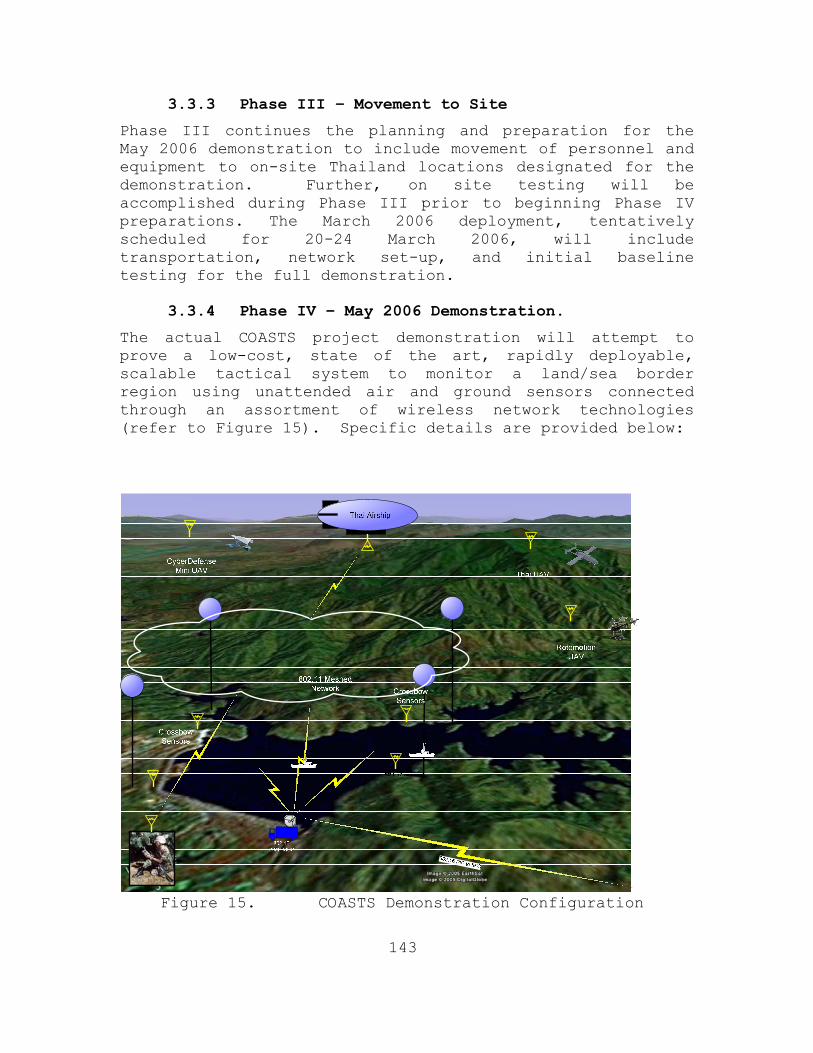
143
3.3.3 Phase III – Movement to Site
Phase III continues the planning and preparation for the May 2006 demonstration to include movement of personnel and equipment to on-site Thailand locations designated for the demonstration. Further, on site testing will be accomplished during Phase III prior to beginning Phase IV preparations. The March 2006 deployment, tentatively scheduled for 20-24 March 2006, will include transportation, network set-up, and initial baseline testing for the full demonstration.
3.3.4 Phase IV – May 2006 Demonstration.
The actual COASTS project demonstration will attempt to prove a low-cost, state of the art, rapidly deployable, scalable tactical system to monitor a land/sea border region using unattended air and ground sensors connected through an assortment of wireless network technologies (refer to Figure 15). Specific details are provided below:
Figure 15. COASTS Demonstration Configuration

144
3.3.4.1 802.11 (2.4 GHz) End-user Tactical Network.
This local area network will be comprised of an 802.11g footprint established via MeshDynamic access points (MD-300) located aloft on four balloons as well as placed at various ground stations to provide system and network redundancy. This network facilitates the situational agents end nodes and will connect to a local Mobile Command Platform (MCP) – a Royal Thai Army supplied 10-ton truck equipped with a variety of communications equipment co-located with air assets at the Mae Ngat Dam.
3.3.4.2 802.16 OFDM (5.0 GHz) Backbone.
Four 802.16 OFDM point-to-point suites will be established in order to construct the backbone links from the origination point at the Mae Ngat Dam to the IIFC in Chiang Mai. Three hops will be required which will be accomplished through the mounting of 802.16 suites on cellular towers operated by the AIS Company of Thailand. Ultimately, this will enable an over-the-mountain connection from the JOA to the IIFC.
3.3.4.3 802.16 (5.8 GHz) Maritime Point to Multi-
point.
In order to test the functionality of a wireless point to multi-point link to connect two coalition operated security boats, a separate suite of 802.16 OFDM suites will be utilized (on a different frequency than the backbone point-to-point links). The MCP will operate an omni-point antenna linking to two separate omni antennas linked to the planned small boat FLAK.
3.3.4.4 Integrated Crossbow Sensors.
Via an integrated sensor network supplied by Crossbow Systems, Inc, the remote detection portion of the network topology will be tested. The Crossbow family of transceivers utilizes the IEEE 802.15.4 protocol standard for low data rate sensor networks. The network consists of full function and reduced function nodes operating in the 433 MHz, 915 MHz range and 2.4 GHz range. The 2.4 GHz range operates over sixteen channels and uses offset quadrature phase shift keying modulation. The 915 MHz band operates over ten channels and uses binary phase shift keying modulation. Both ranges use Carrier Sense Multiple

145
Access with Collision Avoidance (CSMA/CA). The nodes can be configured to carry a variety of sensors. The most commonly used is the MTS 310 sensor board which offers an acceleration sensor, magnetic sensor, acoustic sensor, temperature sensor and light sensors. The Crossbow sensor network provides the capability for self-forming/self-healing sensor grids which are easily deployed. These advantages, combined with small form factor and flexible configuration give today’s warfighters a substantial advantage. The creation of integrated sensor/camera networks has applicability in perimeter defense, vehicle security, choke point control and border monitoring. Having the ability to remotely monitor an Area of Interest lessens the burden on the warfighter, allowing for better tactical deployment of human assets. While limited land-based testing of an integrated sensor/camera network has occurred, no current evaluation regarding the performance of this technology in operational environments or littoral waters have been conducted. However, deploying the sensors along a beachhead, the banks of a river, or along piers is well within their current capabilities. The goal is to provide a low cost yet effective sensor mesh to improve Persistent Intelligence, Surveillance, and Reconnaissance in support of Tactical Coalition Networking Environments.
3.3.4.5 Wearable Computing.
NPS and RTARF personnel shall be equipped with wearable networked computing devices supplied by Mercury Data Systems (MDS). These devices will serve as nodes on the network and personnel will deploy to the surrounding areas at the Mae Ngat Dam to ascertain vegetation effects on signal performance. 802.11g handheld computers will also be utilized to measure COTS capabilities concerning this equipment.
3.3.4.6 Thai UAV.
The RTA or RTAF may potentially supply a UAV, pilot, and associated C2 platforms to support the COASTS project. The Thai UAV, with a maximum range of 200km, will operate at the Mae Ngat Dam and will be equipped with a camera and an 802.11g network connection. The Thai UAV may also provide a live video feed to the MCP and the IIFC.

146
3.3.4.7 Thai AU-23 Aviation 802.11g Link.
The RTAF will supply an AU-23 fixed wing aircraft and pilot. The AU-23 will operate in the JOA and will be equipped with payloads consisting of various video and wireless networking. The AU-23 will provide an opportunity to test these payloads under varying conditions and altitudes and also to serve as a back-up aerial node in the COASTS network topology.
3.3.4.8 Shared Situational Awareness (SSA) Agents.
These are the nodes and software associated with unmanned sensors such as seismic monitors, sound sensors, and streaming ground or balloon originating video feeds (some with GPS enabled systems). MDS will cooperate with various NPS students, enabling the development of a common information environment through the use of SSA software entitled “C3Trak.”
3.3.4.9 Tactical Operations Center (TOC) / Network Operations Center (NOC)
The TOC and NOC will collect and display the data feeds from the various network nodes. This is the C2 center where the deployed technology data feeds are fused and the force multiplying effects of the technology is leveraged. The MCP shall function as a TOC and NOC respectively.
3.3.4.10 SATCOM Link.
The RTAF is investigating the feasibility of a SATCOM link between the MCP and the IIFC/Wing 41 to provide for an entirely wireless, large coverage area network, as well as a secondary communications link for the real-time information display to RTAF HQ, the Maritime Intelligence Fusion Center (MIFC), and NPS.
3.3.4.11 Network Defense.
A survey of the network from a defensive aspect, using open source and COTS products, may be conducted on a not-to-interfere basis. The 2006 COASTS deployment will also utilize a Network Security Detachment, who will establish Computer Network Defense (CND) applications to counter simulated adversary actions, conducted by the Joint Information Operations Center (JIOC) Red Team.

147
3.3.4.12 Modeling and Simulation.
Using modeling and simulation techniques, empirical results from the demonstration may be compared to predicted results in order to refine modeling capabilities and better predict the data from network testing. The Operations Research department at NPS has conducted war-gaming efforts based on the COASTS interdiction scenario involving realistic small-scale conflicts with UWSA forces attempting to smuggle yaa baa products across the Thai-Burmese border.
3.3.4.13 Micro/Mini UAVs.
Both the RTARF and U.S. military forces are interested in tactical application of UAVs, specifically with respect to the implementation and operational use of micro- and mini-UAVs. These extremely small form factor UAVs, using swarming technologies or other processes, can augment and/or potentially replace the larger, traditional UAVs and manned aircraft. One fixed-wing mini-UAV, one rotor-powered mini-UAV, and one shifting multi-environment micro-UAV will be integrated into the COASTS network.
3.3.4.14 High-Altitude LTA Platforms.
Again, both the RTARF and U.S. military forces are pursuing the application of high-altitude, steerable, non-tethered airships. The Royal Thai Navy (RTN) and Thai Department of Research and Development Office (DRDO) has already begun experimentation in this technology area and is seeking to partner with NPS to provide better, more capable, solutions. The RTN and DRDO will contribute a LTAV to the COASTS 2006 network and NPS will supply four 802.11g network extending balloons to establish aerial communications.
3.3.4.15 Maritime Missions.
The Thai DRDO has previously conducted ship-to-shore wireless network experiments in the Gulf of Thailand and is seeking to link information collected from seaborne sensors with a surface search radar system deployed to the Thai Naval Station at Sattahip. Ultimately the COASTS 2006 effort will contribute to the Thai objectives as maritime data will be collected, fused, and disseminated to appropriate C2 centers.

148
In addition, Lawrence Livermore National Labs (LLNL), the NPS, and the MDP-RG are all conducting various field experimentation as part of the Virtual Test Bed concept, which when augmented by the COASTS 2006 demonstration, will showcase the functionality of a fused intelligence-sharing capability for countering asymmetric threats in the maritime environment.
3.3.5 COASTS Critical Event Schedule.
The table below depicts a high level schedule of critical events for the COASTS project - included are the critical development and demonstration milestones.
Date: Event: 2005 4-7 October Concept Development Conference
(Monterey) 20-30 November Site Survey (Chang Mai, Thailand) 5-9 December Integrated Network Test I (Pt Sur,
California) 2006 1-12 January Mini-tests (Monterey, California) 12-16 January Baseline Node Tests (Fort Ord,
California) 23-27 January Mid-Planning Conference (Thailand) 6-10 February Integrated Network Test II (Pt Sur,
California) 20-24 February Final Planning Conference (Thailand) 20-31 March COASTS Network Set-up Deployment
(Thailand) 22-31 May COASTS Demonstration Deployment
(Thailand) TBD June COASTS After Action Review
(Thailand)
Figure 16. Critical Events Schedule. 3.4 CRITICAL OPERATIONAL ISSUES (COIS)
• The COASTS project demonstration in Thailand has four primary overarching COIs:
• Does COASTS provide threat warning information as part of a wireless LAN/WAN?

149
• Does COASTS meet performance requirements when deployed to Thailand (ground/jungle/maritime scenario)?
• Does COASTS enable a last mile data connection for regional and global fusion centers?
• Can the COASTS network be utilized to enable coalition law enforcement and military operations in a hazardous tactical environment?
The COASTS Oversight Group will refine and finalize the supporting Measures of Effectiveness (MOEs) and Measures of Performance (MOPs), linked to specific operational tasks, standards and conditions, based on the OPORDS for each specific demonstration. The assessment strategy and the final assessment criteria will be clearly delineated in the appendix of the final demonstration OPORD. 3.5 MEASURES OF EFFECTIVENESS (MOE) AND MEASURES OF
PERFORMANCE (MOP).
In order to make logical decisions and choices in network development, criteria to measure the value or relative importance of aspects of the network is required. This is an essential pre-requisite for system analysis and predictive study. Both the client (customer, user) and network designer have such measures, and these measures are related. MOE represent the user view, usually annotated and of qualitative nature. They describe the customers’ expectations of functional performance and should be viewed as the voice of the user. MOP are the corresponding view of the designer; a technical specification for a product. Typically MOP are quantitative and consist of a range of values about a desired point. These values are what a designer targets when designing the network, by changing components, protocols and infrastructure locations, so as to finally achieve the qualities desired by the user. Both the MOE and the MOP can be constructed as a hierarchy diagram. Each horizontal level of the hierarch represents 100% of the effectiveness or performance.
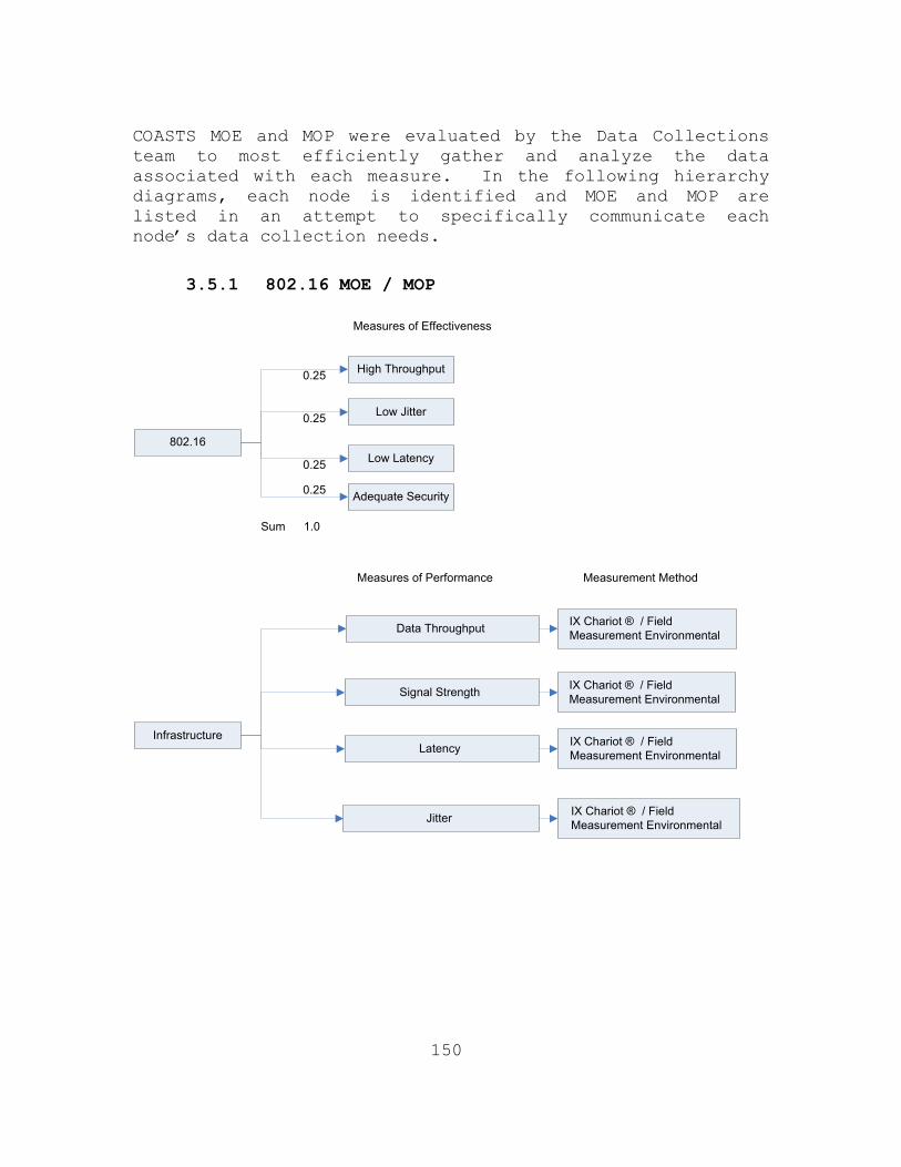
150
COASTS MOE and MOP were evaluated by the Data Collections team to most efficiently gather and analyze the data associated with each measure. In the following hierarchy diagrams, each node is identified and MOE and MOP are listed in an attempt to specifically communicate each node’s data collection needs.
3.5.1 802.16 MOE / MOP
High Throughput
Low Jitter
Low Latency802.16
0.25
0.25
0.25
1.0Sum
Adequate Security0.25
Measures of Effectiveness
Measures of Performance
Data Throughput
Signal Strength
InfrastructureLatency
Jitter
Measurement Method
IX Chariot ® / Field Measurement Environmental
IX Chariot ® / Field Measurement Environmental
IX Chariot ® / Field Measurement Environmental
IX Chariot ® / Field Measurement Environmental

151
3.5.2 802.11 MOP / MOE
Support marine and land platforms
100% seamlessCoverage for
designated area
Immediately availablefor purchase
802.11 Network
Mobile marine platforms to xx knots
Mobile and based platforms In dense
vegetation
No break in service when traversing AOR
0.3
0.25
0.1
1.0
0.5
0.5
1.0Sum
0.15
0.15
0.25
1.0Sum
100% COTS solution1.0
0.1
Support voice, video and data0.25 Real-time 0.251.0
Easily configurable0.1Max one day to
train personnel for setup1.00.1
Measures of Effectiveness
Measures of Performance
Throughput 54 Mbps; minimum acceptable 22Mbps
Bandwidth
802.11 NetworkMOPs Delay
Signal Quality
Measurement Method
IX Chariot ®
IX Chariot ®
IX Chariot ®
IX Chariot ®

152
3.5.3 Balloon MOE / MOP
Support marine and land platforms
100% seamlesscoverage
for designatedarea
Support voice, video and data
Easily configurable
Immediately available
for purchase
Balloon Nodes
Mobile marine platforms to xx knots
Mobile and based platforms
In dense vegetation
No break in service when traversing AOR
Real-time
Max one day to train personnel for setup
100% COTS solution
0.3
0.25
0.25
0.1
0.1
1.0
1.0
1.0
1.0
0.5
0.5
1.0Sum
0.15
0.15
0.25
0.25
0.1
0.1
1.0Sum
Assembly and deployment
Of each balloon node w/
In X minutes
Effective assembly and Installment of cameras
on payloads
Establish good throughput
Time w/ in mesh
Balloon Node MOP’s
Inflation of the balloonIn X minutes
Assembly of balloonPlatform and Winch
In X minutes
Support live video feeds To other nodes in802.11 network
With ground nodes
Assembly of balloon Payload and attachmentTo the balloon in X min
Launch and recoverBalloons from alt. in
X minutes
Support camera functions
(zoom, pan, tilt, focus)
With other air platform nodes
Establish good signal Strength w/ in mesh
No break in service when traversing AOR
Measures of Performance Measurement Method
Field / Timer
Field / Timer
IX Chariot ®
IX Chariot ®
Field / Timer
Field / Timer
Binary Observation
IX Chariot ®
IX Chariot ®
Measures of Effectiveness

153
3.5.4 C3 Track MOE -1
Absolute 3D Coordinates
Differential 3DCoordinates
Enabled GPS
Commandand
Control
Log GPS-based mobile user coordinates.
Log Inertial Navigation System-based mobile user coordinates.
Identify mission personnel and store coordinates
Determine mobile user location via reception and processing of GPS signals
via a GPS receiver
0.25
0.25
0.25
0.25
0.5
0.167
0.167
1.0Sum
0.04
0.04
1.0Sum
Display current mission personnel coordinates on 2D/3D Map User Interface
Display prior mission personnel (track/trajectory) 2D/3D Map User Interface. 0.167
0.167
0.04
0.04
Identify-save current track/trajectory
Display prior track/trajectory list0.167
0.167
0.04
0.04
0.0625
Identify mission personnel groupsand store coordinates0.25 0.0625
Display mission personnel list0.25 0.0625
Display mission personnel group list0.25 0.0625
Identify mission personnel groupsand store coordinates0.5
Denied GPS
Determine mobile user location via reception and processing of sensor
outputs via a mobile Inertial Navigation System where GPS signals cannot be
received or are inaccurate0.25
0.5
Automatically switch between GPS mode and Inertial Navigation System Mode0.5
0.125
0.125
0.125
0.125
Measures of Effectiveness

154
3.5.5 C3 Trak MOE - 2

155
3.5.6 C3Trak MOP - 1
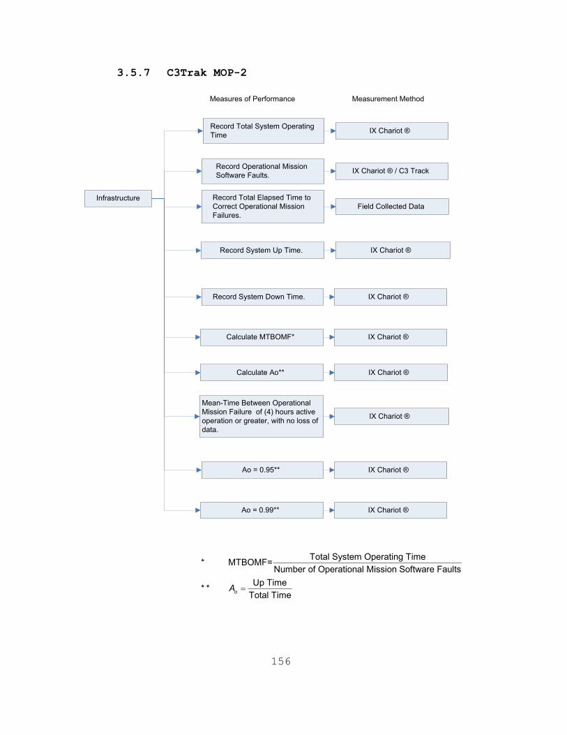
156
3.5.7 C3Trak MOP-2
Measures of Performance
Record Total System Operating Time
Record Operational Mission Software Faults.
Infrastructure Record Total Elapsed Time to Correct Operational Mission Failures.
Record System Up Time.
Measurement Method
IX Chariot ®
IX Chariot ® / C3 Track
Field Collected Data
IX Chariot ®
Record System Down Time.
Calculate MTBOMF*
Calculate Ao**
Mean-Time Between Operational Mission Failure of (4) hours active operation or greater, with no loss of data.
IX Chariot ®
IX Chariot ®
IX Chariot ®
IX Chariot ®
Ao = 0.95**
Ao = 0.99**
IX Chariot ®
IX Chariot ®
Total System Operating Time* MTBOMF=Number of Operational Mission Software Faults
Up Time* *Total TimeoA =

157
3.5.8 Cameras MOE / MOP
Multicast
Controllable
DeployableCameras
0.25
0.25
0.25
1.0Sum
Immediately Available to Purchase
0.125
Measures of Effectiveness
Measures of Performance
MPEG Format
Multicast Capability
Cameras
Control Pan / Tilt / Zoom
IR Illumination
Measurement Method
Field Measurement
IX Chariot ® / Binary
Field Measurement
Field Measurement / Binary
Easy to Configure0.125
20 Frames per second
Wireless Connectivity
IX Chariot ® / Field Measurement / Binary
IX Chariot ®

158
3.5.9 Sensors MOE
Detect objects in a marine environment0.5
0.125
Detect objects over land0.5
0.125
No lapses in coverage while traversing intended sensor grid1.0
0.05
Detect dismounted personnel0.333
0.1
Detect boat and automobile traffic0.333
0.1
Determine heading and velocity of object0.333
0.1
Max one day training for deployment personnel1.0
0.05
100% COTS1.0
0.05
Small logistics footprint0.20
0.06
Minimum battery life of 3 months0.20
0.06
Operate under adverse climactic conditions0.20
0.06
Operate in various environments0.20
0.06
Low time to set up and initialize0.20
0.06
Sensing Capabilities
Deployability
Sensors
0.30
0.30
1.0Sum 1.0Sum
Measures of Effectiveness
Operate in Maritime and Land Environments0.25
Seamless Coverage of Sensing Area0.05
Easily Configurable0.05
Immediately Available for purchase0.05

159
3.5.10 Sensors MOP
Measures of Performance
Number of False detections
Number of missed detections
Sensors
Range of detection in feet from sensor to target
Bandwidth used to communicate between nodes in Hz
Measurement Method
C3 Track / Field Measurement
C3 Track / Field Measurement
Field Measurement
Field Measurement
Data rate of transmission in bits per second
Time between sensing object and transmitting detection message in microseconds
Link Quality (Packets received/packets sent)
Latency
IX Chariot ®
Field Measurements
IX Chariot ®
IX Chariot ®
Time in minutes to deploy sensors
Ability to determine direction and speed of object it detects
Field Measurements
C3 Track

160
4.0 MANAGEMENT STRATEGY.
4.1 PARTICIPATING ORGANIZATIONS, ROLES, AND RESPONSIBILITIES.
4.1.1 COASTS Oversight Group.
The oversight committee will be chaired by the NPS Dean of Research. Membership includes the Director MDP-RG, COASTS Program Manager, the COASTS Operational Manager, the COASTS Air Marshall, and the COASTS Student Team and Network Leaders.
4.1.2 COASTS Program Manager (PM).
Lead element of the COASTS project; responsible for project execution, coordination between NPS, DoD, foreign partners, and commercial vendors; responsible for all fiduciary reports and contractual agreements. The COASTS 2006 PM is Mr. James Ehlert (Information Sciences Department faculty member).
4.1.3 COASTS Operational Manager (OM).
The OM is responsible for developing all demonstrations, plans, collection and dissemination of data, site surveys, MOE, MOP, NPS resource allocation, internal NPS coordination, and support to the PM. The OM plans, coordinates and directs all user activities related to the COASTS project. The OM will develop and provide the CONOPS, TTPs, operational mission scenarios, and the overall utility assessment. Additionally, the OM will coordinate administrative tasks for user participants, equipment and facilities supporting demonstration events. The COASTS 2006 OM is Mr. James Ehlert (Information Sciences Department faculty member).
4.1.4 COASTS Technical Manager (TM).
The TM is responsible for technical management including program management, engineering, and acquisition of technologies to integrate and demonstrate. The TM will provide technical support to the OM and manage all funding and technology development efforts related to the COASTS project. The TM has the overall responsibility for establishing criteria for technical performance

161
evaluations. The COASTS 2006 TM is Mr. James Ehlert (Information Sciences Department faculty member).
4.1.5 COASTS Air Marshall.
The COASTS Air Marshall is the authority on all aviation planning, management, and de-confliction. The Air Marshall will liaise with all contractors, Thailand aviation POCs, and all NPS aviation operators. All logistics requiring aviation assets will be managed and controlled by the Air Marshall. The COASTS 2006 Air Marshall is Mr. Ed Fisher (Information Sciences Department faculty member).
4.1.6 Participating Test Organizations.
The primary organization for assessment for the COASTS demonstration in Thailand is the Naval Postgraduate School. Other participating organizations are as follows: U.S. Pacific Command (USPACOM) Joint Inter-Agency Task Force West (JIATF-W) Joint Information Operations Center (JIOC) Royal Thai Armed Forces (RTARF) Thai Department of Research & Development Office (DRDO) 4.2 RISK ASSESSMENT, MANAGEMENT AND MITIGATION.
Overall risk is estimated to be low to medium for the COASTS May 2006 Thailand demonstration. Risks can be mitigated by either reducing or adding additional experiments as appropriate. The table below depicts the NPS developed risk matrix: Risk Area Rating Mitigation Approaches Technology Low
Medium - early/continuous coordination with partners - early prototyping - multiple data collection events - modeling and simulation - in-process reviews
Schedule - Technical
Low Medium
- schedule estimates based on technology provider agreements - schedule estimates COASTS 2005 lessons learned

162
Risk Area Rating Mitigation Approaches Schedule - Demos
Low Medium
- incremental demonstrations - identify/leverage existing events
Assessment Low - Individual researchers develop MoE and MoP for their components of the demonstration.
Funding Low - significant funding confirmed, additional sponsors contacted
Figure 17. Risk Matrix 4.3 DEVELOPMENT STRATEGY.
The appendices of this document will provide specific guidance on each particular area, element, and component under study during the COASTS demonstration.

163
5.0 TRAINING, LOGISTIC AND SAFETY.
5.1 TRAINING.
A primary goal of the COASTS project is to execute operational demonstrations in conjunction with U.S. and Thailand forces/resources. Accordingly, appropriate training materials will be developed for each demonstration and operator training will be conducted prior to each demonstration. Training will be performed by a combination of contractor and government personnel. There are also significant hands-on educational opportunities for NPS students, and it is expected that multiple NPS masters theses will be generated by participating US and foreign NPS students. 5.2 LOGISTICS.
Maintenance and logistics support will be conducted using a combination of contractor support and in-house NPS expertise and facilities. This includes the development and distribution of maintenance, training, and operating manuals, instructions, or materials. During the demonstrations reliability, availability, and maintainability information will be collected for later analysis and review.
5.2.1 COASTS Set-Up and Demonstration.
The COASTS team members will transit from Bangkok to Chiang Mai via civilian air transport. All COASTS equipment will be transported from the Bangkok International Airport to the Wing 41 RTAF air base via a RTAF-supplied C-130 or ground transport vehicle. The departure and return schedule are currently not determined but will be based upon operational and administrative requirements during each set-up or demonstration time period. NPS thesis students will handle the logistics, financial management of transportation, as well as necessary host nation support issues.
5.2.2 COASTS Equipment Shipping and Storage.
The NPS will provide JUSMAGTHAI (POC: Lt Col Mel Prell) and the American Embassy Bangkok (POC: LTC Mike Creed) with a list of equipment to be shipped in support of the March set-up and the May demonstration. JUSMAGTHAI

164
will help with the arrival of the equipment and facilitate processing through Thai Customs to minimize delays.
All COASTS equipment will be stored at either Wing 41 or at JUSMAGTHAI. The minimum requirements for either of these facilities will be controlled access (lock and key) to prevent the loss of equipment and air-conditioning to preserve the material condition of electronic devices. 5.3 SAFETY.
The potential exists for safety or environmental hazards associated with technologies being utilized. As needed, a safety analysis will be performed to identify potential safety hazards and risks and determine appropriate controls to preclude mishaps and reduce risks. This is especially true with regard to manned and unmanned flight operations. The OM will coordinate all safety efforts associated with demonstrations, with the assistance of the Air Marshall for flight operations (see next paragraph). Air-space management will be handed by the COASTS Air Marshall (Mr. Ed Fisher). Separation of the numerous aviation assets will ensure no collisions occur during field experiments in Point Sur and at the Mae Ngat Dam. An NPS student is designated as the COASTS 2006 Safety Officer, and will conduct all operations under the direction of U.S. Navy Safety Instructions. An Operational Risk Management (ORM) Matrix will be developed and adhered to during all operations. 6.0 MODIFICATIONS.
This CONOP is intended to be a living document. It will be updated as required to reflect changes to the COASTS project as it pertains to the Thailand demonstration. Most modifications will be at the discretion of the COASTS Oversight Group who will approve any substantive alterations to include changes in objectives, funding, schedule, and scope. Any changes which materially affect commitments made by Thailand will be approved by the affected organizations.

165
APPENDIX A-1. NETWORK TOPOLOGY
A. INTRODUCTION AND BACKGROUND
1. The goal of the COASTS network is to build and demonstrate the flexibility, mobility, durability, and scalability of COTS 802.11 a/b/g and 802.16 wireless networks deployed to rugged and varied terrain under adverse climatic conditions. These networks will be the infrastructure for transmitting state of the art sensor and ISR data providing improved tracking of littoral and ground movements, identifying which tracks are potential threats, prioritizing them for action, and providing engagement confirmation and battle damage assessment.
2. The COASTS network is designed to be robust, rapidly deployable, modular, and reconfigurable to meet all the needs of tactical, operational, theater, and strategic decision makers in coalition environments. COTS technologies, in particular open standard/open source technologies, provide these capabilities due to their ease of configuration, small form factor, technological proliferation, and low cost separate from the DoD acquisition bureaucracy.
B. 802.16 POINT TO POINT LONG HAUL COMMUNICATIONS SUITE
1. The 802.16 point-to-point links will provide long-haul connectivity between the scenario network at the Mae Ngat Dam and the IIFC in Chiang Mai, Thailand. The 802.16 technology was chosen for integration in the network due to its advantages over the alternative technologies for long-haul communications, namely 802.11, commercial SATCOM (COMSATCOM), and terrestrial (802.3) infrastructure. Specific advantages of 802.16 include:
a. Greater range than 802.11 technologies
b. Higher data throughput rates than COMSATCOM
c. No terrestrial infrastructure required
d. Low cost alternative to COMSATCOM and terrestrial communications
2. Product Information
a. Redline Communications Pre-IEEE 802.16 Compliant Products:

166
i. AN-50e
- Point to point suite consisting of two base stations, two radio transceiver, and two parabolic flat panel antenna of various sizes.
- Provides high data throughput (up to 54 Mbps) rates with very low latency or jitter at ranges of up to 30 KM.
C. 802.16 POINT TO MULTI-POINT MOBILE COMMUNICATIONS
SUITE
1. The 802.16 point to multi-point communications suite will provide mobile connectivity to maritime assets on the Mae Ngat Reservoir. The 802.16 technology was chosen for integration in the network due its superiority over other wireless technologies for mobile and multipoint wireless networking. Specific advantages include:
a. Client stations associate with only one master station. Clients do not need to constantly re-associate with “in range” access points as is the case with 802.11 coverage.
b. 802.16 communication protocol allows for high relative velocities between master and client stations; 802.11 does not have this capability.
c. Greater range than 802.11 coverage.
2. Product Information
a. Redline Communications Pre-IEEE 802.16 Compliant Products
i. ST-58E
- Man portable client station 802.16 point to multi-point networks.
- Provides high data throughput rates (up to 54 Mbps) to mobile clients at speeds up to 150 Kts.
.ii. Point-to-Multipoint configured AN-50E
- Same technology as the PtP AN-50. It includes a special firmware installation that enables routing to multiple slave stations.

167
D. 802.11 WIRELESS MESHED NETWORKS
1. The Wi-Fi network provides connectivity for mobile clients both on the ground and in the air. Wrapped in a lighter package than other technologies, 802.11 provides the throughput required to utilize various commercial technologies such as VoIP, real-time video, as well as sensor to shooter and intelligence collection data.
2. The 802.11 mesh network technology was chosen for its advantages over alternate methods of wireless local area networking technology such as conventional 802.11, 802.16, and analog radios. In addition, the proliferation of 802.11 enabled clients makes the use of an 802.11 network almost mandatory. Specific advantages of 802.11 mesh networks include the following:
a. It is self-forming and self-healing unlike conventional 802.11.
b. It has higher throughput, lighter pack weight and lower power consumption than analog radios
c. It has a smaller form factor than 802.16.
3. Product Information
a. Mesh Dynamics MD-300 Series
b. Specifications • 2.4GHz Structured MeshTM backhaul • Self-healing and self-forming • Session-persistent roaming • Integrated 802.11 b/g access • AES-CCMP encrypted backhaul • WPA (Personal and Enterprise) security • Multiple-SSIDs with 802.1q VLAN support • Independent Security profile per SSID • Remote Management and Monitoring • Power over Ethernet • NEMA rated outdoor enclosure
E. COMMERCIAL SATELLITE COMMUNICATIONS
802.16 point-to-point and point-to-multipoint will be employed to provide long-haul data transmission link from the mesh-network to the IIFC. Satellite transmission will provide connectivity between regional fusion centers located at Bangkok, Thailand and California, USA.

168
Commercial satellite connectivity will serve as an internet gateway to the World-Wide Web.
F. SHARED SITUATIONAL AWARENESS APPLICATION
1. C3Trak (see Figure 18 next page) serves as a mobile, distributed and networked personnel management system that delivers situational awareness capabilities in support of military and law enforcement operations. C3Trak aggregates, processes and displays navigational, environmental, and asset management data, in near real-time, to facilitate C2 decision-making, and the generation and publishing of plans and orders. C3Trak is comprised of three tiers of applications connected through a high speed wireless local area mesh network, and a high speed wireless long-haul wide area network backbone. Military/law enforcement utility of C3Trak involves surveillance and tracking and search and rescue mission areas, but C3Trak can be applied to a number of different mission areas where mobile ad-hoc networking is required. local commander the situational awareness needed to be able to act and react decisively.
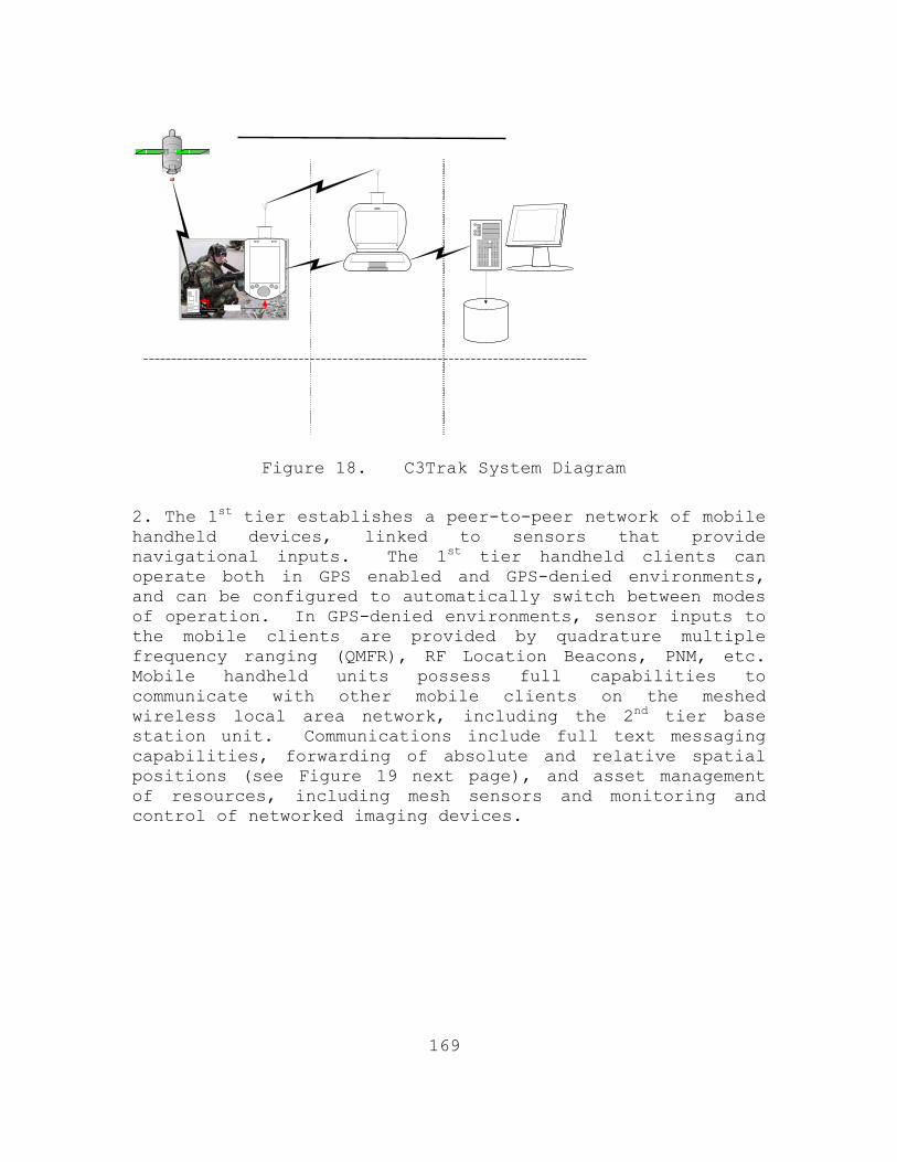
169
Figure 18. C3Trak System Diagram
2. The 1st tier establishes a peer-to-peer network of mobile handheld devices, linked to sensors that provide navigational inputs. The 1st tier handheld clients can operate both in GPS enabled and GPS-denied environments, and can be configured to automatically switch between modes of operation. In GPS-denied environments, sensor inputs to the mobile clients are provided by quadrature multiple frequency ranging (QMFR), RF Location Beacons, PNM, etc. Mobile handheld units possess full capabilities to communicate with other mobile clients on the meshed wireless local area network, including the 2nd tier base station unit. Communications include full text messaging capabilities, forwarding of absolute and relative spatial positions (see Figure 19 next page), and asset management of resources, including mesh sensors and monitoring and control of networked imaging devices.

170
Figure 19. Position sensor integration
3. The 2nd tier base station unit serves as the primary command and control node in the local area network. It provides a near real time common operational picture as it correlates and fuses data from multiple sensors and intelligence sources to provide the local commander the situational awareness needed to be able to act and react decisively. The base station unit acts as the intermediary between the mobile clients and the data warehousing and processing 3rd tier relational database management system. Similar to the handheld mobile clients, the base station unit possesses an extensive suite of integrated automation, messaging, and collaborative applications. However, the base station unit incorporates additional aggregation and processing applications to facilitate the local area commander with mission planning and execution. The 2nd tier feeds aggregated data, by way of a high speed wireless long-haul communications link, to the 3rd tier relational database.
4. The 3rd tier applications incorporate the force monitoring applications required by the regional commanders to effectively assess military operations. It is comprised

171
of a series of redundant relational database and web-host servers, designed to accommodate and process the large volumes of data sent from the local area meshed network
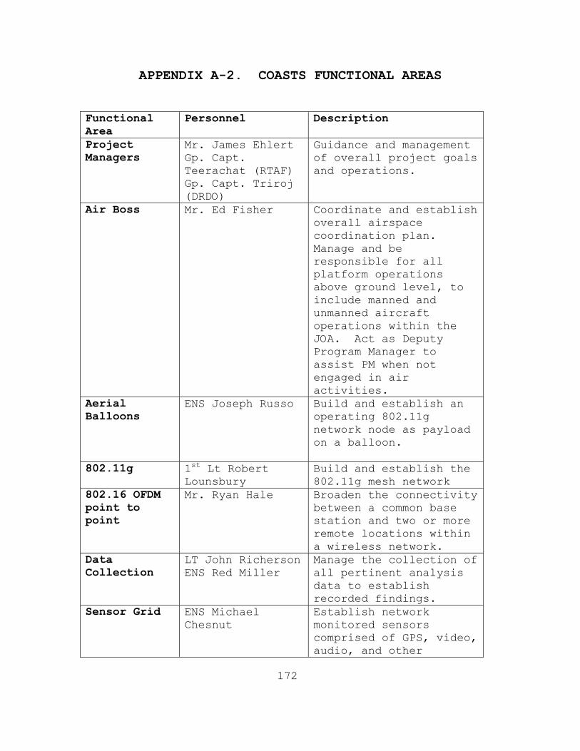
172
APPENDIX A-2. COASTS FUNCTIONAL AREAS
Functional Area
Personnel Description
Project Managers
Mr. James Ehlert Gp. Capt. Teerachat (RTAF) Gp. Capt. Triroj (DRDO)
Guidance and management of overall project goals and operations.
Air Boss Mr. Ed Fisher Coordinate and establish overall airspace coordination plan. Manage and be responsible for all platform operations above ground level, to include manned and unmanned aircraft operations within the JOA. Act as Deputy Program Manager to assist PM when not engaged in air activities.
Aerial Balloons
ENS Joseph Russo
Build and establish an operating 802.11g network node as payload on a balloon.
802.11g 1st Lt Robert Lounsbury
Build and establish the 802.11g mesh network
802.16 OFDM point to point
Mr. Ryan Hale Broaden the connectivity between a common base station and two or more remote locations within a wireless network.
Data Collection
LT John Richerson ENS Red Miller
Manage the collection of all pertinent analysis data to establish recorded findings.
Sensor Grid
ENS Michael Chesnut
Establish network monitored sensors comprised of GPS, video, audio, and other

173
Functional Area
Personnel Description
sensors. Video ENS Michael
Chesnut Establish and manage all video collection assets on the network.
Network Topology
LT Jonathon Powers Mr. Ryan Hale
Define the layer 1 (physical layer) requirements and components for the overall network operations.
Situational Awareness
Mr. Rich Guarino
Interface with COTS providers to establish a situational awareness solution for the COASTS program.
Evaluation Mr. Robert Sandoval
Monitor and provide networking metrics for the establishment for the COASTS network.
Vulnerability Assessment
LT Jonathon Powers Mr. Ryan Hale
Define, establish, and provide solutions for the critical network vulnerabilities.
Weather LT John Richerson Monitor and provide meteorological information for further correlation to network operating characteristics.
COC ENS Stephen Schall
Build and operate a command center in which to coordinate all network operations.
SATCOM MAJ Joel Pourdrier
Build and establish a SATCOM link to show portable link capability.
Strategic Node
LCDR Kris Runaas LCDR Ed Gawaran
Manage the Strategic Data Link at the receive node at the Alameda, CA USCG Data Fusion Center.
UAV (fixed ENS Michael Hsu Manage and control the

174
Functional Area
Personnel Description
wing) Cyberdefense micro-UAV: Cyberbug. Establish Network link to the UAV.
UAV (rotary wing)
ENS Scott Diamond Manage and control the Roto-motion micro-UAV. Establish Network link to the UAV.
UAV (kite) Mr. Ryan Hale Manage and control the helia-kite network extender.
Deny GPS ENS Phong Le Manage and establish the Deny GPS technology to establish node testing.
UAV (MMLAV) Capt Josh Kiihne Capt Drew Bledsoe
Build, manage, and establish the transformable micro-UAV. To include the network connection to the UAV.
802.16 OFDM point to multi-point maritime link
LT Rob Hochstedler
Build FLAK in order to establish an over-water 802.16 maritime security link.
802.11 Backhaul
ENS Stephen Crawford
Test and support the 802.11 deployment.

175
APPENDIX A-3. NPS THESIS RESEARCH IN SUPPORT OF COASTS 2006
LT Hochstedler Wireless Network Topologies ISO countering Asymmetric Threats in the Maritime Environment
LT Powers Data Compression Applications in deployed Wireless Networking
ENS Chesnut Applications of Integrated Sensors for Tactical operations
LT Richerson Optimization studies for the Usage of Micro-UAVs in a Tactical Environment
ENS Le Deny GPS in tactical wireless environments LCDR Runaas LCDR Gawaran
IT Costs of deploying Hastily Formed wireless networks into tactical theatres of operation
ENS Diamond Use of wireless networks ISO fire-control data passage to Strike Operations
ENS Russo Deployment of Lighter than air vehicles in tactical wireless network deployments
ENS Hsu Deployment of micro-UAVs for support of ISR in tactical environments
1st Lt Lounsbury
Deployment of 802.11g wireless networks ISO tactical operations
MAJ Pourdrier Analysis of UAV-received intelligence in combat operations
Capt Kiihne Capt Bledsoe
Design and analysis of a transformable mini-UAV
LCDR Keith Applegate
Analysis of Logistical requirements for deploying wireless networks
MAJ Quimby Maj Potraz
Wireless Network Security in Tactical Network Deployments
ENS Crawford Study of 802.11 backhaul configurations for Tactical Deployments
ENS Schall Code applications in wireless sensor deployments
ENS Miller Data Collection in wireless network deployments

176
Figure 20. COASTS 2006 Personnel Design Matrix
Program Manager
Faculty Advisor
Student Lead
Network Lead
Data Collect ENS
Miller
Aviation
Sensors ENS Chesn
Data Collect
LT Richerso
COC ENS Scha
802.11g
802.16
Balloon ENS Russo
UAV ENS
Cameras ENS
Chesnut
SAT-COM MAJ
Poudrier
UAV ROTO ENS Diamo
JIATF-W LTC Creed
Deny-GPS ENS
JUSMAGTHAI LTC Prell
Software Guarino
Mobile COC John
Pierson
UAV (Shift) Capt Kiihne
Faculty Advisor
Financial LCDR Runaas LCDR Gawaran
Logistics LCDR
Biometrics
Network Security Quimby Portraz

177
Figure 21. COASTS 2006 Personnel Deployment Matrix
Program Manager
Student Lead Hochstedler
Network Lead Powers
IIFC Ehlert
MIFC COC I Runaas
MIFC COC II Gawara
n
COC OP Poudrier /
Sensors
Aviation LD SAT-
COM JP
UAV OP Hsu
BOAT I Apples
BOAT II Hochstedle
Mobile COC-OP Schall
ROTO-OP Diamond
Data Coll UAV
(Shift)
Bledso
Data Coll.
ITT/Mesh
Deny GPS
Balloon I Russo Mobile
COC-OP II
Crawfor

178
APPENDIX A-4. DATA COLLECTIONS
A. INTRODUCTION AND BACKGROUND
1. Validation of hypotheses using collected data is an essential step in the process of research. Be it test and evaluation, proof of concept, or theoretical modeling, the collection and analysis of data provide accepted mathematically rigorous means by which conclusions are drawn. In the context of COASTS, data collection and analysis are a means to empower decision makers to draw conclusions based on data collected in the field for each phase of COASTS 2006.
B. METHODOLOGY
1. Data Collection Points
a. Environmental Data
Based on past observation of network performance in Thailand, it is theorized that network performance is significantly affected by temperature. To validate this hypothesis and potentially model the affects of temperature on network performance meteorological data will be collected in each phase of the COASTS project. For the context of COASTS 2006, distance measurements and locations are also considered environmental data.
b. Benchmarking Data
MOE and MOP inputs primarily drive the need for benchmarking by identifying specific metrics of concern and providing thresholds of acceptable performance. Specific metrics require a trend of performance across a specified range that can only be evaluated against preliminary, or benchmark data. Still other metrics require specific performance thresholds at all levels of effective use.
Data collected before the Thailand phase of operations provides a pool of data collected in known conditions to compare to data collected in the operational phase. Also, initial conclusions and potential areas of interest may be generated through the analysis of this initial data. The data also provides a means to analyze the performance of sensor systems and network hardware against the claims of the manufacturers.

179
Examples of benchmarking are the observed rate of detection at given distances for a specific sensor or the observed signal strength generated from a specific antenna at given distances.
c. Network Data
Performance of computing networks is potentially affected by a wide and varied array of inputs and atmospheric conditions. Signal strength, latency, throughput, packet loss, and jitter are just a few of the performance measures associated with network performance. Each of these and additional measures will be collected throughout the project using a commercial application that collects and stores data network specific data. A time stamp is associated with each data point to match network data with data collected apart from the network.
d. User Data
Subjective data such as ease of use and usability of displayed information will be developed as categorical data. This will enable regressive techniques to be used from which the team can draw more useful conclusions.
e. Data Collection Operations
To the maximum extent possible, data collection will be conducted in a manner that minimizes error. When possible gauge error will be estimated from manufacturer specification and input into the statistical model. Data collection methods will be utilized that minimize the impact on the observed values.
f. Data Preparation / Model Formulation
Once data has been collected, a permanent copy of all raw data will be kept in a central location by the Data Collection node leader. Data normalization and manipulation will only be carried out with copies of the raw data collected.
Statistical models will, to the maximum extent possible, minimize variability while maintaining accuracy and tractability. Construction of statistical models will be documented in such a manner as to assure reconstruction of the model solely from the documentation.

180
g. Analysis and Conclusions
Only after statistical models have been constructed and validated in accordance with paragraph f. above will any inference from analysis be undertaken.

181
APPENDIX A-5. MINI-UAVS
A. INTRODUCTION AND BACKGROUND
Mini-UAVs will be used in the COASTS scenario to provide tactically persistent surveillance/reconnaissance. In the 2006 Thailand field experiment, presence of potential bad actors will be noted by sensor-“triggers”, and mini-UAVs will be launched to gain additional information on these bad actors and pass the information to local-tactical, regional-operational, and strategic C2 centers for continued consideration.
B. CYBERDEFENSE CYBERBUG MINI-UAV
The CyberBug is a small, lightweight, scaleable, low-cost mini-UAV. One man may unpack, assemble, and launch the CyberBug in under one minute. It is hand-launched and capable of utilizing an auto-land system. It may be programmed for autonomous operation with manual override available. It is normally equipped with a stabilized gimbaled low light high resolution camera, and an IR camera

182
payload is available. It is electrically powered, and has about 45 minutes endurance.
• Length 25-56 inches • Wing span 30 inches to 60 inches • Weight ~ 2.6 pounds scalable to 5 pounds • 45 minutes to 3.5 hours approximate flight time • 5-20 MPH • Autopilot / GPS navigation • Hand held viewer and joy-stick • Small 12x camera w/Optional cameras for day and
IR(Indigo) • 9 -18 Volt battery • Carrying case (small unit) • EO/IR payload is scalable up to several pounds • Includes short range data link (long range is option)
C. ROTOMOTION SR-100 MINI-UAV

183
The Rotomotion SR-100 is a relatively small vertical take-off and landing UAV. It may be programmed for autonomous operation or can be flown manually. It has an auto-land and auto-takeoff capability. It may be equipped with either a day camera or an IR camera, and utilized a low-jitter capability to stabilize the video feed. It may be gasoline, diesel, or electrically powered. If equipped with the electrical motor (COASTS preference for low-observable operations), it has about 60 minutes endurance.
• 802.11-based Telemetry System • Length:2250 mm, 89” • Main Rotor (M/R) Dia.:1900 mm, 75” • Dry Weight:16 kg, 35lbs. • Fuel Cap:2 liter, 67 oz. ,(alcohol,diesel,50:1, 2cycle
gasoline)up to 14 liter, 470 oz., tanks available • Engine :2-Stroke gasoline, alcohol, diesel conversion,
or electric • Generator (optional):150W, 12V power bus with battery
backup • Climb rate:122 mpm, 400fpm (AFCS regulated) • Speed:10 mps, 65 fps (AFCS regulated) • Endurance:30 min to 2 hours (depending on fuel tank
configuration) • Max Payload: up to 7 kg, 20 lbs (depending on options,
altitude, fuel load)

184
APPENDIX A-6. COASTS 2006 STORYLINE
The arrival of a longboat suspected of involvement in drug and arms smuggling operations will be detected by various unattended sensor suites deployed at a tactical waterborne choke-point(s). When triggered by the motion of the longboat, the sensors will send an automatic system alert through the C3Trak SSA application. This system alert will be observed by all the tactical forces connected to the network (refer to Figure 2), by the local C2 center (the IIFC in Chiang Mai), by the remote C2 center in Bangkok (RTAF HQ) and finally by the strategic C2 center in Alameda, CA (at the U.S. Coast Guard Maritime Intelligence Fusion Center (MIFC)). The coalition small boat unit will also receive the alert via the 802.16 OFDM mesh network. Coalition small boats, camouflaged as local river merchants, will track the longboat, passing intelligence via Voice-over-IP (VoIP) communications and imagery back via mounted IP cameras over a wireless link. The system alert will enable coalition operators to track the movement of the longboat through various sensors deployed along the waterway. At a pre-determined trigger point, the tactical C2 center will order the launch of the mini-UAVs and the full-sized UAV to establish tactical persistent surveillance. The UAVs will pass video (electro-optical and infrared) through a wireless network established by four tethered aerial balloons, operating at altitudes up to 3500 feet, and each equipped with a wireless access point, and one non-tethered unmanned lighter-than-air vehicle (LAV) operating at altitudes of up to 10,000 feet. The data obtained from the UAVs will be collected, fused, and disseminated by the C3Trak application to the on-scene commanders in the Mobile Command Platform (MCP). When the longboat arrives at a “drop-point” (near the end of the reservoir, close by the Mae Ngat Dam Boat Shop) the drug and explosive shipment will be transferred into the cargo bed of two awaiting trucks and an unidentified bad actor (man) is given a CD (contents include the details of the smuggling operation to include financial ties with terrorist organizations). This entire process is being remotely monitored (UAVs and balloons) and displayed at the local, regional, and strategic C2 centers. After the

185
transfer is complete, the longboat departs along the reverse route. A bad actor convoy (two trucks) is tracked as it moves along the road atop the Mae Ngat Dam while the individual bad actor will leave on foot on a northward path. The scenario will then split into two parts to research, test, and display the versatility and multi-tasking potential of the COASTS network. One part will entail the bad actor being tracked on foot by a Royal Thai Army and Police squad. The bad actor will cross land-based sensor suites, again initiating a C3Trak system-wide alert. The IIFC will order the interdiction squad (equipped with a wearable computing device which can send/receive all network data, and biometric and explosive residue collection capabilities) to coordinate the apprehension of the suspected bad actor. The second part of the scenario will entail the convoy being tracked by the network sensors simultaneously. The vehicle carrying the larger portion of the drugs will also cross a Guardian sensor grid, deployed alongside the road, sending another C3Trak system-wide alert. At this point, orders will be passed from the strategic command and control center (MIFC), via the operational node in Bangkok (RTAF HQ), to capture all monitored units: longboat, trucks, and bad actor. The bad actor will be captured without incident, but both the longboat and trucks are armed and put up heavy resistance against capture. Both the coalition small boat team and the vehicle interception team pass SITREPS via the COASTS network requesting tactical air support (L-39 jets). After apprehension of the bad actor is affected, biometric data will be gathered and passed to the MIFC for identity verification. Once positive confirmation is received that the captive is the high value target in question, the coalition ground forces holding the bad actor will pass initial intelligence from the CD (captured with the bad actor’s personal effects) and initial custody status via C3Trak to all network users as well as the IIFC and MIFC. The COASTS Watch Officer (CWO) at the IIFC will request an air strike against the convoy from RTAF HQ. As part of this request the CWO will pass GPS positions and other

186
targeting information. The RTAF HQ directs two L-39s from Wing 41 to conduct the air-to-surface strike. Concurrently, coalition maritime interdiction teams will apprehend the long boat. After apprehension of the bad actors, biometric data will be gathered and passed to the MIFC for identity verification. Once directed to maintain custody of the bad actors, the coalition maritime interdiction team will pass mission status via C3Trak to all network users as well as the IIFC and MIFC. The L-39’s loiter pending resolution of the maritime interdiction. The scenario will finish after the maritime interdiction is completed and the L-39’s have departed the JOA.

187
APPENDIX A-7. DISTRIBUTION LIST
1. Mr. James F. Ehlert Director, Maritime Domain Protection Research Group (MDP-RG) Naval Postgraduate School Monterey, California
2. Colonel Thomas Lee Williams
Deputy Science Advisor U.S. Pacific Command (USPACOM)
Camp Smith, Hawaii 3. Mr. Russ Holland, Chief of Staff Joint Inter-Agency Task Force West (JIATF-W)
Camp Smith, Hawaii 4. Mr. Kurt Badescher US Special Operations Command (USSOCOM), Tampa, Florida 5. Mr. J. Christopher Griffin,
Westwood Computer Corporation 6. Mr. Ralph L. Boyce, US Ambassador of Thailand US Department of State (DoS)
Bangkok 10330 Thailand 7. Lt Col Mel Prell, USAF Joint US Military Advisory Group Thailand (JUSMAGTHAI)
Bangkok 10120 Thailand 8. Lieutenant General Krita Kritakara Deputy Secretary Thailand National Security Council (NSC)
Bangkok, Thailand 9. Lieutenant General Apichart
Director-General, Defence Research & Development Office (DRDO) Parkred, Nonthaburi

188
10. Group Captain Dr. Triroj Virojtriratana DRDO COASTS Project Manager Parkred, Nonthaburi
11. Group Captain Wanchai Tosuwan
Director, Research & Development Promotion Division Parkred, Nonthaburi
12. Group Captain Teerachat Krajomkeaw Directorate of Operations Royal Thailand Air Force (RTAF) Headquarters
Bangkok, Thailand 13. Mr. John Laine Senior Contractor, JIATF-West Interagency Intelligence Fusion Center (IIFC)
Chang Mai, Thailand 14. Mr. Craig Shultz Lawrence Livermore Laboratories (LLNL) 7000 East Avenue
Livermore, California 15. Mr. Robert Sandoval Joint Intelligence Operations Command (JIOC)
San Antonio, Texas 16. John Taylor President, Mercury Data Systems
Greensboro, North Carolina 17. Captain Phil Erdie, USMC
U.S. Marine Corp Systems Command (MARCORSYSCOM) Quantico, Virginia
18. Mr. Thomas Latta
C4ISR & IO PM Space and Naval Warfare Systems Command 2721 C4ISR SE&IM Division, SSC-SD 80 Dept, 86 CND/IO OT&E Branch, COMOPTEVFOR DOT&E IA&I/IO OT&E Assessment Programs
19. RADM Nimmick, USCG
Maritime Intelligence Fusion Center (MIFC) Alameda, California

189
20. Mr. Jim Alman President, CyberDefense UAV Systems
St Petersburg, Florida 21. Mr. Dennis B. D'Annunzio
COO, Rotomotion, LLC Charleston, South Carolina
22. Mr. Curtis White
Commander’s Representative AFRL/XPW – AFFB/CCT USAF Force Protection Battle Lab Lackland AFB, Texas
23. Mr. Archie Newell
Cisco Systems 24. Mr. Mike Rathwell Identix Corporation
One Exchange Place Jersey City, New Jersey
25. Dr. Leonard Ferrari
Dean of Research Naval Postgraduate School
Monterey, California 26. Dr. Pat Sankar
NPS Distinguished Fellow Naval Postgraduate School
Monterey, California 27. Dr. Gurminder Singh
Director of the Center for the Study of Mobile Devices and Communications Naval Postgraduate School Monterey, California
28. Dr. Carlos Borges Mathematics Department Naval Postgraduate School Monterey, California

190
29. Dr. Frank Shoup Director of Research, Meyers Institute, GSEAS Naval Postgraduate School Monterey, California
30. Dr. Dan Boger Chairman, Graduate School of Information Sciences Naval Postgraduate School Monterey, California

191
APPENDIX B. TETHERED BALLOON SET-UP
Table of Contents I. Balloon Platform Assembly
II. Balloon Inflation and Deflation
III. Winch Set-up and Operation
I. BALLOON PLATFORM ASSEMBLY
A. Equipment • 2’ x 4’ x ½” piece of plywood (this serves
as the centerpiece of the platform)
• Seven (7) 2” x 4” x 4’ wood beams
• Twenty (20) 2-1/2” Wood Screws
• One (1) 3/4” Pad Eye Screw
B. Assembly
• Take three 2’x4’s and lay them parallel to each other. The two outside 2’x4’s should be 4’ apart and the middle board should be placed evenly between the two outer boards.
• Place the ½” plywood in the center of the three base boards. Ensure that that the plywood center piece is 24” wide and 48” long. Center the plywood on the base boards so that approximately 12” (from each end of the center piece) of the base boards remain exposed.
• Use the wood screws to secure the plywood to the three base boards.
• Take two of the remaining 2”x4”x4’ wood boards and place them in the same direction as the center board across the exposed portions of the base boards. Place them opposite of each other, perpendicular and aligned at the ends of the baseboards.

192
• Fasten these boards to the base boards with wood screws.
• Take the remaining two 2”x4”x4’ wood boards and place them parallel to the center boards and the end boards, ensuring that they are touching the center board.
• Attach these boards to the base boards with wood screws.
• The Pad-eye screw should be placed on the outside of the platform and centered on the plywood piece.
II. THE BALLOON
The balloon purchased by the COASTS 2006 team was a
10-foot, sphere-shaped, helium balloon from the commercial
company BlimpWorks.
Figure 1 COASTS 2006 Balloon
A. Balloon Station Set-up
• Layout a 10’x20’ tarp on the ground
• Lay the wooden platform on the ground on the middle edge of one side of the tarp

193
• Place the winch on the platform and screw it into the platform
• Set up three anchor lines
• One anchored to the pad-eye screw on the platform
• One anchored approximately fifty feet away from the platform on each end (use trees, guard rails, fences, etc.)
B. Balloon Inflation
• Stand helium tank straight up and remove protective lid.
• Screw the nozzle of the inflation hose into the valve of the helium tank.
• Unfold the balloon and lay it flat on the ground
Figure 2 Balloon Laid Out Flat Before Inflation
• Attach the winch line and anchor lines to the metal ring on the balloon with a carabineer.
• Take a 10-foot piece of thick nylon rope and attach it to the loop on the top of the balloon (the side opposite of where the metal ring is) with a carabineer.

194
Figure 3 Thick Nylon Rope Attached to Top of Balloon
• Open the large opening on the bottom of the balloon by removing the plug.
• Insert about two feet of the inflation hose into the opening
Figure 4 Inserting Inflation Hose into Balloon

195
• Open the helium tank slowly and start inflating the balloon (Note: Inflating the balloon too quickly may cause damage to the balloon).
• As the balloon lifts off the ground make sure that someone is holding onto the area where the inflation hose is inserted into the balloon (Note: Do not pull the balloon down when holding it here because it will rip the seams of the balloon)
• Be sure that the balloon is not filled completely to the point that it is very firm.
• When the balloon is done inflating, remove the inflation hose and close the inflation valve at the bottom
C. Balloon Deflation
• Open the valve on the bottom of the balloon
• Take the piece of nylon rope that is attached to the top of the balloon and tie it to the pad-eye screw on the platform
• Keep the winch line attached to the metal ring and let enough of the winch line out so that the open valve is pointing directly up

196
Figure 5 Balloon Being Deflated
• As the balloon sinks down to the ground, begin laying it flat across the tarp
Figure 6 Lying Balloon on Tarp During Deflation
• Once the balloon in empty and laid flat across the tarp, fold in each side of the balloon towards the center
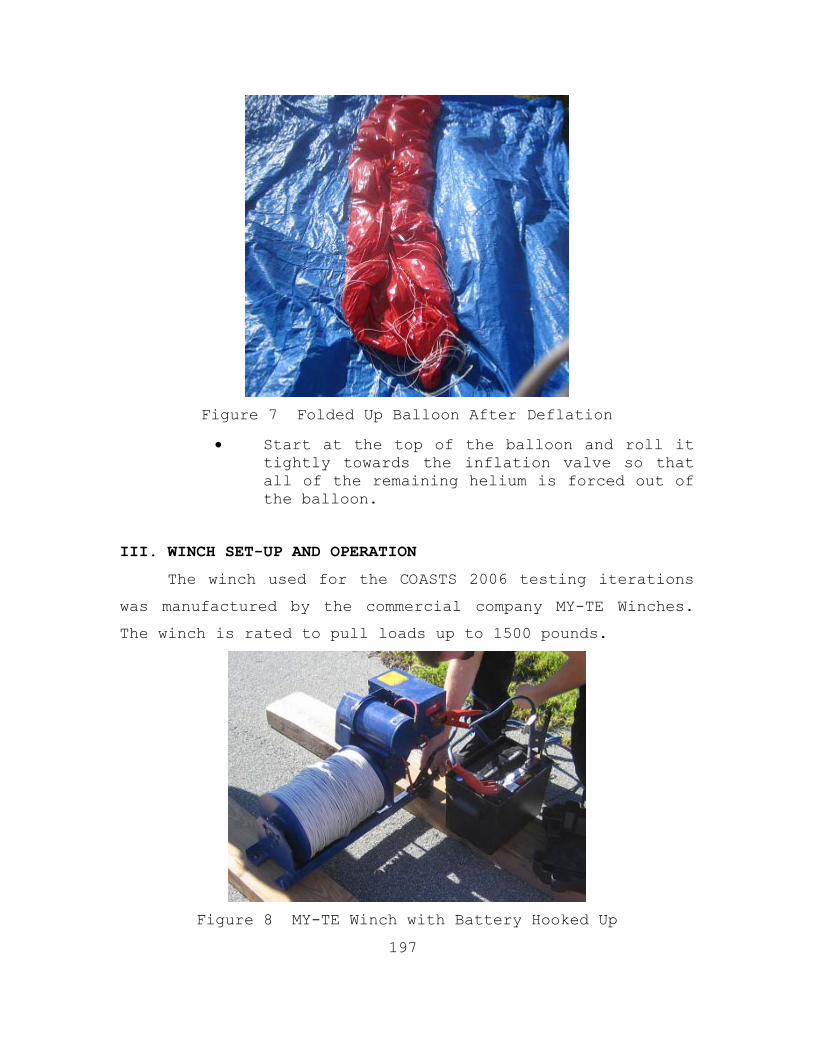
197
Figure 7 Folded Up Balloon After Deflation
• Start at the top of the balloon and roll it tightly towards the inflation valve so that all of the remaining helium is forced out of the balloon.
III. WINCH SET-UP AND OPERATION
The winch used for the COASTS 2006 testing iterations
was manufactured by the commercial company MY-TE Winches.
The winch is rated to pull loads up to 1500 pounds.
Figure 8 MY-TE Winch with Battery Hooked Up

198
The equipment needed to operate the winch includes:
• One 12 VDC Car Battery
• One set of car battery jumper cables
• 1000lb Test Spectra Line
A. Winch Operation
• The balloon comes equipped with a switch that allows the user to reel the line in or let the line out
• The manual clutch is the locking mechanism for the winch.
1. Deploying the Balloon
• To deploy the balloon, connect the battery cable to the battery and the winch and operate the switch in the desired direction.
• To deploy the balloon manually, the manual brake must be released. To release the brake, the operator slowly pulls the brake handle in a downward motion (toward the operator) to release the safety latch, then slide the operator away from the drum.
2. Retrieving the Balloon
• Press the “IN” button on the switch panel
• Using a carabineer, guide the line onto the spool so it will wind evenly onto the spool.
• Once the balloon is at the desired height, discontinue pressing the “IN” button.
• Secure the balloon with the anchor lines
199
LIST OF REFERENCES
1. Alberts, David S., John J. Garstka, and Frederick P. Stein. 1999. Network Centric Warfare: Developing and Leveraging Information Superiority. 2nd ed. Washington, D.C.: CCRP. 2. Alicherry, Mansoor and Randeep Bhatia. 2005. Joint Channel Assignment and Routing for Throughput Optimization in Multi-radio Wireless Mesh Networks. Proceedings of the 11th Annual International Conference on Mobile Computing and Networking, (August 28), http://delivery.acm.org.libproxy.nps. Navy.mil/10.1145/1090000/1080836/p58alicherry.pdf? Key1=1080836&key2=6715945411&coll=ACM&dl=ACM&CFID= 74126661&CFTOKEN=85644296 (accessed April 7, 2006). 3. Benbow, Robert, Fred Ensminger, Scott Savitz, Major Dan Stimpson, and Peter Swartz. 2006. Renewal of Navy’s Riverine Capability: A Preliminary Examination of Past, Current, and Future Capabilities. Alexandria, Virginia: CNA. 4. Coalition Operating Area Surveillance and Targeting System (COASTS) Thailand Field Experiment (May 2005) After Action Report. Naval Postgraduate School, Monterey, California. Duplicated. 5. Coalition Operating Area Surveillance and Targeting System (COASTS) Thailand Field Experiment (May 2006) Concept of Operations. Naval Postgraduate School, Monterey, California. Duplicated. 6. DeMartino, Kevin. 2003. An Architecture for a Seamless Mesh Network. Fourth International Workshop on Design of Reliable Communications Networks, 2003, (October 19), http://ieeexplore.ieee.org.libproxy. Nps.navy.mil/ie15/8992/285334/01275384.pdf?tp=&arnum Ber=1275384&isnumber=28534 (accessed April 7, 2006).

200
7. Jun, Jangeun and Mihail L. Sichitiu. 2003. The Nominal Capacity of Wireless Meshed Networks. IEEE Wireless Communications 10, no. 5 (October), http://ieeexplor e.ieee.org.libproxy.nps.navy.mil/ie15/7742/27826/012 41089.pdf?tp=arnumber=1241089&isnumber=27826 (accessed April 7, 2006). 8. Lee, C. 2005. Aerial Command and Control Utilizing Wireless meshed Networks in Support of Joint Tactical Coalition Operations. Master’s Thesis, Naval Postgraduate School, Monterey, California. 9. Lounsbury, R. 2005. Coalition Operating Area Surveillance and Targeting System 2006 802.11 Aerial Payload Solution. Directed Study, Naval Postgraduate School, Monterey, California. 10. Lounsbury, R. 2006. Coalition Operating Area Surveillance and Targeting System 2006 802.11 Optimum Antenna Configuration. Directed Study, Naval Postgraduate School, Monterey, California. 11. Mills, Eric. “An Integrated Battle Space: Riverine Warfare Conference Final Wrap-Up,” U.S. Naval Institute, April 10, 2006. 12. Naghian, Siamak. 2004. Mesh vs. Point-to-Multipoint Topology: A Coverage and Spectrum Efficiency Comparison. 15th IEEE International Symposium on Personal, Indoor, and Mobile Radio Communications 2, (September 5), http://ieeexplore.ieee.org.libproxy. Nps.navy.mil/ie15/9435/29981/01373858.pdf?tp=&arnumb er=1373858&isnumber=29981 (accessed April 7, 2006). 13. National Security Presidential Directive #41 / Homeland Security Presidential Directive #13. December 21, 2004. Maritime Security Policy. http://www.fas.org/irp/offdocs/nspd41.pdf (accessed April 5, 2006).

201
14. Raniwala, Ashish, and Tzi-cker Chiueh. 2005. Architecture and Algorithms for an IEEE 802.11- Based Multi-Channel Wireless Mesh Network. INFOCOM 2005. 24th Annual Joint Conference of the IEEE Computer and Communications Societies. Proceedings IEEE 4, (March 13), http://ieeexplore.org.libproxy. Nps.navy.mil/ie15/9990/32101/01498497.pdf?tp=&arnumb Er=1498497&isnumber=32101 (accessed April 7, 2006). 15. United States Department of Defense. 2000. Joint Chiefs of Staff Chariman Releases “Joint Vision 2020.” United States Department of Defense News Release (May 30), http://www.defenselink.mil/relases /2000/b05302000_bt294-00.html
(accessed April 5,2006). 16. United States Fleet Forces Command. 2006. Riverine Force Concept of Operations. Commander Navy Expeditionary Combat Command, (March 3). 17. United States Department of Homeland Security. 2005. The National Strategy for Maritime Security. http://www.whitehouse.gov/homeland/maritime-security .html (accessed April 5, 2006)

202
THIS PAGE INTENTIONALLY LEFT BLANK

203
INITIAL DISTRIBUTION LIST
1. Defense Technical Information Center Ft. Belvoir, Virginia
2. Dudley Knox Library Naval Postgraduate School Monterey, California
3. Mr. James F. Ehlert Director, Maritime Domain Protection Research Group (MDP-RG) Naval Postgraduate School Monterey, California
4. Mr. R. Mitchell Brown, III Professor, National Security Decision Making Monterey Program United States Naval War College 5. Colonel Thomas Lee Williams
Deputy Science Advisor U.S. Pacific Command (USPACOM)
Camp Smith, Hawaii 6. Mr. Russ Holland, Chief of Staff Joint Inter-Agency Task Force West (JIATF-W)
Camp Smith, Hawaii 7. Mr. Kurt Badescher US Special Operations Command (USSOCOM)
Tampa, Florida 8. Mr. J. Christopher Griffin,
Westwood Computer Corporation 9. Mr. Ralph L. Boyce, US Ambassador of Thailand US Department of State (DoS)
Bangkok, Thailand 10. Lt Col Mel Prell, USAF Joint US Military Advisory Group Thailand (JUSMAGTHAI)
Bangkok, Thailand

204
11. Lieutenant General Krita Kritakara Deputy Secretary Thailand National Security Council (NSC)
Bangkok, Thailand 12. Lieutenant General Apichart
Director-General, Defence Research & Development Office (DRDO) Parkred, Nonthaburi, Thailand
13. Group Captain Dr. Triroj Virojtriratana
DRDO COASTS Project Manager Parkred, Nonthaburi, Thailand
14. Group Captain Wanchai Tosuwan
Director, Research & Development Promotion Division Parkred, Nonthaburi, Thailand
15. Group Captain Teerachat Krajomkeaw Directorate of Operations Royal Thailand Air Force (RTAF) Headquarters
Bangkok, Thailand 16. Mr. John Laine Senior Contractor, JIATF-West Interagency Intelligence Fusion Center (IIFC)
Chang Mai, Thailand 17. Mr. Craig Shultz Lawrence Livermore Laboratories (LLNL)
Livermore, California 18. Mr. Robert Sandoval Joint Intelligence Operations Command (JIOC)
San Antonio, Texas 19. John Taylor President, Mercury Data Systems
Greensboro, North Carolina 20. Captain Phil Erdie, USMC
U.S. Marine Corp Systems Command (MARCORSYSCOM) Quantico, Virginia

205
21. Mr. Thomas Latta C4ISR & IO PM Space and Naval Warfare Systems Command 2721 C4ISR SE&IM Division, SSC-SD 80 Dept, 86 CND/IO OT&E Branch, COMOPTEVFOR DOT&E IA&I/IO OT&E Assessment Programs
22. RADM Nimmick, USCG
Maritime Intelligence Fusion Center (MIFC) Alameda, California
23. Mr. Jim Alman President, CyberDefense UAV Systems
St Petersburg, Florida 24. Mr. Dennis B. D'Annunzio
COO, Rotomotion, LLC Charleston, South Carolina
25. Mr. Curtis White
Commander’s Representative AFRL/XPW – AFFB/CCT USAF Force Protection Battle Lab Lackland AFB, Texas
26. Mr. Archie Newell
Cisco Systems 27. Mr. Mike Rathwell Identix Corporation
One Exchange Place Jersey City, New Jersey 28. Dr. Leonard Ferrari
Dean of Research Naval Postgraduate School Monterey, California
29. Dr. Pat Sankar
NPS Distinguished Fellow Naval Postgraduate School Monterey, California

206
30. Dr. Gurminder Singh Director of the Center for the Study of Mobile Devices and Communications Naval Postgraduate School Monterey, California
31. Dr. Carlos Borges
Mathematics Department Naval Postgraduate School Monterey, California
32. Dr. Frank Shoup
Director of Research, Meyers Institute, GSEAS Naval Postgraduate School Monterey, California
33. Dr. Dan Boger
Chairman of the Department of Information Sciences Naval Postgraduate School Monterey, California
34. Mr. Edward L. Fisher Lecturer of Information Sciences Naval Postgraduate School Monterey, California
35. CAPT Michael L. Jordan, USN Commander, Riverine Group ONE Naval Amphibious Base Little Creek, Virginia