test report iec 60950-1 and/or en 60950-1 information ... · page 2 of 70 test report iec 60950-1...
TRANSCRIPT

Page 2 of 70
TEST REPORT
IEC 60950-1 and/or EN 60950-1
Information technology equipment – Safety – Part 1: General requirements
Report reference No . ..................... : 17004848 001
Tested by (printed name and signature) .......... :
See cover page
.....................................................
Approved by (printed name and signature) .......... :
See cover page
.....................................................
Date of issue .................................... : See cover page
Testing Laboratory Name ............. : See cover page
Address ........................................... : See cover page
Testing location ............................... : CBTL CCATL SMT TMP
Address ........................................... : See cover page
Applicant's Name ........................... : Fuyuan Electronic Co., Ltd.
Address ........................................... : Xiewu village, Hengshan, Shipai town, Dongguan, Guangdong, China
Test specification
Standard ........................................... : EN 60950-1:2001 + A11:2004
Test procedure ................................ : GS-approval
Non-standard test method ............... : N/A
Test Report Form No ...................... : IECEN60950_1B
TRF originator .................................. : SGS Fimko Ltd
Master TRF ..................................... : dated 2003-03
Copyright 2003 IEC System for Conformity Testing and Certification of Electrical Equipment (IECEE), Geneva, Switzerland. All rights reserved.
This publication may be reproduced in whole or in part for non-commercial purposes as long as the IECEE is acknowledged as copyright owner and source of the material. IECEE takes no responsibility for and will not assume liability for damages resulting from the reader’s interpretation of the reproduced material due to its placement and context.
Test item description .................... : Switching Power Supply
Trademark ....................................... :
Manufacturer .................................... : Same as applicant
Model and/or type reference ............ : FYxxxyyyy I) xxx: Three digits, from 030 to 580 indicates 10 times of output voltage in volt,
II) yyyy: Four digits, from 0300 to 7500 indicates the output current in mA.
Serial number .................................. : Engineering sample without serial number
Rating(s) ........................................... : Input: 100-240V~, 50/60Hz, 2.5A
Output: see table A on page 5-15

Page 3 of 70
Report No.: 17004848 001
TRF No.:IECEN60950_1B TRF originator: SGS Fimko
Copy of marking plate:
Remark: Marking plate for the model with maximum output current to present other models.
Summary of testing:
The tests of Switching Power Supply FYxxxyyyy series were carried out under the most unfavourable combination within the manufacturer’s operating specifications of the following parameters: -supply voltage, which ranged from 100Va.c. to 240Va.c. -operating temperature, Max. ambient temperature 25°C declared by the client -operating mode: continuous -operating load: the highest normal load, also see table A on page 5-15. The critical tests were performed for this equipment included clauses 1.6.2, 1.7.13, 2.1.1.5, 2.1.1.7, 2.2.2, 2.2.3, 2.4.2, 2.9.2, 2.10.2, 2.10.3, 2.10.4, 4.2.7, 4.5.1, 4.5.2, 5.1.6, 5.2 and 5.3 in scope of this standard, for temperature test the thermocouples method used and different orientation is considered, regarding fault condition test simulated faults applied.
This report covers FYxxxyyyy series which are desk-top type switching power supply intended to use for information technology equipments.
Test of models FY1267500, FY2405000, FY4802500 and FY5802000 representing all models, test for models FY0307500 and FY1207500 for reference only.
The EUTs passed the test.

Page 4 of 70
Report No.: 17004848 001
TRF No.:IECEN60950_1B TRF originator: SGS Fimko
Particulars: test item vs. test requirements
Equipment mobility .......................................: movable
Operating condition .......................................: continuous
Mains supply tolerance (%) ...........................: +6% for upper limit, -10% for lower limit.
Tested for IT power systems ........................: No
IT testing, phase-phase voltage (V) .............: N.A.
Class of equipment .......................................: Class II
Mass of equipment (kg).................................: < 0.32kg
Protection against ingress of water ..............: IP20
Test case verdicts
Test case does not apply to the test object ..: N/A
Test item does meet the requirement ..........: P(ass)
Test item does not meet the requirement ....: F(ail)
Testing
Date of receipt of test item ...........................: May. 2006
Date(s) of performance of test .....................: May. 2006 ~ Jun. 2006
General remarks
”This report is not valid as a CB Test Report unles s appended by an approved CB Testing Laboratory and appended to a CB Test Certificate is sued by an NCB in accordance with IECEE 02”.
The test result presented in this report relate only to the object(s) tested. This report shall not be reproduced, except in full, without the written approval of the Issuing testing laboratory.
”(see Enclosure #)" refers to additional information appended to the report. "(see appended table)" refers to a table appended to the report.
Throughout this report a point is used as the decimal separator.
Comments: Summary of compliance with National Differences (for explanation of codes see below): DE DE=Germany
For National Differences see end of this test report.
Factory(ies):
Same as manufacturer.

Page 5 of 70
Report No.: 17004848 001
TRF No.:IECEN60950_1B TRF originator: SGS Fimko
General product information:
FYxxxyyyy series: Input: 100-240Vac, 50/60Hz, 2.5A I) xxx: Three digits, from 030 to 580 indicates 10 times of output voltage in volt,
II) yyyy: Four digits, from 0300 to 7500 indicates the output current in mA.
Output: see Table A.
The EUTs are desk-top type switching power supply intended to use for information technology equipments.
Top enclosure and bottom enclosure were secured by ultrasonic.
Model list and components difference see table A as bellow.
Table A (Model list and components difference)
Input Output Components Difference Type Designation VAC W V mA Sec.winding D8 D9 C15 C16 FY0300300 100-240 0.9 3 300 FY0300400 100-240 1.2 3 400 FY0300500 100-240 1.5 3 500 FY0301000 100-240 3 3 1000 FY0301500 100-240 4.5 3 1500 FY0302000 100-240 6 3 2000 FY0303000 100-240 9 3 3000 FY0304000 100-240 12 3 4000 FY0305000 100-240 15 3 5000 FY0306000 100-240 18 3 6000 FY0307000 100-240 21 3 7000 FY0307500 100-240 22.5 3 7500
2X0.9MM 3T
20A 45V
1000uF 10V
FY0420300 100-240 1.26 4.2 300 FY0420400 100-240 1.68 4.2 400 FY0420500 100-240 2.1 4.2 500 FY0420600 100-240 2.52 4.2 600 FY0420700 100-240 2.94 4.2 700 FY0420800 100-240 3.36 4.2 800 FY0420900 100-240 3.78 4.2 900 FY0421000 100-240 4.2 4.2 1000 FY0421500 100-240 6.3 4.2 1500 FY0422000 100-240 8.4 4.2 2000 FY0423000 100-240 12.6 4.2 3000 FY0424000 100-240 16.8 4.2 4000 FY0425000 100-240 21 4.2 5000 FY0426000 100-240 25.2 4.2 6000 FY0427000 100-240 29.4 4.2 7000 FY0427500 100-240 31.5 4.2 7500
2X0.9MM 3T
20A 45V
1000uF 10V
FY0500300 100-240 1.5 5 300 2X0.9MM 3T 20A 45V 1000uF 10V

Page 6 of 70
Report No.: 17004848 001
TRF No.:IECEN60950_1B TRF originator: SGS Fimko
FY0500400 100-240 2 5 400 FY0500500 100-240 2.5 5 500 FY0500600 100-240 3 5 600 FY0500700 100-240 3.5 5 700 FY0500800 100-240 4 5 800 FY0500900 100-240 4.5 5 900 FY0501000 100-240 5 5 1000 FY0501500 100-240 7.5 5 1500 FY0502000 100-240 10 5 2000 FY0503000 100-240 15 5 3000 FY0504000 100-240 20 5 4000 FY0505000 100-240 25 5 5000 FY0506000 100-240 30 5 6000 FY0507000 100-240 35 5 7000 FY0507500 100-240 37.5 5 7500
FY0600300 100-240 1.8 6 300 FY0600400 100-240 2.4 6 400 FY0600500 100-240 3 6 500 FY0600600 100-240 3.6 6 600 FY0600700 100-240 4.2 6 700 FY0600800 100-240 4.8 6 800 FY0600900 100-240 5.4 6 900 FY0601000 100-240 6 6 1000 FY0601500 100-240 9 6 1500 FY0602000 100-240 12 6 2000 FY0603000 100-240 18 6 3000 FY0604000 100-240 24 6 4000 FY0605000 100-240 30 6 5000 FY0606000 100-240 36 6 6000 FY0607000 100-240 42 6 7000 FY0607500 100-240 45 6 7500
2X0.9MM 3T
20A 45V
1000uF 10V
FY0750300 100-240 2.25 7.5 300 FY0750400 100-240 3 7.5 400 FY0750500 100-240 3.75 7.5 500 FY0750600 100-240 4.5 7.5 600 FY0750700 100-240 5.25 7.5 700 FY0750800 100-240 6 7.5 800 FY0750900 100-240 6.75 7.5 900 FY0751000 100-240 7.5 7.5 1000 FY0751500 100-240 11.25 7.5 1500 FY0752000 100-240 15 7.5 2000 FY0753000 100-240 22.5 7.5 3000 FY0754000 100-240 30 7.5 4000 FY0755000 100-240 37.5 7.5 5000 FY0756000 100-240 45 7.5 6000 FY0757000 100-240 52.5 7.5 7000 FY0757500 100-240 56.25 7.5 7500
2X0.9MM 3T
20A 45V
1000uF 10V

Page 7 of 70
Report No.: 17004848 001
TRF No.:IECEN60950_1B TRF originator: SGS Fimko
FY0850300 100-240 2.55 8.5 300 FY0850400 100-240 3.4 8.5 400 FY0850500 100-240 4.25 8.5 500 FY0850600 100-240 5.1 8.5 600 FY0850700 100-240 5.95 8.5 700 FY0850800 100-240 6.8 8.5 800 FY0850900 100-240 7.65 8.5 900 FY0851000 100-240 8.5 8.5 1000 FY0851500 100-240 12.75 8.5 1500 FY0852000 100-240 17 8.5 2000 FY0853000 100-240 25.5 8.5 3000 FY0854000 100-240 34 8.5 4000 FY0855000 100-240 42.5 8.5 5000 FY0856000 100-240 51 8.5 6000 FY0857000 100-240 59.5 8.5 7000 FY0857500 100-240 63.75 8.5 7500
2X0.9MM 4T
20A 45V
1000uF 16V
FY0900300 100-240 2.7 9 300 FY0900400 100-240 3.6 9 400 FY0900500 100-240 4.5 9 500 FY0900600 100-240 5.4 9 600 FY0900700 100-240 6.3 9 700 FY0900800 100-240 7.2 9 800 FY0900900 100-240 8.1 9 900 FY0901000 100-240 9 9 1000 FY0901500 100-240 13.5 9 1500 FY0902000 100-240 18 9 2000 FY0903000 100-240 27 9 3000 FY0904000 100-240 36 9 4000 FY0905000 100-240 45 9 5000 FY0906000 100-240 54 9 6000 FY0907000 100-240 63 9 7000 FY0907500 100-240 67.5 9 7500
2X0.9MM 4T
20A 45V
1000uF 16V
FY1000300 100-240 3 10 300 FY1000400 100-240 4 10 400 FY1000500 100-240 5 10 500 FY1000600 100-240 6 10 600 FY1000700 100-240 7 10 700 FY1000800 100-240 8 10 800 FY1000900 100-240 9 10 900 FY1001000 100-240 10 10 1000 FY1001500 100-240 15 10 1500 FY1002000 100-240 20 10 2000 FY1003000 100-240 30 10 3000 FY1004000 100-240 40 10 4000 FY1005000 100-240 50 10 5000 FY1006000 100-240 60 10 6000
2X0.9MM 4T
20A 45V
1000uF 16V

Page 8 of 70
Report No.: 17004848 001
TRF No.:IECEN60950_1B TRF originator: SGS Fimko
FY1007000 100-240 70 10 7000 FY1007500 100-240 75 10 7500
FY1200300 100-240 3.6 12 300 FY1200400 100-240 4.8 12 400 FY1200500 100-240 6 12 500 FY1200600 100-240 7.2 12 600 FY1200700 100-240 8.4 12 700 FY1200800 100-240 9.6 12 800 FY1200900 100-240 10.8 12 900 FY1201000 100-240 12 12 1000 FY1201500 100-240 18 12 1500 FY1202000 100-240 24 12 2000 FY1203000 100-240 36 12 3000 FY1204000 100-240 48 12 4000 FY1205000 100-240 60 12 5000 FY1206000 100-240 72 12 6000 FY1207000 100-240 84 12 7000 FY1207500 100-240 90 12 7500
2X0.9MM 4T
20A 45V
1000uF 16V
]FY1260300 100-240 3.78 12.6 300 FY1260400 100-240 5.04 12.6 400 FY1260500 100-240 6.3 12.6 500 FY1260600 100-240 7.56 12.6 600 FY1260700 100-240 8.82 12.6 700 FY1260800 100-240 10.08 12.6 800 FY1260900 100-240 11.34 12.6 900 FY1261000 100-240 12.6 12.6 1000 FY1261500 100-240 18.9 12.6 1500 FY1262000 100-240 25.2 12.6 2000 FY1263000 100-240 37.8 12.6 3000 FY1264000 100-240 50.4 12.6 4000 FY1265000 100-240 63 12.6 5000 FY1266000 100-240 75.6 12.6 6000 FY1267000 100-240 88.2 12.6 7000 FY1267500 100-240 94.5 12.6 7500
2X0.9MM 4T
20A 45V
1000uF 16V
FY1350300 100-240 4.05 13.5 300 FY1350400 100-240 5.4 13.5 400 FY1350500 100-240 6.75 13.5 500 FY1350600 100-240 8.1 13.5 600 FY1350700 100-240 9.45 13.5 700 FY1350800 100-240 10.8 13.5 800 FY1350900 100-240 12.15 13.5 900 FY1351000 100-240 13.5 13.5 1000 FY1351500 100-240 20.25 13.5 1500 FY1352000 100-240 27 13.5 2000 FY1353000 100-240 40.5 13.5 3000 FY1354000 100-240 54 13.5 4000
2X0.9MM 5T
20A 80V
1000uF 16V

Page 9 of 70
Report No.: 17004848 001
TRF No.:IECEN60950_1B TRF originator: SGS Fimko
FY1355000 100-240 67.5 13.5 5000 FY1356000 100-240 81 13.5 6000 FY1357000 100-240 94.5 13.5 7000
FY1500300 100-240 4.5 15 300 FY1500400 100-240 6 15 400 FY1500500 100-240 7.5 15 500 FY1500600 100-240 9 15 600 FY1500700 100-240 10.5 15 700 FY1500800 100-240 12 15 800 FY1500900 100-240 13.5 15 900 FY1501000 100-240 15 15 1000 FY1501500 100-240 22.5 15 1500 FY1502000 100-240 30 15 2000 FY1503000 100-240 45 15 3000 FY1504000 100-240 60 15 4000 FY1505000 100-240 75 15 5000 FY1506000 100-240 90 15 6000 FY1507000 100-240 105 15 7000
2X0.9MM 5T
20A 80V
1000uF 25V
FY1600300 100-240 4.8 16 300 FY1600400 100-240 6.4 16 400 FY1600500 100-240 8 16 500 FY1600600 100-240 9.6 16 600 FY1600700 100-240 11.2 16 700 FY1600800 100-240 12.8 16 800 FY1600900 100-240 14.4 16 900 FY1601000 100-240 16 16 1000 FY1601500 100-240 24 16 1500 FY1602000 100-240 32 16 2000 FY1603000 100-240 48 16 3000 FY1603750 100-240 60 16 3750 FY1604000 100-240 64 16 4000 FY1605000 100-240 80 16 5000 FY1606000 100-240 96 16 6000
2X0.9MM 5T
20A 80V
1000uF 25V
FY1700300 100-240 5.1 17 300 FY1700500 100-240 6.8 17 400 FY1700500 100-240 8.5 17 500 FY1700600 100-240 10.2 17 600 FY1700700 100-240 11.9 17 700 FY1700800 100-240 13.6 17 800 FY1700900 100-240 15.3 17 900 FY1701000 100-240 17 17 1000 FY1701500 100-240 25.5 17 1500 FY1702000 100-240 34 17 2000 FY1703000 100-240 51 17 3000 FY1704000 100-240 68 17 4000 FY1705000 100-240 85 17 5000
2X0.9MM 6T
20A 80V
1000uF 25V

Page 10 of 70
Report No.: 17004848 001
TRF No.:IECEN60950_1B TRF originator: SGS Fimko
FY1706000 100-240 102 17 6000
FY1800300 100-240 5.4 18 300 FY1800400 100-240 7.2 18 400 FY1800500 100-240 9 18 500 FY1800600 100-240 10.8 18 600 FY1800700 100-240 12.6 18 700 FY1800800 100-240 14.4 18 800 FY1800900 100-240 16.2 18 900 FY1801000 100-240 18 18 1000 FY1801500 100-240 27 18 1500 FY1802000 100-240 36 18 2000 FY1803000 100-240 54 18 3000 FY1804000 100-240 72 18 4000 FY1805000 100-240 90 18 5000 FY1806000 100-240 108 18 6000
2X0.9MM 6T
20A 100V
1000uF 25V
FY1900300 100-240 5.7 19 300 FY1900400 100-240 7.6 19 400 FY1900500 100-240 9.5 19 500 FY1900600 100-240 11.4 19 600 FY1900700 100-240 13.3 19 700 FY1900800 100-240 15.2 19 800 FY1900900 100-240 17.1 19 900 FY1901000 100-240 19 19 1000 FY1901500 100-240 28.5 19 1500 FY1902000 100-240 38 19 2000 FY1903000 100-240 57 19 3000 FY1903150 100-240 59.85 19 3150 FY1904000 100-240 76 19 4000 FY1904750 100-240 90.25 19 4750 FY1905000 100-240 95 19 5000 FY1906000 100-240 114 19 6000
2X0.9MM 6T
20A 100V
1000uF 25V
FY2100300 100-240 6.3 21 300 FY2100400 100-240 8.4 21 400 FY2100500 100-240 10.5 21 500 FY2100600 100-240 12.6 21 600 FY2100700 100-240 14.7 21 700 FY2100800 100-240 16.8 21 800 FY2100900 100-240 18.9 21 900 FY2101000 100-240 21 21 1000 FY2101500 100-240 31.5 21 1500 FY2102000 100-240 42 21 2000 FY2103000 100-240 63 21 3000 FY2104000 100-240 84 21 4000 FY2105000 100-240 105 21 5000
2X0.9MM 6T
20A 100V
1000uF 25V
FY2400300 100-240 7.2 24 300 2X0.9MM 7T 20A 150V 470uF 35V

Page 11 of 70
Report No.: 17004848 001
TRF No.:IECEN60950_1B TRF originator: SGS Fimko
FY2400400 100-240 9.6 24 400 FY2400500 100-240 12 24 500 FY2400600 100-240 14.4 24 600 FY2400700 100-240 16.8 24 700 FY2400800 100-240 19.2 24 800 FY2400900 100-240 21.6 24 900 FY2401000 100-240 24 24 1000 FY2401500 100-240 36 24 1500 FY2402000 100-240 48 24 2000 FY2402500 100-240 60 24 2500 FY2403000 100-240 72 24 3000 FY2403500 100-240 84 24 3500 FY2404000 100-240 96 24 4000 FY2404500 100-240 108 24 4500 FY2405000 100-240 120 24 5000
FY2550300 100-240 7.65 25.5 300 FY2550400 100-240 10.2 25.5 400 FY2550500 100-240 12.75 25.5 500 FY2550600 100-240 15.3 25.5 600 FY2550700 100-240 17.85 25.5 700 FY2550800 100-240 20.4 25.5 800 FY2550900 100-240 22.95 25.5 900 FY2551000 100-240 25.5 25.5 1000 FY2551500 100-240 38.25 25.5 1500 FY2552000 100-240 51 25.5 2000 FY2552500 100-240 63.75 25.5 2500 FY2553000 100-240 76.5 25.5 3000 FY2553500 100-240 89.25 25.5 3500 FY2554000 100-240 102 25.5 4000 FY2554500 100-240 114.75 25.5 4500
2X0.9MM 7T
20A 150V
470uF 35V
FY2900300 100-240 8.7 29 300 FY2900400 100-240 11.6 29 400 FY2900500 100-240 14.5 29 500 FY2900600 100-240 17.4 29 600 FY2900700 100-240 20.3 29 700 FY2900800 100-240 23.2 29 800 FY2900900 100-240 26.1 29 900 FY2901000 100-240 29 29 1000 FY2901500 100-240 43.5 29 1500 FY2902000 100-240 58 29 2000 FY2902500 100-240 72.5 29 2500 FY2903000 100-240 87 29 3000 FY2903500 100-240 101.5 29 3500 FY2904000 100-240 116 29 4000
2X0.9MM 9T
20A 150V
470uF 35V
FY3000300 100-240 9 30 300 FY3000400 100-240 12 30 400
2X0.9MM 9T
20A 150V
470uF 35V

Page 12 of 70
Report No.: 17004848 001
TRF No.:IECEN60950_1B TRF originator: SGS Fimko
FY3000500 100-240 15 30 500 FY3000600 100-240 18 30 600 FY3000700 100-240 21 30 700 FY3000800 100-240 24 30 800 FY3000900 100-240 27 30 900 FY3001000 100-240 30 30 1000 FY3001500 100-240 45 30 1500 FY3002000 100-240 60 30 2000 FY3002500 100-240 75 30 2500 FY3003000 100-240 90 30 3000 FY3003500 100-240 105 30 3500
FY3400300 100-240 10.2 34 300 FY3400400 100-240 13.6 34 400 FY3400500 100-240 17 34 500 FY3400600 100-240 20.4 34 600 FY3400700 100-240 23.8 34 700 FY3400800 100-240 27.2 34 800 FY3400900 100-240 30.6 34 900 FY3401000 100-240 34 34 1000 FY3401500 100-240 51 34 1500 FY3402000 100-240 68 34 2000 FY3402500 100-240 85 34 2500 FY3403000 100-240 102 34 3000
2X0.9MM 10T
20A 150V
470uF 50V
FY3600300 100-240 10.8 36 300 FY3600400 100-240 14.4 36 400 FY3600500 100-240 18 36 500 FY3600600 100-240 21.6 36 600 FY3600700 100-240 25.2 36 700 FY3600800 100-240 28.8 36 800 FY3600900 100-240 32.4 36 900 FY3601000 100-240 36 36 1000 FY3601500 100-240 54 36 1500 FY3602000 100-240 72 36 2000 FY3602500 100-240 90 36 2500 FY3603000 100-240 108 36 3000
2X0.9MM 10T
20A 150V
470uF 50V
FY3800300 100-240 11.4 38 300 FY3800400 100-240 15.2 38 400 FY3800500 100-240 19 38 500 FY3800600 100-240 22.8 38 600 FY3800700 100-240 26.6 38 700 FY3800800 100-240 30.4 38 800 FY3800900 100-240 34.2 38 900 FY3801000 100-240 38 38 1000 FY3801500 100-240 57 38 1500 FY3802000 100-240 76 38 2000 FY3802500 100-240 95 38 2500
2X0.9MM 11T
16A 200V
470uF 50V

Page 13 of 70
Report No.: 17004848 001
TRF No.:IECEN60950_1B TRF originator: SGS Fimko
FY3803000 100-240 114 38 3000
FY4250300 100-240 12.75 42.5 300 FY4250400 100-240 17 42.5 400 FY4250500 100-240 21.25 42.5 500 FY4250600 100-240 25.5 42.5 600 FY4250700 100-240 29.75 42.5 700 FY4250800 100-240 34 42.5 800 FY4250900 100-240 38.25 42.5 900 FY4251000 100-240 42.5 42.5 1000 FY4251500 100-240 63.75 42.5 1500 FY4252000 100-240 85 42.5 2000 FY4252500 100-240 106.25 42.5 2500 FY4252800 100-240 119 42.5 2800
2X0.9MM 12T
16A 200V
470uF 50V
FY4300300 100-240 12.9 43 300 FY4300400 100-240 17.2 43 400 FY4300500 100-240 21.5 43 500 FY4300600 100-240 25.8 43 600 FY4300700 100-240 30.1 43 700 FY4300800 100-240 34.4 43 800 FY4300900 100-240 38.7 43 900 FY4301000 100-240 43 43 1000 FY4301500 100-240 64.5 43 1500 FY4302000 100-240 86 43 2000 FY4302500 100-240 107.5 43 2500 FY4302700 100-240 116.1 43 2700
2X0.9MM 12T
10A 200V
470uF 50V
FY4400300 100-240 13.2 44 300 FY4400400 100-240 17.6 44 400 FY4400500 100-240 22 44 500 FY4400600 100-240 26.4 44 600 FY4400700 100-240 30.8 44 700 FY4400800 100-240 35.2 44 800 FY4400900 100-240 39.6 44 900 FY4401000 100-240 44 44 1000 FY4401500 100-240 66 44 1500 FY4402000 100-240 88 44 2000 FY4402500 100-240 110 44 2500 FY4402700 100-240 118.8 44 2700
2X0.9MM 12T
16A 200V
470uF 50V
FY4500300 100-240 13.5 45 300 FY4500400 100-240 18 45 400 FY4500500 100-240 22.5 45 500 FY4500600 100-240 27 45 600 FY4500700 100-240 31.5 45 700 FY4500800 100-240 36 45 800 FY4500900 100-240 40.5 45 900 FY4501000 100-240 45 45 1000
2X0.9MM 12T
16A 200V
470uF 50V

Page 14 of 70
Report No.: 17004848 001
TRF No.:IECEN60950_1B TRF originator: SGS Fimko
FY4501500 100-240 67.5 45 1500 FY4502000 100-240 90 45 2000 FY4502500 100-240 112.5 45 2500
FY4600300 100-240 13.8 46 300 FY4600400 100-240 18.4 46 400 FY4600500 100-240 23 46 500 FY4600600 100-240 27.6 46 600 FY4600700 100-240 32.2 46 700 FY4600800 100-240 36.8 46 800 FY4600900 100-240 41.4 46 900 FY4601000 100-240 46 46 1000 FY4601500 100-240 69 46 1500 FY4602000 100-240 92 46 2000 FY4602500 100-240 115 46 2500
2X0.9MM 12T
16A 200V
470uF 50V
FY4800300 100-240 14.4 48 300 FY4800400 100-240 19.2 48 400 FY4800500 100-240 24 48 500 FY4800600 100-240 28.8 48 600 FY4800700 100-240 33.6 48 700 FY4800800 100-240 38.4 48 800 FY4800900 100-240 43.2 48 900 FY4801000 100-240 48 48 1000 FY4801500 100-240 72 48 1500 FY4802000 100-240 96 48 2000 FY4802500 100-240 120 48 2500
2X0.8MM 12T
16A 200V
330uF 63V
FY5100300 100-240 15.3 51 300 FY5100400 100-240 20.4 51 400 FY5100500 100-240 25.5 51 500 FY5100600 100-240 30.6 51 600 FY5100700 100-240 35.7 51 700 FY5100800 100-240 40.8 51 800 FY5100900 100-240 45.9 51 900 FY5101000 100-240 51 51 1000 FY5101500 100-240 76.5 51 1500 FY5102000 100-240 102 51 2000 FY5102200 100-240 112.2 51 2200
2X0.9MM 14T
16A 200V
330uF 63V
FY5502000 100-240 116 55 2000 2X0.9MM 14T 16A 200V 330uF 63V
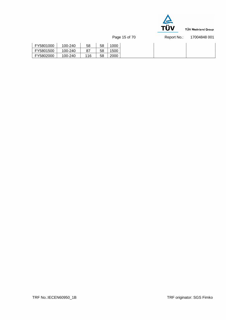
FY5800300 100-240 17.4 58 300 FY5800400 100-240 23.2 58 400 FY5800500 100-240 29 58 500 FY5800600 100-240 34.8 58 600 FY5800700 100-240 40.6 58 700 FY5800800 100-240 46.4 58 800 FY5800900 100-240 52.2 58 900
2X0.9MM 14T
16A 200V
330uF 63V
Page 15 of 70
Report No.: 17004848 001
TRF No.:IECEN60950_1B TRF originator: SGS Fimko
FY5801000 100-240 58 58 1000 FY5801500 100-240 87 58 1500 FY5802000 100-240 116 58 2000

Page 16 of 70
Report No.: 17004848 001
TRF No.:IECEN60950_1B TRF originator: SGS Fimko
IEC 60950-1 / EN 60950-1
Clause Requirement – Test Result – Remark Verdict
1 GENERAL P
1.5 Components P
1.5.1 General P
Comply with IEC 60950 or relevant component standard
Components which were found to affect safety aspects comply with the requirements of this standard or within the safety aspects of the relevant IEC component standards. (see appended table 1.5.1)
P
1.5.2 Evaluation and testing of components Components which are certified to IEC and /or national standards are used correctly within their ratings. Components not covered by IEC standards are tested under the conditions present in the equipment.
P
1.5.3 Thermal controls No thermal controls used. P
1.5.4 Transformers Transformer complies with the relevant requirements of this standard, particularly those of Annex C.
P
1.5.5 Interconnecting cables SELV output cable provided as part of this equipment and no higher energy levels than 240VA, it is not possible to present a hazard.
P
1.5.6 Capacitors in primary circuits ............................... : X2-cap (C1) used between L and N complies with the requirements of IEC 60384-14: 1993.
P
1.5.7 Double insulation or reinforced insulation bridged by components
See below P
1.5.7.1 General P
1.5.7.2 Bridging capacitors Y1-cap (C9) complying with IEC 60384-14: 1993 provided to bridge double/reinforced insulation.
P
1.5.7.3 Bridging resistors No such resistors used. N/A

Page 17 of 70
Report No.: 17004848 001
TRF No.:IECEN60950_1B TRF originator: SGS Fimko
IEC 60950-1 / EN 60950-1
Clause Requirement – Test Result – Remark Verdict
1.5.7.4 Accessible parts The accessible conductive parts and circuits on secondary complied with the requirements of 2.4 after performing electric strength test of insulation between primary and accessible parts.
P
1.5.8 Components in equipment for IT power systems Not for IT power systems N/A
1.6 Power interface P
1.6.1 AC power distribution systems TN power distribution system. P
1.6.2 Input current (see appended table 1.6.2) P
1.6.3 Voltage limit of hand-held equipment Not hand-held equipment N/A
1.6.4 Neutral conductor The neutral conductor was insulated from the body throughout the equipment as if it was a line conductor.
P
1.7 Marking and instructions P
1.7.1 Power rating See below P
Rated voltage(s) or voltage range(s) (V) ............. : 100-240V~ P
Symbol for nature of supply, for d.c. only ............. : AC supply only N/A
Rated frequency or rated frequency range (Hz) ..: 50/60Hz P
Rated current (mA or A) ...................................... : 2.5A P
Manufacturer’s name or trademark or identification mark ..................................................................... :
See page 3 P
Type/model or type reference............................... : See page 5-15 P
Symbol for Class II equipment only ..................... : See page 3 P
Other symbols ...................................................... : Additional symbols or markings do not give rise to misunderstanding.
P
Certification marks ............................................... : See page 3 P
1.7.2 Safety instructions N/A
1.7.3 Short duty cycles Continuous operation N/A
1.7.4 Supply voltage adjustment ................................... : Supply voltage not adjustable N/A
Methods and means of adjustment; reference to installation instructions ......................................... :
N/A
1.7.5 Power outlets on the equipment .......................... : No power outlets N/A

Page 18 of 70
Report No.: 17004848 001
TRF No.:IECEN60950_1B TRF originator: SGS Fimko
IEC 60950-1 / EN 60950-1
Clause Requirement – Test Result – Remark Verdict
1.7.6 Fuse identification (marking, special fusing characteristics, cross-reference) ......................... :
Soldered-in fuse not located in operator access area, “CF1 3.15A, 250V” marked close to current fuse on PCB.
P
1.7.7 Wiring terminals N/A
1.7.7.1 Protective earthing and bonding terminals .......... : Class II equipment N/A
1.7.7.2 Terminal for a.c. mains supply conductors This equipment is not permanently connected equipment or provided with ordinary non-detachable power supply cords.
N/A
1.7.7.3 Terminals for d.c. mains supply conductors Not DC mains supplied. N/A
1.7.8 Controls and indicators No controls and indicators N/A
1.7.8.1 Identification, location and marking ..................... : N/A
1.7.8.2 Colours ............................................................... : No safety relevant colours used.
N/A
1.7.8.3 Symbols according to IEC 60417 .........................: N/A
1.7.8.4 Markings using figures ........................................: No figures used for marking N/A
1.7.9 Isolation of multiple power sources .....................: Single power source N/A
1.7.10 IT power distribution systems N/A
1.7.11 Thermostats and other regulating devices No manually adjustable /resettable devices used
N/A
1.7.12 Language(s) ......................................................... : English
1.7.13 Durability The label was subjected to the permanence of marking test. The label was rubbed with cloth soaked with water for 15 sec. And then again for 15 sec. with the cloth soaked with petroleum spirit.
After this test there was no damage to the label. The marking on the label did not fade. There was no curling nor lifting of the label edge.
P
1.7.14 Removable parts No removable parts used N/A
1.7.15 Replaceable batteries No replaceable batteries used N/A
Language(s)..........................................................:
1.7.16 Operator access with a tool .................................. : N/A
1.7.17 Equipment for restricted access locations............ : Not equipment for restricted access location
N/A

Page 19 of 70
Report No.: 17004848 001
TRF No.:IECEN60950_1B TRF originator: SGS Fimko
IEC 60950-1 / EN 60950-1
Clause Requirement – Test Result – Remark Verdict
2 PROTECTION FROM HAZARDS P
2.1 Protection from electric shock and energy hazards P
2.1.1 Protection in operator access areas P
2.1.1.1 Access to energized parts Protection provided by enclosure without any openings.
P
Test by inspection ................................................: P
Test with test finger ..............................................: 30N applied P
Test with test pin ..................................................: P
Test with test probe .............................................: No TNV N/A
2.1.1.2 Battery compartments .........................................: No battery compartments used. N/A
2.1.1.3 Access to ELV wiring No ELV wiring used. N/A
Working voltage (Vpeak or Vrms); minimum distance (mm) through insulation
2.1.1.4 Access to hazardous voltage circuit wiring No hazardous voltage circuit wiring accessible.
N/A
2.1.1.5 Energy hazards ....................................................: Energy was less than 240VA as measured, also see appended table 2.1.1.5.
P
2.1.1.6 Manual controls No manual controls N/A
2.1.1.7 Discharge of capacitors in equipment Not tested because of X2-cap C1 = 0.1µF
N/A
Time-constant (s); measured voltage (V) .............:
2.1.2 Protection in service access areas Service not considered since the enclosure was ultra-sonic welded.
N/A
2.1.3 Protection in restricted access locations No restricted access locations N/A
2.2 SELV circuits P
2.2.1 General requirements P
2.2.2 Voltages under normal conditions (V) ..................: No voltage exceeded 42.4 V peak, or 60 V d.c. under normal operation condition in secondary SELV circuits.
P
2.2.3 Voltages under fault conditions (V).......................: No voltage exceeded a limit of 71 V peak, or 120 V d.c. within 0.2 s and 42.4 V peak, or 60V d.c. for longer than 0.2 s on secondary SELV circuits under single fault condition.
P

Page 20 of 70
Report No.: 17004848 001
TRF No.:IECEN60950_1B TRF originator: SGS Fimko
IEC 60950-1 / EN 60950-1
Clause Requirement – Test Result – Remark Verdict
2.2.3.1 Separation by double insulation or reinforced insulation (method 1)
Method 1 used. P
2.2.3.2 Separation by earthed screen (method 2) N/A
2.2.3.3 Protection by earthing of the SELV circuit (method 3)
N/A
2.2.4 Connection of SELV circuits to other circuits........: SELV circuits only considered for connection to SELV circuits.
P
2.3 TNV circuits (No TNV circuits) N/A
2.3.1 Limits N/A
Type of TNV circuits .............................................:
2.3.2 Separation from other circuits and from accessible parts
N/A
Insulation employed..............................................:
2.3.3 Separation from hazardous voltages N/A
Insulation employed..............................................:
2.3.4 Connection of TNV circuits to other circuits N/A
Insulation employed..............................................:
2.3.5 Test for operating voltages generated externally N/A
2.4 Limited current circuits P
2.4.1 General requirements Primary and secondary circuits bridged by a Y1 type capacitor. Secondary circuit tested as limited current circuits.
P
2.4.2 Limit values See appended table 2.4.2 P
Frequency (Hz) .....................................................:
Measured current (mA).........................................:
Measured voltage (V) ...........................................:
Measured capacitance (µF)..................................:
2.4.3 Connection of limited current circuits to other circuits
Only intended to be connected with SELV circuits.
P
2.5 Limited power sources (Not required) N/A
Inherently limited output N/A
Impedance limited output N/A
Overcurrent protective device limited output N/A
Page 21 of 70
Report No.: 17004848 001
TRF No.:IECEN60950_1B TRF originator: SGS Fimko
IEC 60950-1 / EN 60950-1
Clause Requirement – Test Result – Remark Verdict
Regulating network limited output under normal operating and single fault condition
N/A
Regulating network limited output under normal operating conditions and overcurrent protective device limited output under single fault condition
N/A
Output voltage (V), output current (A), apparent power (VA)............................................................:
Current rating of overcurrent protective device (A)
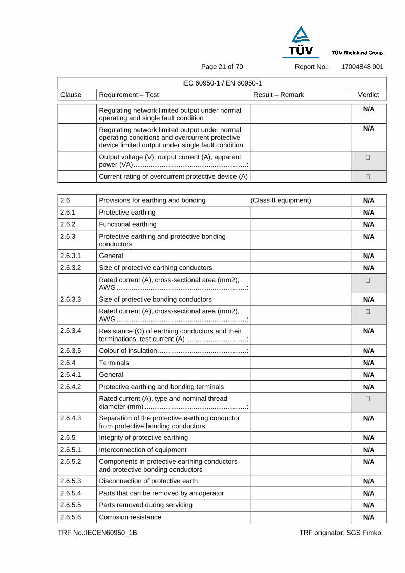
2.6 Provisions for earthing and bonding (Class II equipment) N/A
2.6.1 Protective earthing N/A
2.6.2 Functional earthing N/A
2.6.3 Protective earthing and protective bonding conductors
N/A
2.6.3.1 General N/A
2.6.3.2 Size of protective earthing conductors N/A
Rated current (A), cross-sectional area (mm2), AWG.....................................................................:
2.6.3.3 Size of protective bonding conductors N/A
Rated current (A), cross-sectional area (mm2), AWG.....................................................................:
2.6.3.4 Resistance (Ω) of earthing conductors and their terminations, test current (A) ................................:
N/A
2.6.3.5 Colour of insulation ...............................................: N/A
2.6.4 Terminals N/A
2.6.4.1 General N/A
2.6.4.2 Protective earthing and bonding terminals N/A
Rated current (A), type and nominal thread diameter (mm) ......................................................:
2.6.4.3 Separation of the protective earthing conductor from protective bonding conductors
N/A
2.6.5 Integrity of protective earthing N/A
2.6.5.1 Interconnection of equipment N/A
2.6.5.2 Components in protective earthing conductors and protective bonding conductors
N/A
2.6.5.3 Disconnection of protective earth N/A
2.6.5.4 Parts that can be removed by an operator N/A
2.6.5.5 Parts removed during servicing N/A
2.6.5.6 Corrosion resistance N/A
Page 22 of 70
Report No.: 17004848 001
TRF No.:IECEN60950_1B TRF originator: SGS Fimko
IEC 60950-1 / EN 60950-1
Clause Requirement – Test Result – Remark Verdict
2.6.5.7 Screws for protective bonding N/A
2.6.5.8 Reliance on telecommunication network or cable distribution system
N/A
2.7 Overcurrent and earth fault protection in primary circuits P
2.7.1 Basic requirements A soldered-in fuse located in circuits used as protective device against overcurrents, short circuits. Circuits breaker in building installation used as backup protection.
P
Instructions when protection relies on building installation
Pluggable equipment type A N/A
2.7.2 Faults not covered in 5.3 All faults considered for this equipment
N/A
2.7.3 Short-circuit backup protection The building installation considered as providing short-circuit backup protection
P
2.7.4 Number and location of protective devices ..........: Overcurrent protection by one built-in fuse.
P
2.7.5 Protection by several devices Only one fuse. N/A
2.7.6 Warning to service personnel ...............................: Service not considered for this ultra-sonic welded switching power supply.
N/A
2.8 Safety interlocks (No safety interlock used) N/A
2.8.1 General principles N/A
2.8.2 Protection requirements N/A
2.8.3 Inadvertent reactivation N/A
2.8.4 Fail-safe operation N/A
2.8.5 Moving parts N/A
2.8.6 Overriding N/A
2.8.7 Switches and relays N/A
2.8.7.1 Contact gaps (mm) ..............................................: N/A
2.8.7.2 Overload test N/A
2.8.7.3 Endurance test N/A
2.8.7.4 Electric strength test N/A
2.8.8 Mechanical actuators N/A

Page 23 of 70
Report No.: 17004848 001
TRF No.:IECEN60950_1B TRF originator: SGS Fimko
IEC 60950-1 / EN 60950-1
Clause Requirement – Test Result – Remark Verdict
2.9 Electrical insulation P
2.9.1 Properties of insulating materials Natural rubber, asbestos or hygroscopic material is not used.
P
2.9.2 Humidity conditioning 30°C, 95% R.H. for 48h P
Humidity (%) ........................................................:
Temperature (°C) .................................................:
2.9.3 Grade of insulation The adequate levels of safety insulation is provided and maintained to comply with the requirements of this standard.
P
2.10 Clearances, creepage distances and distances through insulation P
2.10.1 General P
2.10.2 Determination of working voltage (see appended table 2.10.2) P
2.10.3 Clearances (see appended table 2.10.3 and 2.10.4)
P
2.10.3.1 General P
2.10.3.2 Clearances in primary circuits (see appended table 2.10.3 and 2.10.4)
P
2.10.3.3 Clearances in secondary circuits N
2.10.3.4 Measurement of transient voltage levels N
2.10.4 Creepage distances (see appended table 2.10.3 and 2.10.4)
P
CTI tests ...............................................................:
2.10.5 Solid insulation Considered for enclosure and opto-coupler.
P
2.10.5.1 Minimum distance through insulation (see appended table 2.10.5) P
2.10.5.2 Thin sheet material See below P
Page 24 of 70
Report No.: 17004848 001
TRF No.:IECEN60950_1B TRF originator: SGS Fimko
IEC 60950-1 / EN 60950-1
Clause Requirement – Test Result – Remark Verdict
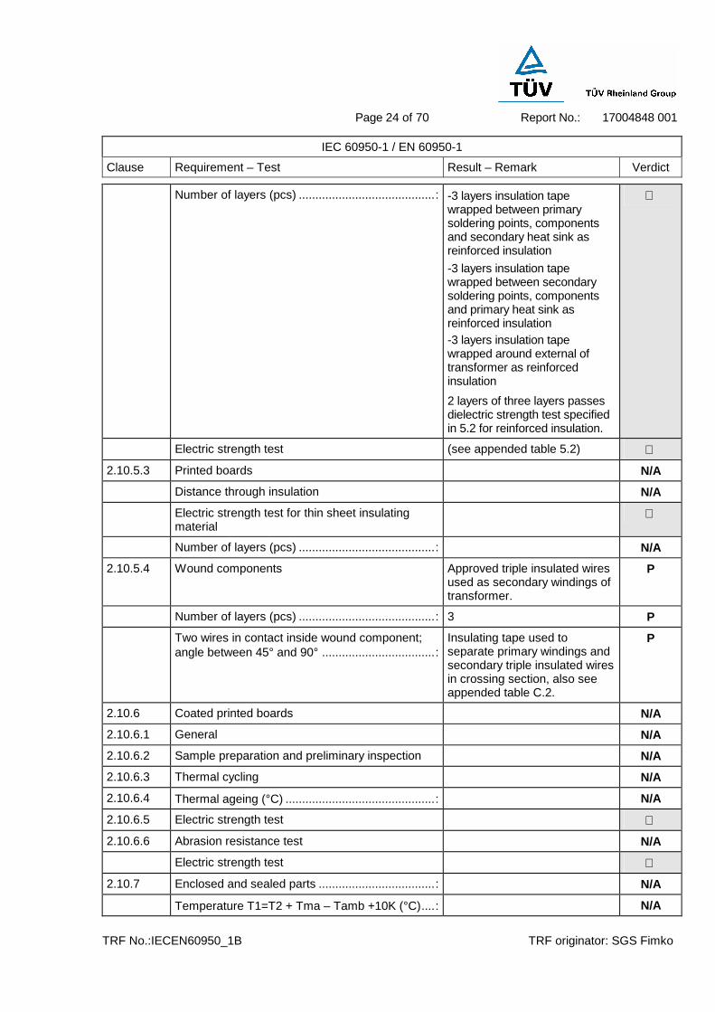
Number of layers (pcs) .........................................: -3 layers insulation tape wrapped between primary soldering points, components and secondary heat sink as reinforced insulation
-3 layers insulation tape wrapped between secondary soldering points, components and primary heat sink as reinforced insulation -3 layers insulation tape wrapped around external of transformer as reinforced insulation
2 layers of three layers passes dielectric strength test specified in 5.2 for reinforced insulation.
Electric strength test (see appended table 5.2)
2.10.5.3 Printed boards N/A
Distance through insulation N/A
Electric strength test for thin sheet insulating material
Number of layers (pcs) .........................................: N/A
2.10.5.4 Wound components Approved triple insulated wires used as secondary windings of transformer.
P
Number of layers (pcs) .........................................: 3 P
Two wires in contact inside wound component; angle between 45° and 90° ..................................:
Insulating tape used to separate primary windings and secondary triple insulated wires in crossing section, also see appended table C.2.
P
2.10.6 Coated printed boards N/A
2.10.6.1 General N/A
2.10.6.2 Sample preparation and preliminary inspection N/A
2.10.6.3 Thermal cycling N/A
2.10.6.4 Thermal ageing (°C) .............................................: N/A
2.10.6.5 Electric strength test
2.10.6.6 Abrasion resistance test N/A
Electric strength test
2.10.7 Enclosed and sealed parts ...................................: N/A
Temperature T1=T2 + Tma – Tamb +10K (°C)....: N/A
Page 25 of 70
Report No.: 17004848 001
TRF No.:IECEN60950_1B TRF originator: SGS Fimko
IEC 60950-1 / EN 60950-1
Clause Requirement – Test Result – Remark Verdict
2.10.8 Spacings filled by insulating compound................: Opto-coupler is approved component. Other components not applied for. (See appended table 2.10.5)
P
Electric strength test (see appended table 5.2)
2.10.9 Component external terminations N/A
2.10.10 Insulation with varying dimensions Insulation kept homogenous. N/A
3 WIRING, CONNECTIONS AND SUPPLY P
3.1 General P
3.1.1 Current rating and overcurrent protection All internal wires are UL listed and PVC insulated, and the cross-section area of which are adequate for the current they are intended to carry.
P
3.1.2 Protection against mechanical damage Wires do not touch sharp edges which could damage the insulation and cause hazards.
P
3.1.3 Securing of internal wiring Internal wires reliably soldered and fixed by gule.
P
3.1.4 Insulation of conductors The insulation of the individual conductors suitable for the application and the working voltage. For the insulation material see 3.1.1 and 3.1.10
P
3.1.5 Beads and ceramic insulators No beads and ceramic insulators
N/A
3.1.6 Screws for electrical contact pressure No screws for electrical contact pressure
N/A
3.1.7 Insulating materials in electrical connections Contact pressure is not transmitted through insulating material.
N/A
3.1.8 Self-tapping and spaced thread screws No self-tapping and spaced thread screws used
N/A
3.1.9 Termination of conductors The conductors of internal wires tightly soldered and additionally fixed by glue.
P
10 N pull test Applied. P
3.1.10 Sleeving on wiring No sleeving used as supplementary insulation on internal wire.
N/A
3.2 Connection to an a.c. mains supply or a d.c. mains supply P
Page 26 of 70
Report No.: 17004848 001
TRF No.:IECEN60950_1B TRF originator: SGS Fimko
IEC 60950-1 / EN 60950-1
Clause Requirement – Test Result – Remark Verdict
3.2.1 Means of connection ............................................: AC inlet used P
3.2.1.1 Connection to an a.c. mains supply P
3.2.1.2 Connection to a d.c. mains supply Not connected to d.c. mains supply
N/A
3.2.2 Multiple supply connections Single supply N/A
3.2.3 Permanently connected equipment Not permanently connected N/A
Number of conductors, diameter (mm) of cable and conduits ........................................................:
3.2.4 Appliance inlets VDE approved AC inlet used P
3.2.5 Power supply cords No power supply cord provided N/A
3.2.5.1 AC power supply cords N/A
Type......................................................................:
Rated current (A), cross-sectional area (mm2), AWG.....................................................................:
3.2.5.2 DC power supply cords N/A
3.2.6 Cord anchorages and strain relief No cord anchorage N/A
Mass of equipment (kg), pull (N) ........................:
Longitudinal displacement (mm) ..........................:
3.2.7 Protection against mechanical damage No power cords used N/A
3.2.8 Cord guards N/A
D (mm); test mass (g) ..........................................:
Radius of curvature of cord (mm).........................:
3.2.9 Supply wiring space No such supply wirings N/A
3.3 Wiring terminals for connection of external conductors (AC inlet used) N/A
3.3.1 Wiring terminals N/A
3.3.2 Connection of non-detachable power supply cords
N/A
3.3.3 Screw terminals N/A
3.3.4 Conductor sizes to be connected N/A
Rated current (A), cord/cable type, cross-sectional area (mm2) ...........................................................:
3.3.5 Wiring terminal sizes N/A
Rated current (A), type and nominal thread diameter (mm) .....................................................:
3.3.6 Wiring terminals design N/A
3.3.7 Grouping of wiring terminals N/A

Page 27 of 70
Report No.: 17004848 001
TRF No.:IECEN60950_1B TRF originator: SGS Fimko
IEC 60950-1 / EN 60950-1
Clause Requirement – Test Result – Remark Verdict
3.3.8 Stranded wire N/A
3.4 Disconnection from the mains supply P
3.4.1 General requirement P
3.4.2 Disconnect devices AC inlet used P
3.4.3 Permanently connected equipment Not permanently connected equipment
N/A
3.4.4 Parts which remain energized No parts remained energized after disconnection of the appliance coupler.
N/A
3.4.5 Switches in flexible cords No power cord N/A
3.4.6 Single-phase equipment and d.c. equipment The appliance coupler disconnects both poles simultaneously
P
3.4.7 Three-phase equipment Not three-phase equipment N/A
3.4.8 Switches as disconnect devices No switches used N/A
3.4.9 Plugs as disconnect devices AC inlet used N/A
3.4.10 Interconnected equipment No such equipment N/A
3.4.11 Multiple power sources Only one power source NA
3.5 Interconnection of equipment P
3.5.1 General requirements P
3.5.2 Types of interconnection circuits ..........................: Interconnection circuits are SELV Circuit and Limited Current Circuit.
P
3.5.3 ELV circuits as interconnection circuits No ELV circuits N/A
4 PHYSICAL REQUIREMENTS P
4.1 Stability P
Angle of 10° P
Test: force (N).......................................................: Mass: less than 0.32kg N/A
4.2 Mechanical strength P
4.2.1 General P
4.2.2 Steady force test, 10 N Performed on internal components
P
4.2.3 Steady force test, 30 N No internal enclosure N/A
4.2.4 Steady force test, 250 N Performed on enclosure P

Page 28 of 70
Report No.: 17004848 001
TRF No.:IECEN60950_1B TRF originator: SGS Fimko
IEC 60950-1 / EN 60950-1
Clause Requirement – Test Result – Remark Verdict
4.2.5 Impact test 1.3m, 500g, 3times, after the test compliance was checked by 4.2.1
P
Fall test Performed. P
Swing test Performed. P
4.2.6 Drop test See 4.2.5 N/A
4.2.7 Stress relief test 93(=82.2+10)°C, 7 hours P
4.2.8 Cathode ray tubes No CRT. N/A
Picture tube separately certified ...........................: N/A
4.2.9 High pressure lamps No high pressure lamps N/A
4.2.10 Wall or ceiling mounted equipment; force (N) .....: Not such equipment N/A
4.3 Design and construction P
4.3.1 Edges and corners No sharp edges or corners P
4.3.2 Handles and manual controls; force (N) ...............: No handles and manual controls used
N/A
4.3.3 Adjustable controls No adjustable controls N/A
4.3.4 Securing of parts No connection likely to expose to machanical stress
P
4.3.5 Connection of plugs and sockets Output connectors does not comply with IEC 60083 or IEC 60320
P
4.3.6 Direct plug-in equipment Not direct plug-in equipment N/A
Dimensions (mm) of mains plug for direct plug-in : N/A
Torque and pull test of mains plug for direct plug-in; torque (Nm); pull (N) ................................:
N/A
4.3.7 Heating elements in earthed equipment No heating elements used N/A
4.3.8 Batteries No batteries used N/A
4.3.9 Oil and grease N/A
4.3.10 Dust, powders, liquids and gases N/A
4.3.11 Containers for liquids or gases N/A
4.3.12 Flammable liquids.................................................: N/A
Quantity of liquid (l) ...............................................: N/A
Flash point (°C).....................................................: N/A
4.3.13 Radiation; type of radiation ..................................: See 4.3.13.5 P
4.3.13.1 General N/A
4.3.13.2 Ionizing radiation No ionizing radiation N/A

Page 29 of 70
Report No.: 17004848 001
TRF No.:IECEN60950_1B TRF originator: SGS Fimko
IEC 60950-1 / EN 60950-1
Clause Requirement – Test Result – Remark Verdict
Measured radiation (pA/kg) ................................. :
Measured high-voltage (kV) ................................ :
Measured focus voltage (kV) ............................... :
CRT markings ..................................................... :
4.3.13.3 Effect of ultraviolet (UV) radiation on materials No ultraviolet radiation N/A
Part, property, retention after test, flammability classification ........................................................:
N/A
4.3.13.4 Human exposure to ultraviolet (UV) radiation ......: N/A
4.3.13.5 Laser (including LEDs) The LED for indication considered as inherently LED Class 1.
P
Laser class ...........................................................: Class 1
4.3.13.6 Other types ..........................................................: N/A
4.4 Protection against hazardous moving parts (No hazardous moving parts used) N/A
4.4.1 General N/A
4.4.2 Protection in operator access areas N/A
4.4.3 Protection in restricted access locations N/A
4.4.4 Protection in service access areas N/A
4.5 Thermal requirements P
4.5.1 Maximum temperatures (see appended table 4.5.1) P
Normal load condition per Annex L.......................: See table 1.6.2. P
4.5.2 Resistance to abnormal heat (see appended table 4.5.2) P
4.6 Openings in enclosures P
4.6.1 Top and side openings No openings P
Dimensions (mm) ................................................:
4.6.2 Bottoms of fire enclosures No openings P
Construction of the bottom ...................................:
4.6.3 Doors or covers in fire enclosures N/A
4.6.4 Openings in transportable equipment N/A
4.6.5 Adhesives for constructional purposes N/A
Conditioning temperature (°C)/time (weeks) ........:
4.7 Resistance to fire P

Page 30 of 70
Report No.: 17004848 001
TRF No.:IECEN60950_1B TRF originator: SGS Fimko
IEC 60950-1 / EN 60950-1
Clause Requirement – Test Result – Remark Verdict
4.7.1 Reducing the risk of ignition and spread of flame P
Method 1, selection and application of components wiring and materials
Use of materials complies with the required flammbility classes which are detailed in 4.7.2 and 4.7.3, in addition, the simulated faults of 5.3.6 are applied.
P
Method 2, application of all of simulated fault condition tests
N/A
4.7.2 Conditions for a fire enclosure With having the following parts: Components in primary circuits Components in secondary circuits not supplied by limited power source Insulated wiring
The fire enclosure is required.
P
4.7.2.1 Parts requiring a fire enclosure See above P
4.7.2.2 Parts not requiring a fire enclosure N/A
4.7.3 Materials P
4.7.3.1 General P
4.7.3.2 Materials for fire enclosures Fire enclosure with flammability of V-0.
P
4.7.3.3 Materials for components and other parts outside fire enclosures
PVC insulated output cable with class VW-1
P
4.7.3.4 Materials for components and other parts inside fire enclosures
Internal components except small parts are V-2, HF-2 or better.
P
4.7.3.5 Materials for air filter assemblies N/A
4.7.3.6 Materials used in high-voltage components No high-voltage components N/A
5 ELECTRICAL REQUIREMENTS AND SIMULATED ABNORMAL CONDITIONS P
5.1 Touch current and protective conductor current P
5.1.1 General See sub-clauses 5.1.2 to 5.1.6. P
5.1.2 Equipment under test (EUT) EUT has only one mains connection.
P
5.1.3 Test circuit Use of figure 5A. P
5.1.4 Application of measuring instrument Using measuring instrument figure D.1 in annex D.
P

Page 31 of 70
Report No.: 17004848 001
TRF No.:IECEN60950_1B TRF originator: SGS Fimko
IEC 60950-1 / EN 60950-1
Clause Requirement – Test Result – Remark Verdict
5.1.5 Test procedure The test was carried out on the EUT with terminal A of measuring network figure D.1 connected via measurement switch “s” to enclosure, output terminal of the EUT respectively.
P
5.1.6 Test measurements P
Test voltage (V) ...................................................: See appended table 5.1.6.
Measured touch current (mA) ..............................: See appended table 5.1.6.
Max. allowed touch current (mA) .........................: See appended table 5.1.6.
Measured protective conductor current (mA) ......:
Max. allowed protective conductor current (mA) .:
5.1.7 Equipment with touch current exceeding 3.5 mA : Touch current dose not exceed 3.5 mA.
N/A
5.1.8 Touch currents to and from telecommunication networks and cable distribution systems and from telecommunication networks
No TNV. N/A
5.1.8.1 Limitation of the touch current to a telecommunication network and a cable distribution system
N/A
Test voltage (V) ...................................................:
Measured touch current (mA) ..............................:
Max. allowed touch current (mA) .........................:
5.1.8.2 Summation of touch currents from telecommunication networks ................................:
N/A
5.2 Electric strength P
5.2.1 General (see appended table 5.2) P
5.2.2 Test procedure (see appended table 5.2) P
5.3 Abnormal operating and fault conditions P
5.3.1 Protection against overload and abnormal operation
(See appended table 5.3) P
5.3.2 Motors No motors used N/A
5.3.3 Transformers Safety isolating transformer used, see table 5.3 for overload test and Annex C for construction
P
5.3.4 Functional insulation .............................................: By short-circuit, for results see appended table 5.3
P

Page 32 of 70
Report No.: 17004848 001
TRF No.:IECEN60950_1B TRF originator: SGS Fimko
IEC 60950-1 / EN 60950-1
Clause Requirement – Test Result – Remark Verdict
5.3.5 Electromechanical components No electromechanical component.
N/A
5.3.6 Simulation of faults (See appended table 5.3.) P
5.3.7 Unattended equipment No unattended equipment N/A
5.3.8 Compliance criteria for abnormal operating and fault conditions
No fire or molten metal occurred and no deformation of enclosure during the tests. No reduction of clearance and creepage distance. Electric strength test is made on reinforced insulation after test
P
6 CONNECTION TO TELECOMMUNICATION NETWORKS (No TNV circuits) N/A
6.1 Protection of telecommunication network service persons, and users of other equipment connected to the network, from hazards in the equipment
N/A
6.1.1 Protection from hazardous voltages N/A
6.1.2 Separation of the telecommunication network from earth N/A
6.1.2.1 Requirements N/A
Test voltage (V) ...................................................:
Current in the test circuit (mA) ............................:
6.1.2.2 Exclusions.............................................................: N/A
6.2 Protection of equipment users from overvoltages on telecommunication networks N/A
6.2.1 Separation requirements N/A
6.2.2 Electric strength test procedure N/A
6.2.2.1 Impulse test N/A
6.2.2.2 Steady-state test N/A
6.2.2.3 Compliance criteria N/A
6.3 Protection of the telecommunication wiring system from overheating N/A
Max. output current (A) .........................................:
Current limiting method ........................................:
7 CONNECTION TO CABLE DISTRIBUTION SYSTEMS (No such system) N/A
7.1 Protection of cable distribution system service persons, and users of other equipment connected to the system, from hazardous voltages in the equipment
N/A

Page 33 of 70
Report No.: 17004848 001
TRF No.:IECEN60950_1B TRF originator: SGS Fimko
IEC 60950-1 / EN 60950-1
Clause Requirement – Test Result – Remark Verdict
7.2 Protection of equipment users from overvoltages on the cable distribution system
N/A
7.3 Insulation between primary circuits and cable distribution systems
N/A
7.3.1 General N/A
7.3.2 Voltage surge test N/A
7.3.3 Impulse test N/A
A ANNEX A, TESTS FOR RESISTANCE TO HEAT AND FIRE P
A.1 Flammability test for fire enclosures of movable equipment having a total mass exceeding 18 kg, and of stationary equipment (see 4.7.3.2)
N/A
A.1.1 Samples................................................................:
Wall thickness (mm).............................................:
A.1.2 Conditioning of samples; temperature (°C) ..........: N/A
A.1.3 Mounting of samples ............................................: N/A
A.1.4 Test flame (see IEC 60695-11-3) N/A
Flame A, B, C or D ...............................................:
A.1.5 Test procedure N/A
A.1.6 Compliance criteria N/A
Sample 1 burning time (s) ....................................:
Sample 2 burning time (s) ....................................:
Sample 3 burning time (s) ....................................:
A.2 Flammability test for fire enclosures of movable equipment having a total mass not exceeding 18 kg, and for material and components located inside fire enclosures (see 4.7.3.2 and 4.7.3.4) (UL listed materials used, see appended table 1.5.1)
P
A.2.1 Samples, material .................................................:
Wall thickness (mm).............................................:
A.2.2 Conditioning of samples N/A
A.2.3 Mounting of samples ...........................................: N/A
A.2.4 Test flame (see IEC 60695-11-4) N/A
Flame A, B or C ...................................................:
A.2.5 Test procedure N/A
A.2.6 Compliance criteria N/A
Sample 1 burning time (s) ....................................:
Sample 2 burning time (s) ....................................:
Sample 3 burning time (s) ....................................:

Page 34 of 70
Report No.: 17004848 001
TRF No.:IECEN60950_1B TRF originator: SGS Fimko
IEC 60950-1 / EN 60950-1
Clause Requirement – Test Result – Remark Verdict
A.2.7 Alternative test acc. to IEC 60695-2-2, cl. 4 and 8 N/A
Sample 1 burning time (s) ....................................:
Sample 2 burning time (s) ....................................:
Sample 3 burning time (s) ....................................:
A.3 Hot flaming oil test (see 4.6.2) N/A
A.3.1 Mounting of samples N/A
A.3.2 Test procedure N/A
A.3.3 Compliance criterion N/A
B ANNEX B, MOTOR TESTS UNDER ABNORMAL CONDITIONS (see 4.7.2.2 and 5.3.2) (No motor used)
N/A
B.1 General requirements N/A
Position ................................................................:
Manufacturer ........................................................:
Type .....................................................................:
Rated values .......................................................:
B.2 Test conditions N/A
B.3 Maximum temperatures N/A
B.4 Running overload test N/A
B.5 Locked-rotor overload test N/A
Test duration (days) .............................................:
Electric strength test: test voltage (V) ..................:
B.6 Running overload test for d.c. motors in secondary circuits
N/A
B.7 Locked-rotor overload test for d.c. motors in secondary circuits N/A
B.7.1 Test procedure N/A
B.7.2 Alternative test procedure; test time (h)................: N/A
B.7.3 Electric strength test N/A
B.8 Test for motors with capacitors N/A
B.9 Test for three-phase motors N/A
B.10 Test for series motors N/A
Operating voltage (V) ...........................................:
C ANNEX C, TRANSFORMERS (see 1.5.4 and 5.3.3) P
Position ................................................................: PT1

Page 35 of 70
Report No.: 17004848 001
TRF No.:IECEN60950_1B TRF originator: SGS Fimko
IEC 60950-1 / EN 60950-1
Clause Requirement – Test Result – Remark Verdict
Manufacturer ........................................................: Fuyuan Electronic Co.,Ltd
Type .....................................................................: See 1.5.1
Rated values .......................................................: Class B
Method of protection .............................................: Over-current protection
C.1 Overload test See appended table 5.3 P
C.2 Insulation See appended table C.2 P
Protection from displacement of windings ............: Bobbin, insulation tape P
D ANNEX D, MEASURING INSTRUMENTS FOR TOUCH-CURRENT TESTS (see 5.1.4)
P
D.1 Measuring instrument ANNEX D figure D.1 P
D.2 Alternative measuring instrument N/A
E ANNEX E, TEMPERATURE RISE OF A WINDING (see 1.4.13) N/A
F ANNEX F, MEASUREMENT OF CLEARANCES AND CREEPAGE DISTANCES (see 2.10)
P
G ANNEX G, ALTERNATIVE METHOD FOR DETERMINING MINIMUM CLEARANCES
N/A
G.1 Summary of the procedure for determining minimum clearances
N/A
G.2 Determination of mains transient voltage (V) .......: N/A
G.2.1 AC mains supply N/A
G.2.2 DC mains supply N/A
G.3 Determination of telecommunication network transient voltage (V)..............................................:
N/A
G.4 Determination of required withstand voltage (V)...: N/A
G.5 Measurement of transient levels (V).....................: N/A
G.6 Determination of minimum clearances .................: N/A
H ANNEX H, IONIZING RADIATION (see 4.3.13) N/A
J ANNEX J, TABLE OF ELECTROCHEMICAL POTENTIALS (see 2.6.5.6) N/A
Metal used ...........................................................:

Page 36 of 70
Report No.: 17004848 001
TRF No.:IECEN60950_1B TRF originator: SGS Fimko
IEC 60950-1 / EN 60950-1
Clause Requirement – Test Result – Remark Verdict
K ANNEX K, THERMAL CONTROLS (see 1.5.3 and 5.3.7) N/A
K.1 Making and breaking capacity N/A
K.2 Thermostat reliability; operating voltage (V) .........: N/A
K.3 Thermostat endurance test; operating voltage (V) .......................................................................:
N/A
K.4 Temperature limiter endurance; operating voltage (V) ........................................................................:
N/A
K.5 Thermal cut-out reliability N/A
K.6 Stability of operation N/A
L ANNEX L, NORMAL LOAD CONDITIONS FOR SOME TYPES OF ELECTRICAL BUSINESS EQUIPMENT (see 1.2.2.1 and 4.5.1)
P
L.1 Typewriters N/A
L.2 Adding machines and cash registers N/A
L.3 Erasers N/A
L.4 Pencil sharpeners N/A
L.5 Duplicators and copy machines N/A
L.6 Motor-operated files N/A
L.7 Other business equipment Test with unit connected to rated output current
P
M ANNEX M, CRITERIA FOR TELEPHONE RINGING SIGNALS (see 2.3.1) N/A
M.1 Introduction N/A
M.2 Method A N/A
M.3 Method B N/A
M.3.1 Ringing signal N/A
M.3.1.1 Frequency (Hz) ....................................................:
M.3.1.2 Voltage (V) ...........................................................:
M.3.1.3 Cadence; time (s), voltage (V) .............................:
M.3.1.4 Single fault current (mA).......................................:
M.3.2 Tripping device and monitoring voltage................: N/A
M.3.2.1 Conditions for use of a tripping device or a monitoring voltage
N/A
M.3.2.2 Tripping device N/A
M.3.2.3 Monitoring voltage (V)...........................................: N/A

Page 37 of 70
Report No.: 17004848 001
TRF No.:IECEN60950_1B TRF originator: SGS Fimko
IEC 60950-1 / EN 60950-1
Clause Requirement – Test Result – Remark Verdict
N ANNEX N, IMPULSE TEST GENERATORS (see 2.10.3.4, 6.2.2.1, 7.3.2 and clause G.5)
N/A
N.1 ITU-T impulse test generators N/A
N.2 IEC 60065 impulse test generator N/A
P ANNEX P, NORMATIVE REFERENCES P
Q ANNEX Q, BIBLIOGRAPHY P
R ANNEX R, EXAMPLES OF REQUIREMENTS FOR QUALITY CONTROL PROGRAMMES
N/A
R.1 Minimum separation distances for unpopulated coated printed boards (see 2.10.6)
N/A
R.2 Reduced clearances (see 2.10.3) N/A
S ANNEX S, PROCEDURE FOR IMPULSE TESTING (see 6.2.2.3) N/A
S.1 Test equipment N/A
S.2 Test procedure N/A
S.3 Examples of waveforms during impulse testing N/A
T ANNEX T, GUIDANCE ON PROTECTION AGAINST INGRESS OF WATER (see 1.1.2)
N/A
U ANNEX U, INSULATED WINDING WIRES FOR USE WITHOUT INTERLEAVED INSULATION (see 2.10.5.4)
P
VDE approved triple insulated wires used as secondary windings of transformer
V ANNEX V, AC POWER DISTRIBUTION SYSTEMS (see 1.6.1) P
V.1 Introduction N/A
V.2 TN power distribution systems TN power systems P
V.3 TT power systems N/A
V.4 IT power systems N/A
W ANNEX W, SUMMATION OF TOUCH CURRENTS N/A

Page 38 of 70
Report No.: 17004848 001
TRF No.:IECEN60950_1B TRF originator: SGS Fimko
IEC 60950-1 / EN 60950-1
Clause Requirement – Test Result – Remark Verdict
W.1 Touch current from electronic circuits N/A
W.1.2 Earthed circuits N/A
W.2 Interconnection of several equipments N/A
W.2.1 Isolation N/A
W.2.2 Common return, isolated from earth N/A
W.2.3 Common return, connected to protective earth N/A
X ANNEX X, MAXIMUM HEATING EFFECT IN TRANSFORMER TESTS (see clause C.1)
N/A
X.1 Determination of maximum input current N/A
X.2 Overload test procedure N/A
Y ANNEX Y, ULTRAVIOLET LIGHT CONDITIONING TEST (see 4.3.13.3) N/A
Y.1 Test apparatus .....................................................: N/A
Y.2 Mounting of test samples .....................................: N/A
Y.3 Carbon-arc light-exposure apparatus ..................: N/A
Y.4 Xenon-arc light exposure apparatus ....................: N/A

Page 39 of 70
Report No.: 17004848 001
TRF No.:IECEN60950_1B TRF originator: SGS Fimko
IEC 60950-1 / EN 60950-1
Clause Requirement – Test Result – Remark Verdict
CENELEC COMMON MODIFICATIONS [C], SPECIAL NATIONAL CONDITIONS [S] AND A-DEVIATIONS (NATIONAL DEVIATIONS) [A] (EN 60950-1:2001, Annex ZB and Annex ZC)
P
General C: Delete all the "country" notes in the reference document according to the following list:
1.1.5 Note 2 1.5.8 Note 2 1.6.1 Note 1.7.2 Note 4 1.7.12 Note 2 2.6 Note 2.2.3 Note 2.2.4 Note 2.3.2 Note 2, 7, 8 2.3.3 Note 1, 2 2.3.4 Note 2,3 2.7.1 Note 2.10.3.1 Note 4 3.2.1.1 Note 3.2.3 Note 1, 2 3.2.5.1 Note 2 4.3.6 Note 1,2 4.7.2.2 Note 4.7.3.1 Note 2 6.1.2.1 Note 6.1.2.2 Note 6.2.2 Note 6.2.2.1 Note 2 6.2.2.2 Note 7 Note 4 7.1 Note G2.1 Note 1, 2 Annex H Note 2
Deleted. P
1.2.4.1 S (DK): Certain types of Class I appliances (see 3.2.1.1) may be provided with a plug not establishing earthing conditions when inserted into Danish socket-outlets.
N/A
1.5.1 A (SE, Ordinance 1990:944 and CH, Ordinance on environmentally hazardous substances SR 814.013, Annex 3.2, Mercury): Add NOTE – Switches containing mercury such as thermostats, relays and level controllers are not allowed.
N/A
1.5.8 S (NO): Due to the IT power system used (see annex V, Fig. V.7), capacitors are required to be rated for the applicable line-to-line voltage (230 V).
N/A
1.7.2 S (FI, NO, SE): CLASS I PLUGGABLE EQUIPMENT TYPE A intended for connection to other equipment or a network shall, if safety relies on connection to protective earth or if surge suppressors are connected between the network terminals and accessible parts, have a marking stating that the equipment must be connected to an earthed mains socket-outlet.
The marking text in the applicable countries shall be as follows:
N/A
FI: "Laite on liitettävä suojamaadoituskoskettimilla varustettuun pistorasiaan"
N/A
NO: "Apparatet må tilkoples jordet stikkontakt" N/A
SE: "Apparaten skall anslutas till jordat uttag" N/A
A (DK, Heavy Current Regulations): Supply cords of class I equipment, which is delivered without a plug, must be provided with a visible tag with the following text:
Vigtigt! Lederen med grøn/gul isolation må kun tilsluttes en klemme mærket
N/A

Page 40 of 70
Report No.: 17004848 001
TRF No.:IECEN60950_1B TRF originator: SGS Fimko
IEC 60950-1 / EN 60950-1
Clause Requirement – Test Result – Remark Verdict
eller If essential for the safety of the equipment, the tag must in addition be provided with a diagram which shows the connection of the other conductors, or be provided with the following text: "For tilslutning af de øvrige ledere, se medfølgende instalationsvejledning."
1.7.5 S (DK): Socket-outlets for providing power to other equipment shall be in accordance with the Heavy Current Regulations, Section 107-2-D1, Standard Sheet DK 1-3a, DK 1-5a or DK 1-7a, when used on Class I equipment. For stationary equipment the socket-outlet shall be in accor-dance with Standard Sheet DK 1-1b or DK 1-5a.
N/A
1.7.5 A (DK, Heavy Current Regulations): CLASS II EQUIPMENT shall not be fitted with socket-outlets for providing power to other equipment.
N/A
1.7.12 A (DE, Gesetz über technische Arbeitsmittel (Gerätesicherheitsgesetz) [Law on technical labour equipment Equipment safety law], of 23rd October 1992, Article 3, 3rd paragraph, 2nd sentence, together with the "Allgemeine Verwaltungsvorschrift zur Durchführung des Zweiten Abschnitts des Gerätesicherheits-gesetzes" [General administrative regulation on the execution of the Second Section of the Equipment safety law], of 10th January 1996, article 2, 4th paragraph item 2): Directions for use with rules to prevent certain hazards for (among others) maintenance of the technical labour equipment, also for imported technical labour equipment shall be written in the German language. NOTE: Of this requirement, rules for use even only by service personnel are not exempted.
Switching power supply.
Not technical labour equipment.
P
1.7.15 A (CH, Ordinance on environmentally hazardous substances SR 814.013): Annex 4.10 of SR 814.013 applies for batteries.
N/A
A (DE, Regulation on protection against hazards by X-ray, of 8th January 1987, Article 5 [Operation of X-ray emission source], clauses 1 to 4):
a) A licence is required by those who operate an X-ray emission source.
b) A licence in accordance with Cl. 1 is not required by those who operate an X-ray emission source on which the electron acceleration voltage does not exceed 20 kV if
1) the local dose rate at a distance of 0,1 m from the surface does not exceed 1 µSv/h and
Deleted by EN 60950-1: 2001+A11: 2004
N/A

Page 41 of 70
Report No.: 17004848 001
TRF No.:IECEN60950_1B TRF originator: SGS Fimko
IEC 60950-1 / EN 60950-1
Clause Requirement – Test Result – Remark Verdict
2) it is adequately indicated on the X-ray emission source that
i) X-rays are generated and
ii) the electron acceleration voltage must not exceed the maximum value stipulated by the manufacturer or importer.
c) A licence in accordance with Cl. 1 is also not required by persons who operate an X-ray emission source on which the electron acceleration voltage exceeds 20 kV if
1) the X-ray emission source has been granted a type approval and
2) it is adequately indicated on the X-ray emission source that
i) X-rays are generated
ii) the device stipulated by the manufacturer or importer guarantees that the maximum permissible local dose rate in accordance with the type approval is not exceeded and
iii) the electron acceleration voltage must not exceed the maximum value stipulated by the manufacturer or importer.
d) Furthermore, a licence in accordance with Cl. 1 is also not required by persons who operate X-ray emission sources on which the electron acceleration voltage does not exceed 30 kV if
1) the X-rays are generated only by intrinsically safe CRTs complying with Enclosure III, No. 6,
2) the values stipulated in accordance with Enclosure III, No. 6.2 are limited by technical measures and specified in the device and
3) it is adequately indicated on the X-ray emission source that the X-rays generated are ade-quately screened by the intrinsically safe CRT.
2.2.4 S (NO): Requirements according to this annex, 1.7.2 and 6.1.2.1 apply.
N/A
2.3.2 S (NO): Requirements according to this annex, 6.1.2.1 apply.
N/A
2.3.3 and 2.3.4
S (NO): Requirements according to this annex, 1.7.2 and 6.1.2.1 apply.
N/A
2.6.3.3 S (GB): The current rating of the circuit shall be taken as 13 A, not 16 A.
N/A
2.7.1 C: Replace the subclause as follows:
Basic requirements
To protect against excessive current, short-circuits and earth faults in PRIMARY CIRCUITS, protective devices shall be included either as
Single fuse provided and building installation used for protection for parts indicated in b).
P
Page 42 of 70
Report No.: 17004848 001
TRF No.:IECEN60950_1B TRF originator: SGS Fimko
IEC 60950-1 / EN 60950-1
Clause Requirement – Test Result – Remark Verdict
integral parts of the equipment or as parts of the building installation, subject to the following, a), b) and c):
a) except as detailed in b) and c), protective devices necessary to comply with the requirements of 5.3 shall be included as parts of the equipment;
b) for components in series with the mains input to the equipment such as the supply cord, appliance coupler, r.f.i. filter and switch, short-circuit and earth fault protection may be provided by protective devices in the building installation;
c) it is permitted for PLUGGABLE EQUIPMENT TYPE B or PERMANENTLY CONNECTED EQUIPMENT, to rely on dedicated overcurrent and short-circuit protection in the building installation, provided that the means of protection, e.g. fuses or circuit breakers, is fully specified in the installation instructions.
If reliance is placed on protection in the building installation, the installation instructions shall so state, except that for PLUGGABLE EQUIPMENT TYPE A the building installation shall be regarded as providing protection in accordance with the rating of the wall socket outlet.
S (GB): To protect against excessive currents and short-circuits in the PRIMARY CIRCUIT OF DIRECT PLUG-IN EQUIPMENT, protective device shall be included as integral parts of the DIRECT PLUG-IN EQUIPMENT.
N/A
2.7.2 C: Void. N/A
2.10.2 C: Replace in the first line "(see also 1.4.7)" by "(see also 1.4.8)".
Replaced P
2.10.3.1 S (NO): Due to the IT power distribution system used (see annex V, Fig. V.7), the A.C. MAINS SUPPLY voltage is considered to be equal to the line-to-line voltage and will remain at 230 V in case of a single earth fault
N/A
Page 43 of 70
Report No.: 17004848 001
TRF No.:IECEN60950_1B TRF originator: SGS Fimko
IEC 60950-1 / EN 60950-1
Clause Requirement – Test Result – Remark Verdict
3.2.1.1 S (CH): Supply cords of equipment having a RATED CURRENT not exceeding 10 A shall be provided with a plug complying with SEV 1011 or IEC 60884-1 and one of the following dimension sheets:
SEV 6532-2.1991, Plug type 15, 3P+N+PE 250/400 V, 10 A SEV 6533-2.1991, Plug type 11, L+N 250 V, 10 A SEV 6534-2.1991, Plug type 12, L+N+PE 250 V, 10 A
In general, EN 60309 applies for plugs for currents exceeding 10 A. However, a 16 A plug and socket-outlet system is being introduced in Switzerland, the plugs of which are according to the following dimension sheets, published in February 1998:
SEV 5932-2.1998, Plug type 25, 3L+N+PE 230/400 V, 16 A SEV 5933-2.1998, Plug type 21, L+N 250 V, 16 A SEV 5934-2.1998, Plug type 23, L+N+PE 250 V, 16 A
N/A
S (DK): Supply cords of single-phase equipment having a rated current not exceeding 13 A shall be provided with a plug according to the Heavy Current Regulations, Section 107-2-D1.
CLASS I EQUIPMENT provided with socket-outlets with earth contacts or which are intended to be used in locations where protection against indirect contact is required according to the wiring rules shall be provided with a plug in accordance with standard sheet DK 2-1a or DK 2-5a.
If ply-phase equipment and single-phase equipment having a RATED CURRENT exceeding 13 A is provided with a supply cord with a plug, this plug shall be in accordance with the Heavy Current Regulations, Section 107-2-D1 or EN 60309-2.
N/A
S (ES): Supply cords of single-phase equipment having a rated current not exceeding 10 A shall be provided with a plug according to UNE 20315:1994.
Supply cords of single-phase equipment having a rated current not exceeding 2,5 A shall be provided with a plug according to UNE-EN 50075:1993.
CLASS I EQUIPMENT provided with socket-outlets with earth contacts or which are intended to be used in locations where protection against indirect contact is required according to the wiring rules, shall be provided with a plug in accordance with standard UNE 20315:1994.
If poly-phase equipment is provided with a supply cord with a plug, this plug shall be in accordance with UNE-EN 60309-2.
N/A

Page 44 of 70
Report No.: 17004848 001
TRF No.:IECEN60950_1B TRF originator: SGS Fimko
IEC 60950-1 / EN 60950-1
Clause Requirement – Test Result – Remark Verdict
S (GB): Apparatus which is fitted with a flexible cable or cord and is designed to be connected to a mains socket conforming to BS 1363 by means of that flexible cable or cord and plug, shall be fitted with a 'standard plug' in accordance with Statutory Instrument 1768:1994 – The Plugs and Socket etc. (Safety) Regulations 1994, unless exempted by those regulations.
NOTE – 'Standard plug' is defined in SI 1768:1994 and essentially means an approved plug conforming to BS 1363 or an approved conversion plug.
N/A
S (IE): Apparatus which is fitted with a flexible cable or cord and is designed to be connected to a mains socket conforming to I.S. 411 by means of that flexible cable or cord and plug, shall be fitted with a 13 A plug in accordance with Statutory Instrument 525:1997 – National Standards Authority of Ireland (section 28) (13 A Plugs and Conversion Adaptors for Domestic Use) Regulations 1997.
N/A
3.2.3 C: Delete Note 1 and in Table 3A, delete the conduit sizes in parentheses.
N/A
3.2.5.1 C: Replace
"60245 IEC 53" by "H05 RR-F"; "60227 IEC 52" by "H03 VV-F or H03 VVH2-F"; "60227 IEC 53" by "H05 VV-F or H05 VVH2-F2".
In Table 3B, replace the first four lines by the following:
Up to and including 6 0,751) Over 6 up to and including 10 (0,75)2) 1,0 Over 10 up to and including 16 (1,0)3) 1,5
In the Conditions applicable to Table 3B delete the words "in some countries" in condition 1).
In Note 1, applicable to Table 3B, delete the second sentence.
Considered. P
3.2.5.1 S (GB): A power supply cord with conductor of 1,25 mm2 is allowed for equipment with a rated current over 10 A and up to and including 13 A.
N/A
3.3.4 C: In table 3D, delete the fourth line: conductor sizes for 10 to 13 A, and replace with the following:
N/A
"Over 10 up to and including 16 1,5 to 2,5 1,5 to 4"
Delete the fifth line: conductor sizes for 13 to 16 A.

Page 45 of 70
Report No.: 17004848 001
TRF No.:IECEN60950_1B TRF originator: SGS Fimko
IEC 60950-1 / EN 60950-1
Clause Requirement – Test Result – Remark Verdict
3.3.4 S (GB): The range of conductor sizes of flexible cords to be accepted by terminals for equipment with a RATED CURRENT of over 10 A up to and including 13 A is: - 1,25 mm2 to 1,5 mm2 nominal cross-sectional area.
N/A
4.3.6 S (GB): The torque test is performed using a socket outlet complying with BS 1363 and the plug part of DIRECT PLUG-IN EQUIPMENT shall be assessed to BS 1363: Part 1, 12.1, 12.2, 12.3, 12.9, 12.11, 12.12, 12.16 and 12.17, except that the test of 12.17 is performed at not less than 125 °C.
N/A
S (IE): DIRECT PLUG-IN EQUIPMENT is known as plug similar devices. Such devices shall comply with Statutory Instrument 526:1997 – National Standards Authority of Ireland (Section 28) (Electrical plugs, plug similar devices and sockets for domestic use) Regulations, 1997.
N/A
4.3.13.6 C: Add the following note:
NOTE Attention is drawn to 1999/519/EC: Council Recommendation on the limitation of exposure of the general public to electromagnetic fields 0 Hz to 300 GHz. Standards taking into account this recommendation are currently under development.
Added N/A
6.1.2.1 S (FI, NO, SE): Add the following text between the first and second paragraph:
If this insulation is solid, including insulation forming part of a component, it shall at least consist of either
- two layers of thin sheet material, each of which shall pass the electric strength test below, or
- one layer having a distance through insulation of at least 0,4 mm, which shall pass the electric strength test below.
If this insulation forms part of a semiconductor component (e.g. an optocoupler), there is no distance through insulation requirement for the insulation consisting of an insulating compound completely filling the casing, so that CLEARANCES AND CREEPAGE DISTANCES do not exist, if the component passes the electric strength test in accordance with the compliance clause below and in addition
- passes the tests and inspection criteria of 2.10.8 with an electric strength test of 1,5 kV multiplied by 1,6 (the electric strength test of 2.10.7 shall be performed using 1,5 kV), and
- is subject to ROUTINGE TESTING for electric
N/A

Page 46 of 70
Report No.: 17004848 001
TRF No.:IECEN60950_1B TRF originator: SGS Fimko
IEC 60950-1 / EN 60950-1
Clause Requirement – Test Result – Remark Verdict
strength during manufacturing, using a test voltage of 1,5 kV.
It is permitted to bridge this insulation with a capacitor complying with EN 132400:1994, subclass Y2.
A capacitor classified Y3 according to EN 132400:1994, may bridge this insulation under the following conditions:
- the insulation requirements are satisfied by having a capacitor classified Y3 as defined by EN 132400, which in addition to the Y3 testing, is tested with an impulse test of 2,5 kV defined in EN 60950:2000, 6.2.2.1;
- the additional testing shall be performed on all the test specimens as described in EN 132400;
- the impulse test of 2,5 kV is to be performed before the endurance test in EN 132400, in the sequence of tests as described in EN 132400.
6.1.2.2 S (FI, NO, SE): The exclusions are applicable for PERMANENTLY CONNECTED EQUIPMENT and PLUGGABLE EQUIPMENT TYPE B and equipment intended to be used in a RESTRICTED ACCESS LOCATION where equipotential bonding has been applied, e.g. in a telecommunication centre, and which has provision for a permanently connected PROTECTIVE EARTHING CONDUCTOR and is provided with instructions for the installation of that conductor by a service person.
N/A
7.1 S (FI, NO, SE): Requirements according to this annex, 6.1.2.1 and 6.1.2.2 apply with the term TELECOMMUNICATION NETWORK in 6.1.2 being replaced by the term CABLE DISTRIBUTION SYSTEM.
N/A
G.2.1 S (NO): Due to the IT power distribution system used (see annex V, Fig. V.7), the A.C. MAINS SUPPLY voltage is considered to be equal to the line-to-line voltage, and will remain at 230 V in case of a single earth fault.
N/A
Annex H C: Replace the last paragraph of this annex by:
At any point 10 cm from the surface of the operator access area, the dose rate shall not exceed 1 µSv/h (0,1 mR/h) (see note). Account is taken of the background level.
Replace the notes as follows:
NOTE These values appear in Directive 96/29/Euratom.
Delete Note 2.
Replaced N/A
Annex P C: Replace the text of this annex by:
See annex ZA.
P

Page 47 of 70
Report No.: 17004848 001
TRF No.:IECEN60950_1B TRF originator: SGS Fimko
IEC 60950-1 / EN 60950-1
Clause Requirement – Test Result – Remark Verdict
Annex Q C: Replace the title of IEC 61032 by "Protection of persons and equipment by enclosures – Probes for verification".
Add the following notes for the standards indicated:
IEC 60127 NOTE Harmonized as EN 60127 (Series) (not modified) IEC 60269-2-1 NOTE Harmonized as HD 630.2.1 S4:2000 (modified) IEC 60529 NOTE Harmonized as EN 60529:1991 (not modified) IEC 61032 NOTE Harmonized as EN 61032:1998 (not modified) IEC 61140 NOTE Harmonized as EN 61140:2001 (not modified) ITU-T Recommendation K.31 NOTE in Europe, the suggested document is EN 50083-1.
P

Page 48 of 70
Report No.: 17004848 001
TRF No.:IECEN60950_1B TRF originator: SGS Fimko
IEC 60950-1 / EN 60950-1
Clause Requirement – Test Result – Remark Verdict
Annex ZA C: NORMATIVE REFERENCES TO INTERNATIONAL PUBLICATIONS WITH THEIR RELEVANT EUROPEAN PUBLICATIONS
This European Standard incorporates, by dated or undated reference, provisions from other publications. These normative references are cited at the appropriate places in the text and the publications are listed hereafter. For dated references, subsequent amendments to or revisions of any of these publications apply to this European Standard only when incorporated in it by amendment or revision. For undated references, the latest edition of the publication referred to applies (including amendments).
NOTE When an international publication has been modified by common modifications, indicated by (mod), the relevant EN/HD applies.
P
IEC 60050-151 IEC 60050-195 EN 60065:1998 + corr. June 1999 IEC 60065 (mod):1998 EN 60073:1996 IEC 60073:1996 HD 566 S1:1990 IEC 60085:1984 HD 214 S2:1980 IEC 60112:1979 HD 611.4.1.S1:1992 IEC 60216-4-1:1990 HD 21 1) Series IEC 60227 (mod) Series HD 22 2) Series IEC 60245 (mod) Series EN 60309 Series IEC 60309 Series EN 60317-43:1997 IEC 60317-43:1997 EN 60320 Series IEC 60320 (mod) Series HD 384.3 S2:1995 IEC 60364-3 (mod):1993 HD 384.4.41 S2:1996 IEC 60364-4-41 (mod):1992 3) EN 132400:1994 4)
+ A2:1998 + A3:1998 + A4:2001 IEC 60384-14:1993
EN 60417-1 IEC 60417-1 HD 625.1 S1:1996 + corr. Nov. 1996 IEC 60664-1 (mod):1992 EN 60695-2-2:1994 IEC 60695-2-2:1991 EN 60695-2-11:2001 IEC 60695-2-11:2000 IEC 60695-2-20:1995 IEC 60695-10-2:1995 IEC 60695-11-3:2000 IEC 60695-11-4:2000 EN 60695-11-10:1999 IEC 60695-11-10:1999 EN 60695-11-20:1999 IEC 60695-11-20:1999 EN 60730-1:2000 IEC 60730-1:1999 (mod) EN 60825-1:1994 + corr. Febr. 1995 +
A11:1996 + corr. July 1997 IEC 60825-1:1993
EN 60825-2:2000 IEC 60825-2:2000 IEC 60825-9:1999 EN 60851-3:1996 IEC 60851-3:1996 EN 60851-5:1996 IEC 60825-5:1996 EN 60851-6:1996 IEC 60851-6:1996 IEC 60885-1:1987 EN 60990:1999 IEC 60990:1999 IEC 61058-1:2000 EN 61965:2001 IEC 61965:2000 EN ISO 178:1996 ISO 178:1993 EN ISO 179 Series ISO 179 Series EN ISO 180:2000 ISO 180:1993
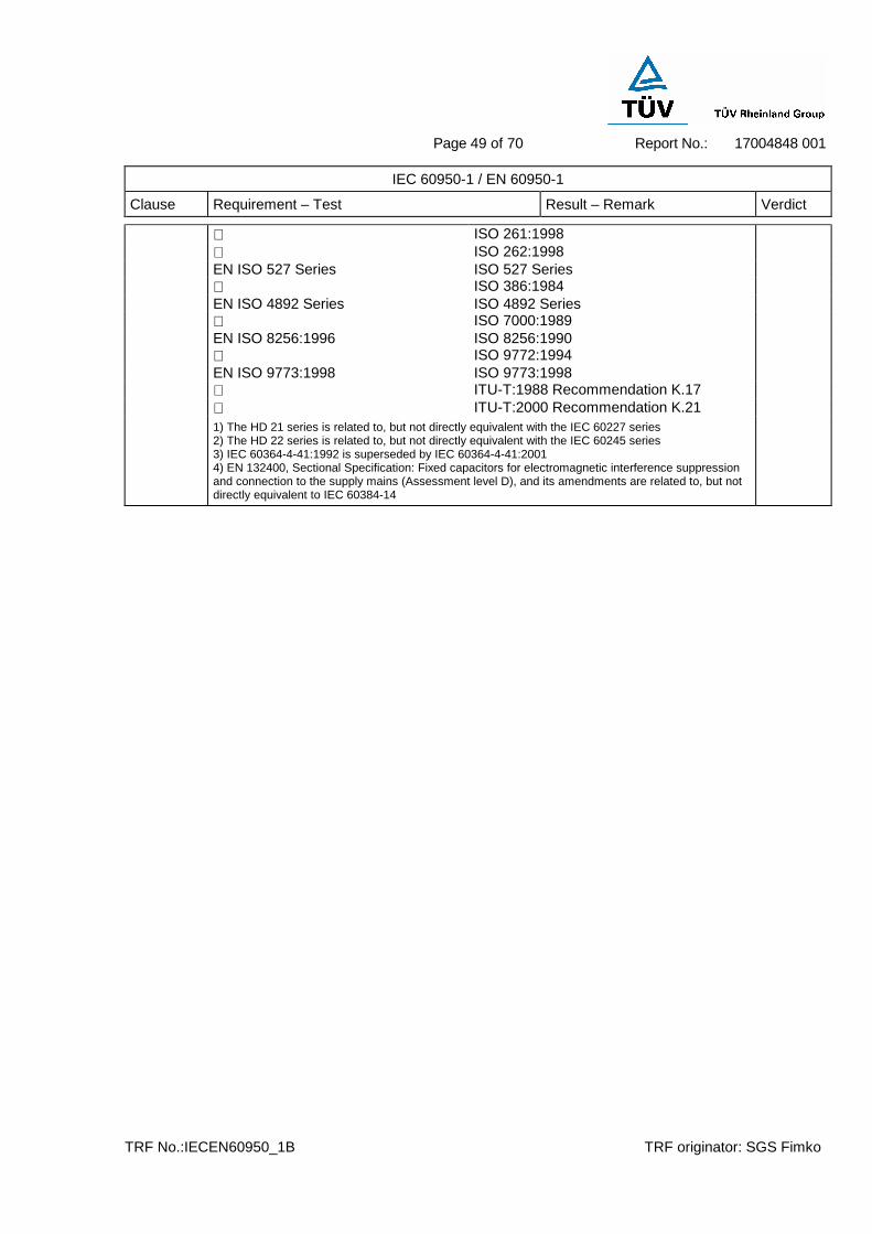
Page 49 of 70
Report No.: 17004848 001
TRF No.:IECEN60950_1B TRF originator: SGS Fimko
IEC 60950-1 / EN 60950-1
Clause Requirement – Test Result – Remark Verdict
ISO 261:1998 ISO 262:1998 EN ISO 527 Series ISO 527 Series ISO 386:1984 EN ISO 4892 Series ISO 4892 Series ISO 7000:1989 EN ISO 8256:1996 ISO 8256:1990 ISO 9772:1994 EN ISO 9773:1998 ISO 9773:1998 ITU-T:1988 Recommendation K.17 ITU-T:2000 Recommendation K.21
1) The HD 21 series is related to, but not directly equivalent with the IEC 60227 series 2) The HD 22 series is related to, but not directly equivalent with the IEC 60245 series 3) IEC 60364-4-41:1992 is superseded by IEC 60364-4-41:2001 4) EN 132400, Sectional Specification: Fixed capacitors for electromagnetic interference suppression and connection to the supply mains (Assessment level D), and its amendments are related to, but not directly equivalent to IEC 60384-14

Page 50 of 70
Report No.: 17004848 001
TRF No.:IECEN60950_1B TRF originator: SGS Fimko
1.5.1 TABLE: list of critical components
Object/part no. Manufacturer/ trademark
Type/model Technical data Standard Mark(s) of conformity 1.
Yue Qing Bei Er Jia Electronic Co. Ltd.
ST-A03-005 AC 2.5A, 250V EN 60320-1 VDE 40014833 Inlet
Rich Bay Co., Ltd.
R-201SN90 AC 2.5A, 250V EN 60320-1 VDE 40006957
Walter Electronic Co. Ltd.
PDU AC 250V, T3.15A EN 60127-1 EN 60127-3 VDE 40006776
Fuse (CF1) Shenzhen Lanson Electronics Co. Ltd.
Txxx250V AC 250V, T3.15A EN 60127-1 EN 60127-3
VDE 40010682
Xiamen Faratronic Co. Ltd.
MKP62 0.1µF, 275Vac, X2, 110°C IEC 60384-14 VDE 40000358
Carli Electronics Co., Ltd.
MPX 0.1µF, 275Vac, X2, 100°C
IEC 60384-14 VDE 40008520 X2-cap C1
Tenta Electric Industrial Co. Ltd.
MEX 0.1µF, 275Vac, X2, 100°C IEC 60384-14 VDE 119119
Success Electronics Co., Ltd.
SE 2200pF, 250Vac, Y1, 125°C IEC 60384-14 VDE 126596
JAY-NAY Co., Ltd.
JN 2200pF, 250Vac, Y1, 125°C
IEC 60384-14 VDE 40001831 Y1-cap C9
Hsuan Tai Electronic Co. Ltd.
CY 2200pF, 400Vac, Y1, 105°C IEC 60384-14 VDE 40008912
Everlight Electronics Co., Ltd.
EL817
Isolation Voltage=850V Peak Transient Over voltage = 6000V, CTI 175, internal Cr.=6.0mm, external Cr.=7.7mm, Dti=0.5mm
IEC 60747-5-2, IEC 60950 VDE 132249
Optocoupler (IC2)
VISHAY Semiconductor GmbH
TCET1114G
Isolation Voltage=850V Peak Transient Over voltage = 8000V, CTI 175, internal Cr.=4.3mm, external Cr.=8.1mm, Dti=0.7mm
IEC 60747-5-2, IEC 60950 VDE 115667

Page 51 of 70
Report No.: 17004848 001
TRF No.:IECEN60950_1B TRF originator: SGS Fimko
COSMO Electronics Corporation
KPC817
Isolation Voltage=850V Peak Transient Over voltage = 8000V, CTI 175, internal Cr.=5.3mm, external Cr.=8.0mm, Dti=0.5mm
IEC 60747-5-2, IEC 60950 VDE 101347
PCB Various Various V-0, 130°C UL 94 UL Recognized GE PLASTICS CHINA LTD
920/923 V-0, 130°C Thickness 2.4mm
UL 94 UL E161723
Enclosure TEIJIN CHEMICALS LTD
LN-1250G V-0, 105°C Thickness 2.4mm UL 94 UL E50075
Transformer (PT1)
Fuyuan Electronic Co.,Ltd
FYxxxyyyy PT Class B -- Test in appliance
Bobbin of PT1 and L1
CHANG CHUN PLASTICS CO LTD
T375J V-0, 150°C UL 94 UL E59481
FUQING YONGBIN ADHESIVE TAPE FACTORY
DEJZ3 130°C UL 510 UL E185774
Insulating Tape of PT1 and L1 JINGJIANG
YAHUA PRESSURE SENSITIVE GLUE CO LTD
PZ 130°C UL 510 UL E165111
Triple insulated wire of PT1
GREAT LEOFLON INDUSTRIAL CO LTD
TRW 155°C, 600V EN 60950 VDE 136581
Magnet wire of PT1 and L1
XIN LONG MAGNET WIRE CO LTD
UEW 130°C UL 1446 UL E171028
Line Filter (L1) Fuyuan Electronic Co.,Ltd
FY120L1 130°C -- Test in appliance
DONGGUAN QUANTAI ELECTRONICS CO LTD
T-2 125°C, 600V UL224 UL E227336
CHANGYUAN ELECTRONICS (SHENZHEN)
Changbao 102 125°C, 600V UL224 UL E180908
Shrinkable tubing
UNICHEM CO LTD
KUHS-225 125°C, 600V UL224 UL E157822
D1-D4 -- -- Min. 3A, 800V -- -- Ripple Cap. (C2)
Various -- Min.150µF, 400V, 105°C
-- --

Page 52 of 70
Report No.: 17004848 001
TRF No.:IECEN60950_1B TRF originator: SGS Fimko
Output cable Various Various 105°C, 300V, 18 AWG, VW-1
UL UL Recognized
1.6.2 TABLE: electrical data (in normal conditions) P
Fuse # Irated (A) U (V) P (W) I (mA) Ifuse (mA) Condition/status
FY1267500
-- -- 90V/50Hz 108.2 1887 1887
-- -- 90V/60Hz 105.6 1846 1846
CF1 2.5 100V/50Hz 107.6 1698 1698
CF1 2.5 100V/60Hz 105.0 1656 1656
CF1 2.5 240V/50Hz 107.2 947 947
CF1 2.5 240V/60Hz 110.6 912 912
-- -- 254.4V/50Hz
110.8 912 912
-- -- 254.4V/60Hz
110.8 862 862
12.6V/7500mA
FY2405000
-- -- 90V/50Hz 133.0 2420 2420
-- -- 90V/60Hz 132.8 2250 2250
CF1 2.5 100V/50Hz 132.7 2090 2090
CF1 2.5 100V/60Hz 131.8 1991 1991
CF1 2.5 240V/50Hz 129.2 1150 1150
CF1 2.5 240V/60Hz 131.1 1125 1125
-- -- 254.4V/50Hz
130.6 1056 1056
-- -- 254.4V/60Hz
133.0 1058 1058
24.0V/5000mA
FY4802500
-- -- 90V/50Hz 129.5 2300 2300
-- -- 90V/60Hz 128.5 2160 2160
CF1 2.5 100V/50Hz 127.8 2020 2020
CF1 2.5 100V/60Hz 128.1 1942 1942
CF1 2.5 240V/50Hz 127.8 1125 1125
CF1 2.5 240V/60Hz 127.2 1035 1035
48.0V/2500mA

Page 53 of 70
Report No.: 17004848 001
TRF No.:IECEN60950_1B TRF originator: SGS Fimko
-- -- 254.4V/50Hz
124.4 1027 1027
-- -- 254.4V/60Hz
126.7 1020 1020
FY5802000
-- -- 90V/50Hz 130.4 2340 2340
-- -- 90V/60Hz 129.1 2170 2170
CF1 2.5 100V/50Hz 127.6 2020 2020
CF1 2.5 100V/60Hz 128.1 1943 1943
CF1 2.5 240V/50Hz 126.7 1102 1102
CF1 2.5 240V/60Hz 129.0 1107 1107
-- -- 254.4V/50Hz
124.0 1042 1042
-- -- 254.4V/60Hz
127.9 1019 1019
58.0V/2000mA
FY0307500
-- -- 90V/50Hz 32.8 595 595
-- -- 90V/60Hz 30.6 578 578
CF1 2.5 100V/50Hz 34.2 544 544
CF1 2.5 100V/60Hz 31.1 524 524
CF1 2.5 240V/50Hz 36.3 323 323
CF1 2.5 240V/60Hz 34.7 295 295
-- -- 254.4V/50Hz
37.4 293 293
-- -- 254.4V/60Hz
35.2 291 291
3.0V/7500mA
FY1207500
-- -- 90V/50Hz 104.8 1195 1195
-- -- 90V/60Hz 104.7 1821 1821
CF1 2.5 100V/50Hz 104.1 1693 1693
CF1 2.5 100V/60Hz 103.9 1620 1620
CF1 2.5 240V/50Hz 106.1 923 923
CF1 2.5 240V/60Hz 104.1 892 892
-- -- 254.4V/50Hz
108.8 836 836
-- -- 254.4V/60Hz
106.3 885 885
12.0V/7500mA
Note(s):

Page 54 of 70
Report No.: 17004848 001
TRF No.:IECEN60950_1B TRF originator: SGS Fimko
2.1.1.5 TABLE: max. V, A, VA test P
Voltage (rated) (V)
Current (rated) (A)
Voltage (max.) (V)
Current (max.) (A)
VA (max.) (VA)
FY1267500
12.6 7.5 12.12 15.14 140.9
FY2405000
24 5.0 23.8 5.07 118.3
FY4802500
48 2.5 46.3 2.73 124.2
FY5802000
58 2.0 58.5 2.05 117.6
FY0307500
3 7.5 3.27 9.45 21.2
FY1207500
12 7.5 12.1 8.98 106.8
Note: the output energy less than 240VA.
2.1.1.7 TABLE: discharge test N/A
Condition τ calculated (s)
τ measured (s)
t u→ 0V (s)
Comments
Note(s):
2.2.2 TABLE: Hazardous voltage measurement P
max. Voltage Transformer Location
V peak V d.c.
Voltage Limitation Component
FY1267500
PT1 Pin 9 to pin 10 52.0 -
- 14.4 After D8
FY2405000
PT1 Pin 9 to pin 10 68.0 -
- 27.7 After D8
FY4802500
PT1 Pin 9 to pin 10 132.0 -
- 44.5 After D8
FY5802000

Page 55 of 70
Report No.: 17004848 001
TRF No.:IECEN60950_1B TRF originator: SGS Fimko
PT1 Pin 9 to pin 10 136.0 -
- 58.2 After D8
Note(s):
2.2.3 TABLE: SEL voltage measurement P
Location Voltage measured (V) Comments
FY1267500
Output (12.6V) 12.0 Normal load
Output (12.6V) 12.3 No load
Output (12.6V) 0 D8 short-circuit
FY2405000
Output (24V) 23.3 Normal load
Output (24V) 23.8 No load
Output (24V) 0 D8 short-circuit
FY4802500
Output (48V) 45.5 Normal load
Output (48V) 45.7 No load
Output (48V) 0 D8 short-circuit
FY5802000
Output (58V) 57.1 Normal load
Output (58V) 57.2 No load
Output (58V) 0 D8 short-circuit
Note (S):
2.4.2 TABLE: limited current circuit measurement P
Location Voltage (V)
Current (mA)
Freq. (kHz)
Limit (mA)
Comments
FY1267500
Y1-cap (C9) 6.2 3.1 56 39.2 A 2 kΩ resistor’s one terminal connected to secondary pin of C9, the other terminal of which was directly connected to neutral.
FY2405000
Y1-cap (C9) 6.2 3.1 56 39.2 A 2 kΩ resistor’s one terminal connected to secondary pin of C9, the other terminal of which was directly connected to neutral.

Page 56 of 70
Report No.: 17004848 001
TRF No.:IECEN60950_1B TRF originator: SGS Fimko
FY4802500
Y1-cap (C9) 6.2 3.1 56 39.2 A 2 kΩ resistor’s one terminal connected to secondary pin of C9, the other terminal of which was directly connected to neutral.
FY5802000
Y1-cap (C9) 5.6 2.8 56 39.2 A 2 kΩ resistor’s one terminal connected to secondary pin of C9, the other terminal of which was directly connected to neutral.
Note(s):
2.5 TABLE: limited power source measurement (Not required) N/A
Limits Measured Verdict
According to Table 2B (normal condition)
current (in A)
apparent power (in VA)
Note(s):
2.6.3.4 TABLE: ground continue test N/A
Location Resistance measured (mΩ) Comments
Note(s):
2.10.2 Table: working voltage measurement P
Location RMS voltage (V) Peak voltage (V) Comments
FY1267500
Pin 1-9 of PT1 256 472 The highest rms and Vpeak
Pin 1-10 of PT1 243 440
Pin 2-9 of PT1 - -
Pin 2-10 of PT1 - -
Pin 3-9 of PT1 208 344
Pin 3-10 of PT1 203 384
Pin 4-9 of PT1 252 408
Pin 4-10 of PT1 241 368
Pin 5-9 of PT1 239 360
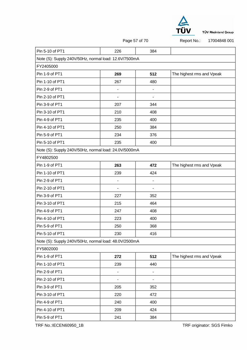
Page 57 of 70
Report No.: 17004848 001
TRF No.:IECEN60950_1B TRF originator: SGS Fimko
Pin 5-10 of PT1 226 384
Note (S): Supply 240V/50Hz, normal load: 12.6V/7500mA
FY2405000
Pin 1-9 of PT1 269 512 The highest rms and Vpeak
Pin 1-10 of PT1 267 480
Pin 2-9 of PT1 - -
Pin 2-10 of PT1 - -
Pin 3-9 of PT1 207 344
Pin 3-10 of PT1 210 408
Pin 4-9 of PT1 235 400
Pin 4-10 of PT1 250 384
Pin 5-9 of PT1 234 376
Pin 5-10 of PT1 235 400
Note (S): Supply 240V/50Hz, normal load: 24.0V/5000mA
FY4802500
Pin 1-9 of PT1 263 472 The highest rms and Vpeak
Pin 1-10 of PT1 239 424
Pin 2-9 of PT1 - -
Pin 2-10 of PT1 - -
Pin 3-9 of PT1 227 352
Pin 3-10 of PT1 215 464
Pin 4-9 of PT1 247 408
Pin 4-10 of PT1 223 400
Pin 5-9 of PT1 250 368
Pin 5-10 of PT1 230 416
Note (S): Supply 240V/50Hz, normal load: 48.0V/2500mA
FY5802000
Pin 1-9 of PT1 272 512 The highest rms and Vpeak
Pin 1-10 of PT1 239 440
Pin 2-9 of PT1 - -
Pin 2-10 of PT1 - -
Pin 3-9 of PT1 205 352
Pin 3-10 of PT1 220 472
Pin 4-9 of PT1 240 400
Pin 4-10 of PT1 209 424
Pin 5-9 of PT1 241 384

Page 58 of 70
Report No.: 17004848 001
TRF No.:IECEN60950_1B TRF originator: SGS Fimko
Pin 5-10 of PT1 227 440
Note (S): Supply 240V/50Hz, normal load: 58.0V/2000mA
2.10.3 and 2.10.4
TABLE: clearance and creepage distance measurements P
Clearance cl and creepage distance dcr at/of:
Up (V)
U r.m.s. (V)
Required cl (mm)
cl (mm)
Required dcr (mm)
dcr (mm)
On primary
L-N on PCB (F)* 420 240 1.5 6.1 2.5 6.1
Different polarity of fuse F1 (F) 420 240 1.5 3.0 2.5 3.0
Primary components to accessible part
Heat sink on primary (with 10N) to enclosure outside (R)*
420 240 4.0 8.6 5.0 8.6
Primary components to secondary components
Primary to secondary of Opto-coupler IC2 (R)
512 272 4.4 6.2 5.7 6.2
Primary to secondary of Y1-cap C9 (R)
512 272 4.4 6.2 5.7 6.2
Primary to secondary of transformer (R)
512 272 4.4 6.2 5.7 6.2
Secondary to core of transformer (R)
512 272 4.4 6.2 5.7 6.2
Note(s):
The construction check performed on the transformer of model FY5802000 which has the total Max. Secondary windings diameter considering the turns.
* F=functional insulation, R=reinforced insulation.
1) 3 layers insulation tape wrapped between primary soldering points, components and secondary heat sink as reinforced insulation
2) 3 layers insulation tape wrapped between secondary soldering points, components and primary heat sink as reinforced insulation
3) 3 layers insulation tape wrapped around external of transformer as reinforced insulation
4) Heat shrinkable tube used on fuse CF1 and C9 as functional insulation.
5) Triple insulated wire used for secondary winding of the transformer.
2.10.5 TABLE: distance through insulation measurements P
Distance through insulation di at/of: U r.m.s. (V)
Test voltage (V)
Required di (mm)
di (mm)
Enclosure (for reinforced insulation) 240 3000 0.4 2.4
Opto-coupler (for reinforced insulation) 240 3000 0.4 0.5

Page 59 of 70
Report No.: 17004848 001
TRF No.:IECEN60950_1B TRF originator: SGS Fimko
4.5.1 TABLE: maximum temperatures P
test voltage (V) ................................100x0.9=90V / 240x1,06=254V
tamb1 (°C) ..........................................--
tamb2 (°C) ..........................................--
maximum temperature T of part/at:: T (°C) allowed Tmax (°C)
FY1267500
90V/50Hz 254V/50Hz
Label up Label down Label up Label down
Ambient 25.0 25.0 25.0 25.0 --
AC inlet 56.2 55.3 43.2 46.0 70
X2-cap C1 body 69.9 68.1 53.6 55.2 100
L1 winding 84.9 84.4 62.7 64.0 130
PCB near D1 58.7 60.5 46.8 46.0 130
C2 body 86.7 85.6 65.3 66.8 105
Primary heatsink 74.9 72.5 63.5 65.7 --
Secondary heatsink 90.3 91.3 76.1 75.3 --
PT1 winding 87.0 86.5 83.1 86.8 120-
10=110
PT1 core 88.2 86.9 81.4 82.5 120-
10=110
Y1-cap C9 body 76.7 74.0 66.1 69.2 105
Opto-coupler IC2 body 74.8 77.3 64.3 61.1 100
PCB near R3 78.2 77.9 67.4 69.8 130
Output wire 68.0 68.8 58.5 55.2 --
Enclosure above PT1 (inside)
79.2 80.8 68.8 71.1 --
Enclosure above PT1 (outside)
66.4 64.6 57.3 55.2 95
Enclosure under PT1 (outside)
81.3 82.2 59.6 61.1 95
Enclosure under PT1 (inside)
71.0 72.5 66.0 67.6 --
FY2405000
90V/50Hz 254V/50Hz
Label up Label down Label up Label down
Ambient 25.0 25.0 25.0 25.0 --

Page 60 of 70
Report No.: 17004848 001
TRF No.:IECEN60950_1B TRF originator: SGS Fimko
AC inlet 67.7 64.5 42.3 46.0 70
X2-cap C1 body 84.2 82.8 57.7 56.4 100
L1 winding 86.2 88.8 69.4 67.1 130
PCB near D1 90.6 93.3 65.8 64.3 130
C2 body 86.6 86.6 60.6 59.3 105
Primary heatsink 84.7 82.8 63.3 60.5 --
Secondary heatsink 86.4 87.8 96.5 95.3 --
PT1 winding 79.6 81.0 86.9 84.5 120-
10=110
PT1 core 77.4 78.8 84.4 85.6 120-
10=110
Y1-cap C9 body 74.9 76.3 71.0 71.2 105
Opto-coupler IC2 body 76.8 75.1 65.9 68.1 100
PCB near R3 84.0 86.9 67.8 66.9 130
Output wire 65.1 63.0 79.4 77.5 --
Enclosure above PT1 (inside)
72.6 70.1 74.0 73.3 --
Enclosure above PT1 (outside)
64.9 64.5 65.9 65.4 95
Enclosure under PT1 (outside)
71.6 70.3 72.6 70.5 95
Enclosure under PT1 (inside)
75.1 78.3 74.6 75.4 --
FY4802500
90V/50Hz 254V/50Hz
Label up Label down Label up Label down
Ambient 25.0 25.0 25.0 25.0 --
AC inlet 51.8 50.6 42.2 46.0 70
X2-cap C1 body 63.6 65.4 53.4 54.2 100
L1 winding 76.9 77.0 63.4 60.5 130
PCB near D1 84.6 82.6 64.1 66.9 130
C2 body 86.1 88.3 67.2 68.1 105
Primary heatsink 74.0 75.9 63.4 65.3 --
Secondary heatsink 69.9 71.0 66.3 65.4 --
PT1 winding 85.6 85.6 84.4 86.8 120-
10=110
PT1 core 81.2 81.0 82.9 85.6 120-
10=110
Y1-cap C9 body 71.5 69.9 66.9 70.0 105

Page 61 of 70
Report No.: 17004848 001
TRF No.:IECEN60950_1B TRF originator: SGS Fimko
Opto-coupler IC2 body 68.7 71.2 63.8 64.3 100
PCB near R3 76.3 77.5 67.7 69.9 130
Output wire 49.5 46.0 44.7 43.0 --
Enclosure above PT1 (inside)
55.4 54.5 55.5 56.4 --
Enclosure above PT1 (outside)
53.8 56.4 53.6 50.6 95
Enclosure under PT1 (outside)
66.7 67.1 65.0 67.1 95
Enclosure under PT1 (inside)
73.0 75.4 73.0 72.8 --
FY5802000
90V/50Hz 254V/50Hz
Label up Label down Label up Label down
Ambient 25.0 25.0 25.0 25.0 --
AC inlet 65.5 62.3 54.0 59.3 70
X2-cap C1 body 80.1 80.8 41.9 41.1 100
L1 winding 55.2 52.8 52.3 54.2 130
PCB near D1 85.9 86.9 62.5 62.0 130
C2 body 85.5 85.6 48.3 48.9 105
Primary heatsink 67.6 64.6 63.9 63.1 --
Secondary heatsink 85.6 88.3 69.1 69.1 --
PT1 winding 81.6 81.1 83.0 85.5 120-
10=110
PT1 core 72.7 77.9 76.2 76.8 120-
10=110
Y1-cap C9 body 71.9 74.9 84.5 85.7 105
Opto-coupler IC2 body 79.4 82.2 69.2 66.9 100
PCB near R3 56.6 52.8 62.7 62.1 130
Output wire 63.9 62.3 64.2 64.5 --
Enclosure above PT1 (inside)
66.7 68.0 70.1 70.4 --
Enclosure above PT1 (outside)
60.8 64.9 62.4 60.7 95
Enclosure under PT1 (outside)
70.7 66.5 71.2 71.6 95
Enclosure under PT1 (inside)
71.2 73.7 76.4 75.5 --
4.5.2 TABLE: ball pressure test of thermoplastic parts P
allowed impression diameter (mm) .................. : ≤ 2 mm
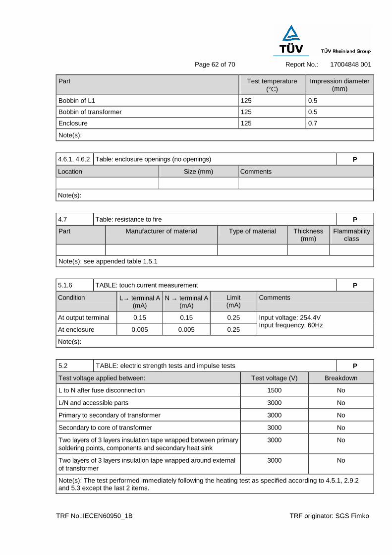
Page 62 of 70
Report No.: 17004848 001
TRF No.:IECEN60950_1B TRF originator: SGS Fimko
Part Test temperature (°C)
Impression diameter (mm)
Bobbin of L1 125 0.5
Bobbin of transformer 125 0.5
Enclosure 125 0.7
Note(s):
4.6.1, 4.6.2 Table: enclosure openings (no openings) P
Location Size (mm) Comments
Note(s):
4.7 Table: resistance to fire P
Part Manufacturer of material Type of material Thickness (mm)
Flammability class
Note(s): see appended table 1.5.1
5.1.6 TABLE: touch current measurement P
Condition L→ terminal A (mA)
N → terminal A (mA)
Limit (mA)
Comments
At output terminal 0.15 0.15 0.25
At enclosure 0.005 0.005 0.25
Input voltage: 254.4V Input frequency: 60Hz
Note(s):
5.2 TABLE: electric strength tests and impulse tests P
Test voltage applied between: Test voltage (V) Breakdown
L to N after fuse disconnection 1500 No
L/N and accessible parts 3000 No
Primary to secondary of transformer 3000 No
Secondary to core of transformer 3000 No
Two layers of 3 layers insulation tape wrapped between primary soldering points, components and secondary heat sink
3000 No
Two layers of 3 layers insulation tape wrapped around external of transformer
3000 No
Note(s): The test performed immediately following the heating test as specified according to 4.5.1, 2.9.2 and 5.3 except the last 2 items.

Page 63 of 70
Report No.: 17004848 001
TRF No.:IECEN60950_1B TRF originator: SGS Fimko
5.3 TABLE: fault condition tests P
ambient temperature (°C) ....................................25
model/type of power supply ................................--
manufacturer of power supply .............................--
rated markings of power supply ...........................--
component No.
fault
test voltage (V)
test time fuse No.
fuse current (A)
result
FY1267500
Output S-C 240V 1 minute CF1 0.950.18 The unit shutdown immediately, recoverable after the fault removed, no hazards observed.
Output O-L 240V 240 minutes
CF1 0.951.18 After the overload applied for 240 minutes, the unit shutdown at the max. output current 9.45A, the max. temperature of primary winding is 105.2°C. No hazards. Limit: (175-10)°C=165°C
D1 S-C 240V 1 second CF1 0.950 Fuse opened immediately, no hazards observed.
R3 S-C 240V 10 minutes CF1 0.950.95 The unit normally operation, no hazards observed.
C2 S-C 240V 10 minutes CF1 0.950.95 The unit normally operation, no hazards observed.
R2 S-C 240V 1 second CF1 0.950 Fuse opened immediately, no hazards observed.
D7 S-C 240V 10 minutes CF1 0.950.95 The unit normally operation, no hazards observed.
D8 S-C 240V 1 second CF1 0.950 Fuse opened immediately, no hazards observed.
Pin9 to Pin10 of PT1
S-C 240V 1 second CF1 0.950 Fuse opened immediately, R6, T1 damaged, no hazards observed.
IC2 Primary O-C 240V 10 minutes CF1 0.950 The unit shutdown immediately, recoverable after the fault removed, no hazards observed.
IC2 Secondary S-C 240V 1 second CF1 0.950 Fuse opened immediately, R6, T1 damaged, no hazards observed.

Page 64 of 70
Report No.: 17004848 001
TRF No.:IECEN60950_1B TRF originator: SGS Fimko
IC2 Primary S-C 240V 10 minutes CF1 0.950 The unit shutdown immediately, recoverable after the fault removed, no hazards observed.
IC2 Secondary O-C 240V 35 minutes CF1 0.951.98 After the short applied for 28 minutes, the unit shutdown, the max. temperature of primary winding is 115.6°C, Max. Output voltage is 12.5Vdc. R6, T1 damaged, CF1 opened, No hazards. Limit: (175-10)°C=165°C
Pin2-pin7 of IC1
S-C 240V 10 minutes CF1 0.950 The unit shutdown immediately, recoverable after the fault removed, no hazards observed.
T1 G-S S-C 240V 1 second CF1 0.950 Fuse opened immediately, no hazards observed.
T1 G-D S-C 240V 10 minutes CF1 0.950 The unit shutdown immediately, recoverable after the fault removed, no hazards observed.
T1 D-S S-C 240V 1 second CF1 0.950 Fuse opened immediately, no hazards observed.
Transformer O-L 240V 540 minutes
CF1 0.951.25 After the overload applied for 540 minutes, the unit shutdown at the max. output current 9.5A, the max. temperature of primary winding is 102.4°C. No hazards. Limit: (175-10)°C=165°C
FY2405000
Output S-C 240V 1 minute CF1 1.150.13 The unit shutdown immediately, recoverable after the fault removed, no hazards observed.
Output O-L 240V 240 minutes
CF1 1.151.21 After the overload applied for 240 minutes, the unit shutdown at the max. output current 5.2A, the max. temperature of primary winding is 101.5°C. No hazards. Limit: (175-10)°C=165°C
D1 S-C 240V 1 second CF1 1.150 Fuse opened immediately, no hazards observed.
R3 S-C 240V 10 minutes CF1 1.151.15 The unit normally operation, no hazards observed.
C2 S-C 240V 10 minutes CF1 1.151.15 The unit normally operation, no hazards observed.

Page 65 of 70
Report No.: 17004848 001
TRF No.:IECEN60950_1B TRF originator: SGS Fimko
R2 S-C 240V 1 second CF1 1.150 Fuse opened immediately, no hazards observed.
D7 S-C 240V 10 minutes CF1 1.151.15 The unit normally operation, no hazards observed.
C5 S-C 240V 1 second CF1 1.150 Fuse opened immediately, no hazards observed.
D8 S-C 240V 1 second CF1 1.150 Fuse opened immediately, no hazards observed.
Pin9 to Pin10 of PT1
S-C 240V 1 second CF1 1.150 Fuse opened immediately, R6, T1 damaged, no hazards observed.
IC2 Primary O-C 240V 10 minutes CF1 1.150 The unit shutdown immediately, recoverable after the fault removed, no hazards observed.
IC2 Secondary S-C 240V 1 second CF1 1.150 Fuse opened immediately, R6, T1 damaged, no hazards observed.
IC2 Primary S-C 240V 10 minutes CF1 1.150 The unit shutdown immediately, recoverable after the fault removed, no hazards observed.
IC2 Secondary O-C 240V 35 minutes CF1 1.152.04 After the short applied for 28 minutes, the unit shutdown, the max. temperature of primary winding is 122.6°C, Max. Output voltage is 23.8Vdc. R6, T1 damaged, CF1 opened, No hazards. Limit: (175-10)°C=165°C
Pin2-pin7 of IC1
S-C 240V 10 minutes CF1 1.150 The unit shutdown immediately, recoverable after the fault removed, no hazards observed.
T1 G-S S-C 240V 1 second CF1 1.150 Fuse opened immediately, no hazards observed.
T1 G-D S-C 240V 10 minutes CF1 1.150 The unit shutdown immediately, recoverable after the fault removed, no hazards observed.
T1 D-S S-C 240V 1 second CF1 1.150 Fuse opened immediately, no hazards observed.
Transformer O-L 240V 540 minutes
CF1 1.151.35 After the overload applied for 540 minutes, the unit shutdown at the max. output current 5.7A, the max. temperature of primary winding is 102.1°C. No hazards. Limit: (175-10)°C=165°C

Page 66 of 70
Report No.: 17004848 001
TRF No.:IECEN60950_1B TRF originator: SGS Fimko
FY4802500
Output S-C 240V 1 minute CF1 1.130.12 The unit shutdown immediately, recoverable after the fault removed, no hazards observed.
Output O-L 240V 240 minutes
CF1 1.131.18 After the overload applied for 240 minutes, the unit shutdown at the max. output current 2.7A, the max. temperature of primary winding is 101.5°C. No hazards. Limit: (175-10)°C=165°C
D1 S-C 240V 1 second CF1 1.130 Fuse opened immediately, no hazards observed.
R3 S-C 240V 10 minutes CF1 1.131.13 The unit normally operation, no hazards observed.
C2 S-C 240V 10 minutes CF1 1.131.13 The unit normally operation, no hazards observed.
R2 S-C 240V 1 second CF1 1.130 Fuse opened immediately, no hazards observed.
D7 S-C 240V 10 minutes CF1 1.131.13 The unit normally operation, no hazards observed.
C5 S-C 240V 1 second CF1 1.130 Fuse opened immediately, no hazards observed.
D8 S-C 240V 1 second CF1 1.130 Fuse opened immediately, no hazards observed.
Pin9 to Pin10 of PT1
S-C 240V 1 second CF1 1.130 Fuse opened immediately, R6, T1 damaged, no hazards observed.
IC2 Primary O-C 240V 10 minutes CF1 1.130 The unit shutdown immediately, recoverable after the fault removed, no hazards observed.
IC2 Secondary S-C 240V 1 second CF1 1.130 Fuse opened immediately, R6, T1 damaged, no hazards observed.
IC2 Primary S-C 240V 10 minutes CF1 1.130 The unit shutdown immediately, recoverable after the fault removed, no hazards observed.

Page 67 of 70
Report No.: 17004848 001
TRF No.:IECEN60950_1B TRF originator: SGS Fimko
IC2 Secondary O-C 240V 35 minutes CF1 1.132.05 After the shot applied for 28 minutes, the unit shutdown, the max. temperature of primary winding is 125.6°C, Max. Output voltage is 48.3Vdc. R6, T1 damaged, CF1 opened, No hazards. Limit: (175-10)°C=165°C
Pin2-pin7 of IC1
S-C 240V 10 minutes CF1 1.130 The unit shutdown immediately, recoverable after the fault removed, no hazards observed.
T1 G-S S-C 240V 1 second CF1 1.130 Fuse opened immediately, no hazards observed.
T1 G-D S-C 240V 10 minutes CF1 1.130 The unit shutdown immediately, recoverable after the fault removed, no hazards observed.
T1 D-S S-C 240V 1 second CF1 1.130 Fuse opened immediately, no hazards observed.
Transformer O-L 240V 600 minutes
CF1 1.131.25 After the overload applied for 600 minutes, the unit shutdown at the max. output current 3.2A, the max. temperature of primary winding is 115.4°C. No hazards. Limit: (175-10)°C=165°C
FY5802000
Output S-C 240V 1 minute CF1 1.100.09 The unit shutdown immediately, recoverable after the fault removed, no hazards observed.
Output O-L 240V 240 minutes
CF1 1.101.18 After the overload applied for 240 minutes, the unit shutdown at the max. output current 2.2A, the max. temperature of primary winding is 112.4°C. No hazards. Limit: (175-10)°C=165°C
D1 S-C 240V 1 second CF1 1.100 Fuse opened immediately, no hazards observed.
R3 S-C 240V 10 minutes CF1 1.101.10 The unit normally operation, no hazards observed.
C2 S-C 240V 10 minutes CF1 1.100.93 The unit normally operation, no hazards observed.
R2 S-C 240V 1 second CF1 1.100 Fuse opened immediately, no hazards observed.

Page 68 of 70
Report No.: 17004848 001
TRF No.:IECEN60950_1B TRF originator: SGS Fimko
D7 S-C 240V 10 minutes CF1 1.101.10 The unit normally operation, no hazards observed.
C5 S-C 240V 1 second CF1 1.100 Fuse opened immediately, no hazards observed.
D8 S-C 240V 1 second CF1 1.100 Fuse opened immediately, no hazards observed.
Pin9 to Pin10 of PT1
S-C 240V 1 second CF1 1.100 Fuse opened immediately, R6, T1 damaged, no hazards observed.
IC2 Primary O-C 240V 10 minutes CF1 1.100 The unit shutdown immediately, recoverable after the fault removed, no hazards observed.
IC2 Secondary S-C 240V 1 second CF1 1.100 Fuse opened immediately, R6, T1 damaged, no hazards observed.
IC2 Primary S-C 240V 10 minutes CF1 1.100 The unit shutdown immediately, recoverable after the fault removed, no hazards observed.
IC2 Secondary O-C 240V 35 minutes CF1 1.102.14 After the shot applied for 35 minutes, the unit shutdown, the max. temperature of primary winding is 122.4°C, Max. Output voltage is 58.2Vdc. R6, T1 damaged, CF1 opened, No hazards. Limit: (175-10)°C=165°C
Pin2-pin7 of IC1
S-C 240V 10 minutes CF1 1.100 The unit shutdown immediately, recoverable after the fault removed, no hazards observed.
T1 G-S S-C 240V 1 second CF1 1.100 Fuse opened immediately, no hazards observed.
T1 G-D S-C 240V 10 minutes CF1 1.100 The unit shutdown immediately, recoverable after the fault removed, no hazards observed.
T1 D-S S-C 240V 1 second CF1 1.100 Fuse opened immediately, no hazards observed.
Transformer O-L 240V 540 minutes
CF1 0.951.04 After the overload applied for 540 minutes, the unit shutdown at the max. output current 2.8A, the max. temperature of primary winding is 138.8°C. No hazards. Limit: (175-10)°C=165°C
Note (S): S-C=short-circuited, O-C=open-circuited, O-L=overload. The unit passed 3000V hi-pot test between primary and accessible parts after the above single fault condition performed.

Page 69 of 70
Report No.: 17004848 001
TRF No.:IECEN60950_1B TRF originator: SGS Fimko
C.2 Safety isolation transformer P
Construction details:
Transformer part name: PT1
Manufacturer: See appended table 1.5.1
Type: See appended table 1.5.1
Note: the construction check performed on the transformer of model FY5802000 which has the total Max. Secondary windings diameter considering the turns.
Recurring peak voltage 512V
Required clearance for reinforced insulation (from table 2H and 2J)
4.4mm
Effective voltage rms 272V
Required creepage distance for reinforced insulation (from table 2L)
5.6mm
Measured min. creepage distance
Location inside (mm) outside (mm)
Primary-secondary Triple insulated wires used
6.2
Primary-core Core considered as primary
Core considered as primary
Secondary-core Triple insulated wires used
6.2
Primary-primary % %
Measured min. clearances
Location inside (mm) outside (mm)
Primary-secondary Triple insulated wires used
6.2
Primary-core Core considered as primary
Core considered as primary
Secondary-core Triple insulated wires used
6.2
Primary-primary % %
Construction:

Page 70 of 70
Report No.: 17004848 001
TRF No.:IECEN60950_1B TRF originator: SGS Fimko
Concentric windings on type T375J bobbin ( Phenolic, thickness 0.8mm, V-0), three layers insulation tape wrapped around external of transformer as reinforced insulation. Triple insulated wires used as secondary winding. Insulating tape used to separate primary windings and secondary triple insulated wires in crossing section. The lead pins soldered to primary windings were directly moulded in bobbin and the lead pins of secondary windings were directly moulded in PCB.
Pin numbers
Prim. 13, 45
Sec. 910
Bobbin
Material CHANG CHUN PLASTIC CO LTD, type T375J, V-0, 150°C.
Thickness 0.8mm
Electric strength test
With 3000 V a.c. after humidity treatment
Result Pass