test report - texas instruments...
TRANSCRIPT
www.nemko.com Nemko Canada Inc., a testing laboratory, is
accredited by the Standards Council of
Canada. The tests included in this report
are within the scope of this accreditation
ETSI EN 300 328 1.8.1 DTS; Date: May 2013
SCC AccreditedLAB
LABAccrédité CCN
TM
ONE WORLD OUR APPROVAL
Test report
264561-4TRFWL
Date of issue: November 20, 2014
Applicant:
Texas Instruments Inc.
Product:
CC3100 Booster-pack
Model:
CC3100MODR11MAMOB
Specifications:
ETSI EN 300 328 V1.8.1 (2012-06) Electromagnetic compatibility and Radio spectrum Matters (ERM);
Wideband transmission systems; Data transmission equipment
operating in the 2.5 GHz ISM band and using wide band modulation
techniques; Harmonized EN covering essential requirements under
article 3.2 of the R&TTE directive

Report reference ID: 264561-4TRFWL Page 2 of 29
Test location
Company name: Nemko Canada Inc.
Address: 303 River Road
City: Ottawa
Province: Ontario
Postal code: K1V 1H2
Country: Canada
Telephone: +1 613 737 9680
Facsimile: +1 613 737 9691
Toll free: +1 800 563 6336
Website: www.nemko.com
Tested by: Kevin Rose, Wireless/EMC Specialist
Reviewed by: Andrey Adelberg, Senior Wireless/EMC Specialist Date: November 20, 2014
Signature:
Limits of responsibility
Note that the results contained in this report relate only to the items tested and were obtained in the period between the date of initial receipt of samples
and the date of issue of the report.
This test report has been completed in accordance with the requirements of ISO/IEC 17025. All results contain in this report are within Nemko Canada’s
ISO/IEC 17025 accreditation.
Copyright notification
Nemko Canada Inc. authorizes the applicant to reproduce this report provided it is reproduced in its entirety and for use by the company’s employees only.
Any use which a third party makes of this report, or any reliance on or decisions to be made based on it, are the responsibility of such third parties.
Nemko Canada Inc. accepts no responsibility for damages, if any, suffered by any third party as a result of decisions made or actions based on this report.
© Nemko Canada Inc.
Report reference ID: 264561-4TRFWL Page 3 of 29
Table of contents
Table of contents .......................................................................................................................................................................................................... 3 Section 1. Report summary ................................................................................................................................................................................. 4
1.1 Applicant and manufacturer .................................................................................................................................................................................... 4 1.2 Test specifications .................................................................................................................................................................................................... 4 1.3 Statement of compliance ......................................................................................................................................................................................... 4 1.4 Exclusions ................................................................................................................................................................................................................. 4 1.5 Test report revision history ...................................................................................................................................................................................... 4
Section 2. Summary of test results ....................................................................................................................................................................... 5 2.1 ETSI EN 300 328 V1.8.1 (2012-06) test results .......................................................................................................................................................... 5
Section 3. Equipment under test (EUT) details ..................................................................................................................................................... 6 3.1 Sample information .................................................................................................................................................................................................. 6 3.2 EUT information ....................................................................................................................................................................................................... 6 3.3 Technical information .............................................................................................................................................................................................. 6 3.4 Product description and theory of operation ........................................................................................................................................................... 6 3.5 EUT exercise details .................................................................................................................................................................................................. 6 3.6 EUT setup diagram ................................................................................................................................................................................................... 6
Section 4. Engineering considerations .................................................................................................................................................................. 7 4.1 Modifications incorporated in the EUT..................................................................................................................................................................... 7 4.2 Technical judgment .................................................................................................................................................................................................. 7 4.3 Deviations from laboratory tests procedures ........................................................................................................................................................... 7
Section 5. Test conditions .................................................................................................................................................................................... 8 5.1 Atmospheric conditions ........................................................................................................................................................................................... 8 5.2 Power supply range .................................................................................................................................................................................................. 8 5.3 Regulated lead-acid battery power sources ............................................................................................................................................................. 8 5.4 Other power sources ................................................................................................................................................................................................ 8
Section 6. Measurement uncertainty ................................................................................................................................................................... 9 6.1 Uncertainty of measurement ................................................................................................................................................................................... 9
Section 7. Test equipment ................................................................................................................................................................................. 10 7.1 Test equipment list ................................................................................................................................................................................................. 10
Section 8. Testing data ...................................................................................................................................................................................... 11 8.1 EN 300 328 Clause 4.3.2.1 RF output power .......................................................................................................................................................... 11 8.2 EN 300 328 Clause 4.3.2.2 Power Spectral Density ................................................................................................................................................ 14 8.3 EN 300 328 Clause 4.3.2.5 Adaptivity (adaptive equipment using modulations other than FHSS) ......................................................................... 15 8.4 EN 300 328 Clause 4.3.2.6 Occupied Channel Bandwidth ...................................................................................................................................... 19 8.5 EN 300 328 Clause 4.3.2.7 Transmitter unwanted emissions in the out-of-band domain ...................................................................................... 21 8.6 EN 300 328 Clause 4.3.2.8 Transmitter unwanted emissions in the spurious domain ........................................................................................... 23 8.7 EN 300 328 Clause 4.3.2.9 Receiver spurious emissions......................................................................................................................................... 26 8.8 Clause 4.3.2.10 Receiver blocking .......................................................................................................................................................................... 28
Section 9. Block diagrams of test set-ups ........................................................................................................................................................... 29 9.1 Radiated emissions set-up ...................................................................................................................................................................................... 29

Section 1 Report summary
Report reference ID: 264561-4TRFWL Page 4 of 29
Section 1. Report summary
1.1 Applicant and manufacturer
Company name Texas Instruments Inc.
Address 12500 TI Boulevard
City Dallas
Province/State Texas
Postal/Zip code 75243
Country USA
1.2 Test specifications
ETSI EN 300 328 V1.8.1 (2012-06) Electromagnetic compatibility and Radio spectrum Matters (ERM); Wideband transmission systems; Data transmission equipment operating in the 2.5 GHz ISM band and using wide band modulation techniques; Harmonized EN covering essential requirements under article 3.2 of the R&TTE directive
1.3 Statement of compliance
In the configuration tested, the EUT was found compliant.
Testing was completed against all relevant requirements of the test standard. Results obtained indicate that the product under test complies in full with the requirements tested. The test results relate only to the items tested.
See “Summary of test results” for full details.
1.4 Exclusions
None
1.5 Test report revision history
Revision # Details of changes made to test report
TRF Original report issued

Section 2: Summary of test results
Report reference ID: 264561-4TRFWL Page 5 of 29
Section 2. Summary of test results
2.1 ETSI EN 300 328 V1.8.1 (2012-06) test results
Clause Test description Verdict
4.3.1 Technical requirements for Frequency Hopping equipment Not applicable1 4.3.2 Technical requirements for other types of Wide Band modulation Applicable 4.3.2.1 RF ouput power Pass 4.3.2.2 Power Spectral Density Pass 4.3.2.3 Duty Cycle, Tx-sequence, Tx-gap Not applicable2 4.3.2.4 Medium Utilisation (MU) factor Not applicable2 4.3.2.5 Adaptivity (adaptive equipment using modulations other than FHSS) Pass 4.3.2.6 Occupied Channel Bandwidth Pass 4.3.2.7 Transmitter unwanted emissions in the out-of-band domain Pass 4.3.2.8 Transmitter unwanted emissions in the spurious domain Pass 4.3.2.9 Receiver spurious emissions Not applicable4 4.3.2.10 Receiver Blocking Not applicable4
Notes: 1The EUT is not frequency hopping device. 2This requirement does not apply for equipment with a maximum declared RF Output power level of less than 10 dBm e.i.r.p. or for equipment when
operating in a mode where the RF Output power is less than 10 dBm e.i.r.p. 3This requirement does not apply to non-adaptive equipment or adaptive equipment operating in a non-adaptive mode providing the equipment
complies with the requirements and/or restrictions applicable to non-adaptive equipment 4This EUT is not a receiver.
Section 3: Equipment under test (EUT) details
Report reference ID: 264561-4TRFWL Page 6 of 29
Section 3. Equipment under test (EUT) details
3.1 Sample information
Receipt date July 21, 2014
Nemko sample ID number 4 and 5
3.2 EUT information
Product name CC3100 Booster-pack
Model CC3100MODR11MAMOB
Serial number N/A
3.3 Technical information
Operating band 2400–2483.5 MHz
Operating frequency 2412–2462 MHz
Modulation type 802.11b/g/n
Power requirements 230 VAC, 50 Hz via Laptop power adapter connected with USB cord to EUT
Antenna information Taiyo Yuden 2.4 GHz Multilayer RadiEdge Antenna, MN: AH 316M245001, Peak Gain: 1.9 dBi
The EUT uses a unique antenna coupling/ non-detachable antenna to the intentional radiator.
3.4 Product description and theory of operation
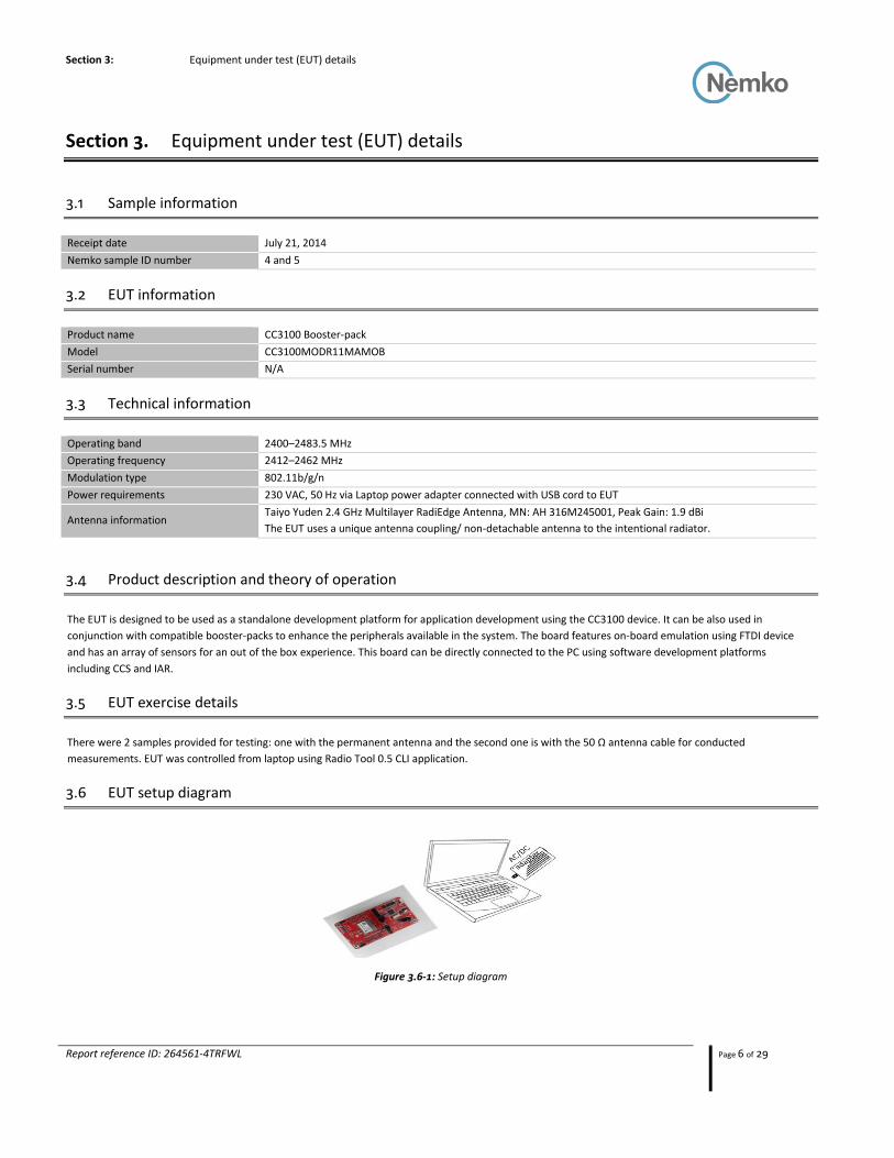
The EUT is designed to be used as a standalone development platform for application development using the CC3100 device. It can be also used in
conjunction with compatible booster-packs to enhance the peripherals available in the system. The board features on-board emulation using FTDI device
and has an array of sensors for an out of the box experience. This board can be directly connected to the PC using software development platforms
including CCS and IAR.
3.5 EUT exercise details
There were 2 samples provided for testing: one with the permanent antenna and the second one is with the 50 Ω antenna cable for conducted
measurements. EUT was controlled from laptop using Radio Tool 0.5 CLI application.
3.6 EUT setup diagram
Figure 3.6-1: Setup diagram
Section 4: Engineering consideration
Report reference ID: 264561-4TRFWL Page 7 of 29
Section 4. Engineering considerations
4.1 Modifications incorporated in the EUT
There were no modifications performed to the EUT during this assessment.
4.2 Technical judgment
As per manufacture request the CC3200MODR1M2AMOB model was considered as a representative sample and all the tests were performed on it. CC3100MODR11MAMOB is a depopulated version of the CC3200MODR1M2AMOB and therefor was deemed compliant.
4.3 Deviations from laboratory tests procedures
No deviations were made from laboratory procedures.
Section 6: Measurement uncertainty
Report reference ID: 264561-4TRFWL Page 8 of 29
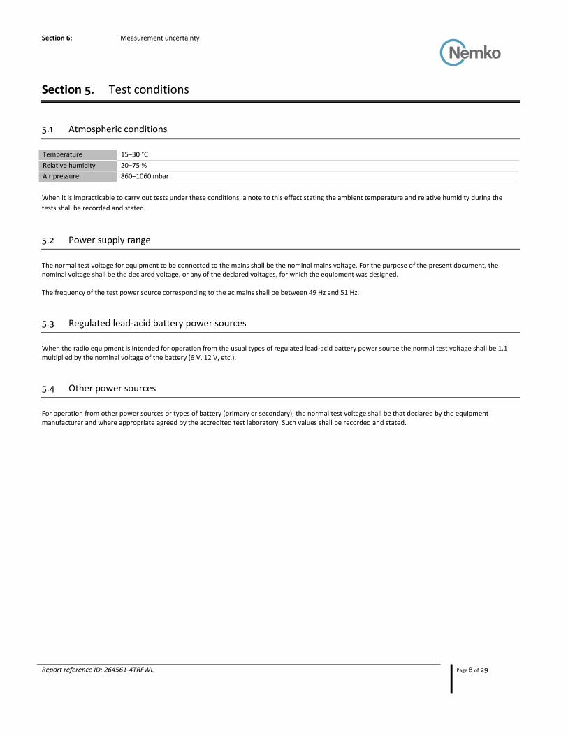
Section 5. Test conditions
5.1 Atmospheric conditions
Temperature 15–30 °C
Relative humidity 20–75 %
Air pressure 860–1060 mbar
When it is impracticable to carry out tests under these conditions, a note to this effect stating the ambient temperature and relative humidity during the
tests shall be recorded and stated.
5.2 Power supply range
The normal test voltage for equipment to be connected to the mains shall be the nominal mains voltage. For the purpose of the present document, the nominal voltage shall be the declared voltage, or any of the declared voltages, for which the equipment was designed. The frequency of the test power source corresponding to the ac mains shall be between 49 Hz and 51 Hz.
5.3 Regulated lead-acid battery power sources
When the radio equipment is intended for operation from the usual types of regulated lead-acid battery power source the normal test voltage shall be 1.1 multiplied by the nominal voltage of the battery (6 V, 12 V, etc.).
5.4 Other power sources
For operation from other power sources or types of battery (primary or secondary), the normal test voltage shall be that declared by the equipment manufacturer and where appropriate agreed by the accredited test laboratory. Such values shall be recorded and stated.
Section 6: Measurement uncertainty
Report reference ID: 264561-4TRFWL Page 9 of 29
Section 6. Measurement uncertainty
6.1 Uncertainty of measurement
Nemko Canada Inc. has calculated measurement uncertainty and is documented in EMC/MUC/001 “Uncertainty in EMC measurements.” Measurement uncertainty was calculated using the methods described in CISPR 16-4 Specification for radio disturbance and immunity measuring apparatus and methods – Part 4: Uncertainty in EMC measurements; as well as described in UKAS LAB34: The expression of Uncertainty in EMC Testing. Measurement uncertainty calculations assume a coverage factor of K=2 with 95% certainty.
Section 7: Test equipment
Report reference ID: 264561-4TRFWL Page 10 of 29
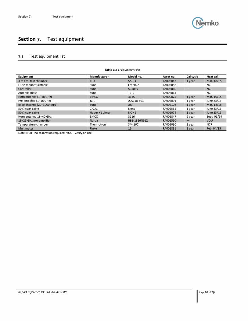
Section 7. Test equipment
7.1 Test equipment list
Table 7.1-1: Equipment list
Equipment Manufacturer Model no. Asset no. Cal cycle Next cal.
3 m EMI test chamber TDK SAC-3 FA002047 1 year Mar. 18/15 Flush mount turntable Sunol FM2022 FA002082 — NCR Controller Sunol SC104V FA002060 — NCR Antenna mast Sunol TLT2 FA002061 — NCR Horn antenna (1–18 GHz) EMCO 3115 FA000825 1 year Mar. 10/15 Pre-amplifier (1–18 GHz) JCA JCA118-503 FA002091 1 year June 23/15 Bilog antenna (20–3000 MHz) Sunol JB3 FA002108 1 year Mar. 12/15 50 Ω coax cable C.C.A. None FA002555 1 year June 23/15 50 Ω coax cable Huber + Suhner NONE FA002074 1 year June 23/15 Horn antenna 18–40 GHz EMCO 3116 FA001847 2 year Sept. 06/14 18–26 GHz pre-amplifier Narda BBS-1826N612 FA001550 — VOU Temperature chamber Thermotron SM-16C FA001030 1 year NCR Multimeter Fluke 16 FA001831 1 year Feb. 04/15
Note: NCR - no calibration required, VOU - verify on use
Section 8 Testing data
Test name Clause 4.3.2.1 RF output power Specification ETSI EN 300 328 V1.8.1 (2012)
Report reference ID: 264561-4TRFWL Page 11 of 29
Section 8. Testing data
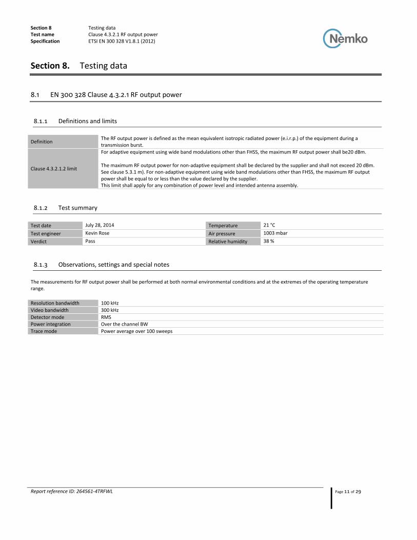
8.1 EN 300 328 Clause 4.3.2.1 RF output power
8.1.1 Definitions and limits
Definition The RF output power is defined as the mean equivalent isotropic radiated power (e.i.r.p.) of the equipment during a transmission burst.
Clause 4.3.2.1.2 limit
For adaptive equipment using wide band modulations other than FHSS, the maximum RF output power shall be20 dBm. The maximum RF output power for non-adaptive equipment shall be declared by the supplier and shall not exceed 20 dBm. See clause 5.3.1 m). For non-adaptive equipment using wide band modulations other than FHSS, the maximum RF output power shall be equal to or less than the value declared by the supplier. This limit shall apply for any combination of power level and intended antenna assembly.
8.1.2 Test summary
Test date July 28, 2014 Temperature 21 °C
Test engineer Kevin Rose Air pressure 1003 mbar
Verdict Pass Relative humidity 38 %
8.1.3 Observations, settings and special notes
The measurements for RF output power shall be performed at both normal environmental conditions and at the extremes of the operating temperature range.
Resolution bandwidth 100 kHz
Video bandwidth 300 kHz
Detector mode RMS
Power integration Over the channel BW
Trace mode Power average over 100 sweeps

Section 8 Testing data
Test name Clause 4.3.2.1 RF output power Specification ETSI EN 300 328 V1.8.1 (2012)
Report reference ID: 264561-4TRFWL Page 12 of 29
8.1.4 Test data
Table 8.1-1: Output power measurements results 23 degrees 230 Vac
Modulation Frequency,
MHz Conducted output power, dBm Antenna gain, dBi
EIRP, dBm
EIRP limit, dBm
EIRP margin, dB
802.11b 2412 12.18 1.9 14.08 20 5.92 2437 14.14 1.9 16.04 20 3.96 2472 12.43 1.9 14.33 20 5.67
802.11g 2412 12.75 1.9 14.65 20 5.35 2437 14.64 1.9 16.54 20 3.46 2472 12.65 1.9 14.55 20 5.45
802.11n 2412 11.43 1.9 13.33 20 6.67 2437 14.20 1.9 16.1 20 3.90 2472 12.66 1.9 14.56 20 5.44
Table 8.1-2: Output power measurements results -20 degrees 90 Vac
Modulation Frequency,
MHz Conducted output power, dBm Antenna gain, dBi
EIRP, dBm
EIRP limit, dBm
EIRP margin, dB
802.11b 2412 13.19 1.9 15.09 20 4.91 2437 14.81 1.9 16.71 20 3.29 2472 12.84 1.9 14.74 20 5.26
802.11g 2412 13.11 1.9 15.01 20 4.99 2437 14.87 1.9 16.77 20 3.23 2472 12.98 1.9 14.88 20 5.12
802.11n 2412 11.87 1.9 13.77 20 6.23 2437 14.72 1.9 16.62 20 3.38 2472 12.83 1.9 14.73 20 5.27
Table 8.1-3: Output power measurements results -20 degrees 264 Vac
Modulation Frequency,
MHz Conducted output power, dBm Antenna gain, dBi
EIRP, dBm
EIRP limit, dBm
EIRP margin, dB
802.11b 2412 13.21 1.9 15.11 20 4.89 2437 14.75 1.9 16.65 20 3.35 2472 12.83 1.9 14.73 20 5.27
802.11g 2412 13.14 1.9 15.04 20 4.96 2437 14.79 1.9 16.69 20 3.31 2472 12.93 1.9 14.83 20 5.17
802.11n 2412 11.91 1.9 13.81 20 6.19 2437 14.75 1.9 16.65 20 3.35 2472 12.81 1.9 14.71 20 5.29
Table 8.1-4: Output power measurements results 70 degrees 90 Vac
Modulation Frequency,
MHz Conducted output power, dBm Antenna gain, dBi
EIRP, dBm
EIRP limit, dBm
EIRP margin, dB
802.11b 2412 11.14 1.9 13.04 20 6.96 2437 12.88 1.9 14.78 20 5.22 2472 10.58 1.9 12.48 20 7.52
802.11g 2412 12.33 1.9 14.23 20 5.77 2437 14.13 1.9 16.03 20 3.97 2472 12.65 1.9 14.55 20 5.45
802.11n 2412 11.71 1.9 13.61 20 6.39 2437 14.42 1.9 16.32 20 3.68 2472 12.66 1.9 14.56 20 5.44

Section 8 Testing data
Test name Clause 4.3.2.1 RF output power Specification ETSI EN 300 328 V1.8.1 (2012)
Report reference ID: 264561-4TRFWL Page 13 of 29
8.1.4 Test data
Table 8.1-5: Output power measurements results 70 degrees 264 Vac
Modulation Frequency,
MHz Conducted output power, dBm Antenna gain, dBi
EIRP, dBm
EIRP limit, dBm
EIRP margin, dB
802.11b 2412 11.07 1.9 12.97 20 7.03 2437 12.72 1.9 14.62 20 5.38 2472 10.61 1.9 12.51 20 7.49
802.11g 2412 12.19 1.9 14.09 20 5.91 2437 14.18 1.9 16.08 20 3.92 2472 12.53 1.9 14.43 20 5.57
802.11n 2412 11.82 1.9 13.72 20 6.28 2437 14.36 1.9 16.26 20 3.74 2472 12.52 1.9 14.42 20 5.58
Section 8 Testing data
Test name Clause 4.3.2.2 Power Spectral Density Specification ETSI EN 300 328 V1.8.1 (2012)
Report reference ID: 264561-4TRFWL Page 14 of 29
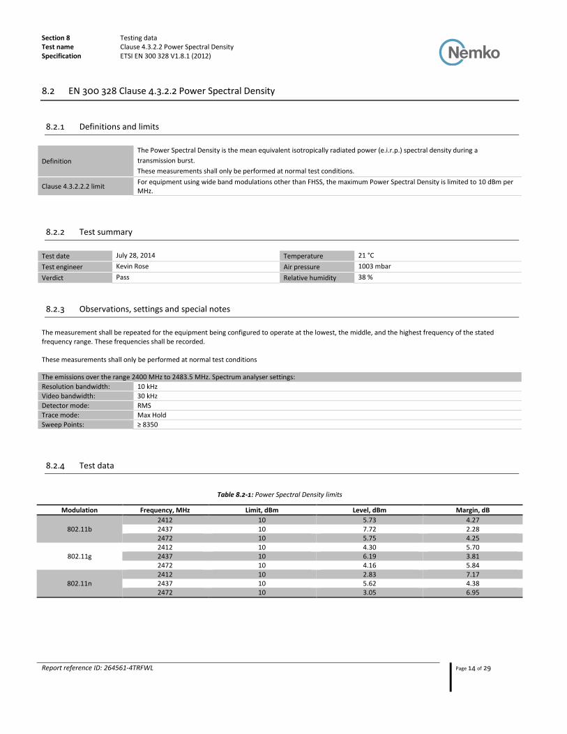
8.2 EN 300 328 Clause 4.3.2.2 Power Spectral Density
8.2.1 Definitions and limits
Definition
The Power Spectral Density is the mean equivalent isotropically radiated power (e.i.r.p.) spectral density during a
transmission burst.
These measurements shall only be performed at normal test conditions.
Clause 4.3.2.2.2 limit For equipment using wide band modulations other than FHSS, the maximum Power Spectral Density is limited to 10 dBm per MHz.
8.2.2 Test summary
Test date July 28, 2014 Temperature 21 °C
Test engineer Kevin Rose Air pressure 1003 mbar
Verdict Pass Relative humidity 38 %
8.2.3 Observations, settings and special notes
The measurement shall be repeated for the equipment being configured to operate at the lowest, the middle, and the highest frequency of the stated frequency range. These frequencies shall be recorded. These measurements shall only be performed at normal test conditions
The emissions over the range 2400 MHz to 2483.5 MHz. Spectrum analyser settings:
Resolution bandwidth: 10 kHz
Video bandwidth: 30 kHz
Detector mode: RMS
Trace mode: Max Hold
Sweep Points: ≥ 8350
8.2.4 Test data
Table 8.2-1: Power Spectral Density limits
Modulation Frequency, MHz Limit, dBm Level, dBm Margin, dB
802.11b 2412 10 5.73 4.27 2437 10 7.72 2.28 2472 10 5.75 4.25
802.11g 2412 10 4.30 5.70 2437 10 6.19 3.81 2472 10 4.16 5.84
802.11n 2412 10 2.83 7.17 2437 10 5.62 4.38 2472 10 3.05 6.95

Section 8 Testing data
Test name EN 300 328, Clause 4.3.2.5 Adaptivity (adaptive equipment using modulations other than FHSS)
Specification ETSI EN 300 328 V1.8.1 (2012)
Report reference ID: 264561-4TRFWL Page 15 of 29
8.3 EN 300 328 Clause 4.3.2.5 Adaptivity (adaptive equipment using modulations other than FHSS)
8.3.1 Definitions and limits
Definition: Non-LBT based Detect and Avoid is a mechanism for equipment using wide band modulations other than FHSS and by which a
given channel is made 'unavailable' because interference was reported after the transmission in that channel.
Clause 4.3.2.5.1.2 limit
1) During normal operation, the equipment shall evaluate the presence of a signal on its current operating channel. If it is determined that a signal is present with a level above the detection threshold defined in 4). the channel shall be marked as 'unavailable'. 2) The channel shall remain unavailable for a minimum time equal to 1 s after which the channel may be considered again as an 'available' channel. 3) The total time during which equipment has transmissions on a given channel without re-evaluating the availability of that channel, is defined as the Channel Occupancy Time. 4) The Channel Occupancy Time shall be less than 40 ms. Each such transmission sequence shall be followed with an Idle Period (no transmissions) of minimum 5 % of the Channel Occupancy Time with a minimum of 100 μs. After this, the procedure as in step 1 needs to be repeated. 5) The detection threshold shall be proportional to the transmit power of the transmitter: for a 20 dBm e.i.r.p. transmitter the detection threshold level (TL) shall be equal or lower than -70 dBm/MHz at the input to the receiver (assuming a 0 dBi receive antenna). For power levels below 20 dBm e.i.r.p., the detection threshold level may be relaxed to TL = -70 dBm/MHz + 20 - Pout e.i.r.p. (Pout in dBm).
8.3.2 Test summary
Test date: January 17, 2014 Temperature: 22 °C
Test engineer: David Light Air pressure: 1003 mbar
Verdict: Pass Relative humidity: 26 %
8.3.3 Observations, settings and special notes
Note: Test was performed on January 17 2014 test report 2014_251898_EU_300328
Section 8 Testing data
Test name EN 300 328, Clause 4.3.2.5 Adaptivity (adaptive equipment using modulations other than FHSS)
Specification ETSI EN 300 328 V1.8.1 (2012)
Report reference ID: 264561-4TRFWL Page 16 of 29
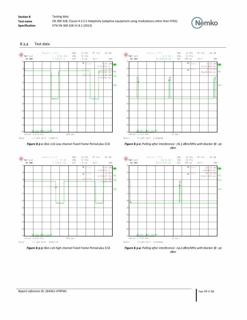
8.3.4 Test data
Figure 8.3-1: 802.11b Low channel Fixed Frame Period plus CCA Figure 8.3-2: Polling after interference -76.3 dBm/MHz with blocker @ -30 dBm
Figure 8.3-3: 802.11b high channel Fixed Frame Period plus CCA Figure 8.3-4: Polling after interference -74.0 dBm/MHz with blocker @ -30 dBm

Section 8 Testing data
Test name EN 300 328, Clause 4.3.2.5 Adaptivity (adaptive equipment using modulations other than FHSS)
Specification ETSI EN 300 328 V1.8.1 (2012)
Report reference ID: 264561-4TRFWL Page 17 of 29
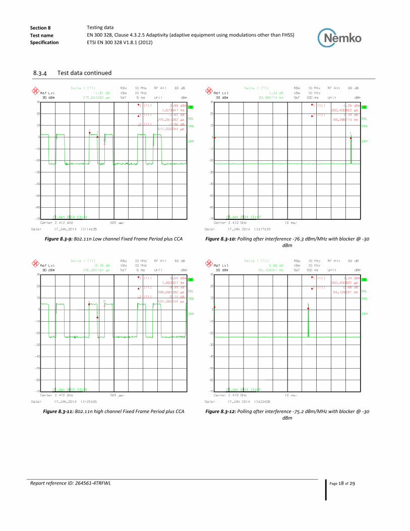
8.3.4 Test data continued
Figure 8.3-5: 802.11g Low channel Fixed Frame Period plus CCA Figure 8.3-6: Polling after interference -77.1 dBm/MHz with blocker @ -30 dBm
Figure 8.3-7: 802.11g high channel Fixed Frame Period plus CCA Figure 8.3-8: Polling after interference -75.1 dBm/MHz with blocker @ -30 dBm
Section 8 Testing data
Test name EN 300 328, Clause 4.3.2.5 Adaptivity (adaptive equipment using modulations other than FHSS)
Specification ETSI EN 300 328 V1.8.1 (2012)
Report reference ID: 264561-4TRFWL Page 18 of 29
8.3.4 Test data continued
Figure 8.3-9: 802.11n Low channel Fixed Frame Period plus CCA Figure 8.3-10: Polling after interference -76.3 dBm/MHz with blocker @ -30 dBm
Figure 8.3-11: 802.11n high channel Fixed Frame Period plus CCA Figure 8.3-12: Polling after interference -75.2 dBm/MHz with blocker @ -30 dBm
Section 8 Testing data
Test name EN 300 328, Clause 4.3.2.6 Occupied Channel Bandwidth
Specification ETSI EN 300 328 V1.8.1 (2012)
Report reference ID: 264561-4TRFWL Page 19 of 29
8.4 EN 300 328 Clause 4.3.2.6 Occupied Channel Bandwidth
8.4.1 Definitions and limits
Definition: The Occupied Channel Bandwidth is the bandwidth that contains 99 % of the power of the signal.
These measurements shall only be performed at normal test conditions.
Clause 4.3.2.6.2 limit The Occupied Channel Bandwidth shall fall completely within the band given in clause 1. In addition, for non-adaptive systems using wide band modulations other than FHSS and with e.i.r.p greater than 10 dBm, the occupied channel bandwidth shall be less than 20 MHz.
8.4.2 Test summary
Test date July 28, 2014 Temperature 21 °C
Test engineer Kevin Rose Air pressure 1003 mbar
Verdict Pass Relative humidity 38 %
8.4.3 Observations, settings and special notes
Receiver settings
Resolution bandwidth: 100 kHz
Video bandwidth: 300 kHz
Detector mode: RMS
Trace mode: Max Hold
Section 8 Testing data
Test name EN 300 328, Clause 4.3.2.6 Occupied Channel Bandwidth
Specification ETSI EN 300 328 V1.8.1 (2012)
Report reference ID: 264561-4TRFWL Page 20 of 29
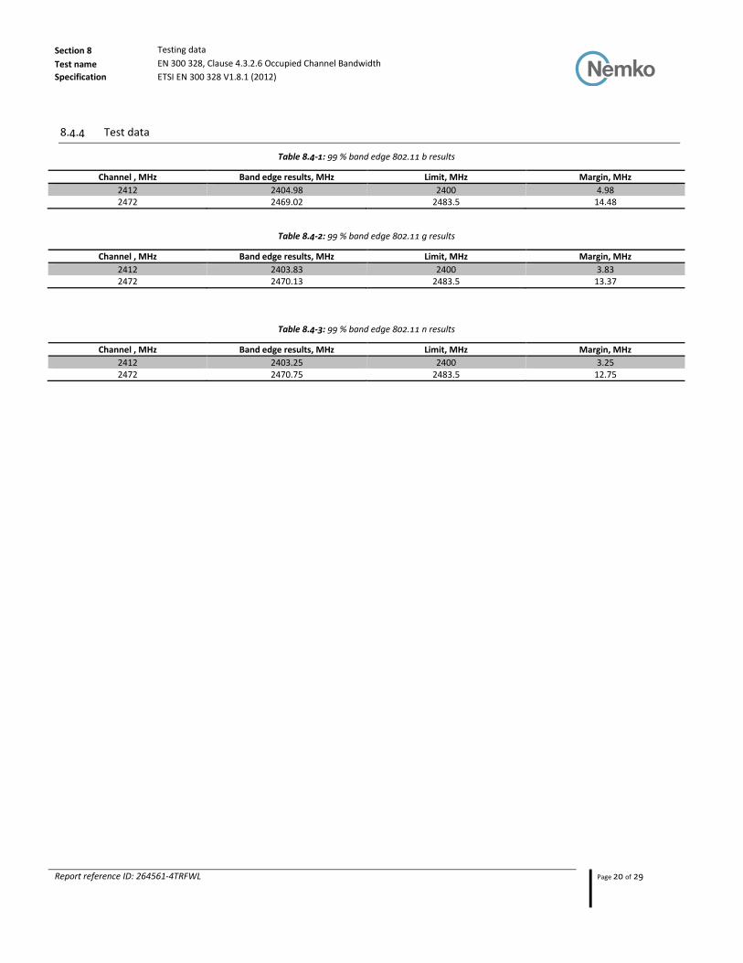
8.4.4 Test data
Table 8.4-1: 99 % band edge 802.11 b results
Channel , MHz Band edge results, MHz Limit, MHz Margin, MHz
2412 2404.98 2400 4.98 2472 2469.02 2483.5 14.48
Table 8.4-2: 99 % band edge 802.11 g results
Channel , MHz Band edge results, MHz Limit, MHz Margin, MHz
2412 2403.83 2400 3.83 2472 2470.13 2483.5 13.37
Table 8.4-3: 99 % band edge 802.11 n results
Channel , MHz Band edge results, MHz Limit, MHz Margin, MHz
2412 2403.25 2400 3.25 2472 2470.75 2483.5 12.75

Section 8 Testing data
Test name EN 300 328, Clause 4.3.2.7 Transmitter unwanted emissions in the out-of-band domain
Specification ETSI EN 300 328 V1.8.1 (2012)
Report reference ID: 264561-4TRFWL Page 21 of 29
8.5 EN 300 328 Clause 4.3.2.7 Transmitter unwanted emissions in the out-of-band domain
8.5.1 Definitions and limits
Definition:
Transmitter unwanted emissions in the out-of-band domain are emissions when the equipment is in Transmit mode, on
frequencies immediately outside the necessary bandwidth which results from the modulation process, but excluding
spurious.
Clause 4.3.2.7.2 limit The spurious emissions of the transmitter shall not exceed the values in Table 8.5-1 in the indicated bands
Table 8.5-1: Transmitter limits
Frequency range, MHz Limit
2400–2BW to 2400−BW -20 dBm 2400–BW to 2400 -10 dBm
2483.5 to 2483.5+BW -10 dBm 2483.5+BW to 2483.5+2BW -20 dBm
Notes: The above limit values apply to narrowband emissions, e.g. as caused by local oscillator leakage. The measurement bandwidth for such emissions
may be as small as necessary to achieve a reliable measurement result.
8.5.2 Test summary
Test date July 28, 2014 Temperature 21 °C
Test engineer Kevin Rose Air pressure 1003 mbar
Verdict Pass Relative humidity 38 %
8.5.3 Observations, settings and special notes
2400 MHz2400 MHz − BW2400 MHz − 2BW 2483.5 MHz 2483.5 MHz + BW 2483.5 MHz + 2BW
Spurious domain Spurious domainOut-of-band (OOB) domainOut-of-band (OOB) domain Allocated band
A
B
C
A: −10 dBm/MHz (EIRP)B: −20 dBm/MHz (EIRP)C: Spurious domain limits
BW = Occupied channel bandwidth in MHz or 1 MHz, whichever is greater
Figure 8.5-1: Transmit mask
The emissions over the range Spectrum analyser settings:
Resolution bandwidth: 1 MHz
Video bandwidth: 3 MHz
Detector mode: RMS
Trace mode: Max Hold
Sweep Points: ≥ 9 970

Section 8 Testing data
Test name EN 300 328, Clause 4.3.2.7 Transmitter unwanted emissions in the out-of-band domain
Specification ETSI EN 300 328 V1.8.1 (2012)
Report reference ID: 264561-4TRFWL Page 22 of 29
8.5.4 Test data
Table 8.5-2: Transmitter unwanted emissions in the out-of-band domain 802.11b
Frequency range, MHz
23 degrees 230 VAC
Level, dBm
70 degrees 90 VAC
Level, dBm
70 degrees 264 VAC
Level, dBm
-20 degrees 90 VAC
Level, dBm
-20 degrees 264 VAC
Level, dBm Limit, dBm
Minimum margin, dB
2400 -2BW -43.16 -43.11 -43.21 -41.08 -41.59 -20 21.08 2400 -1BW -41.96 -42.68 -43.36 -41.05 -43.03 -10 31.05
2483.5 +1BW -42.17 -42.96 -43.72 -41.05 -41.56 -10 31.05 2483.5 +2BW -40.55 -41.76 -41.91 -42.23 -41.57 -20 21.76
Table 8.5-3: Transmitter unwanted emissions in the out-of-band domain 802.11g
Frequency range, MHz
23 degrees 230 VAC
Level, dBm
70 degrees 90 VAC
Level, dBm
70 degrees 264 VAC
Level, dBm
-20 degrees 90 VAC
Level, dBm
-20 degrees 264 VAC
Level, dBm Limit, dBm
Minimum margin, dB
2400 -2BW -39.57 -43.26 -43.3 -38.78 -38.34 -20 18.34 2400 -1BW -31.56 -41.37 -41.13 -32.26 -32.39 -10 22.26
2483.5 +1BW -30.38 -43.26 -43.19 -28.5 -30.77 -10 18.5 2483.5 +2BW -41.62 -43.49 -43.56 -40.42 -42.46 -20 20.42
Table 8.5-4: Transmitter unwanted emissions in the out-of-band domain 802.11n
Frequency range, MHz
23 degrees 230 VAC
Level, dBm
70 degrees 90 VAC
Level, dBm
70 degrees 264 VAC
Level, dBm
-20 degrees 90 VAC
Level, dBm
-20 degrees 264 VAC
Level, dBm Limit, dBm
Minimum margin, dB
2400 -2BW -43.15 -43.16 -42.5 -38.03 -39.32 -20 18.03 2400 -1BW -33.34 -33.64 -32.98 -29.34 -31.48 -10 19.34
2483.5 +1BW -29.74 -31.56 -33.07 -26.93 -27.78 -10 16.93 2483.5 +2BW -39.81 -38.97 -38.95 -40.04 -40.99 -20 18.97

Section 8 Testing data
Test name EN 300 328, Clause 4.3.2.8 Transmitter unwanted emissions in the spurious domain
Specification ETSI EN 300 328 V1.8.1 (2012)
Report reference ID: 264561-4TRFWL Page 23 of 29
8.6 EN 300 328 Clause 4.3.2.8 Transmitter unwanted emissions in the spurious domain
8.6.1 Definitions and limits
Definition:
Transmitter unwanted emissions in the spurious domain are emissions outside the allocated band and outside the out-of-
band domain, when the equipment is in Transmit mode.
These measurements shall only be performed at normal test conditions.
Clause 4.3.2.8.2 limit The spurious emissions of the transmitter shall not exceed the values in Table 8.6-1 in the indicated bands
Table 8.6-1: Transmitter limits
Frequency range Limit when operating, dBm Measurement Bandwidth
30 MHz to 47 MHz -36 dBm 100 kHz 47 MHz to 74 MHz -54 dBm 100 kHz
74 MHz to 87,5 MHz -36 dBm 100 kHz 87,5 MHz to 118 MHz -54 dBm 100 kHz 118 MHz to 174 MHz -36 dBm 100 kHz 174 MHz to 230 MHz -54 dBm 100 kHz 230 MHz to 470 MHz -36 dBm 100 kHz 470 MHz to 862 MHz -54 dBm 100 kHz
862 MHz to 1 GHz -36 dBm 100 kHz 1 GHz to 12,75 GHz -30 dBm 1 MHz
Notes: The above limit values apply to narrowband emissions, e.g. as caused by local oscillator leakage. The measurement bandwidth for such emissions
may be as small as necessary to achieve a reliable measurement result.
8.6.2 Test summary
Test date July 28, 2014 Temperature 21 °C
Test engineer Kevin Rose Air pressure 1003 mbar
Verdict Pass Relative humidity 38 %

Section 8 Testing data
Test name EN 300 328, Clause 4.3.2.8 Transmitter unwanted emissions in the spurious domain
Specification ETSI EN 300 328 V1.8.1 (2012)
Report reference ID: 264561-4TRFWL Page 24 of 29
8.6.3 Observations, settings and special notes
The spectrum was searched from 30 MHz to 12.75 GHz. Cabinet radiation measurements were performed a 3 m distance. No emission within 10 dB of the limit were detected The pre-scans were performed with spectrum analyzer using following settings:
The emissions over the range 30 MHz to 1 000 MHz shall be identified. Spectrum analyser settings:
Resolution bandwidth: 100 kHz
Video bandwidth: 300 kHz
Detector mode: Peak
Trace mode: Max Hold
Sweep Points: ≥ 9 970
The emissions over the range 1 GHz to 12.75 GHz shall be identified. Spectrum analyser settings:
Resolution bandwidth: 1 MHz
Video bandwidth: 3 MHz
Detector mode: Peak
Trace mode: Max Hold
Sweep Points: ≥ 11 750
Sweep time: For non-continuous transmissions (duty cycle less than 100 %), the sweep time shall be sufficiently long, such that for each 1 MHz frequency step, the measurement time is greater than two transmissions of the UUT. Allow the trace to stabilize. Any emissions identified during the sweeps above that fall within the 6 dB range below the applicable limit or above, shall be individually measured
Section 8 Testing data
Test name EN 300 328, Clause 4.3.2.8 Transmitter unwanted emissions in the spurious domain
Specification ETSI EN 300 328 V1.8.1 (2012)
Report reference ID: 264561-4TRFWL Page 25 of 29
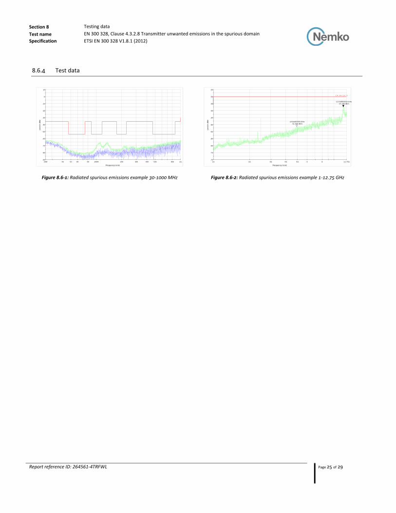
8.6.4 Test data
Figure 8.6-1: Radiated spurious emissions example 30-1000 MHz Figure 8.6-2: Radiated spurious emissions example 1-12.75 GHz
-90
-80
-70
-60
-50
-40
-30
-20
-10
0
10
25M 40 50 60 80 100M 200 300 400 500 800 1G
Leve
l in
dB
m
Frequency in Hz
-75
-70
-65
-60
-55
-50
-45
-40
-35
-30
-25
1G 2G 3G 4G 5G 6 8 12.75G
Leve
l in
dB
m
Frequency in Hz
E N 300 220 Tx
4.914400000 GHz
-51.563 dBm
12.019950000 GHz
-37.266 dBm

Section 8 Testing data
Test name EN 300 328, Clause 4.3.2.9 Receiver spurious emissions
Specification ETSI EN 300 328 V1.8.1 (2012)
Report reference ID: 264561-4TRFWL Page 26 of 29
8.7 EN 300 328 Clause 4.3.2.9 Receiver spurious emissions
8.7.1 Definitions and limits
Definition:
Transmitter unwanted emissions in the spurious domain are emissions outside the allocated band and outside the out-of-
band domain, when the equipment is in Transmit mode.
These measurements shall only be performed at normal test conditions.
Clause 4.3.2.9.2 limit The spurious emissions of the transmitter shall not exceed the values in 8.7.1 in the indicated bands
Table 8.7-1: Spurious emission limits for receivers
Frequency range Maximum power, e.r.p. Measurement bandwidth
30 MHz to 1 GHz -57 dBm 100 kHz 1 GHz to 12.75 GHz --47 dBm 1 MHz
8.7.2 Test summary
Test date July 28, 2014 Temperature 21 °C
Test engineer Kevin Rose Air pressure 1003 mbar
Verdict Pass Relative humidity 38 %
8.7.3 Observations, settings and special notes
The spectrum was searched from 30 MHz to 12.75 GHz. Cabinet radiation measurements were performed a 3 m distance. No RX radio emissions were detected within 10 dB of the limit. The pre-scans were performed with spectrum analyzer using following settings:
The emissions over the range 30 MHz to 1 000 MHz shall be identified. Spectrum analyser settings:
Resolution bandwidth: 100 kHz
Video bandwidth: 300 kHz
Detector mode: Peak
Trace mode: Max Hold
Sweep Points: ≥ 9 970
The emissions over the range 1 GHz to 12.75 GHz shall be identified. Spectrum analyser settings:
Resolution bandwidth: 1 MHz
Video bandwidth: 3 MHz
Detector mode: Peak
Trace mode: Max Hold
Sweep Points: ≥ 11 750
Section 8 Testing data
Test name EN 300 328, Clause 4.3.2.9 Receiver spurious emissions
Specification ETSI EN 300 328 V1.8.1 (2012)
Report reference ID: 264561-4TRFWL Page 27 of 29
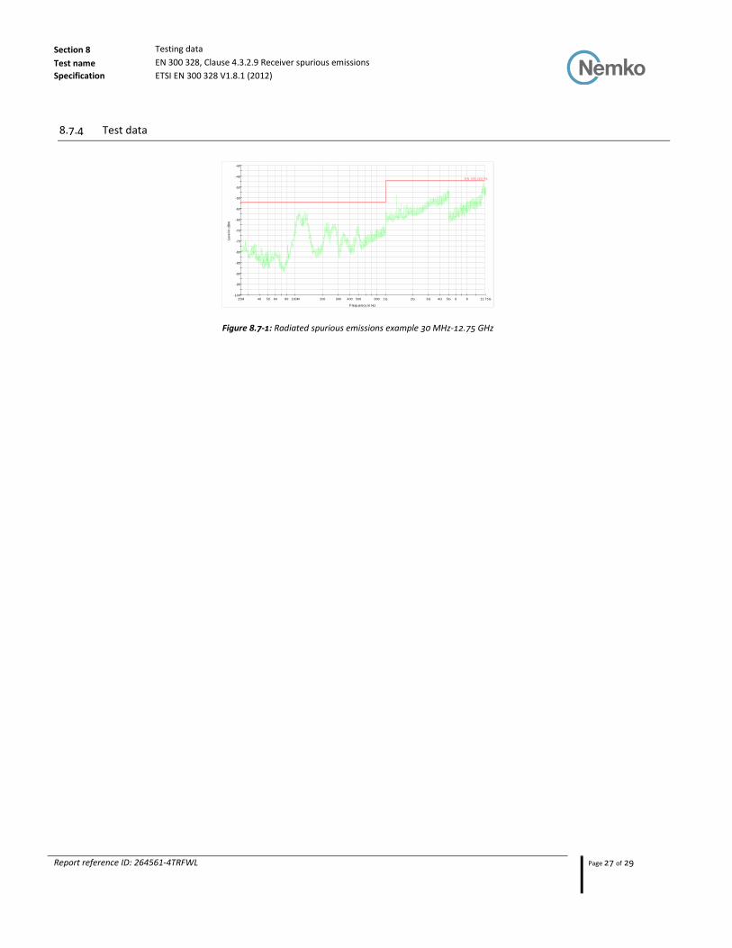
8.7.4 Test data
Figure 8.7-1: Radiated spurious emissions example 30 MHz-12.75 GHz
-100
-95
-90
-85
-80
-75
-70
-65
-60
-55
-50
-45
-40
25M 40 50 60 80 100M 200 300 400 500 800 1G 2G 3G 4G 5G 6 8 12.75G
Leve
l in
dB
m
Frequency in Hz
E N 300 220 Rx

Section 8 Testing data
Test name Clause 4.3.2.10 Receiver blocking
Specification ETSI EN 300 328 V1.8.1 (2012)
Report reference ID: 264561-4TRFWL Page 28 of 29
8.8 Clause 4.3.2.10 Receiver blocking
8.8.1 Definitions and limits
Definition
Receiver blocking is a measure of the capability of the adaptivity mechanism to operate as intended (see clause 4.3.2.5) in the
presence of an unwanted signal (blocking signal) on frequencies other than those of the operating channel and the adjacent
channels.
Clause 4.3.2.10.2 limit Adaptive equipment using wide band modulations other than FHSS, shall comply with the requirements defined in clauses 4.3.2.5.1 (non-LBT based DAA) or 4.3.2.5.2 (LBT based DAA) in the presence of a blocking signal with characteristics as provided in table below
Table 8.8-1: Receiver blocking parameters
Equipment Type (LBT / non- LBT)
Wanted signal mean power from companion device
Blocking signal Frequency, MHz
Blocking signal power, dBm Type of interfering signal
LBT sufficient to maintain the
link (see note 2) 2 395 or 2 488,5
(see note 1) −30 CW
Non-LBT −30 dBm
NOTE 1: The highest blocking frequency shall be used for testing the lowest operating channel, while the lowest blocking frequency shall be used for testing
the highest operating channel.
NOTE 2: A typical value which can be used in most cases is −50 dBm/MHz.
8.8.2 Test summary
Test date July 28, 2014 Temperature 21 °C
Test engineer Kevin Rose Air pressure 1003 mbar
Verdict Pass Relative humidity 38 %
8.8.3 Observations, settings and special notes
None
8.8.4 Test data
Please refer to the section 8.3 of this document for the test results.
Section 9: Block diagrams of test set-ups
Report reference ID: 264561-4TRFWL Page 29 of 29
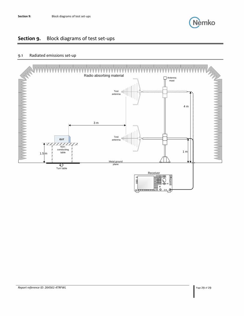
Section 9. Block diagrams of test set-ups
9.1 Radiated emissions set-up
Metal ground
plane
3 m
Non-
conducting
table1.5 m
Receiver
EUT
Turn table
Radio absorbing material
1 m
4 m
Antenna
mast
Test
antenna
Test
antenna