test results using iris and airy disc for the bpm
TRANSCRIPT

Test Results using Iris and Airy disc for the BPM Alignment of SCSS (SPring-8 Compact SASE Source) Prototype Accelerator
* JASRI (Japan Synchrotron Radiation Research Institute)** RIKEN
S. Matsui*, C.Zhang*, M.Yabshi*, S.Goto*, H.Kimura*, S.Kojima** ,and T. Shintake**
FEL machine Plan at SPrng-8 site
λ: 0.06 nm Energy : 8 GeV
length : 800mWe are making basic design of the building, now.
Contents1) SCSS prototype accelerator2) How to align BPM for FEL?3) Principle : Using Laser, Iris, and Airy disc4) Instruments:
(1) Laser, (2) BPM with Iris, (3) CCD camera5) Calculation of the center6) Test Results :
(1) Calibration between BPM and Iris, (2) Diameter and brightness of airy disc, (3)Reproducebility, (4)Fluctuation, (5) Stability, (6) Effect due to Gaussian, (7) Check of laser and Iris - airy disc system
7) Summary8) Alignment Plan of 18 BPMs for 8 GeV
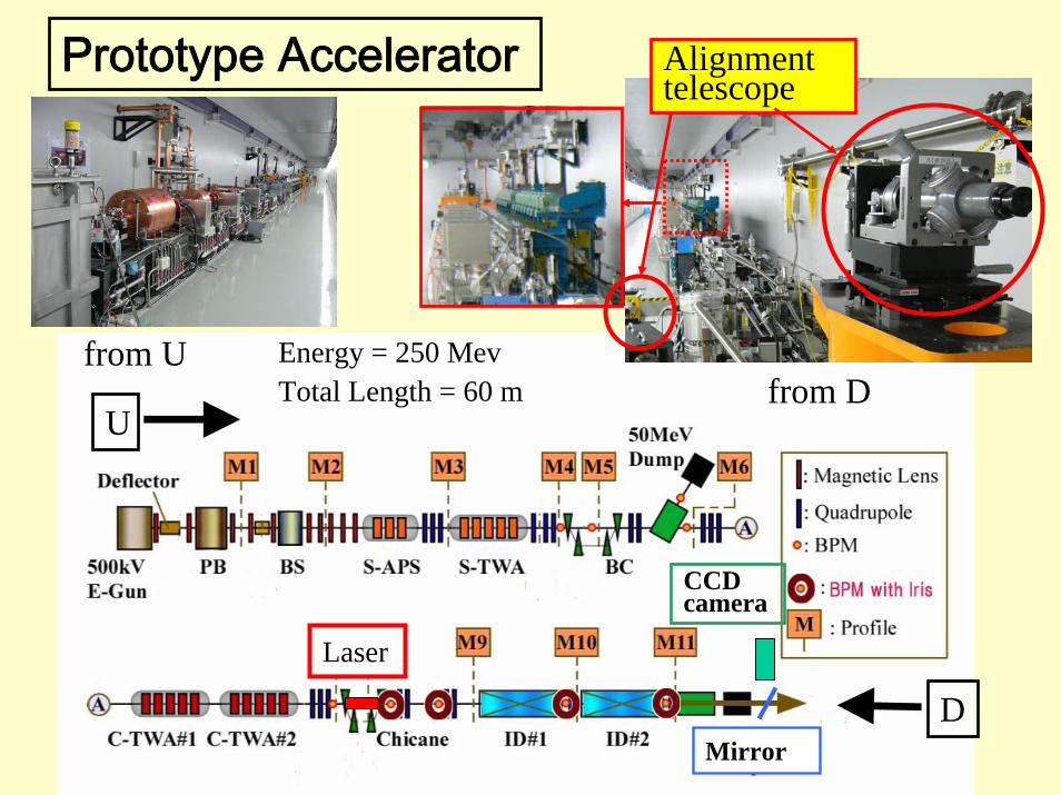
Prototype Accelerator
Energy = 250 MevTotal Length = 60 m
U
D
from Ufrom D
Alignment telescope
CCD camera
Mirror
Laser
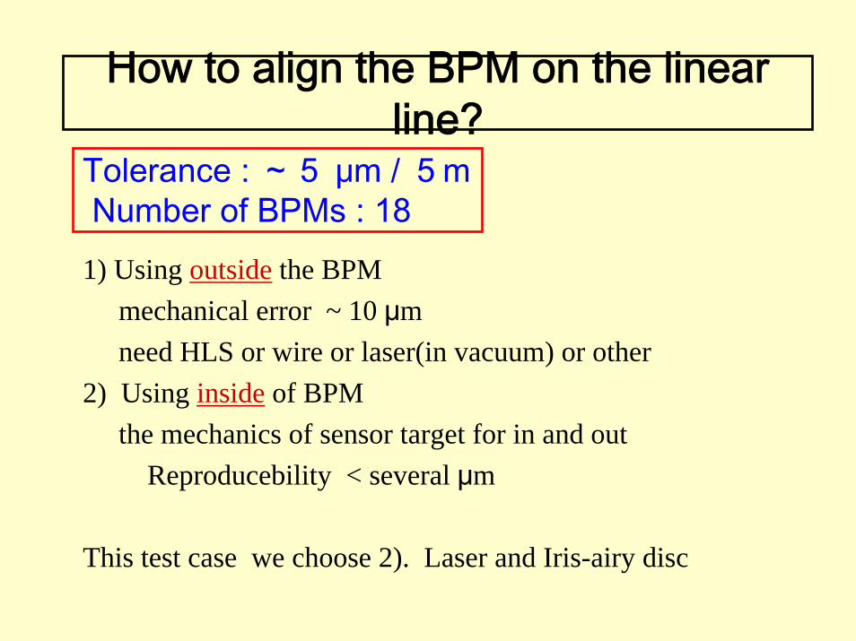
How to align the BPM on the linear line?
1) Using outside the BPMmechanical error ~ 10 μmneed HLS or wire or laser(in vacuum) or other
2) Using inside of BPMthe mechanics of sensor target for in and out
Reproducebility < several μm
This test case we choose 2). Laser and Iris-airy disc
Tolerance : ~5 μm / 5m Number of BPMs : 18
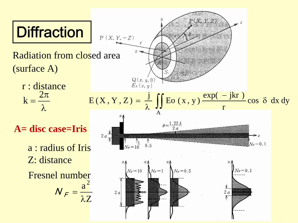
dydxcosr
)jkrexp()y,x(Eoj)Z,Y,X(EA∫∫ δ
−λ
=
Za 2
λ=FN
a : radius of IrisZ: distanceFresnel number
DiffractionRadiation from closed area (surface A)
r : distance
λπ
=2k
A= disc case=Iris

φ3mm Iris
φ2.5mm Iris
0.5m 2.5m 5m
10m
(from Iris)
Images after the Iris
5mm
7 1.4 φ2.5mm Iris
10m
0.350.7=λZa2
5mm
Iris Φ =3mm
Airy disc
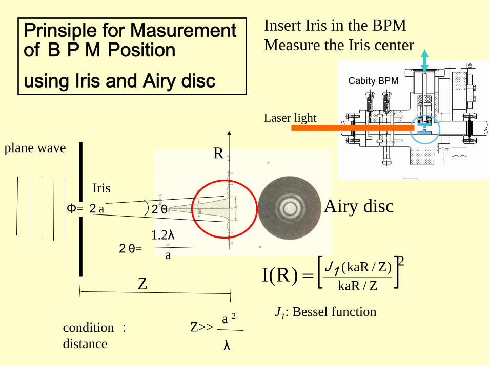
Insert Iris in the BPMMeasure the Iris center
plane wave
IrisΦ= 2a
Z
Z>> a 2
λcondition :distance
[ ]2Z/kaR)Z/kaR()R(I 1J=
2θ
2θ=1.2λ
a
Prinsiple for Masurementof BPM Position using Iris and Airy disc
Laser light
R
Airy disc
J1: Bessel function

Instruments(1)He-Ne Laser
λ=633nm(red) Output Power=7mWBeam diameter=0.81mm (1/e2)Beam divergence = 1 mradPointing stability < 0.02 mrad
Expander 10×ND filter Laer tubeUniphase 1137P
XZ stage ×2ResolutionX: 2.5μmZ: 1.25μm

Iris
XZ stageResolutionX: 0.1μmZ: 0.1μm
Instruments(2)BPM with Iris
CavityBPM XZ
stageBPM is on this stage.
Iris controllerstage controller
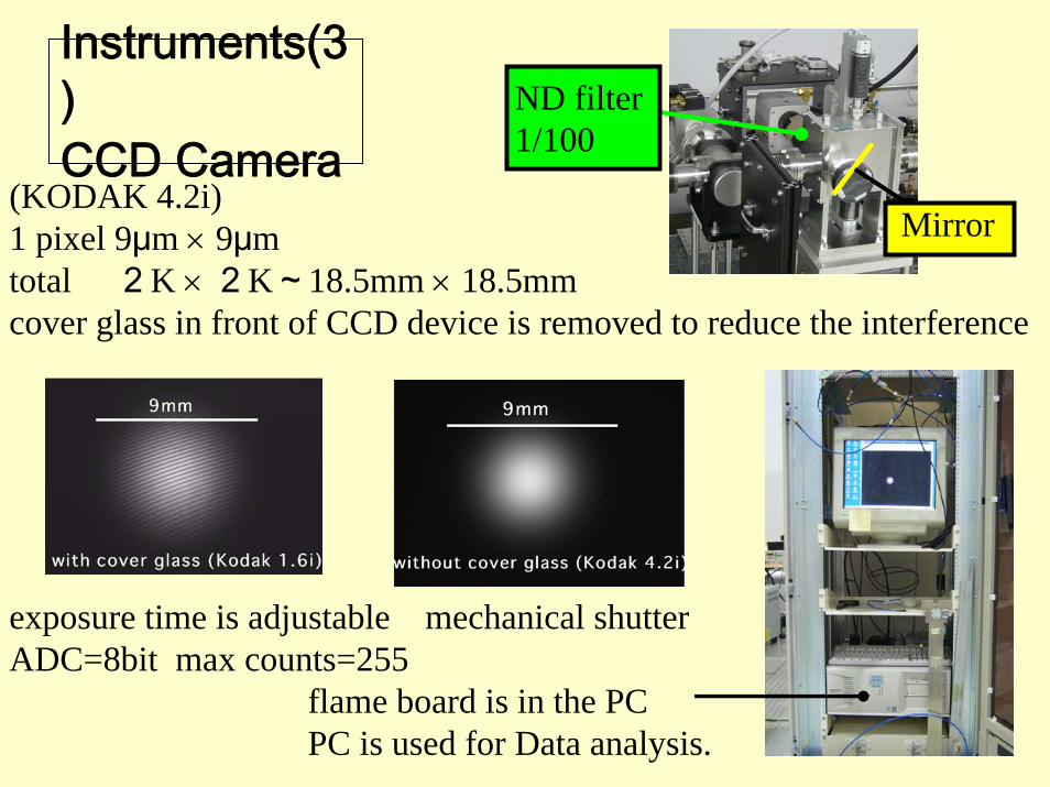
(KODAK 4.2i) 1 pixel 9μm × 9μmtotal 2K × 2K~18.5mm × 18.5mmcover glass in front of CCD device is removed to reduce the interference
exposure time is adjustable mechanical shutterADC=8bit max counts=255
flame board is in the PCPC is used for Data analysis.
ND filter 1/100
Mirror
Instruments(3)CCD Camera
18.4mm
1pixel=9μm×9μm
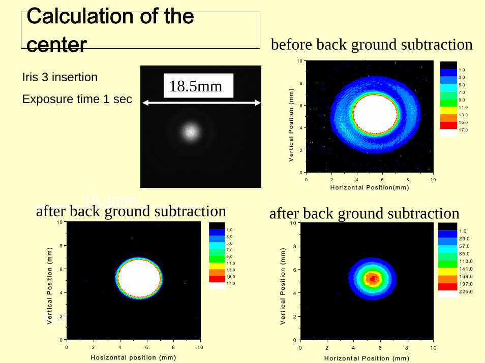
Calculation of the center
0 2 4 6 8 100
2
4
6
8
10
H o s izo n t al pos it ion (m m )
Ver
tica
l P
osit
ion
(mm
)
1 .03 .05.07.09.011 .013 .015 .017 .0
0 2 4 6 8 100
2
4
6
8
10
H or izon t al P os it ion (m m )
Ver
tica
l P
osit
ion
(mm
)
1 .029.057.085.0113.0141.0169.0197.0225.0
0 2 4 6 8 100
2
4
6
8
10
H or izon t al P os it ion(m m )
Ver
tica
l P
osit
ion
(mm
)
1 .0
3 .0
5.0
7.0
9.0
11.0
13.0
15.0
17.0
Iris 3 insertion
Exposure time 1 sec18.5mm
after back ground subtraction after back ground subtraction
before back ground subtraction
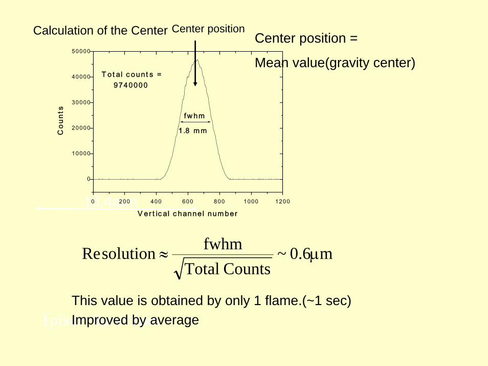
Calculation of the Center
m6.0~CountsTotal
fwhmsolutionRe μ≈
18.4mm
Center position =
Mean value(gravity center)
Center position
0 200 400 600 800 1000 1200
0
10000
20000
30000
40000
50000
1pixel=9μm×9μmThis value is obtained by only 1 flame.(~1 sec) Improved by average
f w hm
T o t al c oun t s = 9740000
1 .8 m m
Cou
nts
V e r t ic al c hanne l num ber

Test result(1)Calibration between Cavity Center and Iris one
1)Search the center position as measuring output from cavity BPMWire : Cu 0.05mm RF: 4 to 6 GHz
2)Insert Iris and same search as 1)
Results of 3 BPMsRF center - Iris center = horizontal :2.5, -2, -0.5, μm
vertical : -43.5, -24.5, -46.5μm
Wire
Iris center is lower than the cavity center.
measurement
BPM
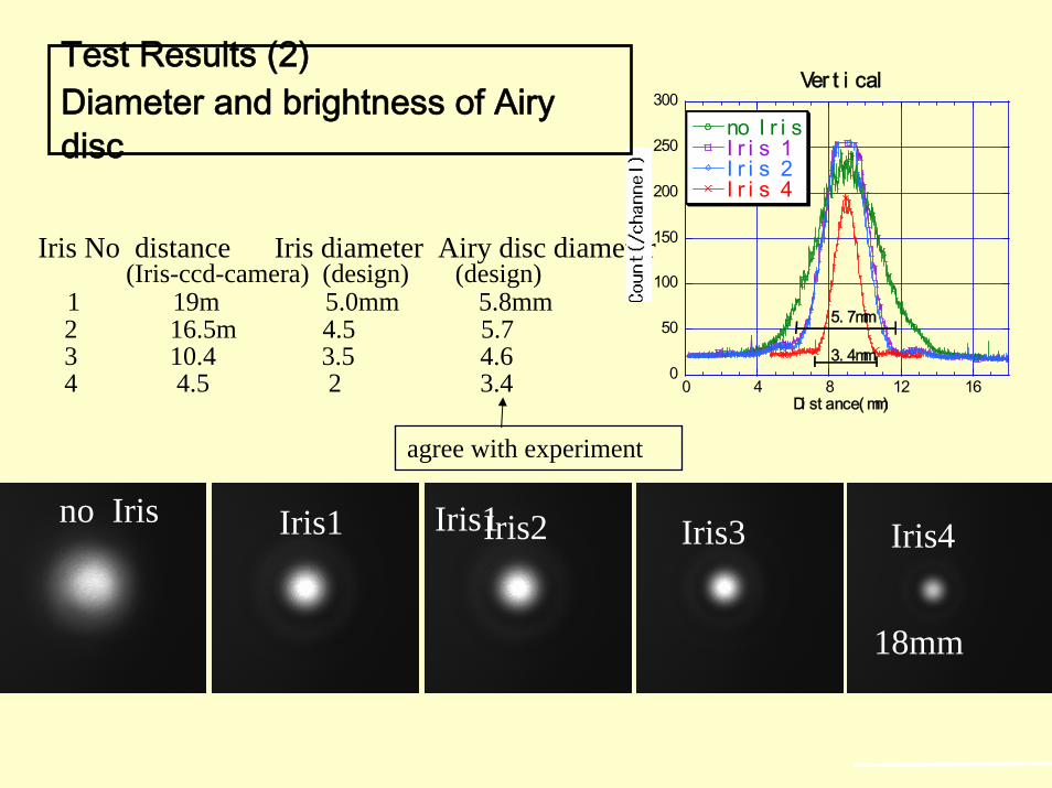
Iris1 Iris2 Iris3 Iris4no Iris
18mm
Iris No distance Iris diameter Airy disc diameter(Iris-ccd-camera) (design) (design)
1 19m 5.0mm 5.8mm2 16.5m 4.5 5.73 10.4 3.5 4.64 4.5 2 3.4
Iris1
0
50
100
150
200
250
300
0 4 8 12 16
Ver t i cal
no I r i sI r i s 1I r i s 2I r i s 4
Di st ance( mm)
3. 4mm
5. 7mm
Test Results (2)Diameter and brightness of Airydisc
agree with experiment

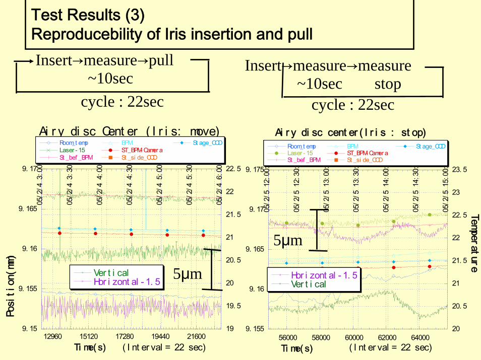
Test Results (3)Reproducebility of Iris insertion and pull
distance Iris-CCD camera =1 m
9. 155
9. 16
9. 165
9. 17
9. 175
20
20. 5
21
21. 5
22
22. 5
23
23. 5
56000 58000 60000 62000 64000
05/2
/5 1
2:00
:00
05/2
/5 1
2:30
:00
05/2
/5 1
3:00
:00
05/2
/5 1
3:30
:00
05/2
/5 1
4:00
:00
05/2
/5 1
4:30
:00
05/2
/5 1
5:00
:00
Ai r y di sc cent er ( I r i s : st op)
Hor i zont al - 1. 5Ver t i cal
Room_t empLaser - 15St _bef _BPM
BPMST_BPM- Camer aSt _si de_CCD
St age_CCD
Ti me( s) ( I nt er val = 22 sec)
Temperature
9. 15
9. 155
9. 16
9. 165
9. 17
19
19. 5
20
20. 5
21
21. 5
22
22. 5
12960 15120 17280 19440 21600
05/2
/4 3
:00:
00
05/2
/4 3
:30:
00
05/2
/4 4
:00:
00
05/2
/4 4
:30:
00
05/2
/4 5
:00:
00
05/2
/4 5
:30:
00
05/2
/4 6
:00:
00
Ai r y di sc Cent er ( I r i s: move)
Ver t i calHor i zont al - 1. 5
Room_t empLaser - 15St _bef _BPM
BPMST_BPM- Camer aSt _si de_CCD
St age_CCD
Posi
tion
(mm)
Ti me( s) ( I nt er val = 22 sec)
Insert→measure→pull~10sec
Insert→measure→measure~10sec stop
cycle : 22sec cycle : 22sec
Test Results (3)Reproducebility of Iris insertion and pull
5μm
5μm
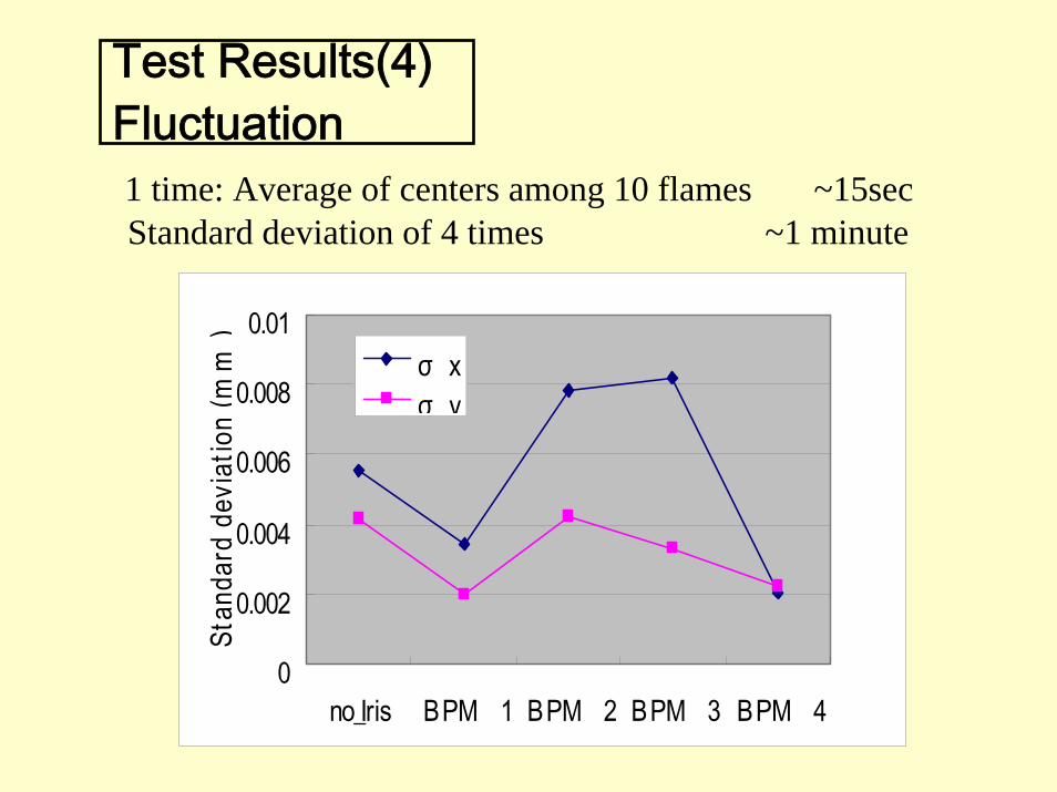
Standard deviation of 4 times ~1 minute
0
0.002
0.004
0.006
0.008
0.01
no_Iris BPM 1 BPM 2 BPM 3 BPM 4
Stan
dard
dev
iatio
n(m
m)
σ xσ y
1 time: Average of centers among 10 flames ~15sec
Test Results(4)Fluctuation
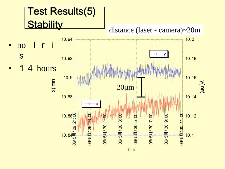
• no Iris
• 14 hours
10. 84
10. 86
10. 88
10. 9
10. 92
10. 94
10. 1
10. 12
10. 14
10. 16
10. 18
10. 2
06/5
月/2
9 21
:00
06/5
月/2
9 23
:00
06/5
月/3
0 1:
00
06/5
月/3
0 3:
00
06/5
月/3
0 5:
00
06/5
月/3
0 7:
00
06/5
月/3
0 9:
00
06/5
月/3
0 11
:00
Dat aCent May29- 30
x
yx(
mm) y(mm)
t i me
Test Results(5)Stability
20μm
distance (laser - camera)~20m
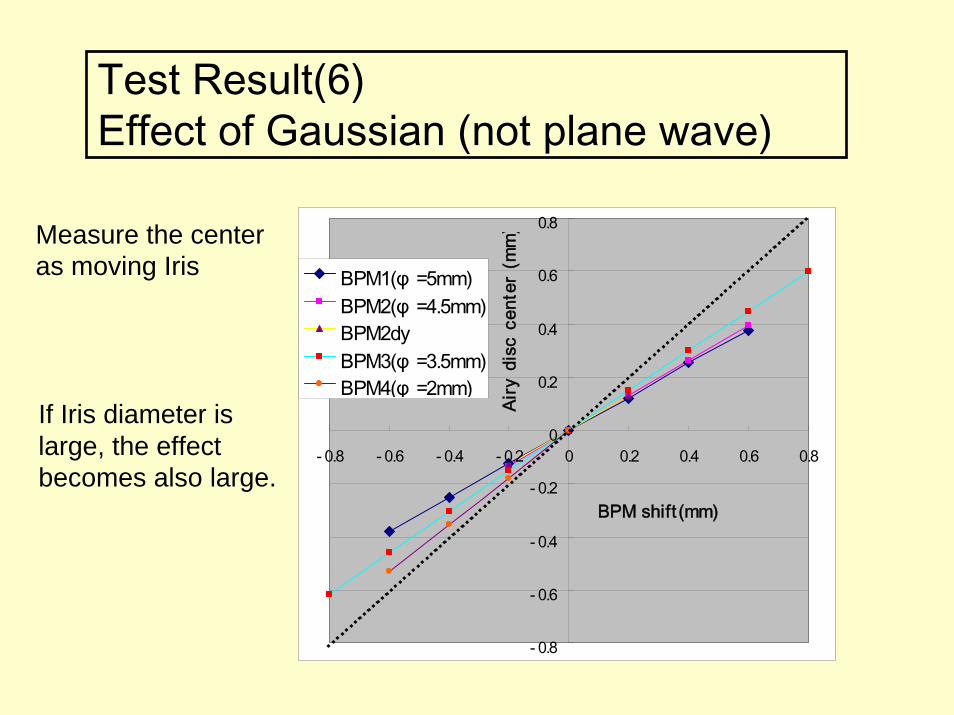
Test Result(6)Effect of Gaussian (not plane wave)
- 0.8
- 0.6
- 0.4
- 0.2
0
0.2
0.4
0.6
0.8
- 0.8 - 0.6 - 0.4 - 0.2 0 0.2 0.4 0.6 0.8
BPM1(φ =5mm)BPM2(φ =4.5mm)BPM2dyBPM3(φ =3.5mm)BPM4(φ =2mm)
BPM shift (mm)Ai
ry d
isc
cent
er (
mm
)Measure the center as moving Iris
If Iris diameter is large, the effect becomes also large.

Test Result(6)Effect of Gaussian (not plane wave)
calculation results
0
20
40
60
80
100
120
140
2.5 3 3.5 4 4.51/e half-width of Gaussian beam (mm)
Shi
ft (m
icro
ns)
BPM [email protected] m, 5 mmBPM [email protected] m, 4.5 mmBPM [email protected] m, 3.5 mmBPM [email protected] m, 2 mm
Offset 300 microns No background subtraction
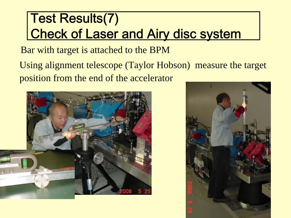
Test Results(7)Check of Laser and Airy disc system
Bar with target is attached to the BPMUsing alignment telescope (Taylor Hobson) measure the targetposition from the end of the accelerator
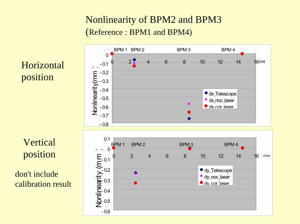
Nonlinearity of BPM2 and BPM3 (Reference : BPM1 and BPM4)
- 0.8- 0.7- 0.6- 0.5- 0.4- 0.3- 0.2- 0.1
00 2 4 6 8 10 12 14 16
dx_Telescopedx_noc_laserdx cor laser
BPM 1 BPM 2 BPM 3 BPM 4
(m)
Nonl
inea
rity(
mm
)
- 0.6
- 0.5
- 0.4
- 0.3
- 0.2
- 0.1
0
0.1
0 2 4 6 8 10 12 14 16
dy_Telescopedy_noc_laserdy cor laser
Nonl
inea
rity(
mm
)
(m)
BPM 4BPM 1 BPM 2 BPM 3
Horizontal position
Vertical position
don't include calibration result
Summary• It is possible to measure the position of Iris inside the BPM chamber
(diameter 20 mm) using airy disc for 20 m range.• If using red He-Ne laser, it is difficult to travel through 20mm inner
diameter for more than 30m at one time.• It is necessary to estimate the accuracy of this Iris-airy disc system.
It is necessary to get the flatness of the response in the CCD device. Defect pixels are corrected using next pixel values.
• Check by the other method is also necessary. For example, WPS, HLS, and so on.
• It is important to align the vacuum chamber so that the laser light is not blocked.
• The effect of Gaussian beam must be considered.• It is necessary to improve the reproducibility of Iris insertion and pull
out.• The fluctuation should be improved by searching the reason.

Alignment Plan of 18 BPMs for 8 GeV
BPM with Iris
Mirror
CCD Camera
He-Ne Laser
30m
1 unit : 6.3m
size of parallel lightλ=633nm(red)
distance diameter5m ~ 3 mm50m ~ 9 mm100m ~14 mm
tail part is not included
