test stand for the characterisation of thermal interface ... · test stand for the characterisation...
TRANSCRIPT
© M. Abo Ras, April 2012
Page 1
13th LEIBNIZ CONFERENCE OF ADVANCED SCIENCE26. - 27. April 2012
NANOSCIENCE 2012
Test stand for the Characterisation of Thermal Interface Materials from the macro level up to the nano level
Mohamad Abo Ras
Berliner Nanotest und Design GmbH and
Fraunhofer Institute for Electronic Nanosystems (ENAS)
© M. Abo Ras, April 2012
Page 2
• Application of Thermal interface Materials
• Characterization of thermal interface materials
• New platform for different modules for the
characterization of TIM
• Characterization capabilities
• Interesting results
• Summary
Outline

© M. Abo Ras, April 2012
Page 3
Motivation
© M. Abo Ras, April 2012
Page 4
Applications of thermal interface materials
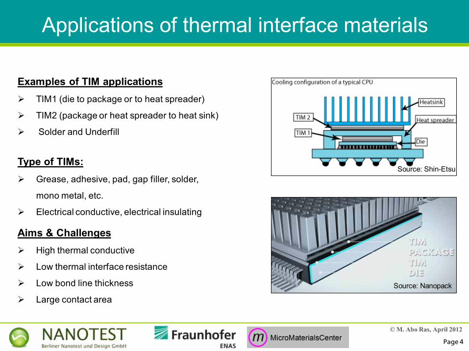
Examples of TIM applications TIM1 (die to package or to heat spreader)
TIM2 (package or heat spreader to heat sink)
Solder and Underfill
Aims & Challenges High thermal conductive
Low thermal interface resistance
Low bond line thickness
Large contact area
Type of TIMs: Grease, adhesive, pad, gap filler, solder,
mono metal, etc.
Electrical conductive, electrical insulating
Source: Shin-Etsu
Source: Nanopack
© M. Abo Ras, April 2012
Page 5
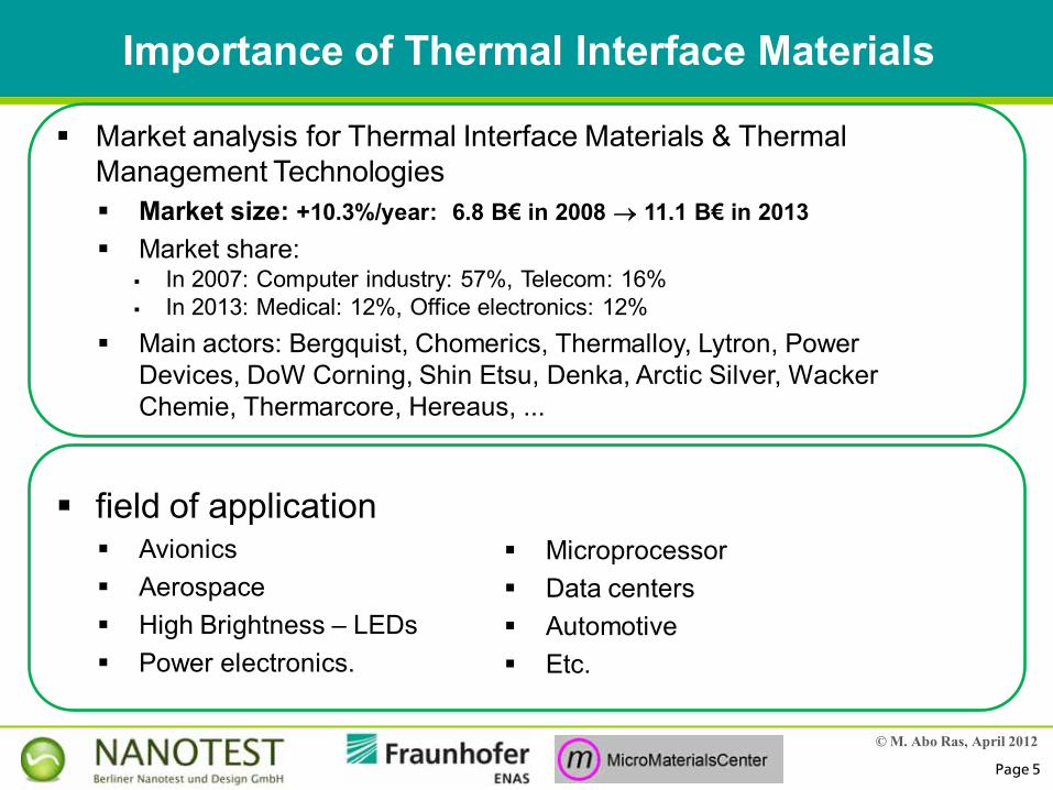
Market analysis for Thermal Interface Materials & Thermal Management Technologies Market size: +10.3%/year: 6.8 B€ in 2008 11.1 B€ in 2013 Market share:
In 2007: Computer industry: 57%, Telecom: 16% In 2013: Medical: 12%, Office electronics: 12%
Main actors: Bergquist, Chomerics, Thermalloy, Lytron, Power Devices, DoW Corning, Shin Etsu, Denka, Arctic Silver, WackerChemie, Thermarcore, Hereaus, ...
field of application Avionics Aerospace High Brightness – LEDs Power electronics.
Microprocessor Data centers Automotive Etc.
Importance of Thermal Interface Materials
© M. Abo Ras, April 2012
Page 6
TAmbiant
Gate
Buried Oxide
Silicon substrate
TIM 1Lid / Spreader
TIM 2
Heatsink
Junction
Ambient
TJunction
TCase
RthJ-C
RthC-A
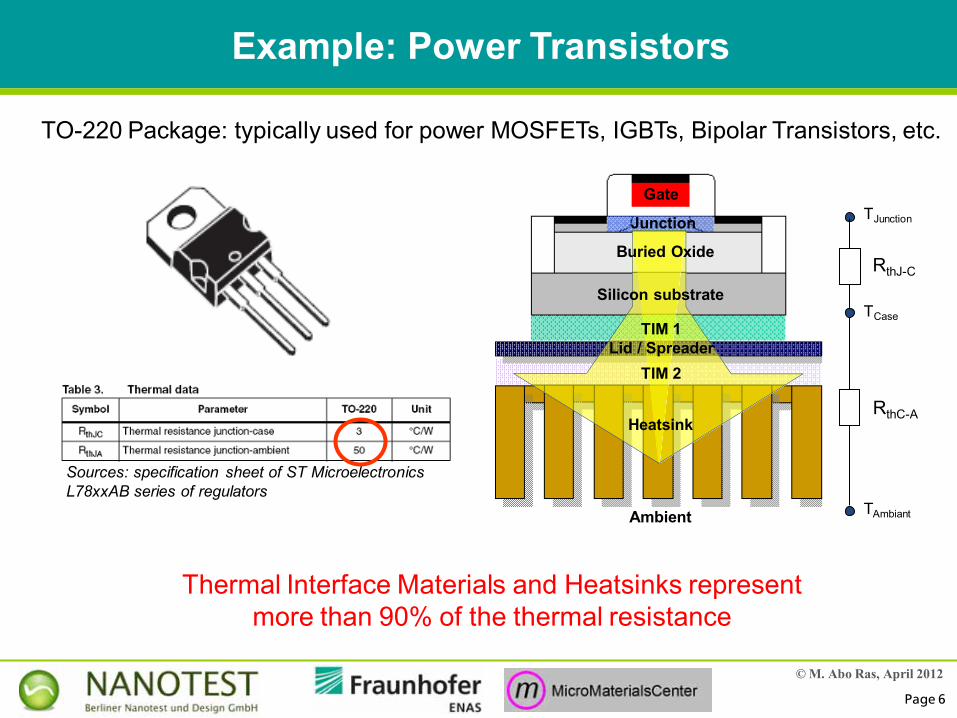
TO-220 Package: typically used for power MOSFETs, IGBTs, Bipolar Transistors, etc.
Sources: specification sheet of ST MicroelectronicsL78xxAB series of regulators
Thermal Interface Materials and Heatsinks representmore than 90% of the thermal resistance
Example: Power Transistors
© M. Abo Ras, April 2012
Page 7
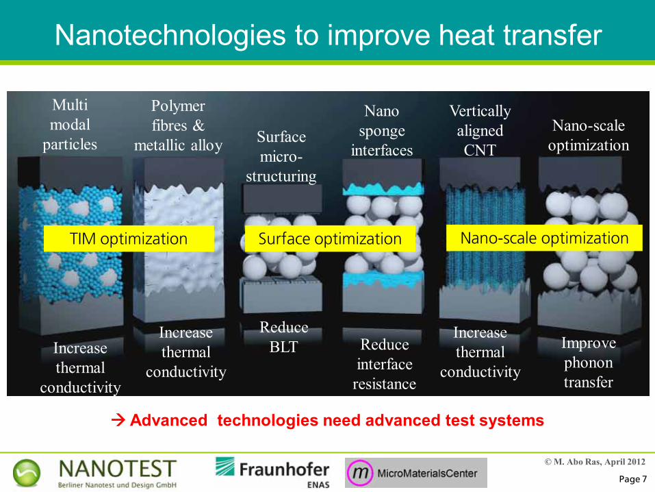
Nanotechnologies to improve heat transfer
Multi modal
particles
Polymer fibres &
metallic alloy Surface micro-
structuring
Nano sponge
interfaces
Vertically aligned CNT
Nano-scale optimization
Increase thermal
conductivity
Increase thermal
conductivity
ReduceBLT Reduce
interface resistance
Improve phonon transfer
Increase thermal
conductivity
TIM optimization Surface optimization Nano-scale optimization
Advanced technologies need advanced test systems

© M. Abo Ras, April 2012
Page 8
Characterization of Thermal Interface Materials
© M. Abo Ras, April 2012
Page 9
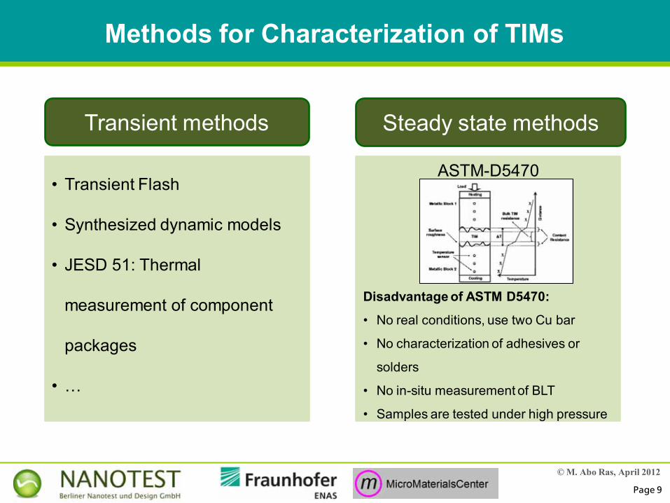
Transient methods Steady state methods
Methods for Characterization of TIMs
• Transient Flash
• Synthesized dynamic models
• JESD 51: Thermal
measurement of component
packages
• …
ASTM-D5470
Disadvantage of ASTM D5470:
• No real conditions, use two Cu bar
• No characterization of adhesives or
solders
• No in-situ measurement of BLT
• Samples are tested under high pressure
© M. Abo Ras, April 2012
Page 10
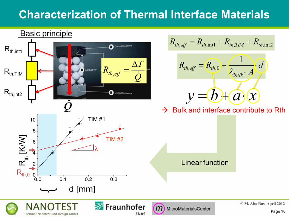
Characterization of Thermal Interface Materials
Rth,int1
Rth,int2
Rth,TIMd
ARR
bulktheffth
10,,
2int,,1int,, thTIMththeffth RRRR Basic principle
Linear function
QTR effth
,
xaby bA
0.0 0.1 0.2 0.30
2
4
6
8
10
R th [K
/W]
d [mm]
Gel
Folie
Rth,0
TIM #1
TIM #2
λ
Bulk and interface contribute to Rth
© M. Abo Ras, April 2012
Page 11
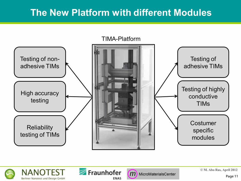
The New Platform with different Modules
TIMA-Platform
Testing of adhesive TIMs
Testing of non-adhesive TIMs
High accuracy testing
Testing of highly conductive
TIMs
Reliability testing of TIMs
Costumer specific modules
© M. Abo Ras, April 2012
Page 12
2 axes Goniometer
LVDT
Load cell
Stepper motor
Inclinesensor
Water cooler
Inclinesensor
Water cooler
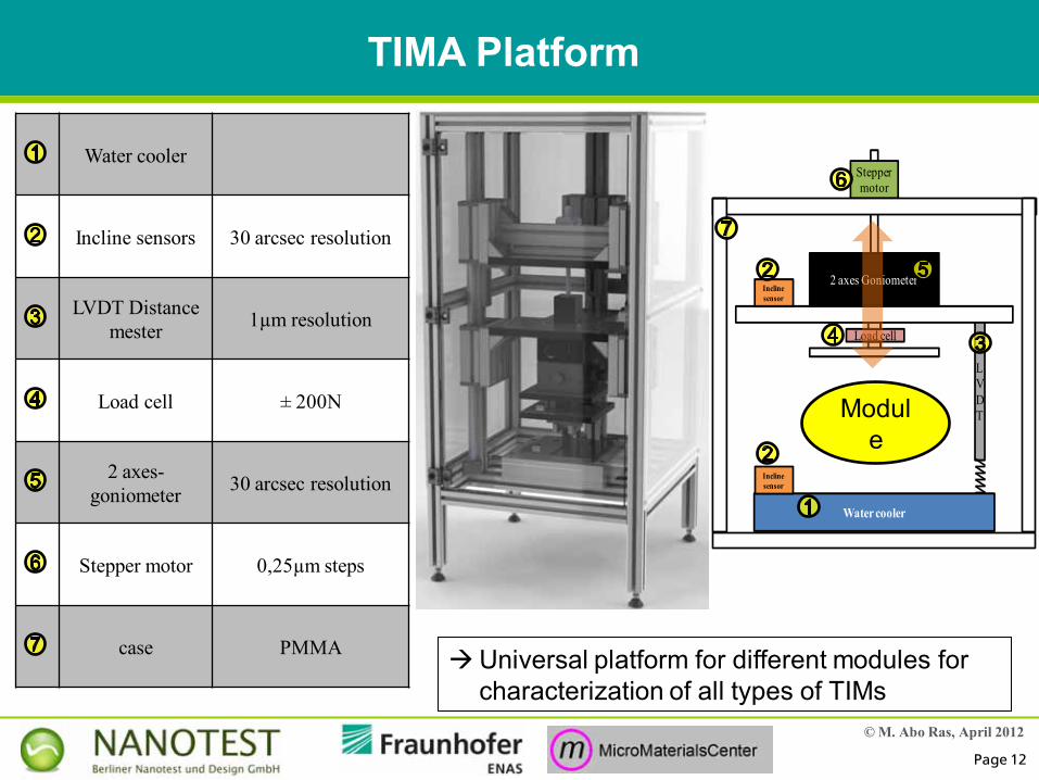
Incline sensors 30 arcsec resolution
LVDT Distance mester 1µm resolution
Load cell ± 200N
2 axes-goniometer 30 arcsec resolution
Stepper motor 0,25µm steps
case PMMA
Goniometer
Module
TIMA Platform
Universal platform for different modules for characterization of all types of TIMs
Goniometer
Load cell
© M. Abo Ras, April 2012
Page 13
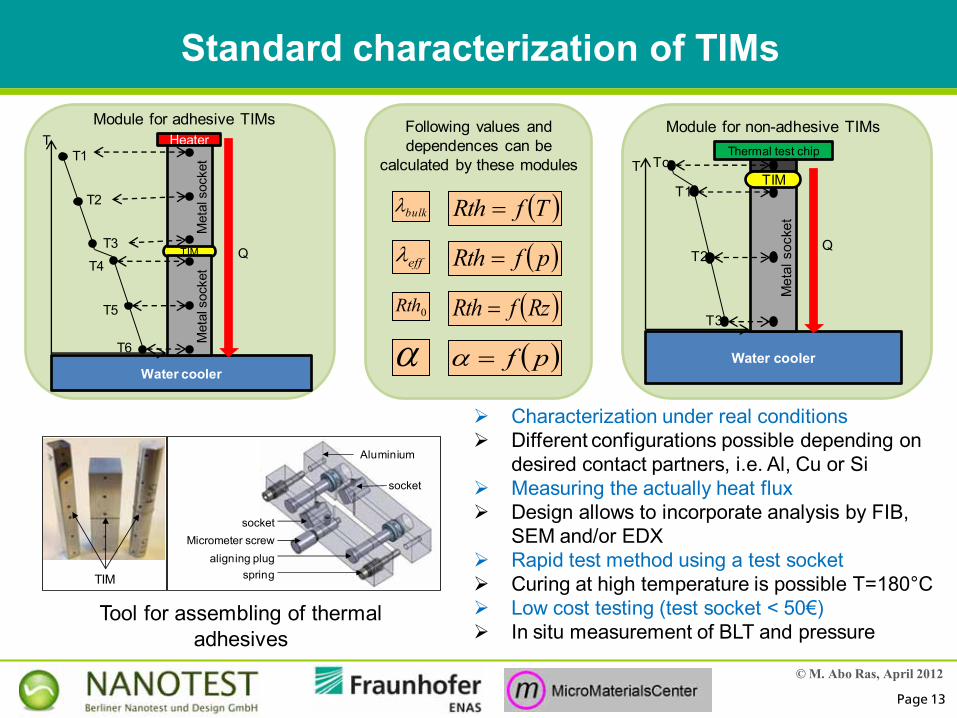
Standard characterization of TIMs
Characterization under real conditions Different configurations possible depending on
desired contact partners, i.e. Al, Cu or Si Measuring the actually heat flux Design allows to incorporate analysis by FIB,
SEM and/or EDX Rapid test method using a test socket Curing at high temperature is possible T=180°C Low cost testing (test socket < 50€) In situ measurement of BLT and pressure
bulk
RzfRth
pfRth
TfRth
eff
0Rth
Following values and dependences can be
calculated by these modules
pf
TIM
Water cooler
HeaterT
QT4
T5
T6
Met
al s
ocke
t
T1
T2
T3
Met
al s
ocke
t
TIM
aligning plug
socket
Micrometer screw
spring
socket
Aluminium
Tool for assembling of thermal adhesives
Water cooler
Thermal test chip
TIMT
Q
Tc
T1
T2
T3
Met
al s
ocke
t
Module for adhesive TIMs Module for non-adhesive TIMs
© M. Abo Ras, April 2012
Page 14
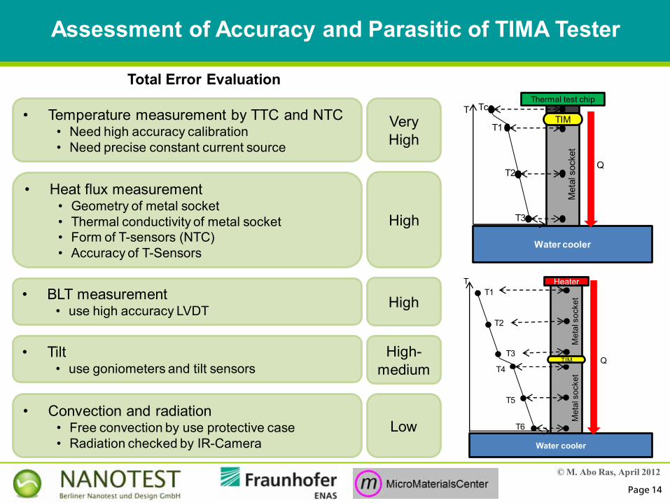
• Convection and radiation• Free convection by use protective case• Radiation checked by IR-Camera
• Tilt• use goniometers and tilt sensors
• Temperature measurement by TTC and NTC• Need high accuracy calibration• Need precise constant current source
• Heat flux measurement• Geometry of metal socket• Thermal conductivity of metal socket• Form of T-sensors (NTC)• Accuracy of T-Sensors
• BLT measurement • use high accuracy LVDT
Assessment of Accuracy and Parasitic of TIMA Tester
Water cooler
Thermal test chip
TIMT
Q
Tc
T1
T2
T3
Met
al s
ocke
t
Very High
High
High
High-medium
Low
TIM
Water cooler
HeaterT
QT4
T5
T6
Met
al s
ocke
t
T1
T2
T3
Met
al s
ocke
t
Total Error Evaluation
© M. Abo Ras, April 2012
Page 15
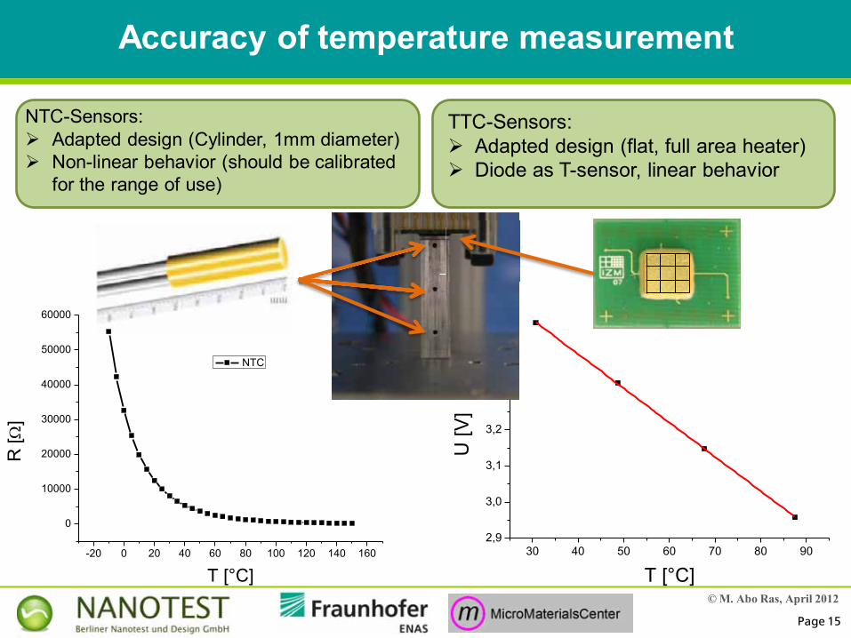
30 40 50 60 70 80 902,9
3,0
3,1
3,2
3,3
3,4
3,5
U [V
]
T [°C]-20 0 20 40 60 80 100 120 140 160
0
10000
20000
30000
40000
50000
60000
R [
]
T [°C]
NTC
Accuracy of temperature measurement
NTC-Sensors: Adapted design (Cylinder, 1mm diameter) Non-linear behavior (should be calibrated
for the range of use)
TTC-Sensors: Adapted design (flat, full area heater) Diode as T-sensor, linear behavior
© M. Abo Ras, April 2012
Page 16
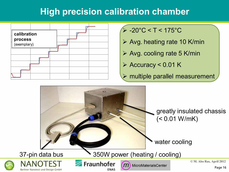
High precision calibration chamber
calibration process(exemplary)
-20°C < T < 175°C
Avg. heating rate 10 K/min
Avg. cooling rate 5 K/min
Accuracy < 0.01 K
multiple parallel measurement
water cooling
350W power (heating / cooling)37-pin data bus
greatly insulated chassis(< 0.01 W/mK)
© M. Abo Ras, April 2012
Page 17
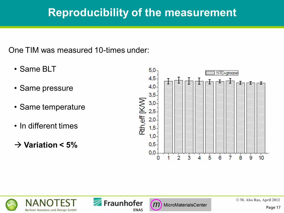
Reproducibility of the measurement
One TIM was measured 10-times under:
• Same BLT
• Same pressure
• Same temperature
• In different times
Variation < 5%

© M. Abo Ras, April 2012
Page 18
Interesting results measured by standard modules
What can be measured by these modules?
© M. Abo Ras, April 2012
Page 19
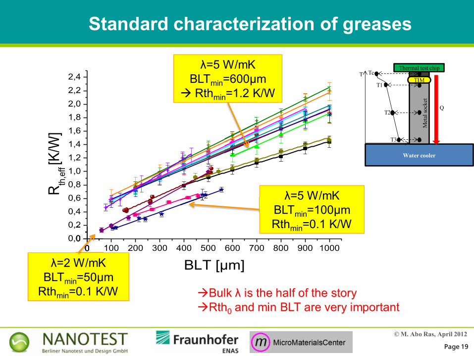
Standard characterization of greases
0 100 200 300 400 500 600 700 800 900 10000,00,20,40,60,81,01,21,41,61,82,02,22,4
R th,e
ff [K
/W]
BLT [µm]
λ=5 W/mKBLTmin=600µm Rthmin=1.2 K/W
λ=5 W/mKBLTmin=100µmRthmin=0.1 K/W
λ=2 W/mKBLTmin=50µm
Rthmin=0.1 K/W
00,00,2
Bulk λ is the half of the storyRth0 and min BLT are very important
Water cooler
Thermal test chip
TIMT
Q
Tc
T1
T2
T3
Met
al so
cket
© M. Abo Ras, April 2012
Page 20
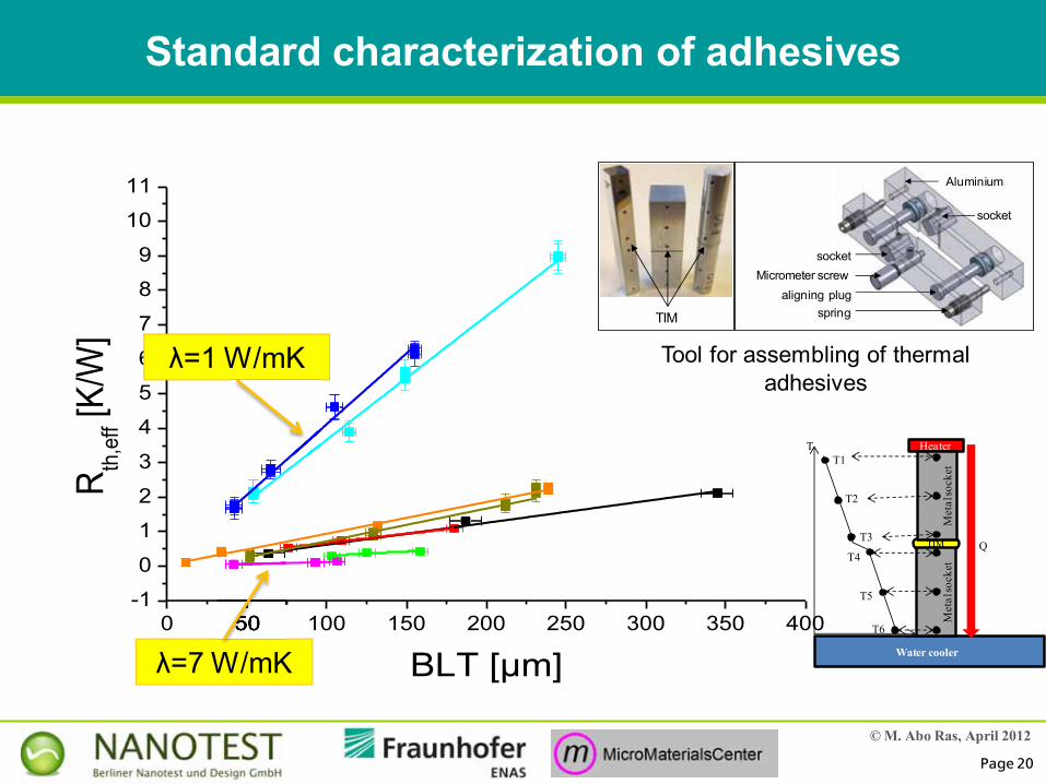
Standard characterization of adhesives
0 50 100 150 200 250 300 350 400-1
0
1
2
3
4
5
6
7
8
9
10
11
R th,e
ff [K/W
]
BLT [µm]λ=7 W/mK
λ=1 W/mK
50
TIM
Water cooler
HeaterT
QT4
T5
T6
Met
al so
cket
T1
T2
T3
Met
al so
cket
TIM
aligning plug
socket
Micrometer screw
spring
socket
Aluminium
Tool for assembling of thermal adhesives
© M. Abo Ras, April 2012
Page 21
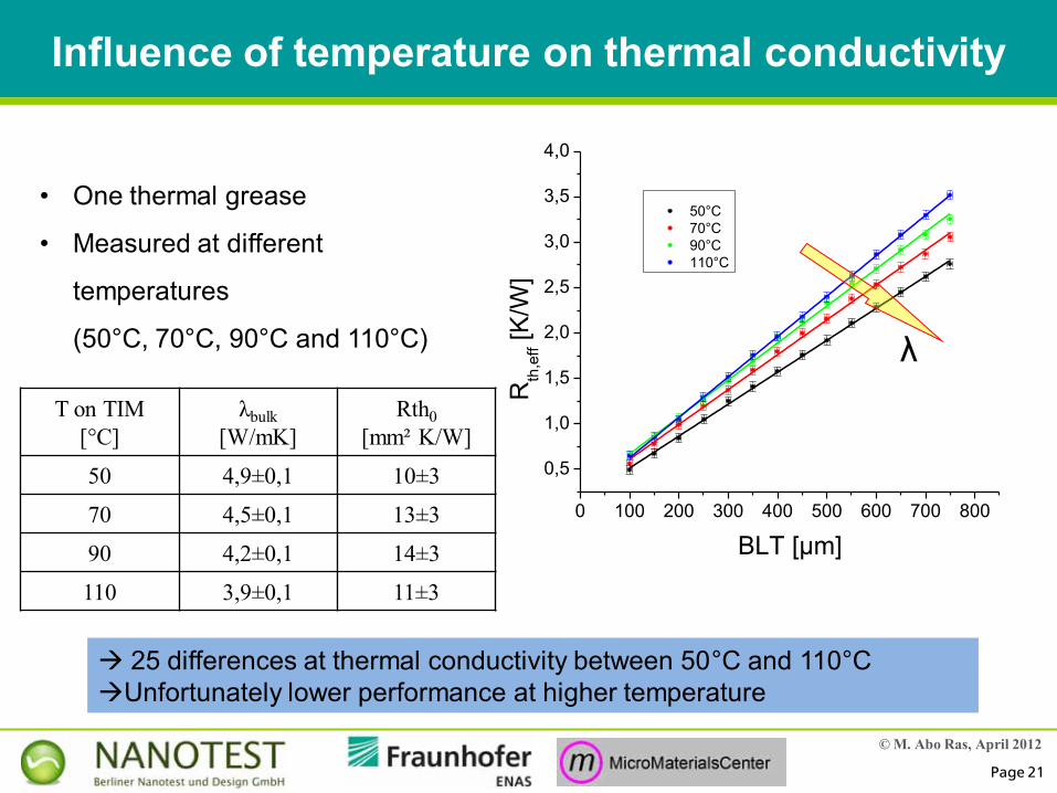
Influence of temperature on thermal conductivity
• One thermal grease
• Measured at different
temperatures
(50°C, 70°C, 90°C and 110°C)
0 100 200 300 400 500 600 700 800
0,5
1,0
1,5
2,0
2,5
3,0
3,5
4,0
50°C 70°C 90°C 110°C
Rth
,eff [K
/W]
BLT [µm]
T on TIM [°C]
λbulk[W/mK]
Rth0 [mm² K/W]
50 4,9±0,1 10±3
70 4,5±0,1 13±3
90 4,2±0,1 14±3
110 3,9±0,1 11±3
25 differences at thermal conductivity between 50°C and 110°CUnfortunately lower performance at higher temperature
λ
© M. Abo Ras, April 2012
Page 22
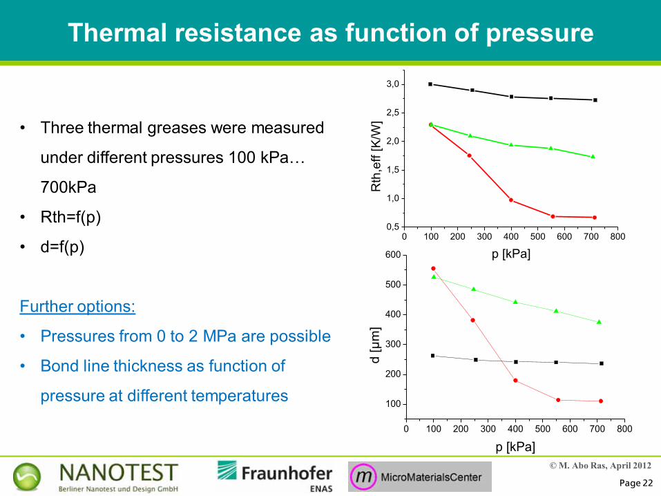
Thermal resistance as function of pressure
• Three thermal greases were measured
under different pressures 100 kPa…
700kPa
• Rth=f(p)
• d=f(p)
Further options:
• Pressures from 0 to 2 MPa are possible
• Bond line thickness as function of
pressure at different temperatures
0 100 200 300 400 500 600 700 8000,5
1,0
1,5
2,0
2,5
3,0
Rth
,eff
[K/W
]
p [kPa]
0 100 200 300 400 500 600 700 800
100
200
300
400
500
600
d [µ
m]
p [kPa]
© M. Abo Ras, April 2012
Page 23
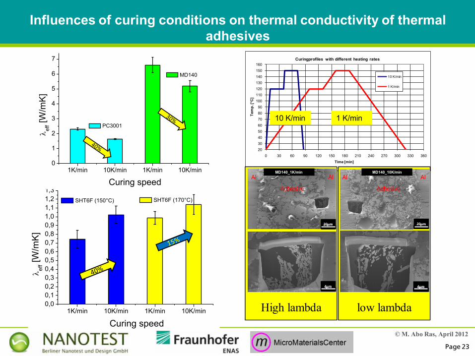
Influences of curing conditions on thermal conductivity of thermal adhesives
2030405060708090
100110120130140150160
0 30 60 90 120 150 180 210 240 270 300 330 360
Tem
p. [°
C]
Time [min]
Curingprofiles with different heating rates
10 K/min
1 K/min
10 K/min 1 K/min
1K/min 10K/min0,00,10,20,30,40,50,60,70,80,91,01,11,21,3
Curing speed
ef
f [W/m
K]
SHT6F (150°C)
1K/min 10K/min
SHT6F (170°C)
1K/min 10K/min0
1
2
3
4
5
6
7
Curing speed
ef
f [W/m
K]
PC3001
1K/min 10K/min
MD140
MD140_1K/minAlAl
Adhesive
AlAl
Adhesive
MD140_10K/min
20µm20µm
4µm4µm4µm4µm
20µm20µm
High lambda low lambda
© M. Abo Ras, April 2012
Page 24
Further module
accelerated in-situ measurement of reliability and aging behavior of thermal interface
materials
© M. Abo Ras, April 2012
Page 25
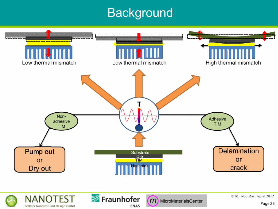
Background
Pump outor
Dry out
Non-adhesive
TIM
Pump out Delaminationor
crack
Adhesive TIM
Delamination
Ttime
ΔporΔd
Heat sinkTIMDie
Substrate
Low thermal mismatch Low thermal mismatch High thermal mismatch
© M. Abo Ras, April 2012
Page 26
timeΔRth
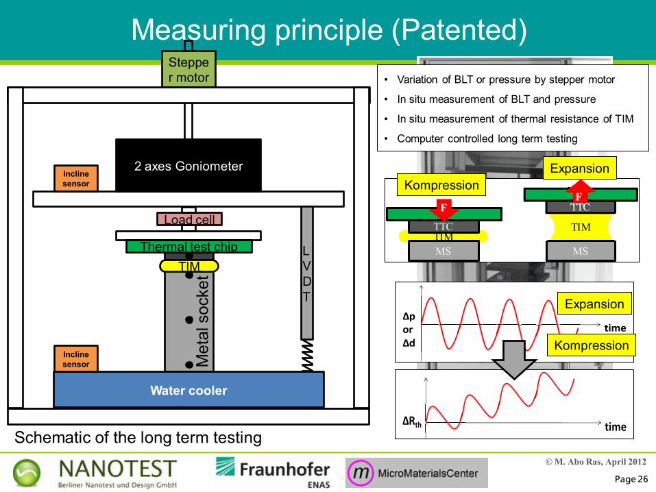
Measuring principle (Patented)• Variation of BLT or pressure by stepper motor
• In situ measurement of BLT and pressure
• In situ measurement of thermal resistance of TIM
• Computer controlled long term testing
Schematic of the long term testing
Thermal test chipTIM
Met
al s
ocke
t
2 axes Goniometer
LVDT
Load cell
Stepper motor
Inclinesensor
Water cooler
Inclinesensor
TIMTTC
MS
F
TIM
TTC
MS
TTC
ExpansionKompression
timeΔporΔd Kompression
Expansion

© M. Abo Ras, April 2012
Page 27
Further module
Characterization of highly conductive TIMs
© M. Abo Ras, April 2012
Page 28
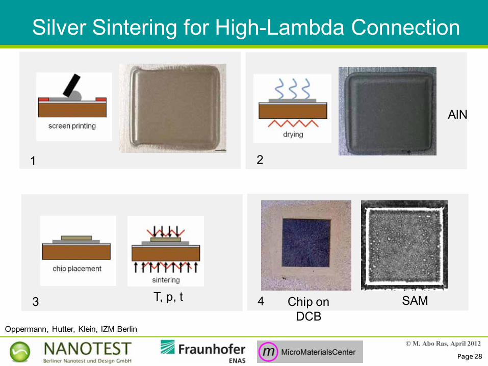
Silver Sintering for High-Lambda Connection
Chip on DCB
SAM
1 2
3 4
AlN
T, p, t
Oppermann, Hutter, Klein, IZM Berlin

© M. Abo Ras, April 2012
Page 29
Low T,p,t sintering
highly porous
High T,p,t sintering
continous µ-structure, grain formation
1 µm 1 µm
Sintered Plated
Microstructure of Silver - Die Bond, Sintered
Different process parameters (T, p, t) produce different microstructrures
Technology development necessaryOppermann, Hutter, Klein, IZM Berlin
© M. Abo Ras, April 2012
Page 30
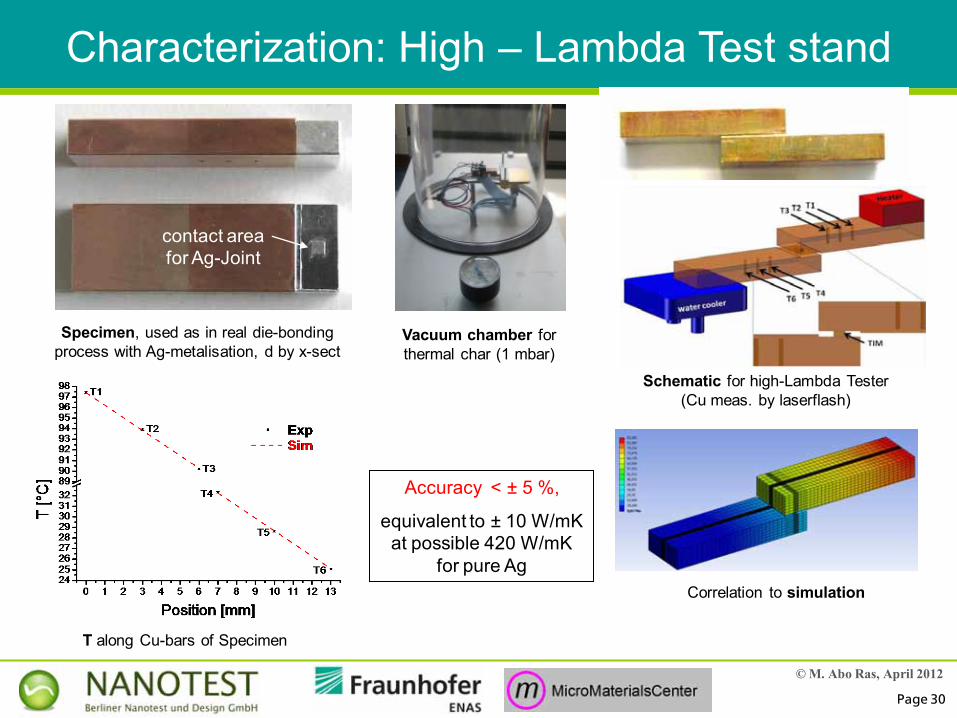
contact area for Ag-Joint
Characterization: High – Lambda Test stand
Specimen, used as in real die-bonding process with Ag-metalisation, d by x-sect
Vacuum chamber for thermal char (1 mbar)
Schematic for high-Lambda Tester(Cu meas. by laserflash)
Correlation to simulation
Accuracy < ± 5 %,
equivalent to ± 10 W/mK at possible 420 W/mK
for pure Ag
T along Cu-bars of Specimen
© M. Abo Ras, April 2012
Page 31
1µm1µm
Sample #1 @ 60N
Sample #4 @ 90N
Sample #5 @ 120N
1µm1µm
1µm1µm
Sample #1 @ 60N
Sample #4 @ 90N
Sample #5 @ 120N
10µm10µm
10µm10µm
10µm10µm
Sample #1 @ 60N
Sample #4 @ 90N
Sample #5 @ 120N
2µm2µm
2µm2µm
2µm2µm
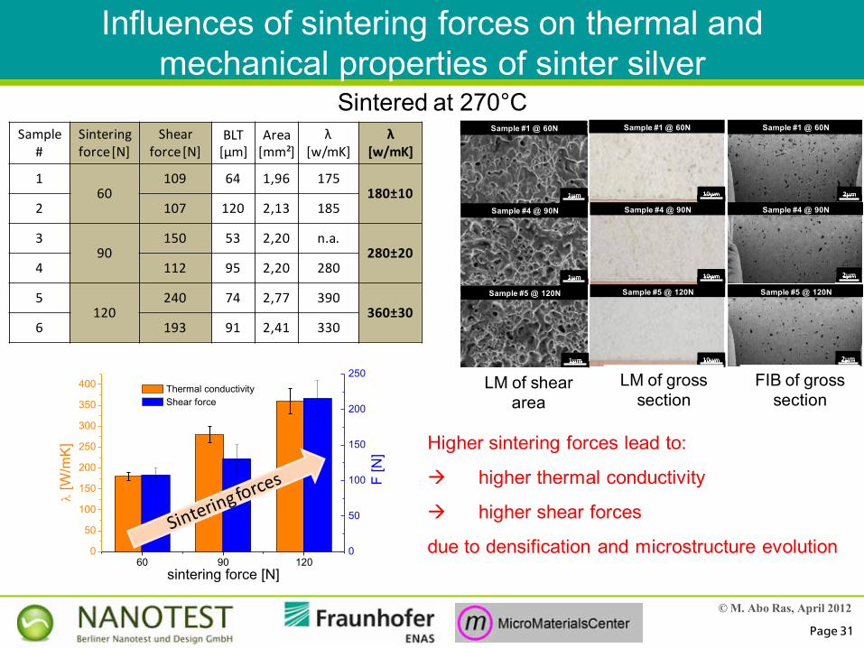
Sample#
Sinteringforce[N]
Shearforce[N]
BLT [µm]
Area[mm²]
λ[w/mK]
λ[w/mK]
160
109 64 1,96 175180±10
2 107 120 2,13 185
390
150 53 2,20 n.a.280±20
4 112 95 2,20 280
5120
240 74 2,77 390360±30
6 193 91 2,41 330
60 90 1200
50
100
150
200
250
300
350
400 Thermal conductivity
[W
/mK
]
sintering force [N]
0
50
100
150
200
250 F
[N]
Shear force
Sintered at 270°C
LM of shear area
LM of gross section
FIB of gross section
Higher sintering forces lead to:
higher thermal conductivity
higher shear forces
due to densification and microstructure evolution
Influences of sintering forces on thermal and mechanical properties of sinter silver
© M. Abo Ras, April 2012
Page 32
Further module
High Accuracy Characterization Module
Characterization of small effectse.g. surface modification by
nanotechnologies
© M. Abo Ras, April 2012
Page 33
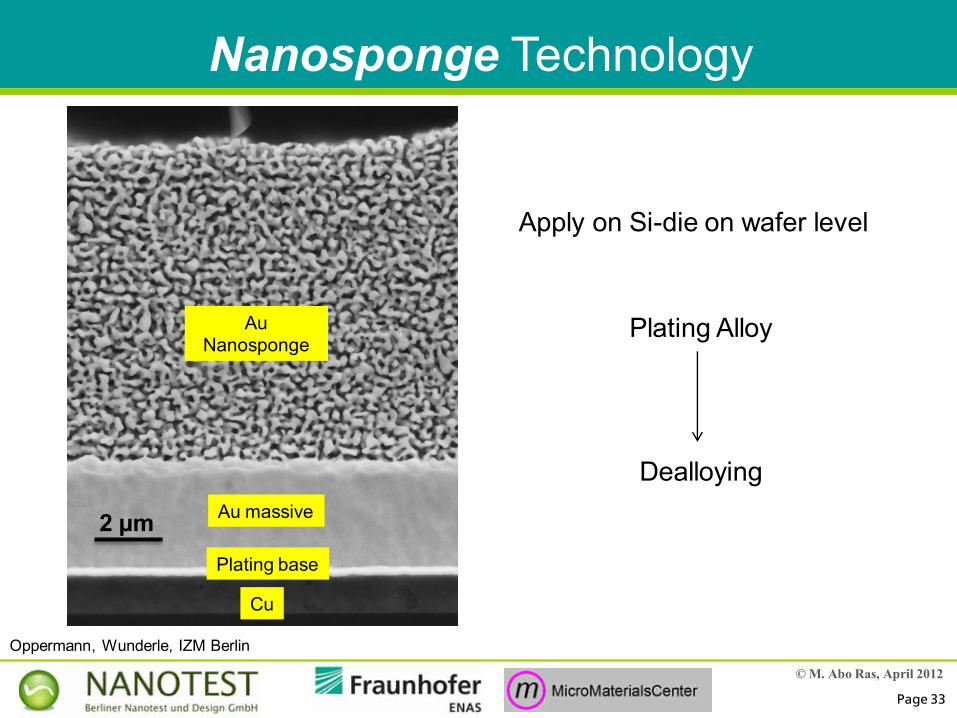
2 µm
Au Nanosponge
Nanosponge Technology
Plating Alloy
Dealloying
Apply on Si-die on wafer level
Au massive
Plating base
Cu
Oppermann, Wunderle, IZM Berlin
© M. Abo Ras, April 2012
Page 34
300 nm
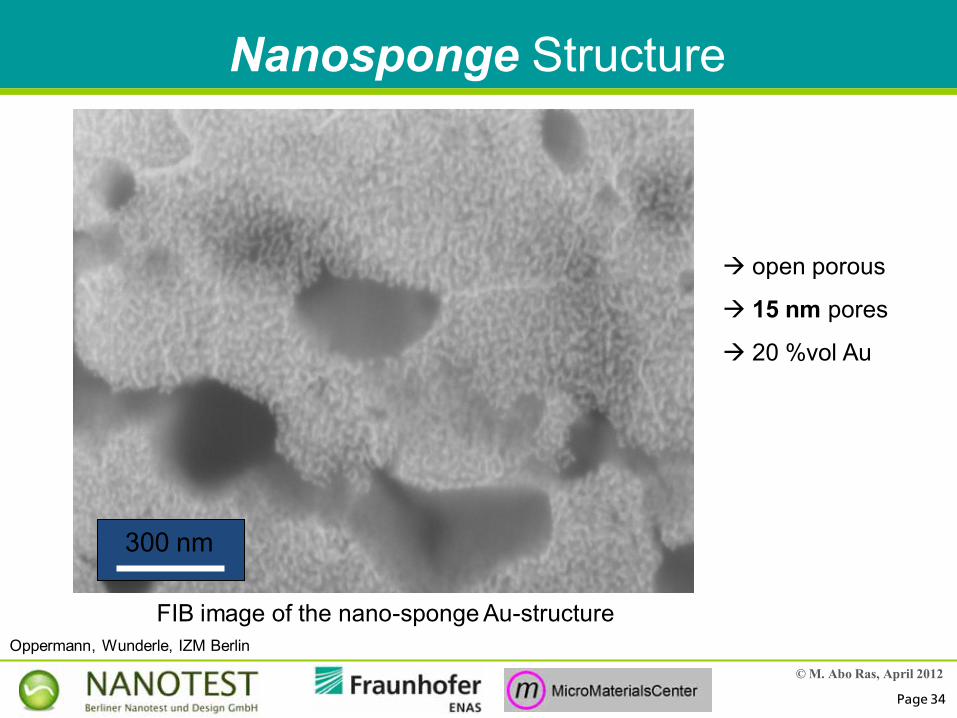
Nanosponge Structure
open porous
15 nm pores
20 %vol Au
FIB image of the nano-sponge Au-structureOppermann, Wunderle, IZM Berlin
© M. Abo Ras, April 2012
Page 35
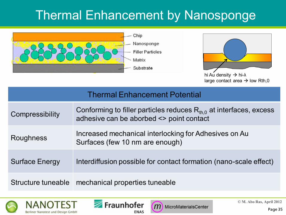
Thermal Enhancement by Nanosponge
Thermal Enhancement Potential
Compressibility Conforming to filler particles reduces Rth,0 at interfaces, excessadhesive can be aborbed <> point contact
Roughness Increased mechanical interlocking for Adhesives on Au Surfaces (few 10 nm are enough)
Surface Energy Interdiffusion possible for contact formation (nano-scale effect)
Structure tuneable mechanical properties tuneable
hi Au density hi-λlarge contact area low Rth,0
© M. Abo Ras, April 2012
Page 36
TIM
Si
Si
Micro water cooler
Thin film heater
Equipotential surfacesT-Sensors
CVD Ox
F
AlN- substrate
Wire-bond bumps
AlN- substrate
Ceramic Substrate
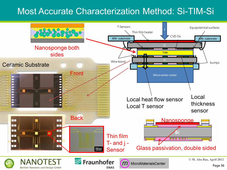
Most Accurate Characterization Method: Si-TIM-Si
Nanosponge both sides
Back
Local heat flow sensorLocal T sensor
Thin film T- and j -Sensor
Local thickness sensor
Front
Glass passivation, double sided
Nanosponge
© M. Abo Ras, April 2012
Page 37
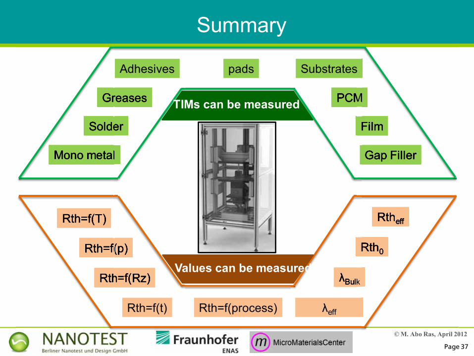
Summary
Rth=f(Rz)
Rth=f(p)
Rth=f(T) Rtheff
Rth0
λBulk
λeff
λBulk
Rtheff
Rth0
Rth=f(Rz)
=f(p)
Rth
Rth=f(p)
Rth=f(T)
Rth=f(t) Rth=f(process)
Values can be measured
Greases
padsAdhesives Substrates
PCM
Film
Gap Filler
Solder
Mono metal
PCMPCM
Film
Gap Filler
Greases
Solder
Greases
Solder
Mono metal
TIMs can be measured

© M. Abo Ras, April 2012
Page 38
Thank you very much for your attention!
Time for questions?
Some of this work was carried out within the BMBF Project “CharTIM”
This funding is gratefully acknowledged
Contact: [email protected]