test van for maintenance and diagnostics - microsoft · pdf filemegger transformer test van...
TRANSCRIPT
Megger Transformer Test Van
Test van for maintenance and diagnostics
of power transformers
Routine and advanced diagnostic tests
Centralized control and reporting
Two sets of cables (HV&LV) are shared among different instruments
Automated test circuit arrangement and switching process
Safe operation and user guidance through the tests
Easy extraction of mounted instruments for standalone use
1
2
3
4
5
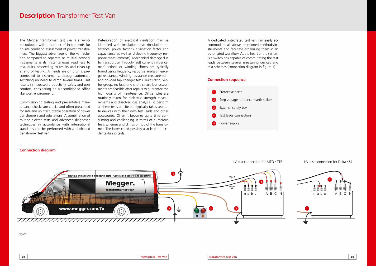
Protective earth
Step voltage reference (earth spike)
External safety box
Test leads connection
Power supply
1 12 3
5
44
LV test connection for MTO / TTR HV test connection for Delta / S1
Description Transformer Test Van
02 Transformer Test Van Transformer Test Van 03
The Megger transformer test van is a vehic-le equipped with a number of instruments for on-site condition assessment of power transfor-mers. The biggest advantage of the van solu-tion compared to separate or multi-functional instruments is its instantaneous readiness to test, quick proceeding to results and clean up at end of testing. All leads are on drums, pre-connected to instruments, through automatic switching no need to climb several times. This results in increased productivity, safety and user comfort, considering an air-conditioned office like work environment.
Commissioning testing and preventative main-tenance checks are crucial and often prescribed for safe and uninterruptable operation of power transformers and substations. A combination of routine electric tests and advanced diagnostic techniques in accordance with international standards can be performed with a dedicated transformer test van.
Deterioration of electrical insulation may be identified with insulation tests (insulation re-sistance, power factor / dissipation factor and capacitance as well as dielectric frequency res-ponse measurements). Mechanical damage due to transport or through-fault current influence, malfunctions or winding shorts are typically found using frequency response analysis, leaka-ge reactance, winding resistance measurement and on-load tap changer tests. Turns ratio, vec-tor group, no-load and short-circuit loss assess-ments are feasible after repairs to guarantee the high quality of maintenance. Oil samples are routinely taken for dielectric strength measu-rements and dissolved gas analysis. To perform all these tests on-site one typically takes separa-te devices with their own test leads and other accessories. Often it becomes quite time con-suming and challenging in terms of numerous tests schemes and climbs on top of the transfor-mer. The latter could possibly also lead to acci-dents during tests.
A dedicated, integrated test van can easily ac-commodate all above mentioned methods/in-struments and facilitate organizing them in an automated workflow. At the heart of the system is a switch box capable of commutating the test leads between several measuring devices and test schemes (connection diagram in figure 1).
Connection diagram
Figure 1
Connection sequence
A
B
C
D
E
F
Features Transformer Test Van
Features 05
2
3
4
5
1
6
7
1
2
3
4
5
6
7
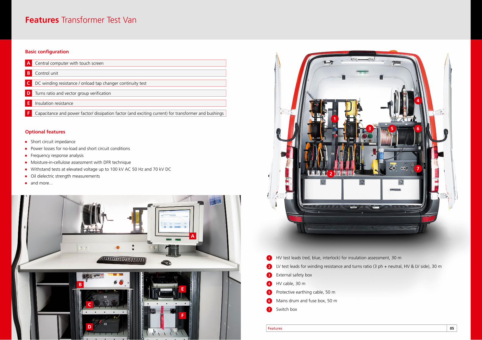
HV test leads (red, blue, interlock) for insulation assessment, 30 m
LV test leads for winding resistance and turns ratio (3 ph + neutral, HV & LV side), 30 m
External safety box
HV cable, 30 m
Protective earthing cable, 50 m
Mains drum and fuse box, 50 m
Switch box
Basic configuration
Short circuit impedance
Power losses for no-load and short circuit conditions
Frequency response analysis
Moisture-in-cellulose assessment with DFR technique
Withstand tests at elevated voltage up to 100 kV AC 50 Hz and 70 kV DC
Oil dielectric strength measurements
and more...
Optional features
Central computer with touch screenA
Control unitB
DC winding resistance / onload tap changer continuity testC
Turns ratio and vector group verificationD
Insulation resistanceE
Capacitance and power factor/ dissipation factor (and exciting current) for transformer and bushingsF
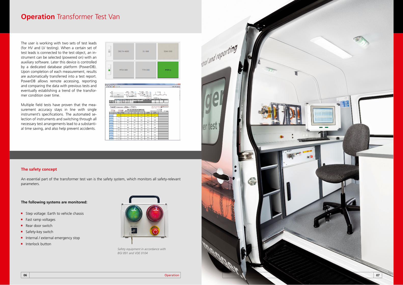
The safety concept
An essential part of the transformer test van is the safety system, which monitors all safety-relevant parameters.
The following systems are monitored:
Step voltage: Earth to vehicle chassis
Fast ramp voltages
Rear door switch
Safety-key switch
Internal / external emergency stop
Interlock buttonSafety equipment in accordance with BGI 891 and VDE 0104
Operation Transformer Test Van
06 Operation 07
The user is working with two sets of test leads (for HV and LV testing). When a certain set of test leads is connected to the test object, an in-strument can be selected (powered on) with an auxiliary software. Later this device is controlled by a dedicated database platform (PowerDB). Upon completion of each measurement, results are automatically transferred into a test report. PowerDB allows remote accessing, reporting and comparing the data with previous tests and eventually establishing a trend of the transfor-mer condition over time. Multiple field tests have proven that the mea-surement accuracy stays in line with single instrument’s specifications. The automated se-lection of instruments and switching through all necessary test arrangements lead to a substanti-al time saving, and also help prevent accidents.
SebaKMT · Dr.-Herbert-Iann-Str. 6 · D-96148 BaunachTel. +49(0)9544 - 680 · Fax +49(0)9544 - [email protected] · www.sebakmt.com
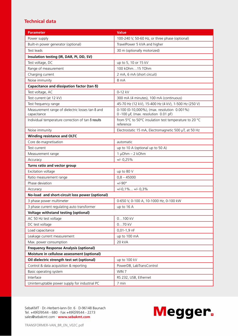
Parameter Value
Power supply 100-240 V, 50-60 Hz, or three phase (optional)
Built-in power generator (optional) TravelPower 5 kVA and higher
Test leads 30 m (optionally motorized)
Insulation testing (IR, DAR, PI, DD, SV)
Test voltage, DC up to 5, 10 or 15 kV
Range of measurement 100 kOhm…15 TOhm
Charging current 2 mA, 6 mA (short circuit)
Noise immunity 8 mA
Capacitance and dissipation factor (tan δ)
Test voltage, AC 0-12 kV
Test current (at 12 kV) 300 mA (4 minutes), 100 mA (continuous)
Test frequency range 45-70 Hz (12 kV), 15-400 Hz (4 kV), 1-500 Hz (250 V)
Measurement range of dielectric losses tan δ and capacitance
0-100 (0-10,000%), (max. resolution 0.001%) 0 -100 μF, (max. resolution 0.01 pF)
Individual temperature correction of tan δ results from 5°C to 50°C insulation test temperature to 20 °C reference
Noise immunity Electrostatic 15 mA, Electromagnetic 500 μT, at 50 Hz
Winding resistance and OLTC
Core de-magnetisation automatic
Test current up to 10 A (optional up to 50 A)
Measurement range 1 µOhm – 2 kOhm
Accuracy +/- 0,25%
Turns ratio and vector group
Excitation voltage up to 80 V
Ratio measurement range 0,8 – 45000
Phase deviation +/-90°
Accuracy +/-0,1%... +/- 0,3%
No-load and short-circuit loss power (optional)
3 phase power multimeter 0-650 V, 0-100 A, 10-1000 Hz, 0-100 kW
3 phase current regulating auto transformer up to 16 A
Voltage withstand testing (optional)
AC 50 Hz test voltage 0…100 kV
DC test voltage 0…70 kV
Load capacitance 0,01-1,9 nF
Leakage current measurement up to 100 mA
Max. power consumption 20 kVA
Frequency Response Analysis (optional)
Moisture in cellulose assessment (optional)
Oil dielectric strength test set (optional) up to 100 kV
Control & data acquisition & reporting PowerDB, LabTransControl
Basic operating system WIN 7
Interface RS 232, USB, Ethernet
Uninterruptable power supply for industrial PC 7 min
Technical data
TRANSFORMER-VAN_BR_EN_V02C.pdf