testamerica canton sop amendment form · sop title: inductively coupled plasma – atomic emission...
TRANSCRIPT

TestAmerica Canton
SOP Amendment Form SOP NUMBER: NC-MT-012 Rev. 5
SOP TITLE: Inductively Coupled Plasma – Atomic Emission Spectroscopy, Spectrometric Method for Element Analyses
REASON FOR ADDITION OR CHANGE: Added ICS wording for Wisconsin samples
CHANGE EFFECTIVE FROM: (DATE): 6/29/16
Change(s) Made: Added the following to section 10:
10.5.5. When Wisconsin samples are analyzed, the following additional ICS’s will be performed with each run:
ICS Interferents ICS-B As ICS-C Al ICS-D Co ICS-E Fe ICS-F Ti ICS-G V ICS-H Cr ICS-I Cu
ICS Interferents ICS-J Mn ICS-K Ni ICS-L Si ICS-M Mo
10.5.6. Each ICS will be evaluated for all target compounds reported not run as interferents to see if their concentrations (absolute value of the concentration) are less than their WI LOQ.
10.5.7. If the concentration of the ICS for all target compounds not run as interferents is less than the WI LOQ, the data is acceptable as is.
10.5.8. If the concentration in the ICS for all target compounds not run as interferents is greater than the WI LOQ, then either new IECs must be generated so that the interferent affect is less than the WI LOQ, or the sample results will be qualified accordingly for the interference. EDITED BY/DATE: Melissa Fuller-Gustavel 29 June 2016
TestAmerica Canton
SOP Amendment Form SOP NUMBER: NC-MT-012 Rev. 5
SOP TITLE: Inductively Coupled Plasma – Atomic Emission Spectroscopy, Spectrometric Method for Element Analyses
REASON FOR ADDITION OR CHANGE: Remove references to DoD
CHANGE EFFECTIVE FROM: (DATE): 6/15/16
Change(s) Made:
Removed references to DoD/QSM.
EDITED BY/DATE: Melissa Fuller-Gustavel 6/15/16

TestAmerica Canton
SOP No. NC-MT-012, Rev. 5 Effective Date: 04/30/15
Page 1 of 33
Facility Distribution No. ___________ Distributed To:_______________________ The controlled copies of this SOP are the PDF copy of the SOP that is posted to the laboratory’s SOP Directory and, where applicable, the SOP that is printed and placed in the General Chemistry SOP binder. Printed or electronic copies of this SOP distributed outside of the facility are considered uncontrolled.
Company Confidential and Proprietary
Title: INDUCTIVELY COUPLED PLASMA – ATOMIC EMISSION SPECTROSCOPY, SPECTROMETRIC METHOD FOR ELEMENT
ANALYSES
[Methods: SW846 Methods 6010B, 6010C, and EPA Method 200.7]
Approvals (Signature/Date):
____________________________04/30/15_ ___________________________03/06/15 _ Technology Specialist Date Health & Safety Coordinator Date
___________________________03/06/15__ ___________________________03/13/15 _ Quality Assurance Manager Date Technical Director Date
This SOP was previously identified as SOP NC-MT-012, Rev 4, dated 09/13/13
Copyright Information:
This documentation has been prepared by TestAmerica Analytical Testing Corp. and its affiliates (“TestAmerica”), solely for their own use and the use of their customers in evaluating their qualifications and capabilities in connection with a particular project. The user of this document agrees by its acceptance to return it to TestAmerica upon request and not to reproduce, copy, lend, or otherwise disclose its contents, directly or indirectly, and not to use if for any other purpose other than that for which it was specifically provided. The user also agrees that where consultants or other outside parties are involved in the evaluation process, access to these documents shall not be given to said parties unless those parties also specifically agree to these conditions.
THIS DOCUMENT CONTAINS VALUABLE CONFIDENTIAL AND PROPRIETARY INFORMATION. DISCLOSURE, USE OR REPRODUCTION OF THESE MATERIALS WITHOUT THE WRITTEN AUTHORIZATION OF TESTAMERICA IS STRICTLY PROHIBITED. THIS UNPUBLISHED WORK BY TESTAMERICA IS PROTECTED BY STATE AND FEDERAL LAW OF THE UNITED STATES. IF PUBLICATION OF THIS WORK SHOULD OCCUR, THE FOLLOWING NOTICE SHALL APPLY: ©COPYRIGHT 2015 TESTAMERICA ANALYTICAL TESTING CORP. ALL RIGHTS RESERVED.

SOP No. NC-MT-012, Rev. 2 Effective Date: 04/30/15 Page 2 of 33
Company Confidential and Proprietary
TABLE OF CONTENTS
1. Scope And Application .......................... ................................................................................ 3
2. Summary Of Method .............................. ................................................................................ 3
3. Definitions .................................... .......................................................................................... 4
4. Interferences................................... ........................................................................................ 4
5. Safety ......................................... ............................................................................................. 5
6. Equipment And Supplies ......................... .............................................................................. 6
7. Reagents And Standards ......................... .............................................................................. 6
8. Sample Collection, Preservation And Storage .... ................................................................. 7
9. Quality Control ................................ ....................................................................................... 7
10. Calibration And Standardization ............... .......................................................................... 13
11. Procedure ..................................... ........................................................................................ 16
12 Data Analysis And Calculations ................. ......................................................................... 19
13. Method Performance …………………………………………………………………… ..…....… 22
14. Pollution Prevention .......................... .................................................................................. 22
15. Waste Management …………………………….………….……………...….. .……………...…...22
16. References .................................... ........................................................................................ 23
17. Miscellaneous (Tables, Appendices, Etc.) ...... .................................................................... 24
LIST OF APPENDICES: APPENDIX A - Tables
APPENDIX B - Cross Reference of Terms Used In Metho ds and SOP
APPENDIX C - Troubleshooting Guide
APPENDIX D - Contamination Control Guidelines
APPENDIX E - Preventative Maintenance

SOP No. NC-MT-012, Rev. 2 Effective Date: 04/30/15 Page 3 of 33
Company Confidential and Proprietary
1. SCOPE AND APPLICATION
1.1. This procedure describes the analysis of elements including metals in solution by Inductively Coupled Plasma-Atomic Emission Spectroscopy (ICP-AES) using SW-846 Methods 6010B, 6010C, and EPA Method 200.7. Table I of Appendix A lists the elements appropriate for analysis by Methods, 6010B, 6010C, and 200.7. Additional elements may be analyzed under these methods provided that the method performance criteria presented in Section 13.0 are met.
1.2. ICP analysis provides for the determination of metal concentrations over several orders of magnitude. Detection limits, sensitivity, and optimum concentration ranges of the metals will vary with the matrices and instrumentation used.
1.3. Methods 6010B and 6010C are applicable to the determination of dissolved, suspended, total recoverable, and total elements in ground water, aqueous samples, soils, sludges, wastes, sediments, biological, and TCLP, EP, and other leachates/extracts. All matrices require digestion prior to analysis. Silver concentrations greater than 2.0 mg/L in aqueous samples and 100 mg/kg in solid matrix samples may be subject to error. Precipitation may occur in samples where silver concentrations exceed these levels, leading to the generation of erroneous data.
1.4. Method 200.7 is applicable to the determination of dissolved, suspended, total recoverable, and total elements in water, waste water, and solid wastes. All matrices require digestion prior to analysis. Silver concentrations must be below 0.1 mg/L in aqueous samples for the reasons discussed above. .
2. SUMMARY OF METHOD
2.1. This method describes a technique for the determination of multiple elements in solution using sequential or simultaneous optical systems and axial or radial viewing of the plasma. The basis of the method is the measurement of atomic emission by an optical spectroscopic technique. Samples are nebulized and the aerosol that is produced is transported to the plasma torch where excitation occurs. Characteristic atomic-line emission spectra are produced by radio frequency inductively-coupled plasma (ICP). The spectra are dispersed by a grating spectrometer and the intensities of the emission lines are monitored by photomultiplier tubes. The amplified photocurrents from the photomultiplier tubes are processed and controlled by a computer system. A background correction technique is required to compensate for variable background contribution to the determination of elements. Background must be measured adjacent to analyte lines during analysis. The position selected for the background intensity measurement, on either or both sides of the analytical line, will be determined by the complexity of the spectrum adjacent to the analyte line. The position used for background determination must be free of spectral interferences and reflect the same change in background intensity as occurs at the analyte wavelength measured. Background correction is not required in cases of line broadening where a background correction measurement would actually degrade the analytical result. The possibility of additional interferences must also be recognized and appropriate actions taken. Alternatively, multivariate
SOP No. NC-MT-012, Rev. 2 Effective Date: 04/30/15 Page 4 of 33
Company Confidential and Proprietary
calibration methods may be chosen, for which point selection for background correction is superfluous, since in this mode whole spectral regions are processed instead of single lines.
2.2. Refer to NC-IP-010, Acid Digestion of Soils by SW846 Method 3050B, and NC-IP-011, Acid Digestion of Aqueous Samples by SW846 and MCAWW 200 Series Methods, for details on sample preparation methods.
3. DEFINITIONS
3.1. Refer to the glossary in the TestAmerica Canton Quality Assurance Manual (QAM), current version for additional definitions. Refer to Appendix B for a cross reference of method definitions.
4. INTERFERENCES
4.1. Physical, chemical, and spectral interference effects may contribute to inaccuracies in the determinations of elements by ICP. Spectral interferences are caused by:
• Overlap of a spectral line from another element.
• Unresolved overlap of molecular band spectra.
• Background contribution from continuous or recombination phenomena.
• Stray light from the line emission of high concentration elements.
4.1.1. A background correction technique is required to compensate for variable background contribution to the determination of elements. Background correction is not required in cases where a background correction would actually degrade the analytical result.
4.1.2. Inter-element correction factors (IECs) are necessary to compensate for spectral overlap. Inter-element interferences occur when elements in the sample emit radiation at wavelengths so close to that of another analyte that they contribute significant intensity to the analyte channel. If such conditions exist, the intensity contributed by the matrix elements will cause an excessively high (or sometimes low) concentration to be reported for the analyte. Inter-element corrections IECs must be applied to the analyte to remove the effects of these unwanted emissions.
4.1.3. Physical interferences are generally considered to be effects associated with sample transport, nebulization, and conversion within the plasma. These interferences may result in differences between instrument responses for the sample and the calibration standards. Physical interferences may occur in the transfer of solution to the nebulizer (e.g., viscosity effects), at the point of aerosol formation and transport to the plasma (e.g., surface tension), or during excitation and ionization processes within the plasma itself. Changes in viscosity and surface tension can cause significant inaccuracies, especially in samples containing high dissolved solids or high acid concentrations. If

SOP No. NC-MT-012, Rev. 2 Effective Date: 04/30/15 Page 5 of 33
Company Confidential and Proprietary
physical interferences are present, dilution of the sample, use of a peristaltic pump or mass flow controller, use of an internal standard, and/or use of a high solids nebulizer can reduce the effect. Chemical interferences are characterized by molecular compound formation, ionization effects, and solute vaporization effects.
5. SAFETY
5.1. Employees must abide by the policies and procedures in the Corporate Environmental Health and Safety Manual, the Facility Addendum to the Corporate EH&S Manual, and this document.
5.2. Eye protection that protects against splash, laboratory coat, and appropriate gloves must be worn while samples, standards, solvents, and reagents are being handled. Disposable gloves that have been contaminated must be removed and discarded; other gloves must be cleaned immediately.
5.3. The following is a list of the materials used in this method, which have a serious or significant hazard rating. NOTE: This list does not include all materials used in the method. The table contains a summary of the primary hazards listed in the Safety Data Sheet (SDS) for each of the materials listed in the table. A complete list of materials used in the method can be found in the Reagents and Standards section. Employees must review the information in the SDS for each material before using it for the first time or when there are major changes to the SDS.
Material (1) Hazards Exposure Limit (2) Signs and symptoms of exposure
Nitric Acid Corrosive Oxidizer Poison
2 ppm-TWA 4-ppm STEL
Nitric acid is extremely hazardous; it is corrosive, reactive, an oxidizer, and a poison. Inhalation of vapors can cause breathing difficulties and lead to pneumonia and pulmonary edema, which may be fatal. Other symptoms may include coughing, choking, and irritation of the nose, throat, and respiratory tract. Can cause redness, pain, and severe skin burns. Concentrated solutions cause deep ulcers and stain skin a yellow or yellow-brown color. Vapors are irritating and may cause damage to the eyes. Contact may cause severe burns and permanent eye damage.
Hydrochloric Acid
Corrosive Poison
5 ppm-Ceiling
Inhalation of vapors can cause coughing, choking, inflammation of the nose, throat, and upper respiratory tract, and in severe cases, pulmonary edema, circulatory failure, and death. Can cause redness, pain, and severe skin burns. Vapors are irritating and may cause damage to the eyes. Contact may cause severe burns and permanent eye damage.
1 – Always add acid to water to prevent violent reactions
2 – Exposure limit refers to the OSHA regulatory exposure limit.

SOP No. NC-MT-012, Rev. 2 Effective Date: 04/30/15 Page 6 of 33
Company Confidential and Proprietary
5.3.1. The plasma emits strong UV light and is harmful to vision. NOTE: AVOID looking directly at the plasma .
5.3.2. The RF generator produces strong radio frequency waves, most of which are unshielded. People with pacemakers must not go near the instrument while in operation.
5.4. Exposure to chemicals must be maintained as low as reasonably achievable. All samples with stickers that read “Caution/Use Hood!” must be opened in the hood. Contact the EH&S Coordinator if this is not possible. Metals digestates can be processed outside of a fume hood. Solvent and waste containers must be kept closed unless transfers are being made.
5.5. All work must be stopped in the event of a known or potential compromise to the health and safety of a TestAmerica Canton associate. The situation must be reported immediately to the EH&S Coordinator and the Laboratory Supervisor.
6. EQUIPMENT AND SUPPLIES
6.1. Inductively Coupled Plasma Atomic Emission Spectrometer equipped with autosampler and background correction.
6.2. Radio Frequency Generator
6.3. Argon gas supply, welding grade or equivalent
6.4. Coolflow or appropriate water cooling device
6.5. Peristaltic Pump
6.6. Calibrated automatic pipettes or Class A glass volumetric pipettes – ranging from 5 µL to 10 ml
6.7. Class A volumetric flasks – range from 50 ml -to 2000 ml
6.8. Autosampler tubes
7. REAGENTS AND STANDARDS
7.1. Intermediate standards are purchased as custom multi-element mixes or as single-element solutions. All standards must be stored in FEP fluorocarbon or unused polyethylene or polypropylene bottles. Intermediate standard solutions must be replaced prior to the expiration date provided by the manufacturer. If no expiration date is provided, the intermediate solutions may be used for up to one year. They must be replaced sooner if verification from an independent source indicates a problem. Expiration dates can be extended, provided that the acceptance criteria described in laboratory-specific SOPs are met. Additional information can be found

SOP No. NC-MT-012, Rev. 2 Effective Date: 04/30/15 Page 7 of 33
Company Confidential and Proprietary
in SOP NC-QA-017. Standard or spiking concentrations, as well as vendors, are subject to change.
7.2. Working calibration, calibration verification solutions, and internal standard solutions must be prepared in a matrix of 5% hydrochloric and 5% nitric acids. Refer to Tables II, III, and IV (Appendix A) for details regarding the working standard concentrations for calibration, calibration verification, interference correction, and spiking solutions. Refer to the reagents module in LIMS for details on standard or reagent preparation.
7.3. Concentrated nitric acid (HNO3), trace metal grade or better.
7.4. Concentrated hydrochloric acid (HCl), trace metal grade or better.
7.5. Reagent water must be produced by a Millipore DI system or equivalent. Reagent water must be free of the analytes of interest as demonstrated through the analysis of method blanks.
8. SAMPLE COLLECTION, PRESERVATION AND STORAGE
8.1. Sample holding times for metals are six months from time of collection to the time of analysis.
8.2. Aqueous samples are preserved with nitric acid to a pH of <2 and may be stored in either plastic or glass. If boron is to be determined, plastic containers are preferred. Refrigeration is not required. Preservation must be verified prior to analysis.
8.3. Soil samples do not require preservation, but must be stored at 4°C ± 2° until the time of preparation.
8.4. Metals samples that are preserved at the laboratory must be held for 24 hours before digestion. Note: If the samples are preserved the same day of collection, the 24-hour waiting period is not required
9. QUALITY CONTROL
9.1. Initial Demonstration of Capability
9.1.1. Prior to analysis of any analyte using Methods 200.7, 6010B, or 6010C, the following requirements must be met.
9.1.2. Instrument Detection Limits (IDLs):
9.1.3. IDLs are useful means to evaluate the instrument noise level and response changes over time for each analyte from a series of reagent blank analyses to obtain a calculated concentration. They are not to be confused with the lower limit of quantitation, nor should they be used in establishing this limit. It

SOP No. NC-MT-012, Rev. 2 Effective Date: 04/30/15 Page 8 of 33
Company Confidential and Proprietary
may be helpful to compare the calculated IDLs to the established lower limit of quantitation; however, it should be understood that the lower limit of quantitation needs to be verified using the criteria in Section 10.7.
9.1.4. Instrument Detection Limit (IDL),
9.1.5. The IDL for each wavelength used for detection for each analyte must be determined for each instrument. The IDL must be determined annually. Whenever the instrument is adjusted in any way that may affect the IDL, the IDL for that instrument must be re-determined. The IDL will be determined by multiplying the standard deviation obtained from the analysis of seven consecutive measurements of a blank solution, by three. Each measurement must be performed as though it were a separate analytical sample (i.e., each measurement must be followed by a rinse at minimum.).
9.1.6. Linear Range Verification (LR):
9.1.6.1. The linear range must be verified every six months for each analyte wavelength used on each instrument. The linear range is the concentration above which results cannot be reported without dilution of the sample. The standards used to verify the linear range must be analyzed during a routine analytical run, and must read within 10% of the expected value. 200.7 requires that any reading above 90% of the established LR must be diluted and re-analyzed.
9.1.6.2. For the initial determination of the upper limit of the linear dynamic range (LDR) for each wavelength, determine the signal responses from f three different concentration standards across the estimated range. One standard must be near the expected upper limit of the estimated range. The concentration measured at the LDR must be no more than 10% different (+/- 10%) than the expected level extrapolated from lower standards. If the instrument is adjusted in any way that may affect the LDRs, new dynamic ranges must be determined. The LDR data must be documented and kept on file.
9.1.7. Background Correction Points:
9.1.7.1. To determine the appropriate location for off-line background correction when establishing methods, the user must scan the area on either side, adjacent to the wavelength, and record the apparent emission intensity from all other method analytes. This spectral information must be documented and kept on file. The location selected for background correction must be either free of off-line inter-element spectral interference, an algorithm is employed by the software for correction on all determinations. Tests to determine spectral interference must be done using analyte concentrations that will adequately describe the interference. Purchased reference standards for individual elements are prepared and used for these

SOP No. NC-MT-012, Rev. 2 Effective Date: 04/30/15 Page 9 of 33
Company Confidential and Proprietary
determinations. Background correction points must be set prior to determining Inter-element Correction factors. Refer to the ICP instrument manual for specific procedures to be used in setting background correction points.
9.1.8. Inter-element Corrections (IECs):
9.1.8.1. ICP inter-element correction factors must be determined prior to the analysis of samples and every six months thereafter. If the instrument is adjusted in any way that may affect the IECs at any other time during the six month period, the IECs must be re-determined. When initially determining IECs for an instrument, wavelength scans must be performed to ensure that solutions in use are free from contaminants. If an IEC varies significantly from the previously determined IEC, then the possibility of contamination must be investigated. The purity of the IEC check solution can be verified by using a standard from a second source or an alternate method (i.e., ICP-MS). Published wavelength tables (e.g., MIT tables, Inductively Coupled Plasma-Atomic Spectroscopy: Prominent Lines) can also be consulted to evaluate the validity of the IECs. Refer to the instrument manufacturer’s recommendations for specific procedures to be used in setting IECs. An IEC must be established to compensate for any inter-element interference which results in a false analyte signal greater than ± the RL. For elements with a reporting limit of 10 µg/L or less, the signal must be ± two times the RL. To determine IECs, run a single element standard at the LDR. To calculate an IEC, divide the observed concentration of the analyte by the actual concentration of the “interfering element.” These correction factors are updated in the software and automatically applied.
9.1.9. Rinse Time Determination:
9.1.9.1. Rinse times must be determined upon initial set-up of an ICP instrument. To determine the appropriate rinse time for a particular ICP system, the linear range verification standard (see Section 9.1.4) must be aspirated as a regular sample followed by the analysis of a series of rinse blanks. The length of time required to reduce the analyte signals to < RL will define the rinse time for a particular ICP system. For some analytes, it may be impractical to set the rinse time based on the linear range standard result (i.e., analyte not typically detected in environmental samples at that level and an excessive rinse time would be required at the linear range level). Until the required rinse time is established, the method recommends a rinse period of at least 60 seconds between samples and standards. If a memory effect is suspected, the sample must be re-analyzed after a rinse period of sufficient length. Rinse time studies can be conducted at additional concentration levels. These additional studies must be documented and kept on
SOP No. NC-MT-012, Rev. 2 Effective Date: 04/30/15 Page 10 of 33
Company Confidential and Proprietary
file, if a concentration other than the linear range level is used to set the rinse time. The concentration levels used to establish the rinse time must be taken into consideration when reviewing the data.
9.2. Batch Definition
9.2.1. A batch is a group of no greater than 20 samples excluding QC samples (Laboratory Control Sample (LCS), Method Blank (MB), Matrix Spike (MS), and Matrix Spike Duplicate (MSD)) which are processed similarly with respect to the procedure. All sample setups must be initiated within a 24-hour period from the initial preparation or extraction and without interruption of the process. All samples within the batch must be treated with the same lots of reagents and the same process.
9.3. Method Blank (MB)
9.3.1. One MB must be processed with each preparation batch of up to 20 samples. The MB consists of reagent water containing all reagents specific to the method that is carried through the entire analytical procedure, including preparation and analysis. The MB is used to identify any system and process interferences or contamination of the analytical system that may lead to the reporting of elevated analyte concentrations or false positive data. The MB must not contain any analyte of interest at, or above, the reporting limit (exception: common laboratory contaminants: see below) or at, or above, 10 % of the measured concentration of that analyte in associated samples, whichever is higher (sample result must be a minimum of ten times higher than the MB contamination level). Also sample results that are 10X the MB concentration can be reported. For Ohio VAP projects, all analytes must be less than the reporting limit with the following exceptions: (a) insufficient sample for re-digestion (b) expired holding times, or (c) the elements detected in the MB are non-detect for the associated samples.
NOTE: In cases where the analyte is a common laboratory contaminant (copper, iron, lead, or zinc), the data may be reported with qualifiers if the concentration of the analyte in the MB is less than two times the RL. Such action must be addressed in the project narrative.
9.3.1.1. Re-preparation and re-analysis of all samples associated with an unacceptable MB is required when reportable concentrations are determined in the samples (see exception noted above).
9.3.1.2. If there is no analyte greater than the RL in the samples associated with an unacceptable MB, the data may be reported with qualifiers. Such action must be addressed in the project narrative.
9.3.1.3. If the above criteria are not met and re-analysis is not possible, then the sample data must be qualified. This anomaly must be addressed in the project narrative.
SOP No. NC-MT-012, Rev. 2 Effective Date: 04/30/15 Page 11 of 33
Company Confidential and Proprietary
9.4. Laboratory Control Sample (LCS)
9.4.1. One aqueous LCS must be processed with each preparation batch. The LCS must contain all analytes of interest and must be carried through the entire analytical procedure. Aqueous LCS spike levels are provided in Table II (Appendix A). The LCS is used to monitor the accuracy of the analytical process. Ongoing monitoring of the LCS results provides evidence that the laboratory is performing the method within acceptable accuracy and precision guidelines.
9.4.1.1. If any analyte is outside established control limits, the system is out of control and corrective action must occur. Unless in-house control limits are established, a control limit of 80 - 120% recovery must be applied for Method 6010B, 6010C, and OVAP. For Method 200.7, control limits of 85-115% must be applied.
9.4.1.2. In the instance where the LCS recovery is greater than the upper control limit and the sample results are < RL, the data may be reported with qualifiers. Such action must be addressed in the report narrative.
9.4.1.3. Corrective action will be re-preparation and re-analysis of the batch unless the client agrees that other corrective action is acceptable. For OVAP projects, the LCS must meet acceptance criteria. The laboratory may re-analyze an aliquot of the LCS to verify the outlier; however, if the LCS exhibits the same anomaly upon re-analysis, the sample batch must be re-digested or re-extracted and re-analyzed. The exceptions are as follows: (a) insufficient sample for re-extraction/re-digestion (b) expired holding times, or (c) the LCS is biased high and the samples are non-detect for those analytes.
9.5. Additional information on QC samples can be found in QA Policy QA-003. Ohio VAP projects must reference this SOP instead of policy QA-003 for information on QC samples.
9.6. Matrix Spike/Matrix Spike Duplicate (MS/MSD)
9.6.1. One MS/MSD pair must be processed for each preparation batch. A matrix spike (MS) is a field sample to which known concentrations of target analytes have been added. A matrix spike duplicate (MSD) is a second aliquot of the same sample (spiked identically as the MS) prepared and analyzed along with the sample and matrix spike. Some client-specific data quality objectives (DQOs) may require the use of un-spiked sample duplicates in place of, or in addition to, MS/MSDs. The MS/MSD results are used to determine the effect of a matrix on the precision and accuracy of the analytical process. Due to the potential variability of the matrix of each sample, these results may have immediate bearing only on the specific

SOP No. NC-MT-012, Rev. 2 Effective Date: 04/30/15 Page 12 of 33
Company Confidential and Proprietary
sample spiked. Samples identified as field blanks cannot be used for MS/MSD analysis. Spiking levels are provided in Table II (Appendix A).
9.6.1.1. If any analyte recovery or RPD falls outside the acceptance range in the MS/MSD pair, but the recovery of that analyte in the LCS is in control, then the laboratory operation is in control and results can be accepted.. For Methods 6010B and 6010C, control limits of 75-125% (70-130% for Method 200.7) recovery and 20% RPD or historical acceptance criteria must be applied to the MS/MSD. If the recovery of the LCS is outside limits, corrective action must be taken. Corrective action will include re-preparation and re-analysis of the sample and MS/MSD. MS/MSD results, which fall outside the control limits, must be addressed in the narrative.
9.6.1.2. If the native analyte concentration in the MS/MSD exceeds four times the spike level for that analyte, the recovery data is reported with a “4” flag.
9.6.1.3. For Method 6010C samples – If the MS/MSD recoveries are unacceptable, the same sample from which the MS/MSD aliquots were prepared should also be spiked with a post digestion spike. Otherwise, another sample from the same preparation batch should be used as an alternative. An analyte spike is added to a portion of a prepared sample, or its dilution, and must be recovered to within 80% to 120% of the known value. If this spike fails, then the dilution test (serial dilution) must be run on this sample. If both the MS/MSD and the post digestion spike fail, then matrix effects are confirmed and results are reported with narration.
9.7. Dilution test (Serial Dilution)
9.7.1. A dilution test is performed to determine whether significant physical or chemical interferences exist due to the sample matrix. One sample per preparation batch must be processed as a dilution test. The test is performed by running a sample at a 5X dilution. Samples identified as field blanks cannot be used for dilution tests. The results of the diluted sample after correction for dilution must agree within 10% of the original sample determination when the original sample concentration is greater than 50 times the MDL. If the results are not within 10%, the possibility of chemical or physical interference exists and the data are flagged.
9.8. Control Limits
9.8.1. Control limits are established by the laboratory as described in SOP NC-QA-018.
9.8.2. Laboratory control limits are internally generated and updated periodically unless method specified. Control limits are easily accessible via LIMS.

SOP No. NC-MT-012, Rev. 2 Effective Date: 04/30/15 Page 13 of 33
Company Confidential and Proprietary
9.9. Method Detection Limits (MDLs) and MDL Checks
9.9.1. MDLs and MDL Checks are established by the laboratory as described in SOPs NC-QA-021 and CA-Q-S-006.
9.9.2. MDLs are easily accessible via LIMS.
9.10. Nonconformance and Corrective Action
9.10.1. Any deviations from QC procedures must be documented as a nonconformance with applicable cause and corrective action. Deviations are not allowed for Ohio VAP projects.
10. CALIBRATION AND STANDARDIZATION
10.1. Set up the instrument with the operating parameters recommended by the manufacturer. Allow the instrument to become thermally stable before beginning calibration (approximately 30 minutes of warm-up is required).
10.2. Initial Calibration
10.2.1. Optimize and calibrate the instrument according to the instrument manufacturer’s recommended procedures. Flush the system with the calibration blank after each standard or as the manufacturer recommends. The calibration curve must consist of a minimum of a blank and a standard. Refer to the manufacturer’s instruction manuals in the laboratory for calibration procedures. Calibration must be performed daily (every 24 hours) and each time the instrument is set up. The instrument standardization date and time must be included in the raw data
10.3. Initial Calibration Verification/Initial Calibration Blank (ICV/ICB)
10.3.1. Calibration accuracy is verified by analyzing an ICV, prepared from a second source standard, immediately after the initial calibration. For analyses conducted under Method 200.7, the ICV result must be generated from a minimum of two replicate readings, with a relative standard deviation (RSD) of < 3%. For Methods 6010B and 6010C, the ICV must fall within ±10% of the true value for that solution and have an RSD of <5% from the replicate (minimum of two) exposures. An ICB is analyzed immediately following the ICV to monitor low level accuracy and system cleanliness. The ICB is prepared with reagent water and must contain the same concentrations of the acids used to prepare the standards. The ICB solution will also be used for all initial ICB and continuing calibration blank (CCB) determinations. The ICB result must fall within ± the RL from zero for each element. If either the ICV or ICB fail to meet criteria, the analytical sequence must be terminated, the problem corrected, the instrument recalibrated, and the calibration re-verified (see Sections 11.6 through 11.8 for the required run sequence).

SOP No. NC-MT-012, Rev. 2 Effective Date: 04/30/15 Page 14 of 33
Company Confidential and Proprietary
10.4. Continuing Calibration Verification/Continuing Calibration Blank (CCV/CCB)
10.4.1. Calibration accuracy is monitored throughout the analytical run through the analysis of a reference standard after every 10 samples and at the end of the analytical sequence. The CCV is prepared from stock standards from the primary supplier (or separate source from that used to prepare the ICV) at the approximate mid-range concentration The CCV for all methods must fall within ±10% of the true value for that solution. For Methods 6010B and 200.7, the RSD from replicate (minimum of two) exposures must be <5%. For Method 6010C, there is no criterion for RSD from replicate exposures. A CCB is analyzed immediately following each CCV (see Sections 11.6 through 11.8 for required run sequence). The CCB is prepared with reagent water and must contain the same concentrations of the acids used to prepare the standards. The CCB result must fall within ± RL from zero. If the CCB is less than 1/10 the concentration of the action level of interest and no sample is within 10% of the action limit, re-analysis and recalibration are not required before continuation of the run. If the CCB concentration is less than 10-times that of the associated samples, results may be reported if narrated and/or flagged. This is not acceptable for Ohio VAP samples [For Ohio VAP samples, sample results may only be reported when bracketed by valid CCV/CCB pairs. If a mid-run CCV or CCB fails, all of the affected samples must be re-analyzed with valid CCV/CCB pairs (refer to Section 11.7 for an illustration of the appropriate rerun sequence). Exceptions: If the concentration in the CCB is > RL, sample results < RL can be reported, with an NCM. If the CCV result is outside of criteria high, sample results < RL can be reported, with an NCM.
10.5. Interference Check Solution Analysis (ICSA/ICSAB)
10.5.1. The validity of the inter-element correction factors is demonstrated through the successful analysis of interference check solutions. The ICSA contains only interfering elements, the ICSAB contains analytes and interferents. Refer to Table IV (Appendix A) for the details of ICSA and ICSAB composition. Custom multi-element ICS solutions must be used. All analytes must be spiked into the ICSAB solution; therefore, if a non-routine analyte is required, then it must be manually spiked into the ICSAB using a certified ultra-high purity single-element solution or custom lab-specific mix. If the ICP will display overcorrection as a negative number, then the non-routine elements can be controlled with the ICSA. Elements known to be interferents on a required analyte must be included when that analyte is to be determined. Aluminum, iron, calcium, and magnesium must always be included in the ICSA/ICSAB pair in every sequence.
10.5.2. The ICSA and ICSAB solutions must be run at the beginning of the run (see Sections 11.6 or 11.7 for required run sequence).
10.5.3. The ICSAB results for the interferents must fall within 80 - 120% of the true value. If any ICSAB interferent result fails criteria, the analytical sequence

SOP No. NC-MT-012, Rev. 2 Effective Date: 04/30/15 Page 15 of 33
Company Confidential and Proprietary
must be terminated, the problem corrected, the instrument re-calibrated, and the samples rerun.
10.5.4. ICSA results for the non-interfering elements with reporting limits ≤ 10 ug/L must fall within ± 2 times the RL from zero. ICSA results for the non-interfering elements with RLs > 10 µg/L must fall within ± RL from zero. If the ICSA results for the non-interfering elements do not meet the above criteria the field sample data must be evaluated as follows.
10.5.4.1. If the non-interfering element concentration in the ICSA is the result of contamination versus a spectral interference, and this reason is documented, the field sample data can be accepted. (vendor contact required if contamination is suspected)
10.5.4.2. If the affected element was not a requested analyte, then the sample data can be accepted.
10.5.4.3. If the analyst determines that interfering elements are not present in the field sample at a concentration which would result in a false positive or negative result greater than ± 2 x the RL from zero, then the field sample data can be accepted.
10.5.4.4. If the interfering element is present in the field sample at a level which would result in a false analyte signal greater than ± 2 x the RL from zero, the data can be accepted only if the concentration of the affected analyte in the field sample is more than ten times the analyte response in the ICSA.
10.5.4.5. If the data does not meet the above conditions, then the IECs must be re-evaluated and corrected if necessary, and the affected samples re-analyzed, or the sample results must be manually corrected through application of the new IEC to the raw results. If the results are recalculated manually, the calculations must be clearly documented on the raw data.
10.5.5. When Wisconsin samples are analyzed, the following additional ICS’s will be performed with each run:
ICS Interferents ICS-B As ICS-C Al ICS-D Co ICS-E Fe ICS-F Ti ICS-G V ICS-H Cr ICS-I Cu

SOP No. NC-MT-012, Rev. 2 Effective Date: 04/30/15 Page 16 of 33
Company Confidential and Proprietary
ICS Interferents ICS-J Mn ICS-K Ni ICS-L Si ICS-M Mo
10.5.6. Each ICS will be evaluated for all target compounds reported not run as interferents to see if their concentrations (absolute value of the concentration) are less than their WI LOQ.
10.5.7. If the concentration of the ICS for all target compounds not run as interferents is less than the WI LOQ, the data is acceptable as is.
10.5.8. If the concentration in the ICS for all target compounds not run as interferents is greater than the WI LOQ, then either new IECs must be generated so that the interferent affect is less than the WI LOQ, or the sample results will be qualified accordingly for the interference.
10.6. CRI or low level ICV/low level CCV [LLICV/LLCCV]
10.6.1. To verify linearity near the RL, a CRI standard is run at the beginning of each analytical sequence. Additionally, some projects may require analysis of the CRI at the end of the run (see Sections 11.6 or 11.9 for required run sequence). Evaluate associated samples based on the advisory limits of ± 50% of true value. For Method 6010C, the CRI must be analyzed at the beginning and end of the analytical run. The control limits for this method are 70-130%. Note: The custom CRI mix contains most analytes at a level near the standard lab reporting limit.
10.7. Laboratory support equipment must be calibrated per SOPs NC-QA-004 and NC-QA-015.
11. PROCEDURE
SOP No. NC-MT-012, Rev. 2 Effective Date: 04/30/15 Page 17 of 33
Company Confidential and Proprietary
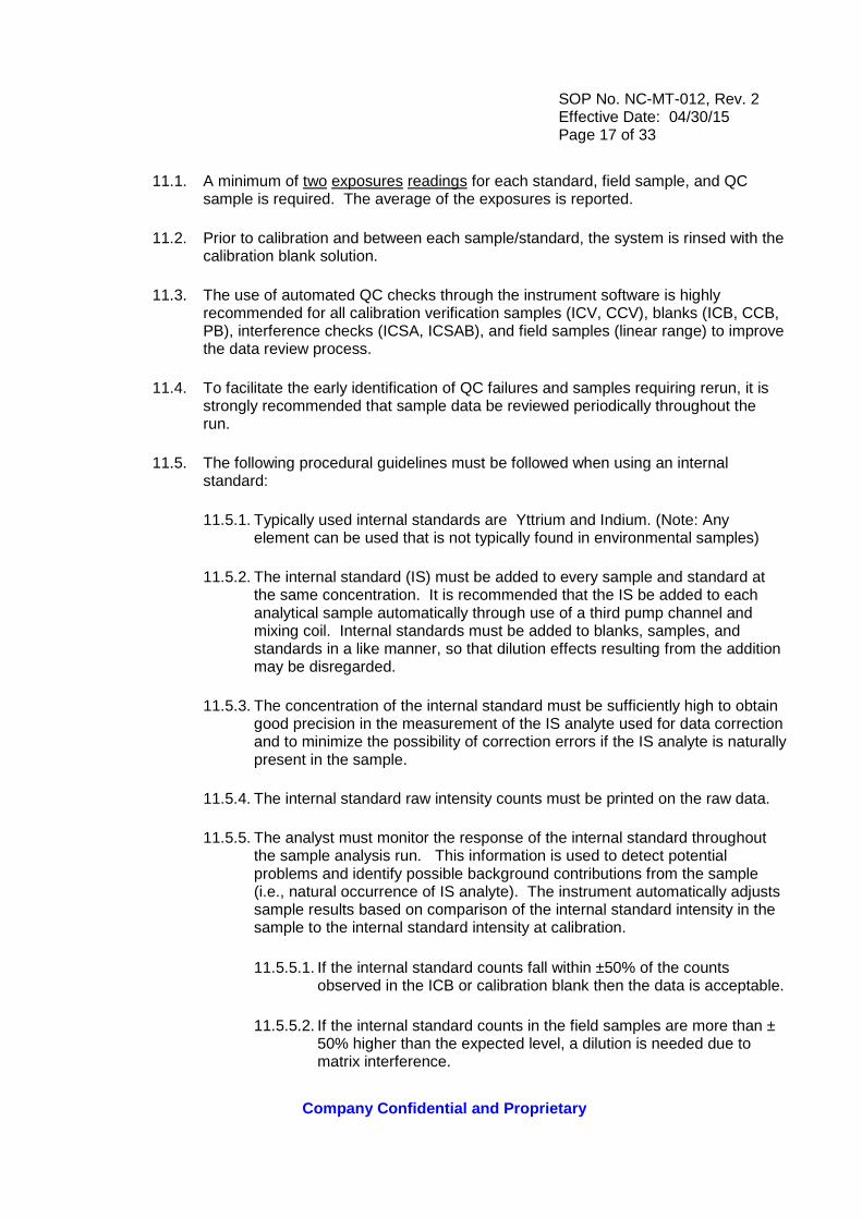
11.1. A minimum of two exposures readings for each standard, field sample, and QC sample is required. The average of the exposures is reported.
11.2. Prior to calibration and between each sample/standard, the system is rinsed with the calibration blank solution.
11.3. The use of automated QC checks through the instrument software is highly recommended for all calibration verification samples (ICV, CCV), blanks (ICB, CCB, PB), interference checks (ICSA, ICSAB), and field samples (linear range) to improve the data review process.
11.4. To facilitate the early identification of QC failures and samples requiring rerun, it is strongly recommended that sample data be reviewed periodically throughout the run.
11.5. The following procedural guidelines must be followed when using an internal standard:
11.5.1. Typically used internal standards are Yttrium and Indium. (Note: Any element can be used that is not typically found in environmental samples)
11.5.2. The internal standard (IS) must be added to every sample and standard at the same concentration. It is recommended that the IS be added to each analytical sample automatically through use of a third pump channel and mixing coil. Internal standards must be added to blanks, samples, and standards in a like manner, so that dilution effects resulting from the addition may be disregarded.
11.5.3. The concentration of the internal standard must be sufficiently high to obtain good precision in the measurement of the IS analyte used for data correction and to minimize the possibility of correction errors if the IS analyte is naturally present in the sample.
11.5.4. The internal standard raw intensity counts must be printed on the raw data.
11.5.5. The analyst must monitor the response of the internal standard throughout the sample analysis run. This information is used to detect potential problems and identify possible background contributions from the sample (i.e., natural occurrence of IS analyte). The instrument automatically adjusts sample results based on comparison of the internal standard intensity in the sample to the internal standard intensity at calibration.
11.5.5.1. If the internal standard counts fall within ±50% of the counts observed in the ICB or calibration blank then the data is acceptable.
11.5.5.2. If the internal standard counts in the field samples are more than ± 50% higher than the expected level, a dilution is needed due to matrix interference.

SOP No. NC-MT-012, Rev. 2 Effective Date: 04/30/15 Page 18 of 33
Company Confidential and Proprietary
11.6. The following analytical sequence must be used for Methods 6010B, 6010C, and 200.7:
Instrument Calibration ICV ICB CRI/LLICV (6010C) ICSA ICSAB CCV CCB 10 samples CCV CCB 10 samples CCV CCB Repeat sequence of up to 10 samples between CCV/CCB pairs as required to complete the run CRI (The CRI counts as a sample analysis.) /LLICV (6010C) CCV CCB
11.7. Refer to Quality Control Section 9.0 for Methods 6010B, 6010C, and 200.7 quality control criteria.
11.8. The following run sequence provides an illustration of a mid-run CCV or CCB failure and the appropriate corrective action run sequence as described in Section 10.5.
Original Run: Instrument Calibration ICV ICB CRI ICSA ICSAB CCV CCB 10 samples CCV CCB 10 samples CCV CCB 10 samples ** CCV * CCB * 10 samples ** CCV CCB 10 samples CCV
SOP No. NC-MT-012, Rev. 2 Effective Date: 04/30/15 Page 19 of 33
Company Confidential and Proprietary
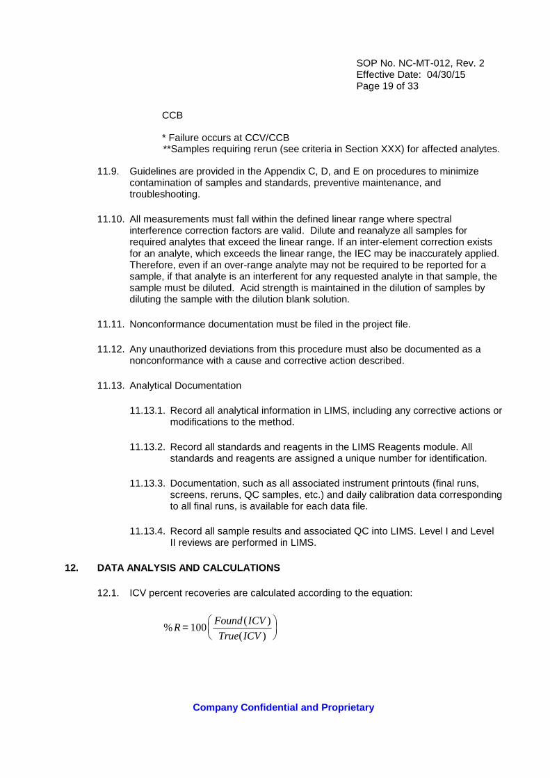
CCB * Failure occurs at CCV/CCB
**Samples requiring rerun (see criteria in Section XXX) for affected analytes.
11.9. Guidelines are provided in the Appendix C, D, and E on procedures to minimize contamination of samples and standards, preventive maintenance, and troubleshooting.
11.10. All measurements must fall within the defined linear range where spectral interference correction factors are valid. Dilute and reanalyze all samples for required analytes that exceed the linear range. If an inter-element correction exists for an analyte, which exceeds the linear range, the IEC may be inaccurately applied. Therefore, even if an over-range analyte may not be required to be reported for a sample, if that analyte is an interferent for any requested analyte in that sample, the sample must be diluted. Acid strength is maintained in the dilution of samples by diluting the sample with the dilution blank solution.
11.11. Nonconformance documentation must be filed in the project file.
11.12. Any unauthorized deviations from this procedure must also be documented as a nonconformance with a cause and corrective action described.
11.13. Analytical Documentation
11.13.1. Record all analytical information in LIMS, including any corrective actions or modifications to the method.
11.13.2. Record all standards and reagents in the LIMS Reagents module. All standards and reagents are assigned a unique number for identification.
11.13.3. Documentation, such as all associated instrument printouts (final runs, screens, reruns, QC samples, etc.) and daily calibration data corresponding to all final runs, is available for each data file.
11.13.4. Record all sample results and associated QC into LIMS. Level I and Level II reviews are performed in LIMS.
12. DATA ANALYSIS AND CALCULATIONS
12.1. ICV percent recoveries are calculated according to the equation:
%( )
( )R
Found ICV
True ICV=
100
SOP No. NC-MT-012, Rev. 2 Effective Date: 04/30/15 Page 20 of 33
Company Confidential and Proprietary
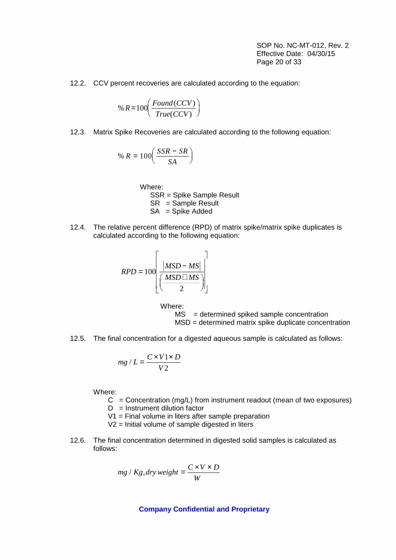
12.2. CCV percent recoveries are calculated according to the equation:
%( )
( )R
Found CCV
True CCV=
100
12.3. Matrix Spike Recoveries are calculated according to the following equation:
% RSSR SR
SA= −
100
Where:
SSR = Spike Sample Result SR = Sample Result SA = Spike Added
12.4. The relative percent difference (RPD) of matrix spike/matrix spike duplicates is calculated according to the following equation:
RPDMSD MS
MSD MS=
−+
100
2
Where: MS = determined spiked sample concentration MSD = determined matrix spike duplicate concentration
12.5. The final concentration for a digested aqueous sample is calculated as follows:
mg LC V D
V/ = × ×1
2
Where:
C = Concentration (mg/L) from instrument readout (mean of two exposures) D = Instrument dilution factor V1 = Final volume in liters after sample preparation V2 = Initial volume of sample digested in liters
12.6. The final concentration determined in digested solid samples is calculated as follows:
mg Kg dry weightC V D
W S/ , = × ×
×
SOP No. NC-MT-012, Rev. 2 Effective Date: 04/30/15 Page 21 of 33
Company Confidential and Proprietary
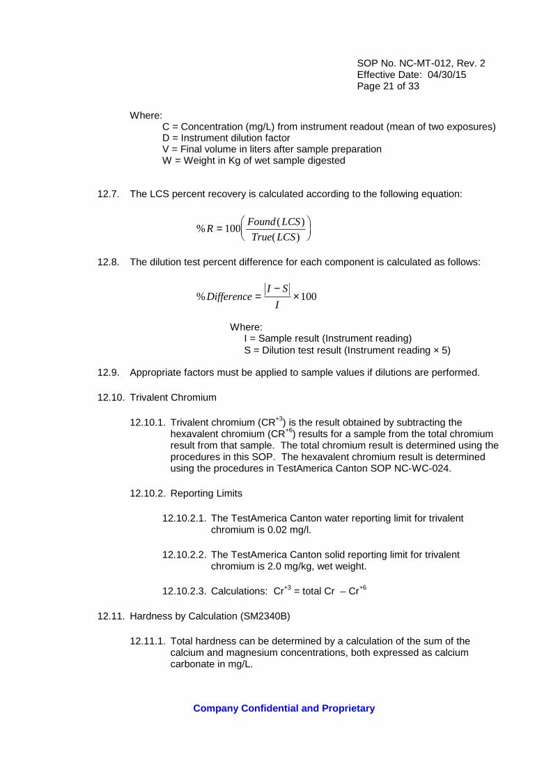
Where: C = Concentration (mg/L) from instrument readout (mean of two exposures) D = Instrument dilution factor V = Final volume in liters after sample preparation W = Weight in Kg of wet sample digested
12.7. The LCS percent recovery is calculated according to the following equation:
%( )
( )R
Found LCS
True LCS=
100
12.8. The dilution test percent difference for each component is calculated as follows:
%DifferenceI S
I=
−× 100
Where: I = Sample result (Instrument reading) S = Dilution test result (Instrument reading × 5)
12.9. Appropriate factors must be applied to sample values if dilutions are performed.
12.10. Trivalent Chromium
12.10.1. Trivalent chromium (CR+3) is the result obtained by subtracting the hexavalent chromium (CR+6) results for a sample from the total chromium result from that sample. The total chromium result is determined using the procedures in this SOP. The hexavalent chromium result is determined using the procedures in TestAmerica Canton SOP NC-WC-024.
12.10.2. Reporting Limits
12.10.2.1. The TestAmerica Canton water reporting limit for trivalent chromium is 0.02 mg/l.
12.10.2.2. The TestAmerica Canton solid reporting limit for trivalent chromium is 2.0 mg/kg, wet weight.
12.10.2.3. Calculations: Cr+3 = total Cr – Cr+6
12.11. Hardness by Calculation (SM2340B)
12.11.1. Total hardness can be determined by a calculation of the sum of the calcium and magnesium concentrations, both expressed as calcium carbonate in mg/L.
SOP No. NC-MT-012, Rev. 2 Effective Date: 04/30/15 Page 22 of 33
Company Confidential and Proprietary
12.11.2. Total Hardness mg equivalent CaCO3/L = [2.497 X (Ca concentration in mg/L)] + [4118 x (Mg concentration in mg/L)]
12.11.3. The reporting limit is 33 mg/L.
12.12. Additional equations and calculations are listed in the following SOPs: Calibration Curves (General), CA-Q-S-005, and Selection of Calibration Points, CA-T-P-Mel will insert this and copy to both 6010 and 6020.
13. METHOD PERFORMANCE
13.1. Each analyst must have initial demonstration of performance data on file for each analyte of interest as described in Section 9.0.
13.2. Refer to Table I in Appendix A for the list of analytes that may be analyzed using this SOP.
13.3. Training Qualification
13.3.1. The Group/Team Leader or the Supervisor has the responsibility to ensure this procedure is performed by an associate who has been properly trained in its use and has the required experience.
14. POLLUTION PREVENTION
14.1. It is TestAmerica’s policy to evaluate each method and look for opportunities to minimize waste generated (i.e., examine recycling options, ordering chemicals based on quantity needed, preparation of reagents based on anticipated usage and reagent stability). Employees must abide by the policies in Section 13 of the corporate environmental Health and Safety Manual (CW-E-M-001) for “Waste Management and Pollution Prevention”.
15. WASTE MANAGEMENT
15.1. All waste must be disposed of in accordance with Federal, State and Local laws and regulations. Where reasonably feasible, technological changes have been implemented to minimize the potential for pollution of the environment. Employees must abide by this method and the policies in Section 13 of the Corporate Environmental Health and Safety Manual (CW-E-M-001) for “Waste Management and Pollution Prevention.”
15.2. Waste Streams Produced by this Method
15.2.1. The following waste streams are produced when this method is carried out:
15.2.2. Acid waste consisting of sample and rinse solution: Any sample waste generated must be collected and disposed of in the acid waste drum located in the Metals Lab.
SOP No. NC-MT-012, Rev. 2 Effective Date: 04/30/15 Page 23 of 33
Company Confidential and Proprietary
15.2.3. Standards must be purchased and prepared in volumes consistent with laboratory use to minimize the volume of expired standards to be disposed.
16. REFERENCES
16.1. References
16.1.1. 40 CFR Part 136, Appendix B, 7-5-95, Determination of Method Detection Limits
16.1.2. Test Methods for Evaluating Solid Waste, Physical/Chemical Methods, SW-846, 3rd Edition, Final Update III, Revision 2, December 1996. Method 6010B
16.1.3. Test Methods for Evaluating Solid Waste, Physical/Chemical Methods, SW-846, Final Update IV, Method 6010C, Inductively Coupled Plasma-Atomic Emission Spectrometry, Revision 3, February 2007
16.1.4. Determination of Metals and Trace Elements in Water and Wastes by Inductively Coupled Plasma-Atomic Emission Spectrometry, Revision 4.4, May 1994. Method 200.7
16.1.5. Inductively Coupled Plasma – Atomic Emission Spectrometric Method for Trace Element Analysis of water and wastes Method 200.7, 40 CFR – Chapter I – Part 136 – Appendix C. Electronic version dated September 30, 2002
16.1.6. TestAmerica Canton Quality Assurance Manual (QAM), current version
16.1.7. TestAmerica Corporate Environmental Health and Safety Manual, CW-E-M-001, and TestAmerica Canton Facility Addendum and Contingency Plan, current version
16.1.8. Corporate Quality Management Plan (CQMP), current version
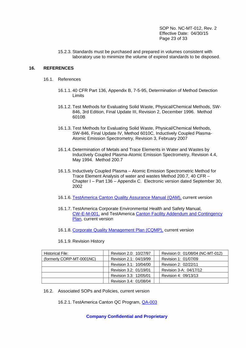
16.1.9. Revision History
Historical File: Revision 2.0: 10/27/97 Revision 0: 01/08/04 (NC-MT-012) (formerly CORP-MT-0001NC) Revision 2.1: 04/19/99 Revision 1: 01/07/09 Revision 3.1: 10/04/00 Revision 2: 02/22/11 Revision 3.2: 01/19/01 Revision 3-A: 04/17/12 Revision 3.3: 12/05/01 Revision 4: 09/13/13 Revision 3.4: 01/08/04
16.2. Associated SOPs and Policies, current version
16.2.1. TestAmerica Canton QC Program, QA-003

SOP No. NC-MT-012, Rev. 2 Effective Date: 04/30/15 Page 24 of 33
Company Confidential and Proprietary
16.2.2. Statistical Evaluation of Data and Development of Control Charts, NC-QA-018
16.2.3. Method Detection Limits and Instrument Detection Limits, NC-QA-021 and CA-Q-S-006
16.2.4. Hexavalent Chromium (Colorimetric), NC-WC-024
16.2.5. Acid Digestion of Soils, SW846 Method 3050B, NC-IP-010
16.2.6. Acid Digestion of Aqueous Samples by SW846 and MCAWW 200 Series Methods, NC-IP-011
16.2.7. Standards and Reagents, NC-QA-017
17. MISCELLANEOUS (TABLES, APPENDICES, ETC.)
17.1. Modifications/Interpretations from reference method
17.1.1. Modifications/interpretations from Methods 6010B and 200.7
17.1.1.1. TestAmerica Canton Laboratories use mixed calibration standard solutions purchased from approved vendors instead of using individual mixes prepared in-house as recommended by the subject methods.
17.1.1.2. Methods 200.7 and 6010B state that if the correction routine is operating properly, the determined apparent analyte(s) concentration from analysis of each interference solution must fall within a specific concentration range around the calibration blank. In determining IECs because of lack of definition clarification for “concentration range around the calibration blank,” TestAmerica Canton has adopted the procedure in EPA CLP ILMO4.0.
17.1.1.3. Whenever a new or unusual matrix is encountered, a series of tests must be performed prior to reporting concentration data for that analyte. The dilution test helps determine if a chemical or physical interference exists. Because TestAmerica Canton laboratories receive no prior information from clients regarding when to expect a new or unusual matrix, TestAmerica Canton may select to perform a dilution test on one sample in each prep batch. According to the method, the post digestion spike (PDS) determines any potential matrix interferences. At TestAmerica Canton, matrix interference is determined by evaluating data for the LCS and MS/MSD. TestAmerica Canton REQUIRES documented, clear guidance when a new or unusual matrix will be received for a project and a request to perform the dilution test or PDS on a specific client-identified sample.

SOP No. NC-MT-012, Rev. 2 Effective Date: 04/30/15 Page 25 of 33
Company Confidential and Proprietary
17.1.2. Modifications from Method 200.7
17.1.2.1. Method 200.7 defines the IDL for an element by determining the standard deviation of ten replicate measurements of the calibration blank signal at the wavelength specific to that element and multiplying it by three. TestAmerica Canton lab utilizes the IDL definition as defined in Section 9.1 of this SOP.
17.1.2.2. The calibration blank is prepared in an acid matrix of 5% HNO3/5% HCl instead of the specified 2% HNO3/10% HCl matrix [which method?] 200.7as the former matrix provides improved performance, relative to the wide variety of digestate acid matrices which result from the various EPA preparation protocols applied to samples. The laboratory runs these methods concurrently; therefore, the solution used is used for all analyses.
17.1.2.3. Method 200.7 Section 9.3.4 specifies that “Analysis of the ICV solution immediately following calibration must verify that the instrument is within ± 5% of calibration with a relative standard deviation <3% from four or more replicate integrations. TestAmerica Canton uses a minimum of two exposures for this determination.
17.1.2.4. The 40 CFR version of Method 200.7 requires the instrument check standard to agree within ± 5% of expected values and less than, or equal to, 3% RSD for replicate measurements. Also, the 40 CFR requires the interference check sample (ICSA) to be analyzed at the beginning, end, and at periodic intervals throughout the analytical sequence. At TestAmerica Canton, which must agree within ± 10% of expected values and 5% RSD for replicate measurements and the ICSA standards are analyzed only at the beginning of the analytical sequence . TestAmerica’s procedures are in line with the Rev. 4.4, May 1994 version of Method 200.7 Let’s check the ref method and see what it does say.
17.1.2.5. Section 7.12 of Method 200.7 indicates that the quality control sample ICV must be prepared at a concentration near 1 ppm. The ICV specified in this SOP accommodates the 1 ppm criteria for the majority of analytes. For the remaining analytes, this SOP specifies ICV concentrations which are appropriate to the range of calibration. The intent of the ICV, verification of the primary calibration standard accuracy, is independent of the ICV concentration used.
17.1.2.6. The ICS criteria applied by this SOP differ from those stated in the method. Method 200.7 Section 10.4 states that results must fall within the established control limits of 3 times the standard deviation of the calibration blank for that analyte.. The laboratory uses the following criteria: +/- RL or +/- 2xRL if RL is 10ug/L or less.

SOP No. NC-MT-012, Rev. 2 Effective Date: 04/30/15 Page 26 of 33
Company Confidential and Proprietary
17.1.2.7. Method 200.7 Section 9.3.4 states that concentrations detected in the CCB must be less than the IDL, but more than the lower 3-sigma control limit of the calibration blank. The intent of this requirement is to ensure that the calibration is not drifting at the low end TestAmerica Canton has adopted an absolute control limit of ± RL from zero for calibration blank criteria. SOP Section 10.5 provides the detailed corrective action criteria that must be followed.
17.1.3. Modifications from Method 6010B
17.1.3.1. Chapter 1 of SW-846 states that the method blank must not contain any analyte of interest at or above the MDL. This SOP states that the method blank must not contain any analyte of interest at or above the reporting limit. Common lab contaminants may be allowed up to two times the reporting limit in the blank following consultation with the client. This is not acceptable for Ohio VAP projects. For Ohio VAP projects, the MB must be clean down to the RL, unless the sample is non-detect below RL.
17.1.3.2. Method 6010B Section 8.6.1.3 states that the results of the calibration blank must be within three times the IDL. If not, repeat the analysis two or more times and average the results. If the average is not within three standard deviations of the background mean. TestAmerica Canton has adopted an absolute control limit of ± RL from zero for calibration blank criteria. See SOP Section 10.5 for a detailed description of the required corrective action procedures.

SOP No. NC-MT-012, Rev. 2 Effective Date: 04/30/15 Page 27 of 33
Company Confidential and Proprietary
APPENDIX A - TABLES
TABLE I: Methods 200.7, 6010B, and 6010C Target An alyte List
Element Symbol CAS #
Aluminum Al 7429-90-5 Antimony Sb 7440-36-0 Arsenic As 7440-38-2 Barium Ba 7440-39-3
Beryllium Be 7440-41-7 Boron B 7440-42-8
Cadmium Cd 7440-43-9 Calcium Ca 7440-70-2
Chromium Cr 7440-47-3 Cobalt Co 7440-48-4 Copper Cu 7440-50-8
Iron Fe 7439-89-6 Lead Pb 7439-92-1
Lithium Li 7439-93-2 Magnesium Mg 7439-95-4 Manganese Mn 7439-96-5 Molybdenum Mo 7439-98-7
Nickel Ni 7440-02-0 Potassium K 7440-09-7 Selenium Se 7782-49-2
Silicon Si 7440-21-3 Silver Ag 7440-22-4
Sodium Na 7440-23-5 Strontium Sr 7440-24-6 Thallium Tl 7440-28-0
Vanadium V 7440-62-2 Zinc Zn 7440-66-6 Tin Sn 7440-31-5
Titanium Ti 7440-32-6

SOP No. NC-MT-012, Rev. 2 Effective Date: 04/30/15 Page 28 of 33
Company Confidential and Proprietary
TABLE II: Matrix Spike and Aqueous Laboratory Cont rol Sample Levels
Element Concentration (ug/L) Aluminum 2000 Antimony 500 Arsenic 2000 Barium 2000
Beryllium 50 Cadmium 50 Calcium 50000
Chromium 200 Cobalt 500 Copper 250
Iron 1000 Lead 500
Lithium 1000 Magnesium 50000 Manganese 500 Molybdenum 1000
Nickel 500 Potassium 50000 Selenium 2000
Silicon 1000 Silver 50
Sodium 50000 Strontium 1000 Thallium 2000
Vanadium 500 Zinc 500
Boron 1000 Tin 2000
Titanium 1000
SOP No. NC-MT-012, Rev. 2 Effective Date: 04/30/15 Page 29 of 33
Company Confidential and Proprietary
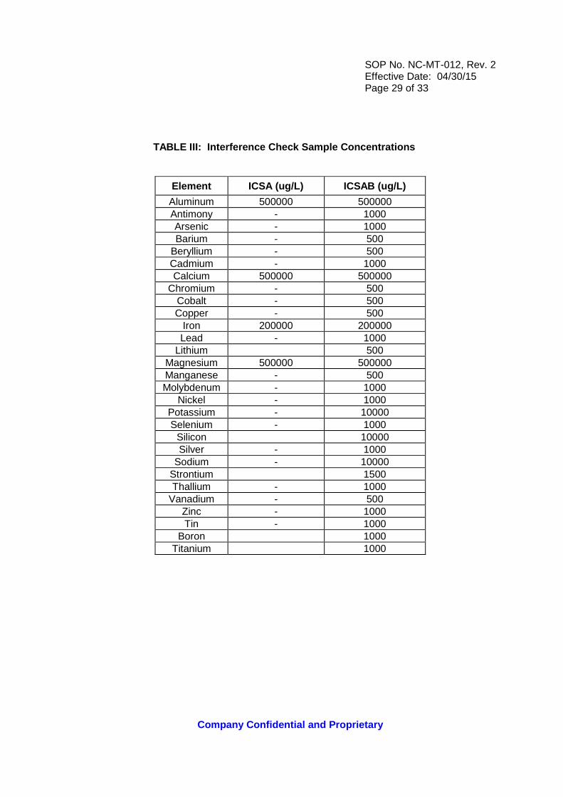
TABLE III: Interference Check Sample Concentration s
Element ICSA (ug/L) ICSAB (ug/L)
Aluminum 500000 500000 Antimony - 1000 Arsenic - 1000 Barium - 500
Beryllium - 500 Cadmium - 1000 Calcium 500000 500000
Chromium - 500 Cobalt - 500 Copper - 500
Iron 200000 200000 Lead - 1000
Lithium 500 Magnesium 500000 500000 Manganese - 500 Molybdenum - 1000
Nickel - 1000 Potassium - 10000 Selenium - 1000
Silicon 10000 Silver - 1000
Sodium - 10000 Strontium 1500 Thallium - 1000
Vanadium - 500 Zinc - 1000 Tin - 1000
Boron 1000 Titanium 1000
SOP No. NC-MT-012, Rev. 2 Effective Date: 04/30/15 Page 30 of 33
Company Confidential and Proprietary
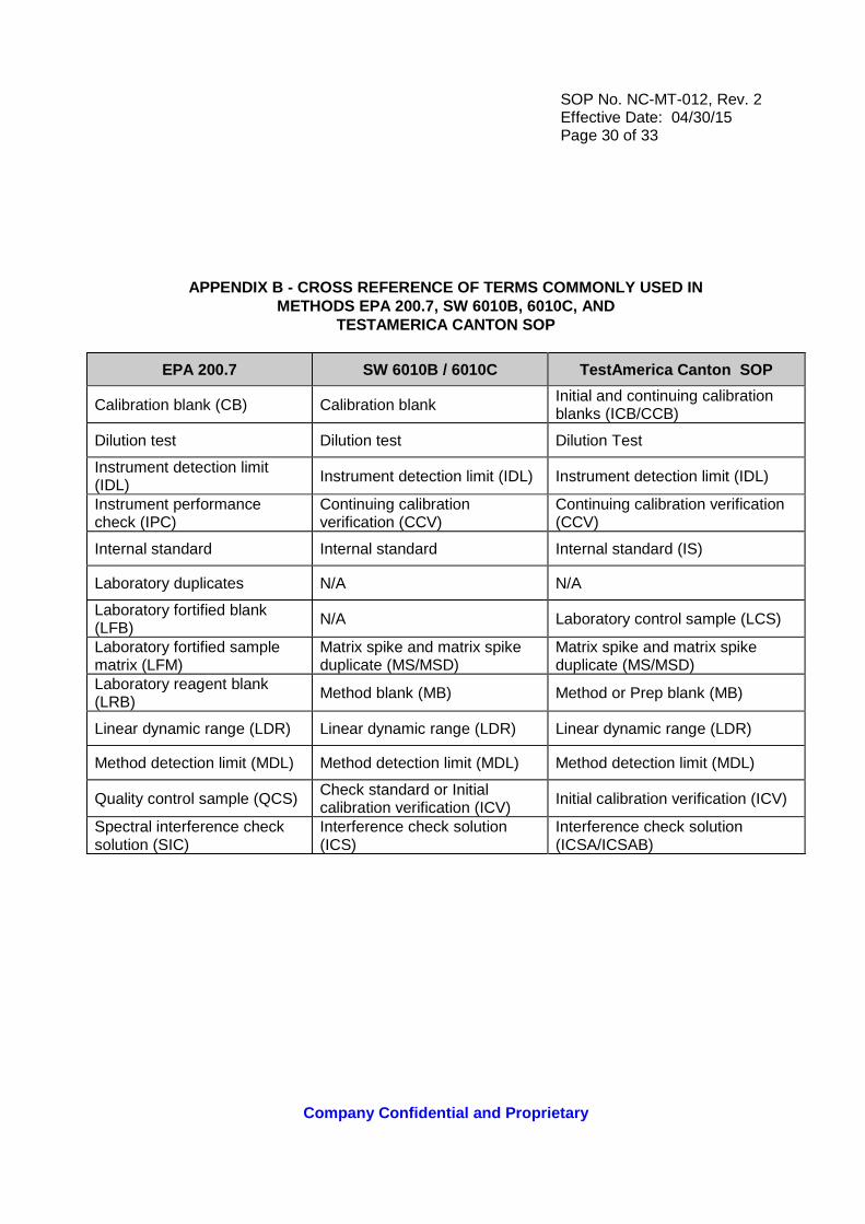
APPENDIX B - CROSS REFERENCE OF TERMS COMMONLY USED IN METHODS EPA 200.7, SW 6010B, 6010C, AND
TESTAMERICA CANTON SOP
EPA 200.7 SW 6010B / 6010C TestAmerica Canton SOP
Calibration blank (CB) Calibration blank Initial and continuing calibration blanks (ICB/CCB)
Dilution test Dilution test Dilution Test
Instrument detection limit (IDL) Instrument detection limit (IDL) Instrument detection limit (IDL)
Instrument performance check (IPC)
Continuing calibration verification (CCV)
Continuing calibration verification (CCV)
Internal standard Internal standard Internal standard (IS)
Laboratory duplicates N/A N/A
Laboratory fortified blank (LFB)
N/A Laboratory control sample (LCS)
Laboratory fortified sample matrix (LFM)
Matrix spike and matrix spike duplicate (MS/MSD)
Matrix spike and matrix spike duplicate (MS/MSD)
Laboratory reagent blank (LRB)
Method blank (MB) Method or Prep blank (MB)
Linear dynamic range (LDR) Linear dynamic range (LDR) Linear dynamic range (LDR)
Method detection limit (MDL) Method detection limit (MDL) Method detection limit (MDL)
Quality control sample (QCS) Check standard or Initial calibration verification (ICV) Initial calibration verification (ICV)
Spectral interference check solution (SIC)
Interference check solution (ICS)
Interference check solution (ICSA/ICSAB)

SOP No. NC-MT-012, Rev. 2 Effective Date: 02/22/11 Page 31 of 33
Company Confidential and Proprietary
APPENDIX C - TROUBLESHOOTING GUIDE
Problem Possible Cause/ Solution
High Blanks Increase rinse time Clean or replace tip Clean or replace torch Clean or replace sample tubing Clean or replace nebulizer Clean or replace mixing chamber
Instrument Drift Replace torch (Crack) Clean or replace nebulizer (blockage) Replace pump tubing Room humidity too high Clean torch tip (salt buildup) Check for argon leaks Re-profile
Erratic Readings, Flickering Torch or High RSD
Check for argon leaks Adjust sample carrier gas Replace tubing (clogged) Check drainage (back pressure changing) Increase uptake time (too short) Increase flush time (too short) Clean nebulizer, torch or spray chamber Increase sample volume introduced Check that autosampler tubes are full Sample or dilution of sample not mixed Increase integration time (too short) Realign torch Reduce amount of tubing connectors
Standards reading twice normal absorbance or concentration
Incorrect standard used Incorrect dilution performed

SOP No. NC-MT-012, Rev. 2 Effective Date: 02/22/11 Page 32 of 33
Company Confidential and Proprietary
APPENDIX D - CONTAMINATION CONTROL GUIDELINES
The following procedures are strongly recommended t o prevent contamination :
All glassware must be washed with detergent and tap water and rinsed with 1:1 nitric acid followed by deionized water.
Proper laboratory housekeeping is essential in the reduction of contamination in the Metals Lab. All work areas must be kept scrupulously clean.
Powdered Gloves must not be used in the Metals Lab since the powder contains silica and zinc as well as other metallic analytes. Glassware must be periodically checked for cracks and etches and discarded if found. Etched glassware can cause cross contamination of any metallic analytes.
The following are helpful hints in the identificati on of the source of contaminants :
Yellow pipette tips and volumetric caps can sometimes contain cadmium.
Some sample cups have been found to contain lead.
New glassware especially beakers can be a source of silica and boron.
Reagents or standards can contain contaminants or be contaminated with the improper use of a pipette.
Improper cleaning of glassware can cause contamination.
SOP No. NC-MT-012, Rev. 2 Effective Date: 02/22/11 Page 33 of 33
Company Confidential and Proprietary
APPENDIX E - PREVENTATIVE MAINTENANCE
A maintenance log is used to record when maintenance is performed on instruments. When an instrument problem occurs, indicate the date, time and instrument number. Then identify the problem and corrective action in the Maintenance Log.
The following procedures are required to ensure tha t that the instrument is fully operational :
Change sample pump tubing and pump windings
As Needed: Check rinse solution and fill if needed Check waste containers and empty if needed Check sample capillary tubing is clean and in good condition Check droplet size to verify nebulizer is not clogged. Check sample flow for cross flow nebulizer Check pressure for vacuum systems Clean plasma torch assembly to remove accumulated deposits
Clean nebulizer and drain chamber; keep free-flowing to maintain optimum performance Replace peristaltic pump tubing, sample capillary tubing and autosampler sipper probe Apply silicon spray on autosampler tracks Check water level in cool flow
Change oil for vacuum systems Replace coolant water filter (may require more or less frequently depending on quality of cooling water).