testbed for examiner on the continuous variable...
TRANSCRIPT

108
TESTBED FOR EXAMINER ON THE CONTINUOUS VARIABLE
TRANSMISSION
ИСПЫТАТЕЛЬНЫЙ СТЕНД ДЛЯ БЕССТУПЕНЧАТОЙ
ПЕРЕДАЧИ
СТЕНД ЗА ИЗПИТВАНЕ НА БЕЗСТЕПЕННА ВАРИАТОРНА
ТРАНСМИСИЯ
Doc. dr. Gigov B.1 , Conf. dr. eng. Motishev V.2 , dr. eng. Dimitrov Е.3
Faculty of Transport, – TU-Sofia, Bulgaria
E-mail: [email protected] 1; [email protected] 2 ; [email protected] 3;
Abstract: In the present report are described and analyses modules buildings test bed for examined on the Continuously Variable
Transmission (CVT). Described is and methods at examination to CVT in laboratory conditions.
KEYWORDS: SENSORS, STEPLESS TRANSMISSION, TESTBED, SHIFTING, CHARACTERISTICS
1. Introduction
In modern cars are used mostly traditional manual and
automatic speed gearboxes. However, they have some serious
drawbacks that are as follows:
- at manual gear boxes appear dynamic loads during gear
changes, that reduce the reliability of the various nodes of
the car transmission;
- have strict ratios of the individual gears that do not always
meet the operational mode of the engine;
- poor fuel economy of car;
- high toxicity of exhaust gases.
Order to avoid these shortcomings, the most important is to
ensure optimal modes of engine operation. At optimal mode of
engine load is decreases the toxicity of exhaust emissions and
improved fuel economy of cars. This mode is achieved by
continuously variable mechanical transmissions, which have the
property continuously and smoothly to change gear ratio
depending on engine load and road conditions. One of the most
used in automotive engineering mechanical continuously variable
transmission is a V-belt variator. With its built-in car are
achieved the following benefits:
- reduced toxicity of exhaust gases;
- improved fuel economy of cars;
- high reliability and capable of transmitting relatively high
torques;
- improved traction-speed properties of the car.
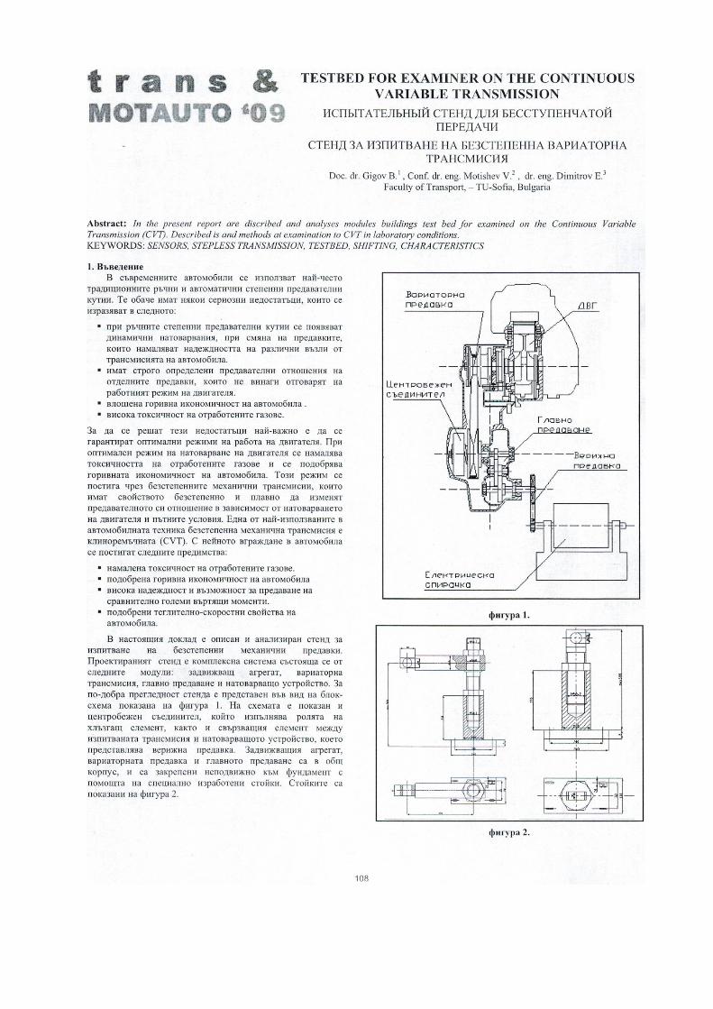
This report is described and analyzed test bench for stepless
mechanical gears. Designed stand is a complex system consisting
of the following modules: drive unit, CVT transmission, final
drive and loading unit. For better clarity, the stand is presented in
the form of a block diagram shown in Figure1. The diagram
shows and centrifugal clutch, which acts as a slipping element
and the connecting element between test transmission and
loading unit - represents a chain drive and electric brake. Drive
unit, CVT transmission and the main transmission in a common
housing and are fastened to the foundation with the help of
specially made stands. The stands are shown in Figure 2.
Figure 1.
Figure 2.
V-belt variator ICE
Centrifugal
clutch
Final drive
Chain drive
Electric brake
109
2. Description of individual modules of the stand
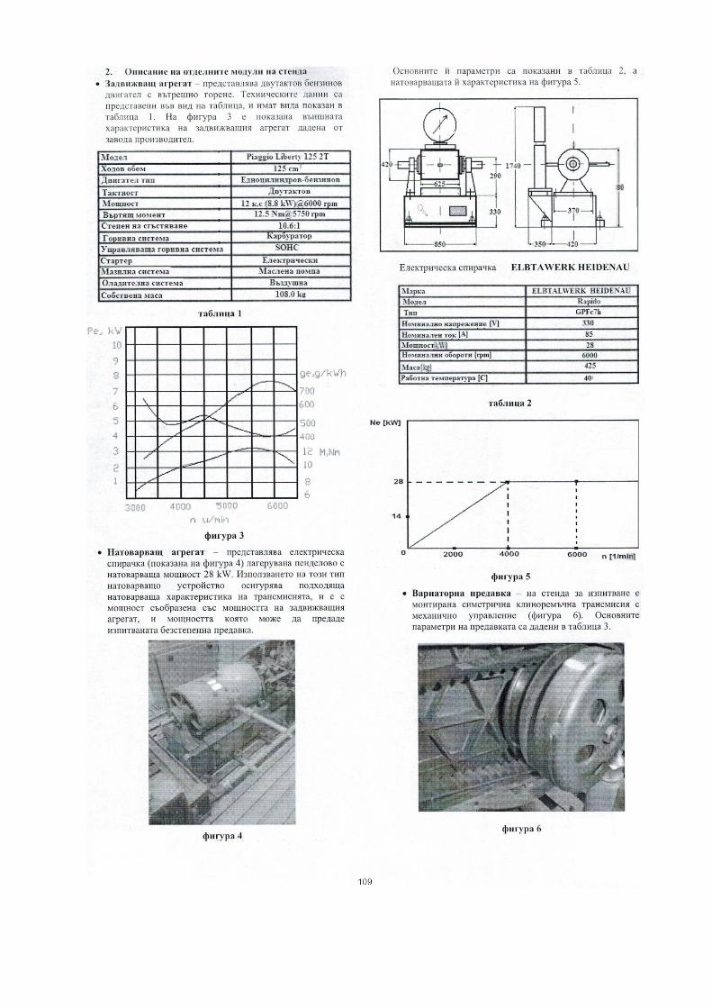
- Drive unit – it represents a two-stroke gasoline
internal combustion engine. The technical data are
presented in Table 1. Figure 3 shows the external
characteristics of the engine, given from the
manufacturer.
Table 1
Figure 3
- Loading unit – represents a pendel electric machine with
power 28 kW (shown in Figure 4). To the housing of the
electric generator is attached a lever for measuring the
reaction torque. For this purpose it is not stationary, but
stored of special hinge to the foundation. The use of this
type of loading unit ensures proper loading characteristics of
the transmission and has an output consistent with the power
of the drive unit and power, which can transmit
continuously variable test transmission.
Figure 4
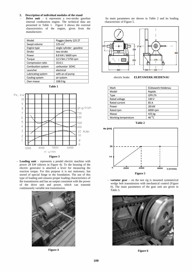
Its main parameters are shown in Table 2 and its loading
characteristic of Figure 5.
electric brake ELBTAWERK HEIDENAU
Table 2
Figure 5
- variator gear – on the test rig is mounted symmetrical
wedge belt transmission with mechanical control (Figure
6). The main parameters of the gear unit are given in
Table 3.
Figure 6
Model Piaggio Liberty 125 2T
Swept volume 125 cm3
Engine type single cylinder - gasoline
Stroke two stroke
Power 8.8 kW / 6600 rpm
Torque 12.5 Nm / 5750 rpm
Compression ratio 10.6:1
Combustion system carburetor SOHC
Launcher electrical
Lubricating system with an oil pump
Cooling system air system
Own masse 108.0 kg
Mark ELbtawerk Heidenau
Model Rapido
Type GPFc7h
Rated voltage 330 V
Rated current 85 A
Power 28 kW
Rated rpm 6000 rpm
Masse 425 kg
Working temperature 40 OC
110
Table 3
Laboratory module for testing variator transmissions is
equipped with sensors for speed, displacement and temperature.
The location of the sensors and recording devices are shown in
Figure 7.
Figure 7
1 – Drive unit (ICE);
2 – Variator transmission;
3 – Main drive;
4 – Sensor to engine speed;
5 – Sensor for displacement of the conical washer;
6 – Temperature sensor of ICE
7 – Sensor to rotational speed the output gear;
8 – Electric brake.
The sensor for engine speed is inductive type and receives a signal
from the ignition system of the engine. The ignition system is of a
type dynamo-magnet. The output signal of the sensor is in the form
of alternating voltage with 10V amplitude and frequency,
proportional to the engine speed. After entering in the metering
system voltage is converted to engine speed, rev / min.
A displacement sensor (shown in Figure 8) is of the inductive type.
Stand is equipped with a sensor type RF 232 with a measuring range
of movement 0-25 mm.
Figure 8
Geometric and technical data of the sensor are shown in Figure 9 and
Table 5.
Figure 9
Table 5
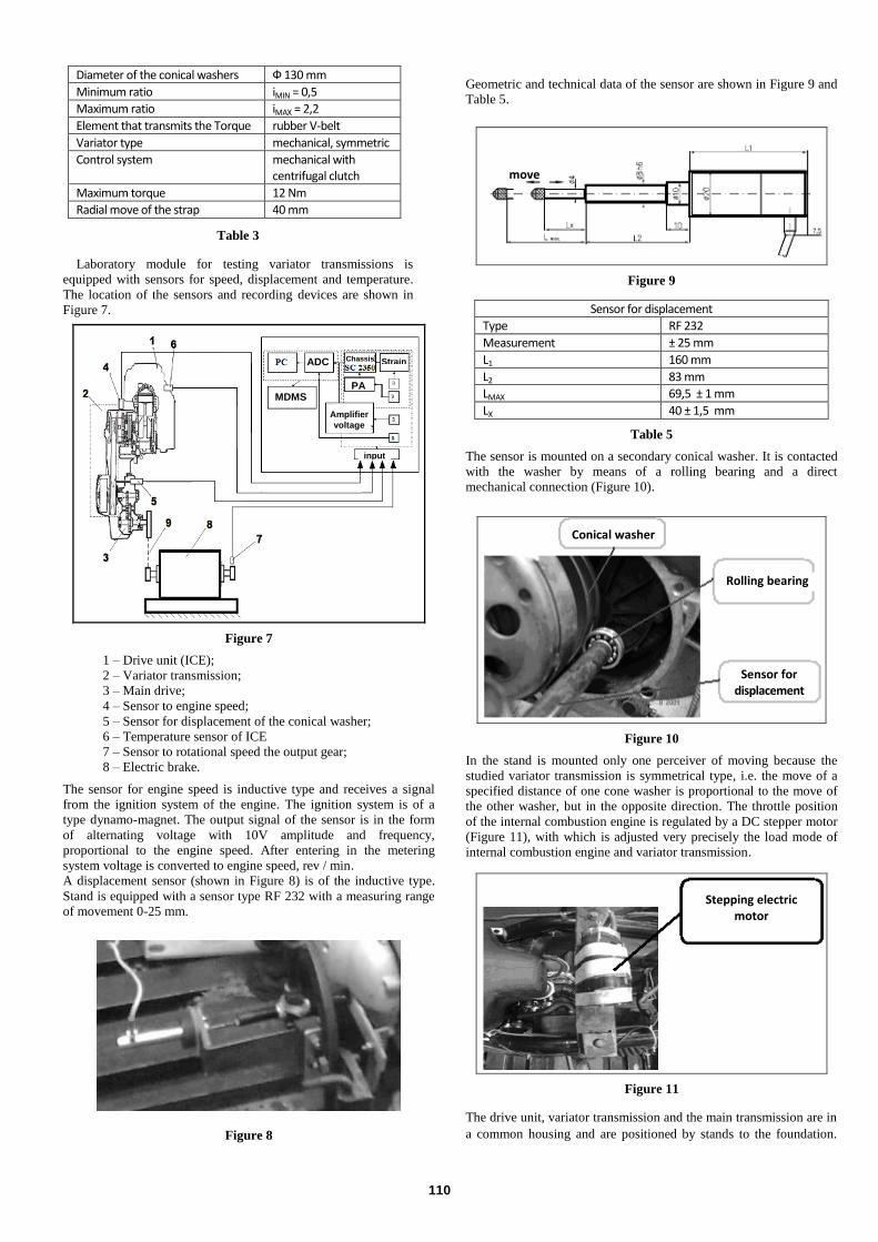
The sensor is mounted on a secondary conical washer. It is contacted
with the washer by means of a rolling bearing and a direct
mechanical connection (Figure 10).
Figure 10
In the stand is mounted only one perceiver of moving because the
studied variator transmission is symmetrical type, i.e. the move of a
specified distance of one cone washer is proportional to the move of
the other washer, but in the opposite direction. The throttle position
of the internal combustion engine is regulated by a DC stepper motor
(Figure 11), with which is adjusted very precisely the load mode of
internal combustion engine and variator transmission.
Figure 11
The drive unit, variator transmission and the main transmission are in
a common housing and are positioned by stands to the foundation.
Diameter of the conical washers Ф 130 mm
Minimum ratio iMIN = 0,5
Maximum ratio iMAX = 2,2
Element that transmits the Torque rubber V-belt
Variator type mechanical, symmetric
Control system mechanical with centrifugal clutch
Maximum torque 12 Nm
Radial move of the strap 40 mm
Sensor for displacement
Type RF 232
Measurement ± 25 mm
L1 160 mm
L2 83 mm
LMAX 69,5 ± 1 mm
LX 40 ± 1,5 mm
ADC
MDMS
Amplifier
voltage
input
Chassis Strain
PA
move
Conical washer
Rolling bearing
Sensor for displacement
Stepping electric motor

111
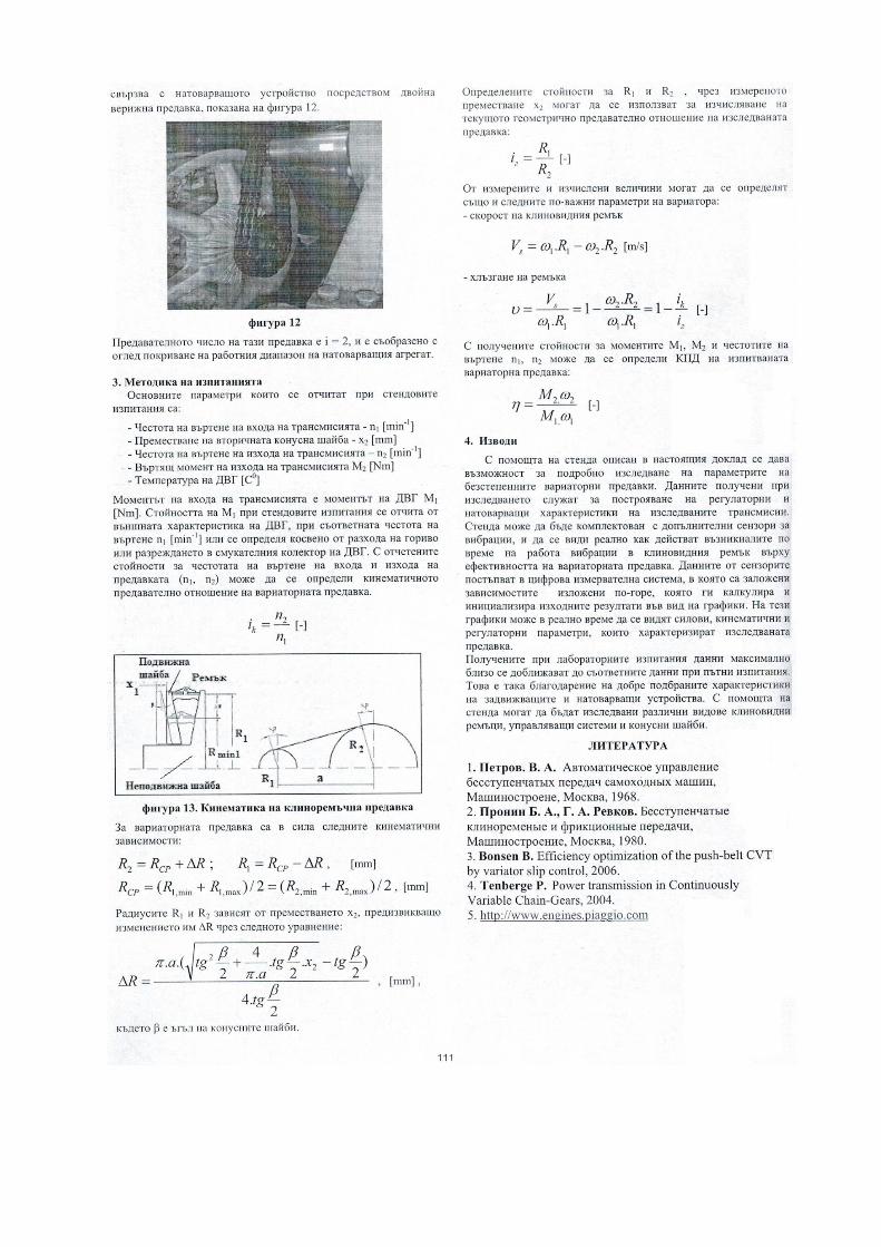
The output of variator transmission is associated with the loading
device via dual chain drive, shown in Figure 12.
Figure 12
The gear ratio of this gear is i = 2, and is in line to cover the working
range of the load unit.
3. Methodology of testing
The main parameters, that are considered at the bench tests are:
- Rotational speed of the input of the transmission - n1 [min-1]
- Moving the secondary cone washer - x2 [mm]
- Rotational speed of the output of the transmission – n2 [min-1]
- Torque on the output of the transmission – M2 [Nm]
- Temperature of ICE [C0]
The input torque of the transmission is the torque of ICE M1 [Nm].
The value of М1 in the bench tests is reported by external
characteristic of ICE at the respective speed n1 [min-1] or is
determined indirectly by fuel consumption or from rarefaction in
intake manifold of ICE. With the readings on the speed of the input
and output of the transmission. (n1, n2) can be determined kinematic
gear ratio of the variator gear.
1
2
n
nik [-]
Figure 13. Kinematics of V-belt transmission
For variator gear apply the following kinematic relationships:
RRRRRR СРСР 12 ; , [mm]
2/)(2/)( max,2min,2max,1min,1 RRRRRСР , [mm]
The radii R1 и R2 depend on the move х2, which causes their
amendment R by the following equation:
2.4
)2
.2
..
4
2.(. 2
2
tg
tgxtga
tga
R
, [mm] ,
where is angle of conical washers.
The determined values of R1 и R2 , by measuring displacement х2 can
be used to calculate the current geometric transmission ratio of the
test gear:
2
1
R
Riг [-]
From the measured and calculated values can be determined also
following important parameters of the variator:
- speed of the V-belt:
2211 .. RRVs [m/s]
- slip of the V-belt:
г
ks
i
i
R
R
R
V 1
.
.1
. 11
22
11
[-]
With the obtained values for the torques М1, М2 and for the rotational
frequencies n1, n2 can determine the efficiency of the tested variator:
1.1
2.2
M
M [-]
4. Conclusions
With the help of descriptions stand can thoroughly explore the
parameters of the stepless variator transmissions. The data, obtained
in the study serve to build regulatory and loading characteristics of
the studied transmissions. The tester can be equipped with additional
sensors for vibration, and see how it works real arisen during work
vibration the V-belt on the effectiveness of variator transmission.
Data from the sensors enters in the digital measuring system, in
which are set dependencies given out above. The output results are
obtained in the form of graphs. At those graphics can be seen in real
time power, kinematic and regulatory parameters, that characterize
the studied transmission.
The data, obtained at laboratory tests, the maximum come close to
relevant data at road tests. This is thanks to well-chosen features of
the drive and loading devices. With the help of the stand can be
explored various types of V-belts, control systems and conical
washers.
Bibliography
1. Петров. В. А. Автоматическое управлeние
бесступенчатых передач самоходных машин,
Машиностроене, Москва, 1968.
2. Пронин Б. А., Г. А. Ревков. Бесступенчатые
клиноременые и фрикционные передачи,
Машиностроение, Москва, 1980.
3. Bonsen B. Efficiency optimization of the push-belt CVT
by variator slip control, 2006.
4. Tenberge P. Power transmission in Continuously
Variable Chain-Gears, 2004.
5. http://www.engines.piaggio.com
Moving washer
V-belt
Stationary washer