testeur de câbles informatiques sefram 95 avant (1) connecteur rj45 (émetteur). (2) connecteur...
TRANSCRIPT
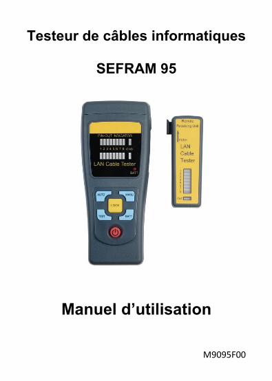
Testeur de câbles informatiques
SEFRAM 95
Manuel d’utilisation
M9095F00
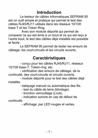
Introduction Le testeur de câbles informatiques SEFRAM 95 est un outil simple et pratique qui permet le test des câbles RJ45/RJ11 utilisés dans les réseaux 10/100 base-T et les Token Ring. Avec son module déporté qui permet de comparer ce qui est émis à un bout et ce qui est reçu à l’autre bout, le test des câbles déjà installés est possible et facile. Le SEFRAM 95 permet de tester les erreurs de câblage, les court-circuits et les circuits ouverts.
Caractéristiques - conçu pour les câbles RJ45/RJ11, réseaux 10/100 base-T, Token-ring, etc. - vérification des erreurs de câblage, de la continuité, des court-circuits et circuits ouverts. - module déporté pour le test des câbles déjà installés. - balayage manuel ou automatique des fils. - test du câble de terre (blindage) - fonction verrouillage (Lock). - indication sonore en cas de défaut de continuité. - affichage: par LED rouges et vertes.
- 1 -
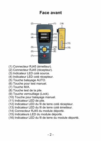
Face avant
(1) Connecteur RJ45 (émetteur). (2) Connecteur RJ45 (récepteur). (3) Indicateur LED coté source. (4) Indicateur LED coté récepteur. (5) Touche balayage AUTO. (6) Touche pour test manuel. (7) Touche M/A. (8) Touche test de la pile. (9) Touche verrouillage (Lock). (10) Touche pour balayage manuel. (11) Indicateur LED de pile. (12) Indicateur LED du fil de terre coté récepteur. (13) Indicateur LED du fil de terre coté émetteur. (14) Connecteur RJ45 du module déporté. (15) Indicateurs LED du module déporté. (16) Indicateur LED du fil de terre du module déporté.
- 2 -
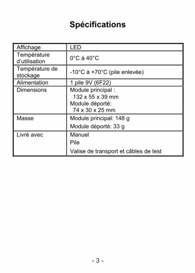
Spécifications
Affichage LED Température d’utilisation 0°C à 40°C
Température de stockage -10°C à +70°C (pile enlevée)
Alimentation 1 pile 9V (6F22) Dimensions Module principal :
132 x 55 x 39 mm Module déporté: 74 x 30 x 25 mm
Masse Module principal: 148 g Module déporté: 33 g Livré avec Manuel Pile Valise de transport et câbles de test
- 3 -
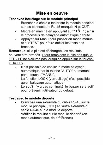
Mise en oeuvre Test avec bouclage sur le module principal
- Brancher le câble à tester sur le module principal sur les connecteurs RJ-45 marqué IN et OUT.
- Mettre en marche en appuyant sur " " ; ainsi le processus de balayage automatique débute.
- Appuyer sur Manu pour passer en mode manuel et sur TEST pour faire défiler les tests des broches.
Remarque: si la pile est déchargée, les résultats peuvent être erronés. Il faut remplacer la pile dès que la LED (11) ne s’allume pas lorsqu’on appuie sur la touche « BATT ».
- Il est possible de choisir le mode balayage automatique par la touche "AUTO" ou manuel par la touche "MANU".
- La fonction LOCK (verrouillage) n’est possible qu’en balayage automatique.
- Lorsqu’il n’y a pas continuité, le buzzer sera actif pour prévenir l’utilisateur du défaut.
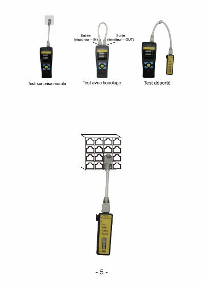
Test avec le module déporté
- Branchez une extrémité du câble RJ-45 sur le module principal (OUT) et l’autre extrémité du câble RJ-45 sur le module déporté.
- Vérifiez le résultat sur le module déporté (en mode automatique, de préférence)
- 4 -
- 5 -
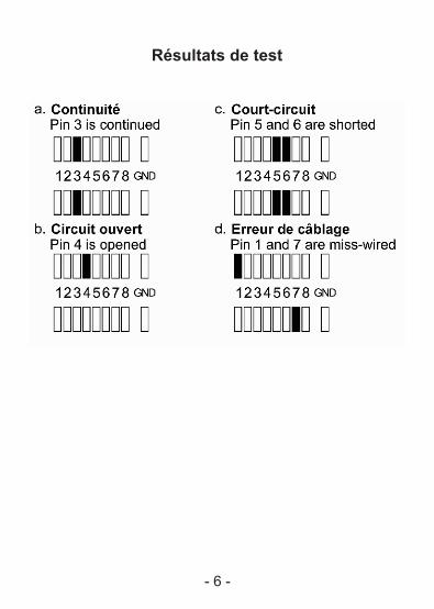
Résultats de test
- 6 -
Maintenance - Remplacement de la pile: en appuyant sur
"BATT", si la LED « BATT » ne s’allume pas, il faut remplacer la pile. Pour cela ouvrir le compartiment à l’arrière de l’appareil et remplacer la pile en respectant la polarité indiquée sur le connecteur.
- Nettoyage: à faire périodiquement avec une chiffon doux et humide. Ne pas utiliser de solvant.
Si vous n’utilisez pas votre testeur pendant plus de
de 2 mois, il est recommandé d’enlever la pile.
SEFRAM 32, rue Edouard Martel BP 55 F42009 – SAINT-ETIENNE Cedex 2 France Tel : 0825 56 50 50 (0.15€ttc/mn) Fax : 04 77 57 23 23 Web : www.sefram.fr Mail : [email protected] Support technique: [email protected]
- 7 -

LAN CABLE TESTER
INSTRUCTION MANUAL
Testeur de câbles informatiques
SEFRAM 95
Manuel d’utilisation
M9095F00
-1-
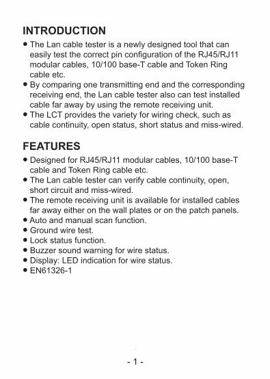
INTRODUCTIONl The Lan cable tester is a newly designed tool that can
easily test the correct pin configuration of the RJ45/RJ11 modular cables, 10/100 base-T cable and Token Ring cable etc.
l By comparing one transmitting end and the corresponding receiving end, the Lan cable tester also can test installed cable far away by using the remote receiving unit.
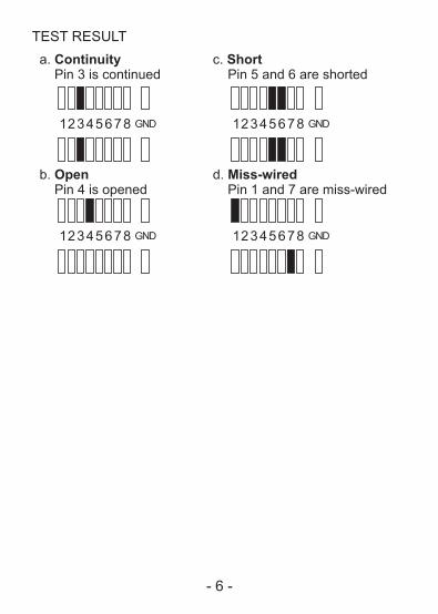
l The LCT provides the variety for wiring check, such as cable continuity, open status, short status and miss-wired.
FEATURESl Designed for RJ45/RJ11 modular cables, 10/100 base-T
cable and Token Ring cable etc.l The Lan cable tester can verify cable continuity, open,
short circuit and miss-wired.l The remote receiving unit is available for installed cables
far away either on the wall plates or on the patch panels.l Auto and manual scan function.l Ground wire test.l Lock status function.l Buzzer sound warning for wire status.l Display: LED indication for wire status.l EN61326-1
- 1 -
-2-
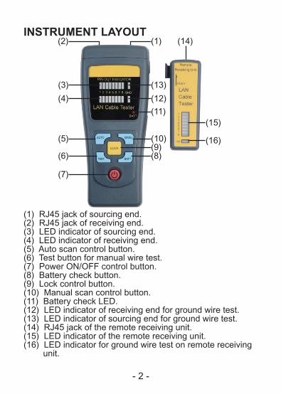
INSTRUMENT LAYOUT
(1) RJ45 jack of sourcing end.(2) RJ45 jack of receiving end.(3) LED indicator of sourcing end.(4) LED indicator of receiving end.(5) Auto scan control button.(6) Test button for manual wire test.(7) Power ON/OFF control button.(8) Battery check button.(9) Lock control button.(10) Manual scan control button.(11) Battery check LED.(12) LED indicator of receiving end for ground wire test.(13) LED indicator of sourcing end for ground wire test.(14) RJ45 jack of the remote receiving unit.(15) LED indicator of the remote receiving unit.(16) LED indicator for ground wire test on remote receiving unit.
(2)
(3)
(4)
(5)
(6)
(7)
(1)
(9)(8)
(11)
(10)
(15)
(16)
(12)
(13)
(14)
- 2 -
-3-
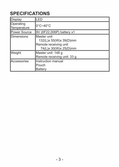
SPECIFICATIONSDisplay LEDOperatingTemperature
0°C~40°C
Power Source 9V (6F22,006P) battery x1Dimensions Master unit
132(L)x 55(W)x 39(D)mmRemote receiving unit 74(L)x 30(W)x 25(D)mm
Weight Master unit: 148 gRemote receiving unit: 33 g
Accessories Instruction manualPouchBattery
- 3 -
-4-
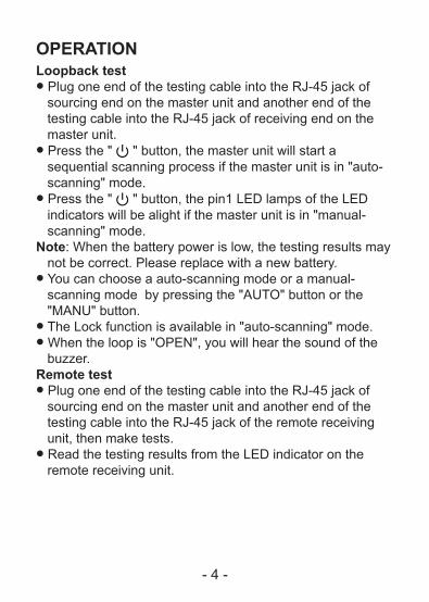
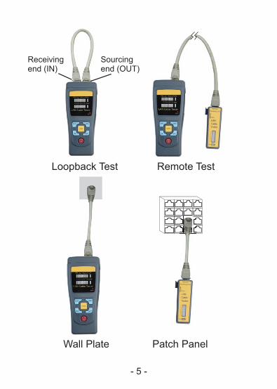
OPERATIONLoopback testl Plug one end of the testing cable into the RJ-45 jack of
sourcing end on the master unit and another end of the testing cable into the RJ-45 jack of receiving end on the master unit.
l Press the " " button, the master unit will start a sequential scanning process if the master unit is in "auto-scanning" mode.
l Press the " " button, the pin1 LED lamps of the LED indicators will be alight if the master unit is in "manual-scanning" mode.
Note: When the battery power is low, the testing results may not be correct. Please replace with a new battery.l You can choose a auto-scanning mode or a manual-
scanning mode by pressing the "AUTO" button or the "MANU" button.
l The Lock function is available in "auto-scanning" mode.l When the loop is "OPEN", you will hear the sound of the
buzzer.Remote testl Plug one end of the testing cable into the RJ-45 jack of
sourcing end on the master unit and another end of the testing cable into the RJ-45 jack of the remote receiving unit, then make tests.
l Read the testing results from the LED indicator on the remote receiving unit.
- 4 -
-5-
Loopback Test Remote Test
Patch PanelWall Plate
Receiving end (IN)
Sourcingend (OUT)
- 5 -
-6-
TEST RESULT
- 6 -
-7-
MAINTENANCEl Battery replacement: When press the "BATT" button, if the "BATT LED" doesn't
glow, replace with a new 9V battery.l Cleaning and storage: Periodically wipe the case deterged with a damp cloth; do
not use abrasives or solvents.
If the meter is not to be used for periods of longer than 60 days, remove the battery and store them separately.
- 7 -
SEFRAM 32, rue Edouard Martel BP 55 F42009 – SAINT-ETIENNE Cedex 2 France Tel : +33 4 77 59 01 01 Fax : +33 4 77 57 23 23 Web : www.sefram.fr Mail : [email protected] Support technique: [email protected]