testing and development of feed-forward system for atf2 a. kalinin accelerator science and...
TRANSCRIPT

Testing and Development of
Feed-Forward System for ATF2
A. Kalinin
Accelerator Science and Technology Centre, Daresbury Laboratory, UK
Fifth ATF2 Project Meeting KEK, December 19, 2007

The bunch-by-bunch Feed-Forward Correction (FF) done at ATF2 EXT is intended for transverse jitter originated in DR.
In DR, at start of the last turn, the bunch position and angle are measured with a pair of BPMs, and the correction is applied to the same bunch in EXT, using a pair of kickers. The propagation time (feed-forward time) is about 0.4μs.
correction residue << beam size
2007
1. FF Layout. Places of pickups and kickers in EXT.2. FF Layout. Places of pickups and kickers in DR.3. FF Matrix and FF Gain measurement.4. BPM prototype beam test result.
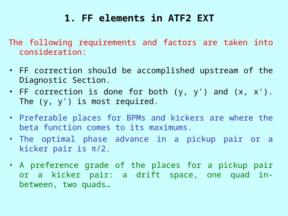
1. FF elements in ATF2 EXT
The following requirements and factors are taken into consideration:
• FF correction should be accomplished upstream of the Diagnostic Section.
• FF correction is done for both (y, y') and (x, x'). The (y, y') is most required.
• Preferable places for BPMs and kickers are where the beta function comes to its maximums.
• The optimal phase advance in a pickup pair or a kicker pair is π/2.
• A preference grade of the places for a pickup pair or a kicker pair: a drift space, one quad in-between, two quads…

(continued)
• A kicker in each pair has an adjacent pickup that is necessary for FF matrix measurements.
• For FF correction residue measurement, a FB downstream pickup pair can be used.
• A pickup is a standard EXT (x, y) 12cm strip line pickup. Some pickups in EXT are shared by FF and FB and some of them by the EXT Orbit system as well.
• The kickers are common for FF and FB. Combining the kick signals is done on the kicker amplifier input.
• A kicker is a single plane strip line kicker. The length is supposed to be about 30cm.

7

8

7
Ky1
P2y
P4y
Ky2
P1xKx1 P3x
Kx2

Some conclusions and observations
• The sqrt beta values at the pickups and kickers are typically somewhat lower than 2. This makes the requirement to the BPM resolution as tight as 1μm.
• The optimal position of a kicker or a pickup may fall in the place of other device. Combining is possible, as a steering magnet on a kicker/pickup, etc.
• A single plane strip line kicker can be similar to the KEK ILC prototype fitted to the EXT aperture. The length with flanges is taken as 35cm. The pickup length is taken as 15cm.
• It is supposed that we know how to split the pickup signals precisely.
• Attention should be taken to imbalance of the pair of pickup strip lines. Imbalance may deteriorate performance of the dif-sum BPM. In advance to installation, the pickups should be tested on a coaxial wire bench.

2. FF DR Pickups
12

• Pickup 1 is downstream of Q6 in LQ6C (93.05m), pickup 2 is downstream of Q17 in LZV43 (115.63m).
• Vertical phase advance in the pair is π/2, horizontal one is about π/4.
• These FF pickups are supposed to be special DR pickups which are identical to the present EXT 12cm strip line pickups.

3.

4. Feed-Forward BPM Resolution TestATF Weekly Meeting, 17 December 2007
• Objective: For a single-bunch strip-line BPM break through to 1um resolution (a 14bit BPM).
• Two types of single bunch BPMs were tested with beam: a FF dif-sum BPM and a BPM with multiplexing two pickup signals into a single channel.
A set of newly designed circuits common for both the types: Square Wave Cascaded Couplers, Low Noise Input Amplifiers, Synchronous Detectors (SD), a Beam-Based SD Clock, Low Noise ADC Driver.

A simplest resolution measurement methodwas used:
• One pickup strip line – cable – Coupler – Splitter – two inputs of Dif-Sum BPM.
• Another pickup strip line - cable – Coupler – Splitter – two inputs of Multiplex BPM.
With two or more BPMs available, a more advanced method can be used: the BPMs are connected in parallel to same pickup. STD of difference of the readings.
• With two BPM in parallel, they should be identical. With
three or more BPMs in parallel, the resolution of each BPM can be calculated individually.

The BPM signals at a 2GHz 14bit ADC (GFT)

Preliminary processing was done for the FF Dif-Sum BPM, and the resolution has been calculated.
• Picking up the values from the data arrays, a table can be filled, and then standard deviation of the ‘position’ can be calculated.
• Two arrays from the recorded data were analysed.• First 30 samples were used.• No fliers were removed. It was two-three big positive and two-
three big negative fluctuations. Not knowing the distribution, these fluctuations were retained.
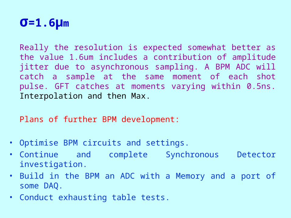
σ=1.6μm
Really the resolution is expected somewhat better as the value 1.6um includes a contribution of amplitude jitter due to asynchronous sampling. A BPM ADC will catch a sample at the same moment of each shot pulse. GFT catches at moments varying within 0.5ns. Interpolation and then Max.
Plans of further BPM development:
• Optimise BPM circuits and settings.• Continue and complete Synchronous Detector investigation.• Build in the BPM an ADC with a Memory and a port of some
DAQ.• Conduct exhausting table tests.