testing distributed pv as part of a larger electric system · remote phil and co-simulation test...
TRANSCRIPT

NREL is a national laboratory of the U.S. Department of Energy, Office of Energy Efficiency and Renewable Energy, operated by the Alliance for Sustainable Energy, LLC.
Testing Distributed PV as Part of a Larger Electric System
Presenter: Anderson Hoke, P.E. - NREL
Integrating PV in Distribution Grids: Solutions and Technologies Workshop October 23, 2015
2
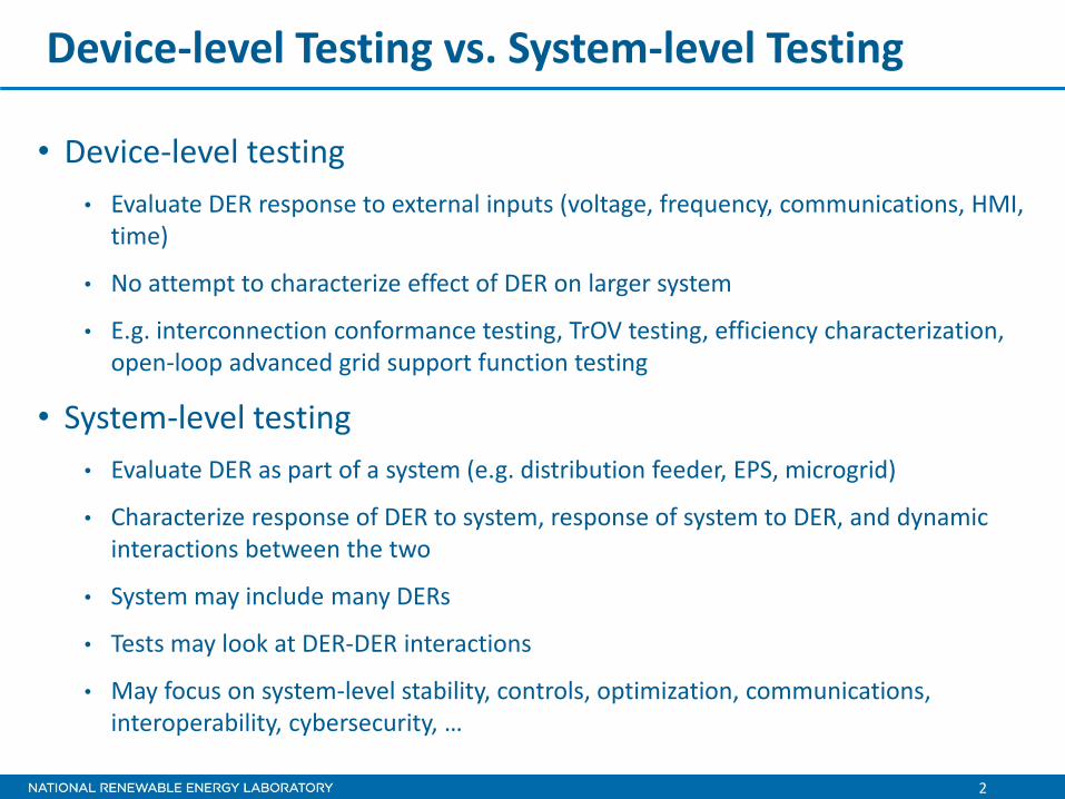
Device-level Testing vs. System-level Testing
• Device-level testing
• Evaluate DER response to external inputs (voltage, frequency, communications, HMI, time)
• No attempt to characterize effect of DER on larger system
• E.g. interconnection conformance testing, TrOV testing, efficiency characterization, open-loop advanced grid support function testing
• System-level testing
• Evaluate DER as part of a system (e.g. distribution feeder, EPS, microgrid)
• Characterize response of DER to system, response of system to DER, and dynamic interactions between the two
• System may include many DERs
• Tests may look at DER-DER interactions
• May focus on system-level stability, controls, optimization, communications, interoperability, cybersecurity, …
3
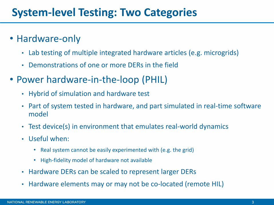
System-level Testing: Two Categories
• Hardware-only • Lab testing of multiple integrated hardware articles (e.g. microgrids)
• Demonstrations of one or more DERs in the field
• Power hardware-in-the-loop (PHIL) • Hybrid of simulation and hardware test
• Part of system tested in hardware, and part simulated in real-time software model
• Test device(s) in environment that emulates real-world dynamics
• Useful when:
• Real system cannot be easily experimented with (e.g. the grid)
• High-fidelity model of hardware not available
• Hardware DERs can be scaled to represent larger DERs
• Hardware elements may or may not be co-located (remote HIL)
Hardware System Level Testing Examples
5
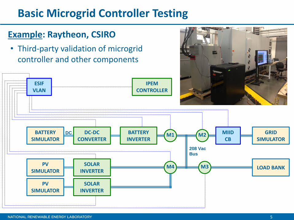
Basic Microgrid Controller Testing
Example: Raytheon, CSIRO
BATTERY INVERTER
M1 M2
M3 M4 SOLAR INVERTER
MIID CB
IPEM CONTROLLER
DC-DC CONVERTER
GRID SIMULATOR
LOAD BANK
BATTERY SIMULATOR
PV SIMULATOR
SOLAR INVERTER
PV SIMULATOR
ESIF VLAN
208 Vac
Bus
DC
• Third-party validation of microgrid controller and other components

PHIL System-level Testing Examples
7
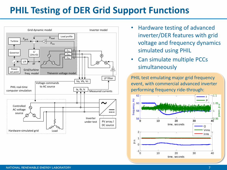
PHIL Testing of DER Grid Support Functions
• Hardware testing of advanced inverter/DER features with grid voltage and frequency dynamics simulated using PHIL
• Can simulate multiple PCCs simultaneously
PHIL real-time computer simulation
Voltage commands to AC source
ZTh
Grid dynamic model Inverter model
Va, Vb, Vc
Ia, Ib, Ic
LP filter
++Pgrid
Pinv
-Pload
Load profile
∆f1/R+-
Power set point
Governor
Turbine a
b
Measured currents
ZTh
ZTh
Thévenin voltage modelGrid/turbine freq. model
1/(2Hs+D)
Inverterunder test PV array /
DC source
Controlled AC voltage
source
~
LoadHardware-simulated grid
PHIL test emulating major grid frequency event, with commercial advanced inverter performing frequency ride-through:
0 10 20 30 4056
58
60
62
freq
uen
cy,
Hz
time, seconds
0 10 20 30 40-1
0
1
2
time, seconds
p.u
.
0 10 20 30 400.95
1
1.05
1.1x 10
10
pow
er,
p.u
.
f
P
Q
Vrms
Irms
8
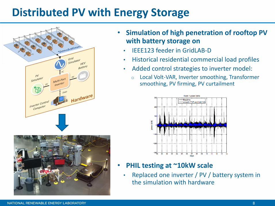
Distributed PV with Energy Storage
• Simulation of high penetration of rooftop PV with battery storage on • IEEE123 feeder in GridLAB-D
• Historical residential commercial load profiles
• Added control strategies to inverter model: o Local Volt-VAR, Inverter smoothing, Transformer
smoothing, PV firming, PV curtailment
• PHIL testing at ~10kW scale • Replaced one inverter / PV / battery system in
the simulation with hardware
9
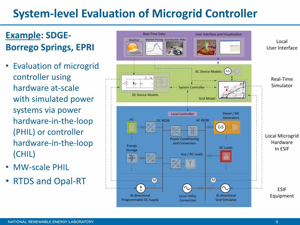
System-level Evaluation of Microgrid Controller
Example: SDGE- Borrego Springs, EPRI
• Evaluation of microgrid controller using hardware at-scale with simulated power systems via power hardware-in-the-loop (PHIL) or controller hardware-in-the-loop (CHIL)
• MW-scale PHIL
• RTDS and Opal-RT
PV
Energy Storage
Diesel / NG Generators
AC Loads
Aux / DC Loads
GS
Local Controller
Power Conditioningand Conversion
DC REDB AC REDB
Grid ModelDC Device Models
Bi-directionalProgrammable DC Supply
Bi-directionalGrid Simulator
M M
Local MicrogridHardware
In ESIF
ESIFEquipment
Distribution PMUWeather
Real-Time Data User Interface and Visualization
Real-TimeSimulator
LocalUser Interface
Ipv Id Rp
Rs
V
I
Market Pricing
Local UtilityConnection
GSAC Device Models
System Controller PCC

10
PHIL-based Development and Validation for ESI
PV Simulator
AC RLC Load BankInverterLocal PCC Model
Grid Simulator
M
Local Controller
Grid Model
DC
RED
B
M
AC REDB
Vpcc
Iinv
Vpcc
Vpcc
Iinv
Static
PV Array
Use of PHIL techniques to evaluate novel energy system devices and control systems connected to specific network configurations involves:
1. Validation of PHIL simulation configuration for a known condition (e.g., field data or hardware) to ensure reliability of technique with particular hardware
2. PHIL simulation with updated devices, models, or control systems to prove new developments before field implementation
11
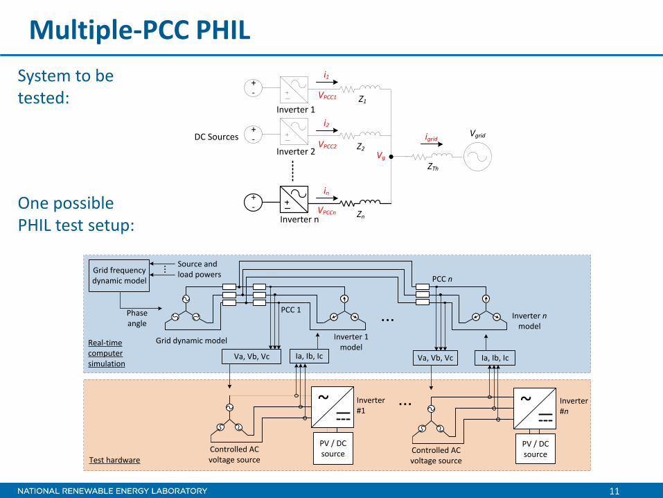
Multiple-PCC PHIL
System to be tested:
+-
+-
Z1
Inverter 1
Inverter 2
DC SourcesZ2
ZTh
Vgrid
i1
i2
VPCC1
igrid
+-
Inverter nZn
in
VPCC2
VPCCn
Vg
Inverter#1
Real-time computer simulation
Controlled AC voltage source
~
Grid dynamic model Inverter 1 model
Va, Vb, Vc Ia, Ib, Ic
Test hardware
PV / DC source
Inverter n model
Inverter#n
Controlled AC voltage source
~
Va, Vb, Vc Ia, Ib, Ic
PV / DC source
...
...
... Source and load powersGrid frequency
dynamic model
Phase angle
PCC n
PCC 1
One possible PHIL test setup:

12
Multi-inverter, Multi-PCC Volt-VAr Test
Reactive power
cycling between two
inverters with high
Q(V) slope
(a) (d)
(b) (e)
(c) (f)
(g)
(h)
(i)
Inverter#1
Real-time computer simulation
Controlled AC voltage source
~
Grid dynamic model Inverter 1 model
Va, Vb, Vc Ia, Ib, Ic
Test hardware
ZTh ZInv ZInv
PV / DC source
Inverter 2 model
Inverter#2
Controlled AC voltage source
~
Va, Vb, Vc Ia, Ib, Ic
PV / DC source
Vgrid
Test 14
1 2 3 4 5 6 7 8 90.8
1
1.2
1.4
time, seconds
voltage /
curr
ent,
p.u
.
1 2 3 4 5 6 7 8 9-2000
0
2000
4000
time, seconds
VA
Vrms1
Irms1
Vrms2
Irms2
Q1
P1
S1
Q2
P2
S2
Instability caused by
slower volt-VAr
response time • Simulated impedance in loop with actual inverters
– two different inverters from leading manufacturers
• Experimental validation with transient PHIL – no problems found in limited testing to date

13
Remote PHIL and Co-simulation Test Bed
Combines actual hardware testing using PHIL with co-simulation of larger electric power grid using off-the-shelf modeling tools. Very flexible architecture enables multi-site testing (e.g. NREL links to PNNL and CSIRO), and scenario flexibility
Very Flexible: • Arbitrary Grid: location, topology & equipment
• Demo: IEEE 8500 and 123 with no hardware changes
• Any scenario: normal ops, faults, contingencies • Demo: Cloud transients, home thermal physics
models • Actual hardware: no proprietary models required
• Demo: 2 advanced inverters at various points of common coupling
• Multi-site: hardware and/or simulation • Demo: PNNL (WA) link to NREL (CO) • CSIRO (Australia)
14
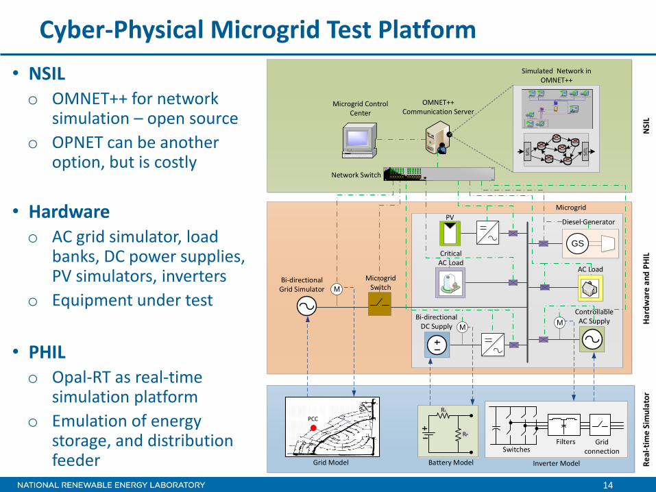
Cyber-Physical Microgrid Test Platform
• NSIL o OMNET++ for network
simulation – open source
o OPNET can be another option, but is costly
• Hardware o AC grid simulator, load
banks, DC power supplies, PV simulators, inverters
o Equipment under test
• PHIL o Opal-RT as real-time
simulation platform
o Emulation of energy storage, and distribution feeder
PVDiesel Generator
AC Load
GS
Bi-directionalDC Supply
Bi-directionalGrid Simulator
M
M
Critical AC Load
Controllable AC SupplyM
Microgrid Switch
Grid Model
PCC
Battery Model
SwitchesFilters Grid
connection
Inverter Model
Rs
RP
Microgrid
Microgrid Control Center
Network Switch
OMNET++ Communication Server
SITL
SITL
Re
al-t
ime
Sim
ula
tor
Ha
rdw
are
an
d P
HIL
NSI
L
Simulated Network in OMNET++