testing machines and systems for metals · testing machines and systems for metals ... these...
TRANSCRIPT
Testing Machines andSystems for Metals
Intelligent Testing
FP
253 2
.1104.2
02
Testing Systems
2
The Zwick Roell Group –More than a centuryof experience inmaterials testing
The mechanical-technologicaltesting is the oldest discipline ofmaterials testing. As early as in the15th and 16th century, Leonardoda Vinci and Galileo Galilei werealready considering the flexuralstressing and the elastic behaviourof materials. In the course of timefurther knowledge was obtained.In the middle of the 18th centurythe first testing machines finallyappeared in France.
Since the middle of the 19th centurythe company Amsler (formerly inSchaffhausen, Switzerland) hasbeen involved in materials testingand the company Roell & Korthaussince 1920. Since 1937 Zwick hasbeen building devices, machines
and systems for mechanical-technological materials testing.Long before that time, i.e. in 1876,Prof. Seger had already foundeda chemical laboratory as ascientific-technological consultingcompany for the industry of non-metallic minerals. During the 20th
century, the present companyToni Technik has developed fromthese fundamentals and is nowconsidered a leading expert fortest systems for building materials.Excellent performances were alsosupplied by the company MFL(Mohr & Federhaff) – a companythat was founded in 1870. By theway, Carl Benz was one of theemployees.
Since 1992, these companies haveformed the Zwick Roell companygroup.
This catalogue provides anoverview of devices, machinesand systems of the Zwick Roell AGfor the testing of metals in thecorresponding industries, researchand development, test institutesand training centers. This is onlya part of the extensive productportfolio of the Zwick Roell AG.
The Zwick Roell AG .............................................................................................................................................. 2 Testing of metals – Special features ...................................................................................................................... 4 Standards and testing machines ........................................................................................................................... 6 Examples of applications with the testing software testXpert® ............................................................................... 8 Specimen preparation ........................................................................................................................................ 10 Materials testing machines * Field of application and basic concept .............................................................................................................. 11* Measurement and control systems ................................................................................................................... 11
* Load frames ..................................................................................................................................................... 12 * Drives .............................................................................................................................................................. 14 * Special Metals Testing Machine SP .................................................................................................................. 16 * Testing software testXpert® .............................................................................................................................. 17* Load cells ........................................................................................................................................................ 19* Specimen grips ................................................................................................................................................ 19* Tools for compression an bending tests ............................................................................................................ 22* Extensometers ................................................................................................................................................. 22Specimen handling systems ............................................................................................................................... 24Fatique testing machines .................................................................................................................................... 26Impact testing machines ..................................................................................................................................... 28Creep testing machines ...................................................................................................................................... 29Ductillity testing machines................................................................................................................................... 30
Hardness tester and testing machines ................................................................................................................ 31Modernization .................................................................................................................................................... 34
Services ............................................................................................................................................................. 35 Addresses .......................................................................................................................................................... 36
Photos front cover: DaimlerChrysler, Lloyd Werft, Hydro Aluminium, ThyssenKrupp
List of contents
3
In July 2001, the Zwick Roellcompany group was convertedinto a stock corporation: theZwick Roell AG. Part of this stockcorporation are the companiesZwick, Toni Technik, Indentec Ltd.and Zwick Roell Controllers Ltd.These companies supply anextensive program for materials,component and functional tests –from the manually operatedhardness tester up to a complextest system for the process-accompanying application. SinceMay 2002, Acmel Labo, Frenchmanufacturer of laboratory devicesfor the cement, gypsum and limeindustry is also part of the ZwickRoell AG.
Zwick has many years ofexperience, combined with amultitude of supplied systems.This experience is continuouslysupplemented by the constantcommunication with our users.On this solid basis, the companysupplies a wide range of high-performance products – from theeconomical standard machineup to special versions and designsfor special test jobs. Modernmechanics, high-performanceelectronics and the application-oriented software are the
prerequisite for the versatility andthe high „intelligence“ of thesemodern testing machines andsystems.However, the services of the ZwickRoell AG go far beyond the supplyof products. Already in 1994 thecompany received the certificationaccording to DIN EN ISO 9001 and
thus guarantees a consistently highproduct and service quality. Withaccredited calibration laboratories,the companies of the Zwick RoellAG are in addition entitled to verifiyand to calibrate test systems and todocument that with internationallyrecognized certificates..
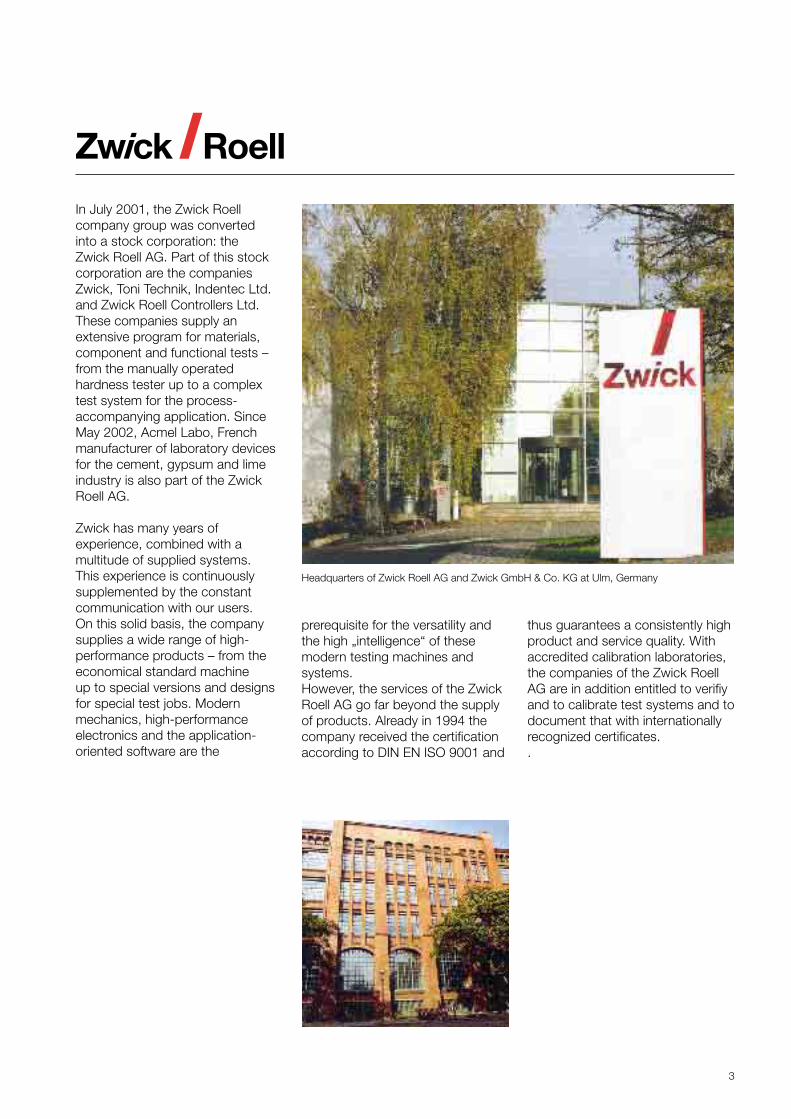
Headquarters of Zwick Roell AG and Zwick GmbH & Co. KG at Ulm, Germany
4
Table: Comparison of specific material properties
Material properties Metals Concrete Plastic mat.(without extreme values) (non-reinforc.)• Tensile and compr. strength, MPa 100 ... 2000 200 ... 500 20 ... 160• Young´s modulus, GPa 70 ... 210 15 ... 40 0.06 ... 6• Density (specific weigth), g/cm³ 2.7 ... 7.8 2.1 ... 2.4 1 ... 2
Metals – Applicationand properties
Metallic materials – metals andmetal alloys – have a very largespectrum of properties. In additionto the two characteristic featuresof structure and function, adifference is also made betweenstructural and constructionalmaterials (e.g. materials formechanical engineering andterotechnology, precisionmechanics and engineering) andfunctional materials (e.g. materialsfor electrical engineering,electronics and communicationmedia engineering).
Decisive for constructional materialsare the mechanical propertiesstrength, ridigity (elasticity) anddeformability (plasticity) at a giventemperature. These propertiesdefine the configuration (e.g. max.test force required for load frameand load cells) and the equipment(e.g. high-resolution extensometersfor the determination of the Young’smodulus of elasticity) of the testingmachines.
In case of a mechanical stresse.g. of steel, first – as opposedto rubber for example – the highrigidity immediately takes effect.This means considerable forceincreases with very littledeformations, often less than thethickness of a hair, and an elasticresilience during the reduction inforce. Only if the force continuesto increase, then a plastic, i.e.permanent deformation isoverruling the elastic deformation.
Specimens made of very brittlematerials (e.g. cast iron) or softsteel subject to low temperaturesbreak all of a sudden and nearlywithout any plastic deformationonce having reached the tensilestrength (i.e. without prior necking).
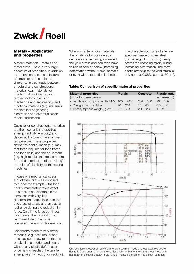
When using tenacious materials,the (local) rigidity considerablydecreases once having exceededthe yield stress and can even havevalues of zero or below (increasingdeformation without force increaseor even with a reduction in force).
The characteristic curve of a tensilespecimen made of sheet steel(gauge length L0 = 80 mm) clearlyproves the changing rigidity duringincreasing deformation. The mereelastic strain up to the yield stress isonly approx. 0.06% (approx. 50 µm),
Characteristic stress/strain curve of a tensile specimen made of sheet steel (see aboveillustration) and enlargement of the section until shortly after the 0.2 %-proof stress withillustration of the local gradient T via “virtual” measuring channel (see below illustration)
5
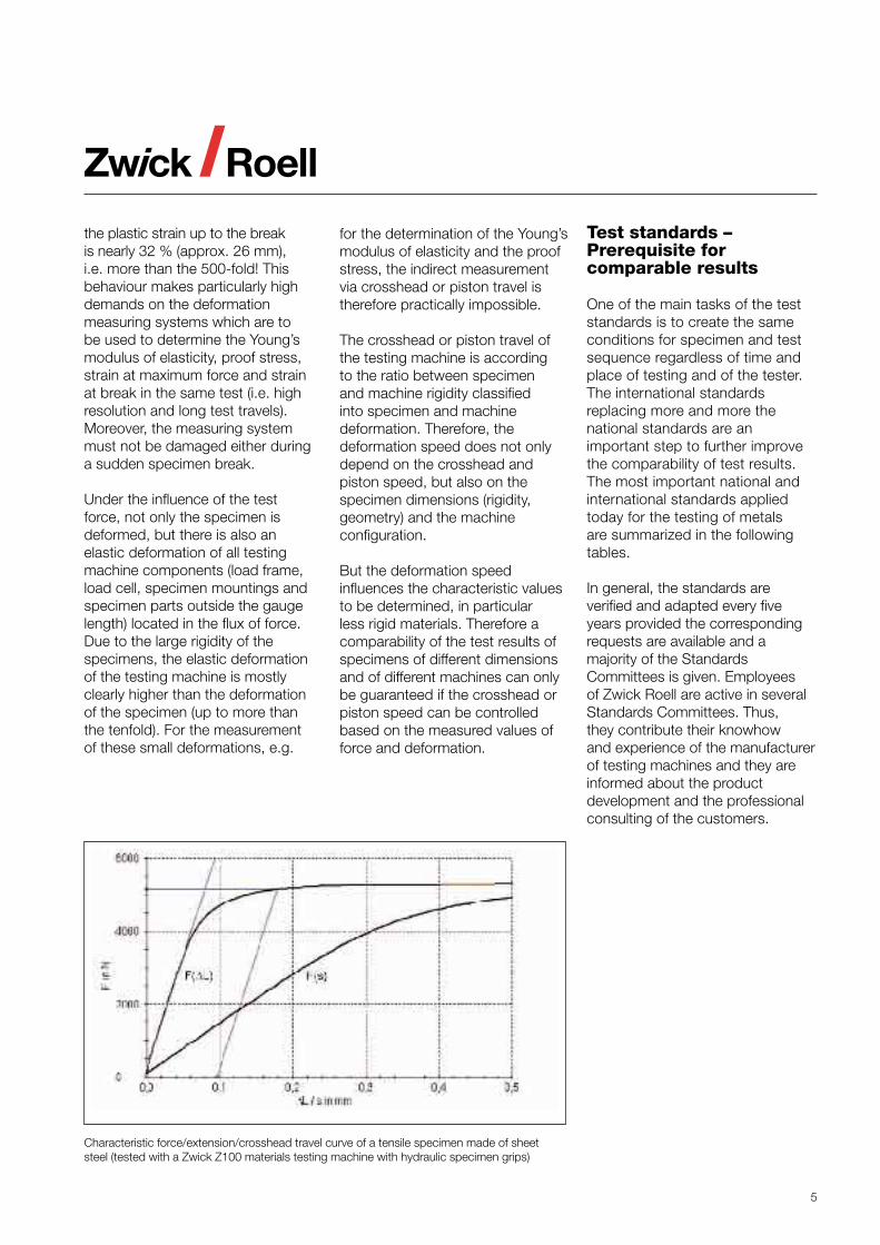
the plastic strain up to the breakis nearly 32 % (approx. 26 mm),i.e. more than the 500-fold! Thisbehaviour makes particularly highdemands on the deformationmeasuring systems which are tobe used to determine the Young’smodulus of elasticity, proof stress,strain at maximum force and strainat break in the same test (i.e. highresolution and long test travels).Moreover, the measuring systemmust not be damaged either duringa sudden specimen break.
Under the influence of the testforce, not only the specimen isdeformed, but there is also anelastic deformation of all testingmachine components (load frame,load cell, specimen mountings andspecimen parts outside the gaugelength) located in the flux of force.Due to the large rigidity of thespecimens, the elastic deformationof the testing machine is mostlyclearly higher than the deformationof the specimen (up to more thanthe tenfold). For the measurementof these small deformations, e.g.
Test standards –Prerequisite forcomparable results
One of the main tasks of the teststandards is to create the sameconditions for specimen and testsequence regardless of time andplace of testing and of the tester.The international standardsreplacing more and more thenational standards are animportant step to further improvethe comparability of test results.The most important national andinternational standards appliedtoday for the testing of metalsare summarized in the followingtables.
In general, the standards areverified and adapted every fiveyears provided the correspondingrequests are available and amajority of the StandardsCommittees is given. Employeesof Zwick Roell are active in severalStandards Committees. Thus,they contribute their knowhowand experience of the manufacturerof testing machines and they areinformed about the productdevelopment and the professionalconsulting of the customers.
Characteristic force/extension/crosshead travel curve of a tensile specimen made of sheetsteel (tested with a Zwick Z100 materials testing machine with hydraulic specimen grips)
for the determination of the Young’smodulus of elasticity and the proofstress, the indirect measurementvia crosshead or piston travel istherefore practically impossible.
The crosshead or piston travel ofthe testing machine is accordingto the ratio between specimenand machine rigidity classifiedinto specimen and machinedeformation. Therefore, thedeformation speed does not onlydepend on the crosshead andpiston speed, but also on thespecimen dimensions (rigidity,geometry) and the machineconfiguration.
But the deformation speedinfluences the characteristic valuesto be determined, in particularless rigid materials. Therefore acomparability of the test results ofspecimens of different dimensionsand of different machines can onlybe guaranteed if the crosshead orpiston speed can be controlledbased on the measured values offorce and deformation.
6
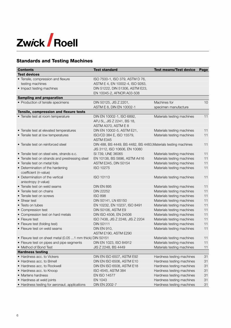
Standards and Testing Machines
Contents Test standard Test means/Test device PageTest devices• Tensile, compression and flexure ISO 7500-1, ISO 379, ASTM D 76,
testing machines ASTM E 4, EN 10002-4, ISO 9283,• Impact testing machines DIN 51222, DIN 51306, ASTM E23,
EN 10045-2, AFNOR A03-508Sampling and preparation• Production of tensile specimens DIN 50125, JIS Z 2201, Machines for 10
ASTM E 8, DIN EN 10002-1 specimen manufactureTensile, compression and flexure tests• Tensile test at room temperature DIN EN 10002-1, ISO 6892, Materials testing machines 11
APJ 5L, JIS Z 2241, BS 18,ASTM A370, ASTM E 8
• Tensile test at elevated temperatures DIN EN 10002-5, ASTM E21, Materials testing machines 11• Tensile test at low temperatures ISO/CD 384 E, ISO 15579, Materials testing machines 11
ASTM E345• Tensile test on reinforced steel DIN 488, BS 4449, BS 4482, BS 4483,Materials testing machines 11
JIS 3112, ISO 10606, EN 10080• Tensile test on steel wire, strands e.c. SI 739, UNE 36065 Materials testing machines 11• Tensile test on strands and prestressing steel EN 10138, BS 5896, ASTM A416 Materials testing machines 11• Tensile test on metal foils ASTM E345, DIN 50154 Materials testing machines 11• Determination of the hardening ISO 10275 Materials testing machines 11
coefficient (n-value)• Determination of the vertical ISO 10113 Materials testing machines 11
anisotropy (r-value)• Tensile test on weld seams DIN EN 895 Materials testing machines 11• Tensile test on chains DIN 22252 Materials testing machines 11• Tensile test on screws ISO 898 Materials testing machines 11• Shear test DIN 50141, LN 65150 Materials testing machines 11• Tests on tubes EN 10232, EN 10237, ISO 8491 Materials testing machines 11• Compression test DIN 50106, ASTM E9 Materials testing machines 11• Compression test on hard metals DIN ISO 4506, EN 24506 Materials testing machines 11• Flexure test ISO 7438, JIS Z 2248, JIS Z 2204 Materials testing machines 11• Flexure test (folding test) DIN 50111 Materials testing machines 11• Flexure test on weld seams DIN EN 910, Materials testing machines 11
ASTM E190, ASTM E290• Flexure test on sheet metal (0.05 ...1 mm thick) DIN 50151 Materials testing machines 11• Flexure test on pipes and pipe segments DIN EN 1023, ISO 84912 Materials testing machines 11• Method of Bond Test JIS Z 2248, BS 4449 Materials testing machines 11Hardness testing• Hardness acc. to Vickers DIN EN ISO 6507, ASTM E92 Hardness testing machines 31• Hardness acc. to Brinell DIN EN ISO 6506, ASTM E10 Hardness testing machines 31• Hardness acc. to Rockwell DIN EN ISO 6508, ASTM E18 Hardness testing machines 31• Hardness acc. to Knoop ISO 4545, ASTM 384 Hardness testing machines 31• Martens hardness EN ISO 14577 Hardness testing machines 31• Hardness at weld joints EN 1043 Hardness testing machines 31• Hardness testing for aeronaut. applications DIN EN 2002-7 Hardness testing machines 31
7
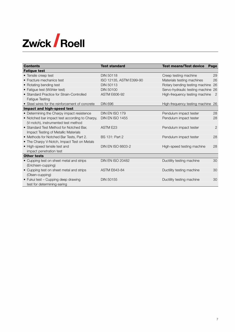
Contents Test standard Test means/Test device PageFatigue test• Tensile creep test DIN 50118 Creep testing machine 29• Fracture mechanics test ISO 12135, ASTM E399-90 Materials testing machines 26• Rotating bending test DIN 50113 Rotary bending testing machine 26• Fatigue test (Wöhler test) DIN 50100 Servo-hydraulic testing machine 26• Standard Practice for Strain-Controlled ASTM E606-92 High-frequency testing machine 2
Fatigue Testing• Steel wires for the reinforcement of concrete DIN 696 High-frequency testing machine 26Impact and high-speed test• Determining the Charpy impact resistence DIN EN ISO 179 Pendulum impact tester 28• Notched bar impact test according to Charpy, DIN EN ISO 1455 Pendulum impact tester 28
(V-notch), instrumented test method• Standard Test Method for Notched Bar, ASTM E23 Pendulum impact tester 2
Impact Testing of Metallic Materials• Methods for Notched Bar Tests, Part 2. BS 131: Part 2 Pendulum impact tester 28• The Charpy V-Notch, Impact Test on Metals• High-speed tensile test and DIN EN ISO 6603-2 High-speed testing machine 28
impact penetration testOther tests• Cupping test on sheet metal and strips DIN EN ISO 20482 Ductility testing machine 30
(Erichsen-cupping)• Cupping test on sheet metal and strips ASTM E643-84 Ductility testing machine 30
(Olsen-cupping)• Fukui test – Cupping deep drawing DIN 50155 Ductility testing machine 30
test for determining earing
8
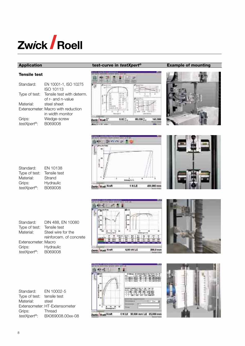
Application test-curve in testXpert® Example of mounting
Tensile test
Standard: EN 10001-1, ISO 10275ISO 10113
Type of test: Tensile test with determ.of r- and n-value
Material: steel sheetExtensometer: Macro with reduction
in width monitorGrips: Wedge-screwtestXpert®: B069008
Standard: EN 10138Type of test: Tensile testMaterial: StrandGrips: HydraulictestXpert®: B069008
Standard: DIN 488, EN 10080Type of test: Tensile testMaterial: Steel wire for the
reinforcem. of concreteExtensometer: MacroGrips: HydraulictestXpert®: B069008
Standard: EN 10002-5Type of test: tensile testMaterial: steelExtensometer: HT-ExtensometerGrips: ThreadtestXpert®: BX069008.00xx-08
9
Application test-curve in testXpert® Example of mounting
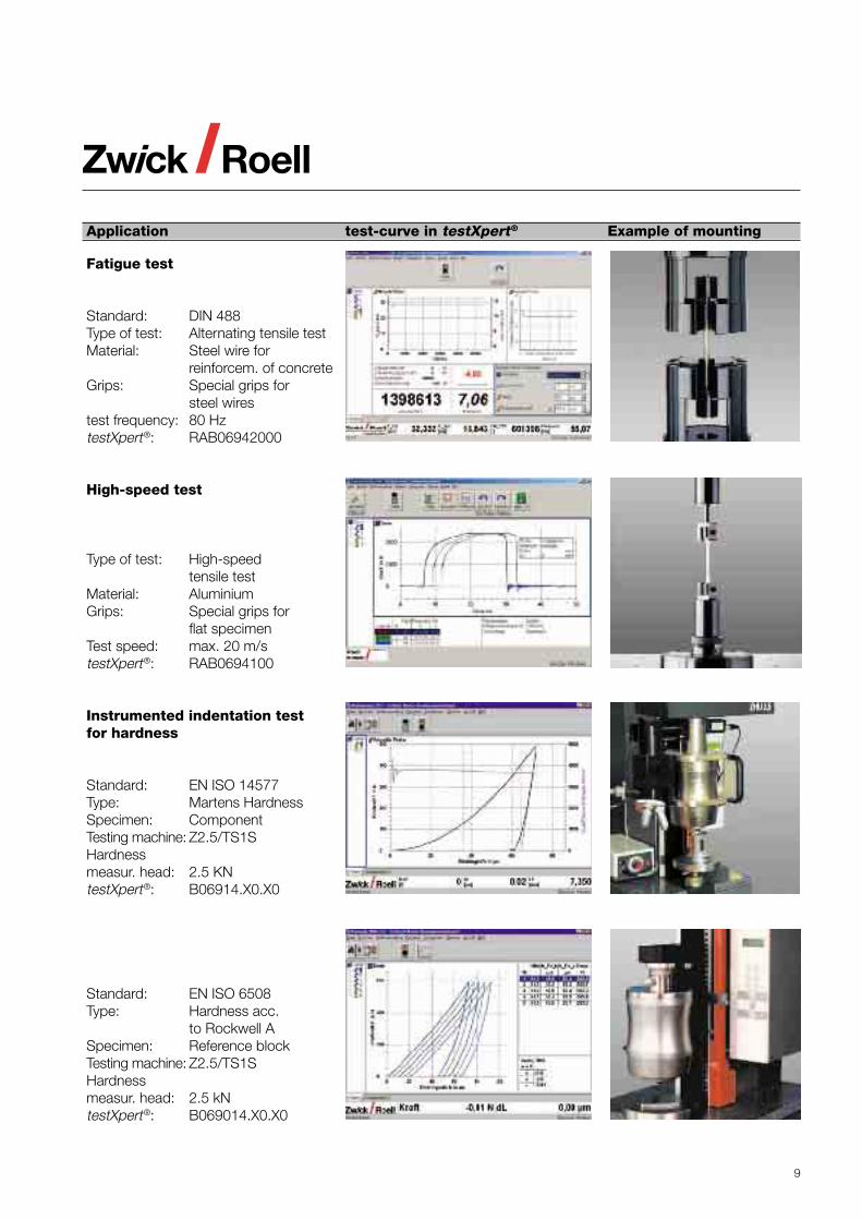
Fatigue test
Standard: DIN 488Type of test: Alternating tensile testMaterial: Steel wire for
reinforcem. of concreteGrips: Special grips for
steel wirestest frequency: 80 HztestXpert®: RAB06942000
High-speed test
Type of test: High-speedtensile test
Material: AluminiumGrips: Special grips for
flat specimenTest speed: max. 20 m/stestXpert®: RAB0694100
Instrumented indentation testfor hardness
Standard: EN ISO 14577Type: Martens HardnessSpecimen: ComponentTesting machine: Z2.5/TS1SHardnessmeasur. head: 2.5 KNtestXpert®: B06914.X0.X0
Standard: EN ISO 6508Type: Hardness acc.
to Rockwell ASpecimen: Reference blockTesting machine: Z2.5/TS1SHardnessmeasur. head: 2.5 kNtestXpert®: B069014.X0.X0
10
Specimen blanking presses for cutting force from 200 to 1.500 kN
Series/Type RZ50 RZ65 RZ100 RZ150Structural shape C - frame O-frame O-frame O-frameCutting force, kN 500 650 1,000 1,500Specim. throughput, 1/min 6 6 6 6Specim.thickness, mm 0.2 - 6 0.2 - 6 0.2 - 6 0.2 - 8Max. power cons., kVA 4 4 4 10
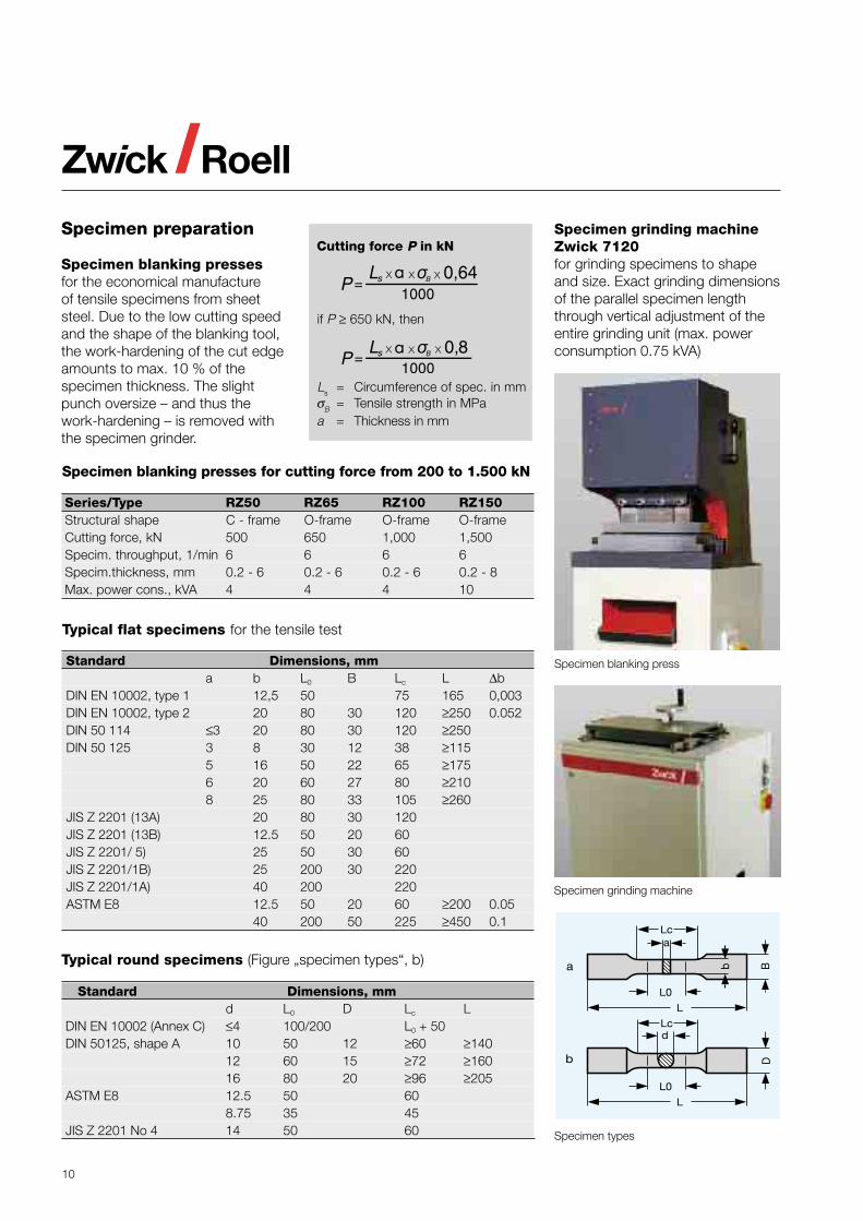
Specimen preparation
Specimen blanking pressesfor the economical manufactureof tensile specimens from sheetsteel. Due to the low cutting speedand the shape of the blanking tool,the work-hardening of the cut edgeamounts to max. 10 % of thespecimen thickness. The slightpunch oversize – and thus thework-hardening – is removed withthe specimen grinder.
Specimen grinding machineZwick 7120for grinding specimens to shapeand size. Exact grinding dimensionsof the parallel specimen lengththrough vertical adjustment of theentire grinding unit (max. powerconsumption 0.75 kVA)
Typical round specimens (Figure „specimen types“, b)
Standard Dimensions, mmd L0 D Lc L
DIN EN 10002 (Annex C) ≤4 100/200 L0 + 50DIN 50125, shape A 10 50 12 ≥60 ≥140
12 60 15 ≥72 ≥16016 80 20 ≥96 ≥205
ASTM E8 12.5 50 608.75 35 45
JIS Z 2201 No 4 14 50 60
Typical flat specimens for the tensile test
Standard Dimensions, mma b L0 B Lc L ∆b
DIN EN 10002, type 1 12,5 50 75 165 0,003DIN EN 10002, type 2 20 80 30 120 ≥250 0.052DIN 50 114 ≤3 20 80 30 120 ≥250DIN 50 125 3 8 30 12 38 ≥115
5 16 50 22 65 ≥1756 20 60 27 80 ≥2108 25 80 33 105 ≥260
JIS Z 2201 (13A) 20 80 30 120JIS Z 2201 (13B) 12.5 50 20 60JIS Z 2201/ 5) 25 50 30 60JIS Z 2201/1B) 25 200 30 220JIS Z 2201/1A) 40 200 220ASTM E8 12.5 50 20 60 ≥200 0.05
40 200 50 225 ≥450 0.1
Specimen blanking press
Specimen grinding machine
Specimen types
Cutting force P in kN
if P ≥ 650 kN, then
Ls = Circumference of spec. in mmσB = Tensile strength in MPaa = Thickness in mm
11
Materials TestingMachines
Field of application
Materials testing machines arepredominantly used for thedetermination of the strength anddeformation behaviour of specimensand components. For this purpose,tensile, compression, flexure orshear tests and with special deviceseven torsion tests are carried out.These testing machines have largetest areas, test travels, speedranges, exchangeable test tools andtest data transducers etc. to enabletests to be carried out both onspecimens and components ofdifferent shapes and dimensionsmade of most different materialsand material combinations and ofdifferent properties.
Basic concept
The Zwick program includes testingmachines in table-top and floorstanding design with differentmeasurement and control systems,load frames, drives and versatilefunction and supplementary units.
However in order to be able to offerthe best machine for eachrequirement, Zwick has developed auser-related concept. The user canchoose among three machine lines,each of them being completelydifferent as to equipment,performance features and also asto the capability of expansion:• BasicLine• Standard Line• Allround Line
The decisive testing machinecomponent is the measurement andcontrol system. Its conception andits scope of performance decidewhich drive can be controlled, whichmeasurement sytem can beconnected to it and which functions
can be controlled with it – and theythus determine the range ofapplication and the testing machine’scapability for future expansion.
The advantages to the user ofthe three different testing machineversions are as follows:• The BasicLine is particularly
suitable for function tests oncomponent parts and for thesimple materials test.
• The Standard Line is ideal to solvesimple test jobs reliably. It is alow-cost, sturdy solution whichcovers many testing needs.
• The Allround Line is the basis fora large spectrum of demandingtest jobs and can easily beexpanded with the requirementsbecoming more demanding. It isthus a solution that can be reliedon for future requirements.
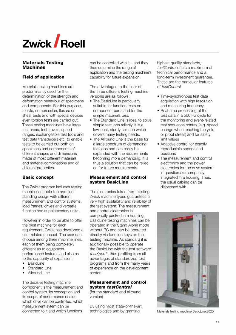
Measurement and controlsystem BasicLine
The electronics taken from existingZwick machine types guarantees avery high availability and reliability ofthe test system. The measurementand control electronics iscompactly packed in a housing.BasicLine testing machines can beoperated in the Stand Alone modewithout PC and can be operateddirectly via function keys on thetesting machine. As standard it isadditionally possible to operatethe BasicLine with the test softwaretestXpert®, thus profiting from alladvantages of standardized testprograms and from the many yearsof experience on the developmentsector.
Measurement and controlsystem testControl(for the standard and allroundversion)
By using most state-of-the-arttechnologies and by granting
highest quality standards,testControl offers a maximum oftechnical performance and along-term investment guarantee.These are the particular featuresof testControl:
• Time-synchronous test dataacquisition with high resolutionand measuring frequency
• Real-time processing of thetest data in a 500 Hz cycle forthe monitoring and event-relatedtest sequence control (e.g. speedchange when reaching the yieldor proof stress) and for safetylimit values
• Adaptive control for exactlyreproducible speeds andpositions
• The measurement and controlelectronics and the powerelectronics for the drive systemin question are compactlyintegrated in a housing. Thus,the usual cabling can bedispensed with.
Materials testing machine BasicLine Z020
12
The measurement and controlsystem testControl is availablein 2 variants:
Stand Alone Variant
Easy and reliable operation viacoloured display, 10-key keyboardand a few function keys – withoutPC. A printer may be connecteddirectly for the printout of testresults.
PC-Variant
The system may be configuredand expanded to cope with themost different applications. PCand user software testXpert® makeapplications very comfortable andextremely flexible.
Load frames
Different load frame versions for testloads up to 2.000 kN are available asstandard. For special applications,special versions can be developedand manufactured, e.g. load framesin horizontal position suitable for thetesting of long steel ropes.
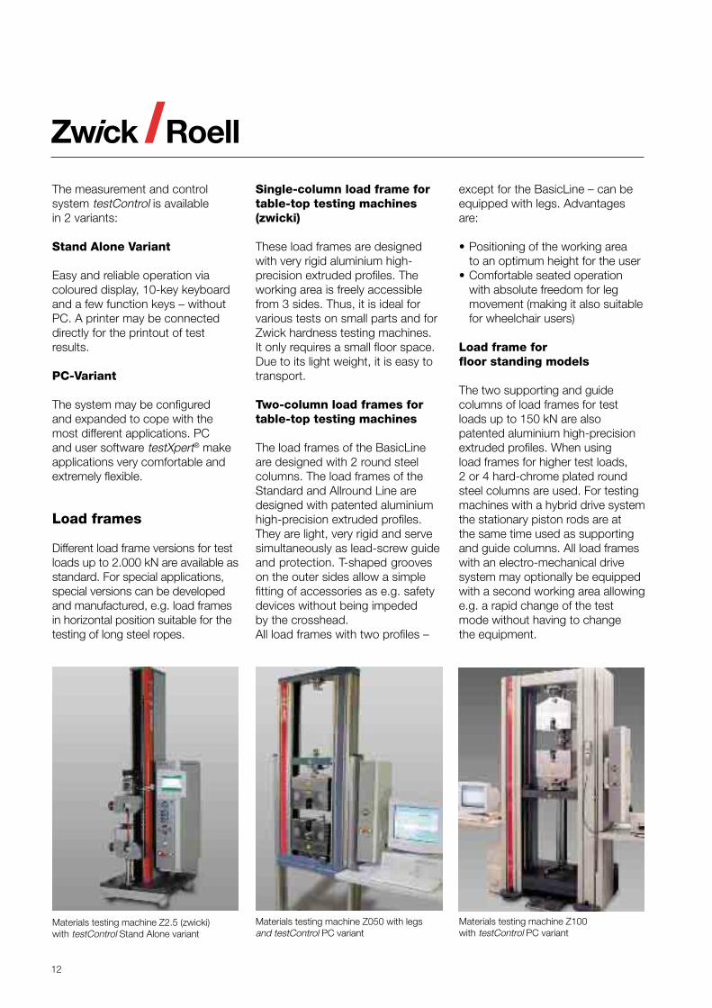
Single-column load frame fortable-top testing machines(zwicki)
These load frames are designedwith very rigid aluminium high-precision extruded profiles. Theworking area is freely accessiblefrom 3 sides. Thus, it is ideal forvarious tests on small parts and forZwick hardness testing machines.It only requires a small floor space.Due to its light weight, it is easy totransport.
Two-column load frames fortable-top testing machines
The load frames of the BasicLineare designed with 2 round steelcolumns. The load frames of theStandard and Allround Line aredesigned with patented aluminiumhigh-precision extruded profiles.They are light, very rigid and servesimultaneously as lead-screw guideand protection. T-shaped grooveson the outer sides allow a simplefitting of accessories as e.g. safetydevices without being impededby the crosshead.All load frames with two profiles –
except for the BasicLine – can beequipped with legs. Advantagesare:
• Positioning of the working areato an optimum height for the user
• Comfortable seated operationwith absolute freedom for legmovement (making it also suitablefor wheelchair users)
Load frame forfloor standing models
The two supporting and guidecolumns of load frames for testloads up to 150 kN are alsopatented aluminium high-precisionextruded profiles. When usingload frames for higher test loads,2 or 4 hard-chrome plated roundsteel columns are used. For testingmachines with a hybrid drive systemthe stationary piston rods are atthe same time used as supportingand guide columns. All load frameswith an electro-mechanical drivesystem may optionally be equippedwith a second working area allowinge.g. a rapid change of the testmode without having to changethe equipment.
Materials testing machine Z2.5 (zwicki)with testControl Stand Alone variant
Materials testing machine Z050 with legsand testControl PC variant
Materials testing machine Z100with testControl PC variant
13
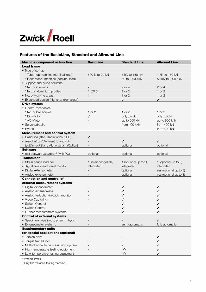
Machine component or function BasicLine Standard Line Allround LineLoad frame• Type of set-up
* Table-top machine (nominal load) 500 N to 20 kN 1 kN to 150 kN 1 kN to 150 kN* Floor stand. machine (nominal load) - 50 to 2.000 kN 50 kN to 2.000 kN
• Support and guide columns* No. of columns 2 2 or 4 2 or 4* No. of aluminium profiles 1 (Z0.5) 1 or 2 1 or 2
• No. of working areas 1 1 or 2 1 or 2• Expanded design (higher and/or larger) -Drive system• Electro-mechanical
* No. of ball screws 1 or 2 1 or 2 1 or 2* DC-Motor only zwicki only zwicki* AC-Motor - up to 600 kN1) up to 600 kN1)
• Servohydraulic - from 400 kN2) from 400 kN• Hybrid - - from 400 kNMeasurement and control system• BasicLine (also usable without PC) - -• testControl PC-variant (Standard) -
testControl Stand Alone variant (Option) - optional optionalSoftware• test software testXpert® (with PC) optional optional optionalTransducer• Strain gauge load cell 1 (interchangeable) 1 (optional up to 2) 1 (optional up to 3)• Digital crosshead travel monitor integrated integrated integrated• Digital extensometer - optional 1 yes (optional up to 3)• Analog extensometer - optional 1 yes (optional up to 3)Connection and control ofexternal measurement systems• Digital extensometer -• Analog extensometer -• Analog reduction-in-width monitor -• Video Capturing -• Switch Contact -• Switch Control -• Further measurement systems -Control of external systems• Specimen grips (mot., pneum., hydr.) - -• Extensometer systems - semi-automatic fully automaticSupplementary unitsfor special applications (optional)• Torsion drive - -• Torque transducer - -• Multi-channel force measuring system - -• High-temperature testing equipment - ( )• Low-temperature testing equipment - ( )1) Without zwicki2) Only SP-matarials testing machine
Features of the BasicLine, Standard and Allround Line
14
Load frames and drive systems of the BasicLine
Series Z0.5 Z005 Z010 Z020• Type table top table top table top table top• Max. load, kN 0.5 5 10 20• Working area, max.
* Height, mm 596 561/1.061 1,041 1.041* Width, mm no limit 420 420 420* Depth, mm 99.5 no limit no limit no limit
• Max. crosshead speed, mm/min 1.500 500 1.000 500• Crosshead travel resolution, µm 0.226 0.05 0.09 0.045• Max. power consumption, kVA 0.4 0.6 0.6 0.6
Drives
Electro-mechanical drivesystems
The basis of all electro-mechanicaldrive systems are backlash-freeand low-friction ball screws anddigitally controlled drive systems.They are used with load frames fortest loads up to 600 kN. Togetherwith the digital measurement andcontrol system they offer thefollowing advantages:
• Extremely high, stepless speedrange
• Very low speeds adjustable(from about 0.5 µm/min on)
• High-precision and exactlyreproducible positions andspeeds
The testing machines designedwith single-column load frames(zwicki and BasicLine) areequipped with low-cost d.c. drives,all the others with particularly low-inertia, brushless three-phasedrives.
Hydraulic drive systems
This drive unit is located centrallyon the upper fixed crosshead.Thus, the test area lying beneathis easily accessible. A servo- orproportional valve regulates the
oil flow between hydraulic unitand differential cylinder. The oilcushion in the upper pressure areaavoids the „piston jump“ the ramsare known for after the specimenbreak. The resolution of the pistontravel transducer is 1.25 µm (lessthan 1/400.000 of the max. testtravel). The hydraulic drive unitis the most economic solutionparticularly for high test loads.
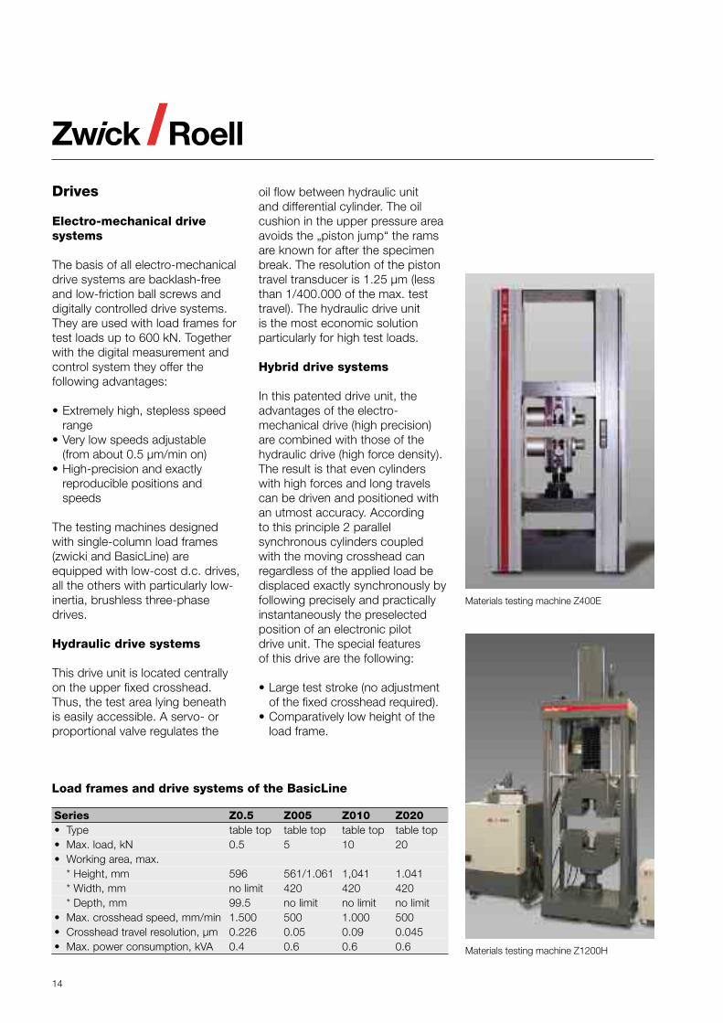
Hybrid drive systems
In this patented drive unit, theadvantages of the electro-mechanical drive (high precision)are combined with those of thehydraulic drive (high force density).The result is that even cylinderswith high forces and long travelscan be driven and positioned withan utmost accuracy. Accordingto this principle 2 parallelsynchronous cylinders coupledwith the moving crosshead canregardless of the applied load bedisplaced exactly synchronously byfollowing precisely and practicallyinstantaneously the preselectedposition of an electronic pilotdrive unit. The special featuresof this drive are the following:
• Large test stroke (no adjustmentof the fixed crosshead required).
• Comparatively low height of theload frame.
Materials testing machine Z400E
Materials testing machine Z1200H
15
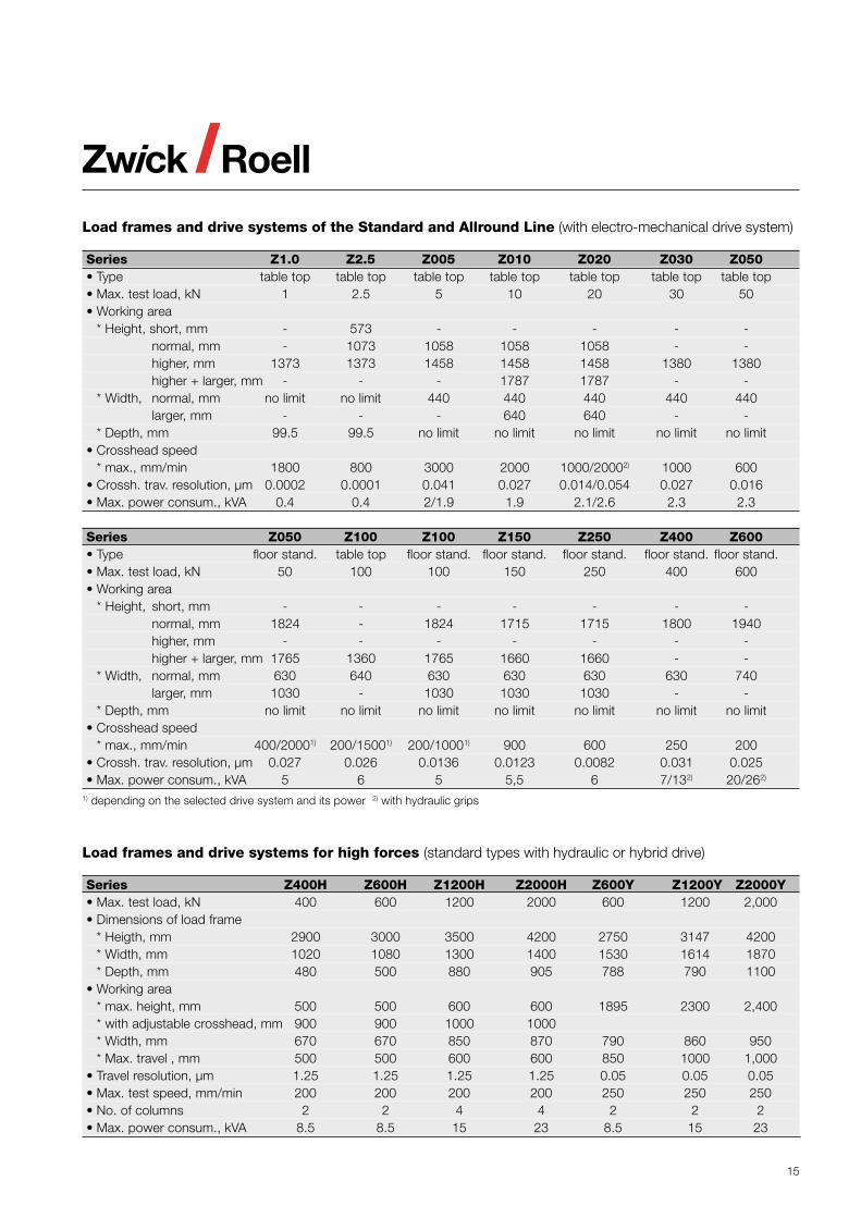
Load frames and drive systems of the Standard and Allround Line (with electro-mechanical drive system)
Series Z1.0 Z2.5 Z005 Z010 Z020 Z030 Z050• Type table top table top table top table top table top table top table top• Max. test load, kN 1 2.5 5 10 20 30 50• Working area
* Height, short, mm - 573 - - - - -normal, mm - 1073 1058 1058 1058 - -higher, mm 1373 1373 1458 1458 1458 1380 1380higher + larger, mm - - - 1787 1787 - -
* Width, normal, mm no limit no limit 440 440 440 440 440larger, mm - - - 640 640 - -
* Depth, mm 99.5 99.5 no limit no limit no limit no limit no limit• Crosshead speed
* max., mm/min 1800 800 3000 2000 1000/20002) 1000 600• Crossh. trav. resolution, µm 0.0002 0.0001 0.041 0.027 0.014/0.054 0.027 0.016• Max. power consum., kVA 0.4 0.4 2/1.9 1.9 2.1/2.6 2.3 2.3
Series Z050 Z100 Z100 Z150 Z250 Z400 Z600• Type floor stand. table top floor stand. floor stand. floor stand. floor stand. floor stand.• Max. test load, kN 50 100 100 150 250 400 600• Working area
* Height, short, mm - - - - - - -normal, mm 1824 - 1824 1715 1715 1800 1940higher, mm - - - - - - -higher + larger, mm 1765 1360 1765 1660 1660 - -
* Width, normal, mm 630 640 630 630 630 630 740larger, mm 1030 - 1030 1030 1030 - -
* Depth, mm no limit no limit no limit no limit no limit no limit no limit• Crosshead speed
* max., mm/min 400/20001) 200/15001) 200/10001) 900 600 250 200• Crossh. trav. resolution, µm 0.027 0.026 0.0136 0.0123 0.0082 0.031 0.025• Max. power consum., kVA 5 6 5 5,5 6 7/132) 20/262)
1) depending on the selected drive system and its power 2) with hydraulic grips
Load frames and drive systems for high forces (standard types with hydraulic or hybrid drive)
Series Z400H Z600H Z1200H Z2000H Z600Y Z1200Y Z2000Y• Max. test load, kN 400 600 1200 2000 600 1200 2,000• Dimensions of load frame
* Heigth, mm 2900 3000 3500 4200 2750 3147 4200* Width, mm 1020 1080 1300 1400 1530 1614 1870* Depth, mm 480 500 880 905 788 790 1100
• Working area* max. height, mm 500 500 600 600 1895 2300 2,400* with adjustable crosshead, mm 900 900 1000 1000* Width, mm 670 670 850 870 790 860 950* Max. travel , mm 500 500 600 600 850 1000 1,000
• Travel resolution, µm 1.25 1.25 1.25 1.25 0.05 0.05 0.05• Max. test speed, mm/min 200 200 200 200 250 250 250• No. of columns 2 2 4 4 2 2 2• Max. power consum., kVA 8.5 8.5 15 23 8.5 15 23
16
SP-testing machines with hydraulic drive system for nominal loads from 400 to 2000 kN
Series SP400.xx SP600.xx SP1000.xx SP1200.xx SP1500.xx SP2000.xx• Max. load, kN 400 600 1000 1200 1500 2000• Working area
* Height, mm (.00)1) 100-600 100-600 120-720 120-720 120-720 120-720* Height, mm (.01)2) 0-800 0-800 0-900 0-1000 0-1000 0-1000* Width, mm 670 670 700 850 850 850
• Max. travel, mm 500 500 600 600 600 600• Travel resolution, µm 5 5 5 5 5 5• Max. test speed, mm/min 250 200 200 200 200 200• No. of columns 2 2 4 4 4 4• Max. power consumption, kVA 10 10 18 18 18 30
1) with fixed crosshead 2) with adjustable crosshead
Compression testing devices for SP testing machines for max. test loads from 400 to 2000 kN
Series/type X070220 X070220 X070220 X070220 X070220 X070220-194 -210 -226 -240 -254 -268
• Max. test load, kN 400 600 1000 1200 1500 2000• Diameter, mm 230 230 300 300 300 300
Flexure test devices for SP testing machines for maximum test loads from 400 to 2000 kNExample: support radius 25 mm, support separation 30 to 600 mm, support height 100 mm, flexure fin height 200 mm
Series/type X070220 X070220 X070220 X070220 X070220 X070220-196 -212 -228 -242 -256 -270
• Max. test load, kN 400 600 1000 1200 1500 2000• Flexure fin-Ø, mm1) 30,40,50 30,40,50 50 50 50 501) Separate order items
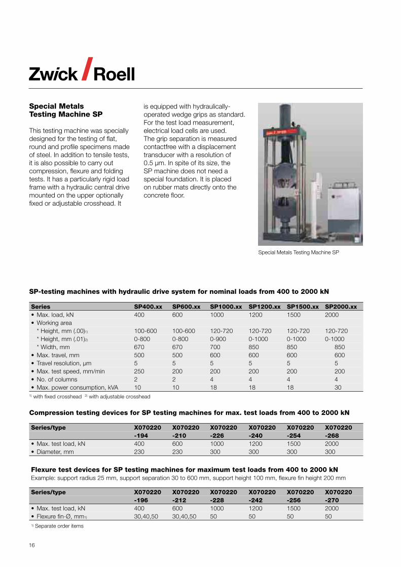
Special Metals Testing Machine SP
Special MetalsTesting Machine SP
This testing machine was speciallydesigned for the testing of flat,round and profile specimens madeof steel. In addition to tensile tests,it is also possible to carry outcompression, flexure and foldingtests. It has a particularly rigid loadframe with a hydraulic central drivemounted on the upper optionallyfixed or adjustable crosshead. It
is equipped with hydraulically-operated wedge grips as standard.For the test load measurement,electrical load cells are used.The grip separation is measuredcontactfree with a displacementtransducer with a resolution of0.5 µm. In spite of its size, theSP machine does not need aspecial foundation. It is placedon rubber mats directly onto theconcrete floor.
17
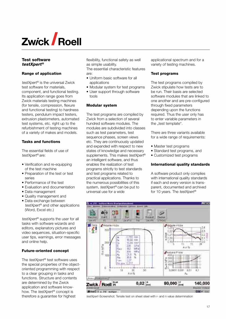
Test softwaretestXpert®
Range of application
testXpert® is the universal Zwicktest software for materials,component, and functional testing.Its application range goes fromZwick materials testing machines(for tensile, compression, flexureand functional testing) to hardnesstesters, pendulum impact testers,extrusion plastometers, automatedtest systems, etc. right up to therefurbishment of testing machinesof a variety of makes and models.
Tasks and functions
The essential fields of use oftestXpert® are:
• Verification and re-equippingof the test machine
• Preparation of the test or testseries
• Performance of the test• Evaluation and documentation• Data management• Quality management and• Data exchange between
testXpert® and other applications(Word, Excel etc.)
testXpert® supports the user for alltasks with software wizards andeditors, explanatory pictures andvideo sequences, situation-specificuser tips, warnings, error messagesand online help.
Future-oriented concept
The testXpert® test software usesthe special properties of the object-oriented programming with respectto a clear grouping in tasks andfunctions. Structure and contentsare determined by the Zwickapplication and software know-how. The testXpert® concept istherefore a guarantee for highest
flexibility, functional safety as wellas simple usability.The essential characteristic featuresare:• Uniform basic software for all
applications• Modular system for test programs• User support through software
tools
Modular system
The test programs are compiled byZwick from a selection of severalhundred software modules. Themodules are subdivided into classessuch as test parameters, testsequence phases, screen viewsetc. They are continuously updatedand expanded with respect to newstates of knowledge and necessarysupplements. This makes testXpert®
an intelligent software, and thusenables the realization of testprograms strictly to test standardsand test programs related topractical applications. Thanks tothe numerous possibilities of thissystem, testXpert® can be put touniversal use for a wide
applicational spectrum and for avariety of testing machines.
Test programs
The test programs compiled byZwick stipulate how tests are tobe run. Their basis are selectedsoftware modules that are linked toone another and are pre-configuredthrough fixed parametersdepending upon the functionsrequired. Thus the user only hasto enter variable parameters inthe „test template“.
There are three variants availablefor a wide range of requirements:
• Master test programs• Standard test programs, and• Customized test programs
International quality standards
A software product only complieswith international quality standardsif each and every version is trans-parent, documented and archivedfor 10 years. The testXpert®
testXpert-Screenshot: Tensile test on sheet steel with r- and n value determination
18
test software fully meets theserequirements and even theparticularly strict guidelines of theGood Manufacturing Practices(GMP).
The entire software developmentprocess and its components arediligently documented and archivedfrom the source code through tothe software tools used, for eachand every version. This is validfor each phase from analysis viaspecification, design andimplementation up to the test.Conformity to the standard ISO9000-3 for development oftestXpert® has been confirmed viaaudit report no. QM-F-96/1016.
Safety in detail
Windows software is normally usedin offices. However, testXpert®
takes over an additional andespecially critical task: themonitoring and controlling ofmachines. Machine damage andpotential danger to persons mustbe ruled out. That’s why testXpert®
doesn’t use any overlappingwindows in the test mode to avoidhiding important displays or keyfields.
Automatic acceptance ofsystem data
Different test jobs require differenttest machines with different andusually interchangeablecomponents. Their specificproperties are characterised bythe system data (nominal force,travel, speed range, mountingheight, calibration factors, etc.).Organisational data also belong tothe above, e.g. the series numberor the date of the last calibration.
testXpert® accepts these dataautomatically directly afterthe program start
• for the necessary settings• for the determination of safety
limit values• for the correct measurement
signal evaluation
Furthermore testXpert® checkswhether or not• the test can be carried out
with this configuration• all settings have been made• the data have changed for the
current test
Simplest operation
The operator’s effort is reducedto a one-button operation, i.e.activating the start button, forstandard applications. This ispossible because testXpert®
automatically records the test data,and dependent upon this, controlsand monitors the test sequenceand determines and documentsthe test results.
Preparation of a test series requiresonly two steps:• Call-up the test program foreseen
for the required application• Input or selection of variable
parameters
Optimum user information
All displays necessary for theperformance of a test and a testseries, can be grouped together ina clearand concise manner in one singlescreen setting.• Input fields for specimen-specific
test parameters• Curve diagram (single or multiple
curves)• Tables for test results• Tables for result statistics
Data backup for further use
Depending upon the preselection inthe test program, not only all
data but also selected result datafrom a test or test series canbe saved. The saving of all dataoffers the possibility of tracingthe origin of the result data up toconfiguration and settings for thetest machine. The standardizedmeasurement data, i.e. the dataconverted to its basic units canbe repeatedly displayed in thesimulation mode and can alsobe evaluated according to othercriteria.
Video Capturing
The test software testXpert® doesnot only support the user by meansof „Help“ videos. It is also possibleto carry out multimedia tests byusing a video camera and a video-capture card with the video picturesbeing recorded time-synchronouslywith the test data.
• With the cursor keys, a „videoreticle“ can be moved over thetest curve and the correspondingpicture can be displayed
• The pictures can be captured ata preselected distance of themeasuring points or independence on the event
• The video can also be playedalone, irrespective of the testingmachine
• Distances between two pointsand angles between three points,radii, diameters and areas canbe measured from the specimenin pictorial representation
• Optionally, the pictures can alsobe output with dimension linesand test data
19
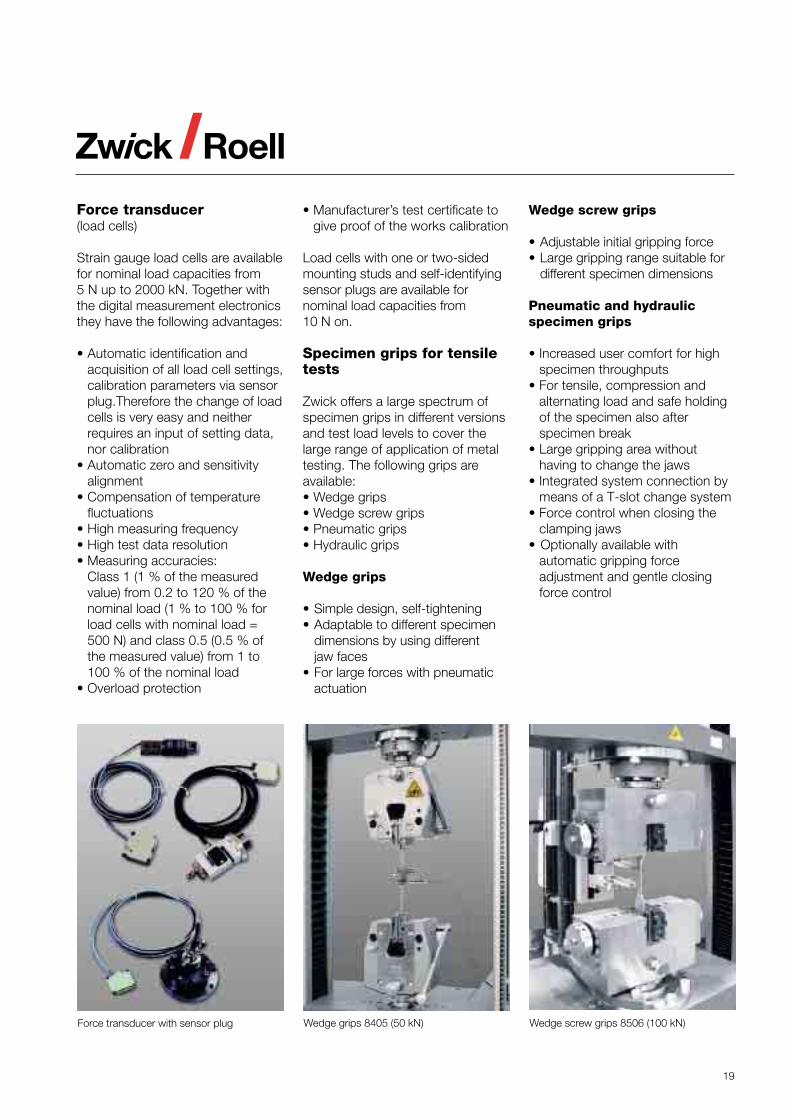
Force transducer(load cells)
Strain gauge load cells are availablefor nominal load capacities from5 N up to 2000 kN. Together withthe digital measurement electronicsthey have the following advantages:
• Automatic identification andacquisition of all load cell settings,calibration parameters via sensorplug.Therefore the change of loadcells is very easy and neitherrequires an input of setting data,nor calibration
• Automatic zero and sensitivityalignment
• Compensation of temperaturefluctuations
• High measuring frequency• High test data resolution• Measuring accuracies:
Class 1 (1 % of the measuredvalue) from 0.2 to 120 % of thenominal load (1 % to 100 % forload cells with nominal load =500 N) and class 0.5 (0.5 % ofthe measured value) from 1 to100 % of the nominal load
• Overload protection
• Manufacturer’s test certificate togive proof of the works calibration
Load cells with one or two-sidedmounting studs and self-identifyingsensor plugs are available fornominal load capacities from10 N on.
Specimen grips for tensiletests
Zwick offers a large spectrum ofspecimen grips in different versionsand test load levels to cover thelarge range of application of metaltesting. The following grips areavailable:• Wedge grips• Wedge screw grips• Pneumatic grips• Hydraulic grips
Wedge grips
• Simple design, self-tightening• Adaptable to different specimen
dimensions by using differentjaw faces
• For large forces with pneumaticactuation
Wedge screw grips
• Adjustable initial gripping force• Large gripping range suitable for
different specimen dimensions
Pneumatic and hydraulicspecimen grips
• Increased user comfort for highspecimen throughputs
• For tensile, compression andalternating load and safe holdingof the specimen also afterspecimen break
• Large gripping area withouthaving to change the jaws
• Integrated system connection bymeans of a T-slot change system
• Force control when closing theclamping jaws
• Optionally available withautomatic gripping forceadjustment and gentle closingforce control
Force transducer with sensor plug Wedge grips 8405 (50 kN) Wedge screw grips 8506 (100 kN)
20
Wedge screw grips for testing forces from 0.5 to 250 kN
Series/type 8106 8206 8306 8406 8406 8506 8506 8507• Max. testing force, kN 0.5 2.5 10 30 50 100 150 250• Max. spec. thickn., mm 5 10 30 30 30 30 30 64• Max. spec. diam., mm 30 30 30 30 30 30 30 80• Max. clamping surface
* Width, mm 15 30 60 60 60 60 60 80* Height, mm 30 60 60/80 60/80 80 80 80 100/120
• Operation manual manual manual manual manual/ manual/ manual/ manual/(opening/closing) motorized motorized motorized motorized
• Construction height, mm 64 110 125 137 146/147 176/177 176/177 252• Individual weight, kg 0.2 3 15 16 37/50 44/50 42/46 112
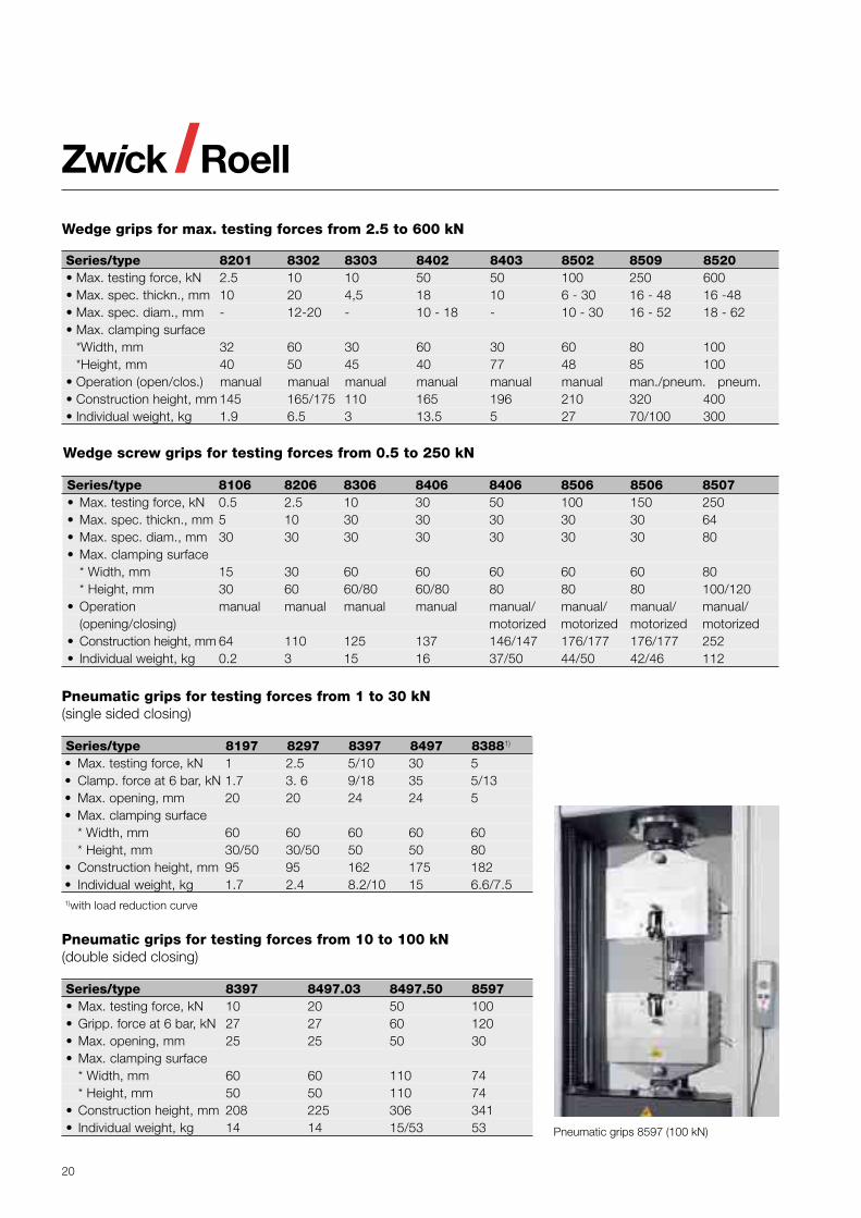
Pneumatic grips for testing forces from 1 to 30 kN(single sided closing)
Series/type 8197 8297 8397 8497 83881)
• Max. testing force, kN 1 2.5 5/10 30 5• Clamp. force at 6 bar, kN 1.7 3. 6 9/18 35 5/13• Max. opening, mm 20 20 24 24 5• Max. clamping surface
* Width, mm 60 60 60 60 60* Height, mm 30/50 30/50 50 50 80
• Construction height, mm 95 95 162 175 182• Individual weight, kg 1.7 2.4 8.2/10 15 6.6/7.51)with load reduction curve
Pneumatic grips for testing forces from 10 to 100 kN(double sided closing)
Series/type 8397 8497.03 8497.50 8597• Max. testing force, kN 10 20 50 100• Gripp. force at 6 bar, kN 27 27 60 120• Max. opening, mm 25 25 50 30• Max. clamping surface
* Width, mm 60 60 110 74* Height, mm 50 50 110 74
• Construction height, mm 208 225 306 341• Individual weight, kg 14 14 15/53 53
Wedge grips for max. testing forces from 2.5 to 600 kN
Series/type 8201 8302 8303 8402 8403 8502 8509 8520• Max. testing force, kN 2.5 10 10 50 50 100 250 600• Max. spec. thickn., mm 10 20 4,5 18 10 6 - 30 16 - 48 16 -48• Max. spec. diam., mm - 12-20 - 10 - 18 - 10 - 30 16 - 52 18 - 62• Max. clamping surface
*Width, mm 32 60 30 60 30 60 80 100*Height, mm 40 50 45 40 77 48 85 100
• Operation (open/clos.) manual manual manual manual manual manual man./pneum. pneum.• Construction height, mm 145 165/175 110 165 196 210 320 400• Individual weight, kg 1.9 6.5 3 13.5 5 27 70/100 300
Pneumatic grips 8597 (100 kN)
21
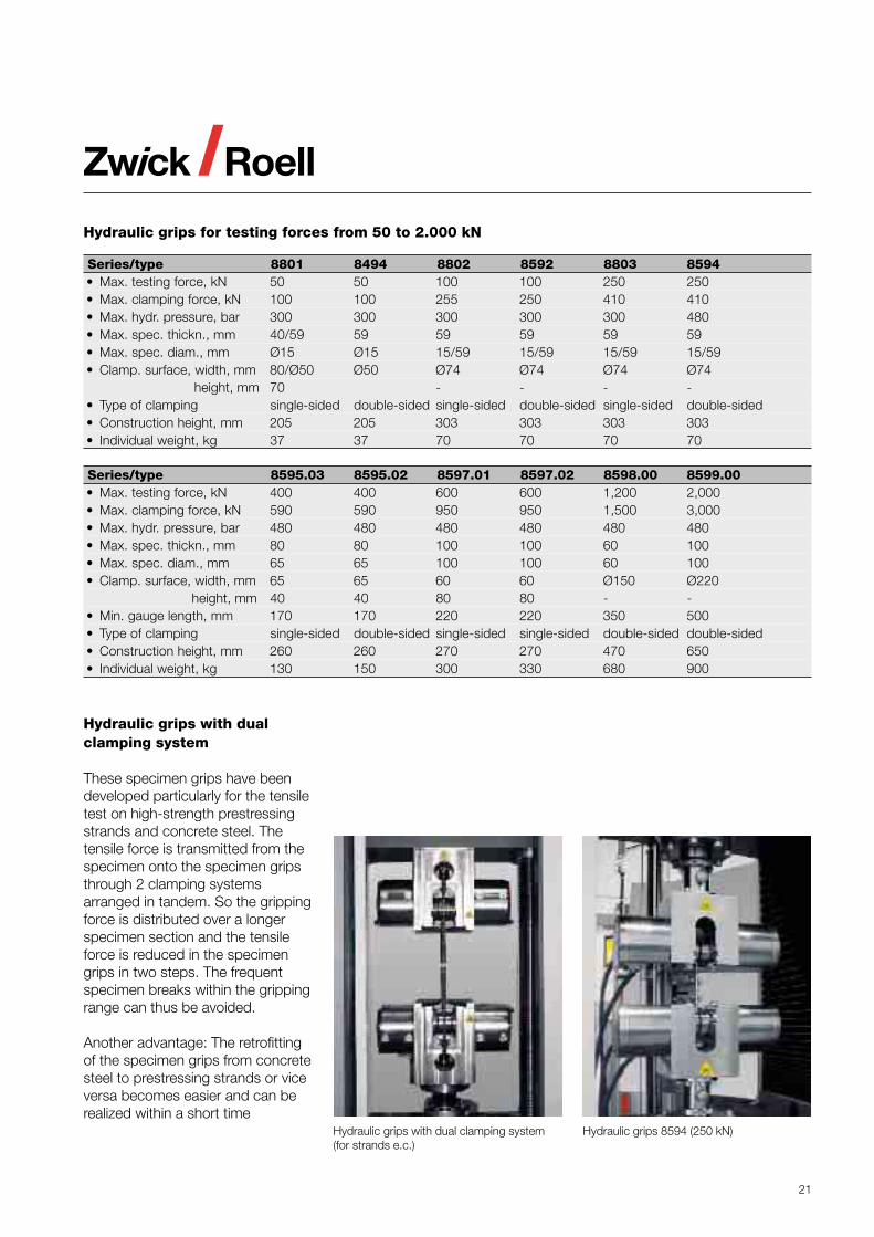
Hydraulic grips for testing forces from 50 to 2.000 kN
Series/type 8801 8494 8802 8592 8803 8594• Max. testing force, kN 50 50 100 100 250 250• Max. clamping force, kN 100 100 255 250 410 410• Max. hydr. pressure, bar 300 300 300 300 300 480• Max. spec. thickn., mm 40/59 59 59 59 59 59• Max. spec. diam., mm Ø15 Ø15 15/59 15/59 15/59 15/59• Clamp. surface, width, mm 80/Ø50 Ø50 Ø74 Ø74 Ø74 Ø74
height, mm 70 - - - -• Type of clamping single-sided double-sided single-sided double-sided single-sided double-sided• Construction height, mm 205 205 303 303 303 303• Individual weight, kg 37 37 70 70 70 70
Series/type 8595.03 8595.02 8597.01 8597.02 8598.00 8599.00• Max. testing force, kN 400 400 600 600 1,200 2,000• Max. clamping force, kN 590 590 950 950 1,500 3,000• Max. hydr. pressure, bar 480 480 480 480 480 480• Max. spec. thickn., mm 80 80 100 100 60 100• Max. spec. diam., mm 65 65 100 100 60 100• Clamp. surface, width, mm 65 65 60 60 Ø150 Ø220
height, mm 40 40 80 80 - -• Min. gauge length, mm 170 170 220 220 350 500• Type of clamping single-sided double-sided single-sided single-sided double-sided double-sided• Construction height, mm 260 260 270 270 470 650• Individual weight, kg 130 150 300 330 680 900
Hydraulic grips 8594 (250 kN)
Hydraulic grips with dualclamping system
These specimen grips have beendeveloped particularly for the tensiletest on high-strength prestressingstrands and concrete steel. Thetensile force is transmitted from thespecimen onto the specimen gripsthrough 2 clamping systemsarranged in tandem. So the grippingforce is distributed over a longerspecimen section and the tensileforce is reduced in the specimengrips in two steps. The frequentspecimen breaks within the grippingrange can thus be avoided.
Another advantage: The retrofittingof the specimen grips from concretesteel to prestressing strands or viceversa becomes easier and can berealized within a short time
Hydraulic grips with dual clamping system(for strands e.c.)
22
Analog clip-on extensometer(for manual operation)
Series/type TC-EXACLEL TC-EXACLEL TC-EXACLEL.001 .002/.003/.004 .005
• Gauge length, mm 25/50 20/10 20/10• Spec. thickn./diam., mm 28 25 40• Measurem. travel, mm 25 +2/-1 ± 2• Travel transducer inductive strain gauge strain gauge
1) DMS = Strain gange
Deformation transducers
Extensometers
For the extension measurement,measurement systems withdifferent gauge lengths, test travelsand resolutions are available:
• Extensometers with contactmeasurement for the manualattachment to the specimen
• Extensometers with contactmeasurement for the manualor automatic attachment ofthe feelers to the specimen
• Extensometers with non-contact,optical measurement withspecimen marks attached onthe specimen
The manually attachable,incremental measurement systemscan already be used with thetesting machines of the standardline.
Motor-driven measurementsystems are controlledautomatically or by means ofa manual control unit. Themacroextensometer is particularlysuitable for the determination ofthe proof stress as well as forthe uniform elongation and forthe strain at break. For the
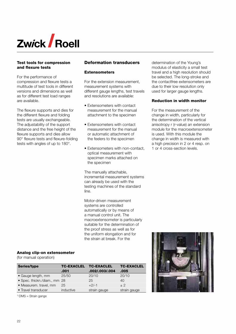
Test tools for compressionand flexure tests
For the performance ofcompression and flexure tests amultitude of test tools in differentversions and dimensions as wellas for different test load rangesare available.
The flexure supports and dies forthe different flexure and foldingtests are usually exchangeable.The adjustability of the supportdistance and the free height of theflexure supports and dies allow90° flexure tests and flexure-foldingtests with angles of up to 180°.
determination of the Young’smodulus of elasticity a small testtravel and a high resolution shouldbe selected. The long-stroke andthe contactfree extensometers aredue to their low resolution onlyused for larger gauge lengths.
Reduction in width monitor
For the measurement of thechange in width, particularly forthe determination of the verticalanisotropy r (r-value) an extensionmodule for the macroextensometeris used. With this module thechange in width is measured witha high precision in 2 or 4 resp. on1 or 4 cross-section levels.
23
Incremental extensometers
Series/type TC-EXMACRO TC-EXLONGS• Description Macro Long stroke• Gauge length, mm 10 bis 100/205 10 bis 1,000• Gauge length adjustmentmanual or automatic manual• Method of attachment manual or automatic automatic• Measurem. travel, mm 80/120/160/75/112,5/150 1,000 – L0
• Resolution, µm 0.12/0.18/0.24/0.3/0.45/0.6 5
Incremental reduction in width monitor
Series/type TC-EXMACWD TC-EXMACWD• Application with Macro and long stroke Macro and long stroke• Specimen width, mm 10 to 15/20 to 25 (2 steps) 10 to 25 (1 step)• No. of measurem. levels 2/4 1/4• Gauge length adjustmentmanual manual• Method of attachment manual or automatic manual or automatic• Measurem. travel, mm 5 >6• Resolution, µm 0.02/0.1 0.02/0.1
Incremental clip-on extensometer(for manual operation)
Series/type TC-EXICLEL.001 TC-EXICLEL.002• Description Incremental Incremental
clip-on extensometer clip-on extensometer• Gauge length, mm 20/25/30 50/55/65/70
(optional 50/80) (optional 80/85/100/105)• Spec. thickn./diam., mm 20x30 or Ø 20 20x30 or Ø 20• Measurem. travel, mm +13.5/-0.2 +40/-0.2• Resolution, µm 0.1 0.1
Series/type TC-EXICLWD TC-EXICLBI TC-EXACLWD.001 .001 .001
• Description Incremental Biaxial Strain gaugereduction in incremental reduction inwidth monitor clip-on extens. width monitor
• Spec. thickness, mm 10 to 20 10 to 20 10/12.5/20/25• No. of measurem. levels 1 1 2• Measurem. travel, mm 1.5 to 11.5 1.5 to 11.5 4• Resolution, µm 0.1 0.1 0.04
Contactfree extensometers
Series/type TC-EXOPTIC TC-EXLASER TC-EXVIDEO• Description Optical Laser Video
extensometer. extensometer. extensometer• Gauge length (L0), mm 10 to 900 10 to 500 5 to 1,000• Measurem. travel, mm 900 minus L0 max. 1,000 % to L0 = 20 mm 50/100/200/500/1,000,
dep. on resolution• Resolution, µm 5 12 0.5/1/2/5/10• Travel transducer incremental laser scanner video, analog
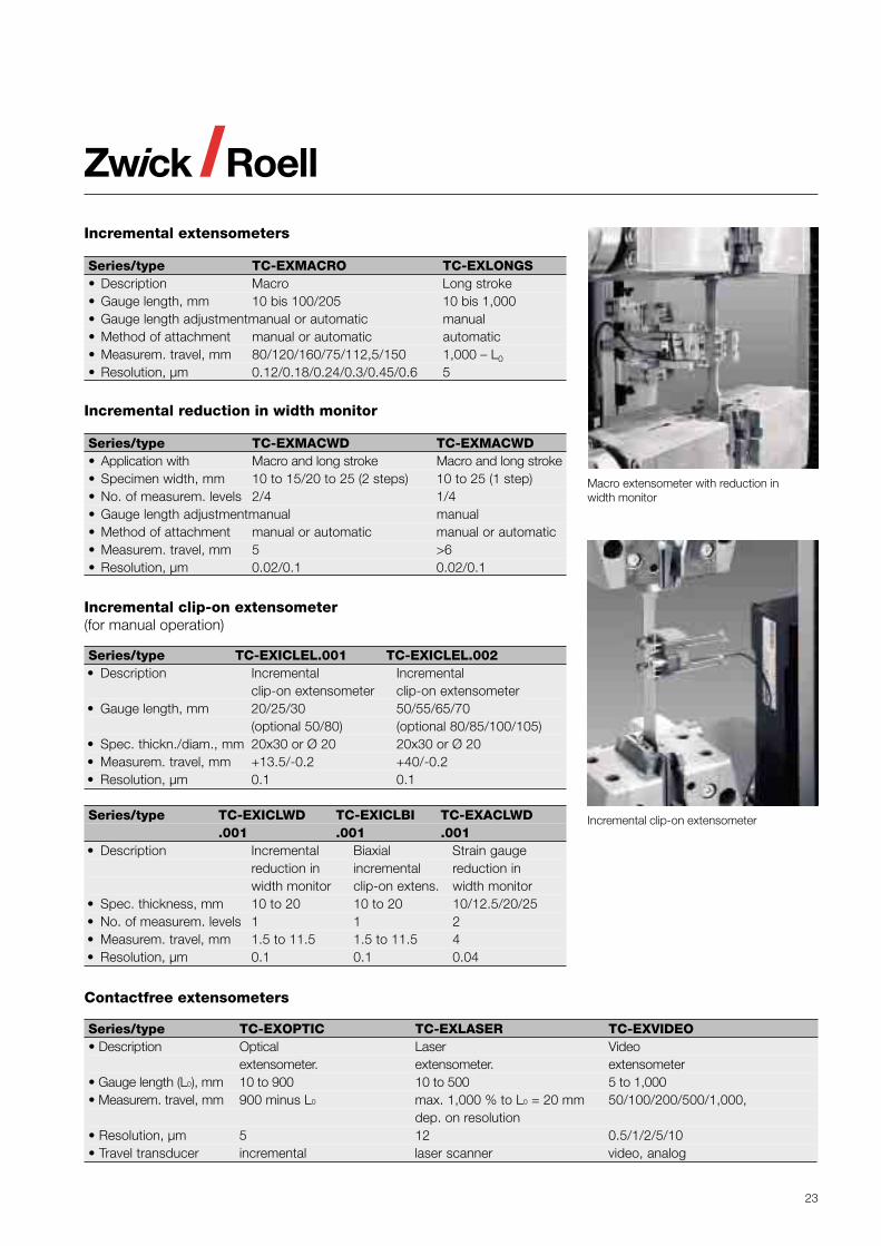
Macro extensometer with reduction inwidth monitor
Incremental clip-on extensometer
24
Specimen feed systems
Application
Automatic specimen feed systemsare used for the efficient testing oflarge series with specimens of thesame type.
Specimen feed systems can besupplied in 5 task-specific designs:• Clip-on system• X-linear system· Polar system• Light portal system• Portal system
Common features:• Integrated system designed
to conform to CE regulations• Data exchange with each Zwick
universal testing machine viaserial interface
• Use with conventional PC’s
Advantages for the user
• Automatic operation• High reproducibility of the test
conditions and test results• High data integrity and
statistical long-termmonitoring
• Manually controlled tests arealso possible
• Simple adaptation andexpansion to specificrequirements through modularsystem
Construction and functionof the individual systems
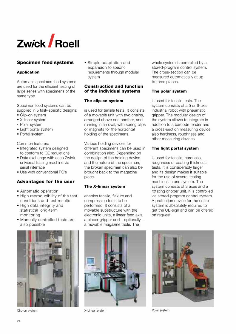
The clip-on system
is used for tensile tests. It consistsof a movable unit with two chains,arranged above one another, andrunning in an oval, with spring clipsor magnets for the horizontalholding of the specimens.
Various holding devices fordifferent specimens can be used incombination also. Depending onthe design of the holding deviceand the nature of the specimen,the broken specimen can also bebrought back to the magazineplace.
The X-linear system
enables tensile, flexure andcompression tests to beperformed. It consists of amovable substructure with theelectronic units, a linear feed axis,a pincer gripper and – optionally –a movable magazine table. The
whole system is controlled by astored-program control system.The cross-section can bemeasured automatically at upto three places.
The polar system
is used for tensile tests. Thesystem consists of a 5 or 6-axisindustrial robot with pneumaticgripper. The modular design ofthe system allows to integrate inaddition to a barcode reader anda cross-section measuring devicealso hardness, roughness andother measuring devices.
The light portal system
is used for tensile, hardness,roughness or coating thicknesstests. It is considerably largerand its design makes it suitablefor the use of several testingmachines in one system. Thesystem consists of 3 axes and arotating gripper unit. It is controlledvia stored-program control system.A protection device for the entiresystem is absolutely required toget the CE-sign and can be offeredon request.
Polar systemX-Linear systemClip-on system
25
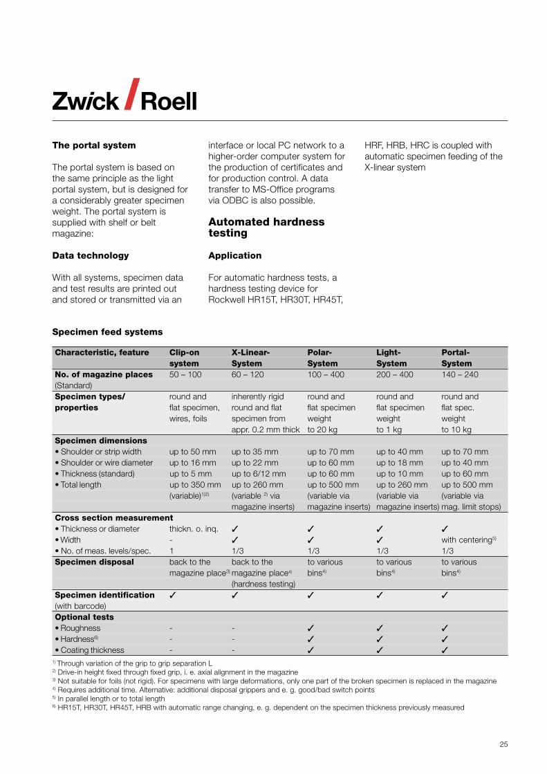
Specimen feed systems
Characteristic, feature Clip-on X-Linear- Polar- Light- Portal-system System System System System
No. of magazine places 50 – 100 60 – 120 100 – 400 200 – 400 140 – 240(Standard)Specimen types/ round and inherently rigid round and round and round andproperties flat specimen, round and flat flat specimen flat specimen flat spec.
wires, foils specimen from weight weight weightappr. 0.2 mm thick to 20 kg to 1 kg to 10 kg
Specimen dimensions• Shoulder or strip width up to 50 mm up to 35 mm up to 70 mm up to 40 mm up to 70 mm• Shoulder or wire diameter up to 16 mm up to 22 mm up to 60 mm up to 18 mm up to 40 mm• Thickness (standard) up to 5 mm up to 6/12 mm up to 60 mm up to 10 mm up to 60 mm• Total length up to 350 mm up to 260 mm up to 500 mm up to 260 mm up to 500 mm
(variable)1)2) (variable 2) via (variable via (variable via (variable viamagazine inserts) magazine inserts) magazine inserts) mag. limit stops)
Cross section measurement• Thickness or diameter thickn. o. inq.• Width - with centering5)
• No. of meas. levels/spec. 1 1/3 1/3 1/3 1/3Specimen disposal back to the back to the to various to various to various
magazine place3) magazine place4) bins4) bins4) bins4)
(hardness testing)Specimen identification(with barcode)Optional tests• Roughness - -• Hardness6) - -• Coating thickness - -
1) Through variation of the grip to grip separation L2) Drive-in height fixed through fixed grip, i. e. axial alignment in the magazine3) Not suitable for foils (not rigid). For specimens with large deformations, only one part of the broken specimen is replaced in the magazine4) Requires additional time. Alternative: additional disposal grippers and e. g. good/bad switch points5) In parallel length or to total length6) HR15T, HR30T, HR45T, HRB with automatic range changing, e. g. dependent on the specimen thickness previously measured
The portal system
The portal system is based onthe same principle as the lightportal system, but is designed fora considerably greater specimenweight. The portal system issupplied with shelf or beltmagazine:
Data technology
With all systems, specimen dataand test results are printed outand stored or transmitted via an
interface or local PC network to ahigher-order computer system forthe production of certificates andfor production control. A datatransfer to MS-Office programsvia ODBC is also possible.
Automated hardnesstesting
Application
For automatic hardness tests, ahardness testing device forRockwell HR15T, HR30T, HR45T,
HRF, HRB, HRC is coupled withautomatic specimen feeding of theX-linear system
26
Application
Mechanical fracturing tests for therating of safety risks describe thepropagation of an already existingcrack by recognizing faults in thematerial.
Standard testing machines,equipped with the correspondingaccessories (specimen grips, crackopening transducers, software) areused for the determination ofdifferent characteristic data offracture mechanics.
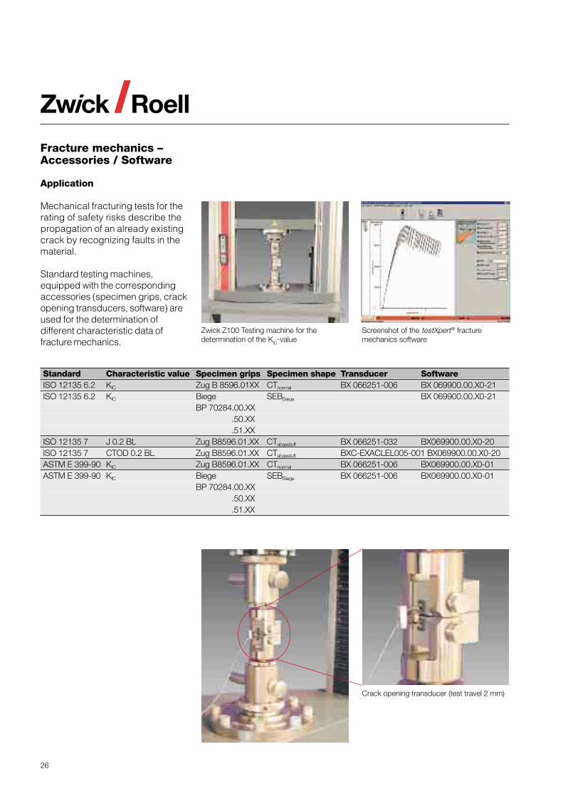
Fracture mechanics –Accessories / Software
Standard Characteristic value Specimen grips Specimen shape Transducer SoftwareISO 12135 6.2 KIC Zug B 8596.01XX CTnormal BX 066251-006 BX 069900.00.X0-21ISO 12135 6.2 KIC Biege SEBBiege BX 069900.00.X0-21
BP 70284.00.XX .50.XX .51.XX
ISO 12135 7 J 0.2 BL Zug B8596.01.XX CTabgestuft BX 066251-032 BX069900.00.X0-20ISO 12135 7 CTOD 0.2 BL Zug B8596.01.XX CTabgestuft BXC-EXACLEL005-001 BX069900.00.X0-20ASTM E 399-90 KIC Zug B8596.01.XX CTnormal BX 066251-006 BX069900.00.X0-01ASTM E 399-90 KIC Biege SEBBiege BX 066251-006 BX069900.00.X0-01
BP 70284.00.XX .50.XX .51.XX
Zwick Z100 Testing machine for thedetermination of the KIC-value
Crack opening transducer (test travel 2 mm)
Screenshot of the testXpert® fracturemechanics software
27
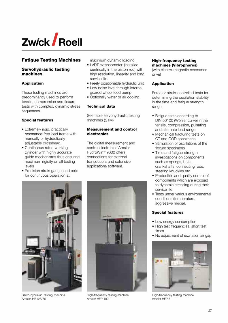
Fatigue Testing Machines
Servohydraulic testingmachines
Application
These testing machines arepredominantly used to performtensile, compression and flexuretests with complex, dynamic stresssequences.
Special features
• Extremely rigid, practicallyresonance-free load frame withmanually or hydraulicallyadjustable crosshead.
• Continuous rated workingcylinder with highly accurateguide mechanisms thus ensuringmaximum rigidity on all testinglevels
• Precision strain gauge load cellsfor continuous operation at
maximum dynamic loading• LVDT-extensometer (installed
centrically in the piston rod) withhigh resolution, linearity and longservice life.
• Freely positionable hydraulic unit• Low noise level through internal
geared wheel feed pump• Optionally water or air cooling
Technical data
See table servohydraulic testingmachines (STM)
Measurement and controlelectronics
The digital measurement andcontrol electronics AmslerHydroWin® 9600 offersconnections for externaltransducers and extensiveapplications software.
High-frequency testing machineAmsler HFP 400
High-frequency testing machineAmsler HFP 5
Servo-hydraulic testing machineAmsler HB126/80
High-frequency testingmachines (Vibrophores)(with electro-magnetic resonancedrive)
Application
Force or strain-controlled tests fordetermining the oscillation stabilityin the time and fatigue strengthrange.
• Fatigue tests according toDIN 50100 (Wöhler curve) in thetensile, compression, pulsatingand alternate load range
• Mechanical fracturing tests onCT and COD specimens
• Stimulation of oscillations of theflexure specimens
• Time and fatigue-strengthinvestigations on componentssuch as springs, bolts,crankshafts, connecting rods,steering knuckles etc.
• Production and quality control ofcomponents which are exposedto dynamic stressing during theirservice life.
• Tests under various environmentalconditions (temperature,aggressive media).
Special features
• Low energy consumption• High test frequencies, short test
times• No adjustment of excitation air gap
28
High-Frequency testing machines (HFP)
Series/type Amsler HFP 1 - 5 Amsler HFP 20 - 550• Construction type table top floor standing• Load frame nominal force, kN 1 - 5 20 - 550• Max. force amplitude, kN 2.5 275• Max. elast. spec. deform., mm ± 3 ± 2• Frequency range, Hz 35 - 300 35 - 300• Frequency levels 5 16/5• Working area width, mm 350 530/600• Max. power consum., kVA 2 5
Rotary bending testing machines (UBM)
Series/type AmslerUBM 200 Amsler UBM 2000 • Max. bending moment, Nm 200 2,000 • Load reversal frequency, min-1 50 - 5000 600 – 3000 • Max. specimen diameter, mm 25 50 • Max. power consum., kVA 1.6 5.5
Servo-hydraulic testing machines (STM)Standard design1)
Series/type2) HC HB HA• Construction type table top floor stand. floor stand.• Load frame nominal force, kN 5 - 25 50 - 1,000 50 - 500• Test stroke, mm 100 100/250/400 100/250• Specimen length, mm 100 - 700 100 - 1,100 250 - 1,500• Hydraulic unit
* System pressure, bar 210/280 210/280 210/280* Flow, l/min 4 – 23 9 – 600 9 - 600
• Max. power consum., kVA 2.2 – 11 2.2 – 74 2.2 - 741) Load frames and actuators for higher nominal forces on request2) In the HC and HB serie the actuators are situated in the upper crosshead, in the HA serie
in the lower crosshead
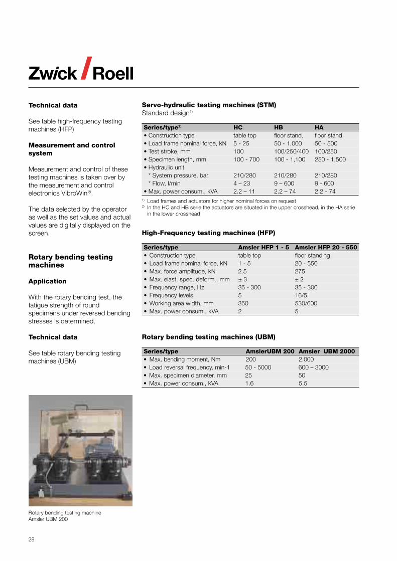
Rotary bending testingmachines
Application
With the rotary bending test, thefatigue strength of roundspecimens under reversed bendingstresses is determined.
Technical data
See table rotary bending testingmachines (UBM)
Rotary bending testing machineAmsler UBM 200
Technical data
See table high-frequency testingmachines (HFP)
Measurement and controlsystem
Measurement and control of thesetesting machines is taken over bythe measurement and controlelectronics VibroWin®.
The data selected by the operatoras well as the set values and actualvalues are digitally displayed on thescreen.
29
Measurement and controlelectronics
The control electronics SpeedWin®
with the user software testXpert®
allows an extensive evaluation oftest results as well as the creationof test reports and dataadministration.
Technical data
See table high-speed testingmachines (HTM)
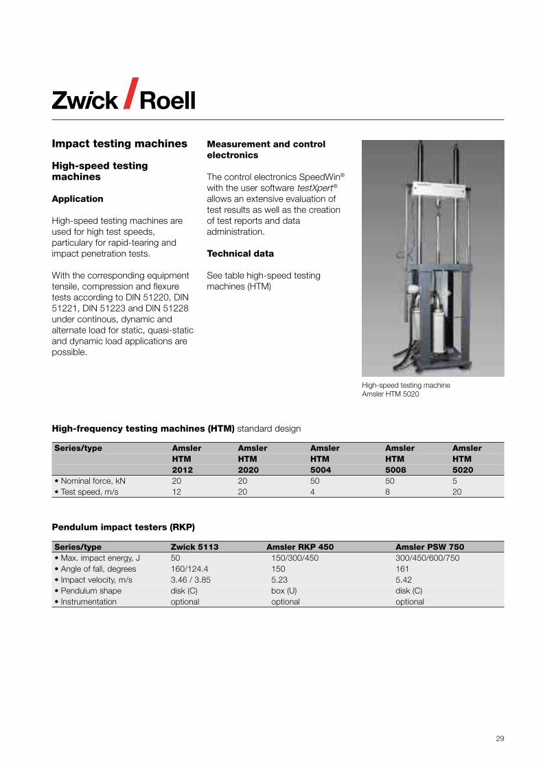
Impact testing machines
High-speed testingmachines
Application
High-speed testing machines areused for high test speeds,particulary for rapid-tearing andimpact penetration tests.
With the corresponding equipmenttensile, compression and flexuretests according to DIN 51220, DIN51221, DIN 51223 and DIN 51228under continous, dynamic andalternate load for static, quasi-staticand dynamic load applications arepossible.
Pendulum impact testers (RKP)
Series/type Zwick 5113 Amsler RKP 450 Amsler PSW 750• Max. impact energy, J 50 150/300/450 300/450/600/750• Angle of fall, degrees 160/124.4 150 161• Impact velocity, m/s 3.46 / 3.85 5.23 5.42• Pendulum shape disk (C) box (U) disk (C)• Instrumentation optional optional optional
High-frequency testing machines (HTM) standard design
Series/type Amsler Amsler Amsler Amsler AmslerHTM HTM HTM HTM HTM2012 2020 5004 5008 5020
• Nominal force, kN 20 20 50 50 5• Test speed, m/s 12 20 4 8 20
High-speed testing machineAmsler HTM 5020
30
Pendulum impact tester Amsler RKP 450
Pendulum impact tester Zwick 5113
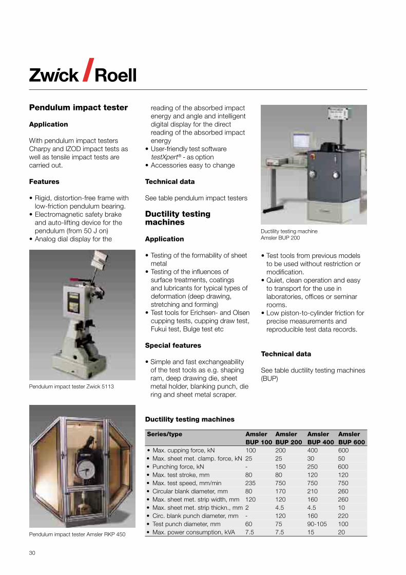
Pendulum impact tester
Application
With pendulum impact testersCharpy and IZOD impact tests aswell as tensile impact tests arecarried out.
Features
• Rigid, distortion-free frame withlow-friction pendulum bearing.
• Electromagnetic safety brakeand auto-lifting device for thependulum (from 50 J on)
• Analog dial display for the
reading of the absorbed impactenergy and angle and intelligentdigital display for the directreading of the absorbed impactenergy
• User-friendly test softwaretestXpert® - as option
• Accessories easy to change
Technical data
See table pendulum impact testers
Ductility testingmachines
Application
• Testing of the formability of sheetmetal
• Testing of the influences ofsurface treatments, coatingsand lubricants for typical types ofdeformation (deep drawing,stretching and forming)
• Test tools for Erichsen- and Olsencupping tests, cupping draw test,Fukui test, Bulge test etc
Special features
• Simple and fast exchangeabilityof the test tools as e.g. shapingram, deep drawing die, sheetmetal holder, blanking punch, diering and sheet metal scraper.
• Test tools from previous modelsto be used without restriction ormodification.
• Quiet, clean operation and easyto transport for the use inlaboratories, offices or seminarrooms.
• Low piston-to-cylinder friction forprecise measurements andreproducible test data records.
Technical data
See table ductility testing machines(BUP)
Ductility testing machines
Series/type Amsler Amsler Amsler AmslerBUP 100 BUP 200 BUP 400 BUP 600
• Max. cupping force, kN 100 200 400 600• Max. sheet met. clamp. force, kN 25 25 30 50• Punching force, kN - 150 250 600• Max. test stroke, mm 80 80 120 120• Max. test speed, mm/min 235 750 750 750• Circular blank diameter, mm 80 170 210 260• Max. sheet met. strip width, mm 120 120 160 260• Max. sheet met. strip thickn., mm 2 4.5 4.5 10• Circ. blank punch diameter, mm - 120 160 220• Test punch diameter, mm 60 75 90-105 100• Max. power consumption, kVA 7.5 7.5 15 20
Ductility testing machineAmsler BUP 200
31
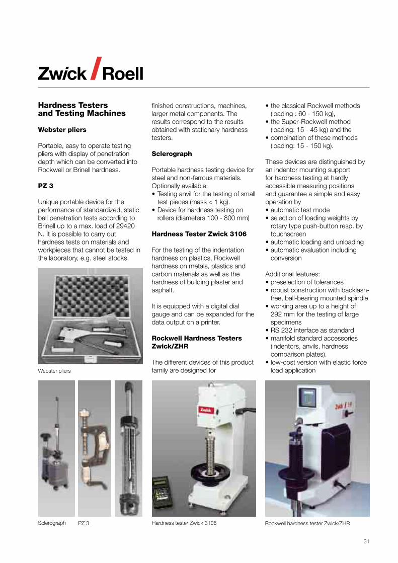
Webster pliers
Hardness Testersand Testing Machines
Webster pliers
Portable, easy to operate testingpliers with display of penetrationdepth which can be converted intoRockwell or Brinell hardness.
PZ 3
Unique portable device for theperformance of standardized, staticball penetration tests according toBrinell up to a max. load of 29420N. It is possible to carry outhardness tests on materials andworkpieces that cannot be tested inthe laboratory, e.g. steel stocks,
finished constructions, machines,larger metal components. Theresults correspond to the resultsobtained with stationary hardnesstesters.
Sclerograph
Portable hardness testing device forsteel and non-ferrous materials.Optionally available:• Testing anvil for the testing of small
test pieces (mass < 1 kg).• Device for hardness testing on
rollers (diameters 100 - 800 mm)
Hardness Tester Zwick 3106
For the testing of the indentationhardness on plastics, Rockwellhardness on metals, plastics andcarbon materials as well as thehardness of building plaster andasphalt.
It is equipped with a digital dialgauge and can be expanded for thedata output on a printer.
Rockwell Hardness TestersZwick/ZHR
The different devices of this productfamily are designed for
• the classical Rockwell methods(loading : 60 - 150 kg),
• the Super-Rockwell method(loading: 15 - 45 kg) and the
• combination of these methods(loading: 15 - 150 kg).
These devices are distinguished byan indentor mounting supportfor hardness testing at hardlyaccessible measuring positionsand guarantee a simple and easyoperation by• automatic test mode• selection of loading weights by
rotary type push-button resp. bytouchscreen
• automatic loading and unloading• automatic evaluation including
conversion
Additional features:• preselection of tolerances• robust construction with backlash-
free, ball-bearing mounted spindle• working area up to a height of
292 mm for the testing of largespecimens
• RS 232 interface as standard• manifold standard accessories
(indentors, anvils, hardnesscomparison plates).
• low-cost version with elastic forceload application
Sclerograph Hardness tester Zwick 3106 Rockwell hardness tester Zwick/ZHRPZ 3
32
• The PC version (3212003) workswith the user software testXpert®
which is easy to use and whichcan be flexibly adapted tochanging test conditions.Theindentation is measured at themonitor and is evaluatedautomatically. A Master testprogram for Vickers, Knoop andBrinell hardness tests is availablefor series measurements whichcan be extended for hardnessgradient tests and automaticindentation measurement. Inaddition to manually movable ormotorized compound tables, avariety of further accessories ase.g. clamping devices areavailable.
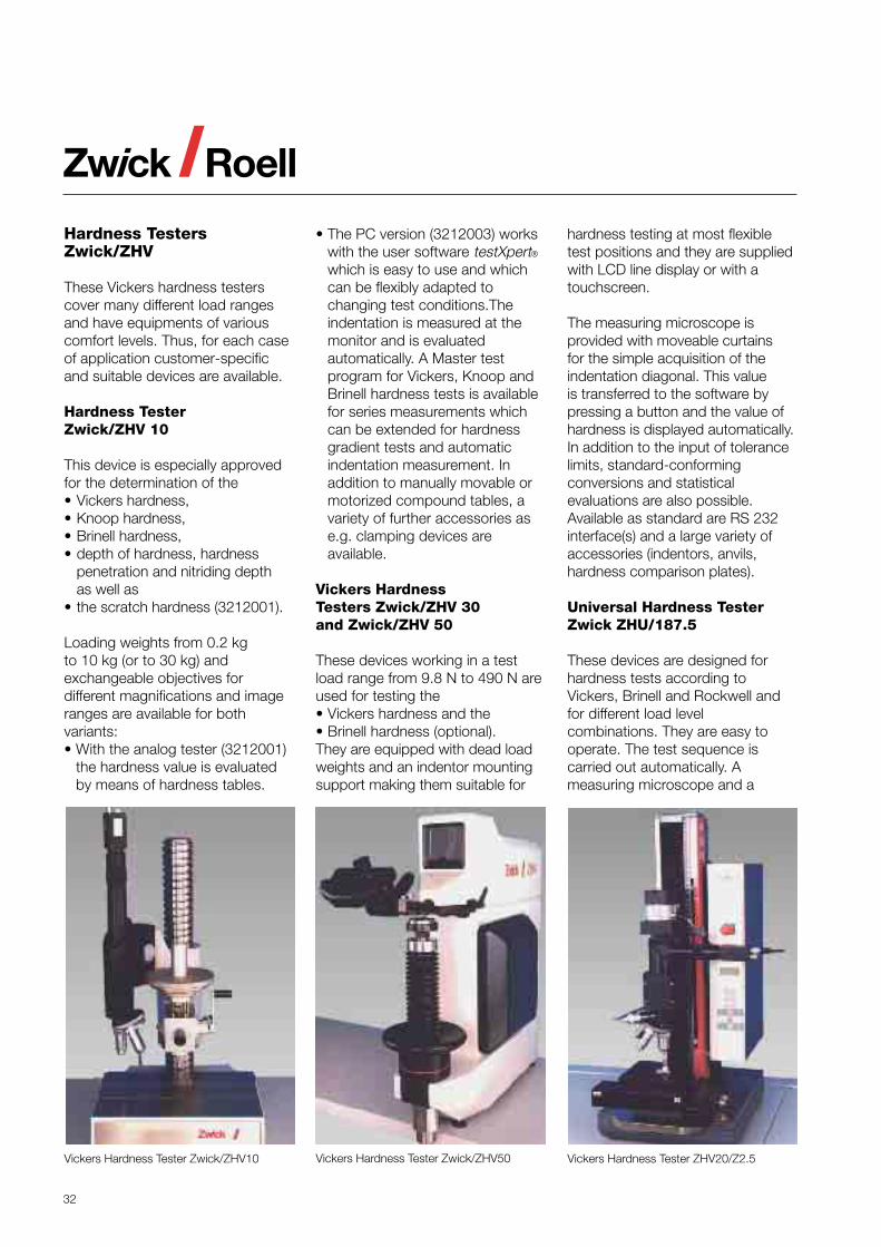
Vickers HardnessTesters Zwick/ZHV 30and Zwick/ZHV 50
These devices working in a testload range from 9.8 N to 490 N areused for testing the• Vickers hardness and the• Brinell hardness (optional).They are equipped with dead loadweights and an indentor mountingsupport making them suitable for
Vickers Hardness Tester ZHV20/Z2.5Vickers Hardness Tester Zwick/ZHV50Vickers Hardness Tester Zwick/ZHV10
Hardness TestersZwick/ZHV
These Vickers hardness testerscover many different load rangesand have equipments of variouscomfort levels. Thus, for each caseof application customer-specificand suitable devices are available.
Hardness TesterZwick/ZHV 10
This device is especially approvedfor the determination of the• Vickers hardness,• Knoop hardness,• Brinell hardness,• depth of hardness, hardness
penetration and nitriding depthas well as
• the scratch hardness (3212001).
Loading weights from 0.2 kgto 10 kg (or to 30 kg) andexchangeable objectives fordifferent magnifications and imageranges are available for bothvariants:• With the analog tester (3212001)
the hardness value is evaluatedby means of hardness tables.
hardness testing at most flexibletest positions and they are suppliedwith LCD line display or with atouchscreen.
The measuring microscope isprovided with moveable curtainsfor the simple acquisition of theindentation diagonal. This valueis transferred to the software bypressing a button and the value ofhardness is displayed automatically.In addition to the input of tolerancelimits, standard-conformingconversions and statisticalevaluations are also possible.Available as standard are RS 232interface(s) and a large variety ofaccessories (indentors, anvils,hardness comparison plates).
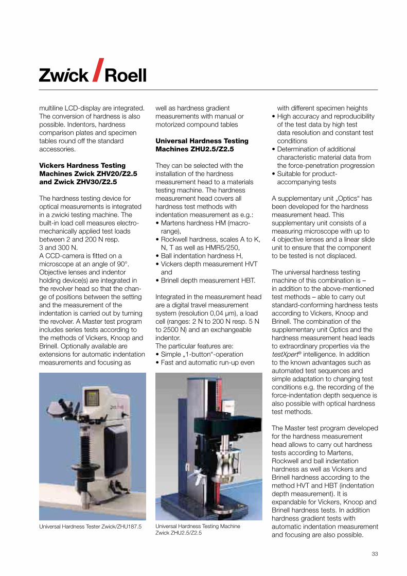
Universal Hardness TesterZwick ZHU/187.5
These devices are designed forhardness tests according toVickers, Brinell and Rockwell andfor different load levelcombinations. They are easy tooperate. The test sequence iscarried out automatically. Ameasuring microscope and a
33
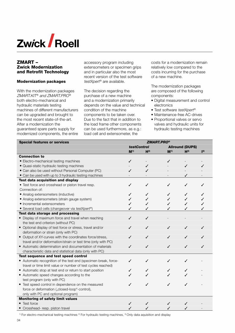
Universal Hardness Tester Zwick/ZHU187.5 Universal Hardness Testing MachineZwick ZHU2.5/Z2.5
multiline LCD-display are integrated.The conversion of hardness is alsopossible. Indentors, hardnesscomparison plates and specimentables round off the standardaccessories.
Vickers Hardness TestingMachines Zwick ZHV20/Z2.5and Zwick ZHV30/Z2.5
The hardness testing device foroptical measurements is integratedin a zwicki testing machine. Thebuilt-in load cell measures electro-mechanically applied test loadsbetween 2 and 200 N resp.3 and 300 N.A CCD-camera is fitted on amicroscope at an angle of 90°.Objective lenses and indentorholding device(s) are integrated inthe revolver head so that the chan-ge of positions between the settingand the measurement of theindentation is carried out by turningthe revolver. A Master test programincludes series tests according tothe methods of Vickers, Knoop andBrinell. Optionally available areextensions for automatic indentationmeasurements and focusing as
well as hardness gradientmeasurements with manual ormotorized compound tables
Universal Hardness TestingMachines ZHU2.5/Z2.5
They can be selected with theinstallation of the hardnessmeasurement head to a materialstesting machine. The hardnessmeasurement head covers allhardness test methods withindentation measurement as e.g.:• Martens hardness HM (macro-
range),• Rockwell hardness, scales A to K,
N, T as well as HMR5/250,• Ball indentation hardness H,• Vickers depth measurement HVT
and• Brinell depth measurement HBT.
Integrated in the measurement headare a digital travel measurementsystem (resolution 0,04 µm), a loadcell (ranges: 2 N to 200 N resp. 5 Nto 2500 N) and an exchangeableindentor.The particular features are:• Simple „1-button“-operation• Fast and automatic run-up even
with different specimen heights• High accuracy and reproducibility
of the test data by high testdata resolution and constant testconditions
• Determination of additionalcharacteristic material data fromthe force-penetration progression
• Suitable for product-accompanying tests
A supplementary unit „Optics“ hasbeen developed for the hardnessmeasurement head. Thissupplementary unit consists of ameasuring microscope with up to4 objective lenses and a linear slideunit to ensure that the componentto be tested is not displaced.
The universal hardness testingmachine of this combination is –in addition to the above-mentionedtest methods – able to carry outstandard-conforming hardness testsaccording to Vickers, Knoop andBrinell. The combination of thesupplementary unit Optics and thehardness measurement head leadsto extraordinary properties via thetestXpert® intelligence. In additionto the known advantages such asautomated test sequences andsimple adaptation to changing testconditions e.g. the recording of theforce-indentation depth sequence isalso possible with optical hardnesstest methods.
The Master test program developedfor the hardness measurementhead allows to carry out hardnesstests according to Martens,Rockwell and ball indentationhardness as well as Vickers andBrinell hardness according to themethod HVT and HBT (indentationdepth measurement). It isexpandable for Vickers, Knoop andBrinell hardness tests. In additionhardness gradient tests withautomatic indentation measurementand focusing are also possible.
34
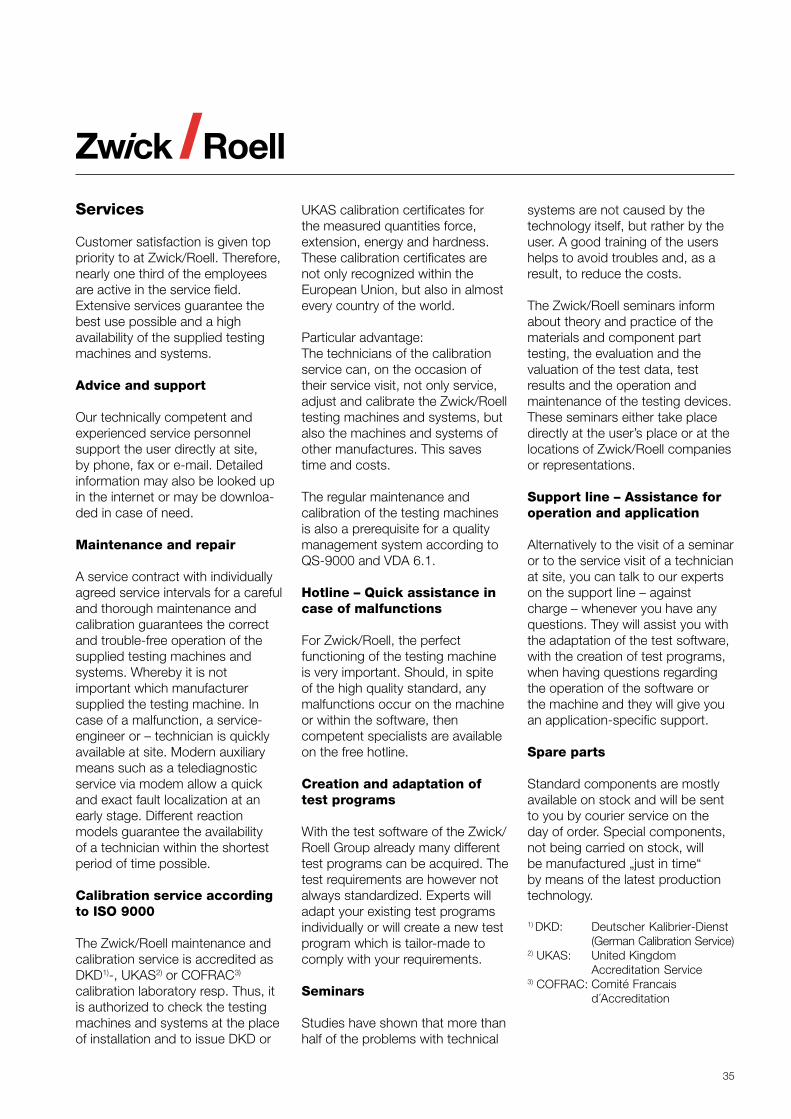
Special features or services ZMART.PRO®
testControl Allround (DUPS)M1) H2) M1) H2) I3)
Connection to• Electro-mechanical testing machines - - -• Quasi-static hydraulic testing machines - -• Can also be used without Personal Computer (PC) - - -• Can be used with up to 3 hydraulic testing machines - - - -Test data acquisition and display• Test force and crosshead or piston travel resp.Connection of:• Analog extensometers (inductive)• Analog extensometers (strain gauge system)• Incremental extensometers• Several load cells (changeover via testXpert®)Test data storage and processing• Display of maximum force and travel when reaching - - -
the test end criterion (without PC)• Optional display of test force or stress, travel and/or
deformation or strain (only with PC)• Output of XY-curves with the coordinates force/stress,
travel and/or deformation/strain or test time (only with PC)• Automatic determination and documentation of materials
characteristic data and statistical data (only with PC)Test sequence and test speed control• Automatic recognition of the test end (specimen break, force- -
travel or time limit value or number of test cycles reached)• Automatic stop at test end or return to start position -• Automatic speed changes according to the -
test program (only with PC)• Test speed control in dependence on the measured -
force or deformation („closed-loop“-control),only with PC and optional program)
Monitoring of safety limit values• Test force -• Crosshead- resp. piston travel -
1) For electro-mechanical testing machines 2) For hydraulic testing machines, 3) Only data aquisition and display
ZMART –Zwick Modernizationand Retrofit Technology
Modernization packages
With the modernization packagesZMART.KIT® and ZMART.PRO®
both electro-mechanical andhydraulic materials testingmachines of different manufacturerscan be upgraded and brought tothe most recent state-of-the-art.After a modernization theguaranteed spare parts supply formodernized components, the entire
accessory program includingextensometers or specimen gripsand in particular also the mostrecent version of the test softwaretestXpert® are available.
The decision regarding thepurchase of a new machineand a modernization primarilydepends on the value and technicalcondition of the machinecomponents to be taken over.Due to the fact that in addition tothe load frame other componentscan be used furthermore, as e.g.:load cell and extensometer, the
costs for a modernization remainrelatively low compared to thecosts incurring for the purchaseof a new machine.
The modernization packagesare composed of the followingcomponents:• Digital measurement and control
electronics• Test software testXpert®
• Maintenance-free AC-drives• Proportional valves or servo
valves and hydraulic units forhydraulic testing machines
35
Services
Customer satisfaction is given toppriority to at Zwick/Roell. Therefore,nearly one third of the employeesare active in the service field.Extensive services guarantee thebest use possible and a highavailability of the supplied testingmachines and systems.
Advice and support
Our technically competent andexperienced service personnelsupport the user directly at site,by phone, fax or e-mail. Detailedinformation may also be looked upin the internet or may be downloa-ded in case of need.
Maintenance and repair
A service contract with individuallyagreed service intervals for a carefuland thorough maintenance andcalibration guarantees the correctand trouble-free operation of thesupplied testing machines andsystems. Whereby it is notimportant which manufacturersupplied the testing machine. Incase of a malfunction, a service-engineer or – technician is quicklyavailable at site. Modern auxiliarymeans such as a telediagnosticservice via modem allow a quickand exact fault localization at anearly stage. Different reactionmodels guarantee the availabilityof a technician within the shortestperiod of time possible.
Calibration service accordingto ISO 9000
The Zwick/Roell maintenance andcalibration service is accredited asDKD1)-, UKAS2) or COFRAC3)
calibration laboratory resp. Thus, itis authorized to check the testingmachines and systems at the placeof installation and to issue DKD or
UKAS calibration certificates forthe measured quantities force,extension, energy and hardness.These calibration certificates arenot only recognized within theEuropean Union, but also in almostevery country of the world.
Particular advantage:The technicians of the calibrationservice can, on the occasion oftheir service visit, not only service,adjust and calibrate the Zwick/Roelltesting machines and systems, butalso the machines and systems ofother manufactures. This savestime and costs.
The regular maintenance andcalibration of the testing machinesis also a prerequisite for a qualitymanagement system according toQS-9000 and VDA 6.1.
Hotline – Quick assistance incase of malfunctions
For Zwick/Roell, the perfectfunctioning of the testing machineis very important. Should, in spiteof the high quality standard, anymalfunctions occur on the machineor within the software, thencompetent specialists are availableon the free hotline.
Creation and adaptation oftest programs
With the test software of the Zwick/Roell Group already many differenttest programs can be acquired. Thetest requirements are however notalways standardized. Experts willadapt your existing test programsindividually or will create a new testprogram which is tailor-made tocomply with your requirements.
Seminars
Studies have shown that more thanhalf of the problems with technical
systems are not caused by thetechnology itself, but rather by theuser. A good training of the usershelps to avoid troubles and, as aresult, to reduce the costs.
The Zwick/Roell seminars informabout theory and practice of thematerials and component parttesting, the evaluation and thevaluation of the test data, testresults and the operation andmaintenance of the testing devices.These seminars either take placedirectly at the user’s place or at thelocations of Zwick/Roell companiesor representations.
Support line – Assistance foroperation and application
Alternatively to the visit of a seminaror to the service visit of a technicianat site, you can talk to our expertson the support line – againstcharge – whenever you have anyquestions. They will assist you withthe adaptation of the test software,with the creation of test programs,when having questions regardingthe operation of the software orthe machine and they will give youan application-specific support.
Spare parts
Standard components are mostlyavailable on stock and will be sentto you by courier service on theday of order. Special components,not being carried on stock, willbe manufactured „just in time“by means of the latest productiontechnology.
1) DKD: Deutscher Kalibrier-Dienst(German Calibration Service)
2) UKAS: United KingdomAccreditation Service
3) COFRAC: Comité Francaisd´Accreditation

36