testing of exhaust ventilation - vent-tech · maintain local exhaust ventilation ... inlets such as...
TRANSCRIPT

Maintenance, examination and testing of local
exhaust ventilation

Maintenance, examination and testing of local
exhaust ventilation

Maintenance, examination and testing of local exhaust ventilation
© Crown copyright 1998
First published 1990 Second edition 1998 Reprinted 2000, 2001, 2002. 2004
ISBN 0 7176 1485 9
All rights reserved. No part of this publication may be reproduced, stored in a retrieval system, or transmitted in any form or by any means (electronic, mechanical, photocopying, recording or otherwise) without the prior written permission of the copyright owner.
Applications for reproduction should be made in writing to: Licensing Division, Her Majesty's Stationery Office, St Clements House, 2-16 Colegate, Norwich NR3 1BQ or by e-mail to [email protected]
This guidance is issued by the Health and Safety Executive. Following the guidance is not compulsory and you are free to take other action. But if you do follow the guidance you will normally be doing enough to comply with the law. Health and safety inspectors seek to secure compliance with the law and may refer to this guidance as illustrating good practice.
Introduction 1What is a local exhaust ventilation system? 1
The legal requirements 3Use of LEV 3Maintenance, examination and testing of LEV 3Other regulations 4
Selection of personnel and their protection 5Selection of suitable personnel 5Protection of personnel 6
Procedure 7Initial appraisal 7Maintenance 8Thorough examination and testing 11Making a judgement 14
Instruments and techniques 15Air monitoring 15Measurement of LEV plant performance 15Flow visualisation devices and tracers 16Maintenance and calibration of instruments 16
Records, reporting and action 17
Appendices1 Information required of an LEV system 192 Measurement of plant performance 233 Measurement of static and velocity pressure 254 Air velocity measurement 295 Use of flow visualisation techniques 316 Equations used in LEV testing 33
References 35

r
Maintenance, examination and testing of local exhaust ventilation

v,'
CA
D
sac
Lc.
t-.
c..
t+1
Maintenance, examination and testing of local exhaust ventilation
Introduction I This guidance provides advice to employers and others who operate, service and maintain local exhaust ventilation (LEV) systems. The aim is to ensure that LEV systems which are intended to control substances hazardous to health, including biological agents, continue to operate as originally intended. A system should be able to effectively capture released hazardous airborne substances, remove them from the workplace and safely dispose of them. This then protects the health of people indoors and outside.
2 For this purpose legislation requires that LEV systems should be well maintained, thoroughly examined and tested at regular intervals. You should always remember that effective maintenance is essential for the continuing provision of an effective and efficient system.
What is a local exhaust ventilation system?
3 It is a system that:
uses extract ventilation to prevent or reduce the level of airborne hazardous substances from being breathed by people in the workplace;
draws pollutants away from a process or operation that is likely to release a
hazardous substance into the workroom air; and
consists of an inlet such as a hood, slot, booth or cabinet placed around or close to the point of release of the substance. This device is connected via ducting to the inlet of a fan or air mover. The extracted air is usually discharged to the atmosphere or returned elsewhere in the workplace, having first been cleaned to make it safe for release (see HSG37 An introduction to local exhaust ventilation').
Components of an LEV system, see Figure 1
Inlets such as a booth, hood, slot, canopy, cabinet, or enclosure.
Ducting which may contain bends, junctions, changes of section and dampers; it
may be circular or rectangular in cross-section and be rigid or flexible.
Fan or occasionally some other type of air mover such as a compressed air venturi.
Air cleaner (where necessary) such as a dust filter, wet scrubber, or solvent recovery device.
Discharge to the atmosphere or a room via a stack, diffuser, grille or just an open duct.
Introduction

r17
Maintenance, examination and testing of local exhaust ventilation
Figure 1 Components of a local exhaust ventilation system
4 For the purpose of deciding the frequency of thorough examination and testing, it may be necessary in some situations to decide if an item of plant is LEV. For example:
Treat parts of equipment such as the machine casing and guards as LEV if they are directly ventilated and if one of their functions is to control emissions.
Regard make-up air systems that replace exhausted air as LEV if they are an integral part of an exhaust system, eg where ventilated booths and cabinets need make-up air to work properly.
Flues from furnaces, ovens etc are LEV where the draught created by the flue is necessary to control the release of hazardous substances.
Vacuum cleaners are not LEV when used for cleaning surfaces. They are LEV if connected to a portable machine or tool.
Introduction

CTS
.w..
Maintenance, examination and testing of local exhaust ventilation
The legal requirements Use of LEV
5 Regulation 7 of the Control of Substances Hazardous to Health (COSHH) Regulations 2002, requires that the exposure of employees to substances hazardous to health be either prevented or, where that is not reasonably practicable, adequately controlled (see HSE guidance publication EH402). Schedule 3 of the regulation deals with the special provisions relating to biological agents. The regulation is supported by the COSHH Approved Code of Practice3 which lists ways in which control can be achieved and makes specific mention of enclosure, partial enclosure with LEV, LEV and sufficient general ventilation.
Maintenance, examination and testing of LEV
6 Regulation 9 of COSHH requires that any control measure taken to comply with regulation 7 must be maintained in an efficient state, in efficient working order, good repair and in clean condition. LEV systems should be examined and tested at least once every 14 months.
7 However, there are minimum frequencies for LEV systems used in conjunction with processes listed in Schedule 4 to regulation 9(2) (a) as shown in Table 1.
Table 1 Frequency of thorough examination and testing of LEV plant used in certain processes
Process Minimum frequency
Processes in which blasting is carried out in or incidental to the cleaning of metal castings in connection with their manufacture. 1 month
Jute cloth manufacture. 1 month
Processes other than wet processes, in which metal articles (other than of gold, platinum or iridium) are ground, abraded or polished using mechanical power, in any room for more than 12 hours per week. 6 months
Processes giving off dust or fume in which non-ferrous metal castings are produced. 6 months
8 Regulation 9 also specifies that records shall be kept of the results of the tests including details of any repairs carried out as a result of the examinations and tests. These records have to be kept for at least five years.
The legal requirements

.O.
Maintenance, examination and testing of local exhaust ventilation
1) There is a duty (regulation 8) on the employee to use the LEV provided and to report any defects observed.
10 Both COSHH and the Management of Health and Safety at Work Regulations 1999° require that those who carry out duties under these Regulations should be competent to do so.
Other regulations
1 1 The Management of Health and Safety at Work Regulations 1999 require an employer to make appropriate arrangements for the effective planning, organisation, control, monitoring and review of the preventative and protective measures, which includes LEV systems. The Control of Asbestos at Work Regulations 19871 and the Control of Lead at Work Regulations 19981 also impose specific requirements for the provision of and maintenance, examination and testing of LEV. Furthermore, the Workplace (Health, Safety and Welfare) Regulations 1992 require the maintenance of general ventilation systems (not covered in this document).
The legal requirements

4..
Maintenance, examination and testing of local exhaust ventilation
Selection of personnel and their protection Selection of suitable personnel
12 The legal duty to provide and maintain effective control measures, including LEV, rests with the employer. But the maintenance, examination and testing can be carried out by an employee or by an outside contractor. However, it is preferable that the 'tester' has no responsibility for the routine maintenance of the plant so as to ensure an independent view.
13 The most important aspect of the choice of person is his or her competence to undertake the duties, and to interpret the results so that a judgement can be made as to the ability of the LEV to adequately control the hazardous substances. If you have a complex LEV system you will probably need the services of a specialist such as a ventilation engineer and/or an occupational hygienist. The accreditation system for LEVmaintenance operated by UKAS was introduced in 2000. The scheme provides some parameters for assessing competence in the examination of LEV systems. Companies are accredited to operate in accordance with the scheme.
What the tester should know
To be considered competent, the person undertaking the tests should know:
the components of an LEV system and their function;
how to recognise a damaged component from a visual inspection;
the purpose and use of the measuring instruments;
the most suitable instrument to test the performance of each component of the LEV;
the standard to which each component should perform;
how to recognise when a component of the LEV is performing unsatisfactorily, based on the measurements taken:
the legal requirements for the examination and testing of LEV;
how to collate and record information;
how to work safely with the LEV plant and the hazards associated with it.
Selection of personnel and their protection

(IQ
""'
ti-
4-.
Maintenance, examination and testing of local exhaust ventilation
Protection of personnel
14 Examiners and testers may be at risk, through injury from the mechanical parts of the LEV and through ill health from the substances being controlled. For example, fans have moving parts which may have to be unguarded to be inspected, and much ducting is placed high above the workplace, requiring ladders and platforms for access. Filter elements containing hazardous materials may have to be uncovered for inspection. With filter inspections, there is a risk of not only the tester being exposed but others in the vicinity. Precautions should also be taken to prevent risks from electricity. Competence to work safely is a part of the suitability of the examiner and tester.
15 Ventilation subcontractors may not be familiar with the layout of the LEV plant or the process being controlled, and therefore may be at particular risk from specific hazards. There is a legal responsibility placed both on the employer whose plant is being tested, and on the tester's employer to ensure the safety of the tester and those other people in the workplace who may be affected by the test.
Adequate precautions must be taken to protect personnel engaged in the examination, testing, maintenance and repair of LEV plant. These include:
instruction and training on the recognition and assessment of hazards;
ensuring that systems of work are in place to ensure health and safety;
informing workers that the tester is on the plant;
putting procedures in place to avoid the spread of contamination; this includes decontamination procedures;
selecting suitable personal protective equipment to control the risk;
using personal protective equipment where needed;
using suitable respiratory protection for access to the insides of filter housings and ducting;
knowing where smoke tracers could trigger fire alarms;
knowing where a dust lamp could distract other workers.
Selection of personnel and their protection

.°C
!.)
°y)
Maintenance, examination and testing of local exhaust ventilation
Procedure
16 Maintenance and thorough examination and testing need to be planned together in three stages:
initial appraisal;
regular maintenance including frequent visual inspection, maybe daily, weekly or monthly;
thorough examination and testing.
Initial appraisal
17 The initial appraisal has two major functions:
to show that the plant works and meets its specified performance to control exposure;
to determine the operating criteria.
The initial appraisal will form part of the assessment of health risks to comply with regulation 6 of COSHH.
Defining the operating criteria
18 The COSHH Approved Code of Practice specifies the details that need recording for thorough examination and testing of LEV systems. These include:
Information required about an LEV system
Enclosures/hoods - maximum number to be in use at any time; location or position; static pressure behind each hood or extraction point; face velocity.
Ducting - dimensions; transport velocity; volume flow rate.
Filter/collector - specification; volume flow rate; static pressures at inlet, outlet and across the filter.
Fan or air mover - specification; volume flow rate; static pressure at inlet; direction of rotation of fan.
Sv.Ncros which return exhaust air to the workplace - filter efficiency; concentration of contaminant in the returned air.
Procedure

.-.
Maintenance, examination and testing of local exhaust ventilation
19 Where new LEV systems are being installed, it is advisable that the supplier provides most of this information and this should be made a condition of purchase. With existing systems it may be possible to obtain this from the supplier's original quotation or specification. An example of a pro forma for recording this information is given in Appendix 1.
Maintenance
20 LEV systems consist of four types of component:
static items such as rigid ducts, hoods, etc which should not wear unduly with time unless mechanically damaged by external materials and/or worn or corroded by materials carried in the duct;
moving items that wear more quickly, eg fan bearings, drives and motors, filter shakers, some fume cupboard components;
components which deteriorate with use, eg filter fabric, flexible ducts;
items that may need frequent attention, eg filter bins and waste containers, both of which need emptying on a daily or weekly basis, and cell type filters on paint spray booths which may need replacement at the end of each working shift.
21 Suppliers and installers may advise on the servicing procedure and frequency for the mechanical items. However, maintenance schedules will need to relate to the intensity of use and experience of the system; in any case it should not exceed 14 months.
22 It is quite common for filter suppliers or other companies to offer a maintenance contract. However, the final responsibility lies with the employer for ensuring that the LEV continues to work effectively and that obviously worn and damaged items are repaired or replaced promptly. Table 2 lists a number of potential causes of failures common to LEV which may be attributed to damage or inadequate maintenance.
23 The initial appraisal will highlight any design or installation faults while the thorough examination and testing should detect faults that have developed over time.
Procedure

-tom
tea
'J.
G..
J',
Lam.
..p
C'S
D.=
Maintenance, examination and testing of local exhaust ventilation
Table 2 Typical causes of failure due to damage or inadequate maintenance (other problems may occur due to inadequate design, installation or commissioning)
Cause Effect
Exhaust hoods, booths etc
Physical damage Loss of enclosure and of control.
Blockage of ports/closed Reduced air flow and control. Partial blockage dampers may cause flow imbalance and localised turbulence.
Poor positioning Poor control.
Ductwork
Physical damage or wear Loss of air volume and hence of control; if the duct is pressurised it results in escape of pollutant.
Blockage Reduced air flow and loss of control; in extreme cases the duct may collapse.
Dust collectors and filters
Blockage or blinding of filters Reduced air flow and control; it occurs with age and dry collectors but can be accelerated by high filtration velocity,
dampness and certain pollutants and necessitates the replacement of the filter or collection medium.
Damaged, unsuitable or Carry-over of pollutant; it necessitates a change incorrectly installed filters of filter or collection medium seals.
Incorrect operation of filter Results in blocked/blinded filter. cleaning mechanism
Wet collectors
Water level too high in Excessive resistance and reduction in airflow leading collector to poor control. Carry-over of water droplets.
Water level too low in Failure to trap pollutant. collector
Procedure

`_°
-°n
`i'
u..
Maintenance, examination and testing of local exhaust ventilation
Cause Effect
Electrostatic air cleaners
Failure of electrical supply, Complete failure of collection mechanism (and if air ionisers, or collection plates is returned, return of pollutant to workplace).
Inadequate cleaning or Loss of collection efficiency (and return damage to plates of pollutant to workplace if air is returned).
Carbon filters
Filter saturation Results in failure to trap pollutant.
Fans
Wear or corrosion of blades Causes alteration of the blade shape, loss of and build-up of contaminant efficiency of the fan, and reduction in air flow. on blades Severe vibration and damage to bearings and direct
drive motors.
Slipping drive belts Results in reduced fan speed and reduction in air flow.
Incorrect electrical connection Results in incorrect fan rotation and reduction or reversal of air flow depending on fan type.
Inadequate lubrication of Results in noisy operation, overheating and eventual bearings failure.
Regular inspection and checking
24 Regular inspection and checking of LEV is not the same as the thorough examination and testing. The aim of the former is to identify potential problems so that they can be rectified before the LEV performance deteriorates. It is also necessary for maintenance purposes.
25 What form this inspection takes, and its frequency, will depend upon the nature of the plant.
26 The COSHH Approved Code of Practice recommends that weekly visual checks should be made to identify any obvious defects. If the LEV controls a particularly hazardous substance then more frequent checks may be necessary. Plant operators need to know what to look for and how to report it.
Procedure

CAD
Ate?
BCD
-n,
[r7
Phi
Maintenance, examination and testing of local exhaust ventilation
The regular inspection and checks may include:
ensuring that the LEV is always running when hazardous substances are being emitted or are likely to be emitted;
observing the condition of the suction inlet such as the hood, booth, etc to see whether it has moved or has been damaged;
observing the condition of any visible ductwork and dampers by the inlet;
observing any evidence of control failure, for example noticing if there are unusual dust deposits or a stronger odour than normal immediately outside the LEV;
observing any local instrument that has been fitted to the LEV to show its performance, such as a pressure gauge on a filter or an airflow device on a fume cupboard;
undertaking any minor servicing such as emptying filter bins.
Note: the extent of the checks will depend on the complexity of the LEV system.
27 Employees can help. There should be a formal system for dealing with verbal reports from employees which can be recorded into the maintenance reports.
28 Where inspections, checking or the thorough examination and testing reveal a serious underlying problem, or there is reason to believe that the LEV is not adequately controlling emissions, immediate repairs should begin.
29 With complex systems, it may be necessary to make a more detailed investigation involving someone with a specialised knowledge of ventilation and/or occupational hygiene. Action needs to be taken on the advice given.
30 Adequate control must be maintained at all times, both when the emissions occur or are likely to occur. Failing that, it may be necessary to shut down the plant. Suitable respiratory protective equipment may be used as a short-term measure until the faults have been rectified and the LEV is working properly.
Thorough examination and testing
31 The thorough examination and testing of a system represents a regular audit of the performance of the system, and should show whether or not the plant is performing correctly and effectively. It may not reveal the precise cause of any unsatisfactory performance.
32 The employer needs to appoint a competent person to carry out the thorough examination and testing. The necessary competence has been described earlier in this guidance.
Procedure

'l.
...
.fl,
'C7
Maintenance, examination and testing of local exhaust ventilation
Procedure for thorough examination and testing
33 The procedure adopted will depend on the type of plant and the pollutant it handles. While the COSHH Regulations do not specify tests to be carried out, the Approved Codes of Practice to the Control of Lead at Work Regulations and the Control of Asbestos at Work Regulations do specify tests. The examination and testing should be sufficient to show that the plant is in good working order, that it meets acceptable performance standards and that emissions are satisfactory controlled to provide adequate control of exposure.
34 A thorough examination and testing will normally comprise:
a visual check;
measurement of plant performance and an assessment of control;
an assessment of the performance of the air cleaner or filter where air is recirculated.
The following visual checks of an LEV system should be made:
a thorough external examination of all parts of the system for damage, wear and tear, condition of hoods, slots, canopies, booths, enclosures, ducts, duct fittings, fans and filter casings, discharge stacks;
if a filter has a shake down cleaning device, a check is needed on whether it is working correctly. This also applies to reverse jet or pulsed jet filter cleaning devices;
an internal examination where necessary and where possible to ascertain the condition of items such as filter fabric and fan belts;
where filters have built-in pressure gauges, a check on their ability to display the pressure and on whether the correct operating pressure range is indicated by means of arrows or a written notice;
if a wet scrubber is used, a check of the water flow and the condition of the sump;
where filters that return air to the workplace are fitted with devices that indicate the concentration of pollutant in the returned air, a visual check to see whether they are functioning;
use of a smoke cloud released close to the source (see Figure 2), or in the case of dust the use of a dust lamp, to visually assess the control of a pollutant;
with dust extraction systems, a check on whether any accumulations or deposits of dust are occurring close to the source.
Procedure
^+.
...
CA
D
^77
[JO
(CD
,.C
SS.
,U,
Maintenance, examination and testing of local exhaust ventilation
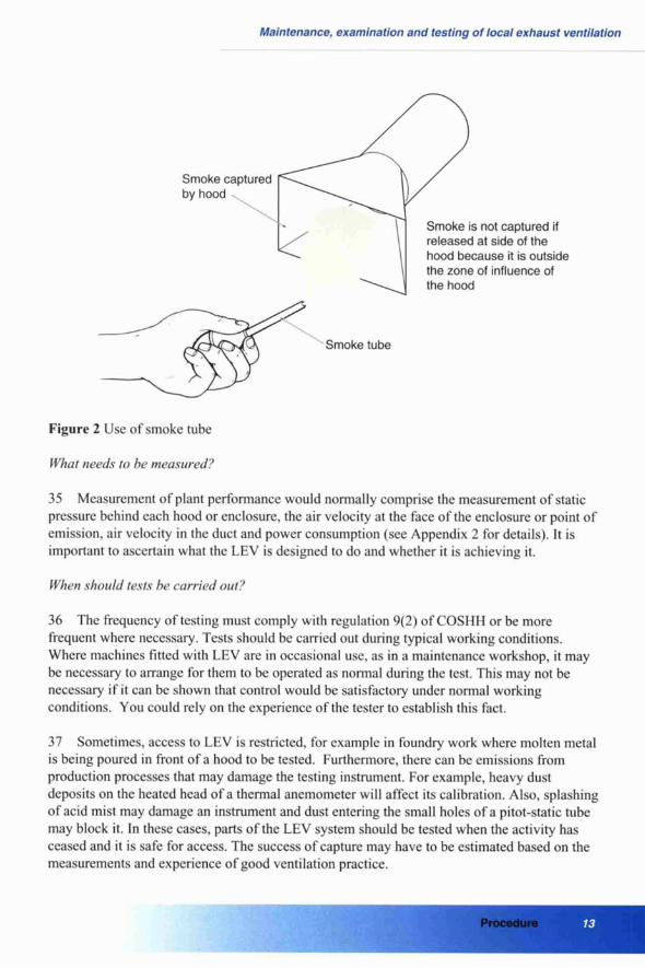
Smoke captured by hood
Smoke is not captured if released at side of the hood because it is outside the zone of influence of the hood
Smoke tube
Figure 2 Use of smoke tube
What needs to he nreasured?
35 Measurement of plant performance would normally comprise the measurement of static pressure behind each hood or enclosure, the air velocity at the face of the enclosure or point of emission, air velocity in the duct and power consumption (see Appendix 2 for details). It is important to ascertain what the LEV is designed to do and whether it is achieving it.
When should tests he carried out?
36 The frequency of testing must comply with regulation 9(2) of COSHH or be more frequent where necessary. Tests should be carried out during typical working conditions. Where machines fitted with LEV are in occasional use, as in a maintenance workshop, it may be necessary to arrange for them to be operated as normal during the test. This may not be necessary if it can be shown that control would be satisfactory under normal working conditions. You could rely on the experience of the tester to establish this fact.
37 Sometimes, access to LEV is restricted, for example in foundry work where molten metal is being poured in front of a hood to be tested. Furthermore, there can be emissions from production processes that may damage the testing instrument. For example, heavy dust deposits on the heated head of a thermal anemometer will affect its calibration. Also, splashing of acid mist may damage an instrument and dust entering the small holes of a pitot-static tube may block it. In these cases, parts of the LEV system should be tested when the activity has ceased and it is safe for access. The success of capture may have to be estimated based on the measurements and experience of good ventilation practice.
Procedure

°_.
L=O
a-
+
-;'
--.
`o.
'fl
Maintenance, examination and testing of local exhaust ventilation
Air returned to the workplace
38 Where air is returned to the workplace there is a danger that if the filter fails, polluted air can affect not only the worker being protected but others in the vicinity. With systems that recirculate filtered air, the following examination and testing should be made:
Provide a rigorous visual examination of the filter for possible damage and to ensure a good seal in its housing. Signs of dust on the clean side will indicate a problem.
Check the pressure drop across the filter; too high a pressure indicates blockage, too low a pressure indicates damage or a poor seal.
Arrange for tests of the quality of the air as it leaves the filter. This may prove difficult. If dusts are being filtered then it may be necessary to sample isokinetically (the air velocity into the sampling probe should be the same as that in the duct). If gases or vapours are being filtered then an analyser can be used. Alternatively, filtered air can be sampled for subsequent chemical analysis. This may require the services of an occupational hygienist.
Test the filters for compliance with published standards especially for `HEPA' (high efficiency particulate air) filters.
39 Some filters are fitted with continuous monitors for returned air quality which may be coupled to alarms. These will require maintenance and calibration in accordance with the manufacturers' instructions.
Making a judgement
40 Based on visual inspections and technical measurements, the tester needs to make a judgement as to whether the system is adequately controlling the substance(s) hazardous to health.
41 The capture effectiveness will be shown by smoke and/or dust lamp tests. But the performance of certain parts of the LEV plant can only be judged by measurement of air velocity, pressure or volume flow rate, for example filter pressure drops, duct transport velocities, fan volume flow rates and pressures.
42 The results of these measurements need to be compared with some or all of the following:
the original data given by the supplier;
the data gathered on the first inspection, if shown to represent a means of achieving good control;
recommended good ventilation practice.
43 One of the purposes of the regular LEV testing is to ascertain whether the system has deteriorated since the previous test. Therefore it is important to compare the current readings with previous ones.
Procedure

-°n
V-.
c00
Maintenance, examination and testing of local exhaust ventilation
Instruments and techniques 44 Various instruments and techniques can be used for the examination and testing of LEV plant. The most common fall into three categories:
direct measurement of emissions (air monitoring);
measurement of plant performance;
visualisation techniques.
Air monitoring
45 Measurement of the airborne concentration in the breathing zone of the workers, in close proximity to the source, may give an indication of the success of the LEV for controlling a substance hazardous to health. This may be needed to comply with regulations 6 and 10 of COSHH. The techniques used are beyond the scope of this guidance but in most instances such testing will require the services of a trained technician.
Measurement of LEV plant performance
Static pressure
46 The measurement of static pressure is relatively easy and is determined by the air flow rate and the resistance of the system due to friction. (See Appendix 3 for a description of techniques).
Air velocity
47 The measurement of air velocity serves two purposes:
measurement of air velocities into hoods etc, or at the working position, will indicate whether the system has the capacity to control the pollutant;
measurement of duct velocity will enable the tester to check whether the system is handling the required air volume, and whether the velocity is high enough to convey pollutant to the collector or point of discharge.
Instruments and techniques

D..
yam..
Maintenance, examination and testing of local exhaust ventilation
48 Air velocities can be measured using various instruments, eg anemometers. Instruments should be carefully selected to ensure that they are accurate and sensitive at the required air velocity and suitable for the purpose (see Appendix 4 for a description of instruments used).
49 Different instruments have their specific limitations, and many commercially available anemometers for field use are not accurate at air velocities below 0.2 m/s.
Flow visualisation devices and tracers
50 Several techniques can be used to visualise the flow of certain pollutants. The most common are the use of smoke generators (to show air flow patterns) and the use of a dust lamp (for use with particulate contaminants). See Appendix 5 for details of the use of flow visualisation techniques.
51 Containment testing can be used in specific circumstances, eg microbiological safety cabinets, to test the effectiveness of exhaust ventilation enclosures. A tracer gas or aerosol is released at a predetermined rate inside the enclosure and then monitored at set points outside to determine if any escaped.
Maintenance and calibration of instruments
52 Apart from liquid-filled manometers, all measuring instruments require servicing and calibration at regular intervals. The intervals for servicing depend to some extent upon the frequency of use. It is recommended that instruments used daily should be serviced at six- monthly intervals, and all others every twelve months. However, if an instrument becomes damaged, it should not be used until it has been repaired or recalibrated.
Instruments and techniques

.U,
a.+
fl.
Maintenance, examination and testing of local exhaust ventilation
Records, reporting and action 53 For the thorough examination and testing to be of practical use, it must be backed up by
an effective system of recording information and a method of ensuring that any faults detected are promptly rectified. The COSHH ACOP' lists in detail the information to be recorded in
respect of each thorough examination and test.
54 There will need to be pro formas for the tester to complete and sign, and to pass to the
appropriate person responsible for the LEV system. If repairs are required then the responsible person will need to ensure that they are carried out promptly. The effectiveness of the repairs should be proven by a retest.
55 To be useful, the information in the record would need to include:
the conditions of the LEV system at the time of the examination and test;
information on the intended performance of the LEV plant and the way it should be used;
methods used to judge the performance of the LEV system and whether it achieves the required performance;
results of routine ventilation measurements;
results of tests of concentration of airborne material;
request for remedial action with details of repairs or modifications needed.
56 In the pro forma, space may be allocated for a diagram of the LEV plant layout to indicate test points, plant location and performance values. This will make the examination, testing and maintenance of the LEV plant easier. It may not be necessary or possible to fill in
every space on the pro forma. However, much of the information it contains is required to compare with measurements taken on the test, and it can be used to form a judgement as to whether the system is still performing as it should.
57 The record of the examination and test should be kept by the employer for at least five years, and a copy should be available at the workplace in which the LEV plant concerned is located.
Records, reporting and action

Maintenance, examination and testing of local exhaust ventilation
Records, reporting and actions

Maintenance, examination and testing of local exhaust ventilation
Appendix 1
Information required of an LEV system This pro forma is an example of recording the data required for monitoring an LEV system. For more detailed information, you should consult the COSHH ACOP`.
Name and address of company
Department or site
Location of plant
Identification of plant
Hazardous substances controlled by plant
Type of plant (see also section on sketch of plant layout)
Appendix 1 Information required of an LEV system

Maintenance, examination and testing of local exhaust ventilation
Fan specification (provided by the supplier)
Fan details: maker serial no
Fan type (eg guide vane, bifurc, Max design speed forward bladed) Axial rpm Centrifugal
Fan speed rpm Motor: maker speed rpm
Drive type Motor power direct v-belt other kW
Duty: Volume flow rate m'/s Voltage phase Static or total pressure Pa Air power kW
Inlet dia mm Full load current Outlet dimensions mm amp
Primary air cleaner details: * Static pressure Test
Maker inlet Pa
Serial no outlet Pa
Filter area m2 across Pa
Design volume flow m3/s change at Pa
* same will apply for second air cleaner
Appendix 1 Information required of an LEV system

E
C
C E
Maintenance, examination and testing of local exhaust ventilation
Identification and location of system
Sketch of plant layout: label ventilation plant items and number measurement positions
Inlet points, showing the design values for performance (see sketch)
Point no
Type of inlet
Face dimensions (mm)
Duct dia (mm)
Area
(m)
Face vel (m/s)
Duct vel (m/s)
Flow rate (m'/s)
Comments
Appendix 1 Information required of an LEV system

a., E
Maintenance, examination and testing of local exhaust ventilation
Results of routine ventilation measurements Test values for inlet points
Point Date Static pressure (Pa)
Air velocity (m/s)
Volume flow (m'/s)
Instrument used
Comments
Conditions at time of test
Results of visual inspection Describe any defects found in any parts of the ventilation system and state what remedial action is required
Measurements/inspection made by
Name
Date
Appendix 1 Information required of an LEV system

F-'
II.
Maintenance, examination and testing of local exhaust ventilation
Appendix 2 Measurement of plant performance The measurement of plant performance would include:
Enclosures - measuring the negative static pressure between the inside of the enclosure and the workroom to check whether it is negative.
Booths/fume cupboards - taking the air velocity on all openings where pollutants can escape into the workroom, ie face velocity. It may be necessary to divide the opening into imaginary equal area rectangles, take a velocity reading in the centre of each and take an average of those velocities. This is useful to ascertain how evenly distributed the air flow is (known as velocity profile). Ideally any one reading should not be more than 20% greater or less than the average. Fume cupboards and microbiological safety cabinets can also be further tested according to appropriate BS or CEN Standards. (Figure 3 shows an example of measurements being taken.)
Hoods, canopies - in addition to the smoke or dust lamp checks, the face velocity should be measured. As with booths above, where the hood or canopy is large, it may be necessary to divide the opening into imaginary rectangles and take a velocity reading in the centre of each. Also, it may be useful to measure a static pressure in the duct serving this unit about four duct diameters downstream from where it is connected.
Slots - as these can be long and narrow it will be necessary to take air velocity readings at equidistant points along the entire length. The readings should be averaged, but in a well- designed system no individual reading should be more than 20% above or below the average. Also, it may be useful to measure a static pressure in the duct serving this unit close to where it
is connected, or if the slot is on the side of a plenum (enclosure behind the slot) then the plenum static pressure could be measured.
Ducts - where possible, take the air velocity in each duct serving the capture device. A straight section of duct should be chosen well downstream of bends and other sources of turbulence.
Fans - measuring the static pressure at inlet to the fan and the volume flow rate passing through the fan. The volume flow rate could be measured on the inlet or outlet of the fan
Appendix 2 Measurement of plant performance

Maintenance, examination and testing of local exhaust ventilation
provided there is a reasonably straight section of duct in which to take the readings, ie well downstream of sources of air turbulence. If the fan is v-belt driven, it is advisable to measure the number of revolutions of the fan shaft with a tachometer.
Filters - checking the static pressure at the inlet, outlet and hence across the filter. If it has a fabric filter medium and a shake down cleaning device, it is advisable to operate the shake down prior to taking any air flow measurements in the system. Where pressure gauges are fitted to a filter, their accuracy should be measured by comparing them with a recently calibrated pressure gauge. Normally the volume flow rate passing through the fan should be the same as that passing through the filter, but if it is not then the filter flow rate should be measured.
Special filter tests - with highly toxic dusts the quality of filtration must be of a very high standard, and high efficiency filters ('HEPA' or `absolute' filters) are used. Their efficiency may have to be tested in situ according to a procedure following the appropriate British, European or ISO standard, which may involve a specialist tester.
Wet scrubbers - measuring static pressure at inlet and outlet, and value of water pH if that is essential to the scrubbing operation.
Face of booth divided into imaginary rectangles
---------------------------------------
Meter Meter placed in midpoint of each rectangle
Air velocity is measured at a series of positions across the face of the booth
Figure 3 Measurement of face velocity on a booth
Appendix 2 Measurement of plant performance

r°.
FL-
..+
Maintenance, examination and testing of local exhaust ventilation
Appendix 3 Measurement of static and velocity pressure Static and velocity pressure techniques
Static pressure (see Appendix 6) is measured at right angles to the direction of air flow so as not to be affected by air velocity. Holes will need to be drilled or nozzles brazed to the side of the duct at the appropriate places, ie in the duct behind a hood, at the inlet and outlet of a
filter, at the inlet to a fan. Measurements are taken by connecting a pressure gauge to the nozzle or side tube of a pitot-static tube inserted in a hole by means of flexible tubing. The bore size is normally about 6 mm but some instruments take narrower bore tubing.
Velocity pressure is a means of determining air velocity in ducts. It is measured by means of a pitot-static tube (described later) connected to a pressure gauge. This pressure has to be converted to velocity using an equation given in Appendix 6. Holes of no more than 10 mm diameter are drilled in the duct, at the point where an air velocity is required, being careful to avoid places too close to a source of turbulence. The pitot-static tube is inserted through the hole and is pointed so that the air blows into the central hole and the side holes are at right angles to the flow. A sketch of a pitot-static tube is shown in Figure 4.
Instruments for measuring static pressure
The most convenient pressure gauges (manometers) are either:
- electronic, containing a pressure transducer;
- mechanical, containing a pressure sensitive diaphragm;
- liquid in glass, vertical or inclined.
These instruments usually have two nozzles, one for positive and the other for negative pressure. These are usually labelled.
The gauges can be calibrated in a variety of units - Pascals, mm of water, millibars, inches of water - but the SI unit of Pascal is preferred. The range of such instruments should be from
Appendix 3 Measurement of static and velocity pressure

to=
w..
Maintenance, examination and testing of local exhaust ventilation
0-5000 Pa (Pascal), in increments of 50 Pa between 0-500 Pa and then in increments of 5 Pa. This may mean having more than one instrument to obtain the full range and precision.
Liquid filled gauges are available and can be extremely precise. However they are difficult to use as the base of the instrument has to be truly horizontal, and there is a risk of air bubbles forming in the liquid. Liquid can be sucked or blown out of the instrument by careless connection to a pressure that is too high. Furthermore, they are bulky and take care and time to obtain a reliable reading. However if tests have to be made requiring precision to the level of a British or ISO Standard, then they should be used as they are inherently free of calibration problems.
Liquid manometers and mechanical diaphragm gauges require no electrical power and can be used in flammable atmospheres.
Annular openings measure static pressure (Ps)
Front opening measures total pressure (Pt), ie the sum of static pressure (Ps) and dynamic (velocity) pressure (Pd)
Direction of airflow
Alignment arm
Manometer
Note: The manometer measures dynamic pressure Pd, ie difference between total pressure (Pt = Pd + Ps) and static pressure (Ps). Air velocity (V) is calculated from V=1.29 IPd Where V is m/s and Pd is in Pascals (readings at 20°c and 1.013 bar)
Figure 4 Pitot-static tube
Appendix 3 Measurement of static and velocity pressure

,.0
(CC
[z.
CL)
Maintenance, examination and testing of local exhaust ventilation
Picot-static tube for measuring static and velocity pressure
This is illustrated in Figure 4 and consists of two concentric tubes. The inner tube has a front opening which is pointed into the flow. The outer tube is sealed at the front but has annular openings around the periphery. When the central tube is pointing into the air flow the annular openings are at right angles to the flow direction. At the other end each tube has a separate nozzle to which plastic or rubber tubing can be attached. When the two nozzles are connected to each side of the gauge the reading is indicating velocity pressure or dynamic pressure.
If a static pressure is required, the gauge is connected to the outside tube only and provided the pitot-static tube is placed correctly, the gauge will show static pressure.
If velocity pressure is required, both nozzles should be connected to the pressure gauge, the central tube being connected to the positive side and the outside tube connected to the negative side of the pressure gauge. When the pitot-static tube is placed in the duct as shown in Figure 4, the gauge will indicate velocity pressure. This value can then be converted to velocity by using the appropriate equation given in Appendix 6. Some pressure gauges have the facility to convert velocity pressure to velocity electronically.
Simultaneous measurement of static pressures at various positions in the system may enable the different parts of the LEV system to be monitored (see Figure 5).
Appendix 3 Measurement of static and veloc

0
0
0
Maintenance, examination and testing of local exhaust ventilation
Test point 3 LTest point 4
Test point 1 Test point 2 (negative) (positive)
(negative) (negative) Duct
Exhaust
J collector Fan
hood or filter
Static pressure at test point compared Typical fault with normal
1 2 3 4
Normal Normal Normal Normal System operating normally
Low High High Low Blockage in duct or closed damper between points 1 and 2
Low Low High Low Blocked filter dust collector
High High Low High Missing or damaged filter Low water level in wet dust collector
Low Low Low Low Faulty fan; incorrect fan speed, slipping drive belts, deposits on or damaged blades, incorrect electrical wiring
High High High Low Build-up of dust and debris in, or blockage of,
hood etc
Low Low Low High Blockage in exhaust stack
Figure 5 An example of the use of static measurements for fault finding in a simple exhaust ventilation system
Appendix 3 Measurement of static and velocity pressure

inn.
.
CDw
Maintenance, examination and testing of local exhaust ventilation
Appendix 4 Air velocity measurement MEASUREMENT
Air velocity can be measured using various instruments.
Air velocities within ducts above 3 m/s can be measured by the pitot-static tube and gauge as described in Appendix 3, but velocities below 3 m/s and in places outside ducts need to be measured by other means. These include:
- rotating vane anemometers which look like windmills with diameters from 15 mm up to 150 mm (see Figure 6);
thermal anemometers which are thin probed with a sensing head at one end;
swing vane anemometers which are bulky and tend to distort the flows being measured.
These types of instrument are connected to a meter either rigidly or via a flexible cable, and are normally calibrated in metres per second (m/s) or feet per minute (ft/min) or both. The SI unit of m/s is preferred.
Rotating vane anemometers are sensitive to flow direction and can be used to determine air flow direction. They lose precision at velocities below 0.25 m/s. Some are mechanical devices where the number of turns of the vanes are timed by a stopwatch or other timing device. From this the air velocity is calculated. This type can be used in flammable atmospheres as there is no electrical power required. More commonly the meters are electrically powered, counting electrical pulses created by the vanes as they rotate. Electrical vane anemometers are available in an intrinsically safe version if required.
The vanes on these anemometers are carefully angled and the rotor is delicately balanced on jewelled bearings. They require careful handling so as not to disturb their settings. On no account should the vanes be touched or placed on a surface where projections touch them. If there is any reason to suspect that the vane angles have been altered or the balance of the rotor affected, then they should be returned to the maker for repair and recalibration.
Rotating vanes are not ideal for measurement in ducts as the size of hole required to insert them can be quite large. Nor are they suitable for measurement of air velocity in narrow
Appendix 4 Air velocity measurement

..t
(AD
Ll.
,ti
Maintenance, examination and testing of local exhaust ventilation
slots or small openings, as it is necessary for the head of the instrument to be narrower than the opening being measured. Furthermore the presence of a bulky instrument may alter the velocity and direction of the air flow being measured.
Thermal anemometers have a heated sensing head which responds to the cooling power of air flow. Most types have a second sensor which compensates for air temperature. They should not be used in flammable atmospheres as an electric current is passed through the sensing head. Neither can they be used to determine the direction of air flow unless the head is specially shielded. They lose precision at about 0. I m/s. Thermal anemometers can be used for measurement inside ducts as they are sufficiently narrow to be inserted into a small hole.
As they are narrow, these instruments are ideal for measurement in small openings such as slots and they disturb the airflow patterns far less than the more bulky vane anemometers.
Swing vane anemometers are cumbersome to use and a range of fittings are needed for different applications.
Figure 6 Typical vane anemometer used to measure air velocity
Appendix 4 Air velocity measurement

'0'
'L7
Maintenance, examination and testing of local exhaust ventilation
Appendix 5 Use of flow visualisation techniques Flow visualisation techniques
Smoke is a very useful guide to seeing where air is flowing. It is particularly useful around the mouths of hoods, canopies and slots to see the distances from which the hood can draw air. It is useful for releasing inside a booth or enclosure to see if the face velocity or negative pressure is sufficient to prevent air from escaping. You can also observe the air turbulence around the edges of booths.
There are several devices that can be used to generate smoke depending upon the amounts required.
Small scale - air current tubes are available which consist of glass tubes 6 mm in diameter and 100 mm in length. These contain crystals which fume with a white smoke when air is passed through them. The technique is to break the sealed ends of the tube and attach a small rubber puffer to one end. As the puffer is squeezed a cloud of white smoke appears at the other end. This smoke is then puffed around the areas to observe the flow patterns. The smoke produced is not very stable and quickly disperses or disappears.
Medium scale - theatrical smoke producers are useful for observing the success of control of booths and fume cupboards. They can be used to identify the stacks of these devices when the duct runs are not easily traced within a building. The most common types of device have a heated plate, a fan and generally an outlet nozzle of 100-150 mm diameter. Oil or a liquid containing glycerol is dropped on to the hot plate. This produces large amounts of white smoke which are blown out through the nozzle by means of the fan. The smoke produced is reasonably stable and will remain visible for several minutes. It will survive being drawn through ductwork and fan to appear at the top of the stack.
A useful technique using this type of smoke producer is to place it inside a booth or fume cupboard, set it running and stand sideways to the face of the booth to see whether the smoke is contained.
Appendix 5 Use of flow visualisation techniques

tea,
0000,
Abp
Maintenance, examination and testing of local exhaust ventilation
Large scale - companies that manufacture fireworks produce smoke bombs which are lit with a flame to release copious quantities of stable coloured smoke. These devices are released inside large buildings to trace the path of air as it leaves the building through extract ventilation systems and roof fans. This is to see whether the extracted air re-enters the building. This test is normally undertaken at a weekend when staff are absent.
Warning - care should be taken with the use of these devices as some people may react to the smoke produced. Smoke from some generators may contaminate surfaces. Furthermore, all these smoke producers will activate smoke alarms, therefore the alarms should be temporarily deactivated before use.
The dust lamp (Tyndall beam)
When a strong beam of light is passed though a cloud of dust particles, the light is scattered making the particles more visible. This is more pronounced if the background is dark and you view the particles by looking towards the lamp, but shielding your eyes against direct glare.
Spot lamps with an elliptical reflector make the ideal source, but they need to be portable and they are usually battery powered. The light source needs to be on a stand, such as a tripod or clipped to a girder, so that it can be directed into a cloud of dust being released from a production process. If the lamp is positioned correctly, it is possible to observe the movement of dust in relation to the mouth of the extract system and the breathing zone of the operator. From this a judgement can be made on the success of capture.
HSE has produced a guidance note on the use of the dust lamp (MDHS82').
Appendix 5 Use of flow visualisation techniques

(<D
vi
i
f1.
s..
'fl
Maintenance, examination and testing of local exhaust ventilation
Appendix 6 Equations used in LEV testing Air density, symbol p, unit kg/m' (kilogramme per cubic metre)
Standard air density is 1.2 kg/m'. This corresponds to air at 20°C and 1013 mb barometric pressure.
For most occasions it will be possible to use standard air density, as most LEV systems handle air at close to standard conditions. However, should the air be hot or the location be in a deep mine or at altitude above 1000 m, it may be necessary to correct for the actual air density using the following equation:
1.2 x 293 x b pb = kg/m'
(273 + t) x 1013
where: b = barometric pressure in mb, t = air temperature in °C and p,, = air density at barometric pressure b and temperature t.
Air velocity, symbol v, unit m/s (metres per second)
When air velocity is measured using an anemometer it is usually indicated on the meter. When a pitot-static tube and manometer are used it may be necessary to calculate the air velocity.
Note: some pressure gauges have the facility to display velocity directly when connected to a
pitot-static tube, either at standard air density or at a pre-calculated density, having first entered the barometric pressure and air temperature.
Appendix 6 Equations used in LEV testing

(IQ
CA
D
Maintenance, examination and testing of local exhaust ventilation
The equation for calculating air velocity from a picot-static tube reading, known as velocity pressure or dynamic pressure symbol p, and expressed in units of Pascal (Pa), which is the same as Newtons per square metre.
V = 2 (s)2S or v= square root of the result of taking two times p, divided by p. If p is at standard density of 1.2 kg/m' then the equation can be simplified to: v = 1.29J p m/s or v = 1.29 times square root of p,.
Volume flow rate, symbol Q, unit m'/s (cubic metres per second)
Volume flow rate is calculated by measuring the average air velocity at a location and multiplying that by the cross-sectional area of the airway at that location:
Q = v x A m3/s where A = cross-sectional area in m2 (square metres).
Note: as air moves faster in the centre of a duct than it does close to the edges, it may be necessary to take several readings across the duct and make an average of those results. The exact positions are defined in British Standard 848. However, for LEV tests under COSHH it may not be necessary to be so precise unless the measuring station is near to a source of turbulence. A centre reading of velocity multiplied by 0.85 will give a satisfactory approximation of the average velocity.
Area, symbol A, unit m' (square metres)
With circular ducts, the cross-sectional area is calculated by measuring the duct diameter in metres and substituting it in the equation:
A= - m2
4 where d = duct diameter in metres (not millimetres).
Static, total and velocity pressure
Static pressure is, in effect, the difference in barometric pressure between two points but expressed in the more precise unit of Pascal rather than mb. It is measured at right angles to the flow.
Total pressure is the sum of static and velocity pressure and is measured into the flow. Static pressure can be either positive or negative but velocity pressure is always positive.
Velocity pressure represents the kinetic energy of moving air.
Appendix 6 Equations used in LEV testing

Maintenance, examination and testing of local exhaust ventilation
References
1 An introduction to local exhaust ventilation HSG37 HSE Books 1993 ISBN 0 7176 1001 2
2 Occupational exposure limits 2002 EH40/2002 HSE Books 2002 ISBN 0 7176 2083 2
(to be read in conjunction with Occupational exposure limits supplement 2003 ISBN 0 7176 2172 3)
3 Control of substances hazardous to health. The Control of Substances Hazardous to Health Regulations 2002. Approved Code of Practice and guidance L5 (Fourth edition) HSE Books 2002 ISBN 0 7176 2534 6
4 Management of Health and Safety at Work Regulations 1999 SI 1999/3242 The Stationery Office 1999 ISBN 0 11 085625 2
5 Work with asbestos which does not normally require a licence. Control ofAsbestos at Work Regulations 2002. Approved Code of Practice and guidance L27 (Fourth edition) HSE Books 2002 ISBN 0 7176 2562 1
6 Control of lead at work. Control of Lead at Work Regulations 2002. Approved Code of Practice and guidance L132 (Third edition) HSE Books 2002 ISBN 0 7176 2565 6
7 The dust lamp: a simple tool for observing the presence of airborne particles MDHS82 HSE Books 1997 ISBN 0 7176 1362 3
Other publications
American Conference of Governmental Industrial Hygienists Industrial ventilation: A manual of recommended practice 23rd edition ACGIH 1998 ISBN 1 8824 1722 4
Ashton I and Gill F S Monitoring for health hazards at work Blackwell 1999 ISBN 0 6320 0504 11
British Occupational Hygiene Society Controlling airborne contaminants in the workplace BOHS Technical Guide 7 Science Reviews 1987 ISBN 0 9059 2742 7
Harrington J M and Gardiner K Occupational hygiene Blackwell 1995 ISBN 0 6320 3734 2 (Chapter 22 Ventilation)
Accreditation for the inspection of local exhaust ventilation (LEV) plants RG4 UKAS 2000
While every effort has been made to ensure the accuracy of the references listed in this publication, their future availability cannot be guaranteed.

0
Maintenance, examination and testing of local exhaust ventilation
Printed and published by the Health and Safety Executive C30 Reprinted 1/04

0
(/j
Egki HSE BOOKS
MAIL ORDER HSE priced and free publications are available from: HSE Books PO Box 1999 Sudbury Suffolk CO10 2WA Tel: 01787 881 165 Fax: 01 787 3 13995
Website: www.hsebooks.co.uk
RETAIL HSE priced publications are available from booksellers
HEALTH AND SAFETY INFORMATION HSE InfoLine Tel: 08701 545500 Fax: 02920 859260 e-mail: [email protected] or write to: HSE Information Services Caerphilly Business Park Caerphilly CF83 3GG
HSE website: www.hse.gov.uk
Price £8.50
ISBN 0-7176-1485-9
9 780717"611851
HSG54