testing of the voice communication in smart home care open access testing of the voice communication...
TRANSCRIPT

Vanus et al. Human-centric Computing and Information Sciences (2015) 5:15 DOI 10.1186/s13673-015-0035-0
RESEARCH Open Access
Testing of the voice communication insmart home care
Jan Vanus*, Marek Smolon, Radek Martinek, Jiri Koziorek, Jan Zidek and Petr Bilik* Correspondence: [email protected] of Cybernetics andBiomedical Engineering, Faculty ofElectrical Engineering andComputer Science, VSB –TechnicalUniversity of Ostrava, 17. listopadu,15/2172, Ostrava 708 33, CzechRepublic
©(p
Abstract
This article is aimed to describe the method of testing the implementation of voicecontrol over operating and technical functions of Smart Home Come. Custom controlover operating and technical functions was implemented into a model of Smart Homethat was equipped with KNX technology. A sociological survey focused on the needs ofseniors has been carried out to justify the implementation of voice control into SmartHome Care. In the real environment of Smart Home Care, there are usually unwantedsignals and additive noise that negatively affect the voice communication with thecontrol system. This article describes the addition of a sophisticated system for filteringthe additive background noise out of the voice communication with the control system.The additive noise significantly lowers the success of recognizing voice commands tocontrol operating and technical functions of an intelligent building. Within the scopeof the proposed application, a complex system based on fuzzy-neuron networks,specifically the ANFIS (Adaptive Neuro-Fuzzy Interference System) for adaptivesuppression of unwanted background noises was created. The functionality of thedesigned system was evaluated both by subjective and by objective criteria(SSNR, DTW). Experimental results suggest that the studied system has the potentialto refine the voice control of technical and operating functions of Smart Home Careeven in a very noisy environment.
Keywords: Voice Recognition; Additive Noise; ANFIS; .NET Framework; Microprocessor;Synthesis; Fieldbus; KNX; ETS; C#
IntroductionTechnologies that help seniors to live a quality life and to be more self-sufficient in
everyday life are being developed. One of the fields of this development and innovation
of modern technologies is Smart Home [1] to ensure independent living for senior
citizens or disabled persons in household environment with the option of assistance
care (Smart Home Care).
A sociological survey has been carried out to find out the needs of seniors [2] in the
field of modern technology. The survey was aimed towards persons over 45 years old
and thus also towards people that are not yet in senior age. The total number of
respondents was 98. The goal of the survey was to find out what attitude towards
modern technology not only seniors, but also middle-aged people preparing for
retirement have. The survey shows that seniors use technology more and more.
Prejudices and fears of new machines and devices fall. The survey was handed
out in homes for the elderly, in nursing homes and to people living in private
2015 Vanus et al. This is an Open Access article distributed under the terms of the Creative Commons Attribution Licensehttp://creativecommons.org/licenses/by/4.0), which permits unrestricted use, distribution, and reproduction in any medium,rovided the original work is properly credited.
Vanus et al. Human-centric Computing and Information Sciences (2015) 5:15 Page 2 of 22
homes. Conditions that have often occurred in the survey replies for the use of
modern technology in personal lives of seniors were as follows: “the need to
understand modern technology, easy usability of the technology, usefulness of the
technology for everyday life”.
Many homes for the elderly in the Czech Republic are nowadays equipped with at
least basic safety devices like cameras, smart cards registering the departure and arrival
of inhabitants, fire detectors, alarms and so on. The vast majority of seniors are
equipped with a mobile phone, especially for the feeling of their own safety and the
possibility to contact quickly the person close to them. For the purpose of illustration,
here are answers to some questions. Respondents answered the following question:
“If I could to choose, I would like to live in” as follows:
� 69 % of the respondents are satisfied with their current situation in terms of living
and would not want to change it,
� 5 % of respondents would want to move from a home for the elderly or a nursing
home to a private home,
� 4 people (4 %) would move to a home for the elderly in the future and
� 6 people (6 %) would move to a nursing home,
� 16 people (16 %) would live in an intelligent house.
To increase the safety inside residential premises, most of the respondents would use:
� CCTV in common areas (64 %)
� A SOS button (56 %)
� Sensor equipment (smoke detectors, gas and water leakage detectors), (43 %)
� Medical equipment (check of physiological functions) along with
� Cameras in private areas scored the least points (13 % and 2 %)
The respondents answered the question about the comfortable way to control operat-
ing and technical functions of Smart Home as follows:
� 46 % of respondents still prefer manual control over the house/apartment
� 24 % of respondents would want to control Smart Home by voice
� 12 % of them would control it via a computer
� 8 % by touchscreen and
� 10 % of respondents would use it through portable devices
Based on the preference of voice control over the operating and technical functions
of Smart Home Care, a voice control system was designed to control the operating and
technical functions in the real environment of Smart Home Care. This system was later
presented inside the laboratories of VŠB-TU Ostrava on a model with implemented
KNX technology (Fig. 6).
In real-life implementations of the designed systems for voice communication [3-6]
with the control system it is necessary to resolve an issue with additive noises for the
particular environment [7,8]. Voice control in smart apartments is preferred mainly by
older or handicapped fellow-citizens [9]. This paper focuses on the design and

Vanus et al. Human-centric Computing and Information Sciences (2015) 5:15 Page 3 of 22
implementation of a comfortable voice control operational and technical functions in
intelligent building with the KNX technology system. The whole work could be notion-
ally divided into three parts, namely the development of applications for voice recogni-
tion, programming and animation has finished school model and implementation of a
communication interface between these parts. The actual recognition of voice com-
mands will be implemented on the platform. NET Framework 4.0 using C# program-
ming language. Recognition results in machine code will be sent over UDP server using
KNX / IP router from the host to the school model. After completing work on a model
of intelligent building and a successful implementation of voice control is carried out
functional and quality voice recognition testing.
The task of the designed software G.H.O.S.T for voice control of operational tech-
nical functions of a Smart House is to provide users with easy and simple access to
control of their house. This application can serve as a complement to other technolo-
gies, supporting Tele Care in Smart Home Care. For example, for determining the pos-
ition of the senior citizen’s in Smart Home Care [10].
Description of development environment
The application has been created in “Sharp Develop” environment, which is an open
source integrated development environment.
Application appearance and basic features
After launching G.H.O.S.T application, an introductory screen with basic menu (Fig. 1)
is presented to the user.
In the upper part of the screen there is a button in form of an icon with a micro-
phone, which serves for turning off and on of voice recognition. The basic menu con-
sists of six buttons (Visualization, “Statistics”, Voice commands, Settings, Help and
Close) providing switching to other screens. Each of the submenus provides the user
with the possibility to control functions of Smart Home Care or the G.H.O.S.T pro-
gram itself.
Visualization screen - Contains floor plan of the apartment controlled by KNX sys-
tem displaying system status (Fig. 2). Icon indicating status of lighting and status of
drawing down or up of the blinds has been inserted to every room.
Fig 1 Appearance of the introductory screen

Fig 2 Application appearance - Visualization Screen
Vanus et al. Human-centric Computing and Information Sciences (2015) 5:15 Page 4 of 22
Indication of blinds movement relates to bedroom, kitchen and living room, where
these components are used. After entering a particular voice command, the application
is able to evaluate the command and visualize the changes performed on this screen.
Statistics screen - Enables the user to test quality of voice recognition (Fig. 14).
Voice commands screen - Serves for checking the required commands (Fig. 3). The
individual recognized commands are listed in Rich Text Box component. Moreover, if
the expression or phrase correctly recognized, it is listed in the main caption. Each rec-
ognized command has been updated with information notifying about success rate with
which the command was recognized.
Settings screen - provides settings of behavior of the two basic components -
synthesizer and voice recognizer (Fig. 4). For synthesis, speed of speech, speech volume
and phrase with which the system will address the user can be set. For voice recogni-
tion, phrases for turning on and off voice recognition can be chosen.
Fig 3 Application appearance – Voice Commands Screen

Fig 4 Application appearance - Settings Screen
Vanus et al. Human-centric Computing and Information Sciences (2015) 5:15 Page 5 of 22
Help screen - contains brief description of the individual tabs and their functions.
Individual commands for voice control that have been used are also listed here.
There are two ways to quit the application: either by a voice command, or by clicking
the Close button.
Application structure and description of source codes
The internal function of G.H.O.S.T application is illustrated below in form of a UML
scheme. The application has been developed using object-oriented language C# on
.NET 4.0 platform. The resulting application is designed in “Sharp Develop” environ-
ment so that at first the respective graphical part of the program is designed (the re-
quired components are arranged in the application window, their style and proper-ties
are created) and then these graphical elements are assigned certain functions in text
editor. Because the developed program uses a greater amount of graphical elements, it
logically contains quite a large amount of service methods. Listing all methods would
not be very synoptic in a single UML scheme. In order to clarify application functions,
a simplified UML scheme is showed in Fig. 5.
The full extent of the graphical part roughly consists of a hundred graphical compo-
nents. The text part, which implements main functionality of the whole application
(Fig. 6), spreads out in about seven hundred lines of suitably commented code.
As apparent from the generated UML scheme, two basic classes have been set in the
application. The first one is “Main Form” class, which inherits its basic properties from
“Form” class. This class can be labelled as main, as it contains majority of methods pro-
viding program functionality. The other class named “Voice commands” has been gen-
erate only for the purpose of increasing lucidity of the written program. After the
program is started, initial configuration of the program is performed using method
“Main Form Load ()”. In the initialization method, import of settings from an external
file is performed first and then the voice recognizer and synthesizer are set. “Main

Fig 5 Simplified program UML scheme
Vanus et al. Human-centric Computing and Information Sciences (2015) 5:15 Page 6 of 22
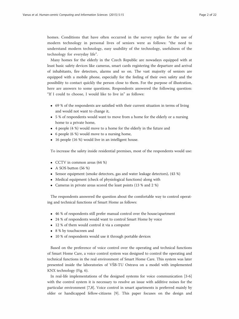
Form Load ()” initialization method also includes a block marked as Microsoft SAPI
initialization in the scheme (Fig. 7).
Automatic selection of the used micro-phone, creation of a simple dictionary of op-
tions containing only an option for waking the system up from sleep and starting voice
recognition takes place here. In the end of the method, asynchronous voice recognition
is started. During recognition of the wake up phrase, the program automatically per-
forms voice recognition method called “_speech_recognizer_recognized ()”. This
method contains the key algorithm for voice recognition (Fig. 8). Here it is possible to
work with the recognized words stored in memory. A “foreach” type loop has been in-
corporated in the method, whose task is to store all recognized words into buffer.
The UML scheme – Public Partial Class MainForm - Visualization is described in
Fig. 9.
Figure 10 shows how the UML scheme – Public Partial Class MainForm - Program
settings has to be performed.
Fig 6 Testing of the facility
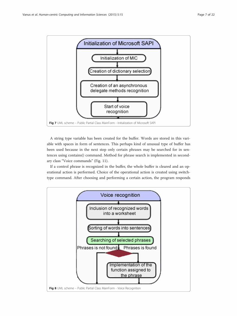
Fig 7 UML scheme – Public Partial Class MainForm - Initialization of Microsoft SAPI
Vanus et al. Human-centric Computing and Information Sciences (2015) 5:15 Page 7 of 22
A string type variable has been created for the buffer. Words are stored in this vari-
able with spaces in form of sentences. This perhaps kind of unusual type of buffer has
been used because in the next step only certain phrases may be searched for in sen-
tences using contains() command. Method for phrase search is implemented in second-
ary class “Voice commands” (Fig. 11).
If a control phrase is recognized in the buffer, the whole buffer is cleared and an op-
erational action is performed. Choice of the operational action is created using switch-
type command. After choosing and performing a certain action, the program responds
Fig 8 UML scheme – Public Partial Class MainForm - Voice Recognition
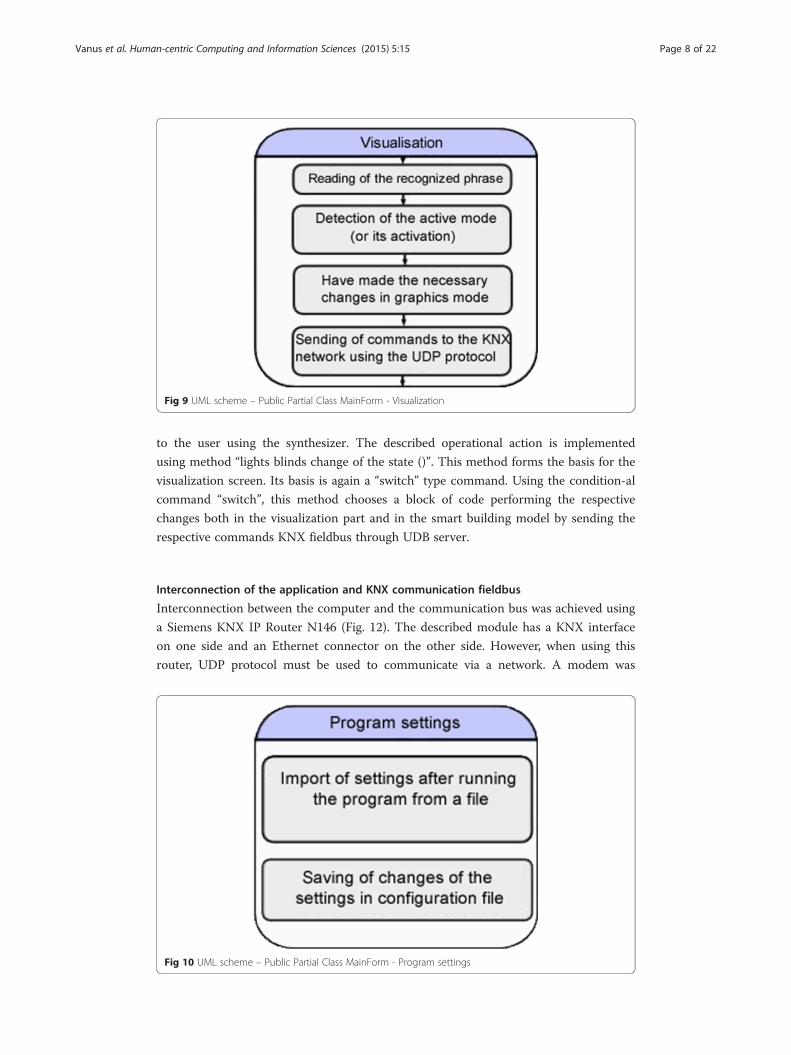
Fig 9 UML scheme – Public Partial Class MainForm - Visualization
Vanus et al. Human-centric Computing and Information Sciences (2015) 5:15 Page 8 of 22
to the user using the synthesizer. The described operational action is implemented
using method “lights blinds change of the state ()”. This method forms the basis for the
visualization screen. Its basis is again a “switch” type command. Using the condition-al
command “switch”, this method chooses a block of code performing the respective
changes both in the visualization part and in the smart building model by sending the
respective commands KNX fieldbus through UDB server.
Interconnection of the application and KNX communication fieldbus
Interconnection between the computer and the communication bus was achieved using
a Siemens KNX IP Router N146 (Fig. 12). The described module has a KNX interface
on one side and an Ethernet connector on the other side. However, when using this
router, UDP protocol must be used to communicate via a network. A modem was
Fig 10 UML scheme – Public Partial Class MainForm - Program settings

Fig 11 UML scheme – Public Class Voice_commands
Vanus et al. Human-centric Computing and Information Sciences (2015) 5:15 Page 9 of 22
added between the computer and the KNX IP Router in order accomplish automated
assignment of IP addresses.
Connection of the entire communication network
Connection is very simple if is consider the wiring connection alone. Much more diffi-
cult is the need to adapt software to individual protocols (KNX and UDP). A slight dis-
advantage is also the fact that the used KNX/IP router module uses rather the simple
UDP communication protocol, which does not guarantee transfer reliability. However,
for this developed application this solution is more than sufficient. Difference between
TCP and UDP protocol is described follow. TCP is a connection-oriented protocol which
means that to establish “end-to-end” communication it requires so-called “handshaking”
to occur between the client and server. After a connection is established, data may be
transferred in both directions.
On the screen (Fig. 13) we can see that a command which requires a press of a but-
ton was sent. The message is in the form of hexadecimal digits:
IP adress: 224.0.23.12
Message content: 06:10:05:30:00:11:29:00:bc:d0:11:1a:09:01:01:00:81
Implementation of interconnection directly in the G.H.O.S.T application
The KNX technology uses its own communication protocol for communication be-
tween the individual peripheral devices. The algorithm to generate codes sent over the
fieldbus would be very complicated and the whole solution would be quite
Fig 12 Connection of the whole communication network

Fig 13 A sample demonstrating IP address and UDP message mapping
Vanus et al. Human-centric Computing and Information Sciences (2015) 5:15 Page 10 of 22
cumbersome. In-put data in form of component addresses and states of the individual
modules are not fully static parameters and may be changed using ETS application. That
is why a more straightforward way was chosen. The used way is based on mapping IP ad-
dresses and UDP messages being sent over the fieldbus on every change on the sensor
part of the system. The Wire Shark application version 1.10.5 was very helpful in this ap-
plication. Only a UDP client was programmed in the developed application, which is able
to send these basic messages in hexadecimal format. Therefore the application can emu-
late pressing of any key through software (it is able to emulate any change both in the sen-
sor part and in the operational part of the system). This way it was possible to get around
the complicated generating of messages based on variable messages and to control the
whole system in the most straightforward and in principle the most natural way for the
fieldbus. A total of 31 similar operational actions were mapped into the application.
Experimental part - testing and command recognition success rate statistics
Testing is a part of the created application. Fig. 14 illustrates an example of testing ap-
plication, where setting of number of repetitions and selection of the tested command
can be seen. After the test is completed, a notification window is displayed with infor-
mation about the particular test. Although the number of well recognized commands is
one hundred of one hundred, the average recognition success rate is only 94.61 %. This
is because the number of recognized words is a real value, while average recognition
success rate represents a program-wise estimated recognition success rate. Ambient
noise, which influences the very recognition, is a major factor that has a great influence
on aver-age recognition success rate. 10 persons of different sex and age have participated

Fig 14 Testing Application
Vanus et al. Human-centric Computing and Information Sciences (2015) 5:15 Page 11 of 22
in testing of this system. Both men and women in age range of 22 – 50 years. An inte-
grated microphone, which is a part of a PC, and a wireless microphone (Logitech Wireless
Headset H600) have been used for testing. Every speaker tested a random voice command
several times. Each of the ten speakers has tested the given command, in the first case
(lights on) 100 times. In order to compare results of the individual speakers, testing was
performed on the same command for each of them. The result is an average percentage
success rate of the tested command and real recognition success rate of the success rate.
Microphone integrated in PC (without distance, without ambient noise) – test 1
The Fig. 15 shows that the achievable success of voice commands represents 100 % ac-
curacy for three commands out of 10 and 99 % accuracy for the remaining seven com-
mands. That means that in the second scenario, out of 100 spoken commands 99 were
interpreted accurately.
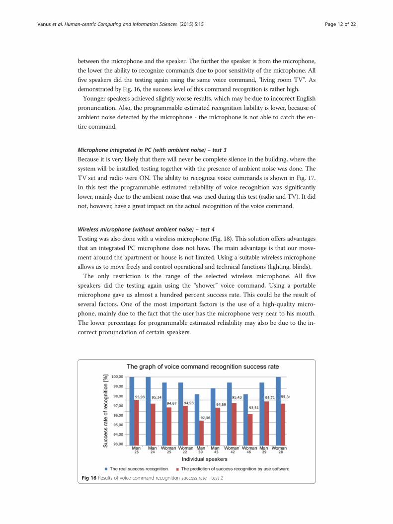
Microphone integrated in PC (distance 3 m, without ambient noise) – test 2
Similarly, further testing was done but the microphone distance from the PC was approxi-
mately 3 m. The level of success of voice recognition commands depends on the distance
Fig 15 Results of voice command recognition success rate - test 1
Vanus et al. Human-centric Computing and Information Sciences (2015) 5:15 Page 12 of 22
between the microphone and the speaker. The further the speaker is from the microphone,
the lower the ability to recognize commands due to poor sensitivity of the microphone. All
five speakers did the testing again using the same voice command, “living room TV”. As
demonstrated by Fig. 16, the success level of this command recognition is rather high.
Younger speakers achieved slightly worse results, which may be due to incorrect English
pronunciation. Also, the programmable estimated recognition liability is lower, because of
ambient noise detected by the microphone - the microphone is not able to catch the en-
tire command.
Microphone integrated in PC (with ambient noise) – test 3
Because it is very likely that there will never be complete silence in the building, where the
system will be installed, testing together with the presence of ambient noise was done. The
TV set and radio were ON. The ability to recognize voice commands is shown in Fig. 17.
In this test the programmable estimated reliability of voice recognition was significantly
lower, mainly due to the ambient noise that was used during this test (radio and TV). It did
not, however, have a great impact on the actual recognition of the voice command.
Wireless microphone (without ambient noise) – test 4
Testing was also done with a wireless microphone (Fig. 18). This solution offers advantages
that an integrated PC microphone does not have. The main advantage is that our move-
ment around the apartment or house is not limited. Using a suitable wireless microphone
allows us to move freely and control operational and technical functions (lighting, blinds).
The only restriction is the range of the selected wireless microphone. All five
speakers did the testing again using the “shower” voice command. Using a portable
microphone gave us almost a hundred percent success rate. This could be the result of
several factors. One of the most important factors is the use of a high-quality micro-
phone, mainly due to the fact that the user has the microphone very near to his mouth.
The lower percentage for programmable estimated reliability may also be due to the in-
correct pronunciation of certain speakers.
Fig 16 Results of voice command recognition success rate - test 2

Fig 17 Results of voice command recognition success rate - test 3
Vanus et al. Human-centric Computing and Information Sciences (2015) 5:15 Page 13 of 22
Wireless microphone (with ambient noise) – test 5
Because the user will more freely around the building, it is likely that there will be interfer-
ence/ambient noise (Fig. 19). For example, when a TV set is on or when other residents are
talking to each other. The advantage of a wireless microphone is that the user has the micro-
phone almost always very near to his mouth and thereby eliminates most disturbing noises,
because the microphone captures the voice command right from the speaker’s mouth.
Even in this case, the success rate of voice command recognition is very high despite
the fact that testing was done with the presence of ambient noise. This is mainly due to
the use of a high-quality microphone and due to the fact that the speakers were very
close to the microphone.
Suppression of additive background noise for voice control over operating and technical
functions in the smart home care
Implemented application of voice communication with the control system was supplied
with a sophisticated system for filtering the additive background noise from the real
Fig 18 Results of voice command recognition success rate - test 4
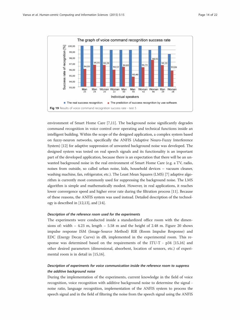
Fig 19 Results of voice command recognition success rate - test 5
Vanus et al. Human-centric Computing and Information Sciences (2015) 5:15 Page 14 of 22
environment of Smart Home Care [7,11]. The background noise significantly degrades
command recognition in voice control over operating and technical functions inside an
intelligent building. Within the scope of the designed application, a complex system based
on fuzzy-neuron networks, specifically the ANFIS (Adaptive Neuro-Fuzzy Interference
System) [12] for adaptive suppression of unwanted background noise was developed. The
designed system was tested on real speech signals and its functionality is an important
part of the developed application, because there is an expectation that there will be an un-
wanted background noise in the real environment of Smart Home Care (e.g. a TV, radio,
noises from outside, so called urban noise, kids, household devices – vacuum cleaner,
washing machine, fan, refrigerator, etc.). The Least Mean Squares (LMS) [7] adaptive algo-
rithm is currently most commonly used for suppressing the background noise. The LMS
algorithm is simple and mathematically modest. However, in real applications, it reaches
lower convergence speed and higher error rate during the filtration process [11]. Because
of these reasons, the ANFIS system was used instead. Detailed description of the technol-
ogy is described in [12,13], and [14].
Description of the reference room used for the experiments
The experiments were conducted inside a standardized office room with the dimen-
sions of: width – 4.23 m, length – 5.58 m and the height of 2.48 m. Figure 20 shows
impulse response ISM (Image-Source Method) RIR (Room Impulse Response) and
EDC (Energy Decay Curve) in dB, implemented in the experimental room. This re-
sponse was determined based on the requirements of the ITU-T - p34 [15,16] and
other desired parameters (dimensional, absorbent, location of sensors, etc.) of experi-
mental room is in detail in [15,16].
Description of experiments for voice communication inside the reference room to suppress
the additive background noise
During the implementation of the experiments, current knowledge in the field of voice
recognition, voice recognition with additive background noise to determine the signal -
noise ratio, language recognition, implementation of the ANFIS system to process the
speech signal and in the field of filtering the noise from the speech signal using the ANFIS

Fig 20 Compares result’s from ISM and fast-ISM
Vanus et al. Human-centric Computing and Information Sciences (2015) 5:15 Page 15 of 22
system, was used. For the quality evaluation of the processing of speech signal picked up
on the output of the filter with the LMS algorithm, the DTW criterion was used. For
reaching the designated goal, a simulation model of the ANFIS system with an application
for filtering the additive noise of the speech signal was used. A numerical simulation of
the ANFIS system model with verifying of the influence of individual parameter settings
on its behavior was also conducted inside the MATLAB. A method for setting the optimal
parameters of the adaptive filter with the LMS algorithm was then designed.
The human voice is the first source signal (commands) x(n), (Fig. 21). To carry out
the experiments, a test voice by the ITU-T P was used. 501 [−] (Test Signals for Use in
Tele phonometry). The second source signal is the background noise n(n). This noise
can be adjusted within the range of 0 – 100 dB and it synthesizes the standard noises,
which can occur (TV, Hi-Fi, tuner, fan, etc.). These source signals are reproduced by
the primary and reference speakers (Fig. 21).
The designed system consists of two inputs (primary and reference microphone). The
first input is the reference microphone, which picks up the unwanted noise. This signal
is marked as n1(n), (Fig. 21). The second input is the primary microphone (measured
signal) which picks up the usable signal (voice - commands) plus unwanted background
Fig 21 Simplified fundamental scheme of the implemented system for filtering the additive backgroundnoise out of the voice control of operating and technical functions inside an intelligent building

Vanus et al. Human-centric Computing and Information Sciences (2015) 5:15 Page 16 of 22
noise, this signal is marked as m(n). Detailed description of the designed system is in
[12,13], and [14].
Different networks (structures) of the ANFIS were examined during the conducted
experiments. Overview of the used ANFIS network structure model and comparison of
parameters can be found in Table 1.
Figures 22, 23 and 24 show the results of conducted experiments. Fig. 22 (a-f ) com-
pares different timelines of examined signals. A high SNR = 80 dB was used for the ex-
periments, so the interfering signal completely contaminated usable speech. On such
guaranteed signals, the effectiveness of the proposed method is demented.
Figure 23 (a-c) shows 3D spectrograms of examined signals. A 3D spectrogram is a
form of spectrogram that is displayed in three dimensions. Compared to the classic
spectrogram, the intensity of respective frequencies is displayed on the Z-axis. If a sec-
tional plane parallel to the frequency axis and the Z-axis of the 3D spectrogram was
done at a certain time, a spectrum of signals in the respective time would be the result.
Figure 24 (a-f ) shows spectrograms of analysed speech signals. It is a 3D graph, which
has two individually variable axes - frequency and time (the order of section spectres).
A 2D spectrogram is used here; it is a top view on the original 3D graph.
Description of the methods for evaluating the quality of filtering the additive noise out of
the speech signal
In the experiments performed, the SSNR (Segmental Signal to Noise Ratio) value of the
contaminated speech signal and the signal after passing the system designed was deter-
mined. The difference between these values showed what improvement was achieved
by each model. The SSNR ratio is defined by the following relation [17]:
SSNR ¼ 1K
XL−1i¼0
10 log
XM−1
n¼0
x2i nð Þ
XM−1
n¼0
n2i nð Þ
0BBBB@
1CCCCA
|fflfflfflfflfflfflfflfflfflfflfflfflfflfflfflffl{zfflfflfflfflfflfflfflfflfflfflfflfflfflfflfflffl}SNRi
⋅VADi; ð1Þ
where L is the number of segments of speech signal,
K is the number of segments in speech activity,
VADi is information about speech activity (values zero and one), further xi(n) = x(mi + n),
ni(n) = n(mi + n) – segments of lengthM selected step m,
SNRi is Local SNR (Signal to Noise Ratio).
Table 1 Information about ANFIS Structures Used
ANFIS information
Building the ANFIS Model A B C D
Number of Nodes (NN) 21 35 53 75
Number of Linear Parameters (NLP) 12 27 48 75
Number of Nonlinear Parameters (NNP) 12 18 24 30
Total Number of Parameters (TNP) 24 45 72 105
Number of Fuzzy Rules (NFR) 4 9 16 25
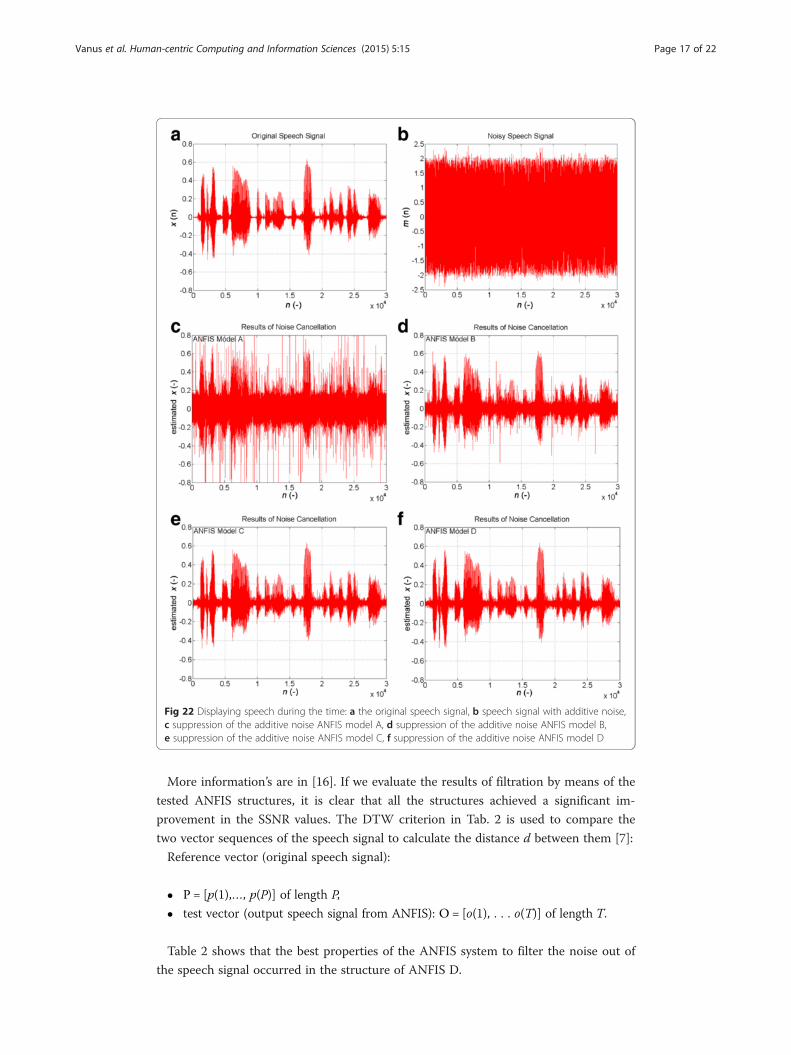
Fig 22 Displaying speech during the time: a the original speech signal, b speech signal with additive noise,c suppression of the additive noise ANFIS model A, d suppression of the additive noise ANFIS model B,e suppression of the additive noise ANFIS model C, f suppression of the additive noise ANFIS model D
Vanus et al. Human-centric Computing and Information Sciences (2015) 5:15 Page 17 of 22
More information’s are in [16]. If we evaluate the results of filtration by means of the
tested ANFIS structures, it is clear that all the structures achieved a significant im-
provement in the SSNR values. The DTW criterion in Tab. 2 is used to compare the
two vector sequences of the speech signal to calculate the distance d between them [7]:
Reference vector (original speech signal):
� P = [p(1),…, p(P)] of length P,
� test vector (output speech signal from ANFIS): O = [o(1), . . . o(T)] of length T.
Table 2 shows that the best properties of the ANFIS system to filter the noise out of
the speech signal occurred in the structure of ANFIS D.

Fig 23 3D spectrograms of analysed signals: a the original speech signal, b speech signal with additivenoise, c suppression of additive noise ANFIS model B
Vanus et al. Human-centric Computing and Information Sciences (2015) 5:15 Page 18 of 22
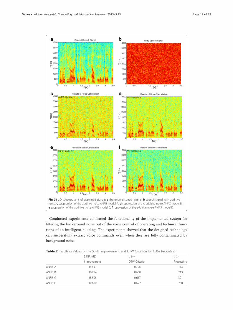
Fig 24 2D spectrograms of examined signals: a the original speech signal, b speech signal with additivenoise, c suppression of the additive noise ANFIS model A, d suppression of the additive noise ANFIS model B,e suppression of the additive noise ANFIS model C, f suppression of the additive noise ANFIS model D
Vanus et al. Human-centric Computing and Information Sciences (2015) 5:15 Page 19 of 22
Conducted experiments confirmed the functionality of the implemented system for
filtering the background noise out of the voice control of operating and technical func-
tions of an intelligent building. The experiments showed that the designed technology
can successfully extract voice commands even when they are fully contaminated by
background noise.
Table 2 Resulting Values of the SSNR Improvement and DTW Criterion for 180-s Recording
SSNR (dB) d (−) t (s)
Improvement DTW Criterion Processing
ANFIS A 15.551 0.725 113
ANFIS B 16.754 0.630 213
ANFIS C 18.598 0.617 391
ANFIS D 19.689 0.692 768
Vanus et al. Human-centric Computing and Information Sciences (2015) 5:15 Page 20 of 22
DiscussionThe aim of this work was to develop, implement and test voice control of operational
and technical functions in a smart building. The final implementation was performed
on a simulation model of a smart apartment. This model is able to simulate control of
lighting, sun-blinds and air conditioning. Another task was to design a connection of
the voice recognition system to the KNX bus and connection of the smart building
simulation model. After performing an analysis of available and usable voice recogni-
tion systems, a set of criteria was established in order to enable the final implementa-
tion of the created system. The main criterion for the selection of the final solution was
the price of the application. Use of the Microsoft SAPI module is free in the English
version of the Windows system, however, an application to communicate with the
KNX bus system on the user side and on the other side had to be created.
A voice synthesis feature was implemented in the application. The final application is
able to recognize not only the user’s voice commands, but the application may also answer
back. In order to test the functionality of the entire work, a statistics module was added to
the application. To improve user comfort, a settings menu was added which enables the
user to adjust the basic properties of the synthesis and voice recognition modules.
The next step in the development was the actual start-up and programming of the
Smart Home Care simulation model. ETS software was used to program the KNX tech-
nology. Functionality was demonstrated by controlling lights and blinds. After the
Smart Home Care module was successfully programmed, communication between this
model and the created application was tested. A KNX/IP router was used to create
communication between the KNX network and the personal computer. The advantage
of this solution, as opposed to using a USB bus, is that it would be theoretically pos-
sible to connect/insert a Wi-Fi router between the KNX/IP router and the computer,
and communicate with the entire network wirelessly. Communication was done via the
Ethernet. The application was additionally programmed with a UDP client and a KNX/
IP router was integrated into the Smart Home Care simulation model. The Wire Shark
program was used to obtain communication addresses, ports and to transmit messages.
The most difficult part was the actual creation of the voice recognition application and
establishing communication with the KNX bus. The designed and implemented solu-
tion works according to the requirements. The indisputable advantage is zero cost, pro-
vided that the user is running Windows Vista (or higher) in the English version. As
evident from the success achieved by the proposed voice recognition communication
method, the voice recognition feature works very well. Ten people participated in the
testing. Each person conducted five tests and uttered 100 voice commands. The average
success rate of real voice recognition based on all tests is approximately 98.78 % (note
that interference, noise or greater distance between the speaker and the microphone
were used during certain tests). Some minor errors occasionally occurred when the ap-
plication was in idle mode (waiting for the activation phrase) and a conversation in
Czech language was taking place in the room. This problem is eliminated by adding a
restrictive conditions to the program, which accepts the initiation phrase if the applica-
tion is at least 90 % sure that the phrase was correctly received/said. Despite this, the
program may sometimes recognize a Czech word as the actual initiation phrase. As a
possible improvement - when used in the real world, it is advisable to use a micro-
phone network covering the entire area of the building.
Vanus et al. Human-centric Computing and Information Sciences (2015) 5:15 Page 21 of 22
ConclusionsThe article describes the draft and the implementation process of the voice control of
operating and technical functions inside an intelligent building with assistive care for
seniors (Smart Home Care) within a real environment with additive noise. This work
and its implementation has been divided into five main parts: programming and start-
ing the simulation panel of Smart Home Care with the KNX technology, implementa-
tion of communication between the tool created for voice control and the Smart Home
Care simulation panel, programming a software application for voice control of operat-
ing and technical functions inside an intelligent building, conducting a statistic examin-
ation of the created software application’s speech recognition and implementation of a
sophisticated tool for filtering the noise out of speech. This article represents a complex
solution to voice control of operating and technical functions of the Smart Home Care.
Competing interestsThe authors declare that they have no competing interests.
Authors’ contributionsAll authors contributed to the content of this paper. All authors read and approved the final manuscript.
AcknowledgementsThis paper has been elaborated in the framework of the project Opportunity for young researchers, reg. no. CZ.1.07/2.3.00/30.0016, supported by Operational Programme Education for Competitiveness and co-financed by the EuropeanSocial Fund and the state budget of the Czech Republic. This work is partially supported by the Science and ResearchFund 2014 of the Moravia-Silesian Region, Czech Republic. This research was supported in part by VSB-TechnicalUniversity Ostrava, FEECS under the project SGS registration number SP 2015/181, SP 2015/154.
Received: 29 September 2014 Accepted: 1 June 2015
References
1. Merz H, Hansenmann T, Hubener C (2008) Automatizované systémy budov: Sdělovací systémy KNX/EIB, LON aBACnet. 2008. vyd. Grada Publishing, a.s, Praha, 978-80-247-2367-92. Vanus J, Koziorek J, Hercik R (2013) Design of a smart building control with view to the senior citizens’ needs.
In: ‘Book Design of a smart building control with view to the senior citizens’ needs’, 1st edn., pp 422–4273. Park KH, Bien Z, Lee JJ, Kim BK, Lim JT, Kim JO, Lee WJ (2007) Robotic smart house to assist people with
movement disabilities. Autonomous Robots 22(2):183–1984. Hsu CL, and Chen KY (2009) Practical design of intelligent remote-controller with speech-recognition and self-
learning function. In Machine Learning and Cybernetics, 2009 International Conference on (Vol. 6, pp. 3361–3368).IEEE. (2009, July).
5. Soda S, Nakamura M, Matsumoto S, Izumi S, Kawaguchi H, and Yoshimoto M (2012) Implementing virtual agent asan interface for smart home voice control. In Software Engineering Conference (APSEC), 2012 19th Asia-Pacific(Vol. 1, pp. 342–345). IEEE. (2012, December).
6. Verma P, Singh R, Singh AK (2013) A framework to integrate speech based interface for blind web users on thewebsites of public interest. Human-centric Computing and Information Sciences 3:21, doi:10.1186/2192-1962-3-21
7. Vanus J, Styskala V (2011) Application of variations of the LMS adaptive filter for voice communications withcontrol system. Tehnički vjesnik – Technical Gazette 18(4):553–560
8. Martinek R, Al-Wohaishi M, and Zidek J (2010) Software based flexible measuring systems for analysis of digitallymodulated systems. In Roedunet International Conference (RoEduNet), 2010 9th (pp. 397–402). IEEE. (2010, June).
9. Vanus J, Koziorek J, Hercik R (2013) The design of the voice communication in smart home care. InTelecommunications and Signal Processing (TSP), 2013 36th International Conference on (pp. 561–564).IEEE. (2013, July).
10. Luo Y, Hoeber O, Chen Y (2013) Enhancing Wi-Fi fingerprinting for indoor positioning using human-centriccollaborative feedback. Human-centric Computing and Information Sciences 3:2, doi:10.1186/2192-1962-3-2
11. Martinek R, Zidek J (2010) Use of Adaptive Filtering for Noise Reduction in Communication systems. InConference Proceeding: The International Conference Applied Electronics (AE). Pilsen, Czech Republic, 8–9September 2010, pp. 215–220, ISBN 978-80-7043-865-7, ISSN 1803–7332, INSPEC Accession Number: 11579482.
12. Martinek R, Zidek J (2014) The Real Implementation of ANFIS Channel Equalizer on the System of Software-Defined Radio. In: IETE Journal of Research, vol 60. Taylor & Francis, London, UK, Issue 2, pages 183–193, ISSN0377–2063 (Print), 0974-780X (Online), doi:10.1080/03772063.2014.914698
13. Martinek R, Manas J, Zidek J, Bilik P (2013) Power Quality Improvement by Shunt Active Performance FiltersEmulated by Artificial Intelligence Techniques. In Conference Proceedings: 2nd International Conference onAdvances in Computer Science and Engineering (CSE 2013). Los Angeles, CA, USA, July 1–2, 2013, pp. 157–161,ISSN 1951–6851, ISBN 978-90786-77-70-3, doi:10.2991/cse.2013.37.
Vanus et al. Human-centric Computing and Information Sciences (2015) 5:15 Page 22 of 22
14. Martinek R, Zidek J (2012) Refining the diagnostic quality of the abdominal fetal electrocardiogram using thetechniques of artificial intelligence. In Journal: Przeglad Elektrotchniczny (Electrical Review), Volume 88, Issue 12B,Warszawa, Poland, pp. 155–160, ISSN 0033–2097.
15. ITU-T Test Signals for Telecommunication Systems, ITU-T P. 501, web. http://www.itu.int/net/itu-t/sigdb/genaudio/Pseries.htm.
16. ITU-T Recommendation P.34 was revised by the ITU-T Study Group XII (1988–1993) and was approved by theWTSC (Helsinki, March 1–12, 1993), web. http://www.itu.int/ITU-T/recommendations/rec.aspx?rec=1726&lang=en.
17. Vonasek M, Pollak P (2005) Methods for Speech SNR Estimation: Evaluation Tool and Analysis of VAD Dependency.Radioengineering 14(1):6–11, ISSN 1210–2512. (2005)
Submit your manuscript to a journal and benefi t from:
7 Convenient online submission
7 Rigorous peer review
7 Immediate publication on acceptance
7 Open access: articles freely available online
7 High visibility within the fi eld
7 Retaining the copyright to your article
Submit your next manuscript at 7 springeropen.com