tests of a spinning 105 mm artillery shell · pdf filead-a084 230 weapons systems research lab...
TRANSCRIPT

AD-A084 230 WEAPONS SYSTEMS RESEARCH LAB ADELAIDE (AUSTRALIA) F/S 20/4iI TWJNL TESTS OF A SPINNING 105 MM ARTILLERY SHELL MODL WI--ETCCU)
U N E 9 C JERREY
CLASSIFEED WRL-0122-TR NL
"UlllllEhhh hihE,/Iml/I/I/I/I//IE hll hlllll

111 1. 4 11_8 125
li11111.5 -4 I
MW.RoCOrIY R( ,OIltlIloN II SI C HART
N' I 4,A ,W lI T N ,

WSRL-01 22-TR ARl-CWl00
DEPARTMENT OF DEFENCEDEFENCE SCIENCE AND TECHNOLOGY ORGANISATION
WEAPONS SYSTEMS RESEARCH LABORATORY
DEFENCE RESEARCH CENTRE SALISBURY
00 SOUTH AUSTRALIA
TECHNICAL REPORTWSRL-0122-TR
WIND TUNNEL TESTS OF A SPINNING 105 mm ARTILLERY SHELLMODEL WITH CANARD CONTROL SURFACES
C.JERMEY
1.7 -iE : I~T ED $TATZS AY
IS AjHCj!,. TO
REPROD~uCE AND1 SELL 'THIS REPORT
-~ DTICSMAY 19 1980
Appoved for Public Reee0
, wCOPY No. 3oSEPTEMBER 1979
L 80 ;5 ;~031.

Acoession Mar
NTIS Q1.4-1 UNCLASSIFIEDW~C TAB
UUaonouned AR-001-908____t__i______ DEPARTMENT OF DEFENCE
y ,EFENCE SCIENCE AND TECHNOLOGY ORGANISATIONDistributlonL
Aistlbi ity~odWEAPONS SYSTEMS RESEARCH LABORATORYSAvellabil1ityCodes
Avail aiid/or PnDist special
WSRL- 122-TR
SIND5UNNEL JSTS OF A SPINNING nn.4RTILLERY SHELL
c t .. MODEL WITH CANARD CONTROL SURFACES . .
-C.fJermey
SUMMARY
Tests have been conducted to measure the aerodynamic
characteristics of a spinning model of a 105 mm shell fittedwith canard control surfaces. The tests covered an
incidence range of -2° to 150, a Mach number range of 0.70
to 0.95, and a control deflection range of zero to 30 .
The effectiveness of the canards as pitch and yaw controlsand for generating manoeuvring forces is discussed.
The conclusion is reached that available manoeuvring forceswould be small, and an example is given for a typical
trajectory in which a maximum shift of 90 m from the un-
guided impact point could be obtained.
DTICSELECTE1
MAY 19 1980M
Approved for Public Release D
POSTAL ADDRESS: Chief Superintendent, Weapons Systems Research Laboratory,
Box 2151, G.P.O., Adelaide, South Australia, 5001.
UNCLASSIFIED
.,,

IXiOCUMI-NT' CONTROL DLK A SI i l'I-T
Security clasiification of this pape FUNCLASSIFIED---
I DOCEUMENT NUMBERS 2 FSECURITY CLASSIFICATION
AR a. CompleteNumber: AR-001-908 Document: Unclassified
Reportb. Title inNumber: WSRL-0122-TR Isolation: Unclassified
Other c. Summary inNumbers: Isolation: Unclassified
3[TE
WIND TUNNEL TESTS OF A SPINNING 105 mmARTILLERY SHELL MODELWITH CANARD CONTROL SURFACES
4 FPERSONAL AUTHOR(S): 5 rDOCUMENT DATE:
C. Jermey F September 1979
OF PAGES 40
7 r7.1 CORPORATE AUTHOR(S): 8 REFERENCE NUMBERS
Weapons Systems Research Laboratory a.Ts: DT7/3
b. Sponsoring____ ___ ____ ___ ___ ____ ___ ____ ___ _ Aency:
7.2 DOCUMENT SERIESAND NUMBER / 9 COST CODE:
Weapons Systems Research Laboratory01 22-TR 330834
to 'IMPRINT (Publishing organisation) II COMPUTER PROGRAM(S)r!j(Title(s) and language(s))
Defence Research Centre Salisbury
121 RELEASE UIMITATIONS (of the document):
Approved for Public Release
12.0 1OVERSEAS I N7 AT--[]7 [F7 [-7] [ 7 E
Security classification of this page: UNCLASSIFIED

Security classification of this page: UNCLASSIFIED
13 IANNOUNCEMENT UMITATIONS (of the information on these pages):
No limitation
14 [ DESCRIPTORS: 105 mm shells I5 COSATI CODES:
a. EJC Thesaurus Projectiles
Terms Spinning projectilesSpin stabilised ammunitionWind tunnel testsCanard controls
b. Non-ThesaurusTerms
16 FULBRARY LOCATION CODES (for libraries listed in the dsrbto)
17 SUMMARY OR ABSTRACT:(if this is security classified, the announcement of this report will be similarly classified)
Tests have been conducted to measure the aerodynamic characteristicsof a spinning model of a 105 mm shell fitted with canard controlsurfaces. The tests covered an incidence range of -" to 15 , a Machnu~er range of 0.70 to 0.95, and a control deflection range of zero to30, . The effectiveness of the canards as pitch and yaw controls andfor generating manoeuvring forces is discussed. The conclusion isreached that available manoeuvring forces would be small, and an
; example is given for a typical trajectory in which a maximum shiftof 90 m from the unguided impact point could be obtained.
Sf
Security clififcation of this page: [ UNCLASSIFIED

WSRL-0122-TR
TABLE OF CONTENTS
Page No.
1. INTRODUCTION 1
2. EXPERIMENTAL DETAILS 1 - 2
2.1 Model and balance 1
2.2 Experimental procedure 1
2.3 Accuracy of results 2
3. PRESENTATION AND DISCUSSION OF RESULTS 2 - S
3.1 Effects of canards and spin rate 2 - 3
3.2 Effects of pitch canard deflection 3
3.3 Effects of yaw canard deflection 3
3.4 Combined effects of pitch and yaw canard deflections 3 - 4
3.5 Combined effects of spin rate with pitch and yaw 4canard deflections
3.6 Trim incidence and manoeuvring forces at trim 4
3.7 Concluding remarks 4 - S
NOTATION 6
REFERENCES 7
LIST OF FIGURES
1. 105 mm canard controlled shell model, showing internal details
2. Assembly of model, balance and balance shield
3. Axis system used in presentation of results
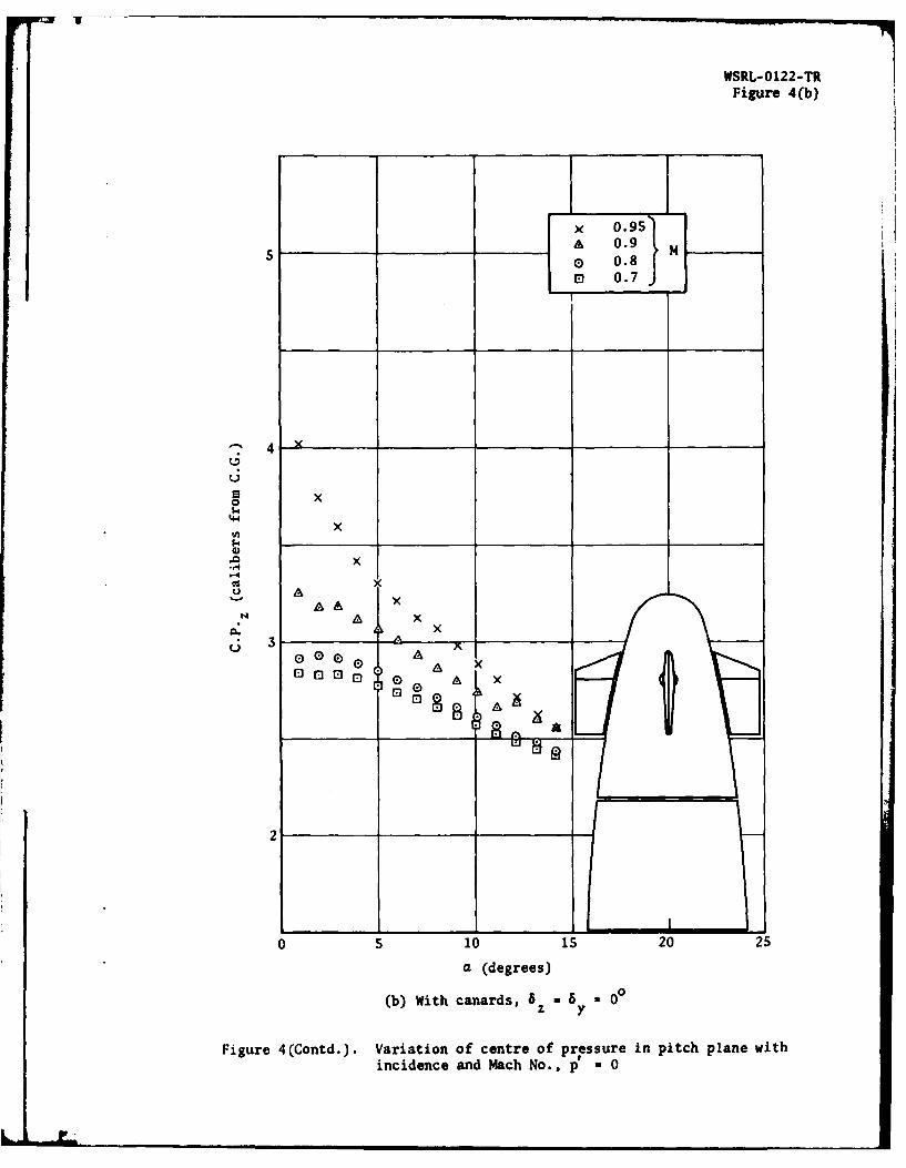
4. Variation of centre of pressure in pitch plane with incidenceand Mach No., p' = 0
5. Variation of normal force coefficient with incidence and Mach No., p' 0
6. Variation of pitching moment coefficient with incidence andMach No., p' 0 0
7. Variation of side force coefficient with incidence, Mach No. and spin rate
8. Variation of yawing moment coefficient with incidence, Mach No. and spinrate
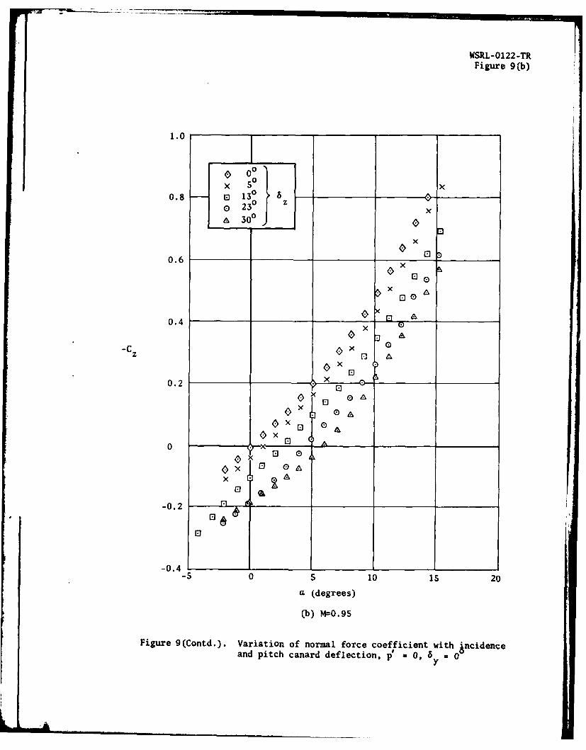
9. Variation of normal force coefficient with incidence and pitch canarddeflection, p' = 0, by = 00
10. Variation of pitching moment coefficient with incidence and pitch canarddeflection, p = O, a 8 i 00
11. Variation of side force coefficient with incidence and yaw canarddeflection, p' - 0, 8 = 00
z

WSRL-0122-TR
12. Variation of yawing moment coefficient with incidence and yaw canarddeflection, p = 0, 5 = 00
z
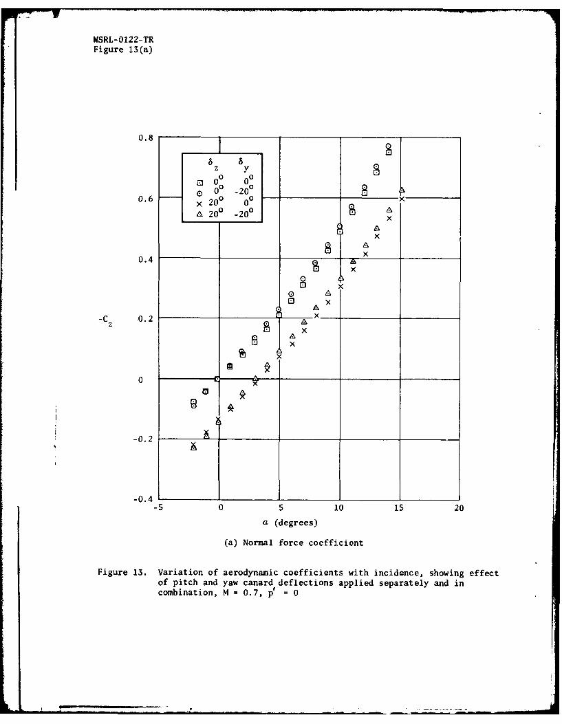
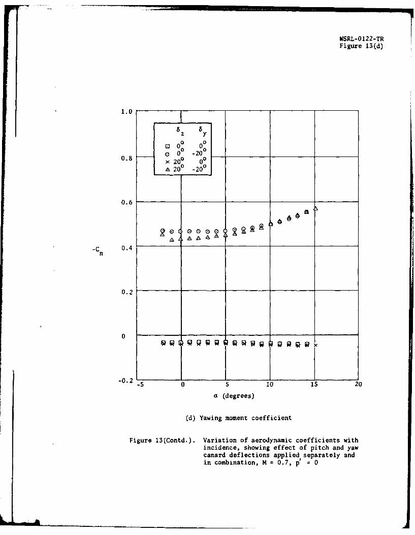
13. Variation of aerodynamic coefficients with incidence, showing effectof pitch and yaw canard deflections applied separately and incombination, M = 0.7, p'= 0
14. Variation of aerodynamic coefficients with spin rat8 , showing effectof pitch and yaw canard deflections, M = 0.7, a = 5
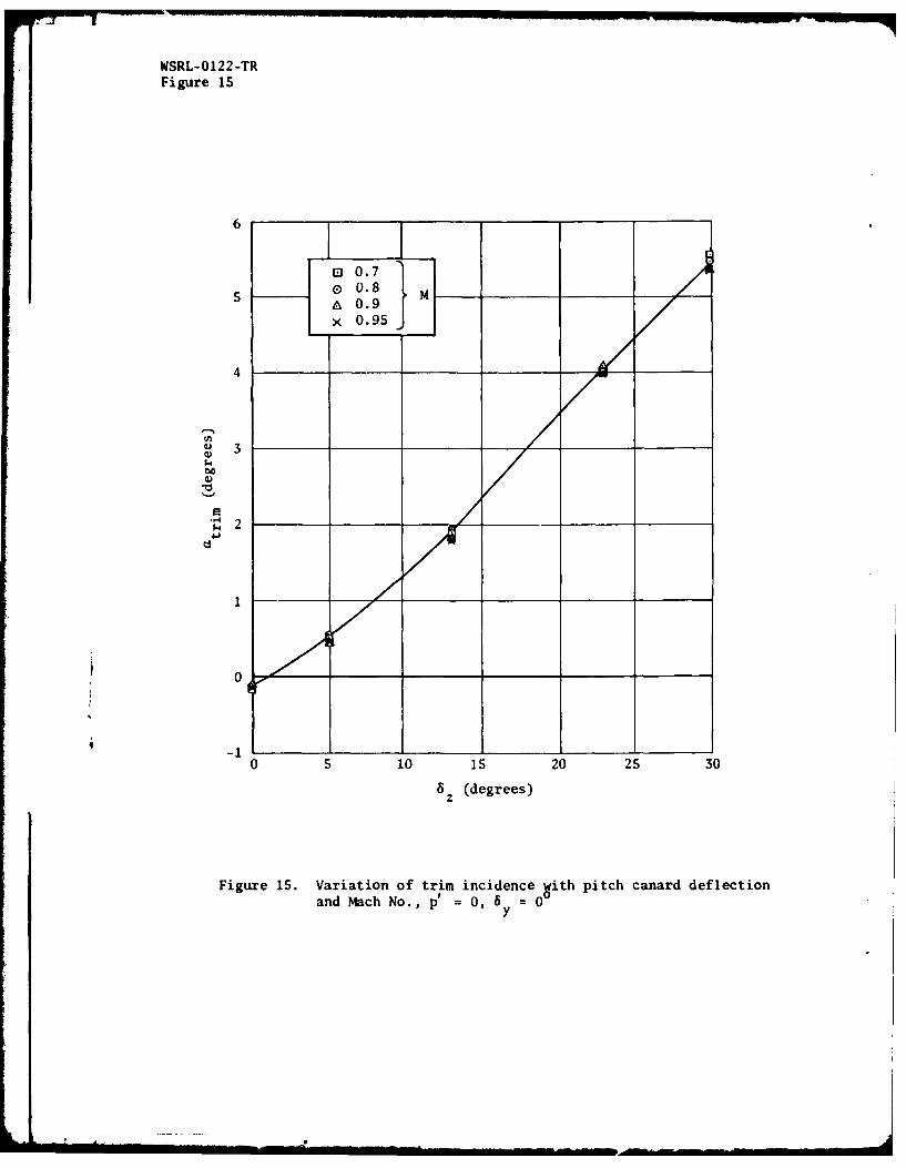
15. Variation of trim incidence with pitch canard deflection andMach No., p' = 0, 8 = 0°
Y
16. Variation of normal force and side force coefficients with trimincidence and Mach No.

- 1 = WSRL-0122-TR
1. INTRODUCTION
The work reported here was carried out during February 1978 as part of aprogramme to assess the effectiveness of canard surfaces in controlling the flightpath of a spin stabilised projectile. The baseline projectile shape chosen forinvestigation was the 105 mm M1 artillery shell, and an earlier series of windtunnel tests conducted on this standard shape are reported by Jermey inreference 1. The tests reported here used, as far as possible, the same model,systems and techniques as already detailed in reference 1. Therefore, exceptwhere significant differences existed, detailed description of the model, drivesystem and experimental techniques are not included in this report. Atheoretical study of the effectiveness of canard controls on the 105 mm shell hasalso been conducted by Brown, Hunter and Lloyd and is reported by them inreference 2. Conclusions from both references 1 and 2 suggest that canardsurfaces do not appear to offer very high manoeuvrability in subsonic andtransonic flight; in particular, Brown et al estimate a flight path deviationof approximately 80 m for a manoeuvring phase lasting 16 s at Mach 0.75. Thepresent experimental work generally confirms this conclusion. For the parametersgiven above (16 s manoeuvre at Mach 0.75) the experimental data give a maximumflight path deviation of approximately 90 m.
2. EXPERIMENTAL DETAILS
2.1 Model and balance
The basic model was the half scale 105 mm HE Ml shell model built for theearlier test series(ref.1). To assess the canard effectiveness in a realis-tic way the nose of the shell was redesigned to conform with the controlsection geometry then under consideration. Figures 1 and 2 show the modeland balance assembly, and it can be seen that the nose section is somewhatblunter and more bulbous than that of the standard shell. The modificationsconsist of the removal of the standard fuse and the addition of two separatepieces, a non-spinning control section which contains the two canard pairs,and a thin walled shell which fairs the control section back into the bodyand which spins with the shell body.
The control section is mounted on a shaft which passes through the hollowcore of the air motor and keys into the model support sting to preventrotation. Lateral support is provided by ball bearings between the shaftand the shell body. For a more detailed description of the model supportand drive system the reader is referred to reference 1.
2.2 Experimental procedure
All tests were conducted in the 360 mm x 380 mm slotted working section ofthe continuous flow wind tunnel S-1 at the Aeroballistics Division of WSRL.Four component data (no drag or rolling moment) were obtained for a Machnumber range of 0.70 to 0.95, an incidence range of -2° to 150, and forcontrol deflections from 0° to 300. No supersonic runs were conducted asthe terminal speed of the shell is subsonic for all trajectories in whichterminal guidance could be employed. A Reynolds number of Rd = 3.9 x l0
(based on maximum body diameter) was used for all tests, which compares withflight Reynolds numbers of 1.0 to 2.0 x 10⁶. To simulate the flow cond-itions expected at the higher Reynolds numbers of the full scale shell, aboundary layer trip, shown in figure 1, was used to ensure a turbulent bound-ary layer over the shell body.
For further details of the conduct of the individual wind tunnel teststhe reader is referred to reference 1.

NSRL-0122-TR = 2 -
2.3 Accuracy of results
Reference 1 discusses most of the sources of error in the present results,so those item- which are common to both reference 1 and the present work aresimply identified below and the accuracy applicable to each is given. Thesetting of control surface deflections is the only feature not present inreference 1, and so this is discussed in some detail.
(a) Force and moment coefficients: ± 0.01, ± 1%
(b) Mach number: ± 0.01
(c) Reynolds number: all tests within range (3.9 ± 0.1) x 10
(d) Incidence: ± 0.20
(e) Roll rate: for each data point ± 6 rad/s
for an entire incidence traverse ± 19 rad/s
(f) Control deflections:
The angular deflection of each canard was set by driving the modelto a predetermined attitude and then setting the canard top rearsurface level by the use of a dial indicator referenced to the bottomtunnel liner. Each canard was individually set and then locked inposition prior to each series of runs, the canard angular deflectionbeing given by the model pitch angle plus the half angle of the canardrear surface (1 °). Uncertainties arising in this setting techniqueinclude the model attitude (readout errors and sting bending due totare effects), inclination of the tunnel liner surface, and dimensionaluncertainty of the individual canards. Nominal accuracy for thesetting of each canard was 0.10, and the cumulative effect of theremaining errors amounts to an additional 0.150, so an uncertainty of
0.25 can be assumed for each given deflection.
3. PRESENTATION AND DISCUSSION OF RESULTS
All results are referred to the axis system shown in figure 3, the origin ofthe system being located at the nominal centre of gravity of the standard shell.Only graphical results are presented, data having been selected to illustratethe aerodynamic aspects of interest. A tabulation of the complete aerodynamicdata is available, however, and may be obtained on request to the author.
3.1 Effects of canards and spin rate
Figures 4, 5 and 6 show respectively, the centre of pressure, normal forceand pitching moment coefficients versus incidence for the model both with andwithout the canards attached. These results are given only for zero spinrate since their variation with spin rate is small. The centre of pressurewithout canards is further forward than for the standard shell (attributableto the longer and blunter nose shape) and shows the normal effect of forwardmovement with increasing Mach number and rearward movement with increasingincidence. The addition of the canards, with their lift contributionoccurring at a relatively constant position, stabilises the centre of pressuresomewhat, reducing its variability with Mach number and incidence. Normalforce coefficients without canards (figure 5(a)) are very similar to thoseof the standard shell shape. The addition of canards (figure 5(b)) increasesnormal force coefficients by approximately 50% throughout the Mach numberand incidence range. Pitching moment coefficients (figure 6) follow thesame pattern, except that the model without canards is more unstable thanthe standard shell shape due to the further forward centre of pressure.The addition of canards further destabilises the model, moments on thecanard equipped model being approximately 70% greater than those on thestandard shell shape.

- 3 - WSRL-0122-TR
Figures 7 and 8 show the side force and yawing moment coefficients versusincidence with and without canards, plus the effect of varying spin rate(given in non-dimensional form). All data show a zero shift, small for themodel with no canards, and greater for the canard equipped case. This ismost likely due mainly to non-axial airflow in the tunnel working sectionand possibly also to small errors in the setting of the canards. As aresult, absolute values of coefficients may be significantly in error(although within the limits as given in Section 2.3) but trends with incidenceand roll rate should be reliable. Once again, results for the model with nocanards agree closely with earlier results from the standard shell shape.The addition of canards generally has very little effect in the low incidence(up to 100) range, but appears to produce a small to moderate increase inMagnus forces and moments at higher incidences.
3.2 Effects of pitch canard deflection
Pitch canard deflections ranged from 00 up to 300, and their effect onnormal force and pitching moment coefficients is shown in figures 9 and 10.The two unusual deflection angles, 130 and 230, were the unfortunate resultof a 30 setting error present when setting to nominal angles of 100 and 200.The error was discovered during the test series, but too late to conductrepeat runs at the originally intended angles. Results are plotted only forzero spin rate and two Mach numbers, 0.7 and 0.95, since the variation withspin rate and Mach number is small. Figures 9 and 10 show that normal forceand pitching moments vary relatively linearly throughout the incidence rangefor pitch canard deflections of up to 230. The curves for 300 deflectionindicate that stalling of the canard surfaces commences at a canard to freestream incidence of approximately 250 (i.e., in this case, at S0 bodyincidence) and worsens progressively for higher canard to freestream angles.Pitching moment curves show that trim angles of up So S 0 (spin-stabilised)can be obtained with canard deflections of up to 30 . A more detaileddiscussion of trim angles and normal force available at trim is given inSection 3.6.
3.3 Effects of yaw canard deflection
Yaw canard deflections ranged from 00 to 309, and their effect on sideforce and yawing moment coefficients is shown in figures 11 and 12. Plottedresults are given only for zero spin rate and two Mach numbers, 0.7 and 0.9S.Results at other Mach numbers are similar, and the effect of spin rate iscovered separately (see Section 3.5). The effectiveness of canard deflect-ions in producing side forces and yawing moments appears to be fairly linearwith 6 for deflections up to 200, but it is evident that, as for the pitch
canards, stalling is occurring at a deflection of 300. Side forces due tocanard deflection are significantly increased by increasing incidence, thoughyawing moments remain fairly constant, implying a rearward shift of theC.P. position with incidence.y
3.4 Combined effects of pitch and yaw canard deflections
A single series of tests was conducted to check whether the effects ofpitch and yaw canard deflections applied simultaneously were significantlydifferent from their separate effects. Figure 13 shows normal force,pitching moment, side force and yawing moment coefficients obtained for fourpermutations of pitch and yaw canard deflections (plotted results forz = 200, 5 = 00 were obtained by linear interpolation between the testz y 0results 6 = 130, = 0 and 6 = 230, = 0°). Plots are given only forz y z yM = 0.7 and zero spin rate, but results are similar for other Mach numbersand spin rates. Results indicate that cross coupling effects, i.e. Cz and
Cm changes produced by 8y, and C and Cn changes produced by 8z, are small.

WSRL-0122-TR - 4 -
Thus the effect of simultaneous application of pitch and yaw canards is littleor no different to the simple addition of their separate effects.
3.5 Combined effects of spin rate with pitch and yaw canard deflections
Figure 14 shows plotted results of normal force, pitching moment, sideforce and yawing moment coefficients versus non-dimensional
spin rate (p')
for various control surface deflections. Data are plotted only for anincidence of 5° (approximately the maximum trim incidence attainable, seeSection 3.6) and for Mach 0.7. Results for the rest of the Mach numberrange are similar. Figures 14(a) and (b) show that spin rate has nosignificant effect on normal force or pitching moment, the small perturbationswhich do appear being within the limits of experimental uncertainty.Figures 14(c) and (d) show that spin rate and yaw canard deflection also havelargely independent effects, although there is some indication that theMagnus component of the side force is slightly increased by canard deflection,but again, the increment is at the limit of experimental uncertainty.
3.6 Trim incidence and manoeuvring forces at trim
Figure 15 shows the trim incidence available throughout the Mach numberrange for pitch canard deflections of 00 to 300. An incidence of up to 5is possible (with the assumption of gyroscopic stability) and, within therange tested, trim is independent of Mach number and an almost linear functionof canard deflection.
The normal force coefficient produced at trim is shown in figure 16(a).It can be seen that the normal force is very small and an extremely non-linear function of both trim incidence and Mach number. This disappointingresult is due to the proximity of the centre of pressure of the body liftto the canard position, which means that to obtain trim at incidence thecanard lift force must be opposite and almost equal to the body lift. Theresultant total lift is very small, and highly dependent on the changes inthe body centre of pressure caused by Mach number and incidence changes.
The side force coefficient at trim, shown in figure 16(b), consists mainlyof the Magnus component, but also contains a small yaw canard force requiredto balance the Magnus moment about the centre of gravity. The total sideforce coefficient is thus a relatively simple function of spin rate and trimincidence, but even at maximum incidence side forces are very small for allpractical Mach numbers and spin rates. The significant zero offsets presenton figures 16(a) and (b) result from the difficulties of accurately measuringthese small force levels.
The total manoeuvring force on the shell is obtained from a vector additionof the normal and side force components. Thus, for a range of realisticMach numbers, spin rates and trim incidences, the manoeuvring force coefficientcould range from ze;o to approximately 0.045, and could vary in directionthrough a range of at least 900. For example, taking Mach 0.75 and a spinrate of 160 rev/s (p' - 0.11) as typical of conditions at the end of a max-imum range trajectory, the total manoeuvring force coefficient would beapproximately 0.03 in a direction inclined at approximately 200 to theincidence plane.
3.7 Concluding remarks
The use of canard surfaces to control the subsonic terminal trajectory ofa spin stabilised projectile appears to be capable of only minor trajectoryperturbations. For example, taking a mean Mach number of 0.75 and a spinrate of 160 rev/s as typical terminal conditions, the maximum availablemanoeuvrability is about 0.07 g. For a manoeuvring phase lasting 16 s(which assumes target detection at greater than 4 km range) the resultingtrajectory deviation is approximately 90 m.
The disappointing performance results not from a lack of body lift butrather from the unfortunate juxtaposition of the body centre of pressure andthe control surfaces. The canards are situated in close proximity to theaerodynamic centre of pressure of the body and therefore trim at incidence

- 5 = VWSRL-0122-TR
is only maintained when the canard lift is opposite and almost equal to thebody lift. The total available lift can therefore only be a small fractionof the body alone lift. The Magnus force, an additional possibility forproducing trajectory deviations, is also small, being of a similar order ofmagnitude to the total lift force.
Improvements in manoeuvrability should be possible from any modificationwhich produces a significant separation between the body lift and the controlforce. Thus, operation at supersonic speeds should give improved perform-ance due to the more rearward centre of pressure of body lift. For the105 mm shell considered here, however, a supersonic terminal speed isattainable only at extremely close ranges. Other options might include theaddition of fixed tail fins to shift the centre of pressure rearward, or thereplacement of the canard controls by tail controls, thus shifting the controlforce location rearward.

WSRL-0122-TR 6 -
NOTATION
C normal force coefficiant = -
Cy side force coefficient =YZ qS
Cm pitching moment coefficient -m qSd
C yawing moment coefficient = nCn qS--d
C.p. Z position of centre of pressure in the pitch plane, forward of cg is+ve
C.P. position of centre of pressure in the yaw plane, forward of cg isy +ve
M Mach number of free stream
Rd Reynolds number of free stream, based on maximum body diameter
S maximum body cross sectional area
U. velocity of free stream
Y side force
Z normal force
d maximum body diameter
m pitching moment
n yawing moment
p spin rate; clockwise from rear is +ve
p non-dimensional spin rate =
q dynamic pressure of free stream
a incidence angle relative to free stream
6 deflection of yaw canards, positive when leading edge movesy in Y axis direction
8 deflection of pitch canards, positive when leading edge movesin Z axis direction

7 - WSRL-0122-TR
REFERENCES
No. Author Title
1 Jermey, C. "Wind tunnel tests on the static aerodynamicsof a spinning 105 -m artillery shell model".
WSRL-0090-TR, March 1979
2 Brown, D.P., "Calculations relating to the use of canards
Hunter, J.S. and to terminally correct the trajectory of 105 m
Lloyd, K.H. shells".WRE-TM-1903 (W), November 1977
.......

WSRL-0 122 -TRFigure 1
wU
0z
-C
uw
z
43i -44~0- Oc
4'- 0
z
-4
0
w ii
4 *
9L 000 E
000-atD
Nz 00
>;: ILW Li)
Zn 0 ia1.- z
LL E)
WW04

WSRL-0122-TRFigure 2
0
0.

WSRL-O122-TRFigure 3
m
F r 3
Figure~~~~~~~~~b Lbi ytmusdi rsnaio frslsi
x!
zI
nI
y z
i_.0
IIi,, .. r e 3 . A x i s y t e u s e i n p r s n ai
o o f r e s l t

WSRL-0122-TRFigure 4(a)
x
x 0.95)_____A 0.9 M
0 0.8
El 0.7J
x
-- 4C., x
Ux
x
AA
* 00
0 5 10 s 20 2
a (degrees)
(a) No canards
Figure 4. Variation of centre of pressure in pitch plane withincidence and Mach No., p' - 0
WSRL-0122-TRFigure 4(b)
x 0.95A 0.9 M
0.80.7
""4 y _ _
6 x0
1 dx
,.4x
U
"xx x xLi A
U 0 A 0
0 .
010 i 20 25
a (degrees)
(b) With canards, 6 = 6 y 00
Figure 4(Contd.). Variation of centre of pressure in pitch plane withincidence and Mach No., p, = 0

NSRL-0122-TRFigure 5(a)
0.8
x 0.95)
0. 0.9 M Ix0.6
-0.8
0.7 x
x
x0.4
x
X A
0.2 x
x "
0
x A 0X E
0
M=0.9,0 A 0 O
0 E0
0
M=0.7,0
-0.2-S 0 5 10 i5 20
a (degrees)
(a) No canards
Figure S. Variation of normal force coefficient with incidence andMacb No., p' = 0
Ur

WSRL-0122-TRFigure S(b)
0.8
x
x 0.95 xA 0.9 __M
0.6 o 0.8 x A
A
0.4
xx 0
xA 0
0.2 tx A 0 0
x A
x ElM=0.9S,0 I
-C A 0z x
A rElA r
M=0.9,0A (0 0
A 0 0
GQ0
M=0.8,0 0
E lo 0
M=-0.7,00
-0.2
-S 0 5 10 is 20
a (degrees)
(b) With canards, 8 = 8 - 00z y
Figure S(Contd.). Variation of normal force coefficient with incidenceand Mach No., p' * 0

WSRL-0122-TRFigure 6(a)
2.0
x0 -9
xx
1.0
x
x
0.5
x
0 E)c M=0.95,0 L
0 n
0
M-=0.7,0 0_____
00
-0.5
05 10 1520
a (degrees)
(a) No canards
Figure 6. Variation of pitching moment coefficient with incidence andMach No., p'=0

WSRL-0122-TR
Figure 6(b)
2.0 x
x
x
x 0.95}0 09 M
0,70
x A
x
1.0 x
x
0.5 _ _ A 0
x A 0x A "l
x 0 0
M=0.95,0 - 0CU x A 0 El
A ElM=0.9,0 - E
A& 0 El
0q, M=0.8,0
El
M=0.7,0
El
-0.5-s 0 5 10 1s 20
a (degrees)
(b) With canards, 6 f= 8 = 00z y
Figure 6(Contd.). Variation of pitching moment coefficient withincidence and Mach No., p' = 0
.-_-=,~~~ ~ ~ -_1 '=- .... .- -, --- A; _ I L[II

WSRL-0122-TRFigures 7(a) (b)
0.05
0 A
y 0
-0.05 A
A-0-205 ~A0 -0.103 p'00 J
-0.10-5 0 5 10 15 20
a (degrees)
(a) M=0.7, no canards
0.05
0
-Cy A
A 0
-0.05 _ _A0
A -0.209 A 0
0 -0.104 p A0A
-0.10 A __ ___
-5 0 5 10 15 20
a (degrees)
(b) M=0.7, with canards, 8 -5 -00z y
Figure 7. Variation of side force coefficient with incidence, Mach No.and spin rate
L , . . . . . . . :. . .

WSRL-0122-TRFigures 7(c) & (d)
0.05
0
-C 0
-0.05 A
-0.184 To -o.0927 p[a 0
-0.10-5 0 5 10 15 20
a (degrees)
(c) M=0.8, no canards
0.05
0
ago OOOEIOAA 0
-0.05 0'A* 0
-0.186o -0.092 p Ar 0 A
A-0.10 A-5 0 S 10 is 20
a (degrees)
(d) M=0.8, with canards, 5 = B = 0 °
z y
Figure 7(Contd.). Variation of side force coefficient with incidence,Mach No. and spin rate

WSRL-0122-TRFigures 7(e) (f
0.050
-CY A 0 0.
-0.05 A___ A
A-0.1701
C)-0. 085 p'
-01 5 0 5 10 15 20a (degrees)
(e) M=0.9, no canards
0.05
0
-CA 0 E E0A 0
-0.0 - o0~0
1-.68~ A
0-0.084~p A
-0.10 --5 0 s 10 15 20
a (degrees)
(f) M=0.9, with canards, 6z 8 0 0
Figure 7(Contd.). Variation of side force coefficient with incidence,Mach No. and spin rate

WSRL-0122-TRFigures 7(g) & (h)
0.05
A
A 0O- 0 E) ElE
y-C 0 AE)
-0.05 0 _ __
A-0. 161 A0-0.081 p A
90
-0.10 I-5 0 5 10 15 20
a (degrees)
(g) M=0.95, no canards
0.05
0
-CyA 0 ElO
A 0 El-0.05 A E0
AA-0.161 A A A
0-0.080 p 0 09 0 9A
-0.10 1 r-5 0 5 10 is 20
a (degrees)
(h) M=0.95, with canards, 6 = 6 = 00z y
Figure 7(Contd.). Variation of side force coefficient with incidence,Mach No. and spin rate

WSRL-0122-TRFigures 8(a) 4 (b)
0.05
00
00 Q00000 0.0 00
-Cn
-0.05 --
I -0.205o -0.103 p0
-0.i 1'-'
-5 0 5 10 is 20
a (degrees)
(a) M=0.7, no canards
0.05
OA0 A
A CA
0 0 D 0 . 0 o D C O-n El El 0 0 0
-0.05
A-0.209 10 -0.104 pEl 0
-0.1 ..-S 0 S 10 is 20
a (degrees)
(b) M=0.7, with canards, 6 = 6 = 00z y
Figure 8. Variation of yawing moment coefficient with incidence,Mach No. and spin rate

WSRL-0122-TRFigures 8(c) (d)
0.05
o0
-Co
A -0.184
-0.10 T-5 0 5 10 15 20
a (degrees)
(c) M=0.8, no canards
0.05
0
-Cn 0
-0.0S
'A -0.1861 PI0 -0.092JpEl 0
-0.10 0 0-5 0 5 10 15 20
a (degrees)
(d) M=0.8, with canards, 6 z 6 = 00z y
Figure 8(Contd.). Variation of yawing moment coefficient with incidence,Mach No. and spin rate

WSRL-0122-TRFigures 8(e) & (f)
0.05
0 _ _I_ _ __l l tr 1E _ _ _ _ __ 1 ____._
-Cn
-O.OS
A -0.170 1o -0 085 p
0j
-0.10-S 0 5 10 15 20
a (degrees)
(e) M=0.9, no canards
0.05
0~ ~ . 0~'
nC -0.05 ID 0 rD _ El ED
A -0.168o-0.084 p0
-0.10-5 0 5 10 15 20
a (degrees)
(f) M=0.9, with canards, 6 = 8 00
Figure 8(Contd.). Variation of yawing moment coefficient with incidence,Mach No. and spin rate

WSRL-0122-TRFigures 8(g) & (h)
0.10
A A A
0.05 0
0A
-C A G 0n A
0:
0A U
A-0.161 00 0
0 -0.081 p0 J 0
-0.05-5 0 5 i0 15 20
a (degrees)
(g) M=0.95, no canards
0.05A
0 A0
DA
A A0C _ _ o ]0-700[
A 0-Cn0 El .8EI03ElE 0 0 l
-0.05 00
& -0. 161 0o -0.080 p0 0
-0.10 1_ _
-5 0 5 10 15 20
a (degrees)
(h) M=0.9S, with canards, 8 = 6 = 00z y
Figure 8(Contd.). Variation of yawing moment coefficient with incidence,Mach No. and spin rate

WSRL-0122-TRFigure 9(a)
1.0
0 O °
x 5°0.8 10 130 6
0 230 zk 300 J
0.6 0 x
0.4
xD
0
x
0.20o
x
0 x
El 0
-0.2El
00
-0.4-5 0 5 10 is 20
a (degrees)
(a) M=0.7
Figure 9. Variation of normal force coefficient with incidence and pitchcanard deflection, P' =0, S6 = 0 0
• y
Li
WSRL-0122-TRFigure 9(b)
1.0
0 O°0× 5 °0
x
0.8 Eo 1300 23°0 zS30'
x
0.6 x
00.4×
-C z 0xr] A
0.2 x
x A00xx
0 ---0 0]
c6x 0 oG
-0.2 n
El
-0.4 1-5 0 5 10 15 20
a (degrees)
(b) M=0.95
Figure 9(Contd.). Variation of normal force coefficient with incidenceand pitch canard deflection, p' 0 O, S = 00
Y

WSRL-0122-TRFigure 10(a)
2.5
00
2.0 0 130 z23 0300 x
Ox
1.5 Q
1.0 x E,
C3x
0.5
0
xx
-___
-O.0 5 10'15<2
0 X00
E) A
0 x
-1.0 15 0 0 s2
1(degrees)
-O.S(a M=0.7--
Fiue1. Vaito f icigmmetcefcin ihiniec npic aad elcin, 0 y=0

WSRL-0122-TRFigure 10(b)
2.5
0 0Y, 0 '0
2.0 0 13 ° 0 -
0 230 0 xa 300
" 0X 0
Sx 13
1.5
< l0
ox EOA.0× A
1.0 O --
C 0 A
m x 0
o .l 0 A
x0 A
x A0
M A
x
x00 ____0
0 0
x
A 0 1i-O.A
-10
a (degrees)
(b) M=0.95
Figure 1O(Contd.). Variation of pitching moment coefficient with
incidence and pitch canard deflection, p' a 0,5 = 0Y

WSRL-0122-TRFigure 11(a)
0.5
0 00
0.4 0 -10° 0
& -20 Y AX -30°0
AXx
x0.3A___ _
a
xx
-C 0.2 x Ay xxxx 0
"A A A 0 0
00
0.1
0E0 l0 0 El l l E E 0 00E0[
-0.1-5 0 S 10 15 20
a (degrees)
(a) WO. 7
Figure 11. Variation of side force coefficiet with incidence and yawcanard deflection, p' = 0, 8 = 0
=

WSRL-0122-TRFigure 11(b)
0.5 10.4 A200 0 I
X .30O j
xXA0.3
x
x x
x AA
-C 0.2 -0.2_ ,y A
__ __ 0 00
0.
0. 0 0 0 0 0 0
-0.15 0 5 10 15 20
a (degrees)
(b) M=0.95
Figure 11(Contd.). Variation of side force coefficient withincidence and yaw canard deflection, p = 08 =0
z

WSRL-0122-TRFigure 12(a)
1.0 1_____0l 0 0
0.8A-20 0 r 6
0.6 x
-C 0.4
0.2
0 )0.0 0 0 0 00 00
-0.2-5 0 5 10 15 20
a (degrees)
(a) M=0.7
Figure 12. Variation of yawing moment coefficient with incidence andyaw canard deflection, p' . 0, 6z = 0 0

NSRL-O122-TRFigure 12(b)
1.0
E 00 0
* 10 0___________0.8 - &O -2 0°
* -300x>x xxx X
XXX X A0.6
A AA A
-C 0.4n
0 .2 C ) ID 000
-0.2-5 0 5 10 15 20
a (degrees)
(b) M=0.95
Figure 12(Contd.). Variation of yawing moment coefficient with incidenceand yaw canard deflection, p' =0, = 00
WSRL-0122-TRFigure 13(a)
0.8
z y 00 0 0 0
0 200.6 x 20° 0 0
A200 20 ° 0
X
x
0.4
0
0 x
-C .0 .2 x ,,
×
x
o A
0 x
0
-0.2
-0.4-S 0 5 10 is 20
a (degrees)
(a) Normal force coefficient
Figure 13. Variation of aerodynamic coefficients with incidence, showing effectof pitch and yaw canard deflections applied separately and incombination, M = 0.7, p' = 0
L _ _A ..... .. ~ ~~~ -.. . . -", y- - ,

WSRL-0122-TRFigure 13(b)
2.0
6 6z y
0 0° 000 0
1.5 0 00 20 -x 200 00a 200 _200 Qx
x
1.0 w x
0Xa f x
x
C 0.5 &Xmx
0
0.
-1.0- 5 i0 is 20
c (degrees)
(b) Pitching moment coefficient
Figure 13(Contd.). Variation of aerodynamic coefficients withincidence, showing effect of pitch and yawcanard deflections applied separately andin combination, M = 0.7, p' = 0

WSRL-0122-TRFigure 13(c)
0.5
z y00 0a
0'O -20'0.4 x 20' 0 0
A 20' -20'
0.3
InA0
-C 0.2 _____ 0___ __
0.1
0
-0-5 0 510 i5 2 0
a (degrees)
(c) Side force coefficient
Figure 13(Contd.). Variation of aerodynamic coefficients withincidence, showing effect of pitch and yawcanard deflections applied separately andin combination, M =0.7, p' 0
WSRL-0122-TRFigure 13(d)
1.0
z yE 0 000 0
0.8 0 0 -20 °08x 20 ° 0°
200 _200
0.6
20 0000) O-j
-C 0.4n
0.2
0IR x
-0. 25 0 5 10 15 20
a (degrees)
(d) Yawing moment coefficient
Figure 13(Contd.). Variation of aerodynamic coefficients withincidence, showing effect of pitch and yawcanard deflections applied separately andin combination, M = 0.7, p' = 0

WSRL-0122-TRFigures 14(a) (b)
0.3
zo 00
0. 2 so5
__ _ __ _ 130
-C 0.1 E13
z
xx- 230
30O001 _
-0.10 0.1 0.2 0.3
-p
(a) Normal force coefficient, 6 = 00y
0.6 L 0z0o
L0
C2 0.4• 13°
zC m0.2
_ _ _ - 23°
1 --- ,300
-0.2 L0 0.1 0.2 0.3
-p(b) Pitching moment coefficient, 6 = 00
y
Figure 14. Variation of aerodynamic coefficients with spin rate, showing effectof pitch and yaw canard deflections, M = 0.7, a = S0

WSRL-0122-TR
Figures 14(c) & (d)
0.3
y
-C 0.1y
-0.10 0.1 0.2 0.3
-p(c) Side force coefficient, 6z = 0 0
0.6 1 t 3
-200
0.4
y
-c1n
0 0
-0.20 0.1 0.2 0.3
-p
(d) Yawing moment coefficient, 6z = 0 0
Figure 14(Contd.). Variation of aerodynamuic coefficients with spin rate, showingeffect of pitch and yaw canard deflections, M - 0.7, a U S
WSRL-0122-TRFigure 15
61
E 0. 75 0.8 M ___
0 .9x 0 .95J
Q) 3
0
*~2
0 _
-10 5 10 15 20 25 30
6 z(degrees)
Figure 15. Variation of trim incidence gith pitch canard deflectionand Mach No., p' = 0, 6- 0

WSRL-0122-TRFigures 16(a) & (b)
0.03
0.02
0.01
CO0
-0.01
-0.03-10 1 2 3 4 5 6
atim
(a) Normal force coefficient, p' 0
0.08 _______ _
O 0.71 - 1
0.06 0 . MLx 0.95J
0 0.
C 0.04
0.02
0
at rim
(b) Side force coefficient
Figure 16. Variation of normal force and side force coefficients withtrim incidence and Mach No.

WSRL-0122-TR
DISTRIBUTION
Copy No.
EXTERNAL
In United Kingdom
Defence Scientific and Technical Representative, London 1
TTCP UK National Leader, Technical Panel W-2 2 - 5
British Library Lending Division 6Boston Spa Yorks, U.K.
In United States of America
TTCP US National Leader, Technical Panel W-2 7 - 10
Counsellor, Defence Science, Washington 11
NASA Scientific and Technical Information Office, Washington 12
National Technical Information Services, 13Springfield Va 22151, U.S.A.
Engineering Societies Library 14New York NY 10017, U.S.A.
In Canada
TTCP Canadian National Leader, Technical Panel W-2 15 - 18
In Australia
Chief Defence Scientist 19
Deputy Chief Defence Scientist 20
Director, Joint Intelligence Organisation (DDSTI) 21
Controller, Programmes and Analytical Studies 22
Navy Scientific Adviser 23 - 24
Army Scientific Adviser 25 - 26
Air Force Scientific Adviser 27 - 28
Superintendent, Major Projects 29
Superintendent, Science and Technology Programmes 30
Controller, Service Laboratories and Trials Division 31
Superintendent, RAN Research Laboratory 32
Head, Engineering Development Establishment 33
Defence Information Services Branch (for microfilming) 34
Defence Information Services Branch for:
United Kingdom, Ministry of Defence, 35Defence Research Information Centre (DRIC)
United States, Department of Defense, 36 - 47Defense Documentation CenterCanada, Department of National Defence, 48Defence Science Information Service
New Zealand, Ministry of Defence 49
Australian National Library so

WSRL-0122-TR
Copy No.
Defence Library, Campbell Park 51
Library, Aeronautical Research Laboratories 52
Library, Materials Research Laboratories 53
WITHIN DRCS
Chief Superintendent, Weapons Systems Research Laboratory 54
Chief Superintendent, Advanced Engineering Laboratory 55
Chief Superintendent, Electronics Research Laboratory 56
Superintendent, Aeroballistics Division 57
Superintendent, Weapon Systems Division 58
Superintendent, Communications and Electronic Engineering Division 59
Superintendent, Workshops and Mechanical Design Division 60
Superintendent, Electronic Warfare Division 61
Principal Engineer, Air Weapons Engineering 62
Senior Principal Research Scientist, Ballistics 63
Principal Officer, Aerodynamics Research Group 64
Mr M.L. Robinson, Aerodynamics Research Group 65
Mr C.E. Fenton, Aerodynamics Research Group 66
Principal Officer, Dynamics Group 67
Principal Officer, Flight Research Group 68
Mr K.H. Lloyd, Flight Research Group 69
Dr D.P. Brown, Flight Research Group 70
Principal Officer, Ballistic Studies Group 71
Mr A.M. Sayer, Ballistics Studies Group 72
Principal Officer, Field Experiments Group 73
Principal Officer, Terminal Guidance Group 74
Author 75 - 76
DRCS Library 77 - 78
AD Library 79 - 80
Spares 81 - 84

I I