tex 4312/me 4182 nasa/usra...tex 4312/me 4182 textile/ mechanical design nasa/usra advanced design...
TRANSCRIPT
TEX 4312/ME 4182
Textile/ Mechanical Design
NASA/USRA Advanced Design Program
Soil Stabilization Mat
For Lunar Launch/Landing Site
March 1990
Amy L AcordMark W. Cohenour
Daniel Ephraim
Dennis Gochoei
Jefferson G. Roberts
(NA_A-Cq-1 _' ) Sn,o_<,gtJ [L gT,a,iTLT,/_TTu_N _AT F_.,ft
Lt!.._ LAUNCH/tA,,._L)INr: _[TL (:,r_or 4i<_ Inst. of
I'_"__h. I 71 p CSCL I I._
Ngd- <'f; L ? d
" .J/L7
https://ntrs.nasa.gov/search.jsp?R=19900016812 2020-04-10T12:38:35+00:00Z
Table of Contents
SECTION
Abstract
Problem Statement
Description
Analysis
Conclusions
Recommendations
Appendices
Fabrication of Carbon (PAN) FibersDecision Matrix for Material Selection
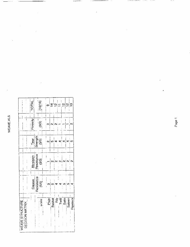
Decision Matrix for Weave Selection
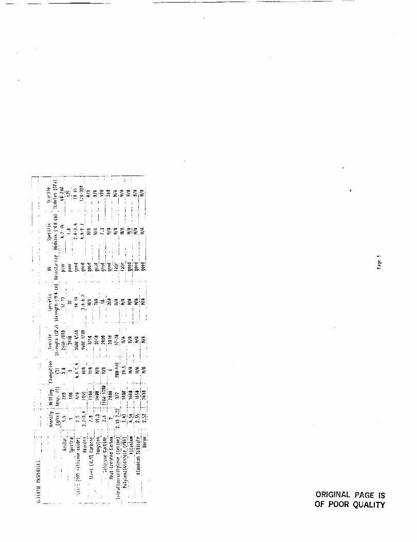
Material Data Sheet
Alternative Deployment MethosAlternative Stowage Methods
Stress Analysis of MatRocket Engine Plume Analysis
Projectile Force Calculations
Vehicle Parameter AnalysisFabric Characterisitics
Fabric Samples
Glossary
PAGE #
1
2
3
5
14
16
A
B
CD
E
F
G
H-
I
J
K
L
M
References
Acknowledgements
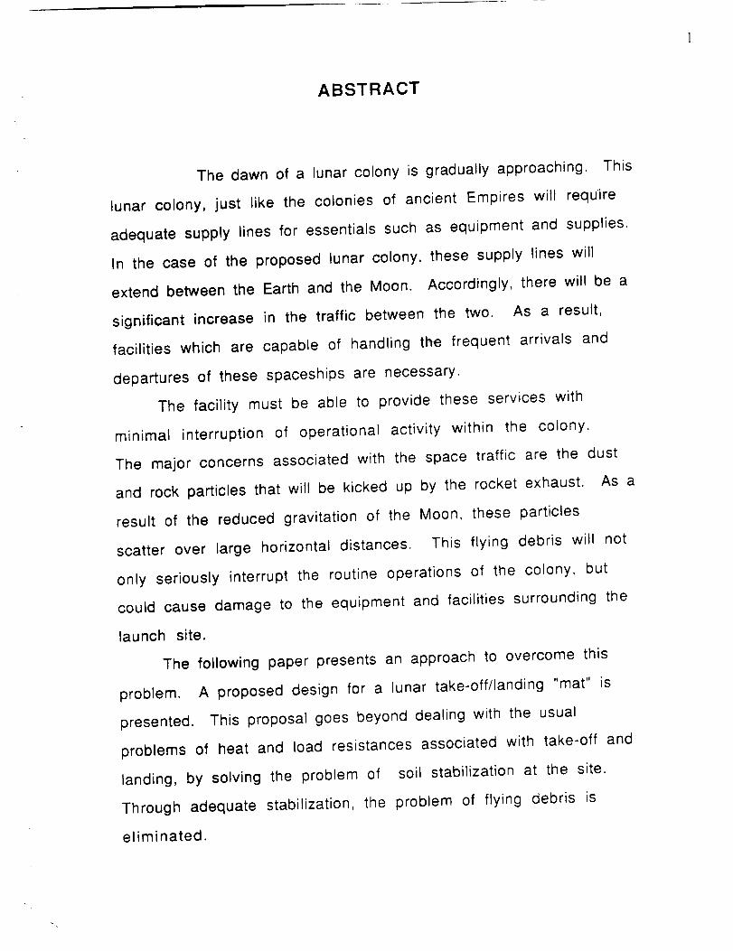
ABSTRACT
The dawn of a lunar colony is gradually approaching. This
lunar colony, just like the colonies of ancient Empires will require
adequate supply lines for essentials such as equipment and supplies.
In the case of the proposed lunar colony, these supply lines will
extend between the Earth and the Moon. Accordingly, there will be a
significant increase in the traffic between the two. As a result,
facilities which are capable of handling the frequent arrivals and
departures of these spaceships are necessary.
The facility must be able to provide these services with
minimal interruption of operational activity within the colony.
The major concerns associated with the space traffic are the dust
and rock particles that will be kicked up by the rocket exhaust. As a
result of the reduced gravitation of the Moon, these particles
scatter over large horizontal distances. This flying debris will not
only seriously interrupt the routine operations of the colony, but
could cause damage to the equipment and facilities surrounding the
launch site.
The following paper presents an approach to overcome this
problem. A proposed design for a lunar take-off/landing "mat" is
presented. This proposal goes beyond dealing with the usual
problems of heat and load resistances associated with take-off and
landing, by solving the problem of soil stabilization at the site.
Through adequate stabilization, the problem of flying debris is
eliminated.
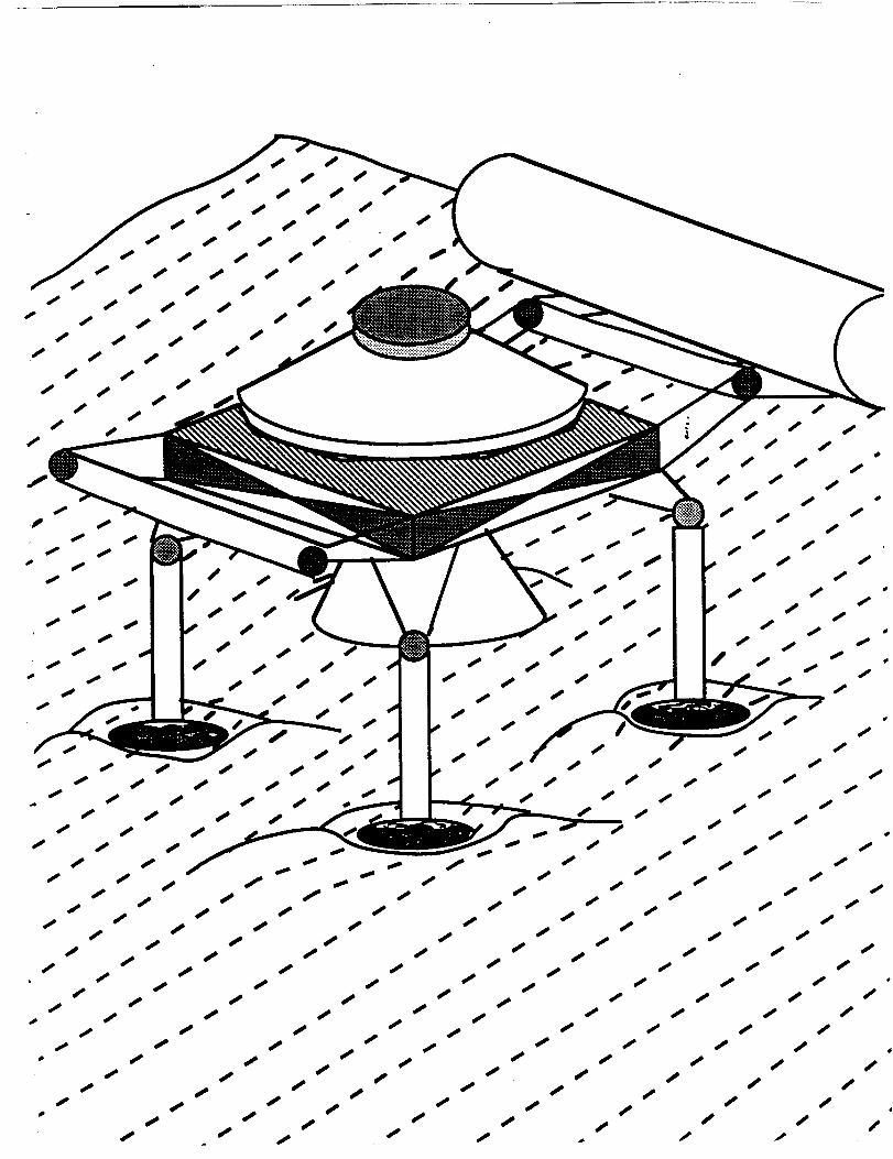
PROBLEM STATEMENT
With the advent of a lunar colony, a need arises for facilities
to handle frequent arrivals and departures of transport vehicles
from Earth. Specifically, a launch/landing pad capable of
accommodating these vehicles is necessary. These subsequent take-
offs and landings should not interfere with any ordinary, everyday
routine operations of the colony. One problem of significant concern
is the dust and rock particles which will be kicked up by the rocket
engines. Due to the reduced gravity on the moon, these particles
travel significant horizontal distances from the actual landing site.
This flying debris could interrupt the routine of the colony and even
result in significant damage to equipment or injury to personnel,
therefore, this problem must be eliminated.
The objective of this project is to provide adequate soil
stabilization for the proposed launch/landing site. The design must
provide a structure or surface capable of accommodating a
spacecraft and protection from flying particles. In addition, the
design must be of adequate size to guard against landing errors.
Lastly, the pad should be capable of withstanding one landing/launch
sequence every three months over a lifetime of ten years. The
constraints in the design include:
1. adequate heat resistance for take-off
2. sufficient impact resistance on landing
3. resistance to radiation (UV and Gamma)
4. ease of transportation and deployment
5. low weight
The mat is 66 mils or 0.066 inches thick and weighs
approximately 30,500 pounds. The carbon fiber mat is produced by
joining together forty fabric panels that are 100 meters long and 2.5
meters wide. Forty fabrics panels are necessary to cover a one-
hundred meter square area. These panels are stitched together using
double stitched and flat-felled seams. The strongest seams are
double-stitched and flat-felled, A carbon yarn will be used for the
stitching. Hand sewing may be necessary when stitching.
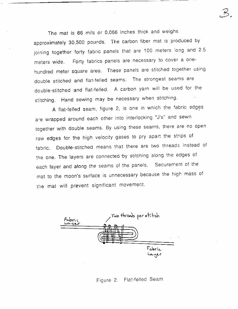
A flat-felled seam, figure 2, is one in which the fabric edges
are wrapped around each other into interlocking "J's" and sewn
together with double seams. By using these seams, there are no open
raw edges for the high velocity gases to pry apart the strips of
fabric. Double-stitched means that there are two threads instead of
the one. The layers are connected "by stitching along the edges of
each layer and along the seams of the panels. Securement of the
mat to the moon's surface is unnecessary because the high mass of
the mat will prevent significant movement.
II" Is; lit' l[ _x
Figure 2. Flat-felled Seam
DESCRIPTION
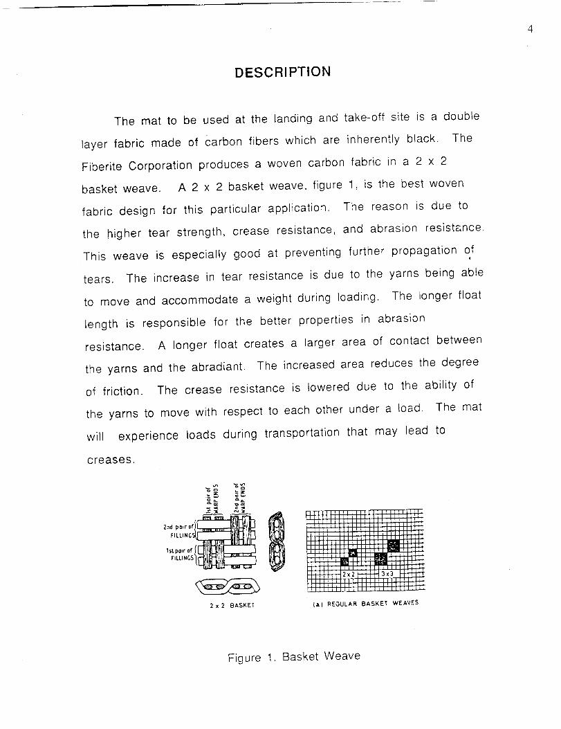
The mat to be used at the landing and take-off site is a double
layer fabric made of Carbon fibers which are inherently black. The
Fiberite Corporation produces a woven carbon fabric in a 2 x 2
basket weave. A 2 x 2 basket weave, figure 1, is the best woven
fabric design for this particular application. The reason is due to
the higher tear strength, crease resistance, and abrasion resistance.
This weave is especially good at preventing further propagation ofi
tears. The increase in tear resistance is due to the yarns being able
to move and accommodate a weight during loading. The longer float
length is responsible for the better properties in abrasion
resistance. A longer float creates a larger area of contact between
the yarns and the abradiant. The increased area reduces the degree
of friction. The crease resistance is lowered due to the ability of
the yarns to move with respect to each other under a load. The mat
will experience loads during transportation that may lead to
creases.
o_,,aGk._.
FILLING_
,,,po,ro,/_till_!i_ZZZ::3
2 x 2 BASKET
IT IIJ'_JJ}JlIJ]JJIJJ
lilil]l]_lllllllllilIIIIIII ]llltlll
lii"llllIlilll[llllll!!!IIIIIIIIIIIIIIIII,.lIltlt][ll IIi]l[lllll]ll} _lilltl II11111!1111 1
i!l lilT|
ITililllI[ _IIIIII
i_liilfl(llllllilllliiLllllllllllIllllt|[lll_llllll}lllllll[l
F_
i r,
I]i
12x_
(a} REGULAR BASKET WEAVES
Figure 1. Basket Weave
5
ANALYSIS
A. Soil Characteristics
The composition of the lunar surface is categorized in the
following manner. The very top surface layer consists of extremely
fine particles. These particles are similar in nature to those that
are found here on Earth on certain "volcanic beaches". This layer is
approximately 5 cm deep. Below this layer, there exists a very
dense, compressed layer of regolith. The purpose of this design is to
prevent the soft surface layer from being scattered by the rocket.
The mat's design prevents particles of greater than 1 micrometer
from passing through the mat.
B. Material
The strategy of material selection for a launch and landing mat
involves finding a fabric that adheres to the following criteria: low
porosity, low density, as well as resistance to heat, tears, and
radiation (UV, Gamma). These parameters are extremely important
for lunar applications. Other criteria are important, but the above
stated parameters are the most important in order to prevent major
mechanical failures of the mat. Investigation of various materials
leads to a list of possible classes of fibers. These classes are
metal, organic, and ceramic fibers. Carbon fibers possess the
characteristics needed for this lunar application. There are various
methods of producing carbon fibers. These processes involve
precursors such as polyacrylonitrile (PAN), cellulosic (rayon), and
pitch. PAN and rayon precursors result in moderate to high modulus
6
fibers. The pitch based fibers are capable of having low or high
modulus carbon fibers, but are not strong enough for this design
application. The fabrication of carbon (PAN) fibers is covered in
Appendix A. This lunar application demands a fiber with a moderate
modulus to prevent permanent creasing of the mat during the
transportation to the moon. A PAN based carbon fiber woven fabric
is produced by the Fiberite Corporation.
Porosity is important for the launch and landing mat due to the
high velocity gases that the mat will be exposed to. Using two
layers will greatly reduce the amount of gases that will penetrate
to the moon's surface. The weave of the fabric must prevent as
much of the gases as possible from penetrating the fabric, thus
reducing the chances of the mat to fail mechanically. If the soil
escapes through the mat, erosion of the space craft as well as any
structures in the surrounding area is possible. The second layer of
the mat will greatly reduce the chances of debris from fully
escaping through the mat as well as adds extra strength.
Density is important because the cost of transporting the mat
in the space shuttle is extremely high (25,000 dollars/pound)
compared to any production costs. Common metallic wire densities
range from 7 to 20 g/cc. The densities of organic materials are
lower, they range from 1 to 4 g/cc. The densities of ceramic fibers
range from 1.5 to 8 g/cc. Carbon fiber densities range from 1.6 to
2.3 g/cc. Organic and ceramic fibers appear to be the best choice
when considering only densities. Organic fibers are unacceptable
due to other factors that will be addressed in the following
sections. The density of the carbon fiber being used in the mat is
1.91 g/cc. The maximum cargo load of the space shuttle is 60,000
pounds. The weight per unit area of one layer of fabric is 20.00
oz/sq.yd, therefore, the double layer weight is 30,500 pounds. This
value includes the extra weight of threads for the seams and is
based on an area of 100m x 100m. The seam weight is based upon
two percent of the weight of a single layer.
Heat resistance is important because of the temperatures
encountered during landings and take-offs from the moon. The
maximum temperatures from the exhaust gases are approximately
1500 degrees Celsius, however, the maximum exposure time is only
a few seconds. Ceramic and metallic fibers are capable of
withstanding this temperature range and exposure time. The melting
temperatures of metallic fibers range from 1300 to 2600 degrees
Celsius. The organic fibers are only capable of enduring
temperatures of approximately 200 to 300 degrees Celsius. The
melting temperatures of ceramic fibers are approximately from 800
to 3600 degrees Celsius. The maximum temperature usage for
carbon fibers is approximately 2000 degrees Celsius.
Tear resistance is important due to the forces that will be
endured during landings as well as the deployment of the mat. The
lunar surface is not level, therefore, consideration of the
possibilities of tears need to be addressed. Lunar rocks are present
on the moon and are not capable of being cleared from the proposed
landing area. The mat must be capable of withstanding the forces
applied to the mat over the rocks. The use of a basket weave
increases the tear resistance in the warp and weft direction. This
effect is due to the yarns in the mat being able to move with respect
to one another which presents bundles of yarn to the load, therefore,
increasing the tear resistance. The tear will not propagate using the
basket weave.
All types of radiation are important because the mat should
not deteriorate upon exposure. This deterioration often results in a
major loss in mechanical properties. The organic fibers degrade and
lose mechanical properties when exposed to ultra-violet and gamma
radiation. Metallic and ceramic fibers are capable of retaining
mechanical properties with exposure to these types of radiation.
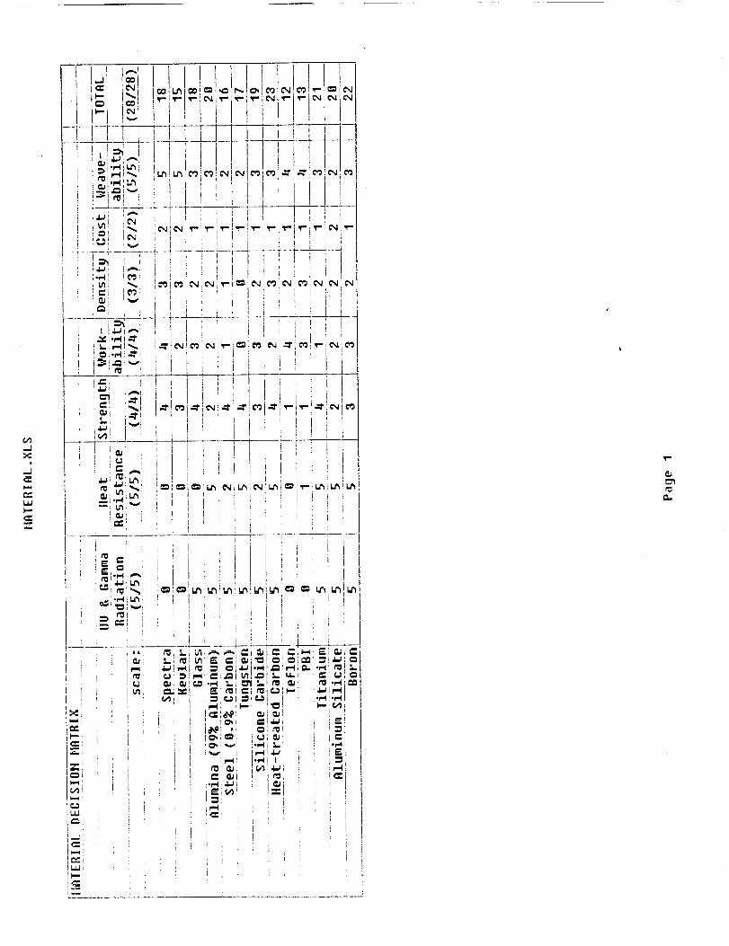
The criteria addressed in the above paragraphs enables a
decision to be made on the selection of a material. The advantages
and disadvantages of each class were given in the preceding
paragraphs. A decision matrix was used to aid in the material
selection and can be found in Appendix B. Evaluation of the criteria
and the decision matrix lead to the decision to use carbon fibers.
The carbon fibers are the only class that effectively adhere to all of
the criteria.
C. Stowage
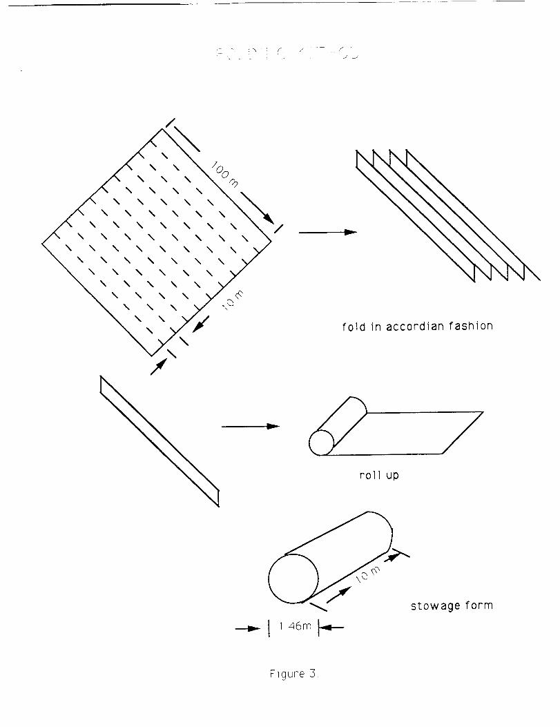
The mat is to be stowed on board the space shuttle for
transport to the moon. It is therefore mandatory that the 100m x
100m mat be able to fit into the 12m x 6m x 6m volume of the space
shuttle bay. The folding method involves folding the mat in an
accordion fashion in one direction and then subsequently rolling it in
the other direction. This method is shown in figure 3 of the
following page. Considerations in determining the folding scheme
primarily involve reducing the volume of the mat to proportions
I
\
\\
\\
\
\\
\\
\\
\\
\
\\ \
\ \ \\ \ \ \
\ \ \\ \ \ \
\ \ \\ \ \ \
\ \ \\ \ \ \
\ \ \\ \ \ \
\ \ \\ \ \
\ \\
\\
X
\\
\\
\\
\
\
\\ r
fold in accordian fashion
v
roll up
stowage form
---iP- I 1 46m I-4-_
Figure 3
acceptable for the shuttle. The design chosen minimizes this
volume. The other consideration is the possibility of over stressing
the mat at the folds if it is over folded. This situation may result in
significant tearing or other mechanical failures. The use of of 2 x 2
basket weave helps to eliminate the amount of stress at the folds on
the mat. This design also minimizes the number of folds to an
acceptable level.
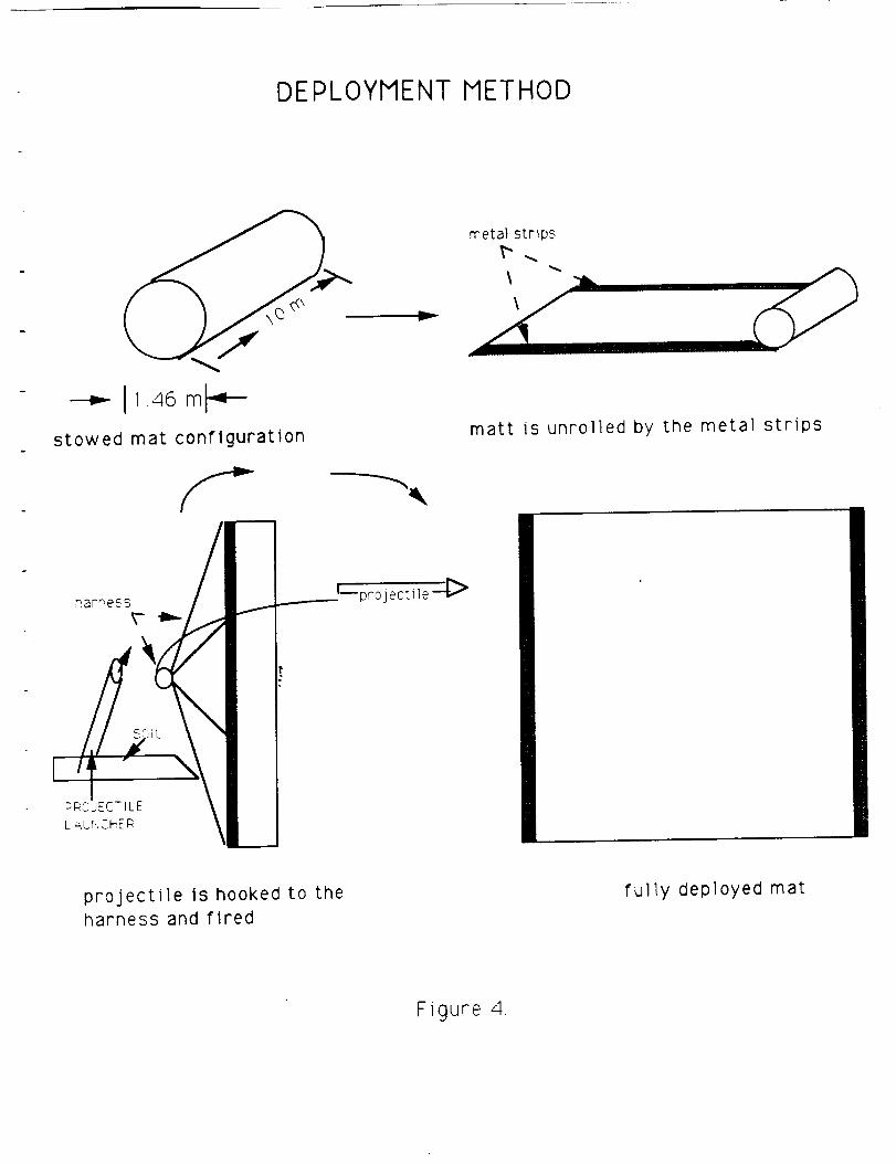
D. Deployment
The method for deploying the mat is shown in figure 4 of the
following page. First the mat is to be unrolled by metal strips
which were rolled up inside the mat. These strips serve as coil
springs and give the necessary rotational force. Unfolding the mat
is accomplished by a harpoon like device. The harpoon is to be
attached to the edge and then fired in the direction of unfolding,
with sufficient thrust, the harpoon carries the mat to a nearly
deployed state. Minor adjustments as needed can be done either by
humans or a small robot
E. Vehicle Parameters
The lunar mat is designed for the landing and launching of
space vehicles. The size of these vehicles vary from approximately
11 to 62 feet in length and 10 to 20 feet in diameter. The ranges of
weight of these vehicles are 20,000 to 35,000 pounds plus a cargo
weight up to 60,000 pounds. Therefore, the total load reaches a
maximum weight of 95,000 pounds on Earth.
DEPLOYMENT METHOD
_i.. I1.4_ml_-stowed mat configuration
harness
v
projeetlle_._>
metal strips
matt is unrolled by the metal strips
projectile is hooked to theharness and fired
fully deployed mat
Figure 4.
I 0
The exhaust components consist mainly of hydrogen and
oxygen. The specific thrust is proportional to the velocity. The
ratio is given by 100 (ft/sec) : 3.1056 ((Ibf-sec)/Ibm). The thrust
force can be computed by multiplying the specific thrust by the fuel
rate. The average fuel rate is approximately 50.1 (Ibm/sec).
F. Performance
1. Take-off
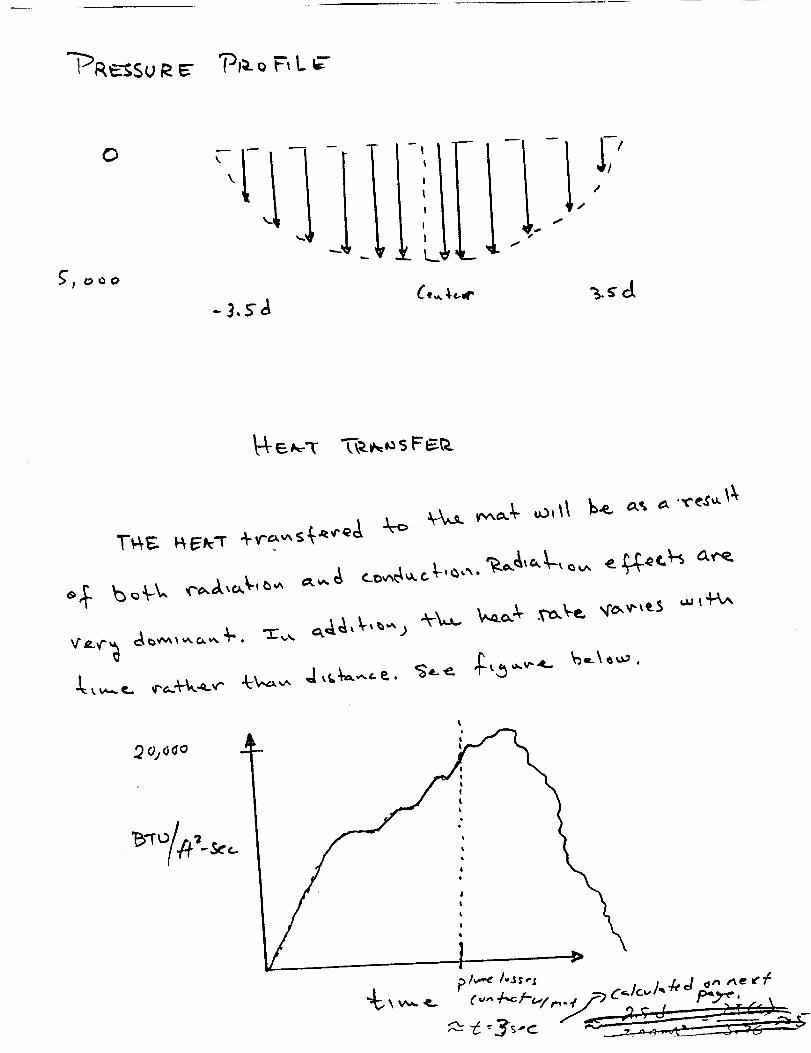
The primary concerns on take-off are the heat of the exhaust
gases and the thrust forces associated with the exhaust velocity.
With respect to heat parameters, an investigation of the technology
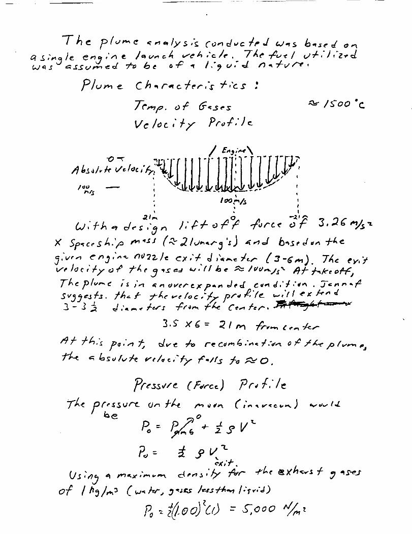
of rocket plumes is necessary (such an analysis may be found in
Appendix H). All results presented here are based on plume
calculations involving a rocket of approximately 95,000 pounds
powered by a single engine. Assuming that the fuel to be utilized is
liquid oxygen, the maximum temperature of the exhaust gases to be
anticipated is approximately 1500 degrees Celsius. Since the mat is
constructed uniformly of carbon fibers, which have a temperature
resistance of approximately 2000 degrees Celsius, there will be no
significant problems with material breakdown. Furthermore,
because of the 500 degree safety margin, the pad should be able to
hold up in the event of minor modifications in rocket fuel
composition which would cause an increase in exhaust temperature.
The anticipated thrust force is approximated by the specific
thrust ratio presented earlier. For this determination, the diameter
of the rocket varies from approximately 3 to 6 meters in diameter
at the exit. These nozzle sizes yield a maximum velocity of
11
approximately 100 m/s^2. Applying the maximum anticipated
specific thrust factor, a thrust force of approximately 100 kilo-
newtons is calculated. Subsequent stress analysis of the mat ( see
Appendix G) indicate that the material has a sufficient margin of
safety against failure,
2. Landing
The landing sequence will subject the mat to two different
conditions. First, the mat will be subjected to rocket blasts that are
used to decelerate the vehicle. Secondly, the mat will experience
the impact of the craft as it lands. Regarding the rocket blasts the
following reasoning was imposed. The duration of these blasts is
significantly less than the amount of time that the mat will
experience the take-off blasts, therefore heat conduction and
porosity effects will not present any concern. Since the rocket
utilizes the same fuel as employed in launching, the temperature
will not exceed the take-off temperature; therefore, these effects
are negligible. The impact force is approximated as being equal to
the force obtained were the mass of the space ship dropped from a
height of 2 meters. This would equate to a force of about 300 kilo-
newtons; this is clearly less than the associated thrust force which
would be experienced. As a result, the mat will perform equally
well on landing.
12
G. Weight/Mass/Inertia
The weight of a single layer mat is 20.00 oz/sq.yd. This
weight is based on a 2 x 2 basket weave. The mat is going to be two
layers with a thickness of 66 mils. The total weight will be
approximately 30,500 pounds. The mat will not be moving,
therefore, the inertia is zero.
H. Casualty Information
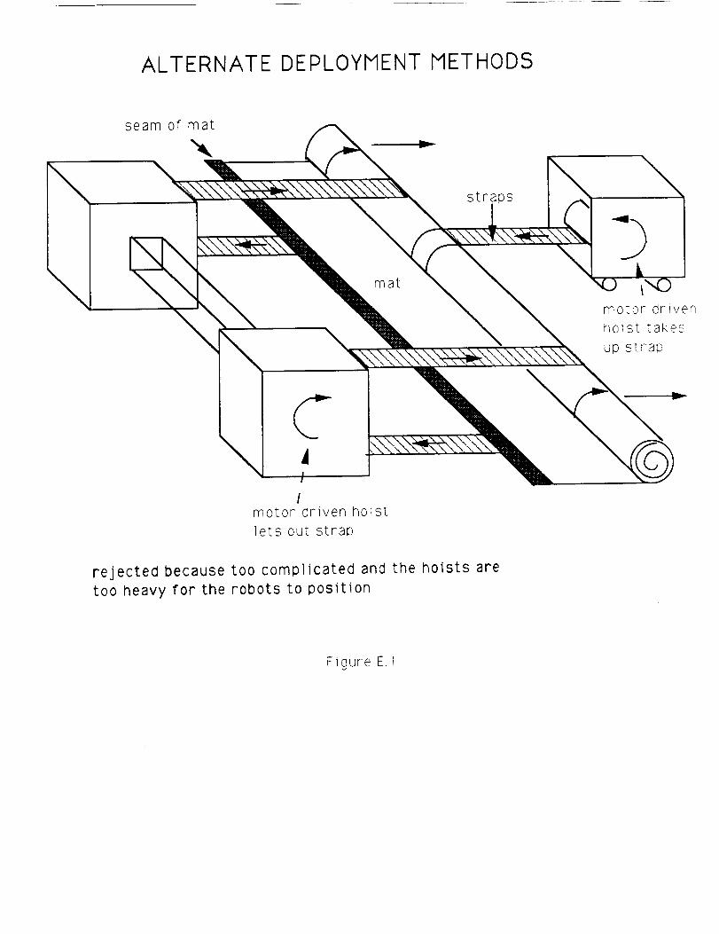
1. Alternate Deployment Method
An alternative deployment method is necessary if the mat can
not be properly deployed. The causes for this situation may be due
to failure of the rockets or robots. If this situation occurs, the
necessary action is to obtain additional rockets or robots.
2. Repair of Damage
The probability of a tear propagating through the mat is
necessary to consider. The surface of the moon is not level and
rocks may be 3resent underneath the mat. During a landing a tear
may initiate if the landing is near the site of the rock. Having two
layers of fabric will greatly minimize the probability of tearing
both layers. The mat will continue to work satisfactorily with only
one working layer. The 2 x 2 basket weave is especially good with
the prevention of tear propagation because of weave structure.
I. Maintenance
The carbon fiber mat will not require any maintenance.
13
J. Cost Analysis
The approximate cost of the mat includes the manufacturing,
and transportation cost. The approximate cost of carbon fibers are
in the range of 1000 dollars per pound. This cost only represents the
production of the fiber. Weaving costs are going to approximately
100 million dollars. The space shuttle transportation cost will be
approximately 25,000 dollars per pound. With an approximate mat
weight of 31,000 pounds the total cost will be 775 million dollars.
The approximate cost of the deployment will be 2 million dollars.
This value includes the cost of robots, rockets, and a harness. This
cost is small in comparison to the transportation cost.
14
CONCLUSIONS
The objective of this project was to design a soil stabilization
mat to be employed by a lunar colony for the Take-off and landing of
various transport vehicles. During the course of this design, all the
conditions to be encountered during launch and landing were
investigated. On landing, the effects of the accompanying impact
were examined. A force analysis was performed to observe how the
mat would react. The results of this analysis revealed that the
material was indeed of sufficient strength to prevent punctures or
tears caused by sharp particles underneath the mat. This was
primarily due to the fact that the mat was not in a prestressed state
(which would be present as a result of being stretched or anchored).
For the launch sequence a more detailed analysis was
performed. The two primary considerations were the thrust force
and temperature/heat transfer values to be anticipated. An
approximation for the thrust force was obtained using the specific
thrust ratio. The temperature effects were estimated after a
judicious analysis of typical, single-engine rocket plumes. In both
these areas, the mat performed well. There was a 500 degree
excess in temperature resistance and an acceptable difference
between anticipated loading and estimated failure loads.
Lastly, the porosity of the material was sufficiently low
enough to prevent nearly all of the gases from penetrating through.
This, in addition to the fact that the blast should terminate
approximately 25 m from the edges, should ensure adequate
stabilization of the soil. The facts above, together with the
]5
efficient stowage and deployment methods proposed should prove
the mat to be a very successful design.
16
RECOMMENDATIONS
Following the detailed analysis presented above, the following
recommendations are hereby made. Since the material selected for
the mat performed very well in all the critical areas, we suggest
that it be employed. Regarding the stowage method, the proposed
method is not only simple, but easily fits into the Shuttle cargo bay
with plenty of room for other items. It is therefore recommended
also.
The deployment method, however, is not as overwhelmingly
convincing. The proposed method will work, however, (as noted) in
the event of failure, the mat would be difficult to deploy via
alternate means. As the sophistication of robots increases, we
recommend that further analysis be conducted to possibly find a
method which might prove more versatile. We also recommend that
there be astronauts present during the deployment who might be able
to make corrective adjustments in the event the mat does not deploy
as planned, or the robots prove inadequate.
Appendix A
The Fabrication of Carbon (PAN) Fibers
The following paragraphs describe some of the processes
necessary to convert the polyacrylonitrile (PAN) fibers into
workable carbon fibers. A possible problem with the mat being
made of carbon fibers is the possibility of mechanical failure at the
folds when the mat is folded into the cargo space. The carbon fibers
are inherently brittle and thus tend to break with excessive bending.
Without the proper equipment it is beyond the scope of this paper to
guarantee that the mat could withstand the stresses at the folds
provided the carbon fibers are prepared properly for manufacturing.
There are three precursors used for the production of carbon
fibers, including polyacrylonitrile, rayon and other cellulosic fibers,
and pitch based fibers. Polyacrylonitrile (PAN) fibers are favored
over cellulosic and pitch based fibers due to ease of processing and
greater end-use strengths. PAN fibers are heated in oxygen to
produce carbon fibers. Carbon fibers produced from PAN fibers have
a higher modulus of elasticity than the others, which means that
there will be a smaller elongation at break. Special care is required
during process operations because the individual filaments in the
yarn tend to break easy. The partial breakage of filaments results in
yarns which contain large amounts of stray filaments oriented at
various angles to the axial direction of the yarn. During further
manufacturing processes, small fragments of the stray material are
broken off to form an "aerosol" of very short carbon fibers, which is
highly undesirable. Bromination is a process that will reduce this
problem. High modulus carbon fibers cannot easily be pushed into
tightly packed configurations such as a woven cloth, unless the
fibers undergo a bromination process. Bromination results in a
lowering of the modulus of elasticity which increases malleability.
Qnce the fabric is formed the plasticizer (bromine) is removed.
Weaving carbon fibers is extremely difficult unless a size is used. A
size is a protective coating which is added to yarns prior to
weaving. This coating is necessary because the process of weaving
is very abrasive, and since the carbon fibers are brittle they are
susceptible to mechanical failure. A dilute solution of a mixture of
liquid and solid epoxy resins is found to be ideal. The size will be
removed after the formation of the fabric.
It is found that a maximum strain at break of 1% is achieved
after a heat-treatment at 1500 degrees Celsius. A strain of 0.5% is
achieved with heat-treatment at 2600 degrees Celsius. This
indicates that for this design a heat-treatment at 1500 degrees
Celsius would be appropriate. Fiber modulus increases with a higher
heat-treatment temperature (HTT), but strength generally decreases
at 1500 degrees Celsius and continues to decrease at higher
temperatures. At a HTT at 1500 degrees Celsius, the fiber strength
and strain rate are at a maximum, and thus would be the best
temperature to heat treat the PAN fibers.
A very important characteristic of carbon fibers is a low
coefficient of thermal expansion. Due to the extreme temperatures,
a low coefficient of thermal expansion will result in minimal
deformations due to temperature changes.
Prestressed fiber compactions represent a means of achieving
high bearing stress levels with relatively low wear rates. It
appears that crushing the fiber ends produces a thin layer of fiber
debris and thus results in a smooth wear surface. This described
mechanism coupled with the already low coefficient of friction
suggests that the mat will experience very reduced shear stresses.
E. M. Lenoe performed tests on carbon fabrics which show that
carbon fabrics can withstand extreme normal stresses. A 1/2 inch
diameter steel indenter was forced into typical specimens. The
fibers showed to be capable of supporting high bearing stresses with
fairly small deflections.
Appendix B
Decision Matrix for Material Selection
I+ --! v !1..... -- .:-=--_---L---_---+- _+....',_ l i +, .I.__ i .'-.,L I
I t +I !i p -1 i Ii !
, i I _i , I
I ,I It i
, !
i + i i :, 1I I
[
I _ _i_I =i= _ _'+,_1 '_
I{.,} i i ' '
I"_ _ I_ i :
i~ill
I •
[
_, +!i
I_ I "
I
Appendix C
Decision Matrix for Weave Structure
._J×W
w
i.Jl
L° ki !-
ii' i
L_!t I
!!lI_il
llrit_t
i_i il
----Tin--
_ i i i i Lt_
I
_×
_z
T--
_J

Appendix D
Material Data Sheet
._ i ¸-
, , • !
" ' 'A ........
w
......................................... " ............. i
_ _ _ _ ._ ,'_ ,.__
c...
ORIGINAL PAGE IS
OF POOR QUALITY
Appendix E
Alternative Deployment Methods
ALTERNATE DEPLOYMENT METHODS
\
seam of mat
\ mat
motor driven
hoist [akes
up s t raL',
C/
motor driven hoist
lets out strap
rejected because too complicated and the hoists are
too heavy for the robots to position
Figure E, 1
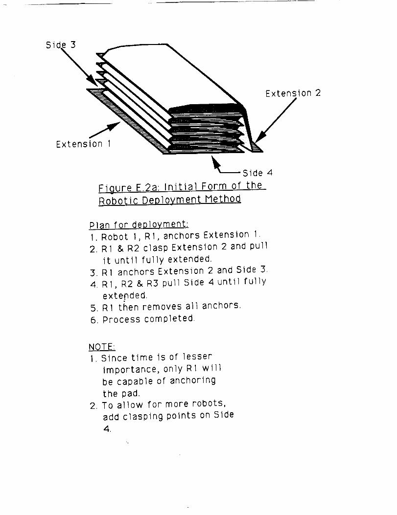
S 3
Extension 2
Extension 1
_--- Side
Figure E.2a: Initial Form of the
Robotic Deployment Method
4
Plan for deployment:
1. Robot 1, R1, anchors Extension I.
2. R1 & R2 clasp Extension 2 and pull
it until fully extended.3. R1 anchors Extension 2 and Side 3.
4. R1, R2 & R3 pull Side 4 until fully
exte_nded.
5. R1 then removes all anchors.
6. Process completed.
NOTE:
1. Since time is of lesser
importance, only R1 will
be capable of anchoring
the pad.
2. To allow for more robots,
add clasping points on Side
4.
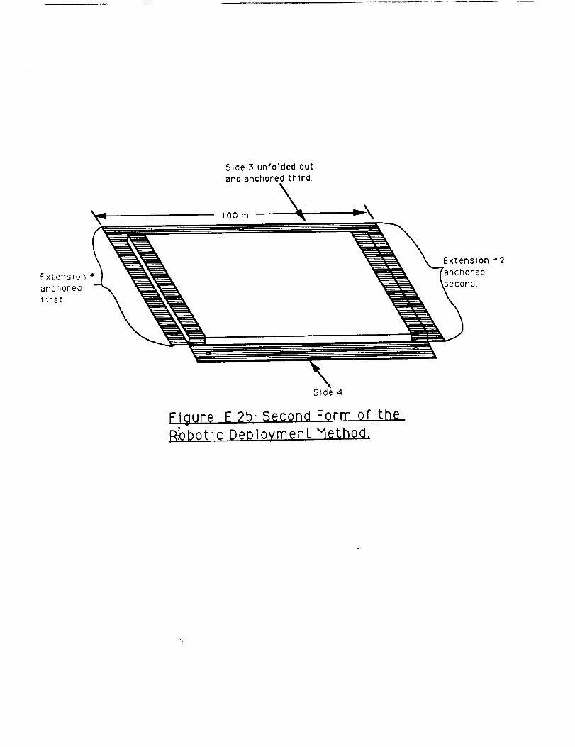
Side 3 unfolded out
and anchored third.
Extenston#
anchored
first
Extension #2
:hored
iecond.
Side 4
Figure E,2b: Second Form ofR_botic Deployment Method,
the
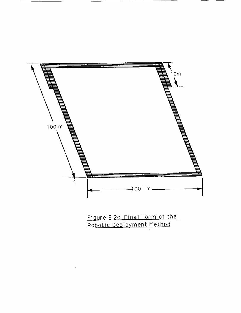
lOm
IO0 m
100 m
Figure E.2c: Final Form of the
Robotic Deployment Method
Appendix F
Alternative Stowage Methods
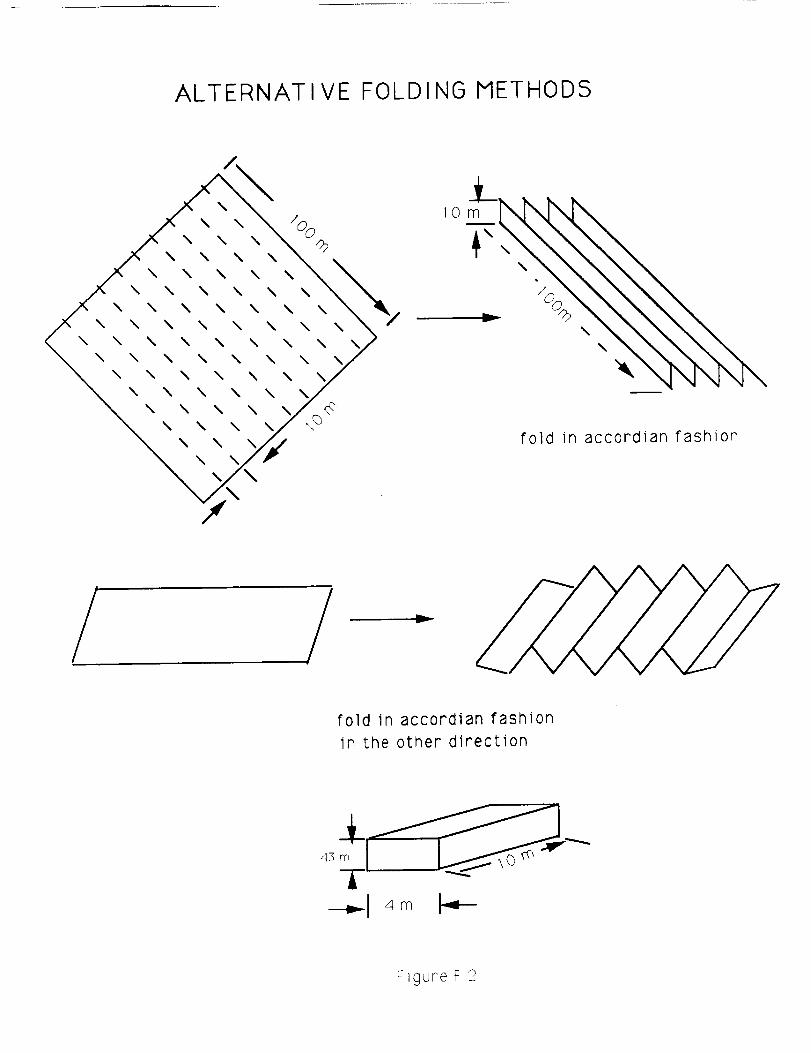
ALTERNATIVE FOLDING METHODS
\
\\
\\
\
\\
\ \\ \
\ \\ \
\ \\ \
\ \\ \
\ \\
\
%\ \ /b
\ \ \\ \ \
\ \ \ \\ \ \ \
\ \ \ \ \\ \ \ \
\ \ \ \ Vf
\ \ \\
\ \
10
fold in accordian fashion
/ v
fold in accordian fashion
in the other direction
F_gure F2
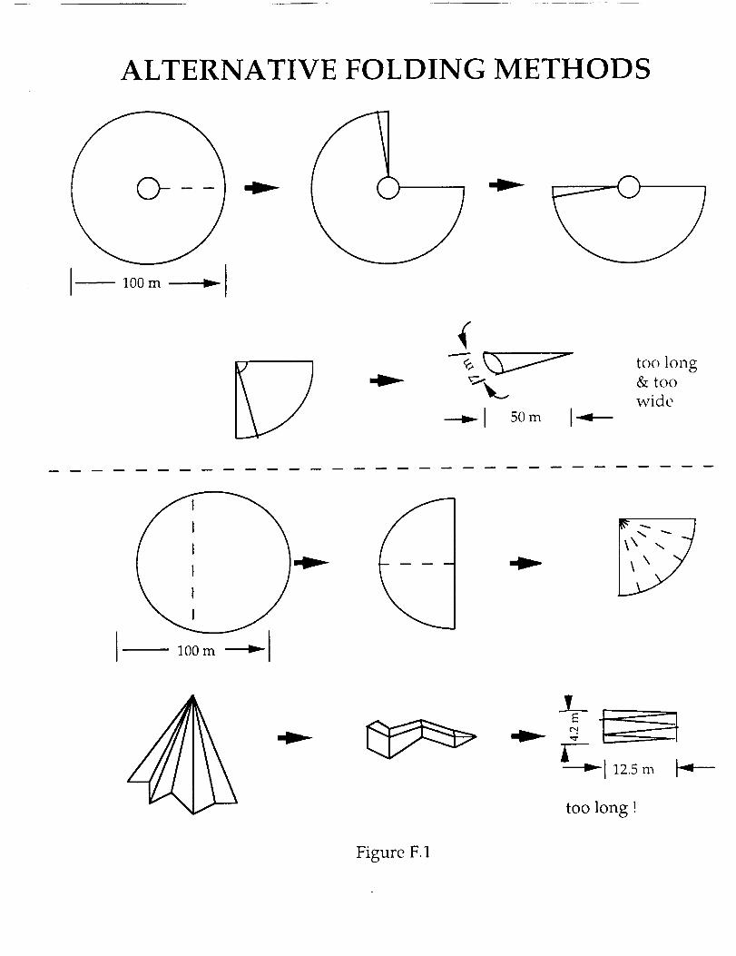
ALTERNATIVE FOLDING METHODS
I 100m _ I
--v;G-------v-1_.,
_1 50m I-4---
too long& too
wide
3__
_--_1125m
too long !
Figure F.1
Appendix G
Stress Analysis of the Mat
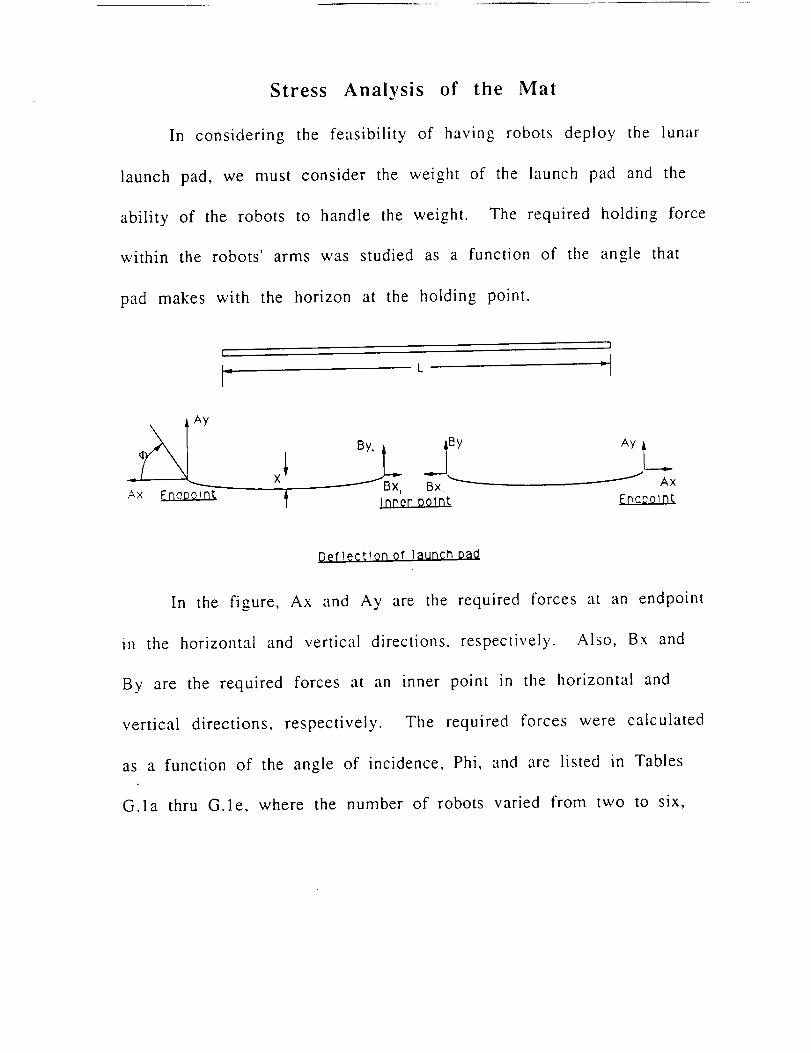
Stress Analysis of the Mat
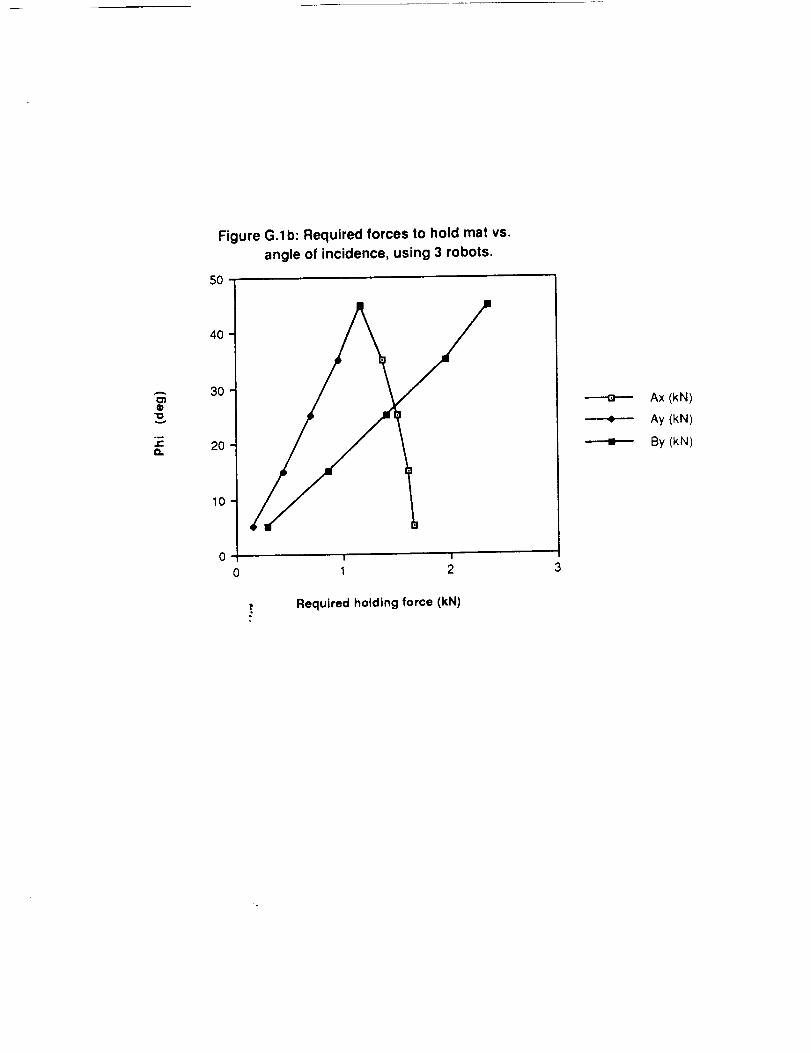
In considering the feasibility of having robots deploy the lunar
launch pad, we must consider the weight of the launch pad and the
ability of the robots to handle the weight. The required holding force
within the robots' arms was studied as a function of the angle that
pad makes with the horizon at the holding point.
I
L
= __ X _Bx, Bx, _ _ AxAx Erlepoint _ Inner Dolnt Enceo_nt
Deflection of launch Dad
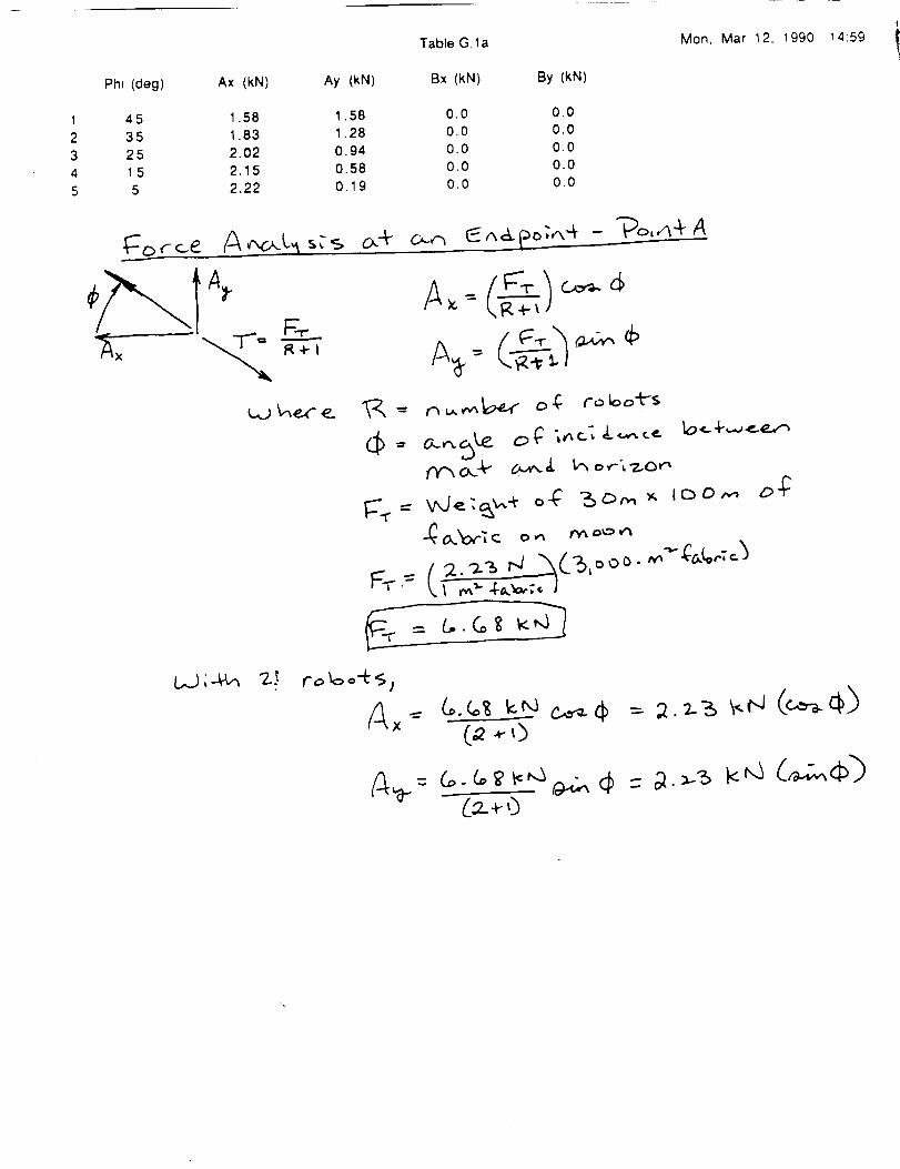
In the figure, Ax and Ay are the required forces at an endpoint
in the horizontal and vertical directions, respectively. Also, Bx and
By are the required forces at an inner point in the horizontal and
vertical directions, respectively. The required forces were calculated
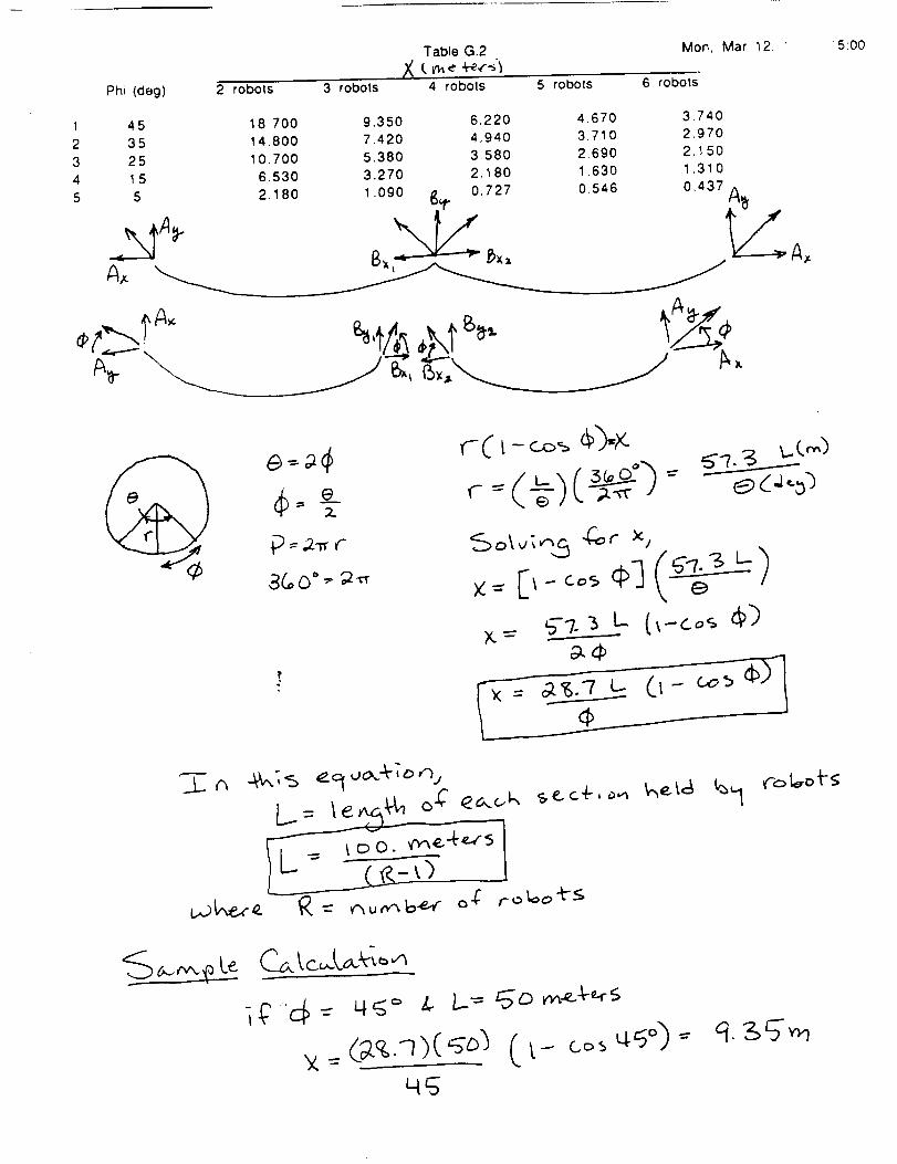
as a function of the angle of incidence, Phi, and are listed in Tables
G.la thru G.le, where the number of robots varied frorn two to six,
respectively. The length, L, of the material is 100 meters. The
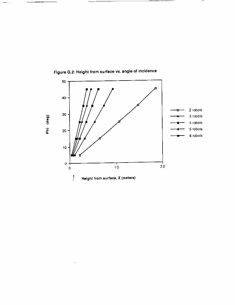
deflection, X, of the mat is calculated in Table G.2 as-:_ function of the
angle of incidence, Phi, and this relationship is shown in Figure G.2.
Sample calculations are shown with Table G.la. Table G.lb and Table
G.2.
TableG.la Mon, Mar 12, 1990 14:59
Phi (deg) Ax (kN) Ay (kN) Bx (kN) By (kN)
1 45 1.58 1.58 0.0 0.0
2 35 1.83 1.28 0.0 0.0
3 25 2.02 0.94 0.0 0.0
4 1 5 2.15 0.58 0.0 0.0
5 5 2.22 0.19 0.0 0.0
C,J ;-4_ ?-._
(_2..4-,)
A
o"o
5O
4O
3O
2O
10
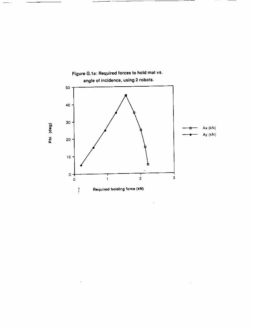
Figure G.la: Required forces to hold mat vs.
angle of incidence, using 2 robots.
! I
0 I 2 3
Ax (kN)
Ay (kN)
Required holding force (kN)
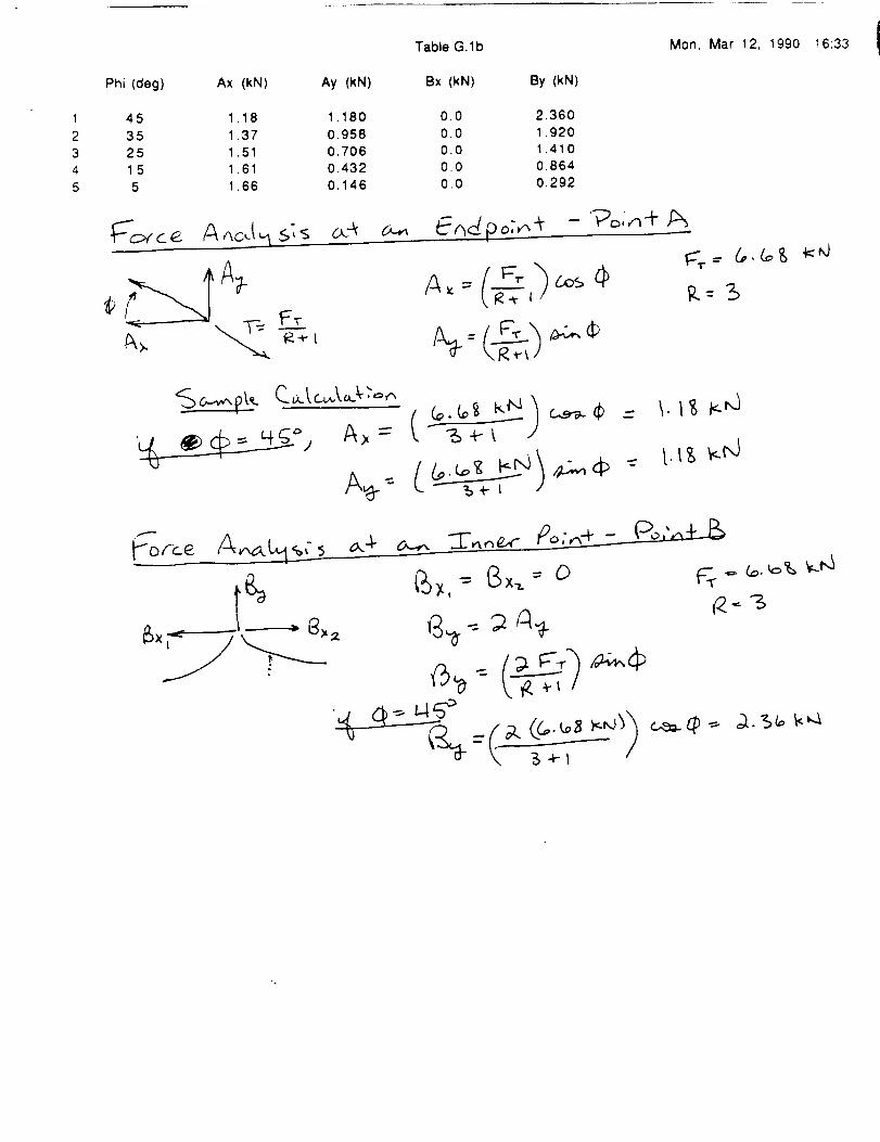
Table G.lb Mon, Mar 12, 1990 16:33
Phi (deg) Ax (kN) Ay (kN) Bx (kN) By (kN)
1 45 1.18 1,180 0,0 2,360
2 35 1,37 0,958 0.0 1.920
3 25 1.51 0,706 0.0 1.410
4 1 5 1.61 0.432 0.0 0.864
5 5 1.66 0,146 0.0 0.292
f"5_ -- _ f4t-
\ #,._l-
_ ...._. ,,=,%',..-_
_..,._
9,.
A
oto
"o
.m
Q.
Figure G.lb: Required forces to hold mat vs.
angle of incidence, using 3 robots.
5O
40
30
20
0 1 2 3
Required holding force (kN)
___..Q-.--
----.11.--'--
Ax (kN)
Ay (kN)
By (kN)
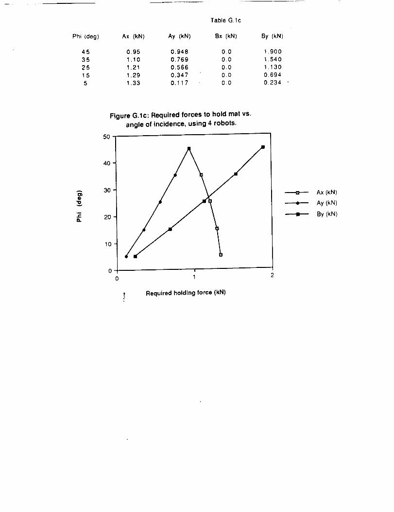
Phi (deg)
Table G. lc
Ax (kN) Ay (kN) Bx (kN) By (kN)
45 0.95 0.948 0.0 1.900
35 1.10 0.769 0.0 1.540
25 1.21 0.566 0.0 1.130
1 5 1.29 0.347 0.0 0.694
5 1.33 0.117 0.0 0.234
A
o"o
Figure G.lc: Required forces to hold mat vs.
angle of incidence, using 4 robots.
50 -
40
30
20
10
I
1
¢
Ax (kN)
Ay (kN)
By (kN)
! Required holding force (kN)
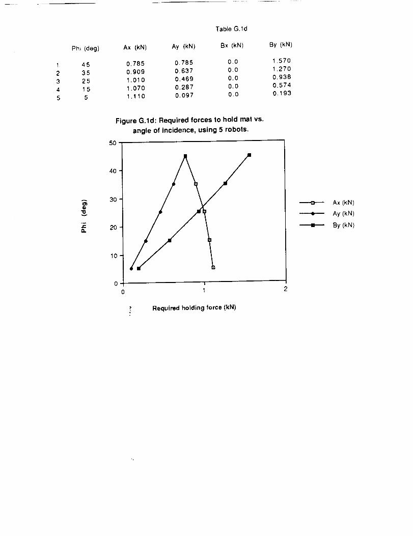
Phi (deg)
Table G. 1d
Ax (kN) Ay (kN) Bx (kN) By (kN)
1 45 0.785 0.785 0.0 1.570
2 35 0,909 0.637 0.0 1.270
3 25 1.010 0.469 0.0 0.938
4 1 5 1.070 0.287 0.0 0.574
5 5 1.110 0.097 0.0 0. 193
A
"o
.me-'
a.
Figure G.ld: Required forces to hold mat vs.
angle of Incidence, using 5 robots.
5O
40
3O
2O
0 1
Ax (kN)
Ay (kN)
By (kN)
," Required holding force (kN)
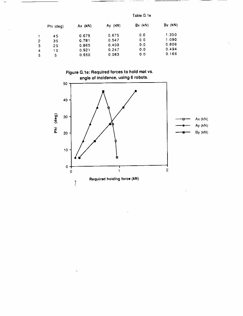
Phi (deg)
Table G. le
Ax (kN) Ay (kN) Bx (kN) By (kN)
1 45 0.675 0.675 0.0 1.350
2 35 0.781 0.547 0.0 1.090
3 25 0.865 0.403 0.0 0.806
4 1 5 0.921 0.247 0.0 0.494
5 5 0.950 0,083 0.0 0.166
v
m
O,.
Figure G.le: Required forces to hold mat vs.
angle of incidence, using 6 robots.
50
4o
30
20
i0 i
0 1
Required holding force (kN)
mm
Ax (kN)
Ay (kN)
By (kN)
Phi(deg)
12345
453525155
18.70014.80010.7006.5302.180
3 robots
Table G.2
4 robots
9.350 6.220
7.420 4.940
5.380 3.58O
3.270 2.180
1.090 (_ 0.727
5 robots
4.6703.710
2.690
1.630
0.546
Mon, Mar
6 robots
3.740
2.970
2.150
1.310
0.437_
12, '
A_
5:00
2.
3(.,,O° _" 2_
_.7 L (_- _ _)|_/
scc+,_ ket_ _1co _,_fs
R. S6-m
A
o_G"o
a.
Figure G.2: Height from surface vs. angle of incidence
5O
4O
3o
2O
10
I
0 10 2O
2 robots
3 robots
4 robots
5 robots
6 robots
"_ Height from surface, X (meters)
Appendix H
Rocket Engine Plume Analysis
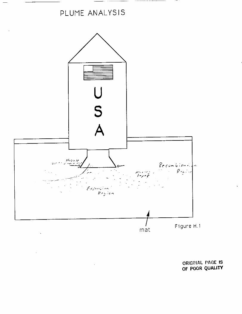
PLUME ANALYSIS
USA
J
Imat
Figure H. I
ORIGINAL PAGE IS
OF POOR QUALITY
_ ,,:+..e __+_ c,,,.,...,e ,_ _ & e o .P .,t I, _ +.,,,,"_ _ ,, ../-.v l'e ,
7"e,,,,p.oF _.,._,._
Ve /oc ,"lj Pr+_t."]
, Ioo,-,I. _i
I
% •
_'" /,. g+ o_°p
× sr+_,sA.'p,',,,.,.+s(_ .2I,.,,.,.+.-_'_] < ,_J 6.,_, d ,,, "H,e
t'_ _ _1,,_ _.,i,<.'_ I
r-e c_,',_ .'." "_t .'o',.t
t./O Yo _ o.
?r,S,l_
0
_o: P_ +i_v _
?<,- _ inK"
0
_j l_O0
I
._qV
I
I
!
I
I
L ,r
l,/
J
_._,._. _e. _t_'-.- _¢_X_,.o.
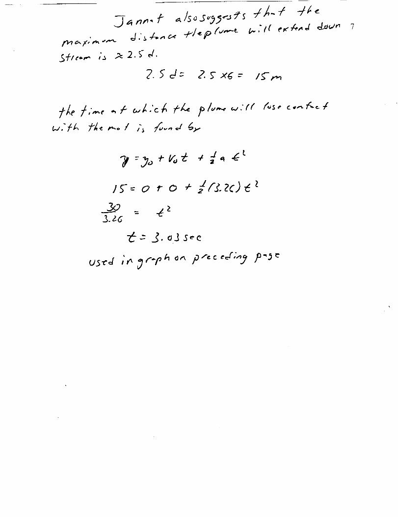
_a n,',., f _/so_"_5-"JCs
.£+t¢..,.., ,_ _ 2. S" d.
2._d- 2. _'xd---
://,.. -/ 4_
V.. ." t ( e _"_,. ,_ d ,Jaw',', 7
/E'r,-,
/5-- o r o , Jf.C.zc)_
23.26" --
_--" 3. oJ S_'c
us-,'d ,',,,_1"n _' o,., p ,_,,"J;",9'
Appendix I
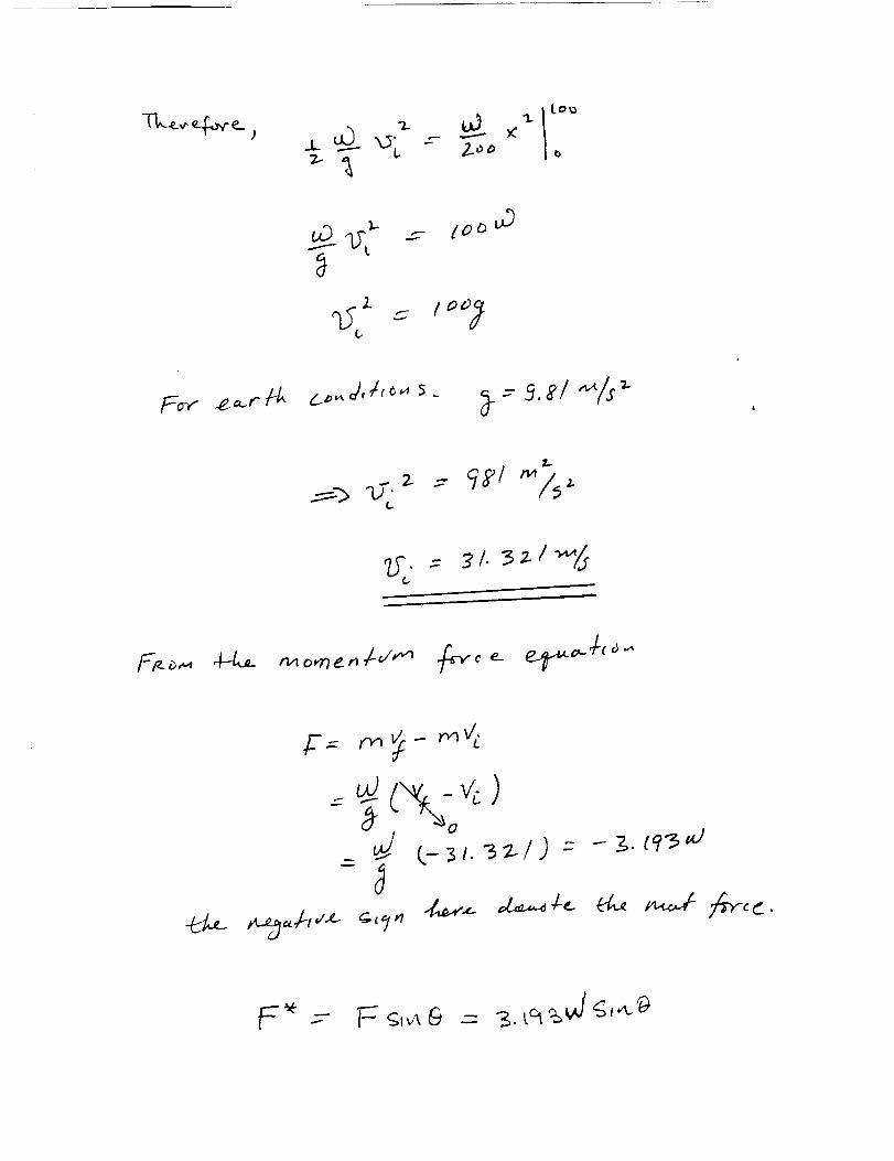
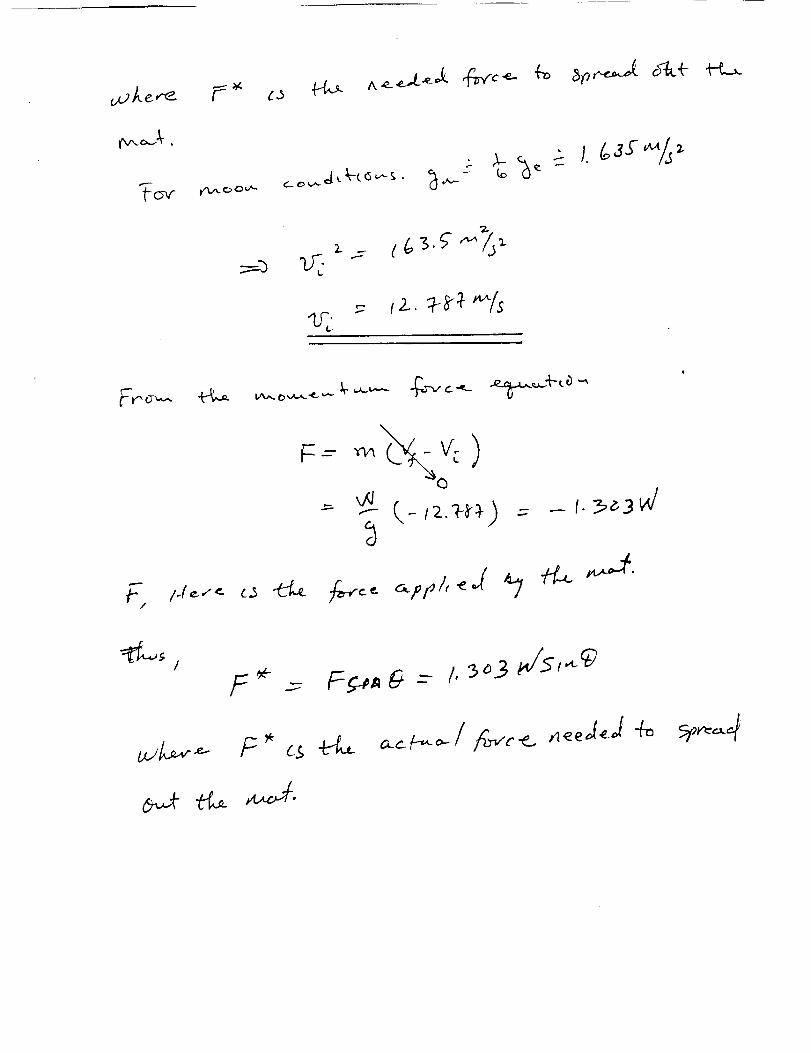
Projectile Force Calculations
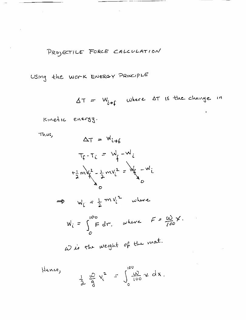
C_ I.c uLA7 r _AZ
Z_'T =-W$
/._.,r' mk.,..,r_
&.T - '_//.
"T_-T L -- \,',J[-v',/. ¢,.
O
_l:...v J..-'r,q_ '_- ,.,oL_..e.
&T" I.S "Z--b,.e..c_.k_,.,,_e.. I!,1
_'/': --" S F: dr"O
F" ..,- u5 .y,
lD _ _ _e,L_ _- _ el_ _d:.
log
0
.L7..
uO___j" _c
Z
I..
.- {o_ u3
$..
7.5", = _ I. _ _ I _'_/3
_ _-_
-j
^ .¢ ¢,.L__d¢
TC_,r __ J. _,.t.£- 2
Appendix J
Vehicle Parameter Analysis
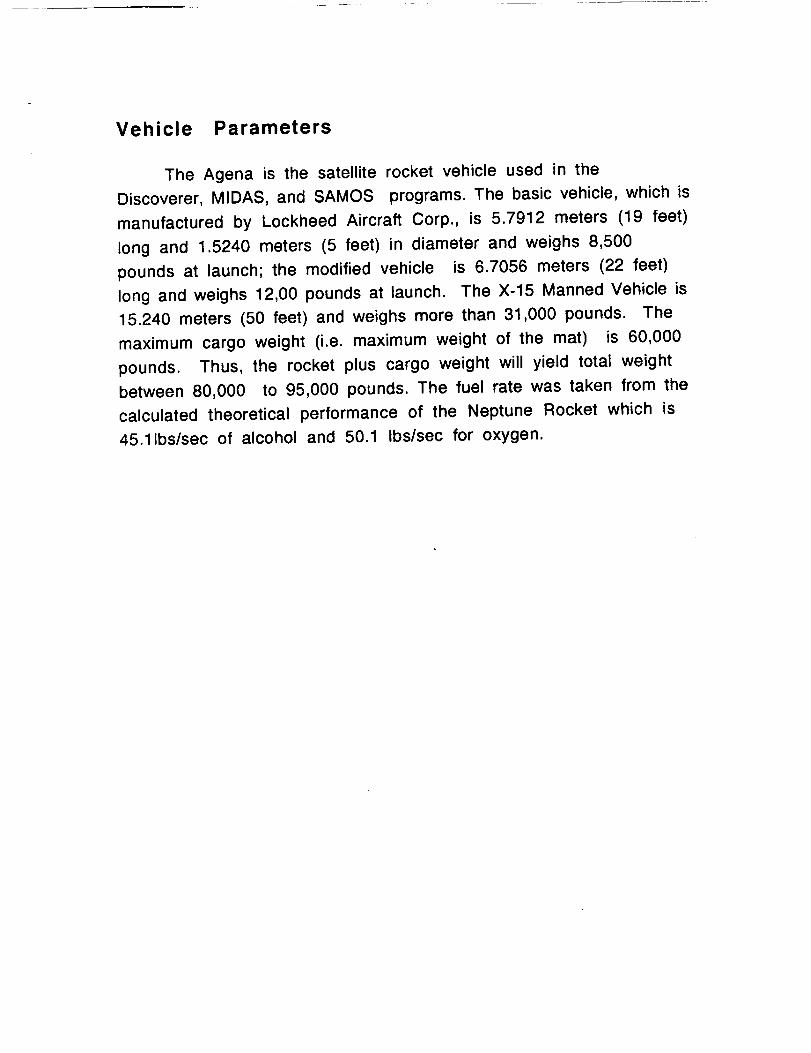
Vehicle Parameters
The Agena is the satellite rocket vehicle used in the
Discoverer, MIDAS, and SAMOS programs. The basic vehicle, which is
manufactured by Lockheed Aircraft Corp., is 5.7912 meters (19 feet)
long and 1.5240 meters (5 feet) in diameter and weighs 8,500
pounds at launch; the modified vehicle is 6.7056 meters (22 feet)
long and weighs 12,00 pounds at launch. The X-15 Manned Vehicle is
15.240 meters (50 feet) and weighs more than 31,000 pounds. The
maximum cargo weight (i.e. maximum weight of the mat) is 60,000
pounds. Thus, the rocket plus cargo weight will yield total weight
between 80,000 to 95,000 pounds. The fuel rate was taken from the
calculated theoretical performance of the Neptune Rocket which is
45.11bs/sec of alcohol and 50.1 Ibs/sec for oxygen.
Z<tmL0Z0m
I,,I.
<tfJ)<t1,1,,I0n-OIJ.D
D
i I
oJ
I ' I ' I ' I
0 00 (0,-: d d d
(M)-4 = 30uo-J
I
oJ
d0
0
00
0cO
0co
IZ,I,,=I
zo _
0oJ
0

I.i..0Z0
0Z
I.I..
¢n
I.U0n-OI.I.D
D
C3
I I I
CO OJ ':--
(M)-_ = 30UO-_
C)
C)C)
C)
C)¢C)
El.J
xo _
C)
C)

Appendix K
Fabric Characteristics
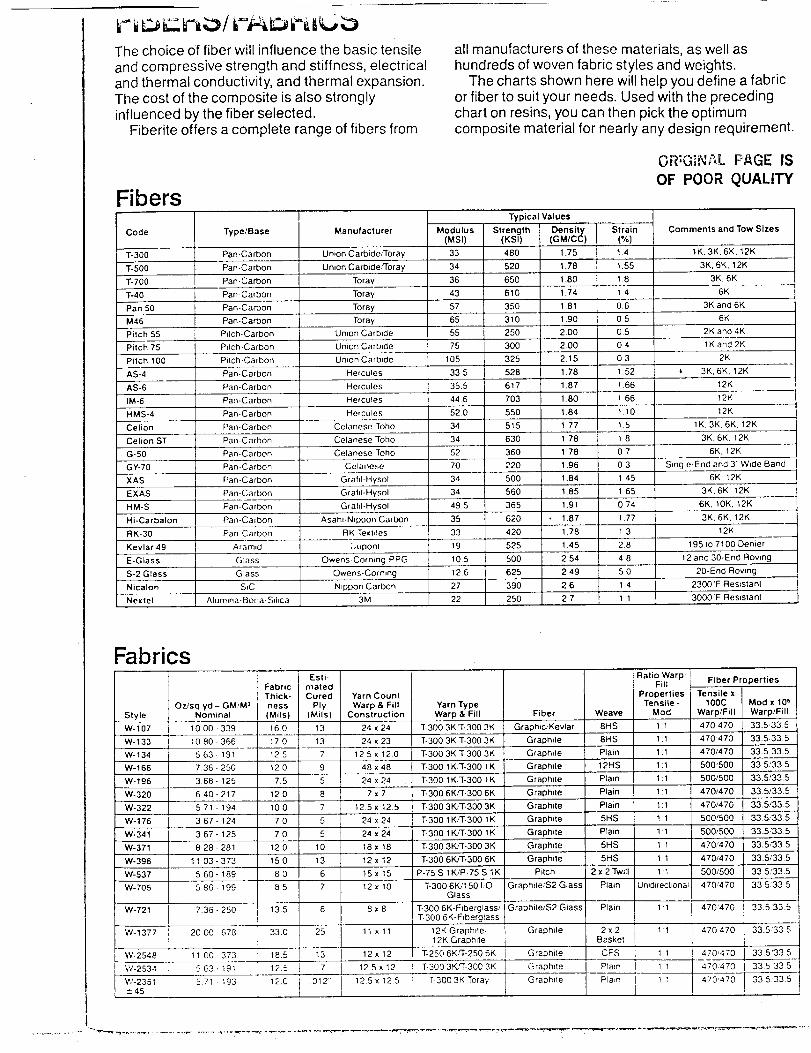
The choice of fiber will influence the basic tensileand compressive strength and stiffness, electricaland thermal conductivity, and thermal expansion.The cost of the composite is also stronglyinfluenced by the fiber selected.
Fiberite offers a complete range of fibers from
"ibers
all manufacturers of these materials, as well ashundreds of woven fabric styles and weights.
The charts shown here will help you define a fabricor fiber to suit your needs. Used with the precedingchart on resins, you can then pick the optimumcomposite material for nearly any design requirement.
0-m,";,_,Pd PAGE IS_¢l, %b.;li i _it .-
OF POOR QUALrrY
Code
T-300
%500
T-700
Type/Base
Pan-Carbon
Pan-Carbon
Pan-Carbon
Manufacturer
Union Carbide,'Toray
Union CarbideP'roray
Toray
Modulus
(MSI)
33
34
36
Typical Values
Strain
(%)1,4
1.55
18
Comments andTow Sizes
tK.3K, 6K. 12K
3K, 6K, 12K
3K. 6K
6KT-40 Pan-Carbon Toray 43 1 4
Pan 50 Pan-Carbon Toray 57 0.6 3K and 6K
M46 Pan-Carbon Toray 65 05 6K
Pitch 55 Pitch-Carbon Umon Carbide 55 0.5 2K and 4K
Pilch 75 Pitch-Carbon Union Carb,3e 75 04 1K and 2K
Pilch 100 Pitch-Carbon Unnon Carbide 105 0.3 2K
AS-4 Pan-Carbon Hercules 335 1 52 l 3K, 6K. 12K
AS-6 Pan-Carbon Hercules 35.5 1 66 12K
IM-6 Pan-Carbon Hercules 446 1 66 12K
HMS-4 Pan-Carbon Her cules 520 1 10 12K
34
34
Celanese Toho
Celanese Toho
Strength Density(KSI) (GM/CC)
480 1.75
520 1.78
650 1.80
610 1.74
350 181
310 1.90
250 2.00
300 2.00
325 2.15
528 1.78
617 1.87
703 1.80
550 1.84
5t5 1.77
630 1 78
360 178
220 1.96
500 1.84
560 185
365 1.91
620 1.87
420 178
525 1.45
500 2 54
625 2 49
390 2.6
250 2.7
Celion
Celion ST
15
1.8
Pan-Carbon
Pan-Carbon
1K, 3K,6K, 12K
3K, 6K, 12K
6K. 12KG-50 Pan-Carbon Celanese Toho 52 07
GY-70 Pan-Carbon Celanese 70 03 Single-End and 3"' Wide Band
XAS Pan-Carbon GrahI-Hysol 34 1 45 6K. 12K
EXAS Pan-Carbon GrahI-Hysol 34 1 65 3K. 6K 12K
HM-S Pan-Carbon Grahl-Hysol 49 5 0 74 6K. 10K. 12K
Hi-Carbalon Pan-Carbon Asah=-N_ppon Carbon J 35 177 3K, 6K. 12K
RK.30 Pan-Carbon RK Te_(hles ] 33 1 3 12K
Kevlar 49 Aram_d L,uponl } 19 28 195 to 7100 Denier
E-GLass Glass Owens-Coming PPG 105 4 8 12 and 30-End Rowng
S-2 Glass Glass Owens-Cornmg 126 50 20-End Roving
Nicalon S_C Ntppon Carbon 27 1 4 2300"F Res_stanl
Nextel Alumma-Bona-Sd_ca 3M 22 1 1 3000' F Resistant
Fabrics
Style
W-107
W-133
OzJsq yd - GMtM_Nominal
I 10 00+339
i lO 80-366W-134 I 5 63-191
W-166 7 36-250
W-196 3.68-125
W-320 640-217
W-322 571-194
W-176 367-124
W-341 367-125
W-371 " 828-281
W-398 1103-373
W-537 5 60-t89
W-705 5 86-199
W-721 7.36-250
W-1377 i 2000-678
W-2548 ! 11 00-3732
J
W-2534 I 563-19t
W-2351 ! 5.71-193±45: !
Esti-Fabric matedThick- Cured
ness Ply(Mils) (Mils)
160 13
170 13
125 7
120 9
7.5 5
120 8
100 7
70 5
7O 5
12.0 10
150 13
80 6
85 7
13.5 8
33.0 25
18.5 13 i
125 7 t
120 012" II
Yarn Count
Warp & FillConstruction
Yarn TypeWarp & Fill Fiber
24 x 24 T-300 3K rT-300 3K Graphic Kevlar
24 x 23 ]'-300 3K 3"-300 3K Graphile
12 5 x 12 0 T-300 3K "I'-300 3K Graphite
48 x 48 T-300 1K,'l'-300 1K Graphite
24 x 24 ]--300 1K;T-300 1K Graphite
7 x 7 "I-300 6K/T-300 6K Graphite
12 5 x 12 5 "I-300 3K,'T-300 3K Graphite
24 x 24 ]-300 1KFF-300 1K Graphite
24 x 24 T-300 1K,'T-300 1K Graphite
18 x 18 T-300 3KFI'-300 3K Graphite
12 x 12 ]'-300 6K/T-300 6K Graphile
15x15 P.75 S tK/P-75 S 1K Pilch
12 x 10 ]'-300 6K/150 I,O Graphite_S2 GlassGlass
8 x 8 "]'-300 6K-Fiberglass,, GraphiteJS2 Glass
T-300 6K-Fiberglass
11 x 11 12K Graphtte] Graphite12K Graphite
12x12 T-250 6KFr-250 6K I Graphite
125x12
125x125
i T-300 3KFr-300 3K
T-300 3K Toray
Weave
8HS
8HS
Plain
12HS
Ptam
Plain
Plain
5HS
Plain
5HS
5HS
2 x 2 Twill
Piain
Plain
2x2Basket
CFS
Graphite Ptam
Graphite Plain
Ratio Warp/Fill
PropertiesTensile -
Mod
1:1
1:1
1:1
1:1
1:1
1:1
1:1
1:1
1:1
1:1
1:1
1:1
Unidirectional:
1:1
1:1
1:1
l 11
I t:1
J
Fiber Properties
Tensile x100C Mod x 106
Warp/Fill Warp/Fill
470 470 33.5335
470'470 33.5,,335
470/470 33.5 33 5
500'500 33.5/33 5
500/500 33.5'33 5
470/470 335/335
4701470 33.5/33.5
500/500 335/335
500_500 335,335
470,'470 33.5,'33 5
470/470 33.5;33 5
500,'500 335'335
470,'470 33 5'335
470'470 33 5'33 5
470 470 33.5'335
470'470 33 5'33 5
470470 335335
470'470 33 5335
Appendix L
Fabric Samples
Appendix M
Glossary
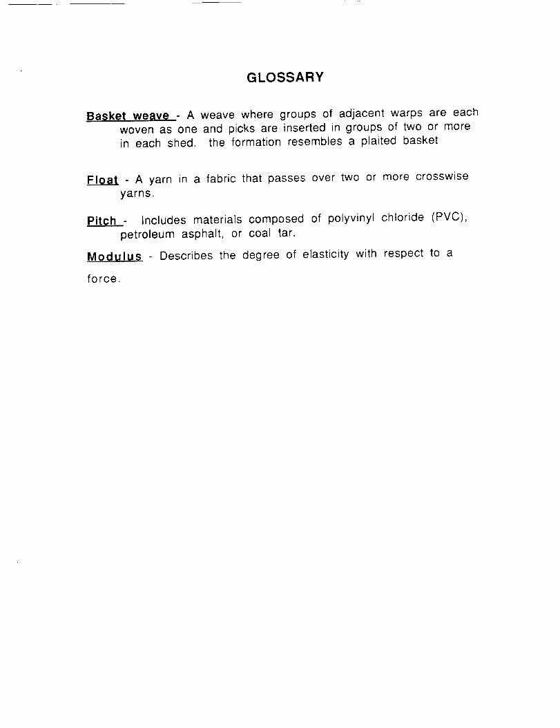
GLOSSARY
Basket weave A weave where groups of adjacent warps are each
woven as one and picks are inserted in groups of two or morein each shed. the formation resembles a plaited basket
Float - A yarn in a fabric that passes over two or more crosswise
yarns.
Pitch - Includes materials composed of polyvinyl chloride (PVC),
petroleum asphalt, or coal tar.
Modulus - Describes the degree of elasticity with respect to a
force.
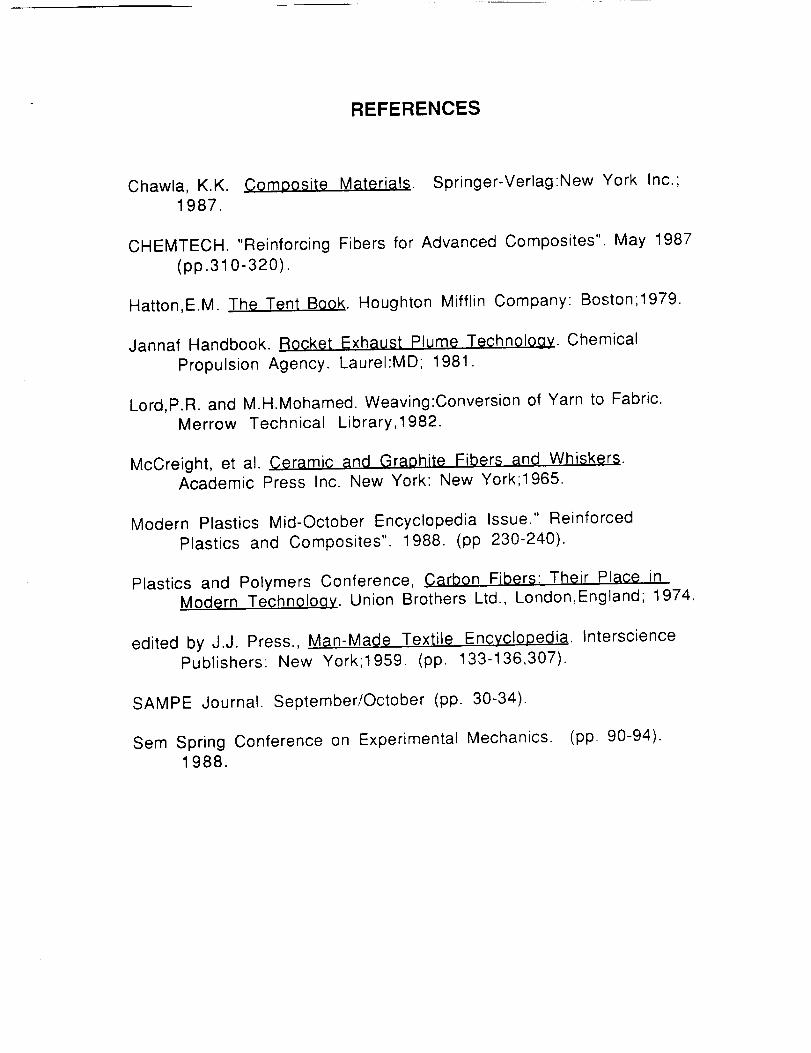
REFERENCES
Chawla, K.K. Composite Materials. Springer-Verlag:New York Inc.;1987.
CHEMTECH. "Reinforcing Fibers for Advanced Composites". May 1987
(pp.310-320).
Hatton,E.M. The Tent Book. Houghton Mifflin Company: Boston;1979.
Jannaf Handbook. Rocket Exhaust Plume Technology. Chemical
Propulsion Agency. Laurel:MD; 1981.
Lord,P.R. and M.H.Mohamed. Weaving:Conversion of Yarn to Fabric.
Merrow Technical Library,1982.
McCreight, et al. Ceramic and Graohite Fibers and Whiskers.Academic Press Inc. New York: New York;1965.
Modern Plastics Mid-October Encyclopedia Issue." ReinforcedPlastics and Composites". 1988. (pp 230-240).
Plastics and Polymers Conference, Carbon Fibers: Their Place in
Modern Technology. Union Brothers Ltd., London,England; 1974.
edited by J.J. Press., Man-Made Textile Encyclopedia. Interscience
Publishers: New York;1959. (pp. 133-136,307).
SAMPE Journal. September/October (pp. 30-34).
Sem Spring Conference on Experimental Mechanics. (pp. 90-94).1988.
ACKNOWLEDG EMENTS
The ME 4182 an Tex 4312 design group, W70, would like to
acknowledge the following persons for their contributions to the
efforts of the group: Prashant Desai, Jordan L. Dorrity, and J.W.
Brazell.