texture mapping opengl and implementation details cs351-50 11.05.03
Post on 19-Dec-2015
245 views
TRANSCRIPT
Texture Mapping
OpenGl and Implementation Details
CS351-50
11.05.03
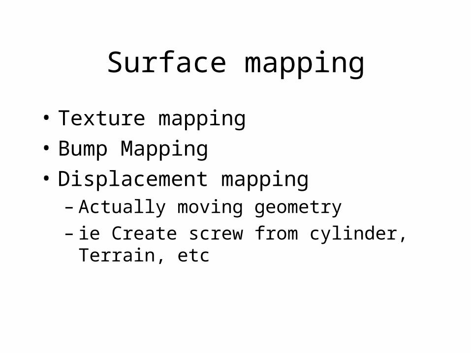
Surface mapping
• Texture mapping
• Bump Mapping
• Displacement mapping– Actually moving geometry– ie Create screw from cylinder, Terrain, etc
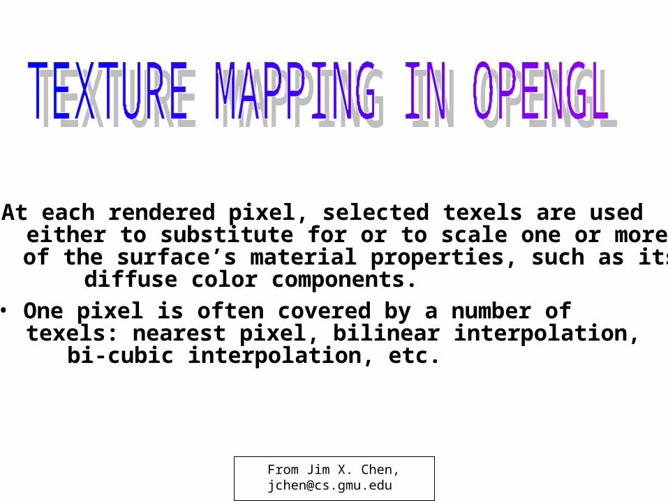
• At each rendered pixel, selected texels are used either to substitute for or to scale one or more of the surface’s material properties, such as its diffuse color components.
• One pixel is often covered by a number of texels: nearest pixel, bilinear interpolation, bi-cubic interpolation, etc.
From Jim X. Chen,[email protected]
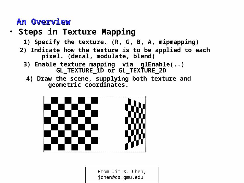
An OverviewAn Overview• Steps in Texture Mapping
1) Specify the texture. (R, G, B, A, mipmapping)2) Indicate how the texture is to be applied to each
pixel. (decal, modulate, blend)3) Enable texture mapping via glEnable(..)
GL_TEXTURE_1D or GL_TEXTURE_2D4) Draw the scene, supplying both texture and
geometric coordinates.
From Jim X. Chen,[email protected]
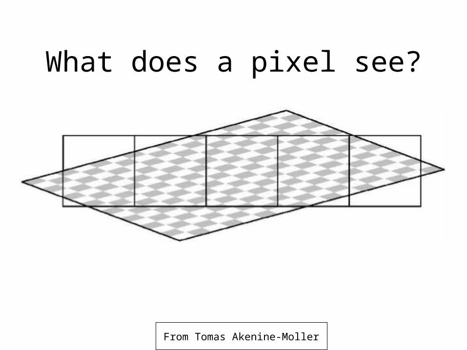
What does a pixel see?
From Tomas Akenine-Moller
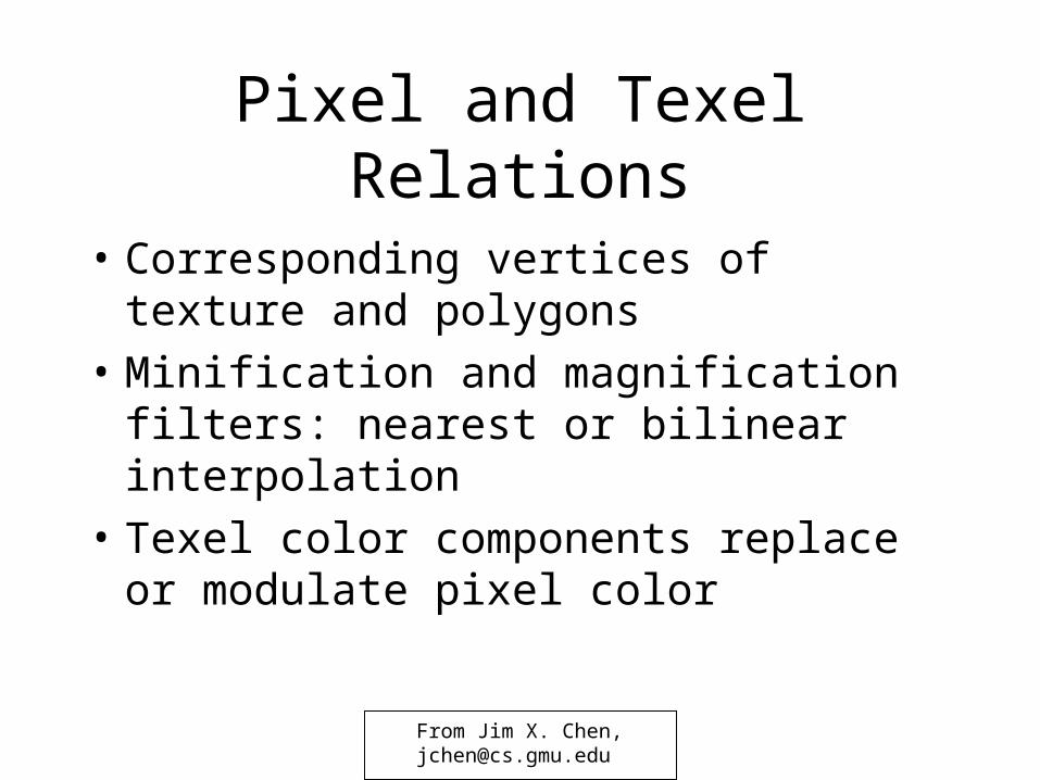
Pixel and Texel Relations
• Corresponding vertices of texture and polygons
• Minification and magnification filters: nearest or bilinear interpolation
• Texel color components replace or modulate pixel color
From Jim X. Chen,[email protected]
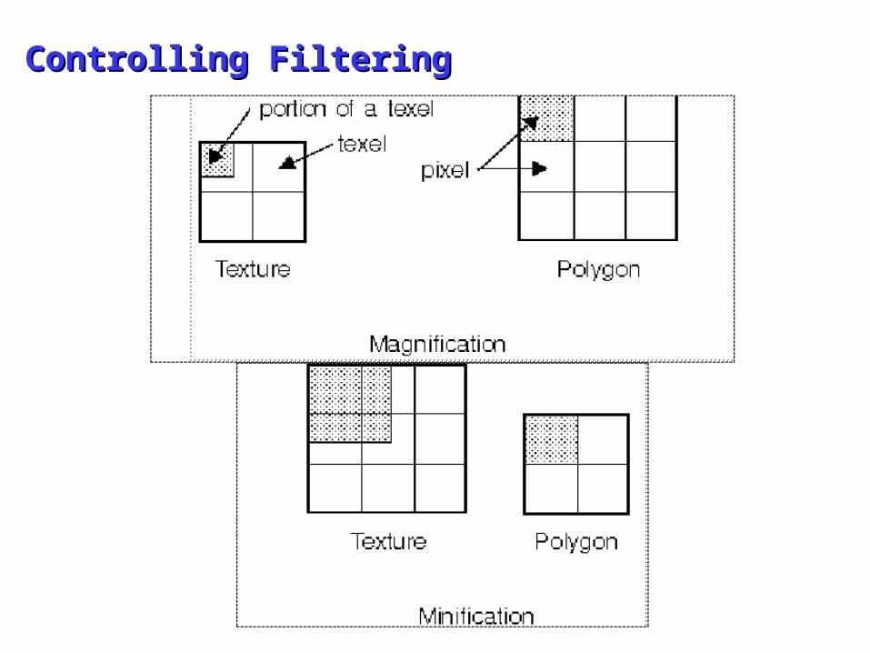
Controlling FilteringControlling Filtering
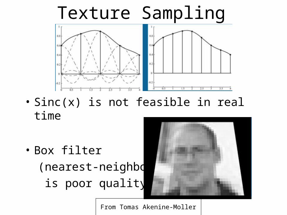
Texture Sampling
• Sinc(x) is not feasible in real time
• Box filter
(nearest-neighbor)
is poor quality
From Tomas Akenine-Moller
From Tomas Akenine-Moller
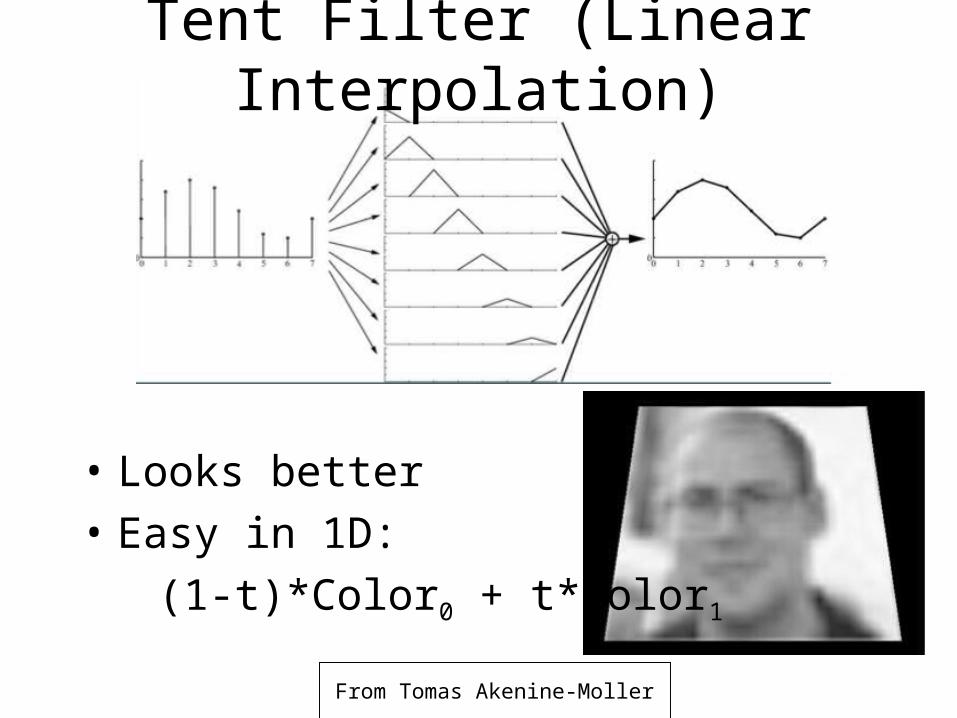
Tent Filter (Linear Interpolation)
• Looks better
• Easy in 1D:
(1-t)*Color0 + t*Color1
Interpolation
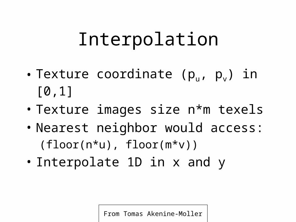
• Texture coordinate (pu, pv) in [0,1]
• Texture images size n*m texels
• Nearest neighbor would access:(floor(n*u), floor(m*v))
• Interpolate 1D in x and y
From Tomas Akenine-Moller
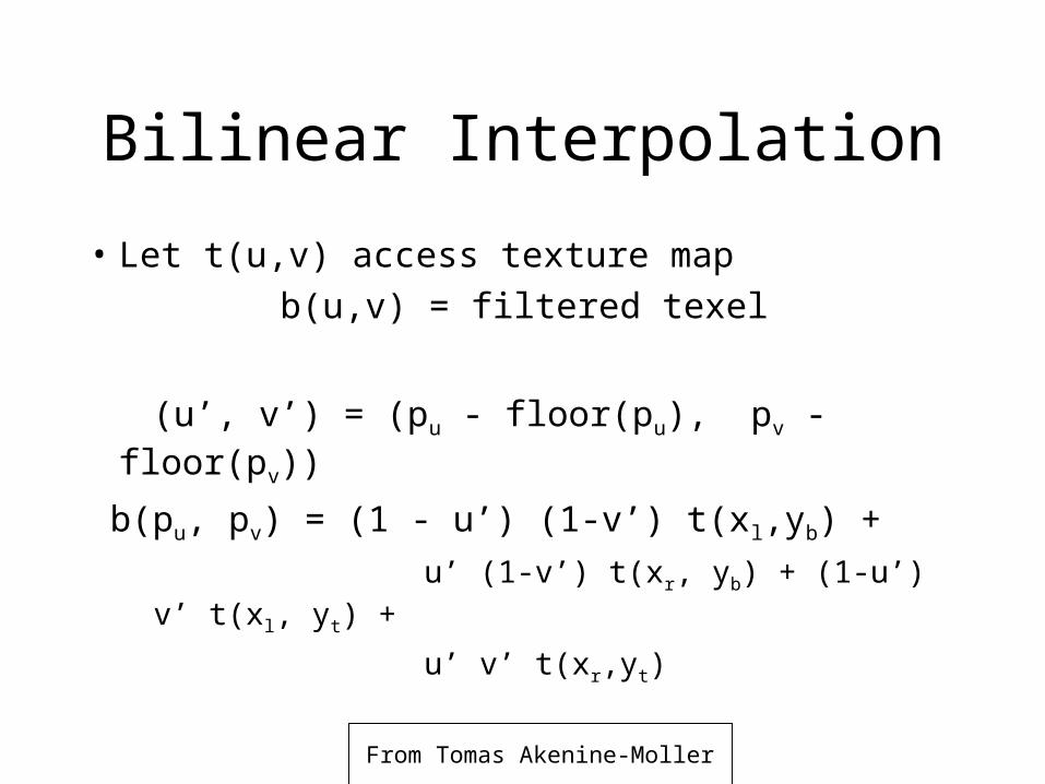
Bilinear Interpolation
• Let t(u,v) access texture map
b(u,v) = filtered texel
(u’, v’) = (pu - floor(pu), pv - floor(pv))
b(pu, pv) = (1 - u’) (1-v’) t(xl,yb) +
u’ (1-v’) t(xr, yb) + (1-u’) v’ t(xl, yt) +
u’ v’ t(xr,yt)
From Tomas Akenine-Moller
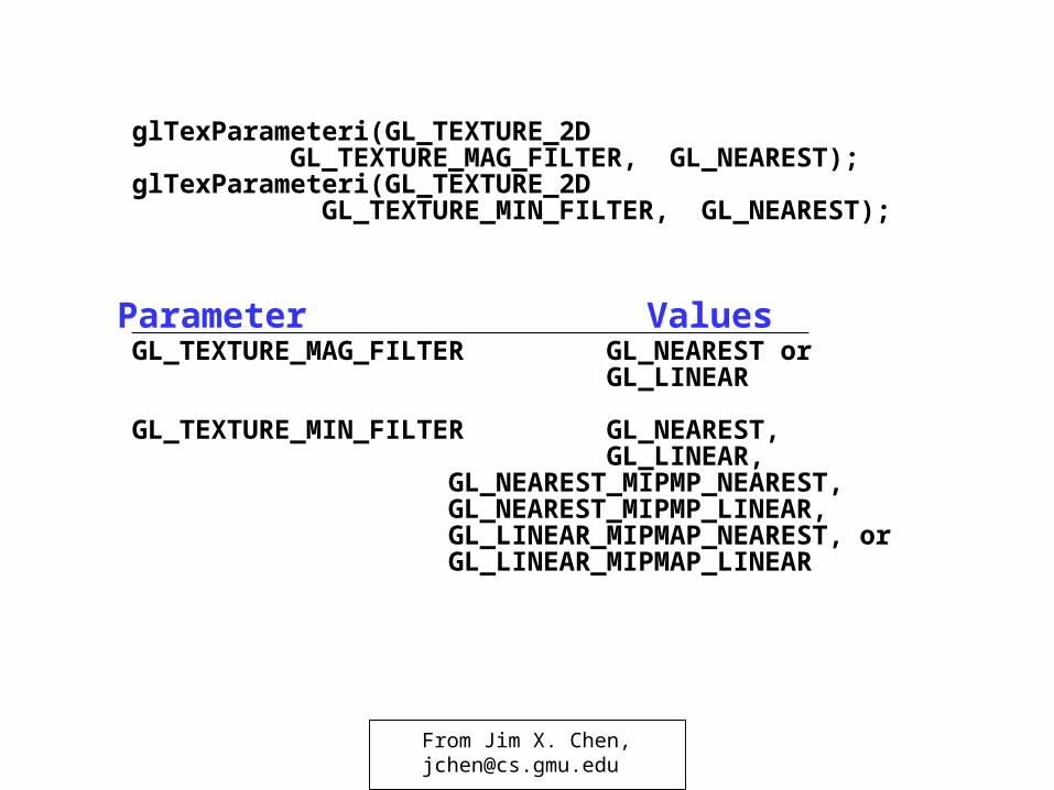
glTexParameteri(GL_TEXTURE_2D GL_TEXTURE_MAG_FILTER, GL_NEAREST);
glTexParameteri(GL_TEXTURE_2D GL_TEXTURE_MIN_FILTER, GL_NEAREST);
Parameter ValuesGL_TEXTURE_MAG_FILTER GL_NEAREST or
GL_LINEAR
GL_TEXTURE_MIN_FILTER GL_NEAREST,GL_LINEAR,
GL_NEAREST_MIPMP_NEAREST, GL_NEAREST_MIPMP_LINEAR, GL_LINEAR_MIPMAP_NEAREST, or GL_LINEAR_MIPMAP_LINEAR
From Jim X. Chen,[email protected]
From Tomas Akenine-Moller
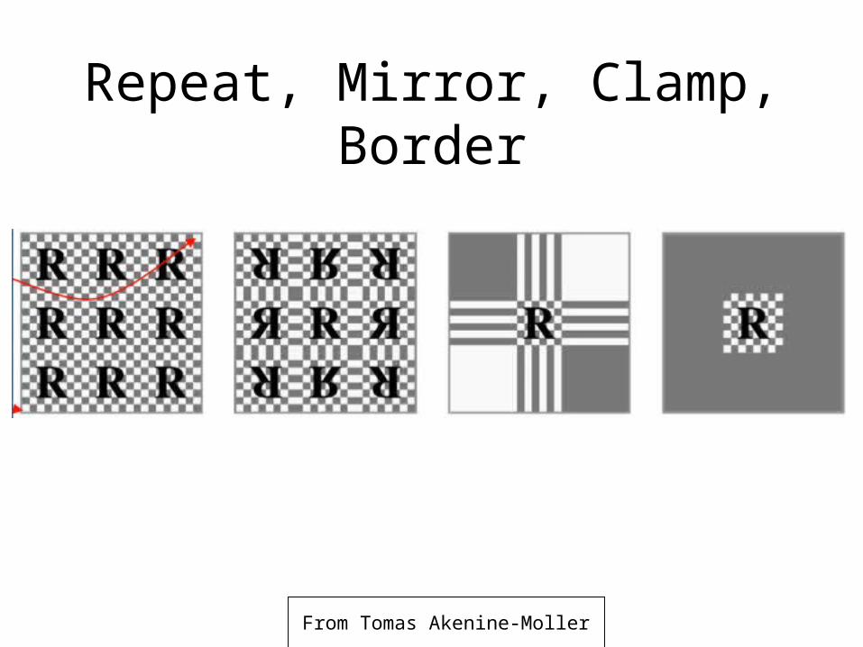
Repeat, Mirror, Clamp, Border
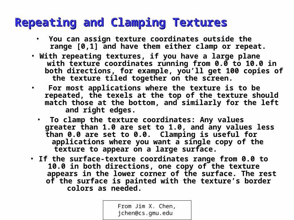
Repeating and Clamping TexturesRepeating and Clamping Textures• You can assign texture coordinates outside the
range [0,1] and have them either clamp or repeat. • With repeating textures, if you have a large plane
with texture coordinates running from 0.0 to 10.0 in both directions, for example, you’ll get 100 copies of the texture tiled together on the screen.
• For most applications where the texture is to be repeated, the texels at the top of the texture should match those at the bottom, and similarly for the left and right edges.
• To clamp the texture coordinates: Any values greater than 1.0 are set to 1.0, and any values less than 0.0 are set to 0.0. Clamping is useful for applications where you want a single copy of the texture to appear on a large surface.
• If the surface-texture coordinates range from 0.0 to 10.0 in both directions, one copy of the texture appears in the lower corner of the surface. The rest of the surface is painted with the texture’s border colors as needed.
From Jim X. Chen,[email protected]
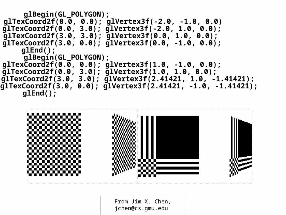
glBegin(GL_POLYGON); glTexCoord2f(0.0, 0.0); glVertex3f(-2.0, -1.0, 0.0) glTexCoord2f(0.0, 3.0); glVertex3f(-2.0, 1.0, 0.0); glTexCoord2f(3.0, 3.0); glVertex3f(0.0, 1.0, 0.0); glTexCoord2f(3.0, 0.0); glVertex3f(0.0, -1.0, 0.0); glEnd(); glBegin(GL_POLYGON); glTexCoord2f(0.0, 0.0); glVertex3f(1.0, -1.0, 0.0); glTexCoord2f(0.0, 3.0); glVertex3f(1.0, 1.0, 0.0); glTexCoord2f(3.0, 3.0); glVertex3f(2.41421, 1.0, -1.41421); glTexCoord2f(3.0, 0.0); glVertex3f(2.41421, -1.0, -1.41421); glEnd();
From Jim X. Chen,[email protected]
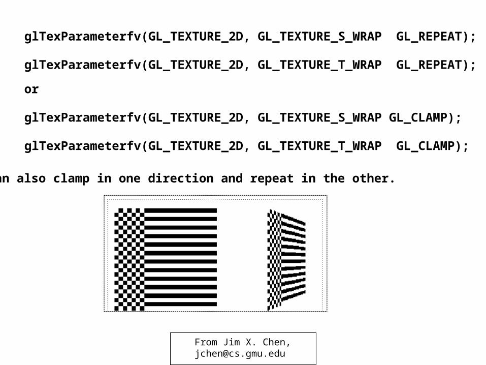
glTexParameterfv(GL_TEXTURE_2D, GL_TEXTURE_S_WRAP GL_REPEAT);
glTexParameterfv(GL_TEXTURE_2D, GL_TEXTURE_T_WRAP GL_REPEAT);
or
glTexParameterfv(GL_TEXTURE_2D, GL_TEXTURE_S_WRAP GL_CLAMP);
glTexParameterfv(GL_TEXTURE_2D, GL_TEXTURE_T_WRAP GL_CLAMP);
You can also clamp in one direction and repeat in the other.
From Jim X. Chen,[email protected]
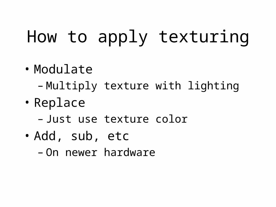
How to apply texturing
• Modulate– Multiply texture with lighting
• Replace– Just use texture color
• Add, sub, etc – On newer hardware
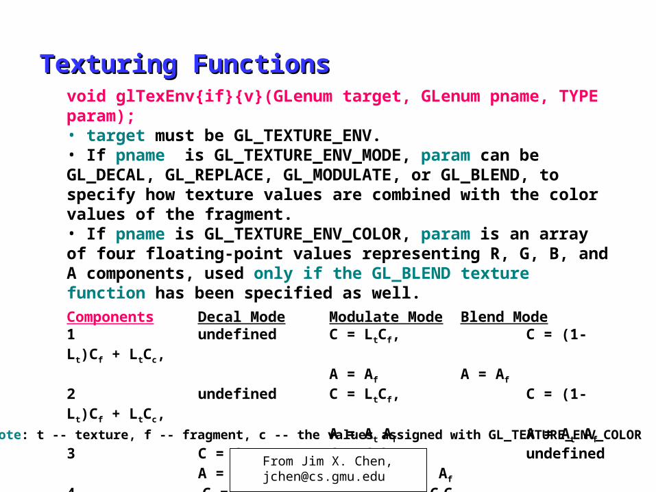
Texturing FunctionsTexturing Functionsvoid glTexEnv{if}{v}(GLenum target, GLenum pname, TYPE param); • target must be GL_TEXTURE_ENV. • If pname is GL_TEXTURE_ENV_MODE, param can be GL_DECAL, GL_REPLACE, GL_MODULATE, or GL_BLEND, to specify how texture values are combined with the color values of the fragment. • If pname is GL_TEXTURE_ENV_COLOR, param is an array of four floating-point values representing R, G, B, and A components, used only if the GL_BLEND texture function has been specified as well.
Components Decal Mode Modulate Mode Blend Mode1 undefined C = LtCf, C = (1-Lt)Cf + LtCc,
A = Af A = Af
2 undefined C = LtCf, C = (1-Lt)Cf + LtCc,A = At Af A = At Af
3 C = Ct C = CtCf , undefinedA = Af A = Af
4 C = (1-At)Cf + AtCt, C = CtCf , undefinedA = Af A = AtAfNote: t -- texture, f -- fragment, c -- the values assigned with GL_TEXTURE_ENV_COLOR
From Jim X. Chen,[email protected]
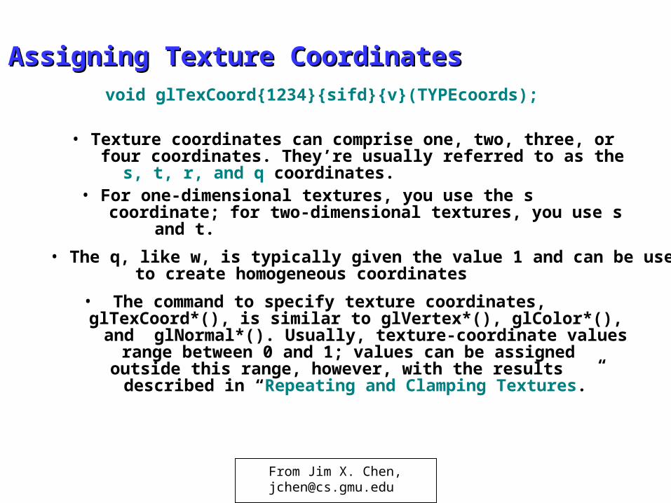
Assigning Texture CoordinatesAssigning Texture Coordinates
• Texture coordinates can comprise one, two, three, or four coordinates. They’re usually referred to as the s, t, r, and q coordinates.
• For one-dimensional textures, you use the s coordinate; for two-dimensional textures, you use s and t.
• The q, like w, is typically given the value 1 and can be used to create homogeneous coordinates
• The command to specify texture coordinates, glTexCoord*(), is similar to glVertex*(), glColor*(), and glNormal*(). Usually, texture-coordinate values range between 0 and 1; values can be assigned outside this range, however, with the results described in “Repeating and Clamping Textures.”
void glTexCoord{1234}{sifd}{v}(TYPEcoords);
From Jim X. Chen,[email protected]
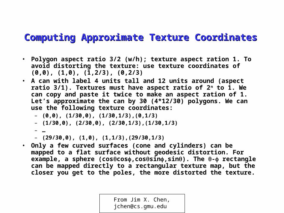
Computing Approximate Texture CoordinatesComputing Approximate Texture Coordinates
• Polygon aspect ratio 3/2 (w/h); texture aspect ration 1. To avoid distorting the texture: use texture coordinates of (0,0), (1,0), (1,2/3), (0,2/3)
• A can with label 4 units tall and 12 units around (aspect ratio 3/1). Textures must have aspect ratio of 2n to 1. We can copy and paste it twice to make an aspect ration of 1. Let’s approximate the can by 30 (4*12/30) polygons. We can use the following texture coordinates:– (0,0), (1/30,0), (1/30,1/3),(0,1/3)– (1/30,0), (2/30,0), (2/30,1/3),(1/30,1/3)– …– (29/30,0), (1,0), (1,1/3),(29/30,1/3)
• Only a few curved surfaces (cone and cylinders) can be mapped to a flat surface without geodesic distortion. For example, a sphere (coscos,cossin,sin). The - rectangle can be mapped directly to a rectangular texture map, but the closer you get to the poles, the more distorted the texture.
From Jim X. Chen,[email protected]
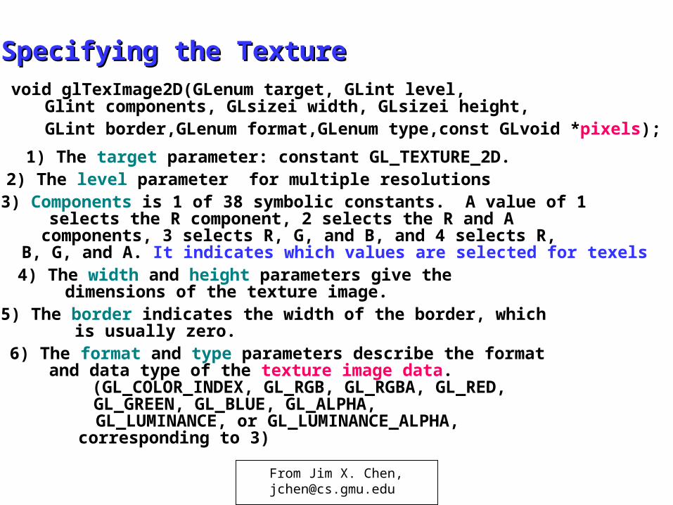
Specifying the TextureSpecifying the Texturevoid glTexImage2D(GLenum target, GLint level,
Glint components, GLsizei width, GLsizei height, GLint border,GLenum format,GLenum type,const GLvoid *pixels);
1) The target parameter: constant GL_TEXTURE_2D. 2) The level parameter for multiple resolutions3) Components is 1 of 38 symbolic constants. A value of 1
selects the R component, 2 selects the R and A components, 3 selects R, G, and B, and 4 selects R, B, G, and A. It indicates which values are selected for texels
4) The width and height parameters give the dimensions of the texture image.
5) The border indicates the width of the border, which is usually zero.
6) The format and type parameters describe the format and data type of the texture image data. (GL_COLOR_INDEX, GL_RGB, GL_RGBA, GL_RED, GL_GREEN, GL_BLUE, GL_ALPHA, GL_LUMINANCE, or GL_LUMINANCE_ALPHA, corresponding to 3)
From Jim X. Chen,[email protected]
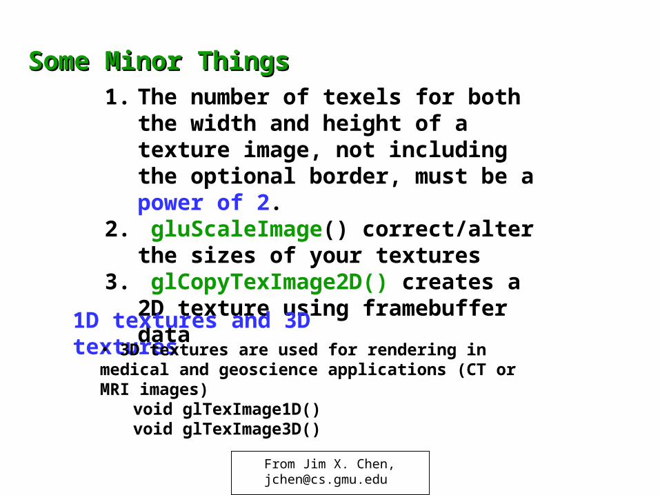
1. The number of texels for both the width and height of a texture image, not including the optional border, must be a power of 2.
2. gluScaleImage() correct/alter the sizes of your textures
3. glCopyTexImage2D() creates a 2D texture using framebuffer data
1D textures and 3D textures• 3D textures are used for rendering in medical and geoscience applications (CT or MRI images)
void glTexImage1D()void glTexImage3D()
Some Minor ThingsSome Minor Things
From Jim X. Chen,[email protected]
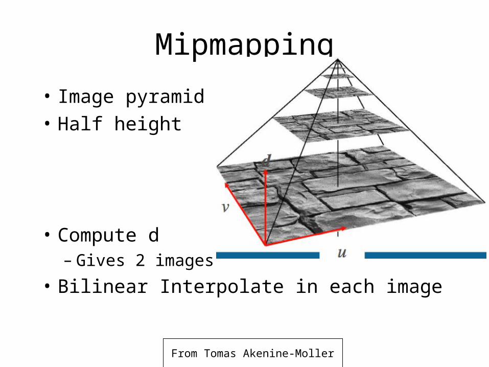
Mipmapping
• Image pyramid• Half height and
width
• Compute d– Gives 2 images
• Bilinear Interpolate in each image
From Tomas Akenine-Moller
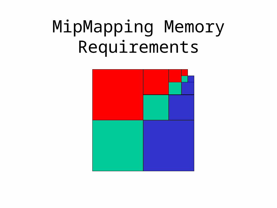
MipMapping Memory Requirements
Multiple Levels of DetailMultiple Levels of Detail
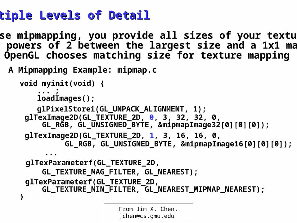
• To use mipmapping, you provide all sizes of your texture in powers of 2 between the largest size and a 1x1 map. OpenGL chooses matching size for texture mapping
A Mipmapping Example: mipmap.c
void myinit(void) { ... ; loadImages(); glPixelStorei(GL_UNPACK_ALIGNMENT, 1);glTexImage2D(GL_TEXTURE_2D, 0, 3, 32, 32, 0,
GL_RGB, GL_UNSIGNED_BYTE, &mipmapImage32[0][0][0]); glTexImage2D(GL_TEXTURE_2D, 1, 3, 16, 16, 0, GL_RGB, GL_UNSIGNED_BYTE, &mipmapImage16[0][0][0]);
...glTexParameterf(GL_TEXTURE_2D,
GL_TEXTURE_MAG_FILTER, GL_NEAREST);glTexParameterf(GL_TEXTURE_2D,
GL_TEXTURE_MIN_FILTER, GL_NEAREST_MIPMAP_NEAREST);}
From Jim X. Chen,[email protected]
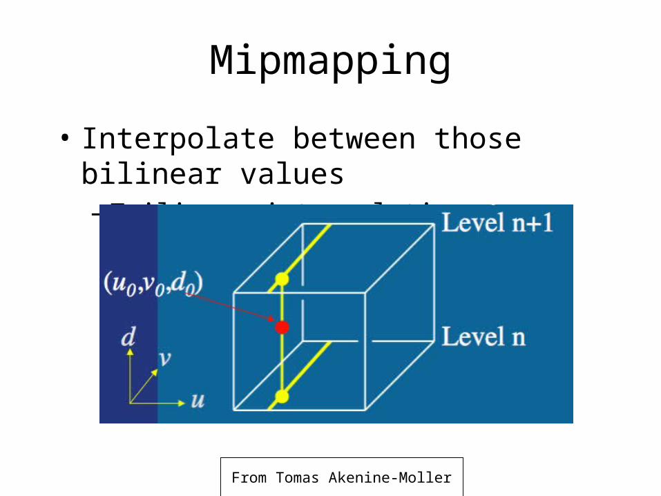
Mipmapping
• Interpolate between those bilinear values– Trilinear interpolation
From Tomas Akenine-Moller
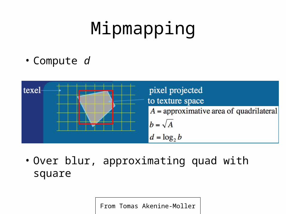
Mipmapping
• Compute d
• Over blur, approximating quad with square
From Tomas Akenine-Moller
From Tomas Akenine-Moller
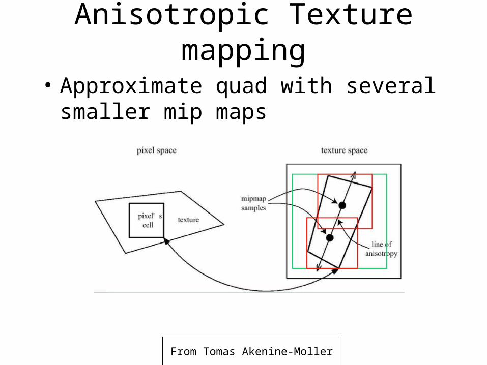
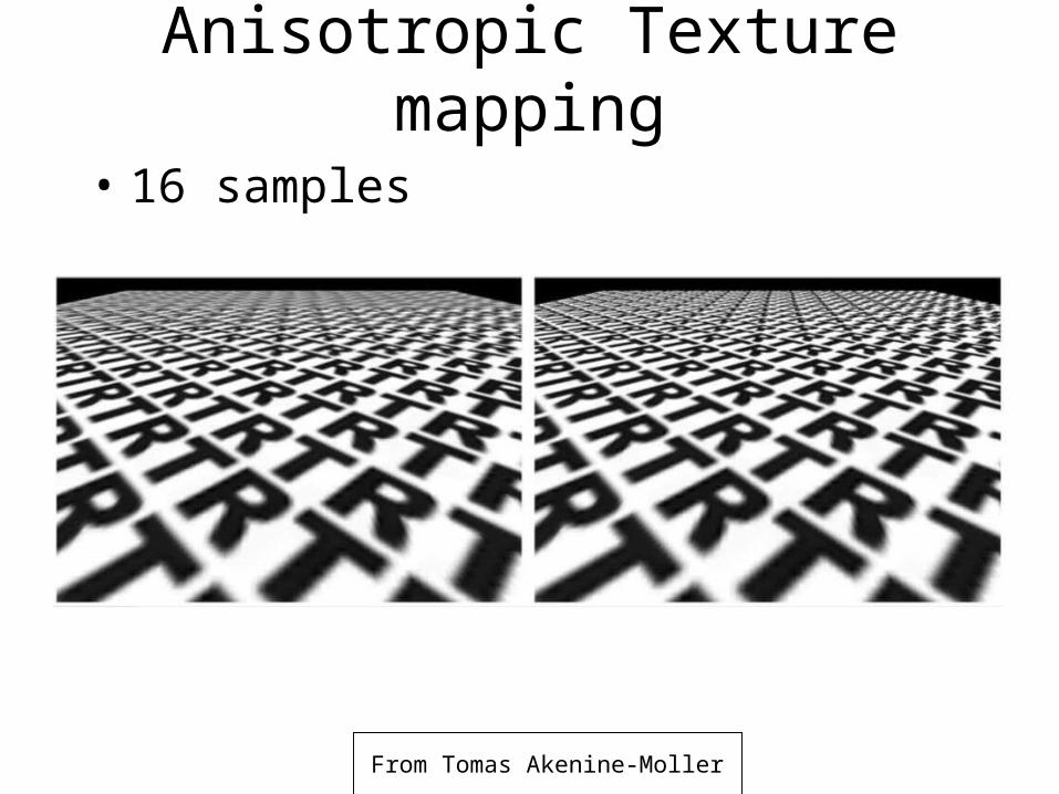
Anisotropic Texture mapping
• Approximate quad with several smaller mip maps
From Tomas Akenine-Moller
Anisotropic Texture mapping
• 16 samples
Demo
• Nate Robins Texture Mapping Tutor
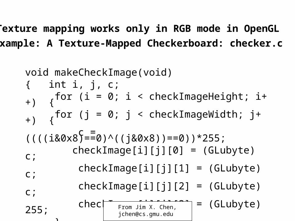
• Texture mapping works only in RGB mode in OpenGL
• Example: A Texture-Mapped Checkerboard: checker.c
void makeCheckImage(void){ int i, j, c; for (i = 0; i < checkImageHeight; i++) { for (j = 0; j < checkImageWidth; j++) { c = ((((i&0x8)==0)^((j&0x8))==0))*255; checkImage[i][j][0] = (GLubyte) c; checkImage[i][j][1] = (GLubyte) c; checkImage[i][j][2] = (GLubyte) c; checkImage[i][j][3] = (GLubyte) 255; } }} From Jim X. Chen,
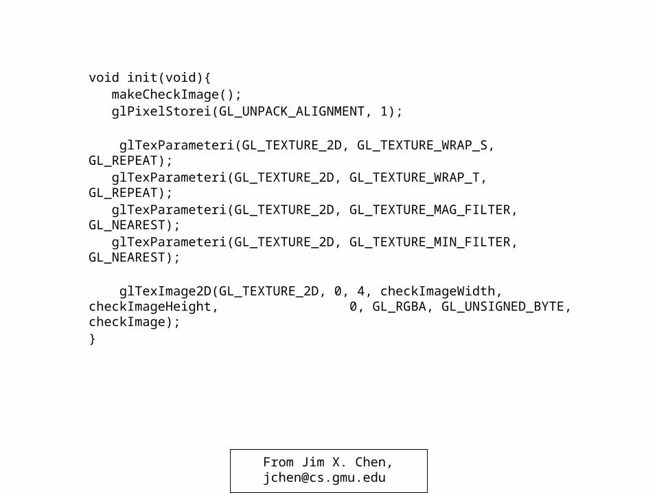
void init(void){ makeCheckImage(); glPixelStorei(GL_UNPACK_ALIGNMENT, 1);
glTexParameteri(GL_TEXTURE_2D, GL_TEXTURE_WRAP_S, GL_REPEAT); glTexParameteri(GL_TEXTURE_2D, GL_TEXTURE_WRAP_T, GL_REPEAT); glTexParameteri(GL_TEXTURE_2D, GL_TEXTURE_MAG_FILTER, GL_NEAREST); glTexParameteri(GL_TEXTURE_2D, GL_TEXTURE_MIN_FILTER, GL_NEAREST);
glTexImage2D(GL_TEXTURE_2D, 0, 4, checkImageWidth, checkImageHeight, 0, GL_RGBA, GL_UNSIGNED_BYTE, checkImage);}
From Jim X. Chen,[email protected]
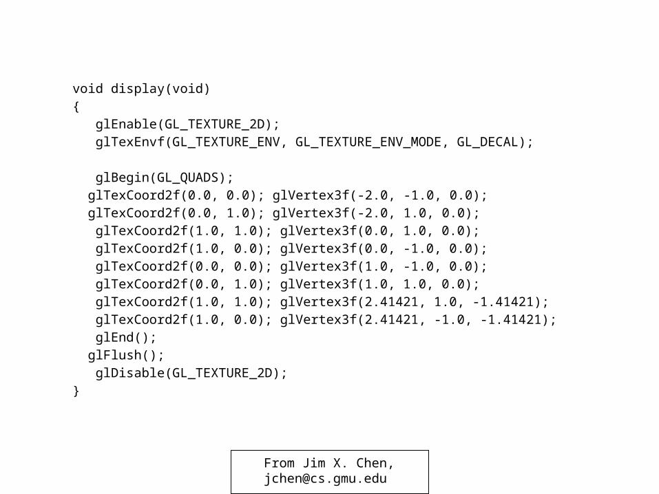
void display(void)
{
glEnable(GL_TEXTURE_2D);
glTexEnvf(GL_TEXTURE_ENV, GL_TEXTURE_ENV_MODE, GL_DECAL);
glBegin(GL_QUADS);
glTexCoord2f(0.0, 0.0); glVertex3f(-2.0, -1.0, 0.0);
glTexCoord2f(0.0, 1.0); glVertex3f(-2.0, 1.0, 0.0);
glTexCoord2f(1.0, 1.0); glVertex3f(0.0, 1.0, 0.0);
glTexCoord2f(1.0, 0.0); glVertex3f(0.0, -1.0, 0.0);
glTexCoord2f(0.0, 0.0); glVertex3f(1.0, -1.0, 0.0);
glTexCoord2f(0.0, 1.0); glVertex3f(1.0, 1.0, 0.0);
glTexCoord2f(1.0, 1.0); glVertex3f(2.41421, 1.0, -1.41421);
glTexCoord2f(1.0, 0.0); glVertex3f(2.41421, -1.0, -1.41421);
glEnd();
glFlush();
glDisable(GL_TEXTURE_2D);
}
From Jim X. Chen,[email protected]
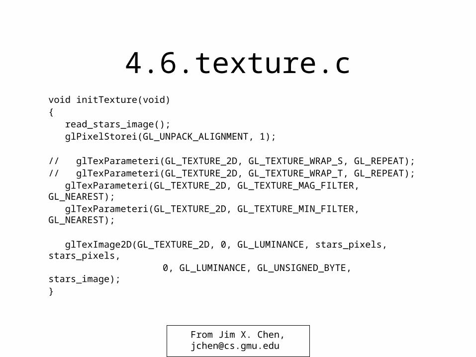
4.6.texture.cvoid initTexture(void){ read_stars_image(); glPixelStorei(GL_UNPACK_ALIGNMENT, 1);
// glTexParameteri(GL_TEXTURE_2D, GL_TEXTURE_WRAP_S, GL_REPEAT);// glTexParameteri(GL_TEXTURE_2D, GL_TEXTURE_WRAP_T, GL_REPEAT); glTexParameteri(GL_TEXTURE_2D, GL_TEXTURE_MAG_FILTER, GL_NEAREST); glTexParameteri(GL_TEXTURE_2D, GL_TEXTURE_MIN_FILTER, GL_NEAREST);
glTexImage2D(GL_TEXTURE_2D, 0, GL_LUMINANCE, stars_pixels, stars_pixels, 0, GL_LUMINANCE, GL_UNSIGNED_BYTE, stars_image);
}
From Jim X. Chen,[email protected]
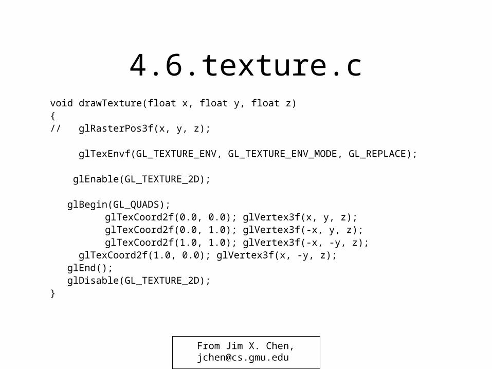
4.6.texture.cvoid drawTexture(float x, float y, float z){// glRasterPos3f(x, y, z);
glTexEnvf(GL_TEXTURE_ENV, GL_TEXTURE_ENV_MODE, GL_REPLACE); glEnable(GL_TEXTURE_2D);
glBegin(GL_QUADS); glTexCoord2f(0.0, 0.0); glVertex3f(x, y, z); glTexCoord2f(0.0, 1.0); glVertex3f(-x, y, z); glTexCoord2f(1.0, 1.0); glVertex3f(-x, -y, z);
glTexCoord2f(1.0, 0.0); glVertex3f(x, -y, z); glEnd(); glDisable(GL_TEXTURE_2D);}
From Jim X. Chen,[email protected]
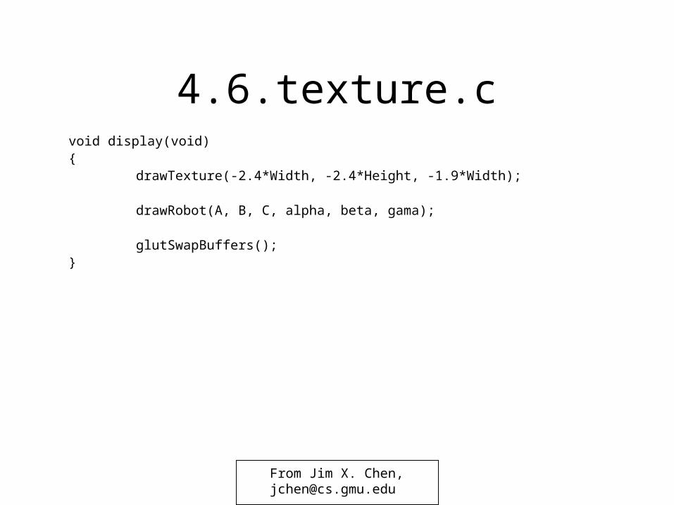
4.6.texture.cvoid display(void){
drawTexture(-2.4*Width, -2.4*Height, -1.9*Width);
drawRobot(A, B, C, alpha, beta, gama);
glutSwapBuffers(); }
From Jim X. Chen,[email protected]
Texture ObjectsTexture Objects
• Generate texture objects or names: glGenTextures()
• Initially bind texture objects to texture data, including the
image arrays and texture properties: glBindTexture()
• More often used objects stay in memory (prioritize the objects).
• Bind and rebind texture objects, making their data available for rendering texture models
• When we call glBindTexture() with a texture name, all subsequent glTex*() commands that specify the texture and its associated parameters are saved in the memory
From Jim X. Chen,[email protected]
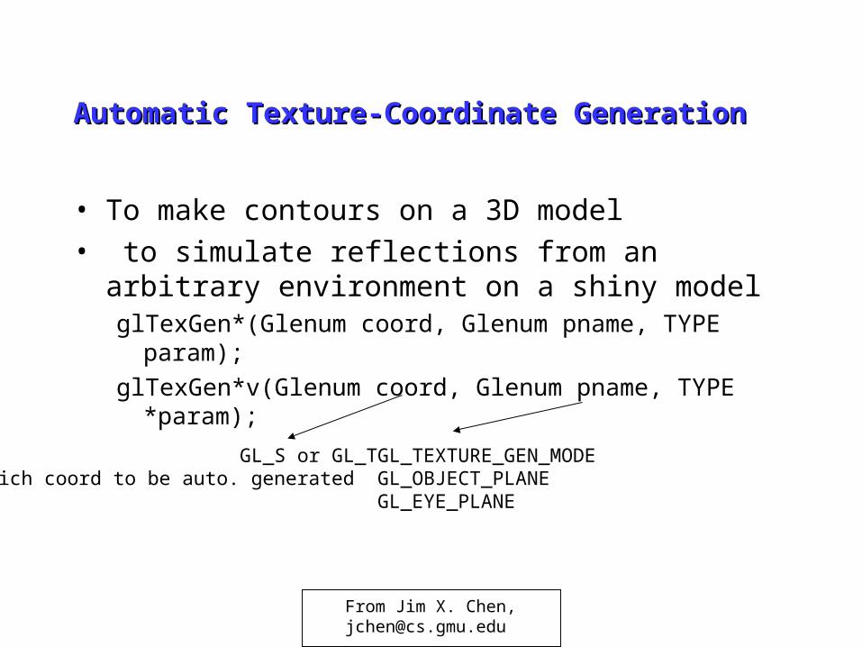
Automatic Texture-Coordinate GenerationAutomatic Texture-Coordinate Generation
• To make contours on a 3D model
• to simulate reflections from an arbitrary environment on a shiny modelglTexGen*(Glenum coord, Glenum pname, TYPE param);
glTexGen*v(Glenum coord, Glenum pname, TYPE *param);
GL_S or GL_TWhich coord to be auto. generated
GL_TEXTURE_GEN_MODEGL_OBJECT_PLANEGL_EYE_PLANE
From Jim X. Chen,[email protected]
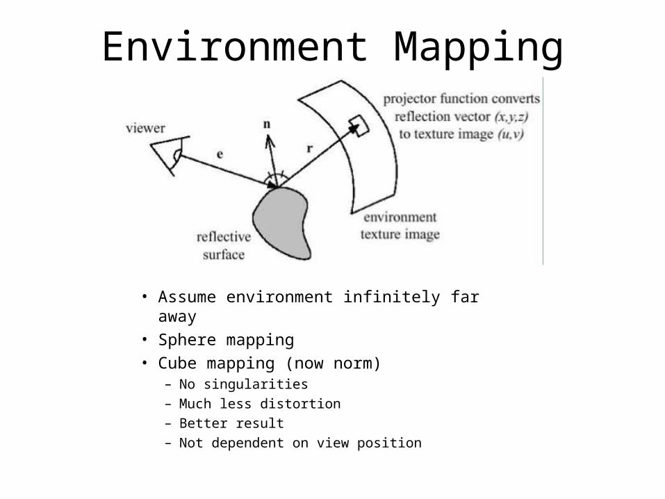
Environment Mapping
• Assume environment infinitely far away• Sphere mapping• Cube mapping (now norm)
– No singularities
– Much less distortion
– Better result
– Not dependent on view position
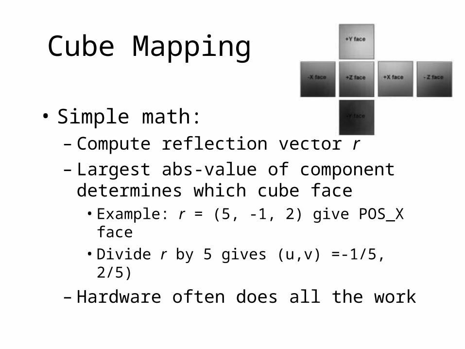
Cube Mapping
• Simple math:– Compute reflection vector r– Largest abs-value of component determines
which cube face• Example: r = (5, -1, 2) give POS_X face
• Divide r by 5 gives (u,v) =-1/5, 2/5)
– Hardware often does all the work
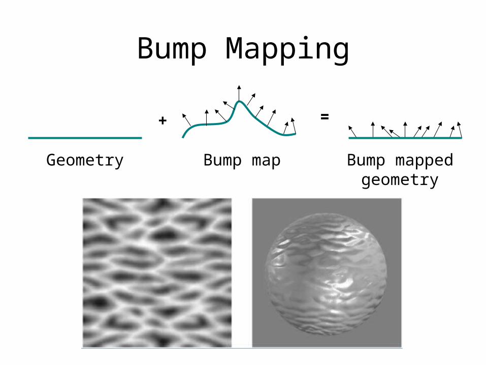
Bump Mapping
+ =
Geometry Bump map Bump mappedgeometry
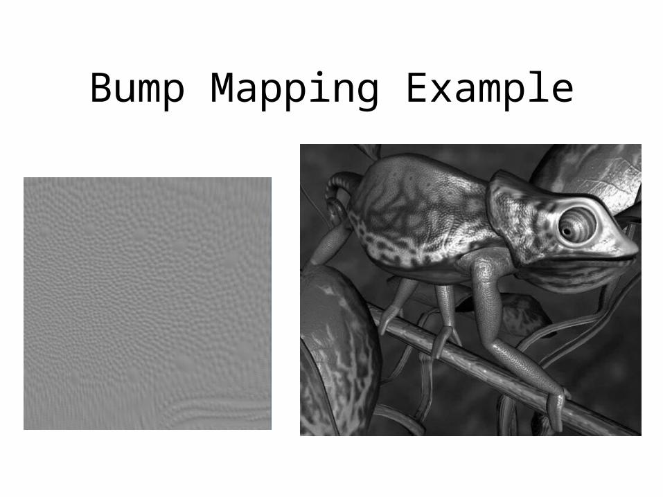
Bump Mapping Example
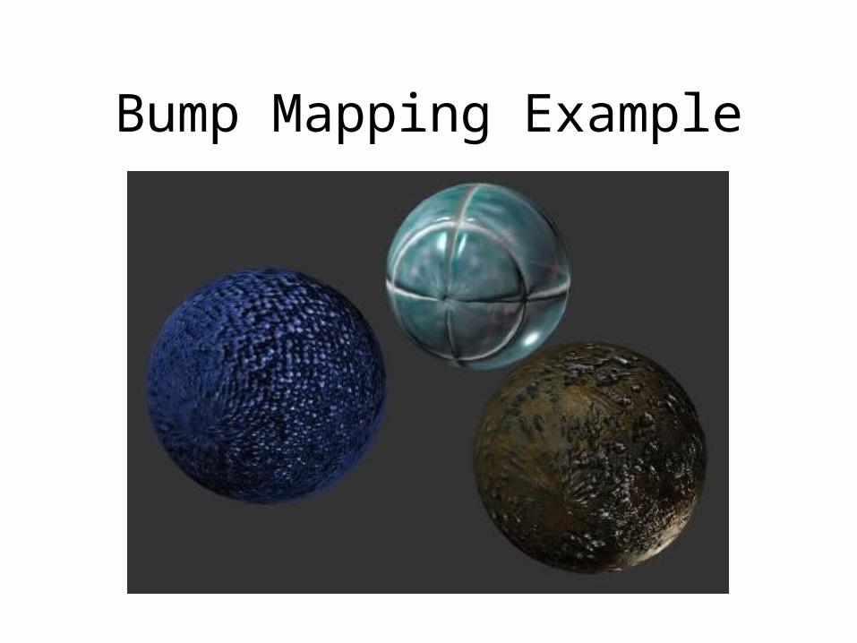
Bump Mapping Example
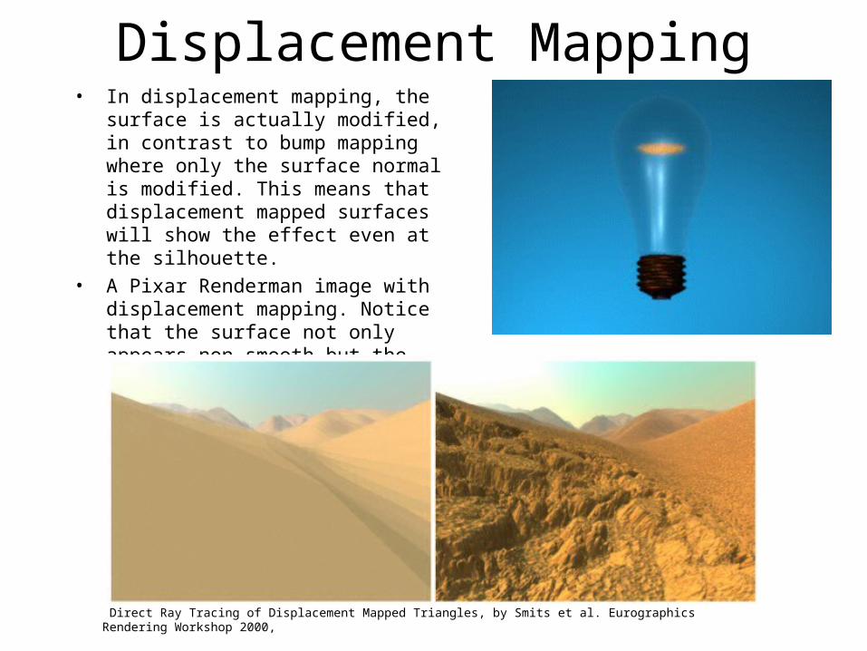
Displacement Mapping• In displacement mapping, the surface is
actually modified, in contrast to bump mapping where only the surface normal is modified. This means that displacement mapped surfaces will show the effect even at the silhouette.
• A Pixar Renderman image with displacement mapping. Notice that the surface not only appears non-smooth but the silhouette is also non-smooth.
Direct Ray Tracing of Displacement Mapped Triangles, by Smits et al. Eurographics Rendering Workshop 2000,