tfaws 2015 · tfaws 2015 . agenda •the ... •at gsfc, the instrumentation used to calculate the...
TRANSCRIPT
Thermal Coatings Seminar Series Training Part 1 : Properties of Thermal Coatings
August 6, 2015 1
NASA GSFC Contamination and Coatings Branch – Code 546
Hosted by: Jack Triolo - SGT, Inc.
TFAWS 2015

Agenda
• The Relationship of Coating Properties That We Can “Easily” Measure vs. the Properties We Need…ɑS & ɛH
• How Solar Absorptance is Determined • Description of Solar Reflectance measurement techniques
• Typical data
• How Thermal Hemispherical Emittance is Determined • Conversion of normal emittance to hemispherical emittance
• Emittance vs. temperature
• Description of measurement techniques
• Typical data
• Factors that Influence Thermal Radiative Properties
• BRDF – Specular and Diffuse
• GSFC Instruments Overview
• Types of Coatings Used at GSFC
August 6, 2015 2
Thermal Radiative Properties of Coatings
August 6, 2015 3
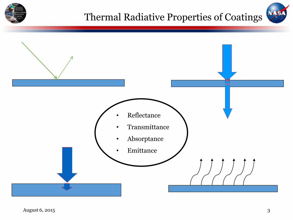
• Reflectance
• Transmittance
• Absorptance
• Emittance

Thermal Radiative Properties of Coatings
• Radiant energy is reflected, transmitted and/or absorbed by a surface or material
r + t + a = 1, for materials, where t = 0, r + a = 1, or a = 1- r
Where: Reflectance = r, Transmittance = t, and Absorptance = a
• Emittance (e) is the rate at which a body radiates energy (heat) at a given temperature in relation to the rate a black body radiator radiates energy (heat) at the same temperature
• Kirchhoff’s Law • Ideal radiator, when in thermal equilibrium, the body emits radiant energy at
the same rate at which it absorbs = e
• In the Aerospace Industry, a and e are never directly measured – THEY ARE CALCULATED!
August 6, 2015 4
(Information Obtained From Thermal Radiative Properties Coatings, Thermaphysical Properties of Matter, Volume 9)

Solar Absorptance Property Measurement
• At GSFC, the instrumentation used to calculate the solar absorptance measures over the spectral range of 250 to 2800 nanometers (.25 to 2.8 microns). An integrating sphere is used to measure the coating’s reflectance for the solar absorptance calculation
• Solar Absorptance is the total solar energy absorbed by the surface divided by the total solar energy integrated as a function of the wavelength
• Where R = reflectance, S = solar energy, as = solar absorptance, and l = wavelength
• The reflectance measurement is performed near-normal (angle of incidence = 15º). This measurement is typically sufficient for most surfaces up to approximately 45º
• Whereas, when measuring cylindrical surfaces, spherical surfaces or angle of incidence greater than 45º, variations in the angle of incidence will influence the solar absorptance value and must be measured
• Typically the Johnson curve is used to represent the total solar energy over the solar spectrum
August 6, 2015 5
s
1250
2800
R ( ) S ( ) d
250
2800
S ( ) d

Reflectance and the Johnson Curve
August 6, 2015 6
Johnson curve (blue) and the Polyrip clear/VDA (red)
Solar Absorptance value = .405

Directional Total Reflectivity
August 6, 2015 7
Incident Enegry
rd
rd
rd
rd
rs

Two Types of Integrating Spheres
August 6, 2015 8
Detector
sample
Reference
Edw ards Type Integrating Sphere
Incidence Angle
Reference Beam
Sample Beam
TransmittanceSample
Loc ation
Reference Beam
Sample BeamSample
Reference
TransmittanceSample
Loc ation
Detector
Four Port C omparsion Integrating Sphere

LPSR-300 Reflectometer Optical Schematic
August 6, 2015 9
115mm Integrating Sphere
2 Position Beam Deflector
Si and PbS Detectors
Tungsten Filament Source
0.4μm to 2.8 μm High Pass Dichroic Filter
Collection Optics
Deuterium Source
Variable Entrance Slit
Sample Under Test
160 Hz Tuning Fork Chopper
Variable Exit Slit
3 Position Filter Wheel
1/6.5 Prism Monochromator for 0.25 μm to 2.80 μm Range

Reflectance Curves of Various Thermal Coatings
August 6, 2015 10
0
0.1
0.2
0.3
0.4
0.5
0.6
0.7
0.8
0.9
1
0 200 400 600 800 1000 1200 1400 1600 1800 2000 2200 2400 2600 2800 3000
Refl
ecta
nce
Wavelength (nm)
Silver Composite Coating (CCAg)/Al a = .07 e(n) = .67 09 Jul 2003
Z93P White Paint a = .17 e(n) = .93 18 Sep 2002
2-mil Kapton/VDA a = .42 e(n) = .83 09 Jul 2003
Germanium/Black Kapton a = .49 e(n) = .85 11 Mar 2000
Aeroglaze Z306 Black Paint a = .93 e(n) = .91 13 Mar 2001

Emittance Property Calculation
• Normal Emittance
• At GSFC, the instrumentation used to calculate the normal reflectance measures over the spectral range of 5 to 100 microns at room temperature
• The normal emittance is calculated by measuring the reflectance of a material’s surface in the infrared region of the spectrum and subtracting the measured reflectance from one (for opaque coatings only)
• Hemispherical Emittance
• For thermal modeling and analysis, the emittance must be in terms of a hemispherical (total body) emittance value. Converting normal emittance to hemispherical emittance can be accomplished by using a conversion table and chart by E. Schmidt, E. Eckert, and M. Jakob
• Hemispherical emittance can also be determined by calorimetric emittance measurement
• With the addition of an ellipsoidal attachment, GSFC also has the capability of calculating hemispherical emittance as a function of temperature by radiometric reflectance measurement
August 6, 2015 11

Directional Emissivity Curve For a Conductor
August 6, 2015 12
0 0.1 0.2 0.3 0.4 0.50.10.20.30.40.5
010
20
30
40
50
60
70
80
90
10
20
30
40
50
60
70
80
90
Directional Emissivity
Angle of Emission
Directional emissivity curve for a conductor with an index of refraction of n= 5.7+i9.7

Hemispherical Emissivity Coordinate System
August 6, 2015 13
d
2
0
cos d),,(1
=H

Ratio of Hemispherical to Normal Emissivity for Conductors
August 6, 2015 14
Ratio of Hemispherical to Normal Emittance
for Conductors
0.9
0.95
1
1.05
1.1
1.15
1.2
1.25
1.3
1.35
1.4
0 0.05 0.1 0.15 0.2 0.25 0.3 0.35 0.4
Normal Emissivity (n)
h/
n
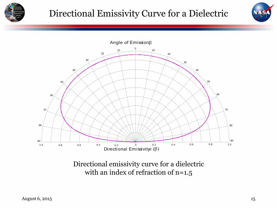
Directional Emissivity Curve for a Dielectric
August 6, 2015 15
Directional emissivity curve for a dielectric with an index of refraction of n=1.5
0 0.2 0.4 0.6 0.8 1.00.20.40.60.81.0
010
20
30
40
50
60
70
80
90
10
20
30
40
50
60
70
80
90
Directional Emissivity
Angle of Emission

Ratio of Hemispherical to Normal Emissivity for Insulators
August 6, 2015 16
Ratio of Hemispherical to Normal Emittance
for an Insulator
0.9
0.91
0.92
0.93
0.94
0.95
0.96
0.97
0.98
0.99
1
1.01
1.02
1.03
1.04
1.05
1.06
1.07
1.08
1.09
1.1
0.4 0.45 0.5 0.55 0.6 0.65 0.7 0.75 0.8 0.85 0.9 0.95 1
Normal Emissivity (n)
h/
n

DB 100 Optical Diagram
August 6, 2015 17
Illumination: Hemispherical Detector: Directional ~7-10 deg Detector type: CsI vacuum thermocouple Detector Range: 5?-40μm? Accuracy: ±0.02 sample must be gray Measurement: Hemispherical-Directional Reflectance
~7-10°
Vacuum CsI Thermocouple
folding
folding mirror
sample tobe measured
focusing mirror
unheated
cavity
heatedcavity
mirror
cavity
Base Plate
Selective
Filter
~ 43C
rotation
Black Anodize
interior

SOC 100 Optics
August 6, 2015 18
Illumination: Hemispherical Detector: 10˚ -80˚ Detector type: FTIR: Si, KBr, Pe Detector Range: 2-100μm
Accuracy: ± ? Measurement: Hemispherical-Directional Spectral

Temp200A Optical Diagram
August 6, 2015 19
Temp 2000A Optical System
Mirror
Detector
Ell ipsodial
Collector
Chopper
InfraredSource
Ele
ctro
nics
Sample
15
Pyroelectric
Illumination: 15˚ Detector: Hemispherical Detector type: Pyroelectric Detector Range: 3-35μm Accuracy: ±0.01 for gray samples ±0.03 for non-gray samples Measurement: Directional-Hemispherical Reflectance

Liquid Helium
LN2 Shroud
Quartz Window
Infrasil Windows
Vacuum Chamber
LHe Shroud
Sample
Manganin W ires
Q
Q
Heat Flow
Gas
M o lec u le
Liquid Helium
LHe Shroud
Sample
Manganin W ires
Aluminum Door
P = 760 torr
P = 1*10 torr-7
P = 2*10 torr-8
Aluminum Door
Base Plate HV Valve
Turbo Pump
AluminumPlate
ra d ia t ed
con
duc
ted
Q
&
Front View
Top View
AluminumDoor
Sample
Dewar Dewar
Silicon Diode
Manganin
Wires
Dewar Supports
A1100 Aluminum
Epoxy
gas
sd
lead lossHeatRadiated
LeH Shroud
LeH Shroud
Emittance by the Calorimetric Technique
August 6, 2015 20

Dielectrics over Metals
* Charts reproduced from Heaney, Triolo, and Hass, “Evaporated Thin Films For Spacecraft Temperature Control Applications”, July 1977.
** Oxide Thickness is represented as /4 at 550 nm.
August 6, 2015 21
Emittance of SiOx Coated Aluminum
as a Function of Oxide Thickness*
0
0.1
0.2
0.3
0.4
0.5
0.6
0.7
0 4 8 12 16 20 24 28 32 36 40
Oxide Thickness**
Em
issiv
ity
e
e(n)
Emittance of Al2O3 coated Aluminum
as a Function of Oxide Thickness*
0
0.1
0.2
0.3
0.4
0.5
0.6
0.7
0 4 8 12 16 20 24 28 32 36 40
Oxide Thickness**
Em
issiv
ity
e
e(n)
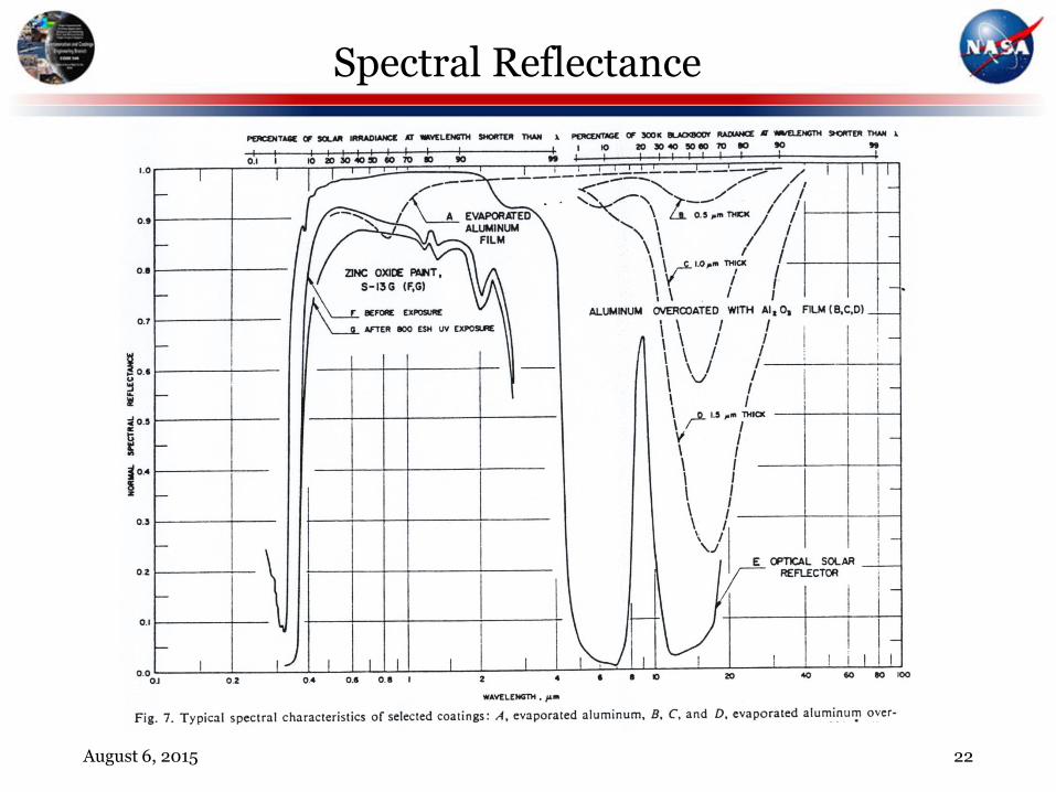
Spectral Reflectance
August 6, 2015 22

Blackbody Spectral Radiance
August 6, 2015 23

Emittance of a Hypothetical Coating and Two Black Body Temperature Curves
August 6, 2015 24
0 2.5 5 7.5 10 12.5 15 17.5 20 22.5 25 27.5 30 32.5 35 37.5 40 42.5 45 47.5 500
0.1
0.2
0.3
0.4
0.5
0.6
0.7
0.8
0.9
1
Emittan ce of Coatin g
Black Bod y 290° K
Black Bod y 90° K
W avelength (microns)
Hem
isph
erc
al E
mit
tanc
e

Calorimetric Results for A276
August 6, 2015 25
Aeroglaze A276 (3.0 mils)
0.0
0.1
0.2
0.3
0.4
0.5
0.6
0.7
0.8
0.9
1.0
0 25 50 75 100 125 150 175 200 225 250 275 300 325 350 375 400
Temperature (°K)
Figure 6.1
He
mis
ph
eri
ca
l E
mit
tan
ce

Infrared Reflectance of A276
August 6, 2015 26
0
0.1
0.2
0.3
0.4
0.5
0.6
0.7
0.8
0.9
1
0 20 40 60 80 100 120
Re
fle
cta
nc
e
Wavelength (microns)

Factors that Influence Thermal Radiative Properties
• Solar Absorptance and/or Emittance Values Influencing Factors: • Surface Finishes
• Highly Polished (mirror-like/optical surface)
• Polished
• Buffed
• Matt
• Machined
• Substrate Texture
• Rough versus Smooth
• Woven
• Bead Blasted (sand, glass, etc…)
• Immersion Rate for Chemical Coatings Processes (i.e., Anodized, Irridited)
• Coating Thickness
• Coating Adherence
• Transmissivity
• Electrical Conductivity
• Contaminants
• Sample/Hardware Size and Configuration
August 6, 2015 27
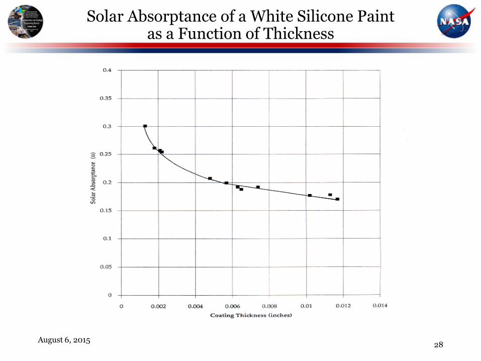
Solar Absorptance of a White Silicone Paint as a Function of Thickness
August 6, 2015
28

NASA-GSFC Thermal Control Coatings Measurement Instrumentation
• AZTek Laboratory Portable Spectroreflectometer (LPSR-300 and LPSR-200)
• Cary 500 IR/Vis/UV Spectroreflectometer
• Geir-Dunkle DB-100 Reflectometer
• SOC-100 Infrared Spectroreflectometer (2μ - 100μ)
• Bi-Directional Reflectance Distribution Function (BRDF)
• Light Analyzer Microscopic Imager
• Calorimetric Emittance Chamber
August 6, 2015 29

Bi-directional Reflectance Distribution Function
• BRDF is a precise measurement of the intensity and direction of the reflection of light from a surface
Power reflected per unit area per solid angle
Power arriving per unit area X cos(s)
• BRDF is a point property of a surface. BRDF is a function of the direction of the incident light and the direction of the scattered light
• Our facility has the capability to measure light scattering at 632.8 nm, 442 nm, and 830 nm
August 6, 2015 30
i
s
s
i
= 0

Bi-directional Reflectance Distribution Function
• Perfectly diffuse or lambertian surface has constant BRDF;
Power reflected per unit area per solid angle =
BRDF X power arriving per unit area X cos(s)
• BRDF measurements/data are used to:
• Calculate the amount of light or energy scattered by specific surfaces in critical applications
• Example -- sunshield
• Evaluate or monitor the condition of a surface with respect to contamination or roughness
• Example -- optics (mirrors)
• Determines specularity of surfaces for special cases
• Calculate solar pressure
August 6, 2015 31

Types of Thermal Control Coatings
• Paints (Z93P, Z306, AZ93, Z93-C55, AZWLA2, Z276, Z307, etc….)
• Metals (Al, Ag, Au, Ni, Stainless Steel, Cu, Mg, Ti, etc…)
• Sheet Films (Kapton®, Ge/Black Kapton®, Black Kapton®, Teflon (FEP), etc…)
• Tapes (Ag/FEP, Al/FEP, Al/Kapton®, Al Foil, Kapton®, Black Kapton® etc…)
• Vacuum Deposited Coatings [Evaporated/Sputtered]
• Metals (Al, Ag, Au, Ti, Ge, Cr, Ni, etc…)
• Dielectrics (Al2O3, SiOx, CCAg, CCAl, Dark Mirror, etc…)
• Conductive Coatings (ITO, ATO, Ge, Z93-C55, Z307, etc…)
• Anodized Aluminum (Black, Hard, Clear, Plain, etc…)
• Chemical Conversion (Irridite, Alodine, etc…)
• Optical Surface Reflectors [OSR]
• Solar Cells
August 6, 2015 32

References
• “Thermal Radiative Properties Coatings”, Y.S. Touloukian, D. P. DeWitt, R. S. Hernicz; Thermophysical Properties of Matter, Volume 9; Pages 1a – 50a, IFI/Plenum, New York-Washington, 1972, (Introduction to Volumes 7, 8 and 9).
• “Spacecraft Thermal Control Coatings References”, NASA/TP-2005-212792, by Lonny Kauder, December 2005.
August 6, 2015 33