tft graphic display module datasheet - … · second data lane in 2 data lane serial interface. ......
TRANSCRIPT

Crystalfontz
TFT GRAPHIC DISPLAY MODULE DATASHEET
Datasheet Release Date 2017-10-04 for
CFAF240320V SERIES • CFAF240320V -020T • CFAF240320V -020T-TS
Crystalfontz America, Inc. 12412 East Saltese Avenue
Spokane Valley, WA 99216-0357 Phone: 888-206-9720
Fax: 509-892-1203 Email: [email protected]
URL: www.crystalfontz.com

Crystalfontz CFAF240320V Series TFT Display Module www.crystalfontz.com Datasheet Release Date 2017-10-04
Page | 2
CONTENTS 1. General Information ............................................................................................................................ 3 2. Module Description ............................................................................................................................. 4 3. Module Variants .................................................................................................................................. 4 4. Features .............................................................................................................................................. 4 5. Mechanical Data ................................................................................................................................. 4 6. Mechanical Drawings .......................................................................................................................... 5 7. System Block Diagram ........................................................................................................................ 7 8. Interface Pin Function ......................................................................................................................... 8 9. 4-Wire Resistive Touch Screen .......................................................................................................... 9 10. AC Characteristics .......................................................................................................................... 10 11. Absolute Maximum Ratings ............................................................................................................ 16 12. DC Characteristics .......................................................................................................................... 16 13. Optical Characteristics .................................................................................................................... 16 14. Backlight Characteristics ................................................................................................................. 17 15. LCD Module Precautions ................................................................................................................ 18

Crystalfontz CFAF240320V Series TFT Display Module www.crystalfontz.com Datasheet Release Date 2017-10-04
Page | 3
1. General Information Datasheet Revision History
Datasheet Release: 2017-10-04 Datasheet for the CFAF240320V Series graphic display modules.
Product Change Notifications
You can check for or subscribe to Part Change Notices for this display module on our website.
Variations Slight variations between lots are normal (e.g., contrast, color, or intensity).
Volatility This display module has volatile memory.
Disclaimer Certain applications using Crystalfontz America, Inc. products may involve potential risks of death, personal injury, or severe property or environmental damage (“Critical Applications”). CRYSTALFONTZ AMERICA, INC. PRODUCTS ARE NOT DESIGNED, INTENDED, AUTHORIZED, OR WARRANTED TO BE SUITABLE FOR USE IN LIFE-SUPPORT APPLICATIONS, DEVICES OR SYSTEMS OR OTHER CRITICAL APPLICATIONS. Inclusion of Crystalfontz America, Inc. products in such applications is understood to be fully at the risk of the customer. In order to minimize risks associated with customer applications, adequate design and operating safeguards should be provided by the customer to minimize inherent or procedural hazard. Please contact us if you have any questions concerning potential risk applications. Crystalfontz America, Inc. assumes no liability for applications assistance, customer product design, software performance, or infringements of patents or services described herein. Nor does Crystalfontz America, Inc. warrant or represent that any license, either express or implied, is granted under any patent right, copyright, or other intellectual property right of Crystalfontz America, Inc. covering or relating to any combination, machine, or process in which our products or services might be or are used. All specifications in datasheets on our website are, to the best of our knowledge, accurate but not guaranteed. Corrections to specifications are made as any inaccuracies are discovered. Company and product names mentioned in this publication are trademarks or registered trademarks of their respective owners. Copyright © 2017 by Crystalfontz America, Inc.,12412 East Saltese Avenue, Spokane Valley, WA 99216 U.S.A.

Crystalfontz CFAF240320V Series TFT Display Module www.crystalfontz.com Datasheet Release Date 2017-10-04
Page | 4
2. Module Description The CFAF240320V series is a full color active matrix TFT (Thin Film Transistor) LCD (Liquid Crystal Display) that uses an amorphous silicon TFT as a switching device. These displays are composed of a transmissive TFT-LCD panel, driver circuit, and an LED backlight. The resolution of these 2.0-inch diagonal active area displays is 240x320 pixels. They can display up to 65/262K colors. This display module has a built-in Sitronix ST7789V Controller.
Please see Sitronix ST7789V LCD Controller Datasheet for further reference.
3. Module Variants • CFAF240320V-020T (TN TFT without touch screen) • CFAF240320V-020T-TS (TN TFT with touchscreen)
4. Features • 240*320 Dot Matrix • +3.3V Power Supply • Viewing Direction: 12 o’clock • Built-in Controller: Sitronix ST7789V (or equivalent) • Operating Temperature: -20°C to +70°C • Storage Temperature: -30°C to +80°C • Interface: 8/9/16/18-Bit MCU / 3/4SPI+16/18-Bit RGB / 3-line/4-line Serial
5. Mechanical Data
Item Specification (mm)
Specification (inch, reference)
Overall Module Dimension 35.80 (W) x 52.10 (H) x 2.65 (D) 1.311 (W) x 1.504 (H) x 0.110 (D)
Active Area 30.24 (W) x 40.32 (H) 1.004 (W) x 1.043 (H)
Pixel Pitch 0.126 (W) x 0.126 (H) 0.008 (W) x 0.008 (H)
Pixel Arrangement RGB Vertical Stripe -
Display Mode Transmissive -
Display Colors 65K/262K -

Crystalfontz CFAF240320V Series TFT Display Module www.crystalfontz.com Datasheet Release Date 2017-10-04
Page | 5
6. Mechanical Drawings

Crystalfontz CFAF240320V Series TFT Display Module www.crystalfontz.com Datasheet Release Date 2017-10-04
Page | 6

Crystalfontz CFAF240320V Series TFT Display Module www.crystalfontz.com Datasheet Release Date 2017-10-04
Page | 7
7. System Block Diagram

Crystalfontz CFAF240320V Series TFT Display Module www.crystalfontz.com Datasheet Release Date 2017-10-04
Page | 8
8. Interface Pin Function Pin No. Symbol Level Function
1 GND P Ground 2 VCI P Supply Voltage (3.3v) 3 IOVCC P Supply Voltage (1.65-3.3v) 4 IM2 I MPU Parallel Interface Bus and Serial Interface Select.
If using RGB Interface you must select serial interface. Fix this pin at VCI and GND.
5 IM1 I 6 IM0 I
7 RESET I This signal will reset the device. Must be applied to properly initialize the chip.
8 CS I Chip Select Input Pin (“Low” enable). Fix this pin at VCI or GND when not in use.
9 DC (SPI-SCL) I
Display Data/Command Selection Pin in Parallel Interface. This pin is used for Serial Interface Clock. DC=’1’: Display Data or Parameter. DC=’0’: Command Data. If not used, fix this pin at VDDI or DGND.
10 WR (SPI-RS) I
Write Enable in MCU Parallel Interface. Display Data/Command Selection Pin in 4-line Serial Interface. Second Data Lane in 2 Data Lane Serial Interface. If not used, fix this pin at VDDI or DGND.
11 RD I Serves as a Read Signal and MCU Read Data at the Rising Edge. If not used, fix this pin at VCI or GND.
12 VSYNC I Frame Synchronizing Signal for RGB Interface Operation. If not used, fix this pin at VCI or GND.
13 HSYNC I Line synchronizing signal for RGB interface operation. If not used, fix this pin at VCI or GND.
14 ENABLE I Data Enable Signal for RGB Interface Operation. If not used, fix this pin at VCI or GND.
15 DOTCLK I Dot Clock Signal for RGB Interface Operation. If not used, fix this pin at VCI or GND.
16 SDA I The Data is Latched on the Rising Edge of the SCL Signal. If not used, fix this pin to GND.
17-34 DB0-DB7 I/O 18-Bit Parallel Bi-directional Data Bus for MCU System and RGB Interface Mode.
35 SDO O SPI Interface Output Pin The Data is Output on the Falling Edge of the SCL Signal.
36 LEDA P Anode Pin of Backlight 37 LEDK1 P Cathode Pin of Backlight 38 LEDK2 P Cathode Pin of Backlight 39 LEDK3 P Cathode Pin of Backlight 40 LEDK4 P Cathode Pin of Backlight 41 XL A/D Touch Panel, Left Glass Terminal (No Touchscreen = No Connection)
42 YU A/D Touch Panel, Top Film Glass Terminal (No Touchscreen = No Connection)
43 XR A/D Touch Panel, Right Glass Terminal (No Touchscreen = No Connection)
44 YD A/D Touch Panel, Bottom Film Glass Terminal (No Touchscreen = No Connection)
45 GND P Ground

Crystalfontz CFAF240320V Series TFT Display Module www.crystalfontz.com Datasheet Release Date 2017-10-04
Page | 9
9. 4-Wire Resistive Touch Screen The touch screen must be driven in one direction, then read in the other direction.
• Typically, the kind of micro-controller that supports the RGB / DPI interface (ARM9, etc.), will also have ADC pins that can be used directly to read the touch screen.
• TI (Texas Instruments) makes I2C / SPI and low-level touch screen controllers. (Typical: www.ti.com/product/tsc2046e).
BASIC CONCEPT FOR READING 4-WIRE RESISTIVE TOUCH SCREENS Create a voltage gradient across the X set of electrodes by setting both X pins to digital output, then driving one low and the other high. Set both Y pins to inputs, with one pin configured as an analog input. Use the Y analog pin to read the voltage. This reading will correspond to the X coordinate of the touch. To read the other channel, reverse the process with the Y pins configured as digital and one X pin as analog. Other factors may need to be addressed such as references, calibration, calibration drift, non-contact, taps, and double taps.
TOUCH SCREEN FEATURES
Item Condition Note Temperature range upon operation Humidity: 20%-90% non-dew,
condensation -20°C ~ 70°C In a simple substance
Temperature range upon storage Humidity: 20%-90% non-dew, condensation -30°C ~ 80°C In a simple substance
Item Value Note Maximum Voltage DC5v -
Resistance Between Terminals X direction [Film Side]: 200-600Ω - Y direction [Glass Side]: 300-900Ω
Insulation Resistance DC 25v 20 MΩ or above
Connect X+~Y and Y+~Y, apply 25v DC between X and Y for performance measurements.
Chattering 10 ms or below - Rating Voltage is DC 5v -
Item Performance Note Input Method Using a Stylus or Finger -
Load Upon Operation
Stylus 60-100g or below
Operation and measurement with a stylus must have the following tip conditions: Stylus material: POM(polyacetal). Tip: Diameter 3.0 mm, SR 0.8 mm
Finger 60-100g or below
Operation and measurement with a simulated finger must have the following tip conditions: Material: Silicon rubber (Hardness: 30°Hs) Tip: Diameter 12.0 mm, SR 12.5mm
Surface Hardness Pencil Hardness: 3H or above Complies with test method JIS K5400.
Item Performance Note Total Light Transmittance 80% or above JIS K7105 Haze 5% or below JIS K7136 Film Specification Polished type wit hared coated surface -

Crystalfontz CFAF240320V Series TFT Display Module www.crystalfontz.com Datasheet Release Date 2017-10-04
Page | 10
10. AC Characteristics

Crystalfontz CFAF240320V Series TFT Display Module www.crystalfontz.com Datasheet Release Date 2017-10-04
Page | 11

Crystalfontz CFAF240320V Series TFT Display Module www.crystalfontz.com Datasheet Release Date 2017-10-04
Page | 12
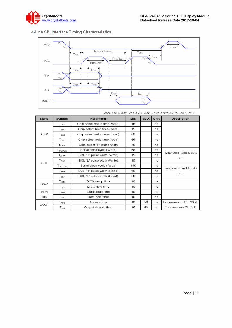
Crystalfontz CFAF240320V Series TFT Display Module www.crystalfontz.com Datasheet Release Date 2017-10-04
Page | 13

Crystalfontz CFAF240320V Series TFT Display Module www.crystalfontz.com Datasheet Release Date 2017-10-04
Page | 14

Crystalfontz CFAF240320V Series TFT Display Module www.crystalfontz.com Datasheet Release Date 2017-10-04
Page | 15
Crystalfontz CFAF240320V Series TFT Display Module www.crystalfontz.com Datasheet Release Date 2017-10-04
Page | 16
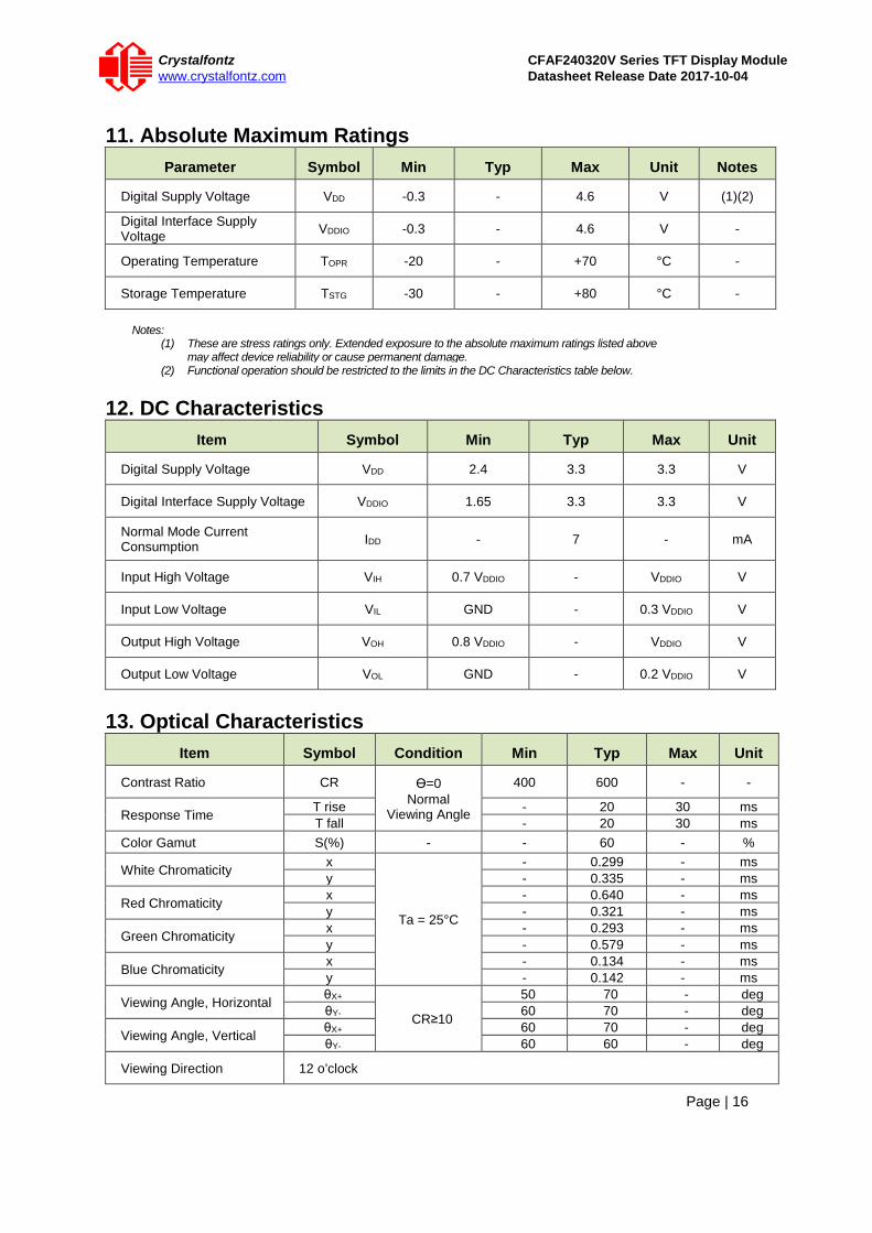
11. Absolute Maximum Ratings
Parameter Symbol Min Typ Max Unit Notes
Digital Supply Voltage VDD -0.3 - 4.6 V (1)(2)
Digital Interface Supply Voltage VDDIO -0.3 - 4.6 V -
Operating Temperature TOPR -20 - +70 °C -
Storage Temperature TSTG -30 - +80 °C -
Notes:
(1) These are stress ratings only. Extended exposure to the absolute maximum ratings listed above may affect device reliability or cause permanent damage.
(2) Functional operation should be restricted to the limits in the DC Characteristics table below. 12. DC Characteristics
Item Symbol Min Typ Max Unit
Digital Supply Voltage VDD 2.4 3.3 3.3 V
Digital Interface Supply Voltage VDDIO 1.65 3.3 3.3 V
Normal Mode Current Consumption IDD - 7 - mA
Input High Voltage VIH 0.7 VDDIO - VDDIO V
Input Low Voltage VIL GND - 0.3 VDDIO V
Output High Voltage VOH 0.8 VDDIO - VDDIO V
Output Low Voltage VOL GND - 0.2 VDDIO V
13. Optical Characteristics
Item Symbol Condition Min Typ Max Unit
Contrast Ratio CR Ɵ=0 Normal
Viewing Angle
400 600 - -
Response Time T rise - 20 30 ms T fall - 20 30 ms
Color Gamut S(%) - - 60 - %
White Chromaticity x
Ta = 25°C
- 0.299 - ms y - 0.335 - ms
Red Chromaticity x - 0.640 - ms y - 0.321 - ms
Green Chromaticity x - 0.293 - ms y - 0.579 - ms
Blue Chromaticity x - 0.134 - ms y - 0.142 - ms
Viewing Angle, Horizontal θX+
CR≥10
50 70 - deg θY- 60 70 - deg
Viewing Angle, Vertical θX+ 60 70 - deg θY- 60 60 - deg
Viewing Direction 12 o’clock

Crystalfontz CFAF240320V Series TFT Display Module www.crystalfontz.com Datasheet Release Date 2017-10-04
Page | 17
14. Backlight Characteristics Item Symbol Min Typ Max Unit
Forward Current IF - 60 80 mA
Forward Voltage VF - 3.2 - V
LCM Luminous LV 450 - - cd/m2
LED Lifetime Hr. 50K - - Hrs.
Uniformity AVG 80 - - %
Notes:
(1) Forward current minimum value is only for reference since the LED brightness efficiency keeps enhancing. Current consumption becomes less and less to achieve the same luminance.
(2) Lifetime is defined as the amount of time when the luminance has decayed to <50% of the initial value (50K hours is an estimate for reference only).

Crystalfontz CFAF240320V Series TFT Display Module www.crystalfontz.com Datasheet Release Date 2017-10-04
Page | 18
15. LCD Module Precautions The precautions below should be followed when using LCD modules to help ensure personal safety, module performance, and compliance of environmental regulations.
15.1. Modules • Avoid applying excessive shocks to module or making any alterations or modifications to it. • Do not make extra holes on the printed circuit board, modify its shape or change the components
of LCD display module. • Do not disassemble the LCD display module. • Do not operate the LCD display module above the absolute maximum rating. • Do not drop, bend or twist the LCD display module. • Soldering: only to the I/O terminals. • Store in an anti-static electricity container and clean environment. • It is common to use the "screen saver" to extend the lifetime of the LCD display module.
o Do not use the fixed information for long periods of time in real application. o Do not use fixed information in LCD panel for long periods of time to extend "screen
burn" effect time. • Crystalfontz has the right to change the passive components, including R3, R6 & backlight adjust
resistors. (Resistors, capacitors and other passive components will have different appearance and color caused by the different supplier.)
• Crystalfontz have the right to change the PCB Rev. (In order to satisfy the supplying stability, management optimization and the best product performance, etc., under the premise of not affecting the electrical characteristics and external dimensions, Crystalfontz has the right to modify the version.).
15.2. Handling Precautions • Since the display panel is made of glass, do not apply mechanical impacts such as dropping from
a high position. • If the display panel is accidently broken, and the internal organic substance leaks out, be careful
not to inhale or touch the organic substance. • If pressure is applied to the display surface or its neighborhood of the LCD display module, the
cell structure may be damaged, so be careful not to apply pressure to these sections. • The polarizer covering the surface of the LCD display module is soft and can be easily scratched.
Please be careful when handling the LCD display module. • Clean the surface of the polarizer covering the LCD display module if it becomes soiled using
following adhesion tape. o Scotch Mending Tape No. 810 or an equivalent o Never breathe the soiled surface or wipe the surface using a cloth containing
solvent such as ethyl alcohol, since the surface of the polarizer will become cloudy. o The following liquids/solvents may spoil the polarizer:
- Water - Ketone - Aromatic Solvents
• Hold the LCD display module very carefully when placing the LCD display module into the system housing.
• Do not apply excessive stress or pressure to the LCD display module. And, do not over bend the film with electrode pattern layouts. These stresses will influence the display performance. Also, be sure to secure the sufficient rigidity for the outer cases.
Crystalfontz CFAF240320V Series TFT Display Module www.crystalfontz.com Datasheet Release Date 2017-10-04
Page | 19
• Do not apply stress to the LSI chips and the surrounding molded sections. • Do not disassemble or modify the LCD display module. • Do not apply input signals while the logic power is off. • Pay sufficient attention to the working environments when handing the LCD display module to
prevent occurrence of element breakage accidents by static electricity. o Be sure to make human body grounding when handling LCD display modules. o Be sure to ground tools to use for assembly such as soldering irons. o To suppress generation of static electricity, avoid carrying out assembly work under
dry environments. o Protective film is being applied to the surface of the display panel of the LCD
display module. Be careful since static electricity may be generated when exfoliating the protective film.
• Protection film is being applied to the surface of the display panel and removes the protection film before assembling it. At this time, if the LCD display module has been stored for a long period of time, residue adhesive material of the protection film may remain on the surface of the display panel after the film has been removed. In such a case, remove the residue material by the method discussed above.
• If electric current is applied when the LCD display module is being dewed or when it is placed under high humidity environments, the electrodes may become corroded. If this happens proceed with caution when handling the LCD display module.
15.3. Storage Precautions • When storing the LCD display modules put them in static electricity preventive bags to avoid
exposure to direct sunlight and fluorescent lamps. Also avoid high temperature and high humidity environments and low temperatures (less than 0°C) environments. (We recommend you store these modules in the packaged state when they were shipped from Crystalfontz). Be careful not to let water drops adhere to the packages or bags, and do not let dew gather on them.
• If electric current is applied when water drops are adhering to the surface of the LCD display module the LCD display module may have become dewed. If a dewed LCD display module is placed under high humidity environments it may cause the electrodes to become corroded. If this happens proceed with caution when handling the LCD display module.
15.4. Designing Precautions • The absolute maximum ratings are the ratings that cannot be exceeded for LCD display module. If
these values are exceeded, panel damage may happen. • To prevent occurrence of malfunctioning by noise pay attention to satisfy the VIL and VIH
specifications and, at the same time, to make the signal line cable as short as possible. • We recommend that you install excess current preventive unit (fuses, etc.) to the power circuit
(VDD). (Recommend value: 0.5A) • Pay sufficient attention to avoid occurrence of mutual noise interference with the neighboring
devices. • As for EMI, take necessary measures on the equipment side. • When fastening the LCD display module, fasten the external plastic housing section. • If the power supply to the LCD display module is forcibly shut down, by such errors as taking out
the main battery while the LCD display panel is in operation, we cannot guarantee the quality of this LCD display module.
o Connection (contact) to any other potential than the above may lead to rupture of the IC.
15.5. Disposing Precautions • Request the qualified companies to handle the industrial wastes when disposing of the LCD
display modules. Or, when burning them, be sure to observe the environmental and hygienic laws and regulations.
15.6. Other Precautions • When an LCD display module is operated for a long period of time with a fixed pattern, the
fixed pattern may remain as an after image or a slight contrast deviation may occur. o If the operation is interrupted and left unused for a while, normal state can be
restored.

Crystalfontz CFAF240320V Series TFT Display Module www.crystalfontz.com Datasheet Release Date 2017-10-04
Page | 20
o This will not cause a problem in the reliability of the module. • To protect the LCD display module from performance drops by static electricity rapture, etc.,
do not touch the following sections whenever possible while handling the LCD display modules.
o Pins and electrodes o Pattern layouts such as the TCP & FPC
• With this LCD display module, the LCD driver is being exposed. Generally speaking, semiconductor elements change their characteristics when light is radiated according to the principle of the solar battery. Consequently, if this LCD driver is exposed to light, malfunctioning may occur.
o Design the product and installation method so that the LCD driver may be shielded from light in actual usage.
o Design the product and installation method so that the LCD driver may be shielded from light during the inspection processes.
• Although this LCD display module stores the operation state data by the commands and the indication data, when excessive external noise, etc. enters into the module, the internal status may be changed. Therefore, it is necessary to take appropriate measures to suppress noise generation or to protect from influences of noise on the system design.
• We recommend that you construct its software to make periodical refreshment of the operation statuses (re-setting of the commands and re-transference of the display data), to cope with catastrophic noise.
• Resistors, capacitors, and other passive components will have different appearance and color caused by the different supplier.
• Crystalfontz has the right to upgrade and modify the product function. • The limitation of FPC bending: