tftp loading of programs into a microcontroller’s flash...
TRANSCRIPT

TFTP loading of programs into a Microcontroller’s flash memory and evaluation of Microchip’s TCP/IP stack with ENC28J60
Kenan Alci 2014-05-28
Project for IK2553 performed at Department of Communication Systems
Examiner and academic adviser Professor Gerald Q. Maguire Jr.
School of Information and Communication Technology (ICT) KTH Royal Institute of Technology
Stockholm, Sweden


i
Abstract This project began with a microprocessor platform developed by two master’s students:
Albert López and Francisco Javier Sánchez. Their platform was designed as a gateway for sensing devices operating in the 868 MHz band. The platform consists of a Texas Instruments MSP430F5437A microcontroller and a Microchip ENC28J60 Ethernet controller connected to the MSP430 processor by a Serial Peripheral Interface.
Javier Lara Peinado implemented prototype white space sensors using the platform developed by the earlier two students. As part of his effort, he partially implemented a Trivial File Transfer Protocol (TFTP) system for loading programs into the flash memory of the microcontroller using Microchip’s TCP/IP stack. However, he was not successful in loading programs into the flash as the TFTP transfer got stuck at the first block.
The first purpose of this project was to find and fix the error(s) in the TFTP loading of programs into the MSP430’s flash memory. The second purpose of this project was to evaluate Microchip’s TCP/IP stack in depth. This report describes measurements of UDP transmission rates. Additionally, the TFTP processing rate is measured and the TFTP program loading code is documented. The report concludes with suggestions for possible improvements of this system.
Keywords: TFTP loading, MSP430 flash, IP stack evaluation

iii
Sammanfattning Projektet startade med en mikroprocessor-plattform som utvecklades av två
masterstudenter: Albert López och Francisco Javier Sánchez. Deras plattform var utformad som en inkörsport för avkänning av apparater som arbetar i 868 MHz-bandet. Plattformen består av en Texas Instruments MSP430F5437A mikrokontroller och en Microchip ENC28J60 Ethernet controller ansluten till MSP430-processor med en SPI-gränssnitt (Serial Peripheral Interface).
Javier Lara Peinado genomförde prototypvitt utrymme sensoreranvända plattformen som utvecklades av de två tidigare nämnda studenter. Som en del av sitt arbete genomförde han delvis ett Trivial File Transfer Protocol (TFTP) system för lastning program i flashminne mikrokontroller med hjälp av Microchips TCP / IP-stack. Men han var inte framgångsrik i lastning program i flash som TFTP-överföringen fastnade vid det första blocket.
Det första syftet för detta projekt var att hitta och åtgärda felet(er) i TFTP laddning av program i MSP430 flashminne. Det andra syftet för detta projekt var att utvärdera Microchips TCP/IP- stack på djupet. I denna rapport beskrivs mätningar av UDP överföringshastighet. Dessutom mäts TFTP bearbetningshastighet och TFTP programladdningskoden dokumenteras. Rapporten avslutas med förslag på möjliga förbättringar av systemet.
Nyckelord:TFTP programladdning, MSP430 flashminne, IP-protokollstackenutvärdering


v
Table of contents Abstract .......................................................................................... i Sammanfattning ............................................................................. iii Table of contents .............................................................................. v List of Figures ................................................................................ vii List of Tables .................................................................................. ix List of acronyms and abbreviations .................................................... xi 1 Introduction .............................................................................. 1
1.1 Problem description ............................................................... 1 1.2 Goals ................................................................................... 1 1.3 Structure of this report ........................................................... 2
2 Background ............................................................................... 3 2.1 What others already have done ............................................... 3
2.1.1 Exploiting wireless sensors ................................................................................... 3 2.1.2 Minding the spectrum gaps .................................................................................. 3 2.1.3 Fixing the PoE functionality .................................................................................. 3 2.1.4 Smart Door Lock ................................................................................................... 4
2.2 Dynamic Host Configuration Protocol ........................................ 4 2.3 Trivial File Transfer Protocol .................................................... 4
2.3.1 Structure of a packet ............................................................................................ 4 2.3.2 Initial connection .................................................................................................. 5 2.3.3 TFTP packets ......................................................................................................... 5
3 Method ..................................................................................... 7 3.1 Objectives ............................................................................ 7 3.2 Hardware ............................................................................. 7
3.2.1 Motherboard ........................................................................................................ 7 3.2.2 HP ProCurve Switch 2626 ..................................................................................... 9 3.2.3 Dell Optiplex GX620 ............................................................................................. 9 3.2.4 MSP430 Programmer ........................................................................................... 9
3.3 Software ............................................................................. 10 3.3.1 Wireshark ........................................................................................................... 10 3.3.2 Code Composer Studio ....................................................................................... 10
3.4 Connecting the embedded platform to the network ................... 11 3.4.1 DHCP server ........................................................................................................ 11 3.4.2 TFTP server ......................................................................................................... 11
4 Analysis ................................................................................... 13 4.1 Network topology ................................................................. 13 4.2 TFTP loading problem ............................................................ 14
4.2.1 Symptom ............................................................................................................ 14 4.2.2 Causes of the problem& fixes ............................................................................ 14 4.2.3 Result .................................................................................................................. 16
4.3 IP stack evaluation ............................................................... 18

vi
4.3.1 UDP Packet sending from MCU to PC ................................................................ 18 4.3.2 UDP Packet sending from ENC28J60 buffer to PC ............................................. 23 4.3.3 Analysis of TFTP processing ................................................................................ 26 4.3.4 Conclusion .......................................................................................................... 28
5 Conclusions and future work ....................................................... 29 5.1 General conclusions .............................................................. 29 5.2 Future work ......................................................................... 30 5.3 Required reflections .............................................................. 30
References .................................................................................... 31 Appendix A .................................................................................... 33
vii
List of Figures Figure 2-1: RRQ/WRQ .......................................................................................................... 5 Figure 2-2: DATA packet ...................................................................................................... 6 Figure 2-3: ACK packet ........................................................................................................ 6 Figure 2-4: ERROR packet .................................................................................................... 6 Figure 3-1: Views of the front and back of the motherboard ................................................ 9 Figure 3-2: TI MSP-FET430UIF ......................................................................................... 10 Figure 4-1: Network topology ............................................................................................. 13 Figure 4-2: Wireshark capture of the failed TFTP process ................................................. 14 Figure 4-3: Memory map of MSP430F5437A .................................................................... 15 Figure 4-4: Memory map of MSP430F5437A after flashing TFTPboot ............................. 16 Figure 4-5: Success in sending TI-TXT file to the motherboard ........................................ 17 Figure 4-6: Memory before loading TI-TXT file ................................................................ 17 Figure 4-7: Memory after loading TI-TXT file ................................................................... 18 Figure 4-8: Flowchart of the Analyze program for sending UDP packets from the
MCU ................................................................................................................. 19 Figure 4-9: Transmission time for sending individual UDP packets of different sizes
from the MCU to the PC's Ethernet controller ................................................. 20 Figure 4-10: Standard deviation of the transmission times shown in the previous figure
(MCU to PC) ..................................................................................................... 22 Figure 4-11: Theoretical vs. measured transmission time to send a UDP packet of the
indicated size .................................................................................................... 23 Figure 4-12: Flowchart of the Analyze program (sending existing UDP packets from
the ENC28J60’s buffer) .................................................................................... 23 Figure 4-13: Transmission time for individual UDP packets of the indicated sizes (i.e.,
transmission time of an existing packet in the ENC28J60’s buffer to PC) ...... 24 Figure 4-14: Standard deviation (ENC28J60 to PC) ............................................................. 25 Figure 4-15: TFTP processing bit rate ................................................................................... 26 Figure 4-16: TFTP boot loading processing time as a function of file size .......................... 28

ix
List of Tables Table 2-1: TFTP opcodes ..................................................................................................... 5 Table 4-1: Estimated transmission time of a single UDP packet based on the
regression analysis ............................................................................................ 21 Table 4-2: SPI processing speed ........................................................................................ 25 Table 4-3: TFTP download and flash programming times for different sized files ........... 27


xi
List of acronyms and abbreviations
CCS Code Composer Studio CPU Central Processing Unit DHCP Dynamic Host Configuration Protocol FET Flash Emulation Tool GUI Graphical User Interface IC Integrated Circuit IDE Integrated Development Environment IP Internet Protocol JTAG Joint Test Action Group LAN Local Area Network MCU Microcontroller Unit NIC Network Interface Controller OS Operating System PC Personal Computer PoE Power over Ethernet PSE Power Sourcing Equipment RAM Random Access Memory RISC Reduces Instruction Set Computer RRQ Read Request SPI Serial Peripheral Interface SRAM Static Random Access Memory TCP Transmission Control Protocol TFTP Trivial File Transfer Protocol TI Texas Instruments TID Transfer Identifier UDP User Datagram Protocol USD United States Dollar WRQ Write Request


1
1 Introduction This chapter specifies the problems that were addressed in this project, the problems
encountered during the project, the goals of the project, and a brief overview of the objectives of the project.
1.1 Problem description This project began with a microprocessor platform developed by Albert López and
Francisco Javier Sánchez as part of their master’s thesis project[1]. Their platform was designed as a gateway for sensing devices operating in the 868 MHz band. The platform consists of a Texas Instruments MSP430F5437A microcontroller unit (MCU) [2] and a Microchip ENC28J60 Ethernet controller[3] connected to the MSP 430 processor by a Serial Peripheral Interface (SPI).
Javier Lara Peinado implemented prototype white space sensors using the platform developed by the earlier two students[4]. As part of his effort he partially implemented a Trivial File Transfer Protocol (TFTP) based bootloader to load programs into the MCU’s flash memory using Microchip’s TCP/IP stack. However, he was not successful in loading programs into the flash memory as the TFTP transfer got stuck at the first block.
The first purpose of this project was to find and fix the error(s) in the TFTP loading of programs into the MSP430’s flash memory. Due to this, a user is unable to easily load new software into the processor. Instead, the user must manual program each board using a Joint Test Action Group (JTAG) programmer. This makes it much harder to develop and deploy applications for this platform.
The second purpose of this project was to evaluate Microchip’s TCP/IP stack in depth. The reason for this examination is that the MCU is connected to the Ethernet controller by an SPI interface. This means analyzing and documenting the system's performance and if possible identifying bottlenecks. For example, does this SPI’s data rate limit the performance of the processor’s maximum sending and receiving data rates. As part of this evaluation measurements of UDP transmission rates were made.
Additionally, the TFTP processing rate was measured and the TFTP program loading code was documented.
1.2 Goals The main goal was to solve the TFTP loading issue in order to improve the usability of the
system, specifically to make it easier to write and deploy new applications, such as the test programs to be used to assess the performance of the platform’s TCP/IP stack. This lead to the following subtasks:
• Solve the TFTP loading problem – so that programs could be loaded from a TFTP server into the MCU’s flash memory,
• Measuring transfer rates with different configurations of the platform, • Identify bottlenecks in the system, and • Suggest improvementsto the system.

2
1.3 Structure of this report This report exists of five chapters. The first chapter introduced the purpose of the project,
stated the project’s goals, and defined a series of subtasks. The second chapter provides the readers background information concerning what has already been done and what the reader needs to know in order to understand this report. The third chapter explains the methods and approaches to be used to solve the problems. The fourth chapter evaluates what was done and gives a comprehensive analysis of the measurement results. Finally, the last chapter summarizes our conclusions, describes what was not achieved, suggests future work that could lead to improvements, and reflects upon several issues related to the project.

3
2 Background This chapter provides the reader with a survey of related work. This is followed by a
description of two protocols (DHCP and TFTP) to allow the reader to better understanding the content of this report.
2.1 What others already have done As stated in the introduction, this project builds upon previous projects. This section
discusses what these previous students did in more detail.
2.1.1 Exploiting wireless sensors
Albert López and Francisco Javier Sánchez developed a gateway to sniff wireless sensor traffic in the 868 MHz band in order to use this data for multiple purposes[1]. The main component of the motherboard is a Texas Instruments’ (TI) MSP430F5437A MCU[2]. This MCU was developed for ultra-low power applications. For network connectivity, they used an Ethernet controller. A Microchip ENC28J60[3] Ethernet controller was chosen due its Serial Peripheral Interface (SPI)[5] enabling it to communicate with the MSP430 MCU. An additional advantage of using this Ethernet controller is that there is no need for an external memory as the Ethernet controller integrates a dual port Random Access Memory (RAM) buffer for receiving and sending data packets. Due to the low power consumption of this platform (motherboard and radio daughterboard), the motherboard was designed so that it could be powered by Power over Ethernet (PoE)[6][7]. In addition to the motherboard, they developed a daughterboard with a radio transceiver for the 760 – 928 MHz band that also connects to the MCU via an SPI interface.
2.1.2 Minding the spectrum gaps
Javier Lara Peinado[4]use the two boards developed by López and Sánchez and added network booting functionality. The goal was to have a boot program stored in the flash memory of the processor that upon power up would use the Dynamic Host Configuration Protocol (DHCP) to:(1) get an IP address, (2) learn the name of a file to be loaded and executed, and (3) learn the IP address of the file server from which this file could be retrieved using the Trivial File Transfer Protocol (TFTP).Furthermore, the complete configuration of the gateway was done by means of DHCP options[8], while the installation of software to be run was to be done by TFTP. Unfortunately, he did not complete the implementation of using TFTP to load the code into the MCU’s flash memory. However, he did implement software that scans the radio spectrum over a programmed range for “gaps”, i.e., white spaces where no devices are transmitting. These measurements of the spectrum occupancy are sent to a server via UDP datagrams.
2.1.3 Fixing the PoE functionality
Julia Alba Tormo Peiró in her master thesis using a number of white space sensors[9]needed to address a problem with the PoE functionality as the PoE power subsystem of the motherboard was not providing enough power to runs the radio scanning process continuously. She successfully fixed this issue and was able to carry out white space sensing with a number of the motherboards together with their daughter board.

4
2.1.4 Smart Door Lock
Rafid Karim and Haidara Al-Fakhri utilized the motherboard and an existing near field communication board (designed as an Arduino shield) to build a prototype of a network powered NFC capable door lock[10].The main idea of their bachelor’s thesis project was to simplify the user’s life. For example, a homeowner could send one-time key to a repairperson or give two weeks access to his/her neighbor while he/she is on vacation so the neighbor can water the plants.
2.2 Dynamic Host Configuration Protocol The Dynamic Host Configuration Protocol (DHCP) is a network protocol that describes
how a computer can dynamically obtain network settings from a DHCP server[8], [11]. The DHCP protocol is based on the Internet Protocol (IP) [12] and works with User Datagram Protocol (UDP) [13] packets. The main feature of DHCP protocol is that it reduces the need for human interaction each time a client joins the network. This protocol is used by the embedded platform to connect to the network.
2.3 Trivial File Transfer Protocol Trivial File Transfer Protocol[14] is a protocol that uses UDP to transfer files. It was first
defined in January 1980 by Karen R. Sollins in IEN 133[15]and revised in July 1992 by Karen R. Sollins in RFC 1350 [16].
The simplicity of this protocol is the main reason for its usage in our project. This protocol was designed to be small and easy to implement. The only functionality of TFTP is to read and write files from/to a remote server. The protocol is similarities to other Internet protocols in passing 8-bit bytes of data.
Every transfer begins with a request to read or write a file. A response from the server indicates an open connection between the client and server. Each data packet that is send has a fixed length blocks of 512 bytes that has to be acknowledged by the receiver. When a packet is sent with less than 512 bytes this means that it is the last data packet. A timeout will occur at the recipient when a packet is lost in the network. It is up to the receiver to ask for a retransmission of the packet by the sender. Because of this stop-and-wait protocol, TFTP provides flow control and eliminates the need of reordering the incoming packets.
Almost all errors cause a termination of the connection. An error is signaled by an error packet, which does not have to been acknowledged or retransmitted. There are three types of events that cause errors: (1) not being able to satisfy the request (e.g., file not found, access violation, or no such user), (2) receiving a packet which cannot be explained by a delay or duplication in the network (e.g., an incorrectly formed packet), and (3) losing access to a necessary resource (e.g., disk full or access denied during a transfer). The only case where an error does not cause a termination of the connection is when the source port of a received packet is incorrect. In this case, an error packet is sent to the originating host.
2.3.1 Structure of a packet
Since TFTP was designed to be implemented on the top of the UDP, the datagram is carried inside an Internet Protocol packet. The resulting packet has an IP header, a UDP header, a TFTP header, and the TFTP data being sent. In addition, a link layer header is added by the interface to allow the packet to be delivered to its destination. TFTP does not specify any values in the IP header; however, TFTP does set some specific values in the UDP header. The UDP header has four fields. The UDP source and destination ports indicate the UDP ports

used byoptionalIdentifie
2.3.2 A T
receive communpacket tfor eachrequest
TIDnumber destinatnumber the servis used a
2.3.3 TFT
Table 2-
Figuopcode field comode. Wown strifield. Thhosts. Bvalue 0
y the senderl checksumers (TIDs) a
Initial
FTP client an ACK f
nication estthat is beinh successivwill be zero
Ds are randois chosen b
tion ports. A69 of the s
ver itself as ias the destin
TFTP p
TP has five t1: TFTP o
ure 2-1 showfield (Op #
ontains “octeWhen netasing format. hemode fiel
Because, theindicates th
r and receivm can be usare used for
connect
initially senfor a WRQtablishes a g acknowle
ve data bloco.
omly choseby two clieA requestinserving hosits source Tnation TID.
packets
types of pacopcodes
Opc
1
2
3
4
5
ws the read#). The opcet”, “netasccii mode isThe filenam
ld makes it ere is no cenhe end of a R
ver. The datsed to detecthe port nu
tion
nds a write rQ or the fir
transfer. Aedged. The ck. The blo
en at each eents is very ng host sent. The respo
TID, while s This pair o
ckets with a
ode Ope
1
2
3
4
5
d request ancode indicatcii”, or “mas used, the hme field is possible to
ntral authoriRRQ or WR
Figure
tagram’s lenct errors, w
umbers in th
request (WRrst data pac
ACK packetblock num
ock number
end of the low. These
nds its initionse of the
source TID of TIDs are
an opcode fo
eration
Read reques
Write reque
Data (DATA
Acknowledg
Error (ERR
nd write reqtes if this i
ail”. In our host translafollowed by
o define othity this musRQ packet.
e 2-1: RRQ
ngth reflectswhich may he UDP data
RQ) or readcket in rests contain t
mbers begin r of a posit
connectione TID’s areial request
e server to tfrom the reqused until t
or each type
st (RRQ)
est (WRQ)
A)
gement (ACK
OR)
quest packeis a RRQ ocase the sen
ates the datay a byte con
her modes ost be done w
Q/WRQ
s the lengthhave been
agram.
d request (Rponse to athe block nwith one aive respons
n so probab used for thto the welhe request quest messahe transfer
e (see Table
K)
et format. Tor WRQ pacnder and rea in the Filentaining a zf cooperatin
with care. A
h of the pacoccurred.
RRQ) and exa RRQ. Thinumber of and are incrse to the fir
bility that the UDP soull-known Uis a TID chage by the rends.
e 2-1).
The first fiecket. The F
ecipient useename fieldzero (0) andng betweenbyte contai
5
cket. The Transfer
xpects to is initial the data
remented rst write
he same urce and
UDP port hosen by requestor
eld is the Filename e netascii d into its d a mode n pairs of ining the

6
DAT(opcodedata is sthat data
Everenable twith thethis ACa transfe
Figu5. The estring an
TA packetse = 3). The send. The da block is th
ry data packthe other pae opcode 4.K indicates
fer a WRQ i
ure 2-4showerror code nd the pack
transfer theblock num
data field cohe last block
ket should barty to send/. Figure 2-3s the block ns acknowle
ws the strucfield indica
ket ends with
e actual datmber begins ontains the k.
Figure 2
be acknowle/request the3 shows thenumber of thdged with b
Figure
ture of an Eates the typh a zero byt
Figure 2
ta. Figure 2with one aactual data
2-2: DATA
edged to ene next blocke structure he DATA pblock numb
2-3: ACK
ERROR pacpe of error. te.
2-4: ERRO
2-2 shows thand incremea and is 512
A packet
nsure the cok. This is doof an ACK
packet beinger of zero.
K packet
cket. The oThe error m
OR packet
he structureents each ti2 bytes long
nsistency oone by send
K packet. Thg acknowled
pcode of anmessage is
e of a DATAime a new g; if not, thi
of the transfeding an ACKhe block nudged. At the
n ERROR pin netascii
A packet block of is means
fer and to K packet umber in e start of
packet is and the

7
3 Method This chapter explains how we will achieve the goals of this project. Additionally, the tools
that used to realize these goals are discussed.
3.1 Objectives Several sub goals were defined for this project based upon the goals of the project (as
described in Section 1.2). These sub goals are divided into two sets:
1. TFTP boot loading:
• Connecting the board to the network in such a way that each board has its own IP address,
• Detect the cause of the TFTP loading problem, and • Finally, applying the best solution to solve this problem.
2. IP stack evaluation:
• Measuring the transfer rate from the MCU to a remote PC (located on the same isolated local area network) and
• Measuring Ethernet controller buffer to PC transfer rate.
3.2 Hardware This section discusses the hardware used in this project.
3.2.1 Motherboard
As stated earlier the motherboard has been used in a number of projects (previously described in Section 2.1). The motherboard uses one SPI interface to connecting a daughterboard. This enables the user to attach a new daughterboard without needing to change any other part of the motherboard. The first daughterboard was a radio module for the 868 MHz band (see Section 2.1.1). The second daughterboard was an Arduino NFS shield(see Section 2.1.4).
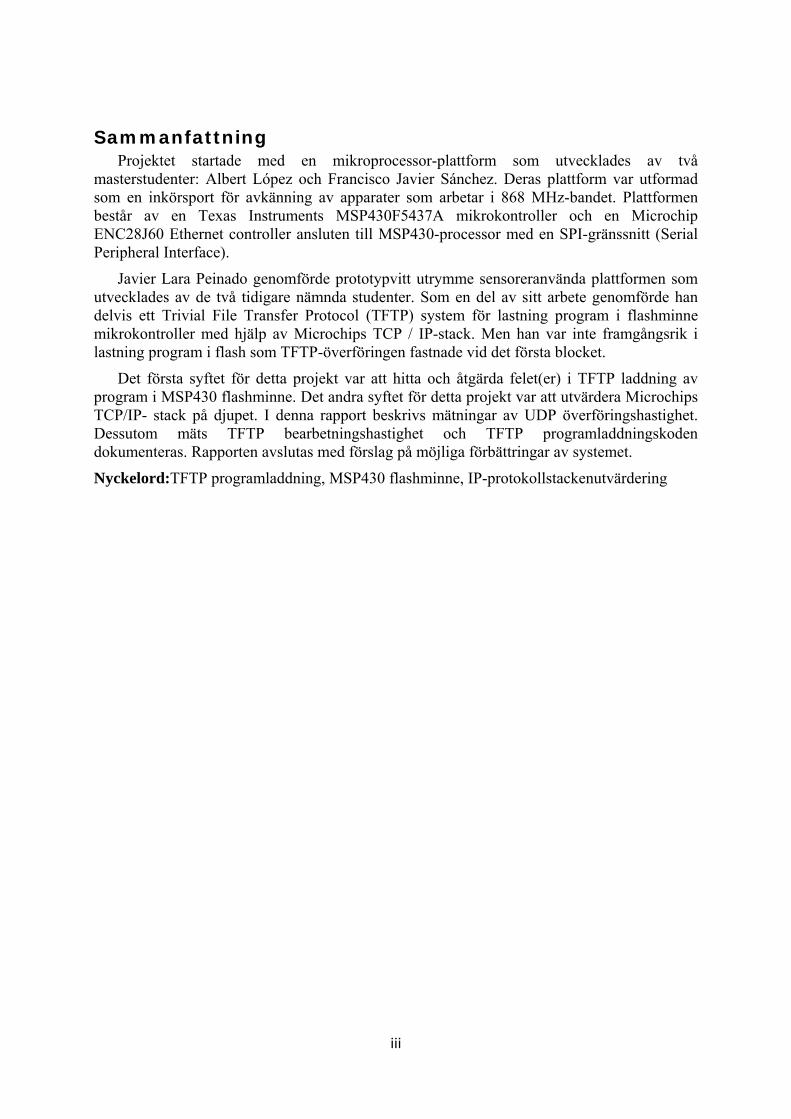
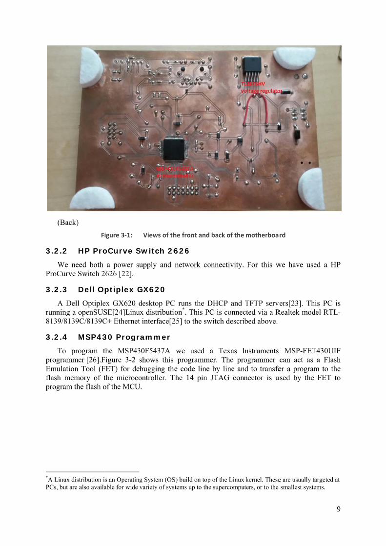
Figure 3-1 shows the front and back of the motherboard. The board consists of two means of powering the supplies powering, processing, networking, and in interface to a daughterboard. This motherboard together with an optional daughter card is an embedded networked computing platform. The motherboard can be powered by an external DC power supply or via PoE. The selection of the power source is up to the user by changing the position of the jumper to choose the desired option. The board can work with any DC supply that provides power between 3.3V and 60V because of the TL2575HV step-down converter[17].PoE is the preferred energy source because the platform will typically be connected to a PoE capable Ethernet switch* to provide both power and network connectivity.
* This switch will act as Power Sourcing Equipment (PSE). Alternative a PoE power injector could be used.

8
The microcoInstructi4 KB ofthat we very carone is, connectEtherneInstrumfeatures
TherLoader only themicroco
Furtwhile thour case
(Fro
main coontroller. Thion Set Cof Static Rancan store r
reful with uas we alrea
t to the Ethet controller
ments TPS23s needed to r
re are two (BSL) inte
e JTAG inteontroller.
thermore, thhe use of thee we have p
ont)
omponent ohis is a 16-
omputer (RIndom Acceselatively larusing the Rady discussehernet contrr is connect375[18]8-pirealize an IE
possible werface or theerface is inc
he motherboe other is pr
programmed
of the bo-bit MCU fISC) mixedss Memory rge amount
RAM of the ed, used to roller. The ted to an Rin integrateEEE 802.3a
ays to proge Joint Tescluded in th
oard is equirogrammabld this button
oard is thfrom TI’s Md signals fa
(SRAM) ats of data anmicrocontr connect thEthernet co
RJ45 socketed circuit (Iaf [19] comp
gram the mst Action Ghe board we
ipped with le, so the den to jump to
he Texas MSP430 ulamily. This nd 256 KB nd instructioroller. This he daughterbontroller is t. To providIC) is usedpliant powe
icrocontrollGroup (JTAGe used the J
two buttonseveloper can
o the program
Instrumentstra-low powversion ofof Flash m
ons in flashmicrocontr
board and ta Microchide PoE fund. This IC ered device.
ler. Either uG) interfaceJTAG interf
s. One button do whatevm loaded us
s MSP430wer MCU Rf the chip h
memory. Thih, but we haroller has twthe other isip ENC28Jnctionality, contains al
.
using the Be.[20][21] Bface to prog
on is a resever he/she wsing TFTP.
0F5437A Reduced has only is means ave to be wo SPIs: s used to 60. This a Texas
ll of the
Bootstrap Because, gram our
et button, wants. In
(Bac
3.2.2 We
ProCurv
3.2.3 A D
running8139/81
3.2.4 To
programEmulatiflash mprogram
*A Linux PCs, but a
ck) Fi
HP Pro
need both ve Switch 2
Dell O
Dell Optipleg a openSUS139C/8139C
MSP43
program tmmer [26].Fion Tool (F
memory of tm the flash o
distribution iare also availa
igure 3-1:
oCurve S
a power su2626 [22].
ptiplex G
ex GX620 dSE[24]LinuC+ Ethernet
30 Progr
the MSP43Figure 3-2 FET) for dethe microcoof the MCU
s an Operatingable for wide
Views of th
Switch 26
upply and
GX620
desktop PCux distributiot interface[2
rammer
30F5437A shows this bugging theontroller. T
U.
g System (OSvariety of syst
he front and
626
network co
C runs the Don*. This P
25] to the sw
we usedprogramm
e code lineThe 14 pin
S) build on toptems up to the
back of the
onnectivity.
DHCP and C is connec
witch descri
a Texas Imer. The pro
by line anJTAG conn
p of the Linuxe supercompu
motherboa
For this w
TFTP servcted via a Rbed above.
Instruments ogrammer
nd to transfenector is u
kernel. Theseters, or to the
rd
we have use
vers[23]. ThRealtek mod
MSP-FETcan act as er a program
used by the
e are usually tsmallest syste
9
ed a HP
his PC is del RTL-
T430UIF a Flash
m to the FET to
targeted at ems.

10
3.3 SIn th
3.3.1 Wire
packets programfunctionthat allosendingdata wetransfer
3.3.2 The
Instrumprovidenegativehas alsothe TFTable to u
*Promiscuonly the findicated
Softwarehis section,
Wiresh
eshark[27]iby setting
m is widelnality is simows the us
g and receivie expected.s between t
Code C
Integrated ments’ Eclip
s everythine part of tho a free versTP Boot prouse the free
uous mode is frames that areit is interested
e we will disc
hark
is a very pg the Netwly used fo
milar to tcpder to easilying packets For examhe embedde
Compose
Developmepse IDE [29ng necessarhis IDE is thsion that is
ogram has a version of
a configuratioe specifically d in.
Figure 3-2
cuss the sof
popular freework Interfaor troubleshdump [28],by sort and , Wireshark
mple, we used platform
er Studio
ent Environ9]based Cory to develhe price. Thlimited in ccode size othis IDE.
on of the NIC for this NIC,
: TI MSP-
ftware tools
e and openace Controlhooting, p
but the progfilter captu
k was used ted Wiresha
m and the PC
o
nment (IDE)ode Compoop a progrhe full verscode size (uof about 14
that causes thbroadcast fram
-FET430UIF
s we used to
n-source paller (NIC) acket anal
gram has a Gured packetto analyze wark to chec
C that serves
) that we usser Studio ram for thesion is quiteup to 16 KBKB this iss
he NIC to recemes, or multic
o achieve ou
acket analyin promiscysis, and
Graphical Us. Since th
whether the ck if there s as a server
sed during t(CCS) ver
e MSP430 e expensiveB) or in timsue not an o
eive all incomicast frames tha
ur goals.
yzer use to cuous modemuch mor
User Interfachis project i
packets conwere DHC
r.
this project rsion 5.4.[3MCU fam
e. Fortunateme (180 daysobstacle, so
ming frames rathat the NIC ha
capture e * . This re. This ce (GUI) involved ntain the
CP/TFTP
is Texas 30] CCS
mily. The ely, CCS s). Since we were
ther than s

11
3.4 Connecting the embedded platform to the network This section explains how the embedded platform is attached to the network and how it
obtains an IP address and then downloads programs.
3.4.1 DHCP server
The platform needs an IP address to join the network, to learn what file it is to download, and to learn the IP address of the TFTP server, hence we need a DHCP server. This DHCP server runs on top of the openSUSE operating system. When the platform is initially connected to the server via the PoE capable switch, it will automatically ask for an IP address from the DHCP server (running on the desktop PC). This IP address is assigned based upon the MAC address that is established by the “TFTPboot” program (written previously by Javier Lara Peinado – see Section 2.1.2). This network boot loader not only implements the DHCP client, but it will make TFTP requests to retrieve the program, and saves the received program in the flash memory.
The DHCP server is installed with YaST[31], an management tool for openSUSE. In addition to installing the DHCP server, we also need to configure it correctly. This means that we need to make an entry in the DHCP server’s configuration file configured for the specific device that we want to connect. This means that we make a host specific entry in the configuration file using the same MAC address that we have programmed into the platform when installing the TFTPboot loader in both block of the flash memory. As noted in Javier Lara Peinado’s thesis we use an address from the Locally Administered Address Range x2-xx-xx-xx-xx-xx, specifically from 02-00-00-xx-xx-xx.
3.4.2 TFTP server
One of the biggest advantages of a TFTP server is that is simplifies providing programs to embedded platforms. This project will take advantage of the TFTP server installed on the desktop PC. The TFTP server was also installed and configured using YaST. However, before we could use this to load our network interface testing programs we first had to overcome the problem of downloading programs via TFTP and storing them in the flash memory. The details of how this problem was solved are given in Section 4.2.


4 AnThis
This invthe sour"https://
4.1 NFigu
connectconnect
Wheserver to“Verifyithesis[3some cothe TFTinitially
nalysis s chapter wvolved progrce code an/github.com
Networkure 4-1 illusted via an Ets the PC (ru
en the motho obtain an ing the ne2].After theonfigurationTP server), ty did not do
will explain gramming thnd addition
m/kekovski/M
k topologstrates the nEthernet cauns a DHCP
herboard is IP address
twork conne DHCP sen (specificathe TFTPbowhat it sup
the methodhe MSP430
nal documenMSP430", w
gy network top
able to the P and a TFT
initially co. Detailed innection” oferver has aslly the namoot programposed to do
Figure 4-1
13
ds used to a0 MCU andnts are pubwhose struc
pology of tHP ProCur
TP server).
onnected to nformation f Rafid Kassigned the
me of the prm[33]starts ro. Details of
: Networ
accomplish d making a blicly availacture is expl
the test envrve Switch
the networkabout this
arim and Hmotherboarogram to berunning. Unf this are giv
rk topology
the goals sseries of m
able via theained in App
vironment. T2626. Ano
k it negotiaprocess is g
Haidara Al-rd an IP ade loaded annfortunatelyven in the n
stated in Chmeasuremene Github reppendix A.
The motherother Ethern
ates with thgiven in Sec-Fakhri's baddress and pnd the IP ady, this boot next subsect
hapter 3. nt. All of epository
rboard is net cable
e DHCP ction 4.1 achelor's provided ddress of program ion.
14
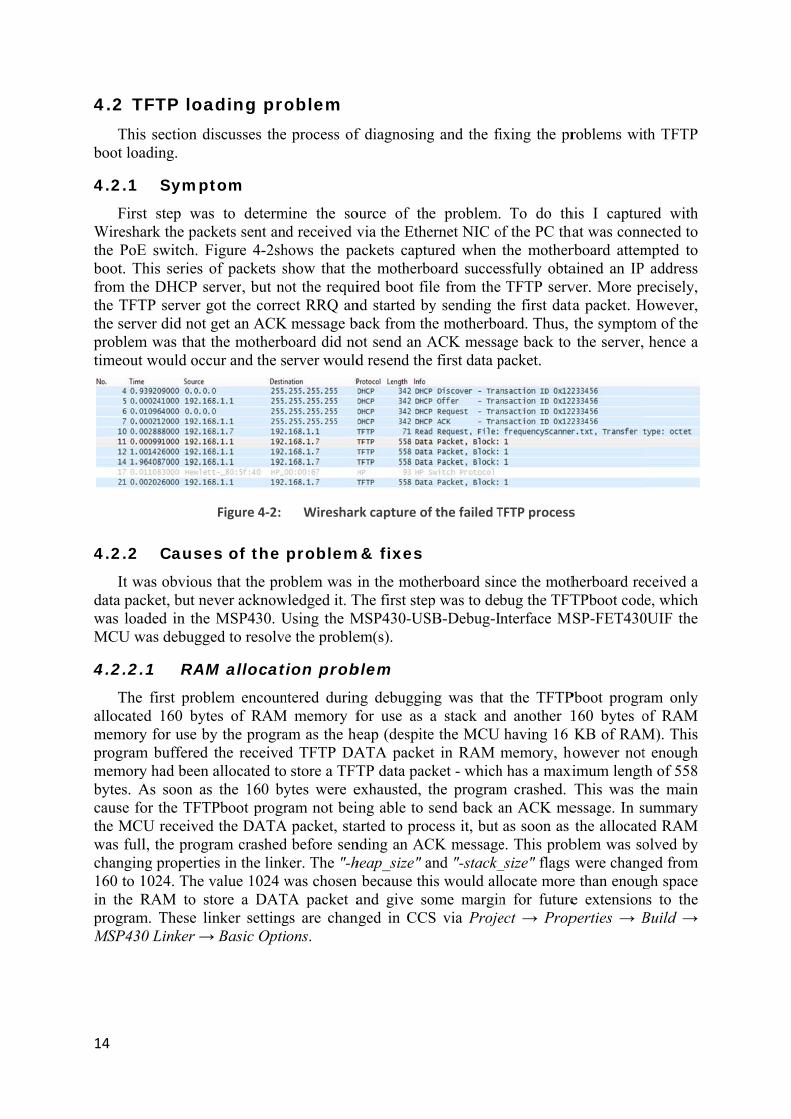
4.2 TThis
boot loa
4.2.1 First
Wireshathe PoEboot. Thfrom thethe TFTthe servproblemtimeout
4.2.2 It w
data pacwas loaMCU w
4.2.2.
The allocatememoryprogrammemorybytes. Acause fothe MCwas fullchangin160 to 1in the RprogramMSP430
TFTP loas section diading.
Sympt
t step wasark the packE switch. Fihis series oe DHCP se
TP server gover did not gm was that t
would occu
Causes
was obvious cket, but nevaded in the was debugge
.1 RAM
first probled 160 bytey for use bym buffered ty had been aAs soon as or the TFTPU received l, the progr
ng propertie1024. The vRAM to sto
m. These lin0 Linker →
ding proscusses the
tom
to determkets sent anigure 4-2sh
of packets server, but noot the correget an ACKthe motherbur and the s
Figure 4-2:
s of the
that the prover acknowMSP430. U
ed to resolve
M allocat
lem encounes of RAMy the prograthe receivedallocated tothe 160 by
Pboot progrthe DATA
am crasheds in the link
value 1024 wore a DATnker setting Basic Opti
oblem process of
mine the sod received v
hows the pashow that thot the requiect RRQ an
K message bboard did noerver would
Wireshar
problem
oblem was iwledged it. TUsing the Me the proble
tion prob
ntered durinM memory f
am as the hed TFTP DA store a TFTytes were eram not bei
A packet, stad before senker. The "-hwas chosen
TA packet ags are chanons.
f diagnosing
ource of thvia the Etheackets captuhe motherbired boot find started byback from thot send an Ad resend the
rk capture of
m& fixes
in the mothThe first stepMSP430-USem(s).
blem
ng debugginfor use as eap (despiteATA packeTP data pacexhausted, ting able to arted to pronding an ACheap_size" a
because thand give so
nged in CCS
g and the fi
e problem.ernet NIC oured when
board succele from they sending t
he motherboACK messae first data p
f the failed T
herboard sinp was to deb
SB-Debug-I
ng was thata stack ande the MCU
et in RAM cket - whichthe programsend back acess it, but
CK messageand "-stack_is would allome marginS via Proje
ixing the pr
To do thof the PC tha
the motherssfully obtaTFTP serv
the first datoard. Thus, age back to packet.
TFTP process
nce the mothbug the TFTnterface M
t the TFTPd another 1having 16 memory, ho
h has a maxim crashed. an ACK meas soon as
e. This prob_size" flags locate moren for futureect → Prop
roblems wit
his I capturat was connrboard attemained an IPver. More pta packet. Hthe symptothe server,
s
herboard reTPboot codSP-FET430
Pboot progr160 bytes oKB of RAM
however notimum lengtThis was t
essage. In sthe allocate
blem was sowere chang
e than enouge extensionperties → B
th TFTP
red with nected to mpted to P address precisely, However, om of the hence a
eceived a de, which 0UIF the
ram only of RAM M). This t enough th of 558 the main summary ed RAM olved by ged from gh space
ns to the Build →

4.2.2.
Unfoagain. Awritten occurs i
The creates the MSPthe flashlinker gin flash a byte tocrashed
The change to the nsystem mis 14 Kshould sdownloato avoidaddress the firstof the flthe amoamount
.2 Ove
fortunately, After hours
to the flasis it necessa
TI-TXT fila TI-TXT fP430F5437Ah memory. F
generates a fmemory an
o the flash .
solution isthe starting
next free avamemory ma
KB is size. Hstart to loadaded prograd conflicts for FLASH
t 14 KB of flash memorount of avaiof flash me
erwrite p
after succeof debuggi
sh memory ary to under
le format isfile when yA the linkerFigure 4-3 sfile to be lond starts at memory it
Figure
s to find theg address of ailable memap in the LiHence withded the newam should bwith the b
H has to be flash memory is on theilable Flashemory givin
roblem
essfully bufing it turnedthe progra
stand the fo
s a ASCII hyou build ar indicates tshows the maded at 5C05C00h. Thutried to ove
e 4-3: Me
e last used f the programmory addresinker Commh simple ma
w program. Abe loaded. T
boot loader.changed froory and stare same line h memory sng 6B80h.Fi
ffering the d out that e
am stopped ormat of a T
hexadecimalproject. Bythat the promemory ma00h. Howevus, each timerwrite itsel
emory map o
address bym to be loadss in the fla
mand File haath is it poAdding 14 KTherefore, . In the Linom 0x5C00rt loading thas the start
shrinks, henigure 4-4 sh
first DATAeach time th
working. TI-TXT file
l file containy default whgram shoul
ap of the MSver, the TFT
me the TFTPlf. The resu
of MSP430F5
y the TFTPbded into flaash memoryad to be cha
ossible to caKB (3800h)9400h was nker Comm
0 to 0x9400he programting address
nce 3800h ishows the me
A packet thhe first byteTo understa[34].
ning a MSPhen a prograd start from
SP430F5437TPboot progPboot progrult of this w
5437A
boot in thesh memory
y. To do thianged. The alculate the) to 5C00h chosen as t
mand File o. This tells tfrom addre
s and must s subtractedemory map
he program es were abotand why th
P430 prograram is generm the first ad7A. In this gram is alsoram wanted
was that the
e flash memy via the boois, the valueTFTPboot
e address windicates wthe starting
on line 63 the programess 9400h. also be cha
d from the pafter these
15
crashed out to be his error
am. CCS rated for ddress in case, the o located d to write
program
mory and otloader- es of the program
where we where the g address the start
m to skip The size anged as previous steps.

16
4.2.2.
Not Several logic. N"WRONthe voidThis lin
4.2.3 Afte
the MSPmessagememory
Figure
.3 Sma
everythingsmall erro
Namely anNG_FORMAd Flash_segne of code is
Result
er all these P430F5437Aes receivedy contents in
e 4-4: Me
all fixes
g was fixedrs in the co
n equal sigAT_ERRORgmentErase s located on
t
steps was iA's flash m
d for each n the MSP4
emory map o
d after solviode were d
gn was for". Subseque(unsigned
line 74 of f
it possible tmemory. Figu
of them. F430's flash m
of MSP430F5
ing the RAdetected. Thrgotten on ently an unnintbaseAdd
flash.c. This
to downloaure 4-5disp
Furthermorememory bef
5437A after
AM allocatihe first one
line 143 necessary redress, unsigs reset caus
d a TI-TXTlays the DA
e, Figure 4fore and afte
flashing TFT
on and ovewas a bad
of Parser.ceset of poin
gned char *Fed also a cr
T file from ATA packet-7 and Figer download
TPboot
erwriting prd loop in thc, which cnter was exeFlash_ptr)
rash of the p
the TFTP sts sent and tgure 4-8 shding the pro
roblems. he parser caused a ecuted in method.
program.
server to the ACK hows the ogram.

Figgure 4-5:
Figure
Success in s
4-6: Mem
sending TI-TX
mory before
XT file to the
e loading TI-T
e motherboa
TXT file
ard
17

18
CCSbootloaduser losapplicatone werpoints talready image o
4.3 IThe
for the evaluatimeasureprogram[36]).
4.3.1 The
PC's Ethstack’s platformmaximu *This pro
S's free versder does noses 14 KB tion includere really prto the subroincluded in
of the progra
P stack major goalMSP430F5
ion and givements a te
m contains
UDP P
first test mhernet port.UDP modu
m a good oum UDP da gram is availa
Figure
sion does noot have this
of flash mes the DHCressed for foutines in tn the boot lam being do
evaluatl of this pro5437A and ve an overest programa code snip
acket se
measures ho This measuule. The resoverview h
ata rate they
able from the
e 4-7: Me
ot allow us s limitation,
memory to tP, UDP, IPflash memothe TFTPboloader couldownloaded)
tion oject was to
running onrview of thm called "Appet from a
ending fr
ow fast the Murement tessults from
how fast thy can expect
Github reposi
emory after
to load mor thus avoidthe TFTPbo
P, and Etherory space ioot applicad be reused).
o evaluate thn this mothhe measureAnalyze" wanother per
rom MCU
MCU can csts the transmthese tests
he MCU cat. The progr
itory.
loading TI-TX
re than 16 Kding this resoot applicarnet controlit would beation so thad (rather tha
he Microchherboard. Tements that
was written rformance t
U to PC
create UDPmit performwill give a
an send UDram sends 1
XT file
KB of codestriction of Cation. Note ler interfaci
e possible tt the netwo
an including
ip TCP/IP sThis sectiont were madfor the MC
testing prog
P packets anmance of theapplication DP packets1024 UDP p
e. However, CCS. Howethat the TFing functionto expose torking relatg it yet aga
stack whenn will descrde. To makCU*. The gram (see [
nd send thee Microchipdevelopers
s, i.e., whapacket with
the new ever, the FTPboot nality. If he entry ted code in in the
n adapted ribe this ke these Analyze [35] and
m to the p TCP/IP for this at is the h a given
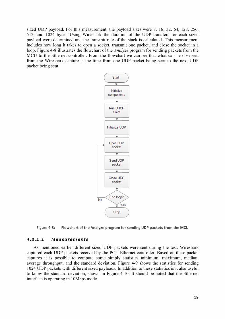
sized U512, anpayloadincludesloop. FiMCU tofrom thpacket b
Fig
4.3.1.
As mcapturedcapturesaverage1024 UDto knowinterfac
UDP payloadnd 1024 byd were deters how longigure 4-8 illo the Ether
he Wiresharbeing sent.
gure 4-8:
.1 Mea
mentioned d each UDPs it is pos
e throughpuDP packets
w the standae is operatin
d. For this ytes. Using rmined and
g it takes tolustrates thernet controllrk capture i
Flowchart o
asuremen
earlier diffP packets resible to co
ut, and the swith differ
ard deviationg in 10Mb
measuremeWireshark
d the transmo open a soce flowchartler. From this the time
of the Analyz
nts
ferent sized eceived byompute somstandard derent sized paon, shown ibps mode.
ent, the paythe durati
mit rate of tcket, transmof the Analhe flowchafrom one U
ze program f
UDP packthe PC’s E
me simply eviation. Figayloads. In in Figure 4
yload sizeson of the U
the stack is mit one paclyze programart we can sUDP packe
for sending U
kets were seEthernet con
statistics mgure 4-9 shaddition to
4-10. It shou
were 8, 16UDP transfcalculated.
cket, and clm for sendinsee that whet being sen
UDP packets
ent during ntroller. Basminimum, mhows the stthese statis
uld be note
6, 32, 64, 1fers for eac. This measlose the socng packets
hat can be ont to the ne
s from the M
the test. Wsed on thesmaximum, tatistics for stics is it alsed that the
19
28, 256, ch sized surement cket in a from the observed ext UDP
MCU
Wireshark e packet median, sending
so useful Ethernet

20
Figure 4-9: Transmission time for sending individual UDP packets of different sizes from the
MCU to the PC's Ethernet controller
Minimum and maximum time: The minimum and maximum transmission times increases as the payload size is increased. However, the difference between the minimum and maximum value is relatively small. This small difference is not surprising as the MCU is only executing the loop of "Analyze" test program shown in Figure 4-8.
Median time: These statistics clearly show an exponential pattern. We did a regression analysis of this data to compute the base time to do the socket opening and closing as well as the time to invoke the packet sending process, then we found the coefficient of the term representing the size of the packet. This coefficient gives us the time per byte of payload.
8 16 32 64 128 256 512 1024Min 0.986 1.042 1.206 1.520 2.197 3.535 6.177 11.471Max 1.008 1.117 1.262 1.614 2.267 3.577 6.213 11.520Median 0.996 1.079 1.234 1.567 2.234 3.555 6.200 11.497Avg 0.996 1.079 1.234 1.567 2.233 3.555 6.200 11.497
0.000
2.000
4.000
6.000
8.000
10.000
12.000
14.000
Tran
smis
sion
tim
e [in
ms]
UDP Payload [Bytes]
Transmission time for sending individual UDP packets of different sizes from the MCU to the
PC's Ethernet controller
Min
Max
Median
Avg

21
Regression analysis (times given in ms) Regression Statistics
Multiple R 0.999999482 R Square 0.999998963 Adjusted R Square 0.99999879 Standard Error 0.004026769
Observations 8
ANOVA df SS MS F
Regression 1 93.83381421 93.83381421 5786899.254 Residual 6 9.72892E-05 1.62149E-05
Total 7 93.8339115
Coefficients Standard Error t Stat P-value Intercept 0.908904725 0.001796636 505.8924481 4.0265E-15
UDP payload 0.010338609 4.29773E-06 2405.597484 3.48309E-19
Now is it possible to compose a formula to compute the time to send a packet with some amount of payload.
Time to send a packet = fixed cost + transmission per byte of payload * x
fixed cost = intercept coefficient
transmission per byte of payload = UDP payload coefficient
x = UDP payload size
Because of the extremely small P-value is it possible to predict almost 100% exactly how much time it will take to transmit a UDP packet containing some amount of payload. The formula above is applied and Table 4-1 and shows the comparison between the estimated and measured results. Note that the fixed cost of sending a zero byte sized payload UDP packet is 0.908904725 ms.This time represents the time required to open and close the socket as well as the time to issue the command to send the packet buffered in the Ethernet controller. Table 4-1: Estimated transmission time of a single UDP packet based on the regression analysis
UDP Payload Estimated transmission time (ms)
Measured transmission time(ms)
8 0.9916136 0.996000
16 1.0743225 1.079000
32 1.2397402 1.234000
64 1.5705757 1.567000
128 2.2322467 2.234000
256 3.5555886 3.555000
512 6.2022725 6.200000
1024 11.4956403 11.497000
22
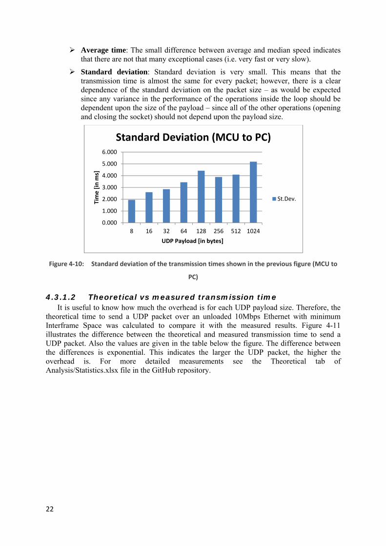
Average time: The small difference between average and median speed indicates that there are not that many exceptional cases (i.e. very fast or very slow).
Standard deviation: Standard deviation is very small. This means that the transmission time is almost the same for every packet; however, there is a clear dependence of the standard deviation on the packet size – as would be expected since any variance in the performance of the operations inside the loop should be dependent upon the size of the payload – since all of the other operations (opening and closing the socket) should not depend upon the payload size.
Figure 4-10: Standard deviation of the transmission times shown in the previous figure (MCU to
PC)
4.3.1.2 Theoretical vs measured transmission time It is useful to know how much the overhead is for each UDP payload size. Therefore, the
theoretical time to send a UDP packet over an unloaded 10Mbps Ethernet with minimum Interframe Space was calculated to compare it with the measured results. Figure 4-11 illustrates the difference between the theoretical and measured transmission time to send a UDP packet. Also the values are given in the table below the figure. The difference between the differences is exponential. This indicates the larger the UDP packet, the higher the overhead is. For more detailed measurements see the Theoretical tab of Analysis/Statistics.xlsx file in the GitHub repository.
0.000
1.000
2.000
3.000
4.000
5.000
6.000
8 16 32 64 128 256 512 1024
Tim
e [in
ms]
UDP Payload [in bytes]
Standard Deviation (MCU to PC)
St.Dev.

Figure
4.3.2 Not
transfer interestiresend tresult win the psending
Fig
ThM
Tim
e [in
ms]
4-11: Theo
UDP P
only is thebytes to/f
ing. In this the packet
was a faster previous meg packets alr
gure 4-12:
heoretical 0Measured 0
0.0002.0004.0006.0008.000
10.00012.00014.000
The
oretical vs. m
acket se
e transmit tifrom the Mmeasuremethat is alretransmissioeasurementready contai
Flowchart o
8 16.701 0.701.996 1.079
eoretica
measured tra
ending fr
ime of packMCU to thent rather thady availab
on time froms. Figure 4ined in the E
of the Analyz
ENC
321 0.893 19 1.234 1
UDP pa
al vs. me
ansmission tsize
rom ENC
kets departinhe ENC28Jhan creatingble in the Em the ENC24-12illustratENC28J60’
ze program (
C28J60’s buf
64 1281.050 1.421.567 2.23
ayload size [in
easured
time to send
28J60 b
ng from MCJ60 Etherng a new UDEthernet con28J60 to thetes the logi’s buffer to
sending exis
ffer)
8 2566 2.2254 3.555
n bytes]
d transm
d a UDP pack
uffer to
CU interestet controlleP packet eantroller's bue PC's Ethec of the Anthe PC’s Et
sting UDP pa
512 1023.852 7.126.200 11.4
mission t
ket of the ind
PC
ting, but theer’s buffer ach time, wuffer. The eernet contronalyze progthernet cont
ackets from
2423
497
time
The
Me
23
dicated
e time to is also
e simply expected
oller than gram for troller.
the
eoretical
asured

24
4.3.2.1 Measurements
As stated earlier this set of measurements is based upon sending the UDP packet already available in the ENC28J60 Ethernet controller's buffer. As a rest there is no need for a transfer of data from the MCU to the Ethernet controller’s buffer – hence only commands are being sent over the SPI from the MCU to the Ethernet controller to send this buffered packet. This packet is sent1024 times in a loop. Wireshark is again used to capture packets. Again, the minimum, maximum, median, average transmission times and standard deviation values calculated. Figure 4-13 shows the statistics for sending UDP packets with different payload sizes from the Ethernet controller to the PC’s Ethernet controller. The standard deviations are shown in Figure 4-14.
Figure 4-13: Transmission time for individual UDP packets of the indicated sizes (i.e., transmission
time of an existing packet in the ENC28J60’s buffer to PC)
Note that the times to send 8 and 16 bytes of UDP payload should be the same since the minimum network payload size of a 10 Mbps Ethernet frame is 46 bytes. After subtracting 20 bytes for the IP header and another 8 bytes for the UDP header, we have 46-28=18 bytes and this is larger than both an 8 byte and a 16 byte UDP payload.
Minimum and maximum transmission time: As the first measurement the minimum and maximum speed increases as the payload gets bigger. However, the difference between the minimum and maximum value is relatively small. Except 32 and 64 bytes payload packets have an exceptional high maximum value. These
8 16 32 64 128 256 512 1024Min 119.000 119.000 131.000 151.000 203.000 302.000 494.000 913.000Max 134.000 135.000 276.000 322.000 227.000 323.000 550.000 941.000Median 126.000 126.000 138.000 161.000 219.000 312.000 522.000 929.000Avg 126.458 126.440 138.247 161.484 218.224 312.424 521.626 928.589
0.000
100.000
200.000
300.000
400.000
500.000
600.000
700.000
800.000
900.000
1000.000
Tran
smis
sion
tim
e [μ
s]
UDP Payload [Bytes]
Transmission speed of UDP packets from ENC28J60 buffer to PC's Ethernet port
Min
Max
Median
Avg

25
high values appeared only one time in their categories. The reason for these outliers is probably a failure in one of steps in the loop to send the data in the buffer. Possibly the code retake the loop step and sends it again. This causes an almost double so high transmission speed.
Median transmission time: This statistic shows clearly an exponential pattern as did the previous measurements. However, the transmission time is roughly 11 to 12 times smaller than the time measured when the MCU also has to transfer the payload of the packet across the SPI to the Ethernet controller’s buffer. This allows us to compute the time required to transfer the data of the UDP packets via the 8MHz SPI from the processor, see Table 4-2.
Table 4-2: SPI processing speed
UDP Payload (bytes)
UDP Packet size (bytes)
UDP Packet size (bits) Transmission via 8MHz SPI - Theoretical(µs)
8 64 512 6416 64 512 6432 78 624 7864 110 880 110
128 174 1392 174256 302 2416 302512 558 4464 558
1024 1070 8560 1070
Average transmission time: As for the earlier measurements, the small difference between average and median speed indicates that there are not many exceptional cases (i.e., very fast or very slow).
Standard deviation: Standard deviation indicates a very small difference between the transmission time for each of the different sized packets.
Figure 4-14: Standard deviation (ENC28J60 to PC)
0
1
2
3
4
5
6
8 16 32 64 128 256 512 1024
Tim
e [μ
s]
UDP Payload [Bytes]
Standard deviation (ENC28J60 to PC)
St.Dev.

26
Considering the case of a 1024 byte UDP payload we see that it should take about 1 ms to transfer the payload from the MCU to the Ethernet controller’s buffer and about 0.9 ms to transmit the packet – so the fact that it takes 11.497 ms to transmit a 1024 byte UDP payload packet from the MCU to the PC’s Ethernet interface means that there is a lot of unexplained time (11.497-(1.066-0.929) = ~9.5 ms).
4.3.3 Analysis of TFTP processing
It may also useful be useful for the developer to know how much time is needed to perform the TFTP and flash programming for a given sized program. Therefore, the Analyze program's TI-TXT file is loaded into MSP430's Flash memory by means of TFTPboot program while this action is captured by Wireshark.
4.3.3.1 TFTP transfer byterate
Wireshark captured every step of the TFTP process. This section examines how quickly the RRQ, DATA, and ACK packets are processed. Figure 4-15shows how fast the TFTP process runs. The peaks are clearly visible when DATA and ACK packets are sent. The first peak is the RRQ packet bit rate where the short peak at the end is the last DATA packet that is less than 512 bytes long. Using this measurement was possible to calculate a down load bit rate of11.4817514 KBps.
Figure 4-15: TFTP processing bit rate
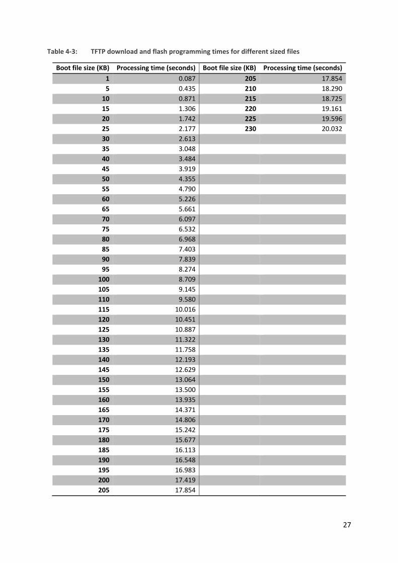
4.3.3.2 TFTP processing speed
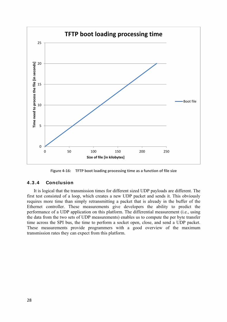
Many programs can be written for the MSP430, hence the size of the programs can differ. Since the bit rate for the TFTP and flash programming is known, we can compute the time required to download and store any sized file. Table 4-3 shows this for different sized files starting from 1 KB to 230 KB (this is the upper bound because a maximum of 229 KB are available in the Flash memory as some of the space is taken by the TFTP boot program). Figure 4-16 shows this data as chart. Note that this table and figure were computed assuming that the time for TFTP and programming the flash is linear increase in the file size.
0
1000
2000
3000
4000
5000
6000
0 1 2 3
Data
[in
bits
]
Time [in seconds]
TFTP process bit rate
TFTP data
27
Table 4-3: TFTP download and flash programming times for different sized files
Boot file size (KB) Processing time (seconds) Boot file size (KB) Processing time (seconds)1 0.087 205 17.8545 0.435 210 18.290
10 0.871 215 18.72515 1.306 220 19.16120 1.742 225 19.59625 2.177 230 20.03230 2.61335 3.04840 3.48445 3.91950 4.35555 4.79060 5.22665 5.66170 6.09775 6.53280 6.96885 7.40390 7.83995 8.274
100 8.709105 9.145110 9.580115 10.016120 10.451125 10.887130 11.322135 11.758140 12.193145 12.629150 13.064155 13.500160 13.935165 14.371170 14.806175 15.242180 15.677185 16.113190 16.548195 16.983200 17.419205 17.854
28
Figure 4-16: TFTP boot loading processing time as a function of file size
4.3.4 Conclusion
It is logical that the transmission times for different sized UDP payloads are different. The first test consisted of a loop, which creates a new UDP packet and sends it. This obviously requires more time than simply retransmitting a packet that is already in the buffer of the Ethernet controller. These measurements give developers the ability to predict the performance of a UDP application on this platform. The differential measurement (i.e., using the data from the two sets of UDP measurements) enables us to compute the per byte transfer time across the SPI bus, the time to perform a socket open, close, and send a UDP packet. These measurements provide programmers with a good overview of the maximum transmission rates they can expect from this platform.
0
5
10
15
20
25
0 50 100 150 200 250
Tim
e ne
ed to
pro
cess
the
file
[in se
cond
s]
Size of file [in kilobytes]
TFTP boot loading processing time
Boot file

29
5 Conclusions and future work This chapter presents conclusions based on the performed tasks and analysis. The initial
goals of the project and our achievements are compared. Furthermore, some suggestions are made of future work. Finally, several economic, social, environmental, and ethical reflections are given.
5.1 General conclusions The main objectives of this project were to fix the TFTP boot loading problem and to
evaluate the Microchip TCP/IP stack when using a TI MSP430 MCU and a Microchip ENC28J60 Ethernet controller connected via SPI. The first goal, namely TFTP boot loading now works. The TFTP boot loader program correctly downloads a program into flash memory from a TFTP server. However, some additional improvements could have been made. Since the board has two programmable buttons and one is used for resetting the motherboard. Pressing this button resets the motherboard and downloads an updated version of the file provided by the TFTP server -if there is such a file available on the TFTP server. The second button could have been configured as a soft reset button. When this second button is pushed, the motherboard could simply restart the already loaded program. Unfortunately, I was not able to realize this functionality. A hard reset can be done by simply unplugging and plugging the Ethernet cable. As I had already spent a lot of time to solve the basic boot loading problem I decided not to spend more time introducing this new functionality.
The second goal of this project was to evaluate the Microchip TCP/IP stack’s performance. Several measurements and calculations were done. However, it is possible to do more measurements and calculations. I focused on UDP transmission from the MCU to the PC’s Ethernet controller. Additionally, I calculated how fast a TFTP boot file is processed by the embedded board. In the future, it would be interesting to measure the Transmission Control Protocol (TCP) protocols throughput. Since I was close to the deadline for this project, I decided to skip measurements of TCP.
This was my first experience with hardware, thus I learned a lot about microcontrollers and how to program them. Before this project, my knowledge of the C programming language was very limited. This lead to many struggles when programming the MCU. However, by reading datasheets I gained insight into the MSP430 MCU family. Furthermore, the extensive use of Wireshark motivated me to learn how to use this handy tool much better than I could before this project. Additionally, I inspected every detail of the TFTP protocol and learned how to create UDP packets in the MCU.
If I was to do this project all over again, I would probably start with the IP stack evaluation instead of fixing the TFTP issue. I feel that I could have done a much more extensive evaluation of the IP stack. Unfortunately, I lost a lot of time trying to fix the TFTP problem. However, I would probably not have learned as much as I did about how to program microcontrollers and how the IP stack works at a low level.
My advice to future contributors to this project is to make much more extensive use of the Ethernet controller's buffer when possible. According to my measurements it is possible to decrease the time needed to generate and send UDP packets if one were to make fuller use of the capabilities of this Ethernet controller. Of course, a clear task is to evaluate the TCP module of this IP stack. Additionally, carefully reading the data sheets and documentation can save a lot of time and annoyance.

30
5.2 Future work As discussed earlier, evaluation of the TCP functionality of the IP stack has not been done,
but clearly should be done. Additionally, it is possible to do many interesting calculations based on the existing observations. In this way the capabilities of the motherboard will be much better documented for future developers.
Another area of tests and measurements is to determine the maximum rate at which data contained in UDP packets can be transferred from the PC to the MCU. As the current measurements only consider traffic going in the other direction.
Moreover, the programmable buttons can be used to better effect. It is recommended that both hard and soft reset functionalities be implemented.
A potentially interesting idea is to develop a monitoring program for the network, which uses this embedded platform. A program could monitor a number of these boards to see if they are active or not and to detect failures as soon as possible. A benchmark tool could be implementing to help developers measure and analyze the throughput and latency of different nodes in the network. Furthermore, the TFTP boot loader has an important place in facilitating future tests and measurement. In summary it is it up to future developers to exploit this Swiss knife of a lower power PoE networked computing platform.
5.3 Required reflections This project reduces costs by exploiting the TFTP boot loading functionality. Future users
can develop programs with a code size larger than 16 KB. This can save a developer a lot of money, considering that a node locked single user license of CCS costs US$495.00. This can be a big gain for an organization that needs, for example, to support 50 developers which would otherwise cost US$19,994.00*.
Avoiding these costs raises the question if it is ethical to do this or not. Some people would say that this is ethical because the user does not load program code larger than 16 KB via the IDE. While others might say it is not because the user should pay the company for the use of the IDE. It is up to the user to decide if the usage of TFTPboot loading system is ethical or not. It should also be noted that the TFTPboot loading system can be used with code compiled using other development tools.
While carrying out this project no environmental or sustainability issues were encountered. However, in retrospect the use of the TFTP boot loader does contribute to sustainability as it allows the same hardware to easily be reprogrammed for many different uses – in fact, the same hardware can be potentially dynamically used for different purposes at different times (the maximum number of times that the flash memory can be reprogrammed will set an upper limit on this reuse). Furthermore, this project does not seem to have a positive or negative effect on society, although it facilitates the development of new applications that might have positive or negative effects on society.
*Given the current price for CCS at http://www.ti.com/tool/ccstudio.

31
References [1] A. López and F. J. Sánchez, “Exploiting Wireless Sensors: A gateway for 868 MHz
sensors,” Master’s thesis, KTH Royal Institute of Technology, School of Information and Communication Technology, Stockholm, Sweden, 2012.
[2] “TI MSP430F5437A Datasheet.” . [3] “ENC28J60 Data Sheet.” . [4] J. Lara Peinado, “Minding the spectrum gaps: First steps toward developing a distributed
white space sensor grid for cognitive radios,” Master’s thesis, KTH Royal Institute of Technology, School of Information and Communication Technology, Stockholm, Sweden, 2013.
[5] “SPI Block Guide V03.06.” . [6] P. M. in D. Mah, “What does the new Power over Ethernet standard mean for IT pros?,”
TechRepublic. [Online]. Available: http://www.techrepublic.com/blog/data-center/what-does-the-new-power-over-ethernet-standard-mean-for-it-pros/. [Accessed: 23-May-2014].
[7] “IEEE SA - 802.3af-2003.” [Online]. Available: http://standards.ieee.org/findstds/standard/802.3af-2003.html. [Accessed: 25-May-2014].
[8] S. Alexander and R. Droms, “DHCP Options and BOOTP Vendor Extensions,” Internet Request for Comments, vol. RFC 2132 (Draft Standard), Mar. 1997.
[9] J. Alba Tormo Peiró,, “Spectrum sensing based on specialized microcontroller based white space sensors: Measuring spectrum occupancy using a distributed sensor grid,” Master’s thesis, KTH, School of Information and Communication Technology, Communication Systems, Stockholm, Sweden, 2013.
[10] R. Karim and H. Al-Fakhri, “Smart Door Lock : A first prototype of a networked power lock controller with an NFC interface.,” Bachelor’s Thesis, KTH, School of Information and Communication Technology, Communication Systems, Stockholm, Sweden, 2013.
[11] R. Droms, “Dynamic Host Configuration Protocol,” Internet Request for Comments, vol. RFC 2131 (Draft Standard), Mar. 1997.
[12] J. Postel, “Internet Protocol,” Internet Request for Comments, vol. RFC 791 (INTERNET STANDARD), Sep. 1981.
[13] J. Postel, “User Datagram Protocol,” Internet Request for Comments, vol. RFC 768 (INTERNET STANDARD), Aug. 1980.
[14] K. R. Sollins, “TFTP Protocol (revision 2),” Internet Request for Comments, vol. RFC 783, Jun. 1981.
[15] K. R. Sollins, “The TFTP Protocol.” [Online]. Available: http://www.rfc-editor.org/ien/ien133.txt. [Accessed: 23-May-2014].
[16] K. Sollins, “The TFTP Protocol (Revision 2),” Internet Request for Comments, vol. RFC 1350 (INTERNET STANDARD), Jul. 1992.
[17] “TL2575HV-ADJ | Step-Down (Buck) Converter | Converter (Integrated Switch) | Description & parametrics.” [Online]. Available: http://www.ti.com/product/tl2575hv-adj. [Accessed: 23-May-2014].
[18] “TPS2375 | Powered Device | Power Over Ethernet (PoE)/LAN Solutions | Description & parametrics.” [Online]. Available: http://www.ti.com/product/tps2375. [Accessed: 23-May-2014].
[19] “IEEE-SA -IEEE Get 802 Program - 802.3: Ethernet.” [Online]. Available: http://standards.ieee.org/about/get/802/802.3.html. [Accessed: 23-May-2014].
[20] “Introduction to JTAG | Embedded.” [Online]. Available: http://www.embedded.com/electronics-blogs/beginner-s-corner/4024466/Introduction-to-JTAG. [Accessed: 23-May-2014].

32
[21] “Texas Instruments MSP430 JTAG header pinout.” [Online]. Available: http://www.jtagtest.com/pinouts/msp430. [Accessed: 23-May-2014].
[22] “ProCurve Switch 2626 (J4900B) specifications - HP Products and Services Products.” [Online]. Available: http://h10010.www1.hp.com/wwpc/ca/en/sm/WF06b/12136296-12136298-12136298-12136298-12136316-12136318-31539227.html?dnr=2. [Accessed: 23-May-2014].
[23] “Dell OptiPlex GX620.” [Online]. Available: http://www.dell.com/support/drivers/us/en/19/Product/optiplex-gx620. [Accessed: 23-May-2014].
[24] “openSUSE.” [Online]. Available: http://en.opensuse.org/Main_Page. [Accessed: 23-May-2014].
[25] “Realtek RTL8139 Ethernet controller.” [Online]. Available: http://www.realtek.com.tw/products/productsView.aspx?Langid=1&PFid=6&Level=5&Conn=4&ProdID=16. [Accessed: 28-May-2014].
[26] “MSP430 USB Debugging Interface - MSP-FET430UIF - TI Software Folder.” [Online]. Available: http://www.ti.com/tool/msp-fet430uif. [Accessed: 23-May-2014].
[27] “Wireshark · Go Deep.” [Online]. Available: http://www.wireshark.org/. [Accessed: 23-May-2014].
[28] “Tcpdump/Libpcap public repository.” [Online]. Available: http://www.tcpdump.org/. [Accessed: 23-May-2014].
[29] “Eclipse - The Eclipse Foundation open source community website.” [Online]. Available: http://www.eclipse.org/. [Accessed: 23-May-2014].
[30] “CCS - Texas Instruments Wiki.” [Online]. Available: http://processors.wiki.ti.com/index.php/Download_CCS. [Accessed: 23-May-2014].
[31] “Portal:YaST - openSUSE.” [Online]. Available: http://en.opensuse.org/Portal:YaST. [Accessed: 23-May-2014].
[32] R. Karim and H. Al-Fakhri, “Smart Door Lock : A first prototype of a networked power lock controller with an NFC interface.,” Bachelor’s Thesis, KTH, School of Information and Communication Technology, Communication Systems, Stockholm, Sweden, 2013.
[33] J. L. Peinado, “Mind-the-gaps GitHub,” GitHub. [Online]. Available: https://github.com/cazulu/mind-the-gaps. [Accessed: 23-May-2014].
[34] “TI-TXT file format -srec_ti_txt Linux man page.” [Online]. Available: http://linux.die.net/man/5/srec_ti_txt. [Accessed: 23-May-2014].
[35] H. Schlunder, “UDP Performance Test microcontrollers.” [Online]. Available: https://github.com/exosite-garage/mcp_dv102412_cloud. [Accessed: 23-May-2014].
[36] “Microchip TCP/IP Stack Help.” .
33
Appendix A
GitHub repository
All the source code and related documents of this project are publicly available on a GitHub repository. The link to this repository is https://github.com/kekovski/MSP430 and consists of several folders:
Analysis: Calculations and charts based on the measurements
Captures: All the Wireshark captures
The source code is divided in two parts
• Analyze: Program for IP stack evaluation
• Updated version of a TFTP program loader for MSP430
Figures: All of the used figures in the final report