tg3 use of nuclear density meters (ndm) - cetanz technical guideline (tg) page 2 of 17 tg3 – use...
TRANSCRIPT

CETANZ Technical Guideline (TG) Page 1 of 17
TG3 – Use of Nuclear Density Meters (NDM)
TG Number: TG3 Authors: Brigitte Sargent Steven Anderson
Revision number: 1 Issue Date: May 2017
1 NTRODUCTION
This guideline aims to provide consistency amongst CETANZ members performing in NDM tests within a New Zealand Testing Laboratory context. The CETANZ technical working group has discussed and consulted with members to provide this best practice guideline.
This information is supplementary to the following test methods for soil and aggregates:
a) NZS4407: 2015 Methods of sampling and testing road aggregate: Test 4.2. The field water content and field dry density of compacted materials - method using a nuclear moisture-density gauge in - direct transmission.
b) NZS4407: 2015 Methods of sampling and testing road aggregate: Test 4.3 The field water content and field dry density of compacted materials - method using a nuclear moisture-density gauge - backscatter mode.
c) ASTM D6938-15 Standard test method for in-place density and water content of soil and soil-aggregate by nuclear methods (Shallow depth)
This information is supplementary to the following test methods for asphalt pavements:
a) AS/NZS 2891.14.2:2013 Methods of sampling and testing asphalt Method 14.2: Field density tests—Determination of field density of compacted asphalt using a nuclear thin-layer density gauge
b) ASTM D2950/D2950M-14 Standard Test Method for Density of Bituminous Concrete in Place by Nuclear Methods
This guideline is also supplementary to:
Manufacturers’ handbooks and/or Instruction Manuals
Radiation Safety Regulation 2016 http://www.legislation.govt.nz/regulation/public/2016/0303/4.0/DLM7049344.html
Code of Safe Practice 15 (CSP15)for the use of Nuclear Density Meters – Office of Radiation Safety (ORS), Ministry of Health, New Zealand
Guidance Notes 15 (GN15), Safe Practice for the Use of Nuclear Density Meters - Office of Radiation Safety (ORS), Ministry of Health, New Zealand
When performing tests, the above documents take precedence over this guide.
2 SAFETY
This equipment is radioactive and therefore there is specific legislation covering all aspects of its purchase, storage, use, transportation and disposal. Only a registered licensee or trained user operating under the control of a licensee at that location can purchase, use or hire this equipment. The Code of Safe Practice 15 (CSP15) for the use of Nuclear Density Meters and Guidance Notes 15 (GN15), Safe Practice for the Use of Nuclear Density Meters should apply at all times.

CETANZ Technical Guideline (TG) Page 2 of 17
TG3 – Use of Nuclear Density Meters (NDM)
TG Number: TG3 Authors: Brigitte Sargent Steven Anderson
Revision number: 1 Issue Date: May 2017
An NDM has the following two radioactive sources:
Caesium 137 emitting gamma radiation; and
Americium Beryllium emitting alpha and neutron radiation.
The gamma radiation is shielded by a tungsten sliding shutter. When not in use the nuclear density meter handle should be secured at the highest point and locked (otherwise known as the “safe” position). In this position the tungsten sliding shutter shields the gamma source.
The Americium Beryllium is not shielded, thus the nuclear density meter is always emitting slow neutrons and alpha rays even when in the “safe” position. This should be considered when the equipment is not in use, e.g. in vehicles or in storage.
When in use, the handle should be in the “safe” position at all times, except when taking a reading. The handle should be returned to the “safe” position immediately after each test and the source rod should never be touched or pointed towards anyone.
Personal dose monitoring is required if the gamma source is exposed for more than 2 hours per week (i.e. 120 x 1 minute samples) and the user is within 1m of the nuclear density meter. Film monitoring in New Zealand has revealed that users do sometimes receive a measurable dose.
A special service licence is required if any maintenance beyond what is described in the user manual. It is expected that only a licensee would dismantle the shutter mechanism for cleaning and inspection.
Underground services should be checked before commencing testing.
Road transport guidance is given at:
http://www.health.govt.nz/our-work/radiation-safety/transporters-radioactive-material/road-transport-radioactive-material
Important Note – There are roads and tunnels where an NDM cannot be transported – contact your supplier for advice.
CETANZ Technical Guideline (TG) Page 3 of 17
TG3 – Use of Nuclear Density Meters (NDM)
TG Number: TG3 Authors: Brigitte Sargent Steven Anderson
Revision number: 1 Issue Date: May 2017
3 TYPES AND LOCATION OF RADIOACTIVE SOURCES
The nuclear density meter has two radioactive sources:
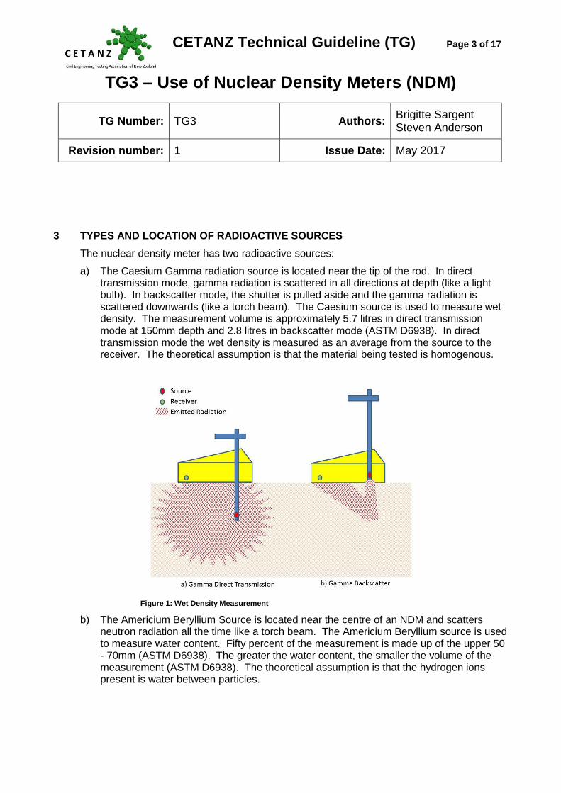
a) The Caesium Gamma radiation source is located near the tip of the rod. In direct transmission mode, gamma radiation is scattered in all directions at depth (like a light bulb). In backscatter mode, the shutter is pulled aside and the gamma radiation is scattered downwards (like a torch beam). The Caesium source is used to measure wet density. The measurement volume is approximately 5.7 litres in direct transmission mode at 150mm depth and 2.8 litres in backscatter mode (ASTM D6938). In direct transmission mode the wet density is measured as an average from the source to the receiver. The theoretical assumption is that the material being tested is homogenous.
Figure 1: Wet Density Measurement
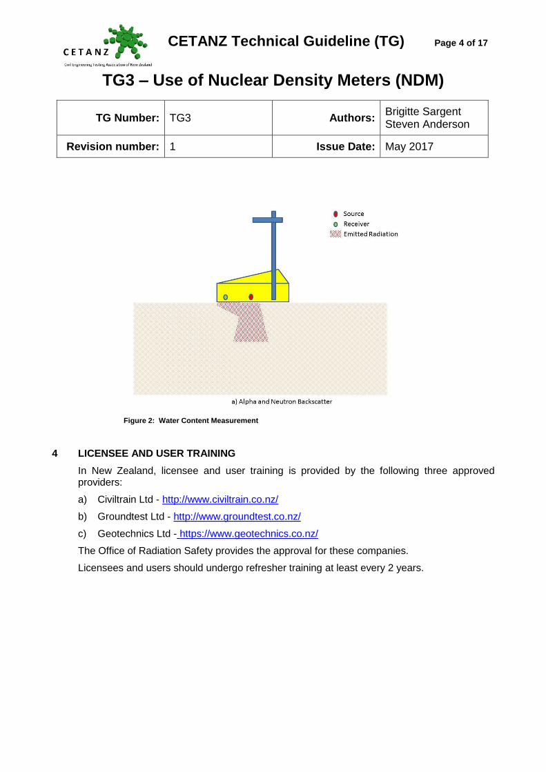
b) The Americium Beryllium Source is located near the centre of an NDM and scatters neutron radiation all the time like a torch beam. The Americium Beryllium source is used to measure water content. Fifty percent of the measurement is made up of the upper 50 - 70mm (ASTM D6938). The greater the water content, the smaller the volume of the measurement (ASTM D6938). The theoretical assumption is that the hydrogen ions present is water between particles.
CETANZ Technical Guideline (TG) Page 4 of 17
TG3 – Use of Nuclear Density Meters (NDM)
TG Number: TG3 Authors: Brigitte Sargent Steven Anderson
Revision number: 1 Issue Date: May 2017
Figure 2: Water Content Measurement
4 LICENSEE AND USER TRAINING
In New Zealand, licensee and user training is provided by the following three approved providers:
a) Civiltrain Ltd - http://www.civiltrain.co.nz/
b) Groundtest Ltd - http://www.groundtest.co.nz/
c) Geotechnics Ltd - https://www.geotechnics.co.nz/
The Office of Radiation Safety provides the approval for these companies.
Licensees and users should undergo refresher training at least every 2 years.

CETANZ Technical Guideline (TG) Page 5 of 17
TG3 – Use of Nuclear Density Meters (NDM)
TG Number: TG3 Authors: Brigitte Sargent Steven Anderson
Revision number: 1 Issue Date: May 2017
5 RADIATION SAFETY PLAN
All companies purchasing or hiring an NDM are required to have a Radiation Safety Plan (RSP) as detailed in the “Radiation Safety Act 2016 Section 18 Radiation Safety Plan”.
Assistance with writing an RSP can be provided by:
a) Civiltrain Ltd - http://www.civiltrain.co.nz/ b) Groundtest Ltd - http://www.groundtest.co.nz/ c) Geotechnics Ltd -https://www.geotechnics.co.nz/
6 THE PURPOSE OF DENSITY AND WATER CONTENT TESTING
The level of compaction of soil, aggregate or bitumen in Civil Engineering applications is determined by density and water content testing. Typically a high dry density implies a high level of compaction and strength of the material tested in-situ. The material is also tested in the laboratory to determine the maximum dry density (MDD) and optimum water content. If the in-situ material is compacted to the maximum dry density and optimum water content, it is more likely to remain durable under the design load (assuming the design calculations and assumptions are correct).
7 WHY USE A NUCLEAR DENSOMETER?
An NDM test is a rapid, repeatable way of determining wet density and water content. Alternative methods such as core cutters, sand replacement and water replacement are slower in the field and more disruptive to site operations.
8 HANDLE AND SHUTTER MECHANISM CHECKS
The NDM handle should be easy to unlock and slide up and down. If it is stiff, servicing by a trained service technician should be arranged.
With the handle in the “safe” position, check that the tungsten sliding shutter is shut firmly and not open. Long term exposure to the base and physical contact with this part of the gauge should be avoided.
9 PRE-OPERATIONAL CHECKS
It is important to warm the electronics of an NDM before using it. A gauge should be turned on before leaving for site and returned it to its case before driving to a job site, allowing a minimum of 10 minutes to warm up.
The presence of moisture inside of the instrument cavity will cause malfunctions of the gauge. Consequently they should be stored in a warm dry place and not be used in the rain.

CETANZ Technical Guideline (TG) Page 6 of 17
TG3 – Use of Nuclear Density Meters (NDM)
TG Number: TG3 Authors: Brigitte Sargent Steven Anderson
Revision number: 1 Issue Date: May 2017
The gauge should not be cleaned with hydrocarbon products, because these could be incorrectly detected as moisture by the gauge.
10 STANDARD COUNTS, VERIFICATION AND CALIBRATION
Standard counts are performed to check the machine’s performance and reduce the impact of background radiation of different material types and different sites. At a minimum, daily standard counts should be taken at the start of each day and in the same location before travelling to site. If these values are outside of the acceptable limits (refer section 10.2 of this document), the NDM requires servicing and recalibration. When on site, a standard count should be taken on the material to be tested and then again when testing a different material or at a different site.
An NDM is an electronic device that is calibrated using dry metal, polymer and natural rock blocks – all of which do not contain soil or water. It is therefore essential to perform these early correlation tests against other physical methods, such as oven dry water contents, sand replacement tests, core cutters or water replacement tests. It is important to perform correlation tests on every site because there are materials that may cause irregular water content readings, such as materials with hydrogen ions (e.g. recycled concrete), large quantities of lime and cement, oil and/or bitumen. Wet density can also sometimes be affected by certain soil types.
10.1 Standard Counts
Each gauge has a dedicated standard block, the serial number of which matches the serial number on the gauge. As the gauge is calibrated to its block, it is important to always use matching blocks and gauges. Types of standard counts:
a) Pre-operation daily check - The daily operation of an NDM can be monitored by performing standard counts in exactly the same location without any other objects coming into the calibration environment between successive counts. This can be in a specific location inside the laboratory away from any influencing factors such as vertical surfaces or other NDMs. It could also be done at one specific location on a project. Drifts of no more than 1% for the density count and 2 % for the moisture count would be expected.
b) On-site standard counts - The standard count allows for the exponential deterioration of the nuclear sources and for background radiation of the site and test materials. Therefore it is essential to perform a standard count on every site and on different material types (i.e. clay, silt, basecourse). Drifts of no more than 1% for the density count and 2 % for the moisture count would be expected
The Moisture and Density standards should be logged in a field book stating the date and readings, location and the test material. This builds up a history over a period of time and can identify if the machine is faulty.
CETANZ Technical Guideline (TG) Page 7 of 17
TG3 – Use of Nuclear Density Meters (NDM)
TG Number: TG3 Authors: Brigitte Sargent Steven Anderson
Revision number: 1 Issue Date: May 2017
Over time the counts will slowly reduce for a particular site and material type, but they can change by 5 to 10% between different sites and materials. If, however, the counts change dramatically on previously tested material or a laboratory reference pad, they indicate a system malfunction or operator error.
Standard counts should be performed at least 9m away from other radioactive devices (ASTM D6938), and at least 5m away from any vertical surfaces such as people, heavy machinery, buildings or vehicles. These can significantly affect the density count when in backscatter mode and to a lesser extent, the moisture count.
When measurements are taken in trenches, the standard count should be performed in the trench in “trench” mode. This minimises the affects mentioned above.
10.2 Statistical Counts
The statistical count checks that the machine is functioning properly. The statistical count measures one minute counts over a predetermined time period and will also provide a density count and moisture count. Statistical counts should be performed at least every three months, if a problem is suspected or as company quality assurance dictates.
Humboldt NDMs have a 16 minute count. The density count (DC) and moisture count (MC) which are called R values, should fall within 0.6 and 1.4 which indicates the gauge is stable. If the values are outside the range of 0.5 and 1.5, the gauge requires service.
Troxler NDMs have a 20 minute count with the capability to also perform a drift test. The density count (DC) and moisture count (MC) should fall within 0.17 and 0.33. If the counts fail, the test should be repeated. If it fails two out of three retests then the gauge requires service.
10.3 Verification checks
NDMs should be verified on a regular basis to confirm that accurate results are being returned. Verification should include:
a) Regular checks in the laboratory on a specimen of known density, such as a natural rock or concrete block.
b) On site confirmation that the material under test is not biasing gauge results, such as materials with chemically bound water or mineralogy.
c) Confirmation of gauge accuracy when testing materials fall outside of the calibration range of the gauge.
These checks can be done using the two calibration methods from NZS4407:1991 Test 4.2.3 and Test 4.2.4 (Withdrawn by Standards New Zealand and not replaced). Test method 4.2.3 is for correlating an NDM to a particular material type encountered on a site or project. Test 4.2.4 is for calibrating an NDM against standard blocks. Some owners have their own calibration blocks for regular internal checking of NDMs. The frequency of checks is

CETANZ Technical Guideline (TG) Page 8 of 17
TG3 – Use of Nuclear Density Meters (NDM)
TG Number: TG3 Authors: Brigitte Sargent Steven Anderson
Revision number: 1 Issue Date: May 2017
dependent on the frequency of use.
10.4 Full External Calibration
As the radioactive sources are decaying continuously and the electronics are subject to drift, calibration is essential. A calibrated NDM gives a user confidence that the readings are reliable as long as the other requirements of the test procedure are followed.
It is recommended that all NDMs are calibrated for density and moisture by an IANZ accredited calibration service. Currently the calibration procedure is based on NZS4407:1991 Test 4.2.4. (Withdrawn by Standards New Zealand and not replaced).
An NDM is calibrated using dry metal, polymer and natural rock blocks over a density range. If field test results are outside this range, a disclaimer should be entered in the test report unless correlation testing proves otherwise. The density range for Humboldt NDMs is 1728kg/m3 to 2756kg/m3 and the range for Troxler NDMs is 1700kg/m3 to 2650kg/m3.
The moisture content is also calibrated on a poly/aluminium block. For Humboldt NDMs this is done at an equivalent 499kg/m3 of water and for Troxler NDMs it is done at an equivalent 508kg/m3 of water.
Calibration Providers in New Zealand are:
a) The Measurement and Calibration Centre - http://www.themcc.co.nz/
b) Groundtest Ltd - http://www.groundtest.co.nz/
11 SELECTION OF A TEST LOCATION
Representative selection of a test location is important. Sometimes a testing frequency may be specified by the contract documents e.g. test on a 10m grid, test every 20m length along a single carriageway lane or perform 5 tests per 1000m2. The selection process must be as random as possible and care must be taken not to select the worst or best test locations.
12 WHEN TO USE BACKSCATTER OR DIRECT TRANSMISSION
Typically, if the direct transmission drive pin can be driven into materials (such as soil) easily, a direct transmission test should be performed. Backscatter is usually performed on aggregates, asphalt and stabilised layers.
13 TEST METHODS
In New Zealand, the test standards generally referred to are:
a) NZS4407:2015 Tests 4.2 and 4.3, ASTM D6938, for aggregates and soils b) AS/NZS2891.1.14.2 or ASTM D2950 for asphalt pavements.

CETANZ Technical Guideline (TG) Page 9 of 17
TG3 – Use of Nuclear Density Meters (NDM)
TG Number: TG3 Authors: Brigitte Sargent Steven Anderson
Revision number: 1 Issue Date: May 2017
13.1 NZS4407:2015
New Zealand Standard NZS4407:2015 includes the following two test methods relating to NDMs:
a) NZS4407: 2015 Methods of sampling and testing road aggregate: Test 4.2. The field water content and field dry density of compacted materials - method using a nuclear moisture-density gauge in - direct transmission.
b) NZS4407: 2015 Methods of sampling and testing road aggregate: Test 4.3 The field water content and field dry density of compacted materials - method using a nuclear moisture-density gauge - backscatter mode.
Surface preparation is emphasised but no limit is placed as to the amount of preparation is required except to state that the preparation material should not form an added layer.
13.2 ASTM D6938
ASTM D6938 is a very simple and comprehensive test method and, being an American Standard, is reviewed at least every 7 years. It provides a significant amount of good background information about the test. The method lists interferences such as chemical composition of material, non-homogenous soils and surface texture. It also highlights that backscatter results can be influenced more by the density and water content of material in close proximity to the surface.
ASTM D6938 does not highlight that standardisation in one place in the laboratory is useful, but it does mention standardising at the start of each day. The method also does not mention standard counts for different sites or materials.
It contains a detailed section on surface preparation, stating that the maximum void beneath the gauge should not exceed 3mm. It recommends using native fines or fine sand, not to exceed 3mm of filler nor fill more than 10% of the base area of the gauge.
The test method discusses interferences and provides a very clear test procedure.
The test method also details the likely depth of tests with respect to the water content of the soil and that water content samples should be taken from directly under the gauge. It also states that verification samples taken from under the gauge should be 200mm in diameter and taken at a depth of 75mm for backscatter mode. When in direct transmission mode, samples should be taken at a depth equivalent to the probe depth. The annexes detail calibration and precision.
13.3 AS/NZS 2891.14.2:2013
This is the designated asphalt testing method in the new draft of NZTA M10 specification.

CETANZ Technical Guideline (TG) Page 10 of 17
TG3 – Use of Nuclear Density Meters (NDM)
TG Number: TG3 Authors: Brigitte Sargent Steven Anderson
Revision number: 1 Issue Date: May 2017
The gauge must be calibrated according to AS2891.14.3 at least once every 2 years.
The standard counts are to be performed before (daily) and after (site specific, therefore one per site) arriving on site. The standard count methods are detailed in Appendix A and some calculations are involved to determine the daily upper and lower limits. When performing standard counts, the same location should be used for consistency purpose and it must be at least 1m away from any vertical surface. The test method also requires the gauge function and density system consistency checks.
At the start of a job, the offset of the gauge is should be determined according to the Appendix B.
Prepare a test surface by placing sand on the test site, then use a steel straightedge to spread the sand to fill small surface voids, leaving the tops of the surface aggregate exposed. The sand shall not form an added layer on the surface. The extent of the sand area is not mentioned.
The count time is at least 4min and the density correction formula is available for thin layers of asphalt between 25mm to 35mm.
Overall this method has a lot more detail in the use of an NDM.
13.4 ASTM D2950/D2950M-11
This is also a designated asphalt test methods in the new draft of NZTA M10 specification.
This method is similar to the Australian method in that it also states that test results are relative therefore a conversion factor must be established using at least 7 core results and correlated to the NDM results. A new conversion factor must be established each time there is a change in the material. In manufacturer’s manual the offset should be determined for each shift.
The method points out that many factors interfere with test results such as; material chemical composition (e.g. atomic number over 20 may cause high results), material in close proximity, overlay material, the surface roughness, oversize aggregate and volume being tested. Calibration of the gauge is required at least once a year. A daily standard count (standardisation) normally of 4min is used if the test time is 1min. The allowable error from average of last 4 is calculated by a formula (approximately 100 kg / m3 or around 4% of the standard count, whereas this value is 1% in New Zealand). The gauge is required to be left on all day for consistency. The gauge cannot be used within 250mm of any vertical surfaces.
CETANZ Technical Guideline (TG) Page 11 of 17
TG3 – Use of Nuclear Density Meters (NDM)
TG Number: TG3 Authors: Brigitte Sargent Steven Anderson
Revision number: 1 Issue Date: May 2017
Maximum contact between the base of the instrument and the surface of the material under test is critical. No gap will be more than 6mm between the gauge and surface being tested. Sand or native fines can be used to fill the gap. The annexes detail the calibration procedure.
14 OVERSIZE PARTICLES AND VOIDS
14.1 NZS 4407:2015 does not mention oversize particles or voids.
14.2 ASTM D6930 states that oversize material or voids may cause higher or lower density measurements. Where lack of uniformity is suspected, excavations should be made for visual examination and if oversize materials are present, a correction should be applied according to practice ASTM D4718 Correction of unit weight and water content for soils containing oversize particles. D4718 states that the oversize correction is only valid for soils where up to 40% is retained on a 4.75mm test sieve or up to 30% is retained on a 19mm test sieve. This tends to imply that only a GAP40mm material would comply.
Humboldt MFG Co and Troxler Electronic Laboratories Inc, both pointed the authors to ASTM D698 Laboratory compaction characteristics of soil using standard effort and D4718. D698 5.3.1 Oversize Fraction states that soil containing more than 30% oversize (>19mm) are a problem. They also state that field tests such as large in situ sand or water replacement are difficult and expensive to perform. They point readers to using a test fill, which is assumed to be a trial pad.
ASTM D6930 also states the measurement volume is approximately 5.7 litres in direct transmission mode at 150mm depth and 2.8 litres in backscatter mode. If this volume is converted into a 1:1 cylinder and we assume a particle diameter to cylinder diameter ratio of 5:1 then the maximum particle size is 38.7mm and 30.6mm respectively for direct transmission and backscatter. This reinforces the 40mm maximum particle size.
15 SURFACE PREPARATION
It is important that the material being tested is representative of both the moisture content and density of the fill. If a surface is left to dry then it may not represent the test material. If the material directly under the NDM is not homogeneous, the moisture content at the surface compared to the moisture content at depth will vary and the calculated dry density will be incorrect. When testing soil it is good practice to get a bulldozer or excavator to scrape the top 50 – 100mm off the test area. This can also save effort and time when finishing the test surface with hand tools. When testing aggregate, it must be checked that the surface has not been moistened (e.g. water truck) or allowed to dry excessively. If the surface is very “bony” or lacking fines, it may indicate the entire compacted aggregate is full of voids and therefore excess filling of voids could provide misleading results.
The better the preparation of the surface for backscatter measurements, the better the result
CETANZ Technical Guideline (TG) Page 12 of 17
TG3 – Use of Nuclear Density Meters (NDM)
TG Number: TG3 Authors: Brigitte Sargent Steven Anderson
Revision number: 1 Issue Date: May 2017
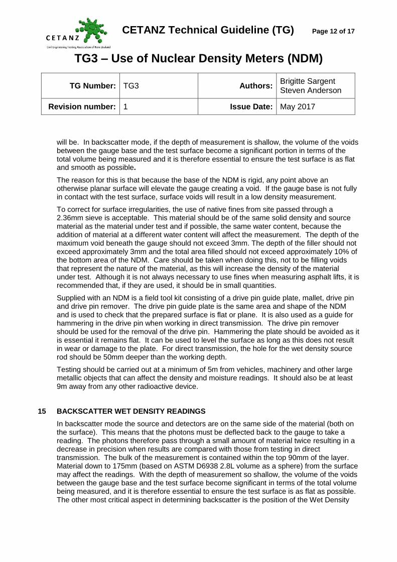
will be. In backscatter mode, if the depth of measurement is shallow, the volume of the voids between the gauge base and the test surface become a significant portion in terms of the total volume being measured and it is therefore essential to ensure the test surface is as flat and smooth as possible.
The reason for this is that because the base of the NDM is rigid, any point above an otherwise planar surface will elevate the gauge creating a void. If the gauge base is not fully in contact with the test surface, surface voids will result in a low density measurement.
To correct for surface irregularities, the use of native fines from site passed through a 2.36mm sieve is acceptable. This material should be of the same solid density and source material as the material under test and if possible, the same water content, because the addition of material at a different water content will affect the measurement. The depth of the maximum void beneath the gauge should not exceed 3mm. The depth of the filler should not exceed approximately 3mm and the total area filled should not exceed approximately 10% of the bottom area of the NDM. Care should be taken when doing this, not to be filling voids that represent the nature of the material, as this will increase the density of the material under test. Although it is not always necessary to use fines when measuring asphalt lifts, it is recommended that, if they are used, it should be in small quantities.
Supplied with an NDM is a field tool kit consisting of a drive pin guide plate, mallet, drive pin and drive pin remover. The drive pin guide plate is the same area and shape of the NDM and is used to check that the prepared surface is flat or plane. It is also used as a guide for hammering in the drive pin when working in direct transmission. The drive pin remover should be used for the removal of the drive pin. Hammering the plate should be avoided as it is essential it remains flat. It can be used to level the surface as long as this does not result in wear or damage to the plate. For direct transmission, the hole for the wet density source rod should be 50mm deeper than the working depth.
Testing should be carried out at a minimum of 5m from vehicles, machinery and other large metallic objects that can affect the density and moisture readings. It should also be at least 9m away from any other radioactive device.
15 BACKSCATTER WET DENSITY READINGS
In backscatter mode the source and detectors are on the same side of the material (both on the surface). This means that the photons must be deflected back to the gauge to take a reading. The photons therefore pass through a small amount of material twice resulting in a decrease in precision when results are compared with those from testing in direct transmission. The bulk of the measurement is contained within the top 90mm of the layer. Material down to 175mm (based on ASTM D6938 2.8L volume as a sphere) from the surface may affect the readings. With the depth of measurement so shallow, the volume of the voids between the gauge base and the test surface become significant in terms of the total volume being measured, and it is therefore essential to ensure the test surface is as flat as possible. The other most critical aspect in determining backscatter is the position of the Wet Density

CETANZ Technical Guideline (TG) Page 13 of 17
TG3 – Use of Nuclear Density Meters (NDM)
TG Number: TG3 Authors: Brigitte Sargent Steven Anderson
Revision number: 1 Issue Date: May 2017
Probe Rod. This position is set during maintenance and calibration to leave only enough room for a slip of paper to fit between the wet density probe rod and a flat surface. Even a small difference from this position affects the radioactive beam concentration and in turn significantly affects the density readings. When using an NDM the condition of the locating block in the handle should be checked for wear and the backscatter line on the index rod should line up with the top of the handle.
The following three conditions can affect the position of the wet density probe rod:
a) The depth of the index rod.
b) A worn locating block. (An NDM should always be carried in the “Safe” position, as this prevents premature wearing of the locating block.)
c) A loose locking handle mechanism.
16 DIRECT TRANSMISSION WET DENSITY READINGS
In direct transmission mode the source is inserted into the ground, and the radiation path is therefore directly through the material.
Direct transmission measurements also require a flat test surface, but are less influenced due to the direct transmission. In addition, a hole is required for the wet density probe rod. The procedure for surface preparation is the same as for backscatter measurements. The rod guide can first be used to level the surface, and then used as a guide for the drive pin. The drive pin should be driven 50mm deeper than the intended depth of measurement. The hole should be inspected to ensure it has remained intact and did not collapse during extraction as this will affect the density reading.
The gauge is then placed flat on the surface over the hole (without exposing the probe as this is unsafe) the wet density probe rod is lowered to the required depth. Next, the gauge is pulled towards the gas detection tubes, (opposing end) until the wet density probe rod is firmly against the side of the hole.
17 WATER CONTENT
The moisture neutron source is located centrally in the NDM body with its gas detection tube alongside it. Therefore it is always measuring moisture content in backscatter to about 70mm depth below the centre of the machine, whether in backscatter or direct transmission.
ASTM D6938 states that water content samples should be taken from directly under the gauge. It specifies that verification samples of 200mm in diameter should be taken at a depth of 75mm when in backscatter mode, and a depth equivalent to the probe depth when in direct transmission.
CETANZ Technical Guideline (TG) Page 14 of 17
TG3 – Use of Nuclear Density Meters (NDM)
TG Number: TG3 Authors: Brigitte Sargent Steven Anderson
Revision number: 1 Issue Date: May 2017
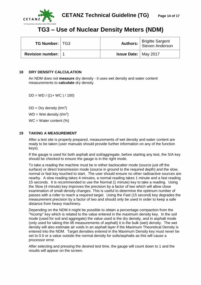
18 DRY DENSITY CALCULATION
An NDM does not measure dry density - it uses wet density and water content measurements to calculate dry density.
DD = WD / ((1+ WC ) / 100)
DD = Dry density (t/m3)
WD = Wet density (t/m3)
WC = Water content (%)
19 TAKING A MEASUREMENT
After a test site is properly prepared, measurements of wet density and water content are ready to be taken (user manuals should provide further information on any of the function keys).
If the gauge is used for both asphalt and soil/aggregate, before starting any test, the S/A key should be checked to ensure the gauge is in the right mode.
To take a reading the machine must be in either backscatter mode (source just off the surface) or direct transmission mode (source in ground to the required depth) and the slow, normal or fast key touched to start. The user should ensure no other radioactive sources are nearby. A slow reading takes 4 minutes, a normal reading takes 1 minute and a fast reading 15 seconds. It is recommended to use the Normal (1 minute) key to take a reading. Using the Slow (4 minute) key improves the precision by a factor of two which will allow close examination of small density changes. This is useful to determine the optimum number of passes with a roller to reach a required target. Using the Fast (15 second) key degrades the measurement precision by a factor of two and should only be used in order to keep a safe distance from heavy machinery.
Depending on the NDM it might be possible to obtain a percentage compaction from the “%comp” key which is related to the value entered in the maximum density key. In the soil mode (used for soil and aggregate) the value used is the dry density, and in asphalt mode (only used for taking thin lift measurements of asphalt) it is the bulk (wet) density. The wet density will also estimate air voids in an asphalt layer if the Maximum Theoretical Density is entered into the NDM. Target densities entered in the Maximum Density key must never be set to 0.0 or a value outside the normal density for soils/asphalts as this will cause a processor error.
After selecting and pressing the desired test time, the gauge will count down to 1 and the results will appear on the screen.
CETANZ Technical Guideline (TG) Page 15 of 17
TG3 – Use of Nuclear Density Meters (NDM)
TG Number: TG3 Authors: Brigitte Sargent Steven Anderson
Revision number: 1 Issue Date: May 2017
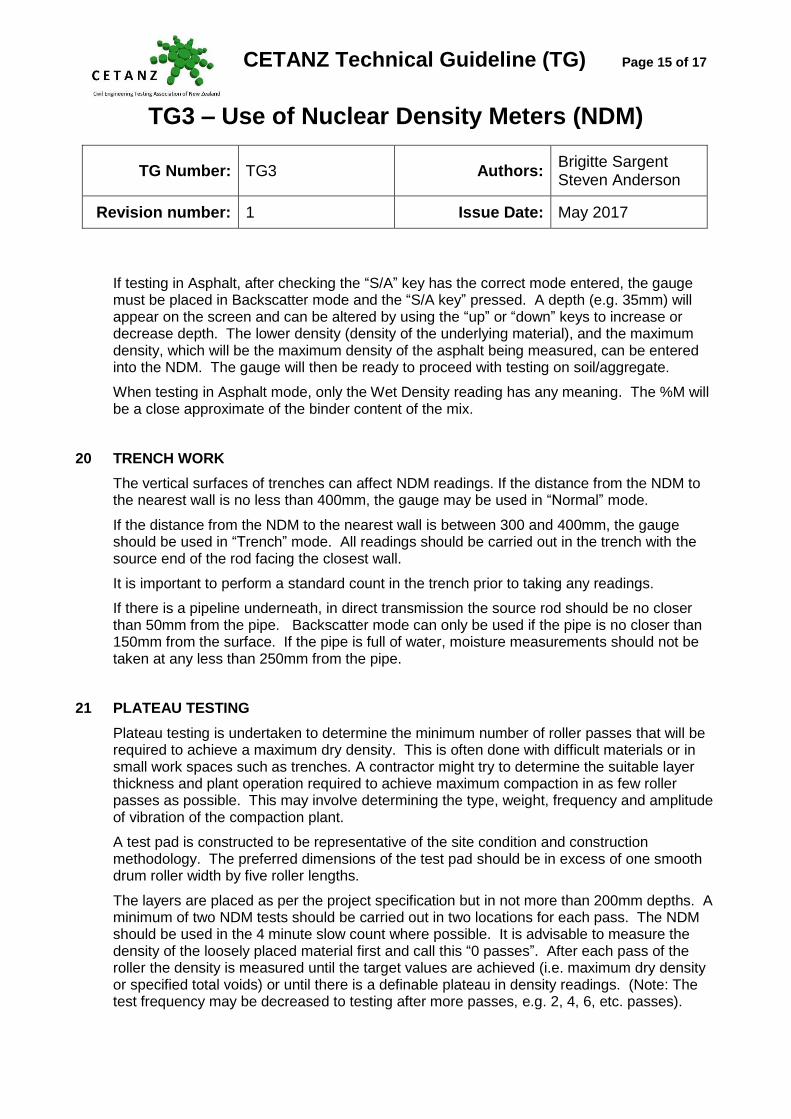
If testing in Asphalt, after checking the “S/A” key has the correct mode entered, the gauge must be placed in Backscatter mode and the “S/A key” pressed. A depth (e.g. 35mm) will appear on the screen and can be altered by using the “up” or “down” keys to increase or decrease depth. The lower density (density of the underlying material), and the maximum density, which will be the maximum density of the asphalt being measured, can be entered into the NDM. The gauge will then be ready to proceed with testing on soil/aggregate.
When testing in Asphalt mode, only the Wet Density reading has any meaning. The %M will be a close approximate of the binder content of the mix.
20 TRENCH WORK
The vertical surfaces of trenches can affect NDM readings. If the distance from the NDM to the nearest wall is no less than 400mm, the gauge may be used in “Normal” mode.
If the distance from the NDM to the nearest wall is between 300 and 400mm, the gauge should be used in “Trench” mode. All readings should be carried out in the trench with the source end of the rod facing the closest wall.
It is important to perform a standard count in the trench prior to taking any readings.
If there is a pipeline underneath, in direct transmission the source rod should be no closer than 50mm from the pipe. Backscatter mode can only be used if the pipe is no closer than 150mm from the surface. If the pipe is full of water, moisture measurements should not be taken at any less than 250mm from the pipe.
21 PLATEAU TESTING
Plateau testing is undertaken to determine the minimum number of roller passes that will be required to achieve a maximum dry density. This is often done with difficult materials or in small work spaces such as trenches. A contractor might try to determine the suitable layer thickness and plant operation required to achieve maximum compaction in as few roller passes as possible. This may involve determining the type, weight, frequency and amplitude of vibration of the compaction plant.
A test pad is constructed to be representative of the site condition and construction methodology. The preferred dimensions of the test pad should be in excess of one smooth drum roller width by five roller lengths.
The layers are placed as per the project specification but in not more than 200mm depths. A minimum of two NDM tests should be carried out in two locations for each pass. The NDM should be used in the 4 minute slow count where possible. It is advisable to measure the density of the loosely placed material first and call this “0 passes”. After each pass of the roller the density is measured until the target values are achieved (i.e. maximum dry density or specified total voids) or until there is a definable plateau in density readings. (Note: The test frequency may be decreased to testing after more passes, e.g. 2, 4, 6, etc. passes).

CETANZ Technical Guideline (TG) Page 16 of 17
TG3 – Use of Nuclear Density Meters (NDM)
TG Number: TG3 Authors: Brigitte Sargent Steven Anderson
Revision number: 1 Issue Date: May 2017
Compaction details and mode. i.e. “Vibration” or “Static” should be recorded for each pass.
Water contents and correlation tests should be conducted at the same time to check the NDM results. When performing the rolling, the compacting of the material should be visually observed and notes taken of crushing of larger fragments, weaving, spreading of the pad, etc.
A graph (refer Figure 3) of passes versus the parameters measured can then be plotted to show the maximum number of roller passes required to achieve the target value or the number of roller passes required until a plateau in the dry density results is achieved.
Figure 3: Plateau Test Graph
22 DISCLAIMER
The information in this publication is provided to encourage high standards within the civil engineering testing industry. The information is intended as a technical guide for CETANZ members only and in no way replaces New Zealand Standards or requirements of project specifications. CETANZ cannot accept any liability of any sort for unsatisfactory site or laboratory work carried out by companies who are members of CETANZ or organisations who claim to be following these guidelines. CETANZ assumes no responsibility for any loss which may arise from reliance on the guideline and disclaims all liability accordingly. Specialist and/or legal advice should always be sought on any specific problem or matter.
23 ACKNOWLEDGEMENTS
Thanks to the CETANZ Technical Committee for reviewing the document. Special thanks to
2.03
2.03
2.10
2.19
2.19
2.25
2.312.31
2.27
2.33
2.29
2.372.35
2.00
2.05
2.10
2.15
2.20
2.25
2.30
2.35
2.40
0 5 10 15 20 25 30 35
'DryDensity -Vibration'
Plateau Test - Density versus Cumulative Number Of Passes
Nu
clea
r D
ry D
ensi
ty (
t/m
3 )
Cumulative Number of Passes (No.)

CETANZ Technical Guideline (TG) Page 17 of 17
TG3 – Use of Nuclear Density Meters (NDM)
TG Number: TG3 Authors: Brigitte Sargent Steven Anderson
Revision number: 1 Issue Date: May 2017
Ineke Kriel of Geotechnics Ltd for formatting and editing the document.
24 REFERENCES
AS/NZS 2891.14.2:2013 Methods of sampling and testing asphalt, Method 14.2: Field density tests—Determination of field density of compacted asphalt using a nuclear thin-layer density gauge
ASTM D698 Laboratory compaction characteristics of soil using standard effort
ASTM D2950/D2950M Standard Test Method for Density of Bituminous Concrete in Place by Nuclear Methods
ASTM D4718 Correction of unit weight and water content for soils containing oversize particles
ASTMD6938 Standard Method for In-place Density and Water Content of Soil and Soil-Aggregate by Nuclear Methods (Shallow Depth)
Code of Safe Practice for the use of Nuclear Density Meters CSP15 – Office of Radiation Safety(ORS), Ministry of Health, New Zealand
http://www.health.govt.nz/our-work/radiation-safety/users-radiation/codes-safe-practice-radiation-use
Guidance Notes 15 (GN15), Safe Practice for the Use of Nuclear Density Meters - Office of Radiation Safety (ORS), Ministry of Health, New Zealand
http://www.health.govt.nz/our-work/radiation-safety/users-radiation/codes-safe-practice-radiation-use
NZS4407: 2015 Methods of sampling and testing road aggregate: Test 4.2. The field water content and field dry density of compacted materials - method using a nuclear moisture-density gauge in - direct transmission.
NZS4407: 2015 Methods of sampling and testing road aggregate: Test 4.3 The field water content and field dry density of compacted materials - method using a nuclear moisture-density gauge - backscatter mode.
NZS4407:1991 Test 4.2.3 Calibration of a Nuclear Surface Moisture - Density Gauge for Field Use (Withdrawn).
NZS4407:1991 Test 4.2.4 Calibration of a Nuclear Surface Moisture - Density Gauge using Standard Blocks (Withdrawn).
Radiation Safety Act 2016 – New Zealand Legislation
http://www.legislation.govt.nz/act/public/2016/0006/latest/DLM6339517.html?search=qs_act%40bill%40regulation%40deemedreg_radiation+safety+act_resel_25_h&p=1&sr=1
T:\GeotechnicsGroup\Management\AUCKLAND\CORPORATE\T CETANZ\Technical Working Group\CETANZ Guidelines\TG3 NDM\CETANZ_TG3_Use_of_Nuclear_Density_Meters_May_2017_Rev1_Final.docx