tg700 tv signal generator platform user manual -
TRANSCRIPT

User Manual
TG700TV Signal Generator Platform
TG700 TV Signal Generator PlatformAG7 Audio GeneratorAGL7 Analog Genlock ModuleATG7 Analog Test GeneratorAVG7 Analog Video GeneratorAWVG7 Analog Wideband Video GeneratorBG7 Black GeneratorDVG7 Digital Video GeneratorHDLG7 HD Dual Link Video GeneratorHDVG7 HDTV Digital Video Generator
070-A799-56
This document supports firmware version 4.3 andabove.
www.tektronix.com

This volume contains the following user manuals:
H TG700 TV Signal Generator Platform User Manual
H AG7 Audio Generator User Manual
H AGL7 Analog Genlock Module User Manual
H ATG7 Analog Test Generator User Manual
H AVG7 Analog Video Generator User Manual
H AWVG7 Analog Wideband Video Generator User Manual
H BG7 Black Generator User Manual
H DVG7 Digital Video Generator User Manual
H HDLG7 HD Dual Link Video Generator User Manual
H HDVG7 HDTV Digital Video Generator User Manual

User Manual
TG700TV Signal Generator Platform
www.tektronix.com

Copyright © Tektronix. All rights reserved. Licensed software products are owned by Tektronix or its suppliers and areprotected by United States copyright laws and international treaty provisions.
Tektronix products are covered by U.S. and foreign patents, issued and pending. Information in this publication supercedesthat in all previously published material. Specifications and price change privileges reserved.
TEKTRONIX and TEK are registered trademarks of Tektronix, Inc.
Contacting Tektronix
Tektronix, Inc.14200 SW Karl Braun DriveP.O. Box 500Beaverton, OR 97077USA
For product information, sales, service, and technical support:H In North America, call 1-800-833-9200.H Worldwide, visit www.tektronix.com to find contacts in your area.

Warranty 2
Tektronix warrants that this product will be free from defects in materials and workmanship for a period of one (1) yearfrom the date of shipment. If any such product proves defective during this warranty period, Tektronix, at its option, eitherwill repair the defective product without charge for parts and labor, or will provide a replacement in exchange for thedefective product. Parts, modules and replacement products used by Tektronix for warranty work may be new orreconditioned to like new performance. All replaced parts, modules and products become the property of Tektronix.
In order to obtain service under this warranty, Customer must notify Tektronix of the defect before the expiration of thewarranty period and make suitable arrangements for the performance of service. Customer shall be responsible forpackaging and shipping the defective product to the service center designated by Tektronix, with shipping charges prepaid.Tektronix shall pay for the return of the product to Customer if the shipment is to a location within the country in which theTektronix service center is located. Customer shall be responsible for paying all shipping charges, duties, taxes, and anyother charges for products returned to any other locations.
This warranty shall not apply to any defect, failure or damage caused by improper use or improper or inadequatemaintenance and care. Tektronix shall not be obligated to furnish service under this warranty a) to repair damage resultingfrom attempts by personnel other than Tektronix representatives to install, repair or service the product; b) to repairdamage resulting from improper use or connection to incompatible equipment; c) to repair any damage or malfunctioncaused by the use of non-Tektronix supplies; or d) to service a product that has been modified or integrated with otherproducts when the effect of such modification or integration increases the time or difficulty of servicing the product.
THIS WARRANTY IS GIVEN BY TEKTRONIX IN LIEU OF ANY OTHERWARRANTIES, EXPRESS ORIMPLIED. TEKTRONIX AND ITS VENDORS DISCLAIM ANY IMPLIED WARRANTIES OFMERCHANTABILITY OR FITNESS FOR A PARTICULAR PURPOSE. TEKTRONIX’ RESPONSIBILITY TOREPAIR OR REPLACE DEFECTIVE PRODUCTS IS THE SOLE AND EXCLUSIVE REMEDY PROVIDED TOTHE CUSTOMER FOR BREACH OF THIS WARRANTY. TEKTRONIX AND ITS VENDORS WILL NOT BELIABLE FOR ANY INDIRECT, SPECIAL, INCIDENTAL, OR CONSEQUENTIAL DAMAGES IRRESPECTIVEOF WHETHER TEKTRONIX OR THE VENDOR HAS ADVANCE NOTICE OF THE POSSIBILITY OF SUCHDAMAGES.


IMPORTANT
READ BEFORE OPERATING EQUIPMENT
This software is provided under license from Tektronix, Inc. Retention of this program for more than thirty (30) days or use of the program in any manner constitutes acceptance of the license terms.
CAREFULLY READ THE ENCLOSED SOFTWARE LICENSE AGREEMENT. If you cannot agree to the license terms, promptly contact the nearest Tektronix Field Office for return assistance.
TEKTRONIX SOFTWARE LICENSE AGREEMENT
THE PROGRAM, OR PROGRAMS, ENCODED OR INCORPORATED WITHIN EQUIPMENT, IS FURNISHED SUBJECT TO THE TERMS AND CONDITIONS OF THIS AGREEMENT. RETENTION OF THE PROGRAM FOR MORE THAN THIRTY DAYS OR USE OF THE PROGRAM IN ANY MANNER WILL BE CONSIDERED ACCEPTANCE OF THE AGREEMENT TERMS. IF THESE TERMS ARE NOT ACCEPTABLE, THE UNUSED PROGRAM AND ANY ACCOMPANYING DOCUMENTATION SHOULD BE RETURNED PROMPTLY TO TEKTRONIX FOR A FULL REFUND OF THE LICENSE FEE PAID. (FOR INFORMATION REGARDING THE RETURN OF PROGRAMS ENCODED OR INCORPORATED WITHIN EQUIPMENT, CONTACT THE NEAREST TEKTRONIX SALES OFFICE.)
DEFINITIONS. “Tektronix” means Tektronix, Inc., an Oregon corporation, or local Tektronix’ legal entity that is supplying the equipment.
“Program” means the Tektronix software product (executable program and/or data) enclosed with this Agreement or included within the equipment with which this Agreement is packed.
“Customer” means the person or organization in whose name the Program was ordered.
LICENSE. Customer may:
a. Use the Program on a single machine at any one time;
b. If the Program is provided in connection with a floating-user license, the Program may be used on multiple machines provided that the user is authorized, and the total number of users at any one time does not exceed the total number of licensed concurrent users;
c. Modify the Program or merge it with another for use on the single machine; and
d. Copy the Program for archival or backup purposes, provided that no more than one (1) such copy is permitted to exist at any one time. If the Program is provided in connection with a floating-user license, the Program may be copied onto multiple machines for use by authorized users.
Each copy of the Program made by Customer must include a reproduction of any copyright notice or restrictive rights legend appearing in or on the copy of the Program as received from Tektronix.
Customer may not:
a. Use the Program on more than one machine at any one time, unless covered by a floating-user license or separate site license;
b. Transfer the Program to any person or organization outside of Customer or the corporation of which Customer is a part without the prior written consent of Tektronix, except in connection with the transfer of the equipment within which the programs are encoded or incorporated;

c. Export or re-export, directly or indirectly, the program, any associated documentation, or the direct product thereof, to any country to which such export or re-export is restricted by law or regulation of the United States or any foreign government having jurisdiction without the prior authorization, if required, of the Office of Export Administration, Department of Commerce, Washington, D.C. and the corresponding agency of such foreign government;
d. For object-code Programs only, reverse compile or disassemble the Program for any purpose; or
e. Copy the documentation accompanying the Program.
For Programs designed to reside on a single-machine and support one or more additional machines, either locally or remotely, without permitting the Program to be transferred to an additional machine for local execution, the additional machines shall be considered within the definition of “single machine”. For programs permitting the Program to be transferred to an additional machine for local execution, a separate license shall be required for each such machine with which the Program may be used, or each concurrent user authorized under a floating-user license.
Title to the Program and all copies thereof, but not the media on which the Program or copies may reside, shall be and remain with Tektronix or others for whom Tektronix has obtained a respective licensing right.
Customer shall pay when due all property taxes that may now or hereafter be imposed, levied or assessed with respect to the possession or use of the Program or this license and shall file all reports required in connection with such taxes.
Any portion of the Program modified by Customer or merged with another program shall remain subject to these terms and conditions.
If the Program is acquired by or for an agency of the U.S. Government, the Program shall be considered computer software developed at private expense and the license granted herein shall be interpreted as granting Customer restricted rights in the Program and related documentation as defined in the applicable acquisition regulation.
THE PROGRAM MAY NOT BE USED, COPIED, MODIFIED, MERGED, OR TRANSFERRED TO ANOTHER EXCEPT AS EXPRESSLY PERMITTED BY THESE TERMS AND CONDITIONS.
UPON TRANSFER OF ANY COPY, MODIFICATION, OR MERGED PORTION OF THE PROGRAM, THE LICENSE GRANTED HEREIN IS AUTOMATICALLY TERMINATED.
TERM. The license granted herein is effective upon acceptance by Customer, and shall remain in effect until terminated as provided herein. The license may be terminated by Customer at any time upon written notice to Tektronix. The license may be terminated by Tektronix or any third party from whom Tektronix may have obtained a respective licensing right if Customer fails to comply with any term or condition and such failure is not remedied within thirty (30) days after notice hereof from Tektronix or such third party. Upon termination by either party, Customer shall return to Tektronix or destroy, the Program and all associated documentation, together with all copies in any form.
LIMITED WARRANTY. Tektronix warrants that the media on which the Program is furnished and the encoding of the Program on the media will be free from defects in materials and workmanship for a period of three (3) months from the date of shipment. If any such medium or encoding proves defective during the warranty period, Tektronix will provide a replacement in exchange for the defective medium. Except as to the media on which the Program is furnished, the Program is provided "as is" without warranty of any kind, either express or implied. Tektronix does not warrant that the functions contained in the Program will meet Customer's requirements or that the operation of the Program will be uninterrupted or error-free.
In order to obtain service under this warranty, Customer must notify Tektronix of the defect before the expiration of the warranty period. If Tektronix is unable to provide a replacement that is free from defects in materials and workmanship within a a reasonable time thereafter, Customer may terminate the license for the Program and return the Program and any associated materials for credit or refund.

THIS WARRANTY IS GIVEN BY TEKTRONIX WITH RESPECT TO THE PROGRAM IN LIEU OF ANY OTHER WARRANTIES, EXPRESS OR IMPLIED. TEKTRONIX AND ITS VENDORS DISCLAIM ANY IMPLIED WARRANTIES OF MERCHANTABILITY OR FITNESS FOR A PARTICULAR PURPOSE. TEKTRONIX' RESPONSIBILITY TO REPLACE DEFECTIVE MEDIA, OR REFUND CUSTOMER'S PAYMENT IS THE SOLE AND EXCLUSIVE REMEDY PROVIDED TO THE CUSTOMER FOR BREACH OF THIS WARRANTY.
LIMITATION OF LIABILITY, IN NO EVENT SHALL TEKTRONIX OR OTHERS FROM WHOM TEKTRONIX HAS OBTAINED A LICENSING RIGHT BE LIABLE FOR ANY INDIRECT, SPECIAL, INCIDENTAL, OR CONSEQUENTIAL DAMAGES ARISING OUT OF OR CONNECTED WITH CUSTOMER'S POSSESSION OR USE OF THE PROGRAM, EVEN IF TEKTRONIX OR SUCH OTHERS HAS ADVANCE NOTICE OF THE POSSIBILITY OF SUCH DAMAGES.
THIRD-PARTY DISCLAIMER. Except as expressly agreed otherwise, third parties from whom Tektronix may have obtained a licensing right do not warrant the program, do not assume any liability with respect to its use, and do not undertake to furnish any support or information relating thereto.
GENERAL. This Agreement contains the entire agreement between the parties with respect to the use, reproduction, and transfer of the Program.
Neither this Agreement nor the license granted herein is assignable or transferable by Customer without the prior written consent of Tektronix.
This Agreement and the license granted herein shall be governed by the laws of the state of Oregon.
All questions regarding this Agreement or the license granted herein should be directed to the nearest Tektronix Sales Office.


TG700 TV Signal Generator Platform User Manual i
Table of Contents
General Safety Summary ix. . . . . . . . . . . . . . . . . . . . . . . . . . . . . . . . . . .Environmental Considerations xi. . . . . . . . . . . . . . . . . . . . . . . . . . . . . . .Preface xiii. . . . . . . . . . . . . . . . . . . . . . . . . . . . . . . . . . . . . . . . . . . . . . . . . . .About This Manual xiii. . . . . . . . . . . . . . . . . . . . . . . . . . . . . . . . . . . . . . . . . . . . . . .Related Manuals xiii. . . . . . . . . . . . . . . . . . . . . . . . . . . . . . . . . . . . . . . . . . . . . . . . .
Getting StartedProduct Description 1--1. . . . . . . . . . . . . . . . . . . . . . . . . . . . . . . . . . . . . . . . . . . . . .Accessories 1--2. . . . . . . . . . . . . . . . . . . . . . . . . . . . . . . . . . . . . . . . . . . . . . . . . . . . .Options 1--2. . . . . . . . . . . . . . . . . . . . . . . . . . . . . . . . . . . . . . . . . . . . . . . . . . . . . . . .Initial Product Inspection 1--4. . . . . . . . . . . . . . . . . . . . . . . . . . . . . . . . . . . . . . . . . .Installation 1--4. . . . . . . . . . . . . . . . . . . . . . . . . . . . . . . . . . . . . . . . . . . . . . . . . . . . .Warning Message for Fan Failure 1--7. . . . . . . . . . . . . . . . . . . . . . . . . . . . . . . . . . .
Operating BasicsFront-Panel Controls 2--1. . . . . . . . . . . . . . . . . . . . . . . . . . . . . . . . . . . . . . . . . . . . . .Rear-Panel Connectors 2--3. . . . . . . . . . . . . . . . . . . . . . . . . . . . . . . . . . . . . . . . . . . .About the Frame Reset Signals 2--4. . . . . . . . . . . . . . . . . . . . . . . . . . . . . . . . . . . . .Note for Format Settings 2--5. . . . . . . . . . . . . . . . . . . . . . . . . . . . . . . . . . . . . . . . . .
ReferenceUsing the Menu Control Buttons and Menu Displays 3--1. . . . . . . . . . . .Mainframe Main Menu 3--1. . . . . . . . . . . . . . . . . . . . . . . . . . . . . . . . . . . . . . . . . . . .
Connecting to a Network 3--15. . . . . . . . . . . . . . . . . . . . . . . . . . . . . . . . . . . .Connecting the TG700 to your PC(s) 3--15. . . . . . . . . . . . . . . . . . . . . . . . . . . . . . . . .Setting Ethernet Network Parameters 3--16. . . . . . . . . . . . . . . . . . . . . . . . . . . . . . . .
Using the General Purpose Interface (GPI) 3--19. . . . . . . . . . . . . . . . . . . .Setting the GPI 3--19. . . . . . . . . . . . . . . . . . . . . . . . . . . . . . . . . . . . . . . . . . . . . . . . . .Pin Assignments of the 10 BASE-T Connector 3--22. . . . . . . . . . . . . . . . . . . . . . . . .Recalling a Preset 3--23. . . . . . . . . . . . . . . . . . . . . . . . . . . . . . . . . . . . . . . . . . . . . . . .Outputing an Alarm Signal 3--24. . . . . . . . . . . . . . . . . . . . . . . . . . . . . . . . . . . . . . . . .
Using TG7 Comm for File Transfers 3--27. . . . . . . . . . . . . . . . . . . . . . . . . .PC System Requirements 3--27. . . . . . . . . . . . . . . . . . . . . . . . . . . . . . . . . . . . . . . . . .Installation Instructions and Ethernet Setup 3--27. . . . . . . . . . . . . . . . . . . . . . . . . . .Starting and Exiting TG7 Comm 3--31. . . . . . . . . . . . . . . . . . . . . . . . . . . . . . . . . . . .Elements of the TG7 Comm Window 3--31. . . . . . . . . . . . . . . . . . . . . . . . . . . . . . . .Using the TG7 Comm Menus 3--33. . . . . . . . . . . . . . . . . . . . . . . . . . . . . . . . . . . . . . .TG7 Comm Tutorials 3--35. . . . . . . . . . . . . . . . . . . . . . . . . . . . . . . . . . . . . . . . . . . . .

Table of Contents
ii TG700 TV Signal Generator Platform User Manual
Using Frame Picture Generator (Option FP Only) 3--39. . . . . . . . . . . . . .PC System Requirements 3--39. . . . . . . . . . . . . . . . . . . . . . . . . . . . . . . . . . . . . . . . . .Installation Instructions 3--39. . . . . . . . . . . . . . . . . . . . . . . . . . . . . . . . . . . . . . . . . . .Starting and Exiting Frame Picture Generator 3--41. . . . . . . . . . . . . . . . . . . . . . . . . .Elements of the Frame Picture Generator Window 3--42. . . . . . . . . . . . . . . . . . . . . .Using the Frame Picture Generator Menus 3--44. . . . . . . . . . . . . . . . . . . . . . . . . . . .Frame Picture Generator Tutorials 3--46. . . . . . . . . . . . . . . . . . . . . . . . . . . . . . . . . . .
Using Logo Generator 3--49. . . . . . . . . . . . . . . . . . . . . . . . . . . . . . . . . . . . . .PC System Requirements 3--49. . . . . . . . . . . . . . . . . . . . . . . . . . . . . . . . . . . . . . . . . .Installation Instructions 3--49. . . . . . . . . . . . . . . . . . . . . . . . . . . . . . . . . . . . . . . . . . .Starting and Exiting Logo Generator 3--51. . . . . . . . . . . . . . . . . . . . . . . . . . . . . . . . .Elements of the Logo Generator Window 3--52. . . . . . . . . . . . . . . . . . . . . . . . . . . . .Using the Logo Generator Menus 3--54. . . . . . . . . . . . . . . . . . . . . . . . . . . . . . . . . . .Logo Generator Tutorials 3--57. . . . . . . . . . . . . . . . . . . . . . . . . . . . . . . . . . . . . . . . . .
Using TG7 Setup to Set Parameters 3--59. . . . . . . . . . . . . . . . . . . . . . . . . .PC System Requirements 3--59. . . . . . . . . . . . . . . . . . . . . . . . . . . . . . . . . . . . . . . . . .Installation Instructions and Ethernet Setup 3--59. . . . . . . . . . . . . . . . . . . . . . . . . . .Starting and Exiting TG7 Setup 3--62. . . . . . . . . . . . . . . . . . . . . . . . . . . . . . . . . . . . .Elements of the TG7 Setup Window 3--63. . . . . . . . . . . . . . . . . . . . . . . . . . . . . . . . .Using the TG7 Setup Menus 3--64. . . . . . . . . . . . . . . . . . . . . . . . . . . . . . . . . . . . . . .TG7 Setup Tutorial 3--66. . . . . . . . . . . . . . . . . . . . . . . . . . . . . . . . . . . . . . . . . . . . . . .
Using the File Copy Tools 3--69. . . . . . . . . . . . . . . . . . . . . . . . . . . . . . . . . . .PC System Requirements 3--69. . . . . . . . . . . . . . . . . . . . . . . . . . . . . . . . . . . . . . . . . .Installation Instructions and Ethernet Setup 3--69. . . . . . . . . . . . . . . . . . . . . . . . . . .Starting and Exiting the File Copy Tools 3--72. . . . . . . . . . . . . . . . . . . . . . . . . . . . . .File Copy Tools Tutorials 3--72. . . . . . . . . . . . . . . . . . . . . . . . . . . . . . . . . . . . . . . . . .
Syntax 3--77. . . . . . . . . . . . . . . . . . . . . . . . . . . . . . . . . . . . . . . . . . . . . . . . . . .Programming Model 3--78. . . . . . . . . . . . . . . . . . . . . . . . . . . . . . . . . . . . . . . . . . . . . .SCPI Commands and Queries 3--80. . . . . . . . . . . . . . . . . . . . . . . . . . . . . . . . . . . . . .IEEE 488.2 Common Commands 3--85. . . . . . . . . . . . . . . . . . . . . . . . . . . . . . . . . . .Constructed Mnemonics 3--86. . . . . . . . . . . . . . . . . . . . . . . . . . . . . . . . . . . . . . . . . . .Block Arguments 3--86. . . . . . . . . . . . . . . . . . . . . . . . . . . . . . . . . . . . . . . . . . . . . . . .Special Characters 3--87. . . . . . . . . . . . . . . . . . . . . . . . . . . . . . . . . . . . . . . . . . . . . . .
Remote Commands 3--89. . . . . . . . . . . . . . . . . . . . . . . . . . . . . . . . . . . . . . . .Common Commands 3--89. . . . . . . . . . . . . . . . . . . . . . . . . . . . . . . . . . . . . . . . . . . . .DISPLAY Commands 3--91. . . . . . . . . . . . . . . . . . . . . . . . . . . . . . . . . . . . . . . . . . . . .INSTRUMENT Commands 3--92. . . . . . . . . . . . . . . . . . . . . . . . . . . . . . . . . . . . . . . .MASS MEMORY Commands 3--93. . . . . . . . . . . . . . . . . . . . . . . . . . . . . . . . . . . . . .PROGRAM Commands 3--96. . . . . . . . . . . . . . . . . . . . . . . . . . . . . . . . . . . . . . . . . . .SENSE Commands 3--97. . . . . . . . . . . . . . . . . . . . . . . . . . . . . . . . . . . . . . . . . . . . . . .STATUS Commands 3--98. . . . . . . . . . . . . . . . . . . . . . . . . . . . . . . . . . . . . . . . . . . . . .SYSTEM Commands 3--101. . . . . . . . . . . . . . . . . . . . . . . . . . . . . . . . . . . . . . . . . . . . .
Sequence Programming 3--103. . . . . . . . . . . . . . . . . . . . . . . . . . . . . . . . . . . .Writing a Sequence Program 3--103. . . . . . . . . . . . . . . . . . . . . . . . . . . . . . . . . . . . . . .Running a Sequence 3--103. . . . . . . . . . . . . . . . . . . . . . . . . . . . . . . . . . . . . . . . . . . . . .Tcl Programming Changes 3--104. . . . . . . . . . . . . . . . . . . . . . . . . . . . . . . . . . . . . . . . .

Table of Contents
TG700 TV Signal Generator Platform User Manual iii
AppendicesAppendix A: Specifications A-1. . . . . . . . . . . . . . . . . . . . . . . . . . . . . . . . . .Electrical Characteristics A-1. . . . . . . . . . . . . . . . . . . . . . . . . . . . . . . . . . . . . . . . . .Environmental Characteristics A-2. . . . . . . . . . . . . . . . . . . . . . . . . . . . . . . . . . . . . .Mechanical Characteristics A-2. . . . . . . . . . . . . . . . . . . . . . . . . . . . . . . . . . . . . . . .Certifications and Compliances A-4. . . . . . . . . . . . . . . . . . . . . . . . . . . . . . . . . . . . .
Appendix B: Module Installation B-1. . . . . . . . . . . . . . . . . . . . . . . . . . . . .Preventing Component Damage B-1. . . . . . . . . . . . . . . . . . . . . . . . . . . . . . . . . . . . .Installing a Module B-2. . . . . . . . . . . . . . . . . . . . . . . . . . . . . . . . . . . . . . . . . . . . . . .Removing a module B-4. . . . . . . . . . . . . . . . . . . . . . . . . . . . . . . . . . . . . . . . . . . . . .
Appendix C: Network Interface Specifications C-1. . . . . . . . . . . . . . . . .Checking Remote Command Operation C-1. . . . . . . . . . . . . . . . . . . . . . . . . . . . . .
Appendix D: Error Messages and Codes D-1. . . . . . . . . . . . . . . . . . . . . .Command Errors D-1. . . . . . . . . . . . . . . . . . . . . . . . . . . . . . . . . . . . . . . . . . . . . . . . .Execution Errors D-2. . . . . . . . . . . . . . . . . . . . . . . . . . . . . . . . . . . . . . . . . . . . . . . . .Device Specific Errors D-4. . . . . . . . . . . . . . . . . . . . . . . . . . . . . . . . . . . . . . . . . . . .Query Errors D-5. . . . . . . . . . . . . . . . . . . . . . . . . . . . . . . . . . . . . . . . . . . . . . . . . . . .Device Errors D-5. . . . . . . . . . . . . . . . . . . . . . . . . . . . . . . . . . . . . . . . . . . . . . . . . . .
Appendix E: Firmware Upgrade E-1. . . . . . . . . . . . . . . . . . . . . . . . . . . . .Equipment Required E-1. . . . . . . . . . . . . . . . . . . . . . . . . . . . . . . . . . . . . . . . . . . . . .Upgrade Procedures E-1. . . . . . . . . . . . . . . . . . . . . . . . . . . . . . . . . . . . . . . . . . . . . .Firmware Version Check E-4. . . . . . . . . . . . . . . . . . . . . . . . . . . . . . . . . . . . . . . . . .
Appendix F: Inspection and Cleaning F-1. . . . . . . . . . . . . . . . . . . . . . . . .Exterior Inspection F-1. . . . . . . . . . . . . . . . . . . . . . . . . . . . . . . . . . . . . . . . . . . . . . .Exterior Cleaning F-2. . . . . . . . . . . . . . . . . . . . . . . . . . . . . . . . . . . . . . . . . . . . . . . .
Index

Table of Contents
iv TG700 TV Signal Generator Platform User Manual
List of Figures
Figure 1--1: Installing the rackmount hardware 1--5. . . . . . . . . . . . . . . . .Figure 1--2: Placing the TG700 in the rack 1--6. . . . . . . . . . . . . . . . . . . . .
Figure 2--1: TG700 front panel 2--1. . . . . . . . . . . . . . . . . . . . . . . . . . . . . . .Figure 2--2: TG700 rear panel 2--3. . . . . . . . . . . . . . . . . . . . . . . . . . . . . . .
Figure 3--1: Mainframe main menu 3--1. . . . . . . . . . . . . . . . . . . . . . . . . . .Figure 3--2: PRESET submenu 3--3. . . . . . . . . . . . . . . . . . . . . . . . . . . . . .Figure 3--3: SEQUENCE submenu 3--5. . . . . . . . . . . . . . . . . . . . . . . . . . .Figure 3--4: FRAME RESET STATUS submenu 3--6. . . . . . . . . . . . . . . .Figure 3--5: UTILITY submenu 3--7. . . . . . . . . . . . . . . . . . . . . . . . . . . . . .Figure 3--6: SIGNAL KEY ASSIGN submenu 3--9. . . . . . . . . . . . . . . . . .Figure 3--7: NETWORK INFORMATION submenu 3--10. . . . . . . . . . . .Figure 3--8: NETWORK SETUP submenu 3--11. . . . . . . . . . . . . . . . . . . . .Figure 3--9: DIAGNOSTICS submenu 3--13. . . . . . . . . . . . . . . . . . . . . . . .Figure 3--10: Pin connections for a 10BASE-T crossover Ethernet
cable 3--15. . . . . . . . . . . . . . . . . . . . . . . . . . . . . . . . . . . . . . . . . . . . . . . . .Figure 3--11: NETWORK SETUP submenu 3--16. . . . . . . . . . . . . . . . . . . .Figure 3--12: Top cover removal 3--20. . . . . . . . . . . . . . . . . . . . . . . . . . . . . .Figure 3--13: Location of the connectors J000/J002/J004/J006/J008 3--21Figure 3--14: Applying the GPI label to the rear panel 3--22. . . . . . . . . . .Figure 3--15: Pin assignments of the 10 BASE-T connector for
the GPI 3--22. . . . . . . . . . . . . . . . . . . . . . . . . . . . . . . . . . . . . . . . . . . . . . .Figure 3--16: ALARM menu 3--24. . . . . . . . . . . . . . . . . . . . . . . . . . . . . . . . .Figure 3--17: Ethernet dialog box for TG7 Comm 3--30. . . . . . . . . . . . . . .Figure 3--18: TG7 Comm application window 3--31. . . . . . . . . . . . . . . . . .Figure 3--19: File name confirmation dialog box 3--36. . . . . . . . . . . . . . . .Figure 3--20: Sequence File dialog box 3--37. . . . . . . . . . . . . . . . . . . . . . . .Figure 3--21: Frame Picture Generator application window 3--42. . . . . . .Figure 3--22: BUILDING PIC FILES dialog box 3--46. . . . . . . . . . . . . . . .Figure 3--23: Logo Generator application window 3--52. . . . . . . . . . . . . . .Figure 3--24: Gray Scale Settings dialog box 3--55. . . . . . . . . . . . . . . . . . .Figure 3--25: Miscellaneous Settings dialog box 3--56. . . . . . . . . . . . . . . . .Figure 3--26: BMP to LGO File Conversion dialog box 3--58. . . . . . . . . . .Figure 3--27: Ethernet dialog box for TG7 Setup 3--62. . . . . . . . . . . . . . . .Figure 3--28: TG7 Setup application window 3--63. . . . . . . . . . . . . . . . . . .

Table of Contents
TG700 TV Signal Generator Platform User Manual v
Figure 3--29: Rename dialog box 3--65. . . . . . . . . . . . . . . . . . . . . . . . . . . . .Figure 3--30: Setup window for DVG7 module 3--66. . . . . . . . . . . . . . . . . .Figure 3--31: TG7 Backup window 3--73. . . . . . . . . . . . . . . . . . . . . . . . . . .Figure 3--32: Dialog box shows backup is complete 3--73. . . . . . . . . . . . . .Figure 3--33: TG7 Restore window 3--74. . . . . . . . . . . . . . . . . . . . . . . . . . . .Figure 3--34: Dialog box shows restore is complete 3--74. . . . . . . . . . . . . .Figure 3--35: TG7 Duplicator window 3--75. . . . . . . . . . . . . . . . . . . . . . . . .Figure 3--36: Dialog box shows file transfer is complete 3--76. . . . . . . . . .Figure 3--37: Example of SCPI subsystem hierarchy tree 3--80. . . . . . . . .Figure 3--38: Example of abbreviating a command 3--82. . . . . . . . . . . . . .Figure 3--39: Example of chaining commands and queries 3--83. . . . . . . .Figure 3--40: Example of omitting root and lower-level nodes
in a chained message 3--83. . . . . . . . . . . . . . . . . . . . . . . . . . . . . . . . . . . .Figure A-1: TG700 dimensions A-3. . . . . . . . . . . . . . . . . . . . . . . . . . . . . . .
Figure B-1: TG700 slot numbering B-2. . . . . . . . . . . . . . . . . . . . . . . . . . .Figure B-2: Removing the blank panel B-3. . . . . . . . . . . . . . . . . . . . . . . .Figure B-3: Installing the module B-3. . . . . . . . . . . . . . . . . . . . . . . . . . . .Figure B-4: Securing the module B-4. . . . . . . . . . . . . . . . . . . . . . . . . . . . .Figure B-5: Removing the module B-5. . . . . . . . . . . . . . . . . . . . . . . . . . . .
Figure E-1: TG700 Upgrade dialog box E-2. . . . . . . . . . . . . . . . . . . . . . .Figure E-2: Message box appearing after the file transfer is complete E-2

Table of Contents
vi TG700 TV Signal Generator Platform User Manual
List of Tables
Table 1--1: Standard and optional accessories 1--2. . . . . . . . . . . . . . . . . .Table 1--2: Instrument options 1--2. . . . . . . . . . . . . . . . . . . . . . . . . . . . . . .Table 1--3: Power cord options 1--3. . . . . . . . . . . . . . . . . . . . . . . . . . . . . .Table 1--4: AC line power requirements 1--7. . . . . . . . . . . . . . . . . . . . . . .
Table 3--1: Jumper settings of the connectors and available feature 3--21Table 3--2: Combinations of signal levels and the corresponding
preset 3--23. . . . . . . . . . . . . . . . . . . . . . . . . . . . . . . . . . . . . . . . . . . . . . . . .Table 3--3: Elements of the TG7 Comm window 3--32. . . . . . . . . . . . . . . .Table 3--4: Toolbar button descriptions 3--32. . . . . . . . . . . . . . . . . . . . . . .Table 3--5: TG7 Comm File menu commands 3--33. . . . . . . . . . . . . . . . . .Table 3--6: TG7 Comm View menu commands 3--34. . . . . . . . . . . . . . . . .Table 3--7: TG7 Comm Utility menu commands 3--35. . . . . . . . . . . . . . . .Table 3--8: Elements of the Frame Picture Generator window 3--42. . . .Table 3--9: Toolbar button descriptions 3--43. . . . . . . . . . . . . . . . . . . . . . .Table 3--10: Frame Picture Generator File menu commands 3--44. . . . . .Table 3--11: Frame Picture File Build menu commands 3--44. . . . . . . . . .Table 3--12: Frame Picture Generator Settings menu commands 3--45. .Table 3--13: Frame Picture Generator Window menu commands 3--45. .Table 3--14: Elements of the Logo Generator window 3--53. . . . . . . . . . .Table 3--15: Toolbar button descriptions 3--53. . . . . . . . . . . . . . . . . . . . . .Table 3--16: Logo Generator File menu commands 3--54. . . . . . . . . . . . .Table 3--17: Logo Generator Build menu commands 3--54. . . . . . . . . . . .Table 3--18: Logo Generator Settings menu commands 3--54. . . . . . . . . .Table 3--19: Logo Generator Help menu command 3--57. . . . . . . . . . . . .Table 3--20: Elements of the TG7 Setup window 3--63. . . . . . . . . . . . . . . .Table 3--21: TG7 Setup File menu commands 3--64. . . . . . . . . . . . . . . . . .Table 3--22: TG7 Setup Window menu commands 3--65. . . . . . . . . . . . . .Table 3--23: Parameter types used in syntax descriptions 3--81. . . . . . . .Table 3--24: BNF symbols and meanings 3--85. . . . . . . . . . . . . . . . . . . . . .Table A-1: Electrical characteristics A-1. . . . . . . . . . . . . . . . . . . . . . . . .Table A-2: Environmental characteristics A-2. . . . . . . . . . . . . . . . . . . . .Table A-3: Mechanical characteristics A-2. . . . . . . . . . . . . . . . . . . . . . . .Table A-4: Certifications and compliances A-4. . . . . . . . . . . . . . . . . . . . .
Table D-1: Command errors D-1. . . . . . . . . . . . . . . . . . . . . . . . . . . . . . . .

Table of Contents
TG700 TV Signal Generator Platform User Manual vii
Table D-2: Execution errors D-2. . . . . . . . . . . . . . . . . . . . . . . . . . . . . . . . .Table D-3: Device specific errors D-4. . . . . . . . . . . . . . . . . . . . . . . . . . . . .Table D-4: Query errors D-5. . . . . . . . . . . . . . . . . . . . . . . . . . . . . . . . . . . .Table D-5: Device errors D-5. . . . . . . . . . . . . . . . . . . . . . . . . . . . . . . . . . . .
Table G-1: External inspection check list F-1. . . . . . . . . . . . . . . . . . . . . .

Table of Contents
viii TG700 TV Signal Generator Platform User Manual

TG700 TV Signal Generator Platform User Manual ix
General Safety Summary
Review the following safety precautions to avoid injury and prevent damage tothis product or any products connected to it. To avoid potential hazards, use thisproduct only as specified.
Only qualified personnel should perform service procedures.
Use Proper Power Cord. Use only the power cord specified for this product andcertified for the country of use.
Ground the Product. This product is grounded through the grounding conductorof the power cord. To avoid electric shock, the grounding conductor must beconnected to earth ground. Before making connections to the input or outputterminals of the product, ensure that the product is properly grounded.
Observe All Terminal Ratings. To avoid fire or shock hazard, observe all ratingsand markings on the product. Consult the product manual for further ratingsinformation before making connections to the product.
Do Not Operate Without Covers. Do not operate this product with covers or panelsremoved.
Avoid Exposed Circuitry. Do not touch exposed connections and componentswhen power is present.
Do Not Operate With Suspected Failures. If you suspect there is damage to thisproduct, have it inspected by qualified service personnel.
Do Not Operate in Wet/Damp Conditions.
Do Not Operate in an Explosive Atmosphere.
Keep Product Surfaces Clean and Dry.
Provide Proper Ventilation. Refer to the manual’s installation instructions fordetails on installing the product so it has proper ventilation.
No Power Switch. Power supply cord is considered the disconnecting device,disconect the main power by means of the power cord.
Terms in this Manual. These terms may appear in this manual:
WARNING.Warning statements identify conditions or practices that could resultin injury or loss of life.
To Avoid Fire orPersonal Injury
Symbols and Terms

General Safety Summary
x TG700 TV Signal Generator Platform User Manual
CAUTION. Caution statements identify conditions or practices that could result indamage to this product or other property.
Terms on the Product. These terms may appear on the product:
DANGER indicates an injury hazard immediately accessible as you read themarking.
WARNING indicates an injury hazard not immediately accessible as you read themarking.
CAUTION indicates a hazard to property including the product.
Symbols on the Product. The following symbols may appear on the product:
CAUTIONRefer to Manual
WARNINGHigh Voltage
DoubleInsulated
Protective Ground(Earth) Terminal
Not suitable forconnection to
the public telecom-munications network

TG700 TV Signal Generator Platform User Manual xi
Environmental Considerations
This section provides information about the environmental impact of theproduct.
Observe the following guidelines when recycling an instrument or component:
Equipment Recycling. Production of this equipment required the extraction anduse of natural resources. The equipment may contain substances that could beharmful to the environment or human health if improperly handled at theproduct’s end of life. In order to avoid release of such substances into theenvironment and to reduce the use of natural resources, we encourage you torecycle this product in an appropriate system that will ensure that most of thematerials are reused or recycled appropriately.
The symbol shown to the left indicates that this productcomplies with the European Union’s requirementsaccording to Directive 2002/96/EC on waste electrical andelectronic equipment (WEEE). For information aboutrecycling options, check the Support/Service section of theTektronix Web site (www.tektronix.com).
This product has been classified as Monitoring and Control equipment, and isoutside the scope of the 2002/95/EC RoHS Directive. This product is known tocontain lead, cadmium, mercury, and hexavalent chromium.
Product End-of-LifeHandling
Restriction of HazardousSubstances

Environmental Considerations
xii TG700 TV Signal Generator Platform User Manual

TG700 TV Signal Generator Platform User Manual xiii
Preface
This manual describes the capabilities of the TG700 TV Signal GeneratorPlatform. This manual describes features and specifications that are common toall generator modules. These include system configuration and the commoncontrol interface.
Operation of the generator and special function modules is described in themodule User manuals.
About This ManualThis manual is composed of the following sections:
H Getting Started shows you how to configure and install your TG700 andprovides an Incoming Inspection procedure. Also describes the mainframeoptions.
H Operating Basics provides an overview of the front panel controls and rearpanel connections.
H Reference provides instructions for controlling all the instrument functionsusing the menu and connecting to a Ethernet network, and presentsdescriptions of all programming commands and the syntax used in commanddescriptions. This section also provides instructions for operating the manyapprication software supplied with the instrument.
H Appendices provides additional information including the Specifications andinstructions for module installation.
Related ManualsThe following documents are also available for the TG700:
H The TG700 TV Signal Generator Platform Service Manual (Tektronix partnumber 071-A800-XX) describes how to service the TG700 mainframe tothe module level (circuit boards, fuses,etc.) and provides general informationabout servicing generator modules. Specific service information for a moduleis located in its Service manual. Service manuals are optional and must beordered separately.
H The TG700 TV Signal Generator Platform Module Installation Instructions(Tektronix part number 070-A824-XX) describes how to install and removethe modules, and how to upgrade the firmware of the mainframe.

Preface
xiv TG700 TV Signal Generator Platform User Manual

Getting Started


TG 700 TV Signal Generator Platform User Manual 1- 1
Getting Started
This section contains the following information:
H Product description
H List of standard and optional accessories
H List of instrument options
H Initial product inspection procedure
H Installation instructions
Product DescriptionThe TG700 TV Signal Generator Platform is a multiformat TV signal generatorplatform supporting both of analog and digital video standards. The TG700consists of a mainframe and up to four plug-in modules. The modules are eithersignal generators or they provide special functions, such as genlock capability.
The TG700 and the available modules provide the following features:
H Simultaneous generation of HDTV/SDTV multi format synchronized signaland test signal
H Modular architecture with up to four generators or special function modules
H Analog genlock function dealing with NTSC or PAL black burst signal,HDTV trilevel sync signal, and CW signals (AGL7).
H Independent setting of amplitudes, frequencies, and audio clicks of16 channel embedded audio signal (DVG7 and HDVG7)
H Circle, logo, and text overlays on test signals (DVG7 and HDVG7)
H Moving picture generation function by scrolling the active area of the signal(DVG7 and HDVG7)
H Reference generator performance level
H Ethernet interface for remote control and downloading various files such assignal files, logo files, and preset files
Key Features

Getting Started
1- 2 TG 700 TV Signal Generator Platform User Manual
A signal library and various application software are included in the attachmentCD-ROM to execute the following operations:
H Upload and download files such as signal files, logo files, and presetfiles
H Download the signals from the signal library to the TG700
H Create a logo (logo file) to be inserted into the test signal
H Create a frame picture file using the generation of a picture or testpattern
AccessoriesTable 1--1 lists the standard and optional accessories provided with the TG700mainframe.
Table 1- 1: Standard and optional accessories
Accessory Std. Opt.Tektronixpart number
TG700 TV Signal Generator Platform User Manual D 070-A799-XX
Power cord 125 V/6A D 161-0216-00
TG700 Signal Generator Platform Software Library CD-ROM D 062-A249-XX
Hardware for rackmounting D 351-0859-00
TG700 TV Signal Generator Platform Service Manual D 070-A800-XX
Blank panel D 614-A021-00
OptionsTable 1--2 lists the instrument options that can be ordered with the TG700mainframe. Table NO TAG lists the available power cord options.
Table 1- 2: Instrument options
Option number Description
D1(Calibration Test Data Report)
When you order Option D1, a report with the calibrationtest data for the instrument will be provided with yourTG700 mainframe.
FP(Add Frame Picture feature)
When you order Option FP, frame picture feature will beprovided with your TG700 mainframe and pictures andtest patterns can be generated.

Getting Started
TG 700 TV Signal Generator Platform User Manual 1- 3
Table 1- 3: Power cord options
Plug configuration Normal usage Option number
North America115 V
Standard (A0)
United Euro220 V
A1
United Kingdom240 V
A2
Australia240 V
A3
North America250 V
A4
Switzerland240 V
A5
China240 V
A10

Getting Started
1- 4 TG 700 TV Signal Generator Platform User Manual
Initial Product InspectionPerform the following product inspection procedure when you initially receiveyour instrument:
1. Inspect the TG700 shipping carton for external damage, which indicatespossible damage to the instrument.
2. Remove the TG700 from the shipping carton, and then check that theinstrument has not been damaged in transit. Prior to shipment the instrumentis thoroughly inspected for mechanical defects. The exterior should not haveany scratches or impact marks.
NOTE. Save the shipping carton and packaging materials for instrumentrepackaging in case shipment becomes necessary.
3. Verify that the shipping carton contains the basic instrument, the standardaccessories listed in Table 1--1, and any optional accessories that youordered.
Contact your local Tektronix Field Office or representative if there is a problemwith your instrument or if your shipment is incomplete.
InstallationThis section describes the installation information for the TG700 mainframe.
The TG700 is shipped with the optional generator modules that you orderedconfigured and installed. Refer to Appendix B: Module Installation in thismanual if you want to add any modules afterwards. Refer to RackmountInstallation on page 1--4 for rackmounting instructions.
The TG700 is configured at shipment for use in an equipment rack. Use theinformation in Figure 1--1 to connect the rackmount hardware to the rack.
Figure 1--2 shows how to install the TG700 into the rack. Carefully start the rackpieces attached to the TG700 into the pieces attached to the rack. Support theTG700 until the stop latches click into place on both sides. The installation isnot secure until this latching occurs. Continue to slide the TG700 completelyinto the rack.
Hardware Installation
Rackmount Installation

Getting Started
TG 700 TV Signal Generator Platform User Manual 1- 5
Chassis section
Stop latches
Stationary section
10--32 Phs screws
Flat bar nut
Intermediatesection
Stop latchhole
10--32 Phs screws
Flat bar nut(Use if front railis not tapped)
Front rack
Rear rack
Stop latches
Flat bar nut
Rear mounting
Figure 1- 1: Installing the rackmount hardware

Getting Started
1- 6 TG 700 TV Signal Generator Platform User Manual
Slide-out track
Stop latch hole
Figure 1- 2: Placing the TG700 in the rack
To remove the TG700 from the rack mount, slide it out until it stops at thecatches. Support the TG700 while you press in on the stop latch buttons on eachside. This action will free the TG700 to slide completely out of the rack.Provide support while you slide the mainframe out of the rack.
Verify that the location of your installation has the proper operating environment.
CAUTION.Damage to the instrument can occur if this instrument is powered onat temperatures outside the specified temperature range.
The TG700 operates correctly in ambient temperatures from 0 _C to +50 _C andin relative humidity from 20% to 80%. For complete operating environmentinformation, refer to Appendix A: Specifications.
Leave space for cooling by ensuring standard side clearance for rack mounting or2 inches (5.1 cm) of side clearance for counter top use. Also, ensure sufficientrear clearance (approximately 2 inches) so that cables are not damaged by sharpbends.
The TG700 operates from a single-phase power source with the neutralconductor at or near earth ground. The line conductor is fused for over-currentprotection. A protective ground connection through the grounding conductor inthe power cord is essential for safe operation.
Environmental OperatingRequirements
Connecting Power

Getting Started
TG 700 TV Signal Generator Platform User Manual 1- 7
CAUTION. The instrument does not have a power switch. When you connect thepower cable to the AC line connector, the instrument powers on.
AC Power Requirements. Check that your location provides the proper electricalpower requirements as listed in Table 1--4.
Table 1- 4: AC line power requirements
Parameter Description
Line Voltage Range 85 V -- 250 V
Line frequency 48 Hz -- 63 Hz
Maximum power 100 W
Connecting Cable. Connect the power cable to the instrument first, and thenconnect it to the AC power source. Note that connecting the power cable causesthe instrument to power on.
After connecting the power, make sure that the fan on the rear panel is working.If the fan is not working, turn off the power by disconnecting the power cablefrom the AC power source and contact your local Tektronix Field Office orrepresentative.
Warning Message for Fan Failure
CAUTION. If the fan on the rear panel stops working, disconnect the power cablefrom the AC power source. Internal components could be damaged.
The TG700 displays the following warning message if the fun on the rear panelstop working:
* FAN FAULT ALARM ** Main Cooling Fan Serious Problem *
If this warning message appears, disconnect the power cable from the ACvoltage line and contact your local Tektronix Field Office or representative.
While the message appears, the front-panel buttons are disabled. However, youcan operate the buttons temporarily by pressing the FRONT PANEL ENABLEbutton on the front panel until the indicator next to the button lights. In this case,the warning message reappears and the front-panel buttons are disabled whenfive minutes have passed since the last time operation.

Getting Started
1- 8 TG 700 TV Signal Generator Platform User Manual

Operating Basics


TG 700 TV Signal Generator Platform User Manual 2- 1
Operating Basics
This section introduces you to the basics of operating the TG700. Commonmodule functions are discussed here, while module specific functions arediscussed in the module User manuals. This section contains the followingtopics:
H Front-panel controls
H Rear-panel connectors
H About the frame reset signals
H Note for format settings
Front-Panel ControlsFigure 2--1 shows the locations of the front-panel controls. A brief discussion ofeach feature follows the illustration.
LCD Display
Menu controlbuttons
Test signalbuttonsMODULE button
FORMAT button Referenceindicator
FRONT PANELENABLE button
Figure 2- 1: TG700 front panel
The LCD display is a two-line, 40-character-per-line display. Almost all menushave two lines of text, where the first line shows the current position in thecurrent menu, and the second line shows the current selection (if there is not asubmenu). If nothing is on the second line, press the ENTER button to access thecorresponding submenu.
You can adjust the contrast of the LCD display using the UTILITY submenu.Refer to UTILITY Submenu on page 3--7 for detailed information about thesubmenu.
LCD Display

Operating Basics
2- 2 TG 700 TV Signal Generator Platform User Manual
Use the MODULE button to select the mainframe or installed module to control.Repeatedly pressing this button scrolls through the main menu, which shows themainframe and the installed modules. Select the one you want to control.
When the ATG7, AVG7, AWVG7, DVG7, HDLG7, or HDVG7 module isselected (active), use the FORMAT button to change the video format for theoutput signal. Pressing this button displays the menu to allow you to select aformat for the active module.
Use these buttons to control the menu display. Refer to Using the Menu ControlButtons and Menu Display on page 3--1 for detailed information on controllingmenus.
Arrow (A,",Y, andB) Buttons. Use these arrow buttons to scroll through theavailable menu items.
ENTER button. Use the ENTER button to enable the selected menu item.
CANCEL Button. Use the CANCEL button to disable the selected menu item andreturn to the previous menu item.
Use these buttons to select the output test signals. Each of these 10 buttonsrepresents a signal set, or group of the same type of test signals. You scrollthrough the test signals in a signal set by repeatedly pressing the test signalbutton.
You can change the signal assignment using the SIGNAL KEY ASSIGNsubmenu. Refer to SIGNAL KEY ASSIGN Submenu on page 3--9 for detailedinformation about assigning signal sets to the test signal buttons.
Use this button to enable or disable the front-panel buttons. When pressing thisbutton for about one second while the front-panel buttons are enabled, all of thefront-panel buttons are disabled. If you have selected a timeout period in theFRONT PANEL DISABLE item in the UTILITY submenu, and that periodpasses without a button push, all of the front-panel buttons are also disabled.
Press and hold this button for about three second to enable the front-panelbuttons. The timeout counter is restarted (if the timeout period is already set) andthe indicator next to the button lights to show that the front-panel is enabled.
Refer to UTILITY Submenu on page 3--7 for more information about the settingsthe period until the front panel times out.
MODULE Button
FORMAT Button
Menu Control Buttons
Test Signal Buttons
FRONT PANEL ENABLEbutton
Operating Basics
TG 700 TV Signal Generator Platform User Manual 2- 3
The reference indicators indicate whether the TG700 is locked externally orinternally.
INT.REF. This indicator lights when the TG700 is using its internal referenceoscillator.
EXT.REF. This indicator lights when the TG700 is locked to an external referencesignal. If this indicator is blinking, the TG700 uses the external reference signalbut is unable to lock to the signal.
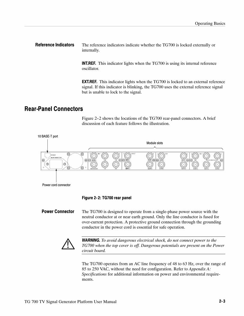
Rear-Panel ConnectorsFigure 2--2 shows the locations of the TG700 rear-panel connectors. A briefdiscussion of each feature follows the illustration.
Power cord connector
10 BASE-T port
Module slots
Figure 2- 2: TG700 rear panel
The TG700 is designed to operate from a single-phase power source with theneutral conductor at or near earth ground. Only the line conductor is fused forover-current protection. A protective ground connection through the groundingconductor in the power cord is essential for safe operation.
WARNING. To avoid dangerous electrical shock, do not connect power to theTG700 when the top cover is off. Dangerous potentials are present on the Powercircuit board.
The TG700 operates from an AC line frequency of 48 to 63 Hz, over the range of85 to 250 VAC, without the need for configuration. Refer to Appendix A:Specifications for additional information on power and environmental require-ments.
Reference Indicators
Power Connector

Operating Basics
2- 4 TG 700 TV Signal Generator Platform User Manual
Use this port to connect to your local Ethernet network. You can control theTG700 and all installed modules remotely through the port. Also, you canupload and download various files such as signal files, logo files, and preset filesthrough the port.
Use these slots to install the modules. You can install up to four modules. Referto Appendix B : Module Installation for installation procedures for the modules.
About the Frame Reset SignalsThe TG700 uses the following three frame reset signals to output different videoformats simultaneously:
H Frame reset signal 1 (FRAME RESET 1)
This frame reset signal supports the 1/1.001 system signal, and is used by thefollowing video formats:
NTSC 1080 23.98sF525-270 1080 29.97p525-143 1080 59.94i1035 59.94i 720 59.94p1080 23.98p
These signals are synchronized with each other.
H Frame reset signal 2 (FRAME RESET 2)
This frame reset signal supports the integer system signal, and is used by thefollowing video formats:
PAL 1080 30p625-270 1080 50i1035 60i 1080 60i1080 25p 720 60p
These signals are synchronized with each other.
H Frame reset signal 3 (FRAME RESET 3)
When any of the above signal uses the frame reset signal 2, the followingvideo formats use the frame reset signal 3:
1080 24p1080 24sF
10 BASE-T Port
Module Slots

Operating Basics
TG 700 TV Signal Generator Platform User Manual 2- 5
The frequency of frame reset signal 3 is always an integral multiple of that offrame reset signal 2. Frame reset signal 3 is synchronized with frame reset signal2. Frame reset signal 1 is not synchronized with frame reset signals 2 or 3.
You can see which of the three frame reset signals are used by each output ofeach module by using the FRAME RESET STATUS submenu. Refer to FRAMERESET STATUS Submenu on page 3--6 for detailed information.
Note for Format SettingsThe TG700 displays messages to ask whether you want to disable the clockcurrently used if there is a conflict of signal format settings between two (ormore) outputs for the clock assignment.
These messages are displayed under the following conditions:
H For the DVG7 Option BK, when you output 525-143 format signals and525-270 (or 625-270) format signals simultaneously.
For example, if you set the signal format for the BLACK outputs to 525-270when the signal format for the SIGNAL outputs are set to 525-143, thefollowing message appears:
* DVG7 Clock Select, Disable 270 MHz? ** Yes : ENTER / No : CANCEL *
This message asks if you want to disable the 270 MHz clock currently inuse.
In this case, press the CANCEL button to cancel the new format setting orpress the ENTER button to enable the setting and then re-set the signalformat for the other outputs.
H For the HDVG7 Option BK, when you output serial digital signals and serialdigital black signals using the 74.25 MHz clock and 74.25/1.001 MHz clocksimultaneously; or for the combination of the AGL7, AWVG7, BG7, andHDVG7, when you output serial digital signals and a HDTV trilevel syncsignal, or HDTV trilevel sync signals using the 74.25 MHz clock and74.25/1.001 MHz clock simultaneously.
For example, if you set the HDTV trilevel sync signal format for theBLACK 4 output of the BG7 to 1080 59.94i when the HDTV trilevel syncsignal format for the BLACK 3 output of the AGL7 is set to 1080 50i, thefollowing message appears:

Operating Basics
2- 6 TG 700 TV Signal Generator Platform User Manual
* HD Clock Select, Disable 74.25 MHz? ** Yes : ENTER / No : CANCEL *
This message asks if you want to disable the 74.25 MHz clock currently inuse.
In this case, press the CANCEL button to cancel the new format setting, orpress the ENTER button to enable the setting and then reset the signalformat for the other outputs.

Reference


TG 700 TV Signal Generator Platform User Manual 3- 1
Using the Menu Control Buttons and Menu Displays
This section describes how to control all of the instrument functions using thefront-panel control buttons and menus.
Mainframe Main MenuWhen you power on the TG700 and the initializing process for all of the installedmodule is completed, the top menu item of the mainframe main menu appears onthe LCD display. Press the up (Y) or down (B) arrow button to scroll throughthe available menu selections in the main menu.
The mainframe main menu allows you to access submenus to set the varioussystem settings. Figure 3--1 shows the mainframe main menu.
TG700 : PRESET
TG700 : SEQUENCE
TG700 : FRAME RESET STATUS To FRAME RESET STATUS Submenu(page 3--6)
ENTER
CANCEL
TG700 : UTILITY To UTILITY Submenu(page 3--7)
ENTER
CANCEL
To SEQUENCE Submenu(page 3--4)
ENTER
CANCEL
To PRESET Submenu(page 3--2)
ENTER
CANCEL
Power on the TG700 mainframe
Figure 3- 1: Mainframe main menu

Using the Menu Control Buttons and Menu Displays
3- 2 TG 700 TV Signal Generator Platform User Manual
PRESET. Recalls instrument settings saved as a preset, or saves the currentinstrument settings as a preset. When you select this menu item and then pressthe ENTER button, you access the PRESET submenu. Refer to PRESETSubmenu on this page for detailed information.
SEQUENCE. Selects and executes a sequence program loaded into the TG700.Select this menu item and press the ENTER button, to access the SEQUENCEsubmenu. Refer to SEQUENCE Submenu on page 3--4 for detailed information.
FRAME RESET STATUS. Displays the status of the frame reset signals. Select thismenu item and press the ENTER button to access the FRAME RESET STATUSsubmenu. Refer to FRAME RESET STATUS Submenu on page 3--6 for detailedinformation.
Also, refer to About the Frame Reset Signals on page 2--4 for detailed informa-tion about the frame reset signals.
UTILITY. Sets the system related settings such as network parameters and signalsets assignment to the front-panel test signal buttons. Select this menu item andpress the ENTER button, to access the UTILITY submenu. Refer to UTILITYSubmenu on page 3--7 for detailed information.
This menu allows you to recall instrument settings saved as a preset or save thecurrent instrument settings to a preset. Use the up (Y) or down (B) arrow buttonto scroll through the menu items. Figure 3--2 shows the PRESET submenu.
The following three presets are named at the factory and can be used for yourown application:
H Power On Default: When you save instrument settings in the preset, theinstrument settings can be loaded into the TG700 automatically at power on.If one of the seven presets is selected in the GPI (General Purpose Interface),the preset takes precedence over the Power On Default. You cannot assignthe preset name with the other preset.
NOTE. If you want to save network parameters to a preset, use the Power OnDefault preset.
H User Default: The preset for saving the user specified default settings. If yousave new instrument settings in this preset, a confirmation message appearsto prevent overwriting.
PRESET Submenu

Using the Menu Control Buttons and Menu Displays
TG 700 TV Signal Generator Platform User Manual 3- 3
H Factory Default: In this preset, the factory default settings are saved. Usethis preset to reset the mainframe and all of the installed modules to thefactory default settings. The following settings are not affected by the factorydefault: LCD contrast, front panel timeout, and network parameters.
TG700 : PRESET : RECALLPower On Default Select a preset to recall
Select PRESET in the main menu
TG700 : PRESET : SAVEPower On Default Select a preset number to save instrument settings
TG700 : PRESET : RENAMEPRESET 1
Select a preset torename
Edit the preset name
ENTER
CANCEL
TG700 : PRESET : DELETEPRESET 1 Select a preset to delete
Figure 3- 2: PRESET submenu
RECALL. Recalls instrument settings saved as a preset. Use the left (A) or right(") arrow button to select a different preset, and then press the ENTER button toimplement the selection.
While the preset is loading into the instrument, the message “Now Loading ...”appears on the display. When the loading is complete, the message “Done (PressCANCEL)” appears. Press the CANCEL button.
SAVE. Saves the current instrument settings to one of the fourteen presets. Usethe left (A) or right (") arrow button to select the the destination preset, andthen press the ENTER button to implement the selection.

Using the Menu Control Buttons and Menu Displays
3- 4 TG 700 TV Signal Generator Platform User Manual
RENAME. Renames the specified preset name. Perform the following steps torename a preset name:
1. Use the left (A) or right (") arrow button to select the preset you want torename.
2. Press the ENTER button twice to begin editing the preset name. Theunderscore character ( _ ) appears under the first letter of the preset name.
3. Use the left (A) or right (") arrow button to move the underscore characterto the letter you want to modify.
4. Use the up (Y) or down (B) arrow button to select the new character.
The available characters include the full alphabet, numerals from 0 to 9, andmany standard ASCII symbols. The text strings may contain up to 32characters.
5. Enter all of the desired characters then press ENTER button.
6. Press the CANCEL button twice to exit the PRESET submenu. This returnsto the top of the mainframe main menu.
7. Press the ENTER button to reenter the PRESET submenu.
8. Use the up (Y) or down (B) arrow button to select the SAVE menu item.
9. Use the left (A) or right (") arrow button to select the preset name edited instep 4.
10. Press ENTER button to save the preset with the new name.
DELETE. Deletes the specified preset. Use the left (A) or right (") arrow buttonto select the preset you want to delete, and then press the ENTER button toimplement the selection. You cannot delete the following presets: Power onDefault, User Default, and Factory Default.
This menu allows you to select and run a sequence that is already loaded into theTG700. A sequence is a series of generator settings defined using the Tcllanguage and SCPI commands. The TG700 loads a sequence and runs thecommand and settings in the order dictated by the sequences file. Figure 3--3shows the SEQUENCE submenu.
SEQUENCE Submenu

Using the Menu Control Buttons and Menu Displays
TG 700 TV Signal Generator Platform User Manual 3- 5
TG700 : SEQUENCE : PLAYBACKNo Sequence Loaded Select a sequence to be run
TG700 : SEQUENCE : STOP
Select SEQUENCE in the main menu
ENTERStop the sequence currently running
Figure 3- 3: SEQUENCE submenu
PLAYBACK. Selects and runs a sequence. Use the left (A) or right (") arrowbutton to select the sequence you want to run, and then press the ENTER buttonto run the sequence.
If no sequence is loaded into the instrument, the message “No Sequence Found”is displayed on the second line.
STOP. Stops the sequence currently running. When you select the menu item andthen press the ENTER button, the sequence is stopped.
Refer to Sequence Programming on page 3--103 for detailed information aboutthe sequence.

Using the Menu Control Buttons and Menu Displays
3- 6 TG 700 TV Signal Generator Platform User Manual
This menu allows you to display which of the three frame reset signals is used bythe output of the installed modules. Use the up (Y) or down (B) arrow button toscroll through the menu items. Figure 3--4 shows the FRAME RESET STATUSsubmenu.
TG700 : FR STATUS : FRAME RESET 114.985 Hz : AGL7[1] : B1, B2 Select a module to be displayed
Select FRAME RESET STATUSin the main menu
TG700 : FR STATUS : FRAME RESET 23.000 Hz : BGL7[2] : B3 Select a module to be displayed
TG700 : FR STATUS : FRAME RESET 31.250 Hz : BG7[2] : B1 Select a module to be displayed
Figure 3- 4: FRAME RESET STATUS submenu
FRAME RESET 1. Display the module(s) and output(s) using the frame resetsignal 1. If two or more modules use the frame reset signal, use the left (A) orright (") arrow button to change the modules to be displayed.
FRAME RESET 2. Display the module(s) and output(s) using the frame resetsignal 2. If two or more modules use the frame reset signal, use the left (A) orright (") arrow button to change the modules to be displayed.
FRAME RESET 3. Display the module(s) and output(s) using the frame resetsignal 3. If two or more modules use the frame reset signal, use the left (A) orright (") arrow button to change the modules to be displayed.
The character after the module name represents the output connector of themodule. For example, B1 represents BLACK 1 connector.
FRAME RESET STATUSSubmenu

Using the Menu Control Buttons and Menu Displays
TG 700 TV Signal Generator Platform User Manual 3- 7
This menu allows you to set the system related settings such as the contrast ofthe LCD display and the network parameters. Use the up (Y) or down (B) arrowbutton to scroll through the menu items. Figure 3--5 shows the UTILITYsubmenu.
TG700 : UTILITY : VERSION INFO (H/W)CPU [0] V2.0
TG700 : UTILITY : LCD CONTRASTLOW << 17 >> HIGH
Select the module for which the hardwareversion information will be displayed
Adjust the display contrast
Select UTILITY in the main menu
TG700 : UTILITY : VERSION INFO (F/W)CPU [0] Ver. 4.3
Select the module for which the firmwareversion information will be displayed
TG700 : UTILITY : NETWORKInformation
InformationSetup
TG700 : UTILITY : SIGNAL KEY ASSIGN To SIGNAL KEY ASSIGN Submenu
ENTER
CANCEL
TG700 : UTILITY : DIAGNOSTICS To DIAGNOSTICS Submenu
ENTER
CANCEL
To NETWORK INFORMATION Submenu orTo NETWORK SETUP Submenu
ENTER
CANCEL
TG700 : UTILITY : FRONT PANEL DISABLETime Out : OFF
OFF 10 Minutes1 Minute 30 Minutes5 Minutes 1 Hour
Figure 3- 5: UTILITY submenu
VERSION INFO (H/W). Displays the hardware version of the mainframe and themodules currently installed. Use the left (A) or right (") arrow button to selectthe module you want to display the information.
UTILITY Submenu

Using the Menu Control Buttons and Menu Displays
3- 8 TG 700 TV Signal Generator Platform User Manual
VERSION INFO (F/W). Displays the firmware version number for the mainframeand the modules currently installed. Use the left (A) or right (") arrow button toselect the module you want to display the information.
SIGNAL KEY ASSIGN. Assigns signal sets to the front-panel test signal buttons,and assigns a frame picture file created by the Frame picture Generator applica-tion supplied with the TG700 to the OTHER test signal button (Option FP only).When you select this menu item and press the ENTER button, you will accessthe SIGNAL KEY ASSIGN submenu. Refer to SIGNAL KEY ASSIGN Submenuon page 3--9 for detailed information.
LCD CONTRAST. Adjusts the contrast of the LCD display. You can lower thecontrast by pressing the left (A) arrow button and raise the contrast by pressingthe right (") arrow button.
FRONT PANEL DISABLE. Sets the timeout period until the front-panel buttons aredisabled. Use the left (A) or right (") arrow button to make the selection. Thechoices are OFF, 1 Minute, 5 Minutes, 10 Minutes, 30 Minutes, and 1 Hour.Press the ENTER button to enable the selection.
When you select any of these timeout periods (except OFF), the front-panelbuttons are disabled when that time passes without a button push. When thishappens, press and hold the FRONT PANEL ENABLE button for about 1second to restart the timeout counter and enable the front-panel buttons
The indicator next to the FRONT PANEL ENABLE button lights when thefront-panel buttons are enabled.
NETWORK. Displays the network parameters currently set or sets the networkparameters for the 10BASE-T port on the TG700. Use the left (A) or right (")arrow button to toggle between Information and Setup. When you selectInformation and press the ENTER button, you will access the NETWORKINFORMATION submenu. When you select Setup and press the ENTER button,you will access the NETWORK SETUP submenu.
Refer to NETWORK INFORMATION Submenu on page 3--10 for detailedinformation about the submenu. Also, refer to NETWORK SETUP Submenu onpage 3--11 for detailed information about the submenu.
DIAGNOSTICS. Executes the diagnostic routines for the mainframe and installedmodules. When you select the menu item and then press the ENTER button, youaccess the DIAGNOSTICS submenu. Refer to DIAGNOSTICS Submenu on page3--13 for detailed information.

Using the Menu Control Buttons and Menu Displays
TG 700 TV Signal Generator Platform User Manual 3- 9
This menu allows you to assign signal sets to a specific test signal button on thefront panel. You can also assign a frame picture file created by the Frame PictureGenerator application supplied with the TG700 to the OTHER test signal button.Figure 3--6 shows the SIGNAL KEY ASSIGN submenu.
TG700 : TEST SIGNAL KEY ASSIGNHDVG7 Select a module
Select SIGNAL KEY ASSIGNin the UTILITY submenu
TG700 : FRAME PICTURE KEY ASSIGNHDVG7 Select a module
Figure 3- 6: SIGNAL KEY ASSIGN submenu
TEST SIGNAL KEY ASSIGN. Assigns signal sets to a specific test signal button onthe front panel.
For each test signal button, the signal sets corresponding to the button name arealready assigned at the factory. For example, when you press the COLOR BARtest signal button, the three types of color bars signal (100% Color Bars, 75%Color Bars, and SMPTE Color Bars) are output.
Perform the following steps to assign signal sets to a specific test signal button.
1. Use the left (A) or right (") arrow button to select the module you want toassign signal sets to, and then press the ENTER button. This will display thefollowing submenu to assign signal sets.
TG700 : HDVG7 : COLOR BAR KEYCOLOR BAR
The first line shows the test signal button name, and second line shows thesignal set name.
2. Use the up (Y) or down (B) arrow button to select the test signal button (forexample COLOR BAR KEY) to be assign signal sets.
3. Use the left (A) or right (") arrow button to select the signal sets (forexample COLOR BAR) you want to assign.
4. Press the ENTER button to implement the assignment.
SIGNAL KEY ASSIGNSubmenu

Using the Menu Control Buttons and Menu Displays
3- 10 TG 700 TV Signal Generator Platform User Manual
5. Repeat Steps 2 to 4 until all signal set assignments are completed.
FRAME PICTURE KEY ASSIGN. Assigns frame picture files downloaded to theTG700 to the OTHER test signal button. This operation is required to output theframe picture files as a picture (natural picture or test pattern).
NOTE. When you download a frame picture file created by the Frame PictureGenerator application and output it a picture, Option FP must be installed.
Perform the following steps to assign a frame picture file to the OTHER testsignal button:
1. Use the left (A) or right (") arrow button to select the module you want toassign a frame picture file, and press the ENTER button. This will displaythe following submenu.
TG700 : HDVG7 : OTHER KEY1080 60i
The second line shows the folder name created when the frame picture filewas downloaded to the TG700.
2. Use the left (A) or right (") arrow button to select the folder in which theframe picture file is saved.
3. Press the ENTER button to implement the assignment.
Refer to Using Frame Picture Generator on page 3--39 for detailed informationabout how to create a frame picture file. Also, refer to Using TG7 Comm for FileTransfers on page 3--27 for detailed information about how to download a framepicture file from the PC to the TG700.
This menu allows you to display all of the network parameters currently set.Figure 3--7 shows NETWORK INFORMATION submenu.
TG700 : UTILITY : NETWORK : INFOIP Address : 172.17.37.59
IP AddressSubnet MaskBroadcast AddressGateway AddressMAC AddressDHCP Address
Select Information in theUTILITY : NETWORKmenu
Figure 3- 7: NETWORK INFORMATION submenu
NETWORK INFORMATIONSubmenu

Using the Menu Control Buttons and Menu Displays
TG 700 TV Signal Generator Platform User Manual 3- 11
Use the left (A) or right (") arrow button to select the menu items and displaythe address value. The following selections are available: IP Address, SubnetMask, Broadcast Address, Gateway Address,MAC Address, and DHCPServer.
This menu allows you to set network parameters for the 10 BASE-T port on theTG700. These parameters will be used when you connect the TG700 to a remotecomputer (PC) so that you can control the TG700 remotely using the PC andtransfer various files between the TG700 and the PC. Use the up (Y) or down(B) arrow button to scroll through the menu items. Figure 3--8 shows theNETWORK SETUP submenu.
TG700 : UTIL : NET SETUP : DHCPEnable
TG700 : UTIL : NET SETUP : IP ADDRESS000.000.000.000
TG700 : UTIL : NET SETUP : SUBNET MASK000.000.000.000
TG700 : UTIL : NET SETUP : GATEWAY ADDR000.000.000.000
EnableDisable
Set the IP address
Set the subnet address
Set the gateway address
TG700 : UTIL : NET SETUP : BRDCAST ADDR000.000.000.000 Set the broadcast address
Select Setup in theUTILITY : NETWORKmenu
Figure 3- 8: NETWORK SETUP submenu
DHCP. Selects valid or invalid IP address settings by DHCP (Dynamic HostConfiguration Protocol). Use the left (A) or right (") arrow button to selectbetween Enable and Disable. Press the ENTER button to implement theselection. If you select Disable in this menu, you will need to set address valuesin each of the menu items described below.
NETWORK SETUPSubmenu

Using the Menu Control Buttons and Menu Displays
3- 12 TG 700 TV Signal Generator Platform User Manual
Refer to the user documentation supplied with your server OS for detailedinformation about DHCP server functions.
NOTE. Under some network environments, the TG700 may not be able to get theIP address automatically from a DHCP server. In this case, you need to enter theappropriate address value in each submenu item.
IP ADDRESS. Sets the IP address of the TG700. Press the ENTER button to enterthe edit mode to input the address. Then use the left (A) or right (") arrowbutton to move the underscore character ( _ ), and use the up (Y) or down (B)arrow button to enter the value. After you enter the value, press the ENTERbutton to enable the value. When no value is set, the default value is used. If theDHCP menu item is set to Enable, the IP address automatically obtained fromthe DHCP server is used.
NOTE. If you enter blank characters for the IP address, the network function ofthe TG700 becomes invalid.
SUBNET MASK. Sets the subnet address of the TG700. Press the ENTER buttonto enter the edit mode to input the address. Then use the left (A) or right (")arrow button to move the underscore character ( _ ), and use the up (Y) or down(B) arrow button to enter the value. After you enter the value, press the ENTERbutton to enable the value. When no value is set, the default value is used. If theDHCP menu item is set to Enable, the subnet address automatically obtainedfrom the DHCP server is used.
BRDCAST ADDR. Sets the broadcast address of the TG700. Press the ENTERbutton at first to enter the edit mode to input the address. Then use the left (A) orright (") arrow button to move the underscore character ( _ ), and use the up (Y)or down (B) arrow button to enter the value. After you enter the value, press theENTER button to enable the value. If the DHCP menu item is set to Enable, thebroadcast address automatically obtained from the DHCP server is used.
GATEWAY ADDR. Sets the gateway address of the TG700. Press the ENTERbutton to enter the edit mode to input the address. Then use the left (A) or right(") arrow button to move the underscore character ( _ ), and use the up (Y) ordown (B) arrow button to enter the value. After you enter the value, press theENTER button to enable the values.
Refer to Connecting to a Network on page 3--15 for detailed information aboutconnecting the TG700 to a PC.

Using the Menu Control Buttons and Menu Displays
TG 700 TV Signal Generator Platform User Manual 3- 13
This menu allows you to execute the diagnostic routines for the mainframe andinstalled modules. Figure 3--9 shows the DIAGNOSTICS submenu.
TG700 : UTILITY : DIAGNOSTICSPress ENTER to Proceed
Select DIAGNOSTICSin the UTILITY submenu
Execute the diagnostic routinesENTER
Figure 3- 9: DIAGNOSTICS submenu
CAUTION. When you execute the diagnostic routines, be sure to save the currentinstrument settings to a preset. After the diagnostics is completed, reboot theinstrument and then recall the saved settings.
Press the ENTER button to execute the diagnostic routines. If all of thediagnostic routines are completed without any errors, the instrument will display“Pass”.
If a diagnostic error is displayed, contact your local Tektronix Field Office orrepresentative.
NOTE. The front-panel buttons are disabled until the diagnostic routines arecompleted.
DIAGNOSTICS Submenu

Using the Menu Control Buttons and Menu Displays
3- 14 TG 700 TV Signal Generator Platform User Manual

TG 700 TV Signal Generator Platform User Manual 3- 15
Connecting to a Network
The TG700 has a 10 BASE-T port on the rear panel that allows you to controlthe instrument remotely, using your PC to upload and download various filessuch as signal files or logo files.
This section provides instructions for connecting the TG700 to a single PC or anetwork and setting the network parameters for the 10 BASE-T port.
Refer to Using TG7 Comm for File Transfers on page 3--27 for detailedinformation about how to upload and download files using the 10 BASE-T port.
Connecting the TG700 to your PC(s)The TG700 uses the rear-panel 10 BASE-T port (see Figure 2--2 on page 2--3) tocommunicate with a PC. Use one of the following two methods to connect theTG700 to your PC(s).
H If you are connecting the TG700 directly to a single PC, use a crossoverEthernet cable to connect between the 10 BASE-T port on the TG700 andthe Ethernet port on the PC. If you need to construct your own crossovercable, Figure 3--10 shows the pin connections to change on a straight cableto produce a crossover cable.
H If you are connecting the TG700 to your local Ethernet network, use astraight Ethernet cable to connect between the 10 BASE-T port on theTG700 and the Ethernet hub port of your local network. By connecting to anEthernet network, you can access the TG700 using any PC on the network.
Pin 1 TDPin 2 TDPin 3 RDPin 6 RD
Pin 1 TDPin 2 TDPin 3 RDPin 6 RD
Figure 3- 10: Pin connections for a 10BASE-T crossover Ethernet cable

Connecting to a Network
3- 16 TG 700 TV Signal Generator Platform User Manual
Setting Ethernet Network ParametersYou can set the network parameters for the TG700 using the NETWORKSETUP submenu.
Perform the following procedure to access the NETWORK SETUP submenu.
1. Press the front-panelMODULE button repeatedly to display the mainframemain menu.
2. Use the up (Y) or down (B) arrow button to select UTILITY and then pressthe ENTER button. This accesses the UTILITY submenu.
3. Use the up (Y) or down (B) arrow button to select Network.
4. Use the left (A) or right (") arrow button to select Setup. This accesses theNETWORK SETUP submenu shown in Figure 3--11.
TG700 : UTIL : NET SETUP : DHCPEnable
TG700 : UTIL : NET SETUP : IP ADDRESS000.000.000.000
TG700 : UTIL : NET SETUP : SUBNET MASK000.000.000.000
TG700 : UTIL : NET SETUP : GATEWAY ADDR000.000.000.000
TG700 : UTIL : NET SETUP : BRDCAST ADDR000.000.000.000
Select Setup in the UTILITY :NETWORKmenu item
EnableDisable
Set the address value
Set the address value
Set the address value
Set the address value
Figure 3- 11: NETWORK SETUP submenu
Accessing the NETWORKSETUP Submenu

Connecting to a Network
TG 700 TV Signal Generator Platform User Manual 3- 17
Perform the following procedure to set the network parameters for the TG700.The settings depend on whether a DHCP (Dynamic Host Configuration Protcol)server is in the network connected to the TG700.
When the DHCP server is in the network.
If a DHCP server is in the network, when you select Enable in the NET SETUP: DHCP menu item, the TG700 functions as a DHCP client. In this case, you canregister the addresses such as the IP address and subnet mask used by theTG700. This way, the TG700 accesses the DHCP server and gets the addressesautomatically when connected to the network.
Refer to the user documentation supplied with your server OS for detailedinformation about DHCP server functions.
NOTE. Under some network environments, the TG700 may not be able to get theIP address automatically from a DHCP server. In this case, you need to enter theappropriate address value in each submenu item.
When the DHCP server is not in the network.
When the DHCP server is not in the network, perform the following procedure toset the network parameters.
1. If you connect the TG700 directory to a single PC:
a. Set the IP ADDRESS parameter to be the same IP address as the PC’saddress except for the last number. The last number must be differentthan the last number in the PC’s IP address.
b. Set the SUBNET MASK parameter to be the same net mask (subnetmask) used by the PC. Do not enter a number if the PC does not have anet mask.
c. You do not need to enter a BRDCAST ADDR and GATEWAY ADDRif you are directly connected to a single PC.
2. If you connect the TG700 to your local Ethernet network, see the Cautionnote below.
CAUTION. To prevent communication conflicts on your Ethernet network, askyour local network administrator for the correct numbers to enter in theNETWORK PARAMETERS submenu if you connect the TG700 to your localEthernet network.
3. Verify the Ethernet connection by using a ping command from the PC.
Setting the NetworkParameters

Connecting to a Network
3- 18 TG 700 TV Signal Generator Platform User Manual
TG 700 TV Signal Generator Platform User Manual 3- 19
Using the General Purpose Interface (GPI)
The 10 BASE-T port of the TG700 can be used as the General Purpose Interface(GPI) by changing the internal jumper settings. When you enable the GPI, youcan recall one of the seven presets, output an alarm signal, and display an alarmstatus on the LCD.
This section describes how to set the GPI and its available features.
CAUTION. When you enable the GPI, do not connect the TG700 to a network.The network may be damaged.
NOTE. When you enable the GPI, you cannot perform the operation using anetwork such as sending and receiving remote commands or downloadingsignals.
After you have enabled the GPI, be sure to apply the GPI label (provided withthe instrument) to the rear panel to show that the instrument cannot connect to anetwork.
Setting the GPIThe GPI can be enabled by the jumper settings of the connectors J000, J002,J004, J006, and J008 on the A10 MAIN board.
Since the A10 MAIN board is located inside the chassis, you need to remove thetop cover to change the jumper settings.
Perform the following procedure to remove the top cover and to change thejumper settings. You need a screwdriver with a # 2 Phillips tip to remove the topcover.
CAUTION. To avoid a shock hazard, be sure to remove the power cord beforeremoving the top cover. Failure to remove the power cord can result in seriousinjury or death.
1. Disconnect the power cord from the line voltage source.
2. Use a screw driver with a #2 Phillips tip to remove the two screws securingthe front of the top cover to the instrument. See Figure 3--12.

Using the General Purpose Interface (GPI)
3- 20 TG 700 TV Signal Generator Platform User Manual
3. Slide the top cover toward the rear, and then lift it off the instrument.See Figure 3--12.
Figure 3- 12: Top cover removal
4. Locate the connectors J000, J002, J004, J006, and J008 on the A10 MAINboard. See Figure 3--13.

Using the General Purpose Interface (GPI)
TG 700 TV Signal Generator Platform User Manual 3- 21
J630 J620 J610 J600J700
Front
J000/J002/J004/J006/J008
Figure 3- 13: Location of the connectors J000/J002/J004/J006/J008
5. Move all of the jumpers from pins 1--2 to pins 3--4. Table 3--1 shows thejumper settings of the connectors and available feature.
NOTE. To enable the GPI, be sure to move all of the jumpers to pins 2--3.
Table 3- 1: Jumper settings of the connectors and available feature
Jumper illustration Jumper setting Feature
J000
J002
J004
J006
J008
3 1
All of the jumpers short pins 1--2.(factory default settings)
LAN (Ethernet)
3 1
J000
J002
J004
J006
J008
All of the jumpers short pins 2--3. GPI

Using the General Purpose Interface (GPI)
3- 22 TG 700 TV Signal Generator Platform User Manual
6. After moving the jumpers, place the top cover on the instrument and slide ittoward the front.
7. Use a screw driver with a #2 Phillips tip to install the two screws securingthe front of the top cover to the instrument.
8. Remove the protective backing from the GPI label provided with theinstrument, and then apply it to the rear panel. See Figure 3--14.
GPI Do not connect to NetworkGPI label
Figure 3- 14: Applying the GPI label to the rear panel
Pin Assignments of the 10 BASE-T ConnectorFigure 3--15 shows the pin assignments of the 10 BASE-T connector when it isused as the GPI. The pins 1, 2, and 3 are used to input signals for recalling apreset. The pin 4 is used to output an alarm signal. Frame ground is used for theground return. When using a shielded LAN cable (shielded twisted pair cable),you can utilizes the shield of the cable as ground.
1 2 3 6
Pin number Function Level
Input
Input
Input
Output
1
2
3
6
High> 1.4 V or open (connected to an internal 10 kΩ pull-up resistor)
Low< 0.4 V or ground (input impedance: 10 kΩ)
Low< 0.4 V or ground (when drawn 100 mA; maximum on-resistor 4Ω)
10 BASE-T connector
Figure 3- 15: Pin assignments of the 10 BASE-T connector for the GPI

Using the General Purpose Interface (GPI)
TG 700 TV Signal Generator Platform User Manual 3- 23
Recalling a PresetWhen you enable the GPI, you can recall one of the seven presets by combina-tions of signal levels for pins 1, 2, and 3 of the 10 BASE-T connector. Table 3--2shows the combinations of signal levels for the pins and the preset number to berecalled.
Table 3- 2: Combinations of signal levels and the corresponding preset
Pin 1 Pin 2 Pin 3 Preset number
High High Low 1
HIgh Low High 2
High Low Low 3
Low High High 4
Low High Low 5
Low Low High 6
Low Low Low 7
All of the input signals are active low; when the signal level(s) for the specifiedpin(s) goes from High to Low, the corresponding preset is recalled. For example,when the signal level for pin 3 goes from High to Low, the preset 1 is recalled.
NOTE. Since the signal transition cannot be detected on the edge of the signal,the signal level needs to hold. It requires about 0.5 seconds to recall a preset,and then the settings of the TG700 change. The required time to change thesettings depends on the contents of a preset.

Using the General Purpose Interface (GPI)
3- 24 TG 700 TV Signal Generator Platform User Manual
Outputing an Alarm SignalWhen you enable the GPI, the TG700 can output an alarm signal from pin 6 onthe 10 BASE-T connector when one of the following internal errors occur:
H When the fan stops working.
H When a genlock signal is not connected.
H When the TG700 does not lock to a genlock signal.
H When the frequency of the genlock signal and the internal reference shiftconsiderably, and the TG700 seems to be near loss of lock.
The output signal is active low; the signal level for pin 6 goes from High to Lowwhen any errors occur.
The alarm signal output can be enabled using the GPI ALARM OUTPUT menuitem in the UTILITY submenu. Refer to GPI ALARM OUTPUT on page 3--25for more information.
When the GPI is enabled, the ALARM menu items are displayed instead of theUTILITY menu item. The ALARM menu allows you to enable or disable thealarm signal output, to reset the alarm signal output, and to display the alarmstatus. Figure 3--16 shows the ALARM menu.
TG700 : UTILITY : FRONT PANEL DISABLETime Out : Off
TG700 : UTILITY : ALARM STATUSNo Alarm
TG700 : UTILITY : ALARM RESETPress ENTER to Clear Alarm
TG700 : UTILITY : DIAGNOSTICS
EnableDisable
TG700 : UTILITY : GPI ALARM OUTPUTDisable
Alarm menu
Figure 3- 16: ALARM menu
ALARM Menu

Using the General Purpose Interface (GPI)
TG 700 TV Signal Generator Platform User Manual 3- 25
ALARM STATUS. Displays the alarm status detected inside the instrument. Thepossible messages for the status are as follows:
H No Alarm: No errors have been detected.
H Genlock : Near Loss of Lock: The frequency of the genlock signal and theinternal reference signal shift considerably, and the TG700 seems to be nearloss of lock. If this happens it is recommended that you check the frequencyof the genlock signal or internal reference signal of the TG700.
H Genlock : Loss of Lock: The TG700 does not lock to a genlock signal.
H Genlock : No Signal: A genlock signal is not connected.
H Fan Fault: The fan on the rear panel stops working.
NOTE. In the alarm status display, the instrument displays an error message thathas been detected in the past. In order to display the latest message, you need toaccess the other menu item (press the CANCEL button) and to return to theALARM STATUS menu again.
ALARM RESET. Resets the alarm status. The TG700 holds the alarm status evenif the cause of the alarm is eliminated. Use this menu item when you need toreset the status. If the cause of the error is not eliminated, the alarm status is setagain when you reset the status.
GPI ALARM OUTPUT. Enables or disables the alarm signal output. Use the left(A) or right (") arrow button to select between Enable and Disable. ForEnable, an alarm signal is output from pin 6 of the 10 BASE-T connector whenany error is detected inside the instrument. For Disable, the alarm signal outputis disabled.
Press the ENTER button to confirm the selection.

Using the General Purpose Interface (GPI)
3- 26 TG 700 TV Signal Generator Platform User Manual

TG 700 TV Signal Generator Platform User Manual 3- 27
Using TG7 Comm for File Transfers
TG7 Comm, a standard accessory with the TG700, is a software application for aPC using the Microsoft Windows system. TG7 Comm provides the capability totransfer signal, logo, preset, frame picture, or sequence files between a PC andthe TG700 using the Ethernet interface.
This section provides the following information:
H PC system requirements
H Installation instruction and Ethernet setup
H Starting and exiting TG7 Comm
H Elements of TG7 Comm window
H Using the TG7 Comm menus
H TG7 Comm tutorials
PC System RequirementsYour PC requires the following minimum system requirements to load andoperate the TG7 Comm application:
H Microsoft Windows 95, 98, 2000, or NT4.0 (for Windows 95 or NT 4.0,Internet Explorer 4.01 or later needs to be installed)
H Ethernet interface
Installation Instructions and Ethernet SetupThis subsection provides the following instructions: installing the TG7 Commapplication on your PC, creating a desktop shortcut icon on the PC to run TG7Comm, connecting your PC(s) to the TG700 using the Ethernet port, and settingthe required Ethernet parameters.
The following installation instructions assume that you are familiar with thebasics of using the Windows operating system. If necessary, read your Windowsuser documentation before installing TG7 Comm.
Installing TG7 Comm

Using TG7 Comm for File Transfers
3- 28 TG 700 TV Signal Generator Platform User Manual
Perform the following procedure to install TG7 Comm:
1. Be sure that your PC meets the requirements listed under PC SystemRequirements above before proceeding with the installation.
2. Insert the TG700 Signal Generator Platform Software Library CD-ROM intoa CD-ROM drive on your PC.
3. Double-click theMy computer icon and the CD-ROM drive icon on thePC desktop. The PC will display the contents of the TG700 Signal GeneratorPlatform Software Library CD-ROM.
4. Double-click the Tools folder and the TG7 Comm folder on the PC desktop.The PC will display the contents of the TG7 Comm folder.
5. Double-click the Setup.exe icon in the folder.
This copies initial files of the TG7 Comm application. For a while, theWelcome window appears on the PC desktop.
6. Read the displayed information, and then click the Next> button to proceedwith the installation.
The PC will display the Choose Destination Location window. The defaultdirectory location for the application is displayed. If you want to install TG7Comm in a custom location, click the Browse... button, and then select orcreate a custom directory location.
7. Click the Next> button to proceed.
The PC will display the Select Program Folder window. The default namefor the program folder is displayed. If you want to change the name, type ina new name or select a name from the Existing Folders list.
8. Click the Next> button to proceed. The PC will display the Start CopyingFiles window.
9. Click the Next> button to start the installation.
If the installation is successful, the Setup Complete windows is displayed.
Perform the following procedure to create an icon on your PC desktop that youcan use to run the TG7 Comm application.
1. On your PC display, move the mouse cursor to any unoccupied desktop area,and then click the right mouse button to open the desktop menu.
2. From the desktop menu select New, and then select Shortcut to open theCreate Shortcut dialog box.
3. Click the Browse... button in the Create Shortcut dialog box.
Creating a DesktopShortcut Icon

Using TG7 Comm for File Transfers
TG 700 TV Signal Generator Platform User Manual 3- 29
4. Use the Browse dialog box to locate the TG7 Comm directory.
a. If you installed the TG7 Comm application using the default directorylocation and the default folder name in the installation procedure, selectthe following directory folders in order: Program Files, Tektronix,TG700, and TG7 Comm.
b. If you installed the TG7 Comm application to a custom location or gavethe application folder a custom name, you will need to select yourcustom directory path.
c. You should now be at a location in the PC directory structure where thebrowse list box shows the tg7comm.exe file.
5. Select the tg7comm.exe file (tg7comm.exe will be displayed in the file namebox), and then click the Open button. The directory path to the tg7comm.exefile will now be displayed in the Command Line box of the Create Shortcutdialog box.
6. Click the Next> button in the Create Shortcut dialog box. The default nameof the shortcut icon is now displayed in the dialog box. You can edit the iconname to suit your needs or accept the default name.
7. Click the Finish button to finish creating the desktop shortcut icon. Thetg7comm.exe shortcut icon will now appear on the PC desktop. You can startthe TG7 Comm application by double-clicking the tg7comm.exe (or yourcustom name) shortcut icon.
TG7 Comm uses the rear-panel 10 BASE-T port on the TG700 to communicatewith a PC.
Refer to Connecting to a Network on page 3--15 for detailed information abouthow to connect your PC(s) to the TG700.
Connecting Your PC(s) tothe TG700

Using TG7 Comm for File Transfers
3- 30 TG 700 TV Signal Generator Platform User Manual
Before you can use TG7 Comm to transfer files between the TG700 and yourPC(s), you must set the Ethernet network parameters for both the TG700 and theTG7 Comm application.
NOTE. Use the ping command from the PC to verify network communicationsafter you set the Ethernet network parameters for the TG700 and for the TG7Comm application.
Ethernet Parameters for the TG700. The Ethernet network parameters for theTG700 can be set using the NETWORK SETUP submenu in the UTILITYmain menu. Refer to Setting Ethernet Network Parameters on page 3--16 fordetailed information about how to set the network parameters.
Ethernet Parameters for TG7 Comm. Perform the following procedure to set theEthernet network parameters for the TG7 Comm application:
1. Select Network from the Utility menu of the TG7 Comm application. Thiswill open the Ethernet dialog box shown in Figure 3--17.
2. Use the IP Address field in the dialog box to enter the IP address that youassigned to the TG700.
3. Click the OK button to accept the settings and close the dialog box.
Figure 3- 17: Ethernet dialog box for TG7 Comm
Setting Ethernet NetworkParameters

Using TG7 Comm for File Transfers
TG 700 TV Signal Generator Platform User Manual 3- 31
Starting and Exiting TG7 CommWhen you complete the installation procedure, you can use any of the followingmethods to start the TG7 Comm application:
H Double-click the tg7comm.exe shortcut icon on the PC desktop that youcreated during the installation procedure.
H Double-click the tg7comm.exe file name in the Program Manager window.
H Select tg7comm from the Start -- Programs menu.
To exit (quit) the TG7 Comm application, select Exit from the File menucommand list of the application.
Elements of the TG7 Comm WindowFigure 3--18 shows the TG7 Comm application window. Table 3--3 provides adescription of the elements in the application window.
Title barMenu barToolbar
Status bar
Tree view
List view
Figure 3- 18: TG7 Comm application window

Using TG7 Comm for File Transfers
3- 32 TG 700 TV Signal Generator Platform User Manual
Table 3- 3: Elements of the TG7 Comm window
Element Description
Title bar The Title bar displays the name of the application and contains thestandard window-sizing boxes for Windows.
Menu bar The Menu bar displays the names of the four pull-down menus. Refer toUsing TG7 Comm Menus on page 3--33 for detailed information about thefunctions available in the menus.
Toolbar The Toolbar provides shortcut buttons for many of the most often usedmenu commands. Click a toolbar button to select the correspondingcommand. You can toggle the toolbar display on and off using the Toolbarcommand in the View pull-down menu. Table 3--4 describes the function ofeach toolbar button.
Tree view The Tree view displays the file structure in the TG700. The contents of theselected directory is displayed in the List view. The IP address of theselected TG700 is displayed at the top of the Tree.
List view The List view displays the contents of the selected directory in the Treeview. You can use the View pull-down menu to alter the display in the Listview.
Status bar The Status bar displays the number of files (objects) stored in the selecteddirectory, the total file size of the selected directory, and the amount offree disk space in the TG700’s system memory.
Table 3- 4: Toolbar button descriptions
Icon Name Function
PC to TG Equivalent to the PC to TG command in the File menu.
TG to PC Equivalent to the TG to PC command in the File menu.
Up One Level Moves from the current folder to the upper level folder.
Large Icons Equivalent to the Large Icons command in the View menu.
Small Icons Equivalent to the Small Icons command in the View menu.
List Equivalent to the List command in the View menu.
Details Equivalent to the Details command in the View menu.

Using TG7 Comm for File Transfers
TG 700 TV Signal Generator Platform User Manual 3- 33
Using the TG7 Comm MenusThe Menu bar displays the names of the four pull-down menus: File, View,Utility, and Help. This section describes the function of each selection in thesemenus.
The File menu contains commands for managing file operations and for exitingthe TG7 Comm application. Table 3--5 describes each of the File menu com-mands.
Table 3- 5: TG7 Comm File menu commands
Command Function
PC to TG Displays the PC to TG Download dialog box where you can select the fileyou want to transfer from your PC to the directory in the TG700 selectedin the Tree view.
TG to PC When you select this command after you highlight a file in the List view ofthe TG7 Comm application, the TG to PC Upload dialog box appearswhere you can select a destination path and file name for the file you wantto transfer to your PC.
New Creates a new folder in the currently selected directory of the TG700.
Delete Deletes the file or empty folder currently selected in the TG700.
Rename Renames the file name or folder name currently selected in the TG700.
Exit Exits the TG7 Comm application.
File Menu

Using TG7 Comm for File Transfers
3- 34 TG 700 TV Signal Generator Platform User Manual
The View menu contains commands that control the appearance of theTG7 Comm application window. Table 3--6 describes each of the View menucommands.
Table 3- 6: TG7 Comm View menu commands
Command Function
Toolbar Toggles the display of the Toolbar on and off in the applicationwindow. A check mark precedes the command in the menu when theToolbar is selected for display.
Status Bar Toggles the display of the Status bar on and off in the applicationwindow. A check mark precedes the command in the menu when theStatus bar is selected for display.
Large Icons Causes the application to display files or folders in the List view usinglarge icons. A check mark precedes the command in the menu whenLarge Icons is selected.
Small Icons Causes the application to display files or folders in the List view usingsmall icons. A check mark precedes the command in the menu whenSmall Icons is selected.
List Causes the application to display files or folders in the List view in avertical list form. A check mark precedes the command in the menuwhen List is selected.
Details Causes the application to display files or folders in the List view in adetailed column format which includes the file size and last modifieddate of each file. A check mark precedes the command in the menuwhen Details is selected.
When you select Details, you can click on the column names in theList view to reorder the contents of the directory by file name, by filesize, or by file date.
Arrange Icons Sets the display order for the folders and files in the List view. You canarrange the List view display by Name, Size, or Date.
Refresh Refreshes the file display in the List view.
View Menu

Using TG7 Comm for File Transfers
TG 700 TV Signal Generator Platform User Manual 3- 35
The Utility menu contains commands for setting the network parameters.
Table 3- 7: TG7 Comm Utility menu commands
Command Function
Network Opens the Ethernet dialog box where you can set the IP address ofthe target TG700. Refer to Ethernet Parameters for TG7 Comm onpage 3--30 for more information.
Check Error Opens the TG Error dialog box which lists the error(s) detected in theTG700.
Options Opens the Set Options dialog box where you can specify which texteditor application you will use to describe a sequence file.
The Help menu About... command displays information including theTG7 Comm software version number and copyright information.
You can set the network parameters for the TG700 using the NETWORKSETUP submenu.
TG7 Comm TutorialsAfter you have connected the TG700 to the PC using an Ethernet cable and setthe required network parameters, you can use TG7 Comm to transfer filesbetween the PC and the TG700.
NOTE. The convention used by the TG7 Comm application is to call file transfersfrom the PC to the TG700 a “download,” and to call file transfers from theTG700 to the PC an “upload.”
You can download and upload the following types of files:
H Signal file (*.dnl)
H Logo file (*.lgo)
H Frame picture file (*.pic)
H Preset file (*.p00 to *.p14)
H Sequence file (*.seq)
Utility Menu
Help Menu

Using TG7 Comm for File Transfers
3- 36 TG 700 TV Signal Generator Platform User Manual
CAUTION. Do not execute any operations except for Delete and Rename for a*.cmp file in the SIGNAL folder of each module.
This subsection provides the procedures to download a signal file, logo file,frame picture file, preset file, or sequence file from the PC to the TG700.
NOTE. When you download file(s) to the TG700, make sure that the TG700 hasat least 1 MB of free memory space. This information is displayed on the statusbar in the application window.
Signal File, Logo File, Frame Picture File, or Preset File. Perform the followingsteps to download a signal file, logo file, frame picture file, or preset file fromthe PC to the TG700.
1. In the Tree view of the TG7 Comm application, select the destination folderfor the file you are going to download to the TG700.
2. Select PC to TG from the File pull-down menu to open the PC to TGDownload dialog box.
3. In the PC to TG Download dialog box, select the file on the PC that youwant to download and the type of file, and then click the Download buttonto open the dialog box to confirm the file name. See Figure 3--19.
4. In the dialog box, confirm the file and then click the OK button to downloadthe file.
Figure 3- 19: File name confirmation dialog box
Sequence File. Perform the following steps to download a sequence file from thePC to the TG700.
1. In the Tree view of the TG7 Comm application, select the destination folderfor the file you are going to download to the TG700.
Downloading a File to theTG700

Using TG7 Comm for File Transfers
TG 700 TV Signal Generator Platform User Manual 3- 37
2. Select PC to TG from the File pull-down menu to open the PC to TGDownload dialog box.
3. In the PC to TG Download dialog box, select the file on the PC that youwant to download and the type of file (*.seq), and then click the Downloadbutton to open the Sequence File dialog box shown in Figure 3--20.
4. In the Sequence File dialog box, confirm the sequence file that you want todownload.
5. When you click the Edit button, you can view the content of the sequencefile and edit it.
6. Click the OK button to download the file.
Figure 3- 20: Sequence File dialog box
The procedure for uploading a file from the TG700 to the PC is the same for asignal file, logo file, frame picture file, preset file, or sequence file.
Perform the following steps to upload a signal file, logo file, frame picture file,preset file, or sequence file from the TG700 to the PC:
1. In the List view of the TG7 Comm application, select the file you want toupload to the PC.
2. Select TG to PC... from the File pull-down menu to open the TG to PCUpload dialog box.
3. In the TG to PC Upload dialog box, specify the destination folder for the fileyou are going to upload to your PC.
4. Click the Upload button to upload the file from the TG700 to your PC.
About Uploading a Preset File. When you save instrument settings as a preset,separate preset files are created for each module. Therefore, when you upload apreset file using the TG7 Comm application, you need to create the folders foreach module and upload all the files in it.
Uploading a File to the PC

Using TG7 Comm for File Transfers
3- 38 TG 700 TV Signal Generator Platform User Manual
Once you have uploaded a preset file from the TG700 to the PC, you candownload the file to another TG700 with the same configuration and use it as aknown settings.
A preset file can be easily backed up and restored by the TG7 Backup and TG7Restore applications. Refer to Using the File Copy Tools beginning on page 3--69for more information about how to backup and restore a preset file.

TG 700 TV Signal Generator Platform User Manual 3- 39
Using Frame Picture Generator (Option FP Only)
Frame Picture Generator, available as Option FP when you order a TG700, is asoftware application for a PC using the Microsoft Windows system. FramePicture Generator provides the capability to convert a Windows bitmap file(.bmp) to a frame picture file (.pic) that can be used by the TG700. Using thisapplication, you can convert a natural picture or a test pattern in bitmap format toa frame picture file and output it as a picture.
This section provides the following information:
H PC system requirements
H Installation instructions
H Starting and exiting Frame Picture Generator
H Elements of the Frame Picture Generator window
H Using the Frame Picture Generator menus
H Frame Picture Generator tutorials
PC System RequirementsYour PC requires the following minimum system requirements to load andoperate the Frame Picture Generator application:
H Microsoft Windows 95, 98, 2000, or NT4.0
H True Color (more than 24 bits) display mode
Installation InstructionsThis subsection provides the following instructions: installing the Frame PictureGenerator application on your PC and creating a desktop shortcut icon on the PCto run Frame Picture Generator.
The following installation instructions assume that you are familiar with thebasics of using the Windows operating system. If necessary, read your Windowsuser documentation before installing Frame Picture Generator.
Installing Frame PIctureGenerator

Using Frame Picture Generator (Option FP Only)
3- 40 TG 700 TV Signal Generator Platform User Manual
Perform the following procedure to install Frame Picture Generator:
1. Be sure that your PC meets the requirements listed under PC SystemRequirements on Page 3--39 before proceeding with the installation.
2. Insert the TG700 Signal Generator Platform Software Library CD-ROMinto a CD-ROM drive on your PC.
3. Double-click theMy computer icon and the CD-ROM drive icon on thePC desktop. The PC will display the contents of the TG700 Signal GeneratorPlatform Software Library CD-ROM.
4. Double-click the Tools folder and Frame Picture Generator folder on thePC desktop. The PC will display the contents of the Frame Picture Generatorfolder.
5. Double-click the Setup.exe icon in the folder.
This copies initial files of the Frame Picture Generator application. For awhile, the Welcome window appears on the PC desktop.
6. Read the displayed information, and then click the Next> button to proceedwith the installation.
The PC will display the Choose Destination Location window. The defaultdirectory location for the application is displayed. If you want to installFrame Picture Generator in a custom location, click the Browse... button,and then select or create a custom directory location.
7. Click the Next> button to proceed.
The PC will display the Select Program Folder window. The default namefor the program folder is displayed. If you want to change the name, type ina new name or select a name from the Existing Folders list.
8. Click the Next> button to proceed. The PC will display the Start CopyingFiles window.
9. Click the Next> button to start the installation.
If the installation is successful, the Setup Complete windows is displayed.
Perform the following procedure to create an icon on your PC desktop that youcan use to run the Frame Picture Generator application.
1. On your PC display, move the mouse cursor to any unoccupied desktop area,and then click the right mouse button to open the desktop menu.
2. From the desktop menu select New, and then select Shortcut to open theCreate Shortcut dialog box.
Creating a DesktopShortcut Icon

Using Frame Picture Generator (Option FP Only)
TG 700 TV Signal Generator Platform User Manual 3- 41
3. Click the Browse... button in the Create Shortcut dialog box.
4. Use the Browse dialog box to locate the Frame Picture Generator directory.
a. If you installed the Frame Picture Generator application using the defaultdirectory location and the default folder name in the installationprocedure, select the following directory folders in order: ProgramFiles, Tektronix, TG700, and FRAMEGEN.
b. If you installed the Frame Picture Generator application to a customlocation or gave the application folder a custom name, you will need toselect your custom directory path.
c. You should now be at a location in the PC directory structure where thebrowse list box shows the FrameGEN.exe file.
5. Select the FrameGEN.exe file (FrameGEN.exe will be displayed in the filename box), and then click the Open button. The directory path to theFrameGEN.exe file will now be displayed in the Command Line box of theCreate Shortcut dialog box.
6. Click the Next> button in the Create Shortcut dialog box. The default nameof the shortcut icon is now displayed in the dialog box. You can edit the iconname to suit your needs or accept the default name.
7. Click the Finish button to finish creating the desktop shortcut icon. TheFrameGEN.exe shortcut icon will now appear on the PC desktop. You canstart the Frame Picture Generator application by double-clicking theFrameGEN.exe (or your custom name) shortcut icon.
Starting and Exiting Frame Picture GeneratorWhen you complete the installation procedure, you can use any of the followingmethods to start the Frame Picture Generator application:
H Double-click the FrameGEN.exe shortcut icon on the PC desktop that youcreated during the installation procedure.
H Double-click the FrameGEN.exe file name in the Program Manager window.
H Select FrameGen from the Start -- Programs menu.
To exit (quit) the Frame Picture Generator application, select Exit from the Filepull-down menu or click the Exit button on the toolbar.

Using Frame Picture Generator (Option FP Only)
3- 42 TG 700 TV Signal Generator Platform User Manual
Elements of the Frame Picture Generator WindowFigure 3--21 shows the Frame Picture Generator application window. Table 3--8provides a description of the elements in the application window.
Title barMenu bar
BMP View, FrameBMP View,and PicBMP View windows
display area
Toolbar
Figure 3- 21: Frame Picture Generator application window
Table 3- 8: Elements of the Frame Picture Generator window
Element Description
Title bar The Title bar displays the name of the application and contains thestandard window-sizing boxes for Windows.
Menu bar The Menu bar displays the names of the five pull-down menus. Refer toUsing the Frame Picture Generator Menus on page 3--44 for detailedinformation about the functions available in the menus.
Toolbar The Toolbar provides shortcut buttons for many of the most often usedmenu commands. Click a toolbar button to select the correspondingcommand. Table 3--9 describes the function of each toolbar button.

Using Frame Picture Generator (Option FP Only)
TG 700 TV Signal Generator Platform User Manual 3- 43
Table 3- 8: Elements of the Frame Picture Generator window (Cont.)
Element Description
BMP View window The BMP View window displays the selected bitmap image beforeconversion.
FrameBMP Viewwindow
The FrameBMP View window displays the frame bitmap image convertedto the specified video format size.
PicBMP Viewwindow
The PicBMP View window displays the frame picture image converted tothe bitmap file.
Table 3- 9: Toolbar button descriptions
Icon Name Function
Open Equivalent to the Open command in the File menu.
Save FrameBmp As
Equivalent to the Save Frame Bmp As command in the File menu.
Save Pic BmpAs
Equivalent to the Save Pic Bmp As command in the File menu.
Build FrameBmp
Equivalent to the Build Frame Bmp command in the Build menu.
Build Pic File Equivalent to the Build Pic File command in the Build menu.
Build Pic Bmp Equivalent to the Build Pic Bmp command in the Build menu.
Cascade Equivalent to the Cascade command in the Window menu.
Horizontal Equivalent to the Horizontal command in the Window menu.
Vertical Equivalent to the Vertical command in the Window menu.
Exit Equivalent to the Exit command in the File menu.

Using Frame Picture Generator (Option FP Only)
3- 44 TG 700 TV Signal Generator Platform User Manual
Using the Frame Picture Generator MenusThe Menu bar displays the names of the five pull-down menus: File, Build,Settings, Window, and Help. This section describes the function of each selectionin these menus.
The File menu contains commands for managing file operations and for exitingthe Frame Picture Generator application. Table 3--10 describes each of the Filemenu commands.
Table 3- 10: Frame Picture Generator File menu commands
Command Function
Open Opens a bitmap file. When you select a bitmap file, the image is displayedin the BMP View window.
Save Frame BmpAs
Saves the frame bitmap image displayed in the FrameBMP View windowas a bitmap file.
Save Pic Bmp As Saves the frame picture image displayed in the PicBMP View window as abitmap file.
Exit Exits the Frame Picture Generator application.
The Build menu contains commands that create a frame bitmap file or framepicture file and convert a frame picture file to a bitmap file. Table 3--11 describeseach of the Build menu commands.
Table 3- 11: Frame Picture File Build menu commands
Command Function
Build Frame Bmp Converts the bitmap image displayed in the BMP View window to thebitmap file with the specified video format size.
Build Pic File Converts the frame bitmap file displayed in the FrameBMP Viewwindow to the frame picture file (.pic) that can be used by the TG700.
Since the AVG7 module outputs a signal by 2-time over samplingtechnique, a 1 pixel of a bitmap image corresponds to 2 samples ofthe signal. Therefore, when creating a frame picture file for the AVG7module, the application uses a 1 pixel of a bitmap image twice.
Build Pic Bmp Converts the selected frame picture file (.pic) to the bitmap file anddisplays its image in the PicBMP View window. Note that thiscommand cannot reproduce the original bitmap file completelybecause the data of the frame picture file is changed when it isconverted from the bitmap file. This command is useful when youwant to check any frame picture images on the PC.
File Menu
Build Menu

Using Frame Picture Generator (Option FP Only)
TG 700 TV Signal Generator Platform User Manual 3- 45
The Settings menu contains commands for setting the video format size andbackground color. Table 3--12 describes each of the Settings menu commands.
Table 3- 12: Frame Picture Generator Settings menu commands
Command Function
Background Specifies the color used for the background of the bitmap image.
Filter Eliminates unnecessary high frequency components contained in thebitmap image. These high frequency components derive from rapidchanges of intensity or hue in the image generated by using a graphicprogram. This command is only available for the video format sizes ofthe DVG7 and HDVG7.
Format Specifies the video format size when the frame bitmap is created.
The Window menu contains commands for controlling the appearance of theview windows. Table 3--13 describes each of the Window menu commands.
Table 3- 13: Frame Picture Generator Window menu commands
Command Function
Cascade Arranges the view windows so that they overlap one another.
Horizontal Arranges the view windows horizontally.
Vertical Arranges the view windows vertically.
Minimize All Minimizes the view windows.
Arrange Icon When the view windows are minimize, arranges their title bars.
The Help menu About FrameGen command displays information including theFrame Picture Generator software version number and copyright information.
Settings Menu
Window Menu
Help Menu

Using Frame Picture Generator (Option FP Only)
3- 46 TG 700 TV Signal Generator Platform User Manual
Frame Picture Generator TutorialsThis subsection describes the basics of operating the Frame Picture Generatorapplication.
Perform the following steps to create a frame picture file (.pic) from a Windowsbitmap file (.bmp).
1. Select Open from the File pull-down menu to open the Bitmap File dialogbox.
2. In the Bitmap File dialog box, select the bitmap file on the PC that you wantto convert, and then click the Open button. This will display the bitmapimage in the BMP View window.
3. Select Background from the Settings pull-down menu to specify thebackground color for the frame bitmap.
4. Select Format from the Settings pull-down menu to select the video formatsize when the frame bitmap is created.
5. Select Build Frame Bmp from the Build pull-down menu. This will displaythe frame bitmap image converted to the specified video format size in theFrameBMP View window.
6. Select Build Pic File from the Build pull-down menu to convert the framebitmap file to the frame picture file. While the conversion is in progress, theBUILDING PIC FILES dialog box shown in Figure 3--22 appears.
Figure 3- 22: BUILDING PIC FILES dialog box
7. When the file conversion is completed, the Pic File dialog box appears.
8. In the dialog box specify the destination folder where you want to save theframe picture file, and the file name.
9. Click the Save button to save the file.
Creating a Frame PictureFile

Using Frame Picture Generator (Option FP Only)
TG 700 TV Signal Generator Platform User Manual 3- 47
A frame picture file created by Frame Picture Generator is output as a picture bydownloading to the TG700.
NOTE. Make sure to download a frame picture file to a folder for a generatormodule that can output the correct video format for the frame picture. If thevideo format for the frame picture file is different from the video format for thegenerator module, the picture is not output correctly.
Note for Downloading a Frame Picture File. It is recommended that you downloadup to 32 MB of frame picture files to the TG700 (the amount of free space in theTG700’s system memory can be confirmed on the status bar in the TG7 Commapplication).
Total number of lines of frame pictures and test signals that can be downloadedinto a module are 4096. Since, line numbers vary depending on a module andsignal format, the number of frame picture files that can be downloaded into eachmodule are as follows:
H AVG7: 7 files
H AWVG7: 3 files
H DVG7: 7 files
H HDVG7: 3 files
NOTE. The flash memory of the TG700 is shared among system files, test signalfiles, and frame picture files. Therefore, if you use the whole free memory spacefor frame pictures, system files may not be installed when upgrading theinstrument, or additional test signals may not be installed.
If you have more pictures to be output, you can output them by saving anotherfolder and then assigning it to the front-panel button.
Downloading a FramePicture File and
Outputting the PIcture

Using Frame Picture Generator (Option FP Only)
3- 48 TG 700 TV Signal Generator Platform User Manual
Downloading a Frame Picture File to the TG700. Perform the following steps todownload a frame picture file from the PC to the TG700:
1. Start the TG7 Comm application after you connect your PC and TG700using the appropriate Ethernet cable.
Refer to Using TG7 Comm for File Transfers on page 3--27 for detailedinformation about the TG7 Comm application.
2. Create a folder corresponding to a format name (for example 1080_60i)under the PICTURE folder of the appropriate generator module.
3. Download the frame picture file to the folder using the PC to TG commandof the TG7 Comm application.
Outputting the Picture. Perform the following steps to output the frame picturefile as a picture.
1. Assign the frame picture file to the OTHER test signal button on the frontpanel.
Refer to the SIGNAL KEY ASSIGN Submenu on page 3--9 about how toassign a frame picture file to the OTHER test signal button.
2. Press the front-panelMODULE button to select the module from which youwant to output the picture.
3. Press the front-panel FORMAT button to select the video format for theframe picture file.
4. Press the OTHER test signal button.
5. Press the left (A) or right (") arrow button, or the OTHER test signalbutton repeatedly to select the picture that you want to output.

TG 700 TV Signal Generator Platform User Manual 3- 49
Using Logo Generator
Logo Generator, a standard accessory with the TG700, is a software applicationfor a PC using the Microsoft Windows system. Logo Generator provides thecapability to convert a Windows bitmap file (.bmp) to a logo file (.lgo) that canbe used with the logo overlay feature of the DVG7 or HDVG7 module.
This section provides the following information:
H PC system requirements
H Installation instructions
H Starting and exiting Logo Generator
H Elements of Logo Generator window
H Using the Logo Generator menus
H Logo Generator tutorials
PC System RequirementsYour PC requires the following minimum system requirements to load andoperate the Logo Generator application:
H Microsoft Windows 95, 98, 2000, or NT4.0
Installation InstructionsThis subsection provides the following instructions: installing the LogoGenerator application on your PC and creating a desktop shortcut icon on the PCto run Logo Generator.
The following installation instructions assume that you are familiar with thebasics of using the Windows operating system. If necessary, read your Windowsuser documentation before installing Logo Generator.
Perform the following procedure to install Logo Generator:
1. Be sure that your PC meets the requirements listed under PC SystemRequirements above before proceeding with the installation.
2. Insert the TG700 Signal Generator Platform Software Library CD-ROMinto a CD-ROM drive on your PC.
Installing Logo Generator

Using Logo Generator
3- 50 TG 700 TV Signal Generator Platform User Manual
3. Double-click theMy computer icon and the CD-ROM drive icon on thePC desktop. The PC will display the contents of the TG700 Signal GeneratorPlatform Software Library CD-ROM.
4. Double-click the Tools folder and Logo Generator folder on the PCdesktop. The PC will display the contents of the LogoGen folder.
5. Double-click the Setup.exe icon in the folder.
This copies initial files of the Logo Generator application. For a while, theWelcome window appears on the PC desktop.
6. Read the displayed information, and then click the Next> button to proceedwith the installation.
The PC will display the Choose Destination Location window. The defaultdirectory location for the application is displayed. If you want to install LogoGenerator in a custom location, click the Browse... button, and then select orcreate a custom directory location.
7. Click the Next> button to proceed.
The PC will display the Select Program Folder window. The default namefor the program folder is displayed. If you want to change the name, type ina new name or select a name from the Existing Folders list.
8. Click the Next> button to proceed. The PC will display the Start CopyingFiles window.
9. Click the Next> button to start the installation.
If the installation is successful, the Setup Complete windows is displayed.
Perform the following procedure to create an icon on your PC desktop that youcan use to run the Logo Generator application.
1. On your PC display, move the mouse cursor to any unoccupied desktop area,and then click the right mouse button to open the desktop menu.
2. From the desktop menu select New, and then select Shortcut to open theCreate Shortcut dialog box.
3. Click the Browse... button in the Create Shortcut dialog box.
Creating a DesktopShortcut Icon

Using Logo Generator
TG 700 TV Signal Generator Platform User Manual 3- 51
4. Use the Browse dialog box to locate the Logo Generator directory.
a. If you installed the Logo Generator application using the defaultdirectory location and the default folder name in the installationprocedure, select the following directory folders in order: ProgramFiles, Tektronix, TG700, and LogoGen.
b. If you installed the Logo Generator application to a custom location orgave the application folder a custom name, you will need to select yourcustom directory path.
c. You should now be at a location in the PC directory structure where thebrowse list box shows the Logogen.exe file.
5. Select the Logogen.exe file (Logogen.exe will be displayed in the file namebox), and then click the Open button. The directory path to the Logogen.exefile will now be displayed in the Command Line box of the Create Shortcutdialog box.
6. Click the Next> button in the Create Shortcut dialog box. The default nameof the shortcut icon is now displayed in the dialog box. You can edit the iconname to suit your needs or accept the default name.
7. Click the Finish button to finish creating the desktop shortcut icon. TheLogogen.exe shortcut icon will now appear on the PC desktop. You can startthe Logo Generator application by double-clicking the Logogen.exe (or yourcustom name) shortcut icon.
Starting and Exiting Logo GeneratorWhen you complete the installation procedure, you can use any of the followingmethods to start the Logo Generator application:
H Double-click the Logogen.exe shortcut icon on the PC desktop that youcreated during the installation procedure.
H Double-click the Logogen.exe file name in the Program Manager window.
H Select LOGOGEN from the Start -- Programs menu.
To exit (quit) the Logo Generator application, select Exit from the File menucommand list of the application.

Using Logo Generator
3- 52 TG 700 TV Signal Generator Platform User Manual
Elements of the Logo Generator WindowFigure 3--23 shows the Logo Generator application window. Table 3--14 providesa description of the elements in the application window.
Title barMenu bar
Status bar
BMP view
LGO view
Toolbar
Figure 3- 23: Logo Generator application window

Using Logo Generator
TG 700 TV Signal Generator Platform User Manual 3- 53
Table 3- 14: Elements of the Logo Generator window
Element Description
Title bar The Title bar displays the name of the application and contains thestandard window-sizing boxes for Windows.
Menu bar The Menu bar displays the names of the four pull-down menus. Refer toUsing the Logo Generator Menus on page 3--54 for detailed informationabout the functions available in the menus.
Toolbar The Toolbar provides shortcut buttons for many of the most often usedmenu commands. Click a toolbar button to select the correspondingcommand. You can toggle the toolbar display on and off using the Toolbarcommands in the Settings pull-down menu. Table 3--15 describes thefunction of each toolbar button.
BMP View The BMP View displays the selected bitmap image.
LGO View The LGO View displays the logo image converted to a gray scale.
Status bar The status bar displays the bitmap size, bits per pixel, and conversionstatus (%) of the gray scale image.
Table 3- 15: Toolbar button descriptions
Icon Name Function
Open Equivalent to the Open command in the File menu.
Build Logo File Equivalent to the Build Logo File command in the Build menu.
About Equivalent to the About LogoGen command in the Help menu.

Using Logo Generator
3- 54 TG 700 TV Signal Generator Platform User Manual
Using the Logo Generator MenusThe Menu bar displays the names of the four pull-down menus: File, Build,Settings, and Help. This section describes the function of each selection in thesemenus.
The File menu contains commands for managing file operation and for exitingthe Logo Generator application. Table 3--16 describes each of the File menucommands.
Table 3- 16: Logo Generator File menu commands
Command Function
Open Displays the Open dialog box where you can select the bitmap file youwant to convert to a logo file.
Exit Exits the Logo Generator application.
The Build menu contains a command that creates a logo file. Table 3--17describes the Build menu command.
Table 3- 17: Logo Generator Build menu commands
Command Function
Build Logo File Create a logo file (.lgo) from a bitmap file (.bmp).
The Settings menu contains commands for setting the gray level and backgroundcolor for a logo image. Table 3--18 describes each of the Settings menu com-mands.
Table 3- 18: Logo Generator Settings menu commands
Command Function
Gray Level... Sets the gray level when a bitmap image is converted to a logo image.When you click this command, the Gray Scale Settings dialog boxappears. Refer to Gray Scale Settings Dialog Box on page 3--55 fordetailed information about the dialog box parameters.
Miscellaneous... Sets a logo name, user comment, and display position. When youclick this command, the Miscellaneous Settings dialog box appears.Refer to Miscellaneous Settings Dialog Box on page 3--56 for detailedinformation about the dialog box parameters.
Background Sets the background color.
File Menu
Build Menu
Settings Menu

Using Logo Generator
TG 700 TV Signal Generator Platform User Manual 3- 55
Table 3- 18: Logo Generator Settings menu commands (Cont.)
Command Function
Toolbar Toggles the display of the Toolbar on and off in the applicationwindow. A check mark precedes the command in the menu when theToolbar is selected for display.
Status Bar Toggles the display of the Status bar on and off in the applicationwindow. A check mark precedes the command in the menu when theStatus bar is selected for display.
Save Settings Specifies whether all the settings are saved or not.
Gray Scale Settings Dialog Box. The Gray Scale Settings dialog box (see Figure3--24) appears after you click the Gray Level... command.
Figure 3- 24: Gray Scale Settings dialog box
In this dialog box, you can set the following parameters:
H White Limit: Sets the maximum level for the Gray 2 level. The gray scalevalues grater than this value become white level. You can set the value from0 to 255. The default value is 192.
H Gray Limit: Sets the maximum level for the Gray 1 level. You can set thevalue from 0 to 255. The default value is 128.
H Blanking Limit: Sets the maximum level for the Transparent. You can setthe value from 0 to 255. The default value is 64.
OK button enables all of the settings in the dialog box and closes the dialog box.
Cancel button cancels all of the settings in the dialog box and closes the dialogbox.

Using Logo Generator
3- 56 TG 700 TV Signal Generator Platform User Manual
Reset Values button resets all of the settings to the values when the dialog box isfirst displayed.
Default Values button resets all of the settings to their default values.
Update Display button enables all of the settings with the dialog box opened.
Miscellaneous Settings Dialog Box. The Miscellaneous Settings dialog box (seeFigure 3--25) appears after you click theMiscellaneous... command.
Figure 3- 25: Miscellaneous Settings dialog box
In this dialog box, you can set the following parameters:
H Logo Name: Sets the logo name. This logo name is used when you select alogo from the LOGO OVERLAY submenu of the DVG7 or HDVG7module. The default logo name is the file name.
H Comment: Sets the user comment described in the logo file. You need notenter any comments in general use.
H Vertical Position: Sets the vertical position where the logo is displayed onthe monitor. You can set the value from --100% to 0%. The vertical positioncan be set from the LOGO OVERLAY submenu of the DVG7 or HDVG7module.
H Horizontal Position: Sets the horizontal position where the logo isdisplayed on the monitor. You can set the value from --100% to 0%. Thehorizontal position can be set from the LOGO OVERLAY submenu of theDVG7 or HDVG7 module.
OK button enables all of the settings in the dialog box and closes the dialog box.
Cancel button cancels all of the settings in the dialog box and closes the dialogbox.

Using Logo Generator
TG 700 TV Signal Generator Platform User Manual 3- 57
The Help menu contains command that display the version information about theLogo Generator application. Table 3--19 describes the Help menu command.
Table 3- 19: Logo Generator Help menu command
Command Function
About LogoGen... Displays information including the Logo Generator software versionnumber and copyright information.
Logo Generator TutorialsThis subsection describes the basics of operating the Logo Generator application.
Perform the following steps to create a logo file (.lgo) from a Windows bitmapfile (.bmp).
1. Select Open from the File pull-down menu to open the Open dialog box.
2. In the Open dialog box, select the bitmap file on the PC that you want toconvert, and then click the Open button. This will display the bitmap imagein the BMP View and the logo image converted to a gray scale in the LGOView.
3. Select Gray Level... from the Settings pull-down menu to open the GrayScale Settings dialog box shown in Figure 3--24 on page 3--55.
4. In the Gray Scale Settings dialog box, set the gray levels for the logo image.
You can change the background color for the logo image using the Back-ground command.
5. SelectMiscellaneous... from the Settings pull-down menu to open theMiscellaneous Settings dialog box shown in Figure 3--25 on page 3--56.
6. In the Miscellaneous Settings dialog box, set the vertical and horizontalpositions for the logo to be displayed on the monitor. If necessary, set thelogo name and user comment.
Help Menu
Creating a Logo File

Using Logo Generator
3- 58 TG 700 TV Signal Generator Platform User Manual
7. Select Build Logo File from the Build pull-down menu to open the BMP toLGO File Conversion dialog box shown in Figure 3--26.
Figure 3- 26: BMP to LGO File Conversion dialog box
8. Click the OK button to create the logo file.

TG 700 TV Signal Generator Platform User Manual 3- 59
Using TG7 Setup to Set Parameters
TG7 Setup, a standard accessary with the TG700, is a software application for aPC using the Microsoft Windows system. TG7 Setup provides the capability toset all of the parameters of the TG700 mainframe and installed modules using aPC.
This section provides the following information:
H PC system requirements
H Installation instructions and Ethernet setup
H Starting and exiting TG7 Setup
H Elements of the TG7 Setup window
H Using the TG7 Setup menus
H TG7 Setup tutorial
PC System RequirementsYour PC requires the following minimum system requirements to load andoperate the TG7 Setup application:
H Microsoft Windows 95, 98, 2000, or NT4.0 (for Windows 95 or NT 4.0,Internet Explorer 4.01 or later needs to be installed)
H Ethernet interface
Installation Instructions and Ethernet SetupThis subsection provides the following instructions: installing the TG7 Setupapplication on your PC, creating a desktop shortcut icon on the PC to run TG7Setup, connecting your PC(s) to the TG700 using the Ethernet port, and settingthe required Ethernet parameters.
The following installation instructions assume that you are familiar with thebasics of using the Windows operating system. If necessary, read your Windowsuser documentation before installing TG7 Setup.
Installing TG7 Setup

Using TG7 Setup to Set Parameters
3- 60 TG 700 TV Signal Generator Platform User Manual
Perform the following procedure to install TG7 Setup:
1. Be sure that your PC meets the requirements listed under PC SystemRequirements on page 3--59 before proceeding with the installation.
2. Insert the TG700 Signal Generator Platform Software Library CD-ROM intoa CD-ROM drive on your PC.
3. Double-click theMy computer icon and the CD-ROM drive icon on thePC desktop. The PC will display the contents of the TG700 Signal GeneratorPlatform Software Library CD-ROM.
4. Double-click the Tools folder and the TG7 Setup folder on the PC desktop.The PC will display the contents of the TG7 Setup folder.
5. Double-click the Setup.exe icon in the folder.
This copies initial files of the TG7 Setup application. For a while, theWelcome window appears on the PC desktop.
6. Read the displayed information, and then click the Next> button to proceedwith the installation.
The PC will display the Choose Destination Location window. The defaultdirectory location for the application is displayed. If you want to install TG7Setup in a custom location, click the Browse... button, and then select orcreate a custom directory location.
7. Click the Next> button to proceed.
The PC will display the Select Program Folder window. The default namefor the program folder is displayed. If you want to change the name, type ina new name or select a name from the Existing Folders list.
8. Click the Next> button to proceed. The PC will display the Start CopyingFiles window.
9. Click the Next> button to start the installation.
If the installation is successful, the Setup Complete window is displayed.
Perform the following procedure to create an icon on your PC desktop that youcan use to run the TG7 Setup application.
1. On your PC display, move the mouse cursor to any unoccupied desktop area,and then click the right mouse button to open the desktop menu.
2. From the desktop menu select New, and then select Shortcut to open theCreate Shortcut dialog box.
3. Click the Browse... button in the Create Shortcut dialog box.
Creating a DesktopShortcut Icon

Using TG7 Setup to Set Parameters
TG 700 TV Signal Generator Platform User Manual 3- 61
4. Use the Browse dialog box to locate the TG7 Setup directory.
a. If you installed the TG7 Setup application using the default directorylocation and the default folder name in the installation procedure, selectthe following directory folders in order: Program Files, Tektronix,TG700, and TG7 Setup.
b. If you installed the TG7 Setup application to a custom location or gavethe application folder a custom name, you will need to select yourcustom directory path.
c. You should now be at a location in the PC directory structure where thebrowse list box shows the TG7Setup.exe file.
5. Select the TG7Setup.exe file (TG7Setup.exe will be displayed in the filename box), and then click the Open button. The directory path to theTG7Setup.exe file will now be displayed in the Command Line box of theCreate Shortcut dialog box.
6. Click the Next> button in the Create Shortcut dialog box. The default nameof the shortcut icon is now displayed in the dialog box. You can edit the iconname to suit your needs or accept the default name.
7. Click the Finish button to finish creating the desktop shortcut icon. TheTG7Setup.exe shortcut icon will now appear on the PC desktop. You canstart the TG7 Setup application by double-clicking the TG7Setup.exe(or your custom name) shortcut icon.
TG7 Setup uses the rear-panel 10 BASE-T port on the TG700 to communicatewith a PC.
Refer to Connecting to a Network on page 3--15 for detailed information abouthow to connect your PC(s) to the TG700 .
Before you can use TG7 Setup to set the parameters of the TG700 mainframeand installed modules, you must set the Ethernet network parameters for both theTG700 and the TG7 Setup application.
NOTE. Use the ping command from the PC to verify network communicationsafter you set the Ethernet network parameters for the TG700 and for the TG7Setup application.
Connecting Your PC(s) tothe TG700
Setting Ethernet NetworkParameters

Using TG7 Setup to Set Parameters
3- 62 TG 700 TV Signal Generator Platform User Manual
Ethernet Parameters for the TG700. The Ethernet network parameters for theTG700 can be set using the NETWORK SETUP submenu in the UTILITYmain menu. Refer to Setting Ethernet Network Parameters on page 3--16 fordetailed information about how to set the network parameters.
Ethernet Parameters for TG7 Setup.When you start the TG7 Setup application,the Ethernet dialog box appears as shown in Figure 3--27. Use this dialog box toset the Ethernet network parameters for the TG7 Setup application.
Figure 3- 27: Ethernet dialog box for TG7 Setup
Perform the following procedure to set the Ethernet network parameters for theTG7 Setup application:
1. Use the IP Address field in the dialog box to enter the IP address that youassigned to the TG700.
2. Click the OK button to accept the settings and close the dialog box.
Starting and Exiting TG7 SetupWhen you complete the installation procedure, you can use any of the followingmethods to start the TG7 Setup application:
H Double-click the TG7Setup.exe shortcut icon on the PC desktop that youcreated during the installation procedure.
H Double-click the TG7Setup.exe file name in the Program Manager window.
H Select TG7Setup from the Start -- Programs menu.
To exit (quit) the TG7 Setup application, select Exit from the File menucommand list of the application.
NOTE. When you start the TG7 Setup application, once the application windowappears (see Figure 3--28) the TG700 front-panel buttons are disabled.

Using TG7 Setup to Set Parameters
TG 700 TV Signal Generator Platform User Manual 3- 63
Elements of the TG7 Setup WindowFigure 3--28 shows the TG7 Setup application window. Table 3--20 provides adescription of the elements in the application window.
Title barMenu bar
Status bar
Setup window
Figure 3- 28: TG7 Setup application window
Table 3- 20: Elements of the TG7 Setup window
Element Description
Title bar The Title bar displays the name of the application and contains thestandard window-sizing boxes for Windows.
Menu bar The Menu bar displays the names of the four pull-down menus. Refer toUsing TG7 Setup Menus, below, for detailed information about thefunctions available in the menus.
Setup window Use the Setup window to set the parameters for the installed modules ormainframe. This window appears after you select the Open Module orOpen TG700 command from the File pull-down menu.
Status bar The Status bar displays the short explanation of the currently selectedcommand and the information related to the operation.

Using TG7 Setup to Set Parameters
3- 64 TG 700 TV Signal Generator Platform User Manual
Using the TG7 Setup MenusThe Menu bar displays the names of the four pull-down menus: File, View,Window, and Help. This section describes the function of each selection in thesemenus.
The File menu contains commands for opening a setup window, for managingpreset operations, and for exiting the TG7 Setup application. Table 3--21describes each of the File menu commands.
Table 3- 21: TG7 Setup File menu commands
Command Function
Open TG700 Opens the setup window for the TG700 mainframe.
Open Module Opens the setup window for the selected module.
Recall Preset Recalls the selected preset.
Save Preset Saves the current instrument settings to the selected preset.
Rename Preset Renames the selected preset name. When you select this command, theRename dialog box appears. Refer to Rename dialog box on page 3--65for more information.
Exit Exits the TG7 Setup application.
File Menu

Using TG7 Setup to Set Parameters
TG 700 TV Signal Generator Platform User Manual 3- 65
Rename Dialog Box. The Rename dialog box (see Figure 3--29) appears after youselect the Rename Preset command.
Figure 3- 29: Rename dialog box
H Current Name: Displays the current preset name.
H New Name: Enter the desired preset name in the text box.
OK button enables the new name and close the dialog box.
Cancel button cancels the renaming operation and closes the dialog box.
The View menu Status Bar command toggles the display of the Status bar on andoff in the application window. A check mark precedes the command in the menuwhen the Status bar is selected for display.
The Window menu contains commands that control the appearance of the setupwindows in the application window. Table 3--22 describes each of the Windowmenu commands.
Table 3- 22: TG7 Setup Window menu commands
Command Function
Cascade Arranges the setup windows so that they overlap one another.
Tile Arranges the setup windows so that they do not overlap each other.
Arrange Icons When the setup windows are minimize, arrange their title bars.
The Help menu About TG7Setup... command displays information including theTG7 Setup software version number and copyright information.
View Menu
Window Menu
Help Menu
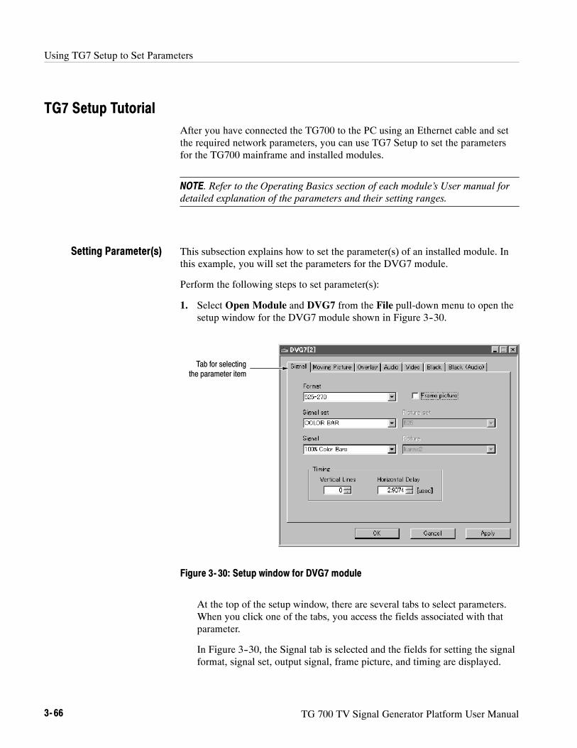
Using TG7 Setup to Set Parameters
3- 66 TG 700 TV Signal Generator Platform User Manual
TG7 Setup TutorialAfter you have connected the TG700 to the PC using an Ethernet cable and setthe required network parameters, you can use TG7 Setup to set the parametersfor the TG700 mainframe and installed modules.
NOTE. Refer to the Operating Basics section of each module’s User manual fordetailed explanation of the parameters and their setting ranges.
This subsection explains how to set the parameter(s) of an installed module. Inthis example, you will set the parameters for the DVG7 module.
Perform the following steps to set parameter(s):
1. Select Open Module and DVG7 from the File pull-down menu to open thesetup window for the DVG7 module shown in Figure 3--30.
Tab for selectingthe parameter item
Figure 3- 30: Setup window for DVG7 module
At the top of the setup window, there are several tabs to select parameters.When you click one of the tabs, you access the fields associated with thatparameter.
In Figure 3--30, the Signal tab is selected and the fields for setting the signalformat, signal set, output signal, frame picture, and timing are displayed.
Setting Parameter(s)

Using TG7 Setup to Set Parameters
TG 700 TV Signal Generator Platform User Manual 3- 67
When you change any parameter in the window, the Apply button at thebottom of the window becomes active. Press this button to enable the newparameter setting(s).
2. Click the tab associated with the parameter you want to set. This opens theparameter fields for that tab.
3. Set parameter(s) in the displayed fields.
4. Repeat Steps 2 and 3 until all of the parameter settings are completed.
5. When you finish making changes to the parameters, click the Apply button.This enables the parameter settings in the setup window and transfers themto the TG700.
NOTE. If you select a signal file or a picture file that is not assigned to a testsignal button on the TG700 front panel, an error message appears when youclick the Apply button. If this happens, you need to assign the file to a test signalbutton. Refer to SIGNAL KEY ASSIGN Submenu on page 3--9 for moreinformation.
When you change parameter(s) for a module that module is selected in theTG700, regardless of what is shown on the display. To prevent addressing thewrong module from the front panel after you exit TG7 Setup, first select any ofthe modules using the MODULE button and then make settings.

Using TG7 Setup to Set Parameters
3- 68 TG 700 TV Signal Generator Platform User Manual

TG 700 TV Signal Generator Platform User Manual 3- 69
Using the File Copy Tools
The file copy tools; TG7 Backup, TG7 Restore, and TG7 Duplicator, standardaccessories with the TG700, are software applications for a PC using theMicrosoft Windows system. TG7 Backup and TG7 Restore provide thecapability to backup and restore preset files between a PC and the TG700 usingthe Ethernet interface. TG7 Duplicator provides the capability to transfer all ofthe files between two TG700 Generators, using the Ethernet interface.
This section provides the following information:
H PC system requirements
H Installation instructions and Ethernet setup
H Starting and exiting the file copy tools
H File copy tools tutorials
PC System RequirementsYour PC requires the following minimum system requirements to load andoperate the file copy tools:
H Microsoft Windows 2000/XP
H Ethernet interface
Installation Instructions and Ethernet SetupThis subsection provides the following instructions: installing the file copy toolson your PC, creating a desktop shortcut icon on the PC to run the file copy tools,and connecting your PC(s) to the TG700 using the Ethernet port.
The following installation instructions assume that you are familiar with thebasics of using the Windows operating system. If necessary, read your Windowsuser documentation before installing the file copy tools.
Perform the following procedure to install the file copy tools:
1. Be sure that your PC meets the requirements listed under PC SystemRequirements, above, before proceeding with the installation.
2. Insert the TG700 Signal Generator Platform Software Library CD-ROMinto a CD-ROM drive on your PC.
Installing the File CopyTools

Using the File Copy Tools
3- 70 TG 700 TV Signal Generator Platform User Manual
3. Double-click theMy computer icon and the CD-ROM drive icon on thePC desktop. The PC will display the contents of the TG700 Signal GeneratorPlatform Software Library CD-ROM.
4. Double-click the Tools folder and TG700 File Copy Tools folder on the PCdesktop. The PC will display the contents of the TG700 File Copy Toolsfolder.
5. Double-click the Setup.exe icon in the folder.
This copies initial files of the file copy tools. For a while, the Welcomewindow appears on the PC desktop.
6. Read the displayed information, and then click the Next> button to proceedwith the installation.
The PC will display the Choose Destination Location window. The defaultdirectory location for the applications is displayed. If you want to install thefile copy tools in a custom location, click the Browse... button, and thenselect or create a custom directory location.
7. Click the Next> button to proceed.
The PC will display the Select Program Folder window. The default namefor the program folder is displayed. If you want to change the name, type ina new name or select a name from the Existing Folders list.
8. Click the Next> button to proceed. The PC will display the Start CopyingFiles window.
9. Click the Next> button to start the installation.
If the installation is successful, the Setup Complete windows is displayed.
Perform the following procedure to create icons on your PC desktop that you canuse to run the file copy tools; TG7 Backup, TG7 Restore, and TG7 Duplicator.
1. On your PC display, move the mouse cursor to any unoccupied desktop area,and then click the right mouse button to open the desktop menu.
2. From the desktop menu select New, and then select Shortcut to open theCreate Shortcut dialog box.
3. Click the Browse... button in the Create Shortcut dialog box.
Creating a DesktopShortcut Icon

Using the File Copy Tools
TG 700 TV Signal Generator Platform User Manual 3- 71
4. Use the Browse dialog box to locate the Logo Generator directory.
a. If you installed the file copy tools using the default directory locationand the default folder name in the installation procedure, select thefollowing directory folders in order: Program Files, Tektronix, Tg7,and File Copy Tools.
b. If you installed the file copy tools to a custom location or gave theapplication folder a custom name, you will need to select your customdirectory path.
c. You should now be at a location in the PC directory structure where thebrowse list box shows the TG7Backup.exe, TG7Duplicator.exe, andTG7Restore.exe files.
5. Select the TG7Backup.exe, TG7Duplicator.exe, or TG7Restore.exe fileand then click the Open button. The directory path to the selected file willnow be displayed in the Command Line box of the Create Shortcut dialogbox.
6. Click the Next> button in the Create Shortcut dialog box. The default nameof the shortcut icon is now displayed in the dialog box. You can edit the iconname to suit your needs or accept the default name.
7. Click the Finish button to finish creating the desktop shortcut icon. Theselected shortcut icon will now appear on the PC desktop. Repeat Steps 1 to6 to create the desktop shortcut icons for the other applications.
You can start any of the application by double-clicking the corresponding(or your custom name) shortcut icon.
TG7 Backup, TG7 Restore, and TG7 Duplicator use the rear-panel 10 BASE-Tport on the TG700 to communicate with a PC or another TG700.
Refer to Connecting to a Network on page 3--15 for detailed information abouthow to connect your PC(s) to the TG700.
Before you can use the TG7 Backup, TG7 Restore, or TG7 Duplicator to transferfiles between the TG700 and your PC(s) or between two TG700 Generators, youmust first set the Ethernet network parameters for the TG700.
NOTE. Use the ping command from the PC to verify network communicationsafter you set the Ethernet network parameters for the TG700 and for the TG7Backup or TG7 Restore application.
Connecting Your PC(s) tothe TG700
Setting Ethernet NetworkParameters

Using the File Copy Tools
3- 72 TG 700 TV Signal Generator Platform User Manual
Ethernet Parameters for the TG700. The Ethernet network parameters for theTG700 can be set using the NETWORK SETUP submenu in the UTILITYmain menu. Refer to Setting Ethernet Network Parameters on page 3--16 fordetailed information about how to set the network parameters.
Starting and Exiting the File Copy ToolsWhen you complete the installation procedure, you can use any of the followingmethods to start the file copy tools:
H Double-click the TG7Backup.exe, TG7 Dupli.exe, or TG7Restore.exeshortcut icon on the PC desktop that you created during the installationprocedure.
H Double-click the TG7Backup.exe, TG7Dupli.exe, or TG7Restore.exe filename in the Program Manager window.
H Select TG7Backup, TG7Dupli, or TG7Restore from the Start -- Programsmenu.
To exit (quit) the TG7 Backup, TG7 Duplicator, or TG7 Restore application,select Exit from the File menu command list of the application.
File Copy Tools TutorialsThis subsection describes the basics of operating the TG7 Backup, TG7 Restore,and TG7 Duplicator applications.
The TG7 Backup application allow you to backup all of the preset files saved inthe TG700 to your PC.
About a Preset File.
A preset file is a file saved in the PRESET folders of all of the installed modulesand has the following format:
MSTATE<slot_number>.P<preset_number>
For example, MSTATE1.P01 is the preset for the module installed in slot 1 of theTG700, with preset number 1.
All of the folders and files in the TG700 file system are displayed using the TG7Comm application. Refer to Using TG7 Comm for File Transfers on page 3--27for detailed information about the TG7 Comm application.
Backing up Preset Filesby TG7 Backup

Using the File Copy Tools
TG 700 TV Signal Generator Platform User Manual 3- 73
Backup Procedure. Perform the following steps to backup all of the preset filesfrom the TG700 to the PC:
1. Start the TG7 Backup application to open the TG7 Backup window shown inFigure 3--31.
Figure 3- 31: TG7 Backup window
2. Use the IP Address field in the window to enter the IP address of theTG700.
3. Use the Save directory field in the dialog box to specify the destinationfolder for the preset files you are going to backup to your PC.
4. Click the Backup button to start the backup operation.
When the backup operation is complete, the dialog box appears as shown inFigure 3--32.
Figure 3- 32: Dialog box shows backup is complete
5. Click the OK button.

Using the File Copy Tools
3- 74 TG 700 TV Signal Generator Platform User Manual
The TG7 Restore application allows you to restore all of the preset files saved inthe PC to the TG700.
NOTE. To restore the all of the preset files to the TG700 and reuse them, thehardware configuration of the TG700 must be the same hardware configurationas when the preset files were backed up.
Perform the following steps to restore all of the preset files from the PC to theTG700:
1. Start the TG7 Restore application to open the TG7 Restore window shown inFigure 3--33.
Figure 3- 33: TG7 Restore window
2. Use the IP Address field in the window to enter the IP address of theTG700.
3. Use the Restore directory field in the dialog box to specify the folder inwhich the preset files are saved.
4. Click the Restore button to start the restore operation.
When the restore operation is complete, the dialog box appears as shown inFigure 3--34.
Figure 3- 34: Dialog box shows restore is complete
Restoring Preset Fileswith TG7 Restore

Using the File Copy Tools
TG 700 TV Signal Generator Platform User Manual 3- 75
5. Click the OK button.
The TG7 Duplicator application allows you to transfer all of the files in oneTG700 to another TG700.
NOTE. To transfer files between the two TG700 using the TG7 Duplicationapplication, both of the instruments need to be the same memory size.
Perform the following steps to transfer all of the files in one TG700 to anotherTG700:
1. Start the TG7 Duplicator application to open the TG7 Duplicator windowshown in Figure 3--35.
Figure 3- 35: TG7 Duplicator window
2. Use the Source IP addr. field in the window to enter the IP address of thesource instrument.
3. Use the Target IP addr. field in the window to enter the IP address of thetarget instrument.
4. Click the Copy button to start the file transfer operation.
The progress gauge appears to show that file transfer is progressing.
CAUTION. Do not power off either of the TG700’s until file transfer is complete.Doing so will cause both instruments to not start up normally.
Transferring Files by TG7Duplicator

Using the File Copy Tools
3- 76 TG 700 TV Signal Generator Platform User Manual
When the file transfer is complete, the dialog box appears as shown inFigure 3--36.
Figure 3- 36: Dialog box shows file transfer is complete
5. Click the OK button.

TG 700 TV Signal Generator Platform User Manual 3- 77
Syntax
This section contains information on the Standard Commands for ProgrammableInstruments (SCPI) and IEEE 488.2 Common Commands you can use toprogram your TG700. The information is organized in the following subsections:
H Programming Model -- This subsection provides information on program-ming prerequisites
H SCPI Commands and Queries -- This subsection describes the SCPIcommand organization and syntax
H IEEE 488.2 Common Commands -- This subsection lists the commands andargument structures that are common to all SCPI commands
H Constructed Mnemonics -- This subsection describes the usage of constructedmnemonics by the TG700.
H Block Arguments -- This subsection describes the usage of block argumentsby the TG700.
H Special Characters -- This subsection lists the special character sets that areused by the remote control interface.

Syntax
3- 78 TG 700 TV Signal Generator Platform User Manual
Programming ModelSpecific conditions must exist before programming commands will affect the testsignal generated by a module.
Select the module to be addressed before executing any commands. Many of thecommands used by the TG700 are shared by several modules and will beaccepted without a reported error.
Many commands accept either string or numeric arguments. For example: aboolean argument can either be “1” or “ON”.
Select signal parameter commands accept either a numeric value or one of thefollowing strings:
MINimum.Use this argument to query the minimum value or set the parametervalue to the minimum acceptable value.
MAXimum.Use this argument to query the maximum value or set the parametervalue to the maximum acceptable value.
DEFault.Use this argument to query the default value or set the parameter valueto the default value.
UP.Use this argument to increase the parameter value one increment as definedby the :STEP value.
DOWN.Use this argument to decrease the parameter value one increment asdefined by the :STEP value.
NOTE. If the TG700 does not return a value in response to a MIN or MAX query,then the values are undefined and an error message is generated.
Addressing Module TestSignals
Command Arguments

Syntax
TG 700 TV Signal Generator Platform User Manual 3- 79
The following example demonstrates the effect of each of the arguments whenused with a step value.
1. :INSTrument:SELect HDVG7:#" selects the HDTV digital video generatormodule located in the slot number indicated by the “#” symbol.
2. :OUTPut:CIRCle:STATe ON displays a circle on the video display.
NOTE. :OUTPut:CIRCle:DIAMeter uses an argument that is the percent ofpicture height.
3. :OUTPut:CIRCle:DIAMeter DEFault sets the circle diameter to 90 percentof the screen height.
4. :OUTPut:CIRCle:DIAMeter:STEP 10 sets the step increment to 10 percent.
5. :OUTPut:CIRCle:DIAMeter DOWN changes the circle diameter to 80 percentof the screen height.
6. :OUTPut:CIRCle:DIAMeter 50 changes the circle diameter to 50 percent ofthe screen height.
7. :OUTPut:CIRCle:DIAMeter MAXimum changes the circle diameter to100 percent of the screen height.
8. :OUTPut:CIRCle:DIAMeter MINimum changes the circle diameter to0 percent of the screen height.
9. :OUTPut:CIRCle:DIAMeter UP changes the circle diameter to 10 percent ofthe screen height.
10. :OUTPut:CIRCle:DIAMeter? MAXimum queries the maximum circlediameter (not the current diameter). The query returns the value of100 percent, which is the maximum circle diameter allowable.
Argument Example

Syntax
3- 80 TG 700 TV Signal Generator Platform User Manual
SCPI Commands and QueriesSCPI is a standard created by a consortium that provides guidelines for remoteprogramming of instruments. These guidelines provide a consistent program-ming environment for instrument control and data transfer. This environmentuses defined programming messages, instrument responses, and data formatacross all SCPI instruments, regardless of manufacturer. The TG700 uses acommand language based on the SCPI standard.
The SCPI language is based on a hierarchical or tree structure (see Figure 3--37)that represents a subsystem. The top level of the tree is the root node; it isfollowed by one or more lower-level nodes.
DIAMeter
OUTPut
CIRCle
POSitionSTATe
Root node
Lower-levelnodes
Figure 3- 37: Example of SCPI subsystem hierarchy tree
You can create commands and queries from these subsystem hierarchy trees.Commands specify actions for the instrument to perform. Queries returnmeasurement data and information about parameter settings.
SCPI commands are created by stringing together the nodes of a subsystemhierarchy and separating each node by a colon.
In Figure 3--37, OUTPut is the root node and CIRCle, STATe, DIAMeter, andPOSition are lower-level nodes. To create a SCPI command, start with the rootnode OUTPut and move down the tree structure adding nodes until you reach theend of a branch. Most commands and some queries have parameters; you mustinclude a value for these parameters. If you specify a parameter value that is outof range, the parameter will be set to a default value.
For example, OUTPut:CIRCle:STATe ON is a valid SCPI command createdfrom the hierarchy tree in Figure 3--37.
To create a query, start at the root node of a tree structure, move down to the endof a branch, and add a question mark. OUTPut:CIRCle:STATe? is an example ofa valid SCPI query using the hierarchy tree in Figure 3--37.
Creating Commands
Creating Queries

Syntax
TG 700 TV Signal Generator Platform User Manual 3- 81
Every parameter in the command and query descriptions is of a specified type.The parameters are enclosed in brackets, such as <pattern>. The parameter typeis listed after the parameter and is enclosed in parentheses, for example,(discrete). Some parameter types are defined specifically for the TG700command set and some are defined by ANSI/IEEE 488.2-1987 (see Table 3--23).
Table 3- 23: Parameter types used in syntax descriptions
Parameter Type Description Example
binary Binary numbers #B0110
arbitrary block1 A specified length of arbitrarydata
#512234xxxxx . . . where 5indicates that the following 5digits (12234) specify the lengthof the data in bytes; xxxxx ...indicates the data
boolean Boolean numbers or values ON or 1OFF or 0
discrete A list of specific values MIN, MAX, UP, DOWN
hexadecimal2 Hexadecimal numbers(0--9, A, B, C, D, E, F)
#HAA, #H1
NR12,3 numeric Integers 0, 1, 15, --1
NR22 numeric Decimal numbers 1.2, 3.141516, --6.5
NR32 numeric Floating point numbers 3.1415E--9, --16.1E5
NRf2 numeric Flexible decimal number thatmay be type NR1, NR2 or NR3
See NR1, NR2, NR3 examples
string4 Alphanumeric characters (mustbe within quotation marks)
“Testing 1, 2, 3”
1 Defined in ANSI/IEEE 488.2 as “Definite Length Arbitrary Block Response Data.”2 An ANSI/IEEE 488.2- 1992-defined parameter type.3 Some commands and queries will accept a hexadecimal value even though the
parameter type is defined as NR1.4 Defined in ANSI/IEEE 488.2 as “String Response Data.”
Parameter Types

Syntax
3- 82 TG 700 TV Signal Generator Platform User Manual
You can abbreviate most SCPI commands, queries, and parameters to anaccepted short form. This manual shows these short forms as a combination ofupper and lower case letters. The upper case letters indicate the accepted shortform of a command. As shown in Figure 3--38, you can create a short form byusing only the upper case letters. The accepted short form and the long form areequivalent and request the same action of the instrument.
Long form of acommand
Minimum information neededfor accepted short form
Accepted short formof a command and
parameter
OUTP:EAUD:CHAN2:AMPL 10
OUTPut:EAUDio:CHANnel2:AMPLitude 10
Figure 3- 38: Example of abbreviating a command
NOTE. The numeric suffix of a command or query may be included in either thelong form or short form; the TG700 will default to “1” if no suffix is used. InFigure 3--38, the “2” of “CHAN2” indicates that the command is directed to thesecond channel..
Abbreviating Commands,Queries, and Parameters

Syntax
TG 700 TV Signal Generator Platform User Manual 3- 83
You can chain several commands or queries together into a single message. Tocreate a chained message, first create a command or query, add a semicolon (;),and then add more commands or queries and semicolons until you are done. Ifthe command following a semicolon is a root node, precede it with a colon (:).Figure 3--39 illustrates a chained message consisting of several commands andqueries. The single chained message should end in a command or query, not asemicolon. Responses to any queries in your message are separated by semico-lons.
:OUTP:CIRC:DIAM 75;:OUTP:EAUD:STAT ON;:OUTP:EAUD:GRRO:NBIT?;:OUTP:LOGO:POS:HOR?
First command Second command Second query
The response from this chainedmessage might be
Response from first query Response from second query
24;-35
First query
Figure 3- 39: Example of chaining commands and queries
If a command has the same root and lower-level nodes as the previous command,you can omit these nodes. In Figure 3--40, the second command has the sameroot node (CIRC) as the first command, so these nodes can be omitted.
Identical root and lower-level nodes
First command Additional commands(omitting the root nodes)
:OUTP:CIRC:DIAM 25;:OUTP:CIRC:POS:VERT 25;:OUTP:CIRC:STAT ON
:OUTP:CIRC:DIMA 25;POS:VERT 25;STAT ON
Figure 3- 40: Example of omitting root and lower-level nodes in a chained message
Chaining Commands andQueries

Syntax
3- 84 TG 700 TV Signal Generator Platform User Manual
Here are three general rules for using SCPI commands, queries, and parameters:
H You can use single (‘ ’) or double (“ ”) quotation marks for quoted strings,but you cannot use both types of quotation marks for the same string.
correct: “This string uses quotation marks correctly.”
correct: ‘This string also uses quotation marks correctly.’
incorrect: “This string does not use quotation marks correctly.’
H You can use upper case, lower case, or a mixture of both cases for allcommands, queries, and parameters.
OUTPUT:TEXT:POSITION:HORIZONTAL 25
is the same as
output:text:position:horizontal 25
and
OUTPUT:text:position:HORIZONTAL 25
NOTE. Literal strings (quoted) are case sensitive. For example: file names.
H No embedded spaces are allowed between or within nodes.
correct: OUTPUT:TEXT:POSITION:HORIZONTAL 25
incorrect: OUTPUT: TEXT: POSITION: HOR IZONTAL 25
General Rules

Syntax
TG 700 TV Signal Generator Platform User Manual 3- 85
IEEE 488.2 Common Commands
ANSI/IEEE Standard 488.2 defines the codes, formats, protocols, and usage ofcommon commands and queries used on the interface between the controller andthe instruments. The TG700 complies with this standard.
The syntax for an IEEE 488.2 common command is an asterisk (*) followed by acommand and, optionally, a space and parameter value. The syntax for anIEEE 488.2 common query is an asterisk (*) followed by a query and a questionmark. All of the common commands and queries are listed in the last part of theSyntax and Commands section. The following are examples of commoncommands:
H *ESE 16
H *CLS
The following are examples of common queries:
H *ESR?
H *IDN?
This manual may describe commands and queries using the Backus-Naur Form(BNF) notation. Table 3--24 defines the standard BNF symbols:
Table 3- 24: BNF symbols and meanings
Symbol Meaning
< > Defined element
::= Is defined as
| Exclusive OR
Group; one element is required
[ ] Optional; can be omitted
. . . Previous element(s) may be repeated
( ) Comment
This manual uses <EOM> (End of message) to represent a message terminator.
Symbol Meaning
<EOM> Message terminator
Description
Command and QueryStructure
Backus-Naur FormDefinition
Message Terminators

Syntax
3- 86 TG 700 TV Signal Generator Platform User Manual
The end-of-message terminator may be the ASCII code for line feed (LF) sent asthe last data byte. The TG700 always terminates messages with LF. It allowswhite space before the terminator.
Constructed MnemonicsSome header mnemonics specify one of a range of mnemonics. For example, anaudio channel mnemonic can be either CHANnel1, CHANnel2, CHANnel3, orCHANnel4.You use these mnemonics in the command just as you do any othermnemonic. For example, there is a :OUTP:EAUD:CHAN1:STAT? query, and thereis also an :OUTP:EAUD:CHAN2:STAT? query. In the command descriptions, thislist of choices is abbreviated as CHANnel<n>. The value of <n> is the upper rangeof valid suffixes. If the numeric suffix is omitted, the TG700 uses the defaultvalue of “1”.
Block ArgumentsSeveral TG700 commands use a block argument form:
Symbol Meaning
<NZDig> A non-zero digit character, in the range 1--9
<Dig> A digit character, in the range 0--9
<DChar> A character with the hex equivalent of 00 through FFhexadecimal (0 through 255 decimal)
<Block> A block of data bytes, defined as:
<Block> ::= #<NZDig><Dig>[<Dig>...][<DChar>...]| #0[<DChar>...]<terminator>
<NZDig> specifies the number of <Dig> elements that follow. Taken together, the<Dig> elements form a decimal integer that specifies how many <DChar>elements follow.

Syntax
TG 700 TV Signal Generator Platform User Manual 3- 87
Special CharactersThe remote control interface handles characters differently than the front panel orSDP2000 software.
Standard symbol (ASCII) Remote control sequence
/ (47) ‘s
\ (92) ‘b
-- (45) ‘h
‘ (96) ’’
: (58) ‘c
Line return ^ (94)
Signal names created from SDP2000 software will be displayed as created.Signals created or displayed using the SCPI interface use the remote controlsequence.
For example: “SinX/X” is displayed as “SinX/X” via the front panel or SDP2000software; however, “SinX/X” is displayed as “SinX‘sX” via when using SCPI.
Use the caret symbol “^” as a line return when naming buttons and signals.

Syntax
3- 88 TG 700 TV Signal Generator Platform User Manual

TG 700 TV Signal Generator Platform User Manual 3- 89
Remote Commands
This section describes the remote command set used in the TG700. Thecommands for the TG700 are divided into the following eight groups:
H Common commands
H DISPLAY commands
H INSTRUMENT commands
H MASS MEMORY commands
H PROGRAM commands
H SENSE commands
H STATUS commands
H SYSTEM commands
The TG700 can be controlled remotely through the Ethernet interface on the rearpanel. Refer to Connecting to a Network on page 3--15 for detailed informationabout how to connect and set up for remote operation.
Common CommandsThe Common commands have a “*” prefix and address all of the installedmodules.
*CLS*ESE(?)*ESR?*IDN?*OPC(?)*OPT?*RST*SRE(?)*STB?*TST?*WAI
Command Tree

Remote Commands
3- 90 TG 700 TV Signal Generator Platform User Manual
*CLS
Clears SESR (Standard Event Status Register), the SBR (Status ByteRegister), and Event Queue, which are used in the instrument statusand event reporting system.
*ESE
Sets the bits of the ESER (Event Status Enable Register) used in thestatus and events reporting system.
*ESE?
Returns the contents of the ESER.
*ESR?
Returns the contents of SESR (Standard Event Status Register) usedin the status and events reporting system.
*IDN?
Returns the ID information of the instrument.
*OPC
Causes bit 0 in the SESR (Standard Event Status Register) to be set ,and the operation complete message to be issued, when all pendingoperations are finished.
*OPC?
Waits until all pending operations are finished and returns a “1 ”ASCII character.
*OPT?
Lists all of the occupied slots in the TG700 and the nomenclature,slot, hardware version, and software version of the installedmodules.
Each field is a slot. Each field is separated by commas. Theinformation within a field is colon delimited, as in “<nomencla-ture>:<slot>:<hw>:<sw>”.
*RST
Resets the instrument to the default state.
Command Description

Remote Commands
TG 700 TV Signal Generator Platform User Manual 3- 91
*SRE
Sets the bits of the SRER (Service Request Enable Register).
*SRE?
Returns the contents of SRER.
*STB?
Returns the value of the SBR (Status Byte Register). Bit 6 of theSBR is read as a MSS (Master Status Summary) bit.
*TST?
Self-test query. This query does not perform any tests; however, thisquery is accepted as a valid command to comply with IEEE 488.2requirements.
*WAI
Wait-to-continue command. This command is not necessary sincethe TG700 handles commands sequentially; however, this query isaccepted as a valid command to comply with IEEE 488.2 require-ments.
DISPLAY CommandsUse these commands to control the contrast and backlight settings of the LCDdisplay.
:DISPlay:BACKlight ON|OFF:CONTrast <numeric_value>[:WINDow][:TEXT][:DATA] <message>
:DISPlay:BACKlight ON|OFF
Turns the LCD display backlight on or off. You can use 1 or 0instead of ON or OFF.
:DISPlay:BACKlight?
Returns the current status of the backlight.
Command Tree
Command Description

Remote Commands
3- 92 TG 700 TV Signal Generator Platform User Manual
:DISPlay:CONTrast <numeric_value>
Controls the intensity of the front-panel LCD display. The valueshould be an integer number between 1 and 40.
:DISPlay:CONTrast?
Returns the current contrast value.
INSTRUMENT CommandsUse these commands to list, identify, and query modules.
:INSTrument:CATalog?:FULL?
[:SELect] <module_name>:NSELect <slot_number>
:INSTrument:CATalog?
Returns a comma delimited list of all slots that are occupied bymodules.
:INSTrument:CATalog:FULL?
Returns a comma delimited list of module names and slot numbers,in pairs. The string type of module and the numeric suffix indicatesthe slot. For example, “AGL7:1”, 1, “HDVG7:2”, 2 indicates aAGL7 in slot 1, and a HDVG7 in slot 2.
:INSTrument:[:SELect] <module_name>
Selects a module by name.
:INSTrument:[:SELect]?
Returns a module by name.
:INSTrument:NSELect <slot_number>
Select a module by slot number.
Command Tree
Command Description

Remote Commands
TG 700 TV Signal Generator Platform User Manual 3- 93
:INSTrument:NSELect?
Returns a module by slot number.
MASS MEMORY CommandsAll signal movement within the memory is accomplished by copying allappropriate files of the named signal(s) to the new location. The signal tree istraversable and the use of wildcards permits copying or storing individual signalsor the entire module signal list.
:MMEMory:CATalog? [<directory_path>]:CDIRectory <directory_path>:COPY <source>,<destination>:DATA <file_name>,<block_data>:DELete <file_name>:LOAD:DOWNload <block_data>:PRESet <preset_ID>|<preset_name>:SIGNal <module_name>,<signal_name>
:MDIRectory <directory_path>:MOVe <from_filename>,<to_filename>:RDIRectory <directory_path>:SIGNal:ACTive? <signal_name>
:STORe:PRESet <preset_ID>|<preset_name>
:PRESet:CATalog? <preset_ID>:ALL?
:DELete <preset_ID>|<preset_name>:REName <preset_ID>,<preset_name>
The argument <signal_name> is the full or partial path name to a signal found ina module. The argument <file_name> is the MS-DOS compatible namingconvention. For example, the syntax for a complete path would be:
module_type/signal_set/button/test_signal
H module_type is the directory level for a given module type
H signal_set is the directory level for different sets of signals
H button is the directory level for different buttons
H test_signal is the directory level for different test signals
Command Tree

Remote Commands
3- 94 TG 700 TV Signal Generator Platform User Manual
:MMEMory:CATalog? [<directory_path>]
Lists the current directory level. If at the top level, it returns a list ofsignal sets and the other files and directories for the module partitionyou are currently in. If in a Signal Set directory, it returns a list ofbuttons. If in a button directory, it returns a list of test signals.
Query response -- <used_bytes>, <available_bytes>, <file_name1>,,<file_size1>, <file_name2>,, <file_size2>
:MMEMory:CDIRectory [<directory_path>]
Changes the current working directory.
:MMEMory:CDIRectory?
Returns the current working directory path.
:MMEMory:COPY <source>,<destination>
Copies a file within the TG700 file system. Wildcards are notsupported.
This command is provided to support sequence files and is notrecommended for use with signal files.
:MMEMory:DATA <file_name>,<block_data>
Loads data created by a PC to the flash memory of the TG700 withthe specified file name. The file name should have an appropriateextension.
:MMEMory:DATA? <file_name>
Lists the block data for the specified file name.
:MMEMory:DELete <file_name>
Removes files from the flash memory of the TG700.
:MMEMory:LOAD:DOWNload <block_data>
Adds DNL files to the TG700.
:MMEMory:LOAD:PREset <preset_ID>|<preset_name>
Loads a saved preset. This command accepts the name of apreviously saved preset. Current instrument settings are overwrittenby this command. The preset_IDs are from 0 to 15; 0 represents thePower on Default, 1 to 13 represent ordinary presets, 14 representsthe User Default, and 15 represents the Factory Default.
Command Description

Remote Commands
TG 700 TV Signal Generator Platform User Manual 3- 95
:MMEMory:LOAD:SIGNal <module_name>,<signal_name>:MMEMory:LOAD:SIGNal <slot_number>,<signal_name>
Loads the named signal into the named module. The current signalin the module is overwritten.
:MMEMory:MDIRectory <directory_name>
Creates a directory by the given name.
:MMEMory:MOVe <from_filename>,<to_filename>
Changes the name of the specified file.
:MMEMory:RDIRectory <directory_name>
Removes the specified directory from the file system.
:MMEMory:SIGNal:ACTive? <slot_number>|<module_name>
Lists the current output signal in the specified module.
:MMEMory:STORe:PRESet <preset_ID>|<preset_name>
Saves all the instrument settings with the specified preset ID orpreset name. The preset_IDs are from 0 to 15; 0 represents thePower on Default, 1 to 13 represent ordinary presets, 14 representsthe User Default, and 15 represents the Factory Default.
:MMEMory:PRESet:CATalog? <preset_ID>
Lists the name of the specified preset saved in the TG700. Thepreset_IDs are from 0 to 15; 0 represents the Power on Default, 1 to13 represent ordinary presets, 14 represents the User Default, and 15represents the Factory Default.
:MMEMory:PRESet:CATalog:ALL?
Lists the names of all presets saved in the TG700.
:MMEMory:PRESet:DELete <preset_ID>|<preset_name>
Deletes the specified preset saved in the TG700. The preset_IDs arefrom 0 to 15; 0 represents the Power on Default, 1 to 13 representordinary presets, 14 represents the User Default, and 15 representsthe Factory Default.
:MMEMory:PRESet:REName <preset_ID>,<preset_name>
Renames the specified preset saved in the TG700. The preset_IDsare from 0 to 15; 0 represents the Power on Default, 1 to 13represent ordinary presets, 14 represents the User Default, and 15represents the Factory Default.

Remote Commands
3- 96 TG 700 TV Signal Generator Platform User Manual
PROGRAM CommandsUse these commands to access and run programs called “sequences”.
:PROGram[:SELected]?:NAME <progname>:STATe RUN|PAUSe|STOP|CONTinue:WAIT?
:EXPLicit:STATe <progname>,RUN|PAUSe|STOP|CONTinue:WAIT?
:PROGram[:SELected]:NAME <program>
Selects the default sequence file.
:PROGram[:SELected]:NAME?
Returns the name of the default sequence file.
:PROGram[:SELected]:STATe RUN|PAUSe|STOP|CONTinue
Controls execution of the default sequence. The choices are Run,PAUSe, STOP, and CONTinue.
:PROGram[:SELected]:STATe?
Returns the condition of the execution of the default sequence.
:PROGram[:SELected]:WAIT
Holds off further commands until the default sequence completes.
:PROGram[:SELected]:WAIT?
If sequence has terminated or paused, this returns 1. If sequence isrunning, this returns 0.
:PROGram:EXPLicit:STATe <progname> RUN|PAUSe|STOP|CONTinue
Controls execution of the specified sequence. The choices are RUN,PAUSe, STOP, and CONTinue.
:PROGram:EXPLicit:STATe? <progname>
Returns the condition of the execution of the specified sequence.
Command Tree
Command Description
Remote Commands
TG 700 TV Signal Generator Platform User Manual 3- 97
:PROGram:EXPLicit:WAIT <progname>
Holds off further commands until the specified sequence completes.
:PROGram:EXPLicit:WAIT? <progname>
If sequence has terminated or paused, this returns 1. If sequence isrunning, this returns 0.
SENSE CommandsUse these queries to list which generator modules are using which frame resetsignals.
:SENSe:ROSCillator:FRAMe[3]:CATalog?:FREQuency?
:SENSe:ROSCillator:FRAMe<n>:CATalog?
Lists the modules using the frame reset signal <n>. The suffixidentifies which of three frame reset signals to query.
:SENSe:ROSCillator:FRAMe<n>:FREQuency?
Lists the specific frame reset signal frequency.
Command Tree
Command Description

Remote Commands
3- 98 TG 700 TV Signal Generator Platform User Manual
STATUS CommandsUse these commands to address the instrument status and event queue.
:STATus:OPERation[:EVENt]?:CONDition?:ENABle <numeric_value>:PTRansition <numeric_value>:NTRansition <numeric_value>:MAP <numeric_value>, <numeric_value>:INSTrument[:EVENt]?:CONDition?:ENABle <numeric_value>:PTRansition <numeric_value>:NTRansition <numeric_value>
:PRESet:QUEue[:NEXT]:ENABle
:QUEStionable[:EVENt]?:CONDition?:ENABle <numeric_value>:PTRansition <numeric_value>:NTRansition <numeric_value>:MAP <numeric_value>, <numeric_value>:INSTrument[:EVENt]?:CONDition?:ENABle <numeric_value>:PTRansition <numeric_value>:NTRansition <numeric_value>
Command Tree

Remote Commands
TG 700 TV Signal Generator Platform User Manual 3- 99
PRESet. The OPERation node covers areas of instrument operational events. Thisnode reports such items as signal settling, calibration, or running a sequence
QUEStionable. The QUEStionable node covers areas of questionable conditionsthat exist within the instrument. Questionable conditions might cause you to beunsure of the quality of the generated signals.
Subnodes. Each node has a set of subnodes that query the contents, or control theinvolvement, of each bit.
H ENABle selects which bits are active in reporting the status.
H EVENt is a destructive query only of the status.
H CONDition is a nondesctructive query only of the status.
H PTRansition allows a status to become true on a positive transition of theevent.
H NTRansition allows a status to become true on a negative transition of theevent.
H MAP reassigns event reporting at the top level of the status hierarchy.
H INSTrument. Both main nodes have this sub node that summarizes theoperational and questionable condition of the instrument. Each bit in thesetwo registers represents a slot in the TG700. The summation of each registerwill feed into bit 13 of its respective parent register.
PRESet.All of the enable registers are set to TRUE so that they return topower-up conditions.
QUEue.QUEue:ENABle enables certain events or error conditions to be reported.Values that are not explicitly specified are not reported.STATus:QUEue[:NEXT?] is the same as SYSTem:ERRor?.
Due to the repetitiveness of this subsystem, the details will be covered for thenodes EVENt, CONDition, ENABle, PTRansition, NTRanstion, and MAP. Thesyntax and examples do not include the full command. Refer to the CommandTree to derive what commands would be appropriate. The following text thendescribes each major branch within the STATus subsystem.
Command Description

Remote Commands
3- 100 TG 700 TV Signal Generator Platform User Manual
[:EVENt]?
Performs a destructive reading of the specific event status register.The contents are cleared by reading or by *CLS.
:CONDition?
Performs a nondestructive reading of the specified condition register.Contents are cleared as a result of *CLS.
:ENABle <numeric_value>
Sets the register that enables the individual bits within the EventRegister, which records event transition.
:ENABle?
Returns the current Event Register settings.
:PTRansition <numeric_value>
Sets the transistion register for enabling events to set bits true duringa positive transition.
:PTRansition?
Returns the transistion register for enabling events to set bits trueduring a positive transition.
:NTRansition <numeric_value>
Sets the transition register for enabling events to set bits true duringa negative transition.
:NTRansition?
Returns the transition register for enabling events to set bits trueduring a negative transition.
:STATus:OPERation:MAP <bit>,<event>:STATus:QUEStionable:MAP <bit>,<event>
Reassigns events to bits in the OPERation or QUEStionableregisters.

Remote Commands
TG 700 TV Signal Generator Platform User Manual 3- 101
SYSTEM CommandsUse these commands to query the system related information and set thefront-panel lock function.
:SYSTem:ERROR[:NEXT]?
:HELP:SYNTax?
:KLOCk:STATe ON|OFF
:VERSion?
:SYSTem:ERRor?
Lists the next event in the Error/Event queue. Queue is cleared atpower up, upon *CLS, and upon reading the last item.
:SYSTem:HELP:SYNTax?
Lists correct command syntax.
:SYSTem:KLOCk:STATe ON|OFF
Locks or unlocks the front-panel buttons. You can use 1 or 0 insteadof ON or OFF.
:SYSTem:KLOCk:STATe?
Returns the current status of the front-panel buttons.
:SYSTem:VERSion?
Lists the SCPI compliance version. Query only.
Command Tree
Command Description

Remote Commands
3- 102 TG 700 TV Signal Generator Platform User Manual

TG 700 TV Signal Generator Platform User Manual 3- 103
Sequence Programming
Sequence programs enable the TG700 to execute routines using SCPI com-mands. The TG700 accepts sequences written using the Tcl programminglanguage.
Writing a Sequence ProgramSequence programs can be created externally to the TG700 using Tcl program-ming and loaded via Ethernet interface into the file system of the TG700.Sequences can also be loaded through SCPI commands using the PROGramsubsystem commands.
A sequence program can be very simple or it can contain many steps. A runningsequence program is interpreted by the Tcl parser and some Tcl formattinginformation is required. A few points are mentioned here to show why they areused in the sample. Full information on Tcl programming is found in Part 1 ofTcl and the Tk Toolkit: Addison--Wesley Publishing Company, 1994.
H Comments in Tcl sequences are preceded by the # symbol as the firstnonblank character in the line. The # symbol appearing in the line at otherlocations is treated as any other character.
H SCPI commands that use double quote marks require an escape backslash(\“string\”) in order to pass to SCPI using the Tcl scpi command.
H SCPI commands should all be preceded with the string “scpi ”.
Running a SequenceWhen you run a sequence, you need to download the corresponding sequence file(.seq) to the SEQUENCE folder (/F0:/SEQUENCE directory) of the TG700 inadvance. Stored sequences can be called and started from the SEQUENCE mainmenu.
Refer to Using TG7 Comm for File Transfers on page 3--27 for instructions onhow to download a sequence file.
Running a sequence from remote control using SCPI commands requires thefollowing steps:

Sequence Programming
3- 104 TG 700 TV Signal Generator Platform User Manual
1. Use the PROG:SEL:NAME <progname> command to select the sequenceprogram to run.
You can also use the PROG:EXPL:STAT <progname>,RUN command atthis point to start the sequence named explicitly.
The syntax of the <progname> file can be used without quotes, unless aperiod is used in the name to separate the base from the extension. If a fileextension is used, then quotes are required to convey the name to the TG700.
Examples:
prog:expl:stat test1,runprog:name ”t_0044.tcl”
2. Use the PROG:SEL:STAT RUN command to start the named sequence.Send PROG:SEL:STAT STOP to stop the running sequence if is is not selfterminating.
Tcl Programming ChangesThe TG700 uses the following extended Tcl commands:
sleep <seconds> [<tenths> [<hundredths>]]
Delay for the specified seconds and optional tenths and hundredths of seconds
scpi
Specifies that the command following is a SCPI command. The Tcl parser passesit immediately to the SCPI command interpreter.
Command:
Usage:
Command:
Usage:

Appendices


TG 700 TV Signal Generator Platform User Manual A-1
Appendix A: Specifications
Tables A-1 through A-3 list the electrical, environmental, and mechanicalcharacteristics of the TG 700 mainframe. For the specifications of a specificgenerator module or other module, refer to the module User manual. Table A-4lists the certification and compliances.
The performance requirements listed in the electrical characteristics portion ofthese specifications apply over an ambient temperature range of 0 °C to +50 °C.The rated accuracies are valid when the instrument is calibrated at an ambienttemperature range of +20 °C to +30 °C, after a warm-up time of 20 minutes.
Electrical Characteristics
Table A-1: Electrical characteristics
Characteristic Performance requirements Reference information
The number of modules that can beinstalled
Maximum 4 Only a limited number of some modules canbe installed in a TG700 mainframe:
AGL7 Maximum 1AVG7 Maximum 2AWVG7 Maximum 2HDVG7 Maximum 2
Clock
Stability <1 ppm/yearAC power source
Rating voltage 100 V to 240 VAC
Voltage range 85 V to 250 VAC
Frequency range 48 Hz to 63 Hz
Maximum power 100 W
Maximum current 1.2 A
Heat Dissipation
Maximum power 100 W maximum. Maximum line current is1.2 A rms at 50 Hz
Surge current ≤ 40 A peak for equal or less than 5 linecycles, after the instrument has been turnedoff for at least 30 seconds.
Clearance
Side 5 cm
Rear 5 cm

Appendix A: Specifications
A-2 TG 700 TV Signal Generator Platform User Manual
Environmental Characteristics
Table A-2: Environmental characteristics
Characteristic Description
Temperature
Operating 0 _C to +50 _C
Nonoperating --20 _C to +60 _C
Relative Humidity
Operating 20% to 80% (No condensation)Maximum wet-bulb temperature 29.4 _C
Nonoperating 5% to 90% (No condensation)Maximum wet-bulb temperature 40.0 _C
Altitude
Operating To 4.5 km (15,000 feet)Maximum operating temperature decreases 1 _C each 300 m above 1.5 km.
Nonoperating To 15 km (50,000 feet)
Vibration
Operating 2.65 m/s2 (0.27 Grms), 5 Hz to 500 Hz, 10 min, three axes
Nonoperating 22.3 m/s2 (2.28 Grms), 5 Hz to 500 Hz, 10 min, three axes
Shock
Nonoperating 294 m/s2 (30 G), half-sine, 11 ms duration
Mechanical Characteristics
Table A-3: Mechanical characteristics
Characteristic Description
Dimensions
Height 44 mm
Width 483 mm
Depth 559 mm
Weight1
Net Approximately 5.5 kg (mainframe only, without rack rail)1 Weight of the TG 700 will vary depending on the number and type of generator or other modules installed.

Appendix A: Specifications
TG 700 TV Signal Generator Platform User Manual A-3
(mm)
Figure A-1: TG700 dimensions

Appendix A: Specifications
A-4 TG 700 TV Signal Generator Platform User Manual
Certifications and Compliances
Table A-4: Certifications and compliances
Category Standard or description
EC Declaration of Conformity --EMC
Meets the intent of Directive 89/336/EEC for Electromagnetic Compatibility. Compliancewas demonstrated to the following specifications as listed in the Official Journal of theEuropean Communities:C
EN 55103-1 Emissions:EN 55022 Class B Radiated and Conducted EmissionsEN 55103-1 Annex A Magnetic Field EmissionsEN 55103-1 Annex B Power Line Inrush CurrentEN 61000-3-2 AC Power Line Harmonic Current EmissionsEN 61000-3-3 Line Voltage Alteration and Flicker
EN 55103-2 Immunity:EN 61000-4-2 Electrostatic Discharge ImmunityEN 61000-4-3 RF Electromagnetic Field Amplitude ModulatedEN 61000-4-4 Electrical Fast Transient/Burst ImmunityEN 61000-4-5 AC Mains Surge ImmunityEN 61000-4-6 Conducted RF ImmunityEN 61000-4-8 Power Frequency Electromagnetic Field ImmunityEN 61000-4-11 Mains Voltage Dip & Interruption ImmunityEN 55103-2 Annex A Magnetic Field Immunity
High--quality shielded cables must be used to ensure compliance to the above listedstandards.
Australia/New Zealand Declaration ofConformity -- EMC
Complies with EMC provision of Radiocommunications Act per the following standard(s):
AS/NZS 3548 Industrial, Scientific, and Medical Equipment: 1992
Safety Complies with the following safety standards/regulations:
UL 3111-1
CSA C22.2 No.1010.1
EN 61010-1 with second amendment
Installation (Overvoltage) Category Terminals on this product may have different installation (overvoltage) category designa-tions. The installation categories are:
CAT III Distribution-level mains (usually permanently connected). Equipment at this levelis typically in a fixed industrial location.
CAT II Local-level mains (wall sockets). Equipment at this level includes appliances,portable tools, and similar products. Equipment is usually cord-connected.
CAT I Secondary (signal level) or battery operated circuits of electronic equipment.

Appendix A: Specifications
TG 700 TV Signal Generator Platform User Manual A-5
Table A-4: Certifications and compliances (cont.)
Category Standard or description
Pollution Degree A measure of the contaminates that could occur in the environment around and within aproduct. Typically the internal environment inside a product is considered to be the same asthe external. Products should be used only in the environment for which they are rated.
Pollution Degree 2 Normally only dry, nonconductive pollution occurs. Occasionally atemporary conductivity that is caused by condensation must beexpected. This location is a typical office/home environment.Temporary condensation occurs only when the product is out ofservice.
IEC Characteristics Equipment type:
Test and MeasuringInstallation Category II (as defined in IEC 61010-1, Annex J)Pollution Degree 2 (as defined IEC 61010-1)Safety Class1 (as defined in IEC 61010-1, Annex H)--grounded product

Appendix A: Specifications
A-6 TG 700 TV Signal Generator Platform User Manual

TG700 TV Signal Generator Platform User Manual B-1
Appendix B: Module Installation
This section provides instructions for installing and removing modules from theTG700 mainframe. A screwdriver with a #1 Phillips tip is the only tool you needto install or remove a module.
CAUTION. To prevent damage to the mainframe and module, always remove thepower cord before installing or removing a module.
Preventing Component Damage
CAUTION. Electrostatic discharge (ESD) can damage components on this moduleand mainframe. To prevent ESD or other component damage, follow the stepsbelow when installing, removing, or handling modules:
1. Wear a grounded antistatic wrist strap to discharge the static voltage fromyour body while installing or removing modules from the TG700 mainframe.
2. Transport and store modules in a static-protected bag or container.
3. Do not slide the module over any surface.
4. Handle modules as little as possible.
5. Do not touch module components or connector pins.
6. Do not use any devices capable of generating or holding a static charge in thework area where you remove, install, or handle modules.
7. Avoid handling modules in areas that have a floor or work-surface coveringcapable of generating a static charge.
8. Do not remove the module circuit board assembly from the shield. Theshield is an important stiffener which prevents damage to surface-mountcomponents.

Appendix B: Module Installation
B-2 TG700 TV Signal Generator Platform User Manual
Installing a ModuleTo install a module into the mainframe perform the following procedure:
1. Unplug the power cord from the power connector on the rear panel of themainframe.
2. Select the slot you will use to install the module. Figure B-1 shows a sampleconfiguration with slot numbers.
NOTE. Only one AGL7 module can be installed in the TG700 mainframe, and itmust only be installed in slot 1. All other modules may be installed in any slotlocation.
4 3 2 1
AG7 HDVG7 DVG7 AGL7
Figure B-1: TG700 slot numbering
NOTE. Any number (up to 4) of the following modules can be installed in theTG700 mainframe:
AG7ATG7BG7DVG7HDVG7
Only a combined total of two (2) of the following modules can be installed in theTG700 mainframe at the same time:
AVG7AWVG7HDVG7
3. Use a screwdriver with a #1 Phillips tip to loosen the two screws on theblank panel attached to the slot you want to use, and then pull it away.See Figure B-2.

Appendix B: Module Installation
TG700 TV Signal Generator Platform User Manual B-3
Figure B-2: Removing the blank panel
CAUTION. Be careful not to damage the parts and cables inside of the modulewhen you insert the module into the mainframe.
4. Insert the module into the slot, paying attention to the module orientation.See Figure B-3.
Figure B-3: Installing the module

Appendix B: Module Installation
B-4 TG700 TV Signal Generator Platform User Manual
5. Push the module in until the connector board of the module is firmlyengaged with the main board of the mainframe.
6. Tighten the two screws to secure the module to the mainframe.See Figure B-4.
Figure B-4: Securing the module
Removing a moduleTo remove a module from the mainframe perform the following procedure:
CAUTION. To make module removal easy, attach terminations or BNC cables tothe module connectors. The connector may be damaged if too much force isapplied to it during module removal.
1. Unplug the power cord from the power connector on the mainframe rearpanel.
2. Attach 75 Ω terminations or BNC cables to the BNC connectors on themodule to be removed. Module removal becomes easier if the terminationsor cables are attached to the connectors at the left and right ends.
3. Use a screwdriver with a #1 Phillips tip to loosen the two screws securingthe module to the mainframe.

Appendix B: Module Installation
TG700 TV Signal Generator Platform User Manual B-5
CAUTION. Be careful not to damage the parts and cables inside of the modulewhen you remove the module from the mainframe.
4. Pull the module slowly toward you while supporting the terminations orBNC cables attached to the connectors. See Figure B-5.
75Ω terminations
Figure B-5: Removing the module
5. If this empty slot will not be used, you must attach a blank panel to themainframe to control instrument cooling and EMI emissions.
a. Align the blank panel with the open slot of the mainframe.
b. Tighten the two screws to secure the blank panel to the mainframe.
A blank panel is available as an optional accessory for the TG700 main-frame. Refer to Accessories on page 1--2.
6. If you want to install another module into the slot from which the module isremoved, perform Installing a Module on page B-2.

Appendix B: Module Installation
B-6 TG700 TV Signal Generator Platform User Manual

TG 700 TV Signal Generator Platform User Manual C-1
Appendix C: Network Interface Specifications
The TG700 supports remote control using the Ethernet interface. This sectiondescribes the TG700 network interface specifications.
The TCP/IP is used as the network protocol, and the port number is fixed 5000.The commands can be sent from the application program through the socketinterface of the TCP/IP. Also, the query can be received through the interface.
Keep the following in mind while controlling the TG700 remotely with theEthernet interface.
H The Line Feed (LF) code is needed at the end of a message as a terminator.
H The IEEE 488.1 standard (for instance Device Clear, Service Request, etc.)is not supported.
H The Message Exchange Control Protocol in the IEEE 488.2 is not supported.However, the common commands such as *ESE and the event handlingfeatures are supported.
H The Indefinite format (the block start at #0) in the <ARBITRARY BLOCKPROGRAM DATA> of the IEEE 488.2 is not supported.
Checking Remote Command OperationTo check remote command operation of the TG700 mainframe perform thefollowing procedure:
1. Connect the TG700 to your PC using an Ethernet cable. Refer to Connectingto a Network on page 3--15 for detailed information about how to connect theTG700 to your PC.
2. Click Windows Start button and select Run from the start menu
3. In the dialog box, type telnet and then click OK.
The TELNET window appears.
4. Select Preferences from the Terminal pull-down menu.
5. In the Preferences dialog box, check the Local Echo check box and thenclick OK.
6. Select Remote System from the Connect pull-down menu.
7. In the Connect dialog box, enter the IP address of the TG700 in the HostName field and 5000 in the Port field.

Appendix C: Network Interface Specifications
C-2 TG 700 TV Signal Generator Platform User Manual
8. Click Connection.
9. Type *IDN? in the command line and press the Enter key.
10. Check that the ID information of the TG700 appears on the PC.
NOTE. If you use a PC running Windows 2000/XP, connect the TG700 and yourPC using the Hyper Terminal application supplied with Windows. Refer toWindows Online Help or other documentation for detailed information aboutHyper Terminal.

TG 700 TV Signal Generator Platform User Manual D-1
Appendix D: Error Messages and Codes
Error codes with a negative value are SCPI standard error codes; errors with apositive value are unique to the TG700.
Command ErrorsCommand errors are returned when there is a syntax error in the command.
Table D-1: Command errors
Error code Error message
--100 command error
--101 invalid character
--102 syntax error
--103 invalid separator
--104 data type error
--105 GET not allowed
--108 parameter not allowed
--109 missing parameter
--110 command header error
--111 header separator error
--112 program mnemonic too long
--113 undefined header
--114 header suffix out of range
--120 numeric data error
--121 character
--123 exponent too large
--124 too many digits
--128 numeric data not allowed
--130 suffix error
--131 invalid suffix
--134 suffix too long
--138 suffix not allowed
--140 character data error

Appendix D: Error Messages and Codes
D-2 TG 700 TV Signal Generator Platform User Manual
Table D-1: Command errors (Cont.)
Error code Error message
--141 invalid character data
--144 character data too long
--148 character data not allowed
--150 string data error
--151 invalid string data
--158 string data not allowed
--160 block data error
--161 invalid block data
--168 block data not allowed
--170 command expression error
--171 invalid expression
--178 expression data not allowed
--180 macro error
--181 invalid outside macro definition
--183 invalid inside macro definition
--184 macro parameter error
Execution ErrorsThese error codes are returned when an error is detected while a command isbeing executed.
Table D-2: Execution errors
Error code Error message
--200 execution error
--201 invalid while in local
--202 settings lost due to RTL
--210 trigger error
--211 trigger ignored
--212 arm ignored
--213 init ignored
--214 trigger deadlock

Appendix D: Error Messages and Codes
TG 700 TV Signal Generator Platform User Manual D-3
Table D-2: Execution errors (Cont.)
Error code Error message
--215 arm deadlock
--220 parameter error
--221 settings conflict
--222 data out of range
--223 too much data
--224 illegal parameter value
--225 out of memory
--226 lists not same length
--230 data corrupt or stale
--231 data questionable
--240 hardware error
--241 hardware missing
--250 mass storage error
--251 missing mass storage
--252 missing media
--253 corrupt media
--254 media full
--255 directory full
--256 FileName not found
--257 FileName error
--258 media protected
--260 execution expression error
--261 math error in expression
--270 execution macro error
--271 macro syntax error
--272 macro execution error
--273 illegal macro label
--274 execution macro parameter error
--275 macro definition too long
--276 macro recursion error
--277 macro redefinition not allowed
--278 macro header not found
--280 program error

Appendix D: Error Messages and Codes
D-4 TG 700 TV Signal Generator Platform User Manual
Table D-2: Execution errors (Cont.)
Error code Error message
--281 cannot create program
--282 illegal program name
--283 illegal variable name
--284 program currently running
--285 program syntax error
--286 program runtime error
Device Specific ErrorsThese error codes are returned when an internal instrument error is detected. Thistype of error may indicate a hardware problem.
Table D-3: Device specific errors
Error code Error message
--300 device specific error
--310 system error
--311 memory error
--312 PUD memory lost
--313 calibration memory lost
--314 save/recall memory lost
--315 configuration memory lost
--330 self test failed
--350 queue overflow

Appendix D: Error Messages and Codes
TG 700 TV Signal Generator Platform User Manual D-5
Query ErrorsThese error codes are returned in response to an unanswered query.
Table D-4: Query errors
Error code Error message
--400 query error
--410 query interrupted
--420 query unterminated
--430 query deadlocked
--440 query unterminated after indefinite period
Device ErrorsThese error codes are unique to the TG700 and the installed modules.
Table D-5: Device errors
Error code Error message
242 module not found
243 module not a generator
249 directory not found
251 standard not compatible with input
252 no signal found on input
253 unable to release clock
254 unable to lock clock
263 signal file not found
264 current signal not saved to file
265 signal file failed to load

Appendix D: Error Messages and Codes
D-6 TG 700 TV Signal Generator Platform User Manual

TG700 TV Signal Generator Platform User Manual E-1
Appendix E: Firmware Upgrade
The TG700 firmware needs to be upgraded when a newly released module isinstalled.
This section describes how to upgrade the firmware.
Equipment RequiredThe following equipment is required to upgrade the firmware:
H PC with Windows 2000/XP and Ethernet interface installed
H 10 BASE-T Ethernet cable
H TG700 Signal Generator Platform Software Library CD-ROM provided withthe new module
Upgrade Procedures
NOTE. If a downloaded frame picture file is stored in the TG700 mainframe,make sure to move the file from the mainframe to your PC before starting thefollowing procedures. If the mainframe does not have enough memory space, youcannot upgrade the firmware normally.
Perform the following procedure to upgrade the firmware. It is not necessary touninstall the earlier version.
1. Connect the 10 BASE-T port on the TG700 rear panel to the Ethernet porton your PC using the Ethernet cable. Refer to Connecting the TG700 to yourPC(s) on page 3--15 for detailed information about how to connect theTG700 to your PC.
2. Power on the TG700 and your PC.
3. Set the network parameters of the TG700. Refer to Setting Ethernet NetworkParameters on page 3--16 for detailed information about how to set theparameters.
4. Insert the TG700 Signal Generator Platform Software Library CD-ROMprovided with the new module into the CD-ROM drive on your PC.

Appendix E: Firmware Upgrade
E-2 TG700 TV Signal Generator Platform User Manual
5. Double-click the D: drive icon (substitute your CD-ROM drive letter if it isdifferent than D). The PC will display the contents of the TG700 SignalGenerator Platform Software Library CD-ROM.
6. Double-click the UPGRADE folder. The PC will display the contents of theUpgrade folder.
7. Double-click the tgUpgrade.exe icon in the folder. The TG700 Upgradedialog box appears as shown in Figure E-1.
Figure E-1: TG700 Upgrade dialog box
NOTE. In the following cases, an error message appears when you double-clickthe tgUpgrade.exe icon. If this happens, copy the all of the files in the UP-GRADE folder to the hard disk, and then repeat the operation.
H When you upgrade the TG700 with firmware version 1.3 or earlier and usethe ATG7, AVG7, or AWVG7 module in it.
H When you upgrade the TG700 with firmware version 2.1 or earlier and usethe AVG7 or AWVG7 module in it.

Appendix E: Firmware Upgrade
TG700 TV Signal Generator Platform User Manual E-3
8. In the dialog box, enter the IP address that you assigned to your TG700.
9. If you want to download the signals for the specified module(s), use thecheck boxes at the bottom of the dialog box. Normally, you need not selectany check boxes. Select the appropriate check box(es) under the followingcases:
H ATG7 check box: when you upgrade the TG700 with firmware version1.3 or earlier and use the ATG7 module in it.
H AVG7 check box: when you upgrade the TG700 with firmware version2.1 or earlier and use the AVG7 module in it.
H AWVG7 check box: when you upgrade the TG700 with firmwareversion 2.1 or earlier and use the AWVG7 module in it.
10. Click the Copy button. The PC will start transferring the files in the Upgradefolder to the TG700.
CAUTION. Do not power off the TG700 until file transfer is complete. Doing sowill prevent the instrument from starting up normally.
11. When the file transfer is complete, the message box shown in Figure E-2appears.
Figure E-2: Message box appearing after the file transfer is complete
12. Click the OK button in the message box.
13. Disconnect the power cable from the power cord connector on the TG700rear panel, and then connect it again to restart the instrument.
14. If your TG700 includes an HDLG7 module, proceed with the following stepsto complete the upgrade:
a. Power on the TG700.
b. When “Startup TG700” appears on the display, press the FORMATbutton and leave it pressed until “HDLG7[n]” appears.
c. Wait for all modules to boot up.

Appendix E: Firmware Upgrade
E-4 TG700 TV Signal Generator Platform User Manual
d. When “TG700 : PRESET” appears on the display, disconnect the powerto the instrument, then connect it again to restart the instrument.
Firmware Version CheckPerform the following procedure to verify that the new firmware version wasproperly installed:
1. Press the front-panelMODULE button to display the TG700 main menu.
2. Use the up (Y) or down (B) arrow button to select UTILITY, and then pressthe ENTER button.
3. Use the up (Y) or down (B) arrow button to select VERSION INFO (F/W).
4. Use the left (A) or right (") arrow button to select CPU[0].
5. Verify that the new firmware version number is displayed in the menu.
Refer to the Release Notes attached to the instrument for information aboutthe new firmware version.

TG 700 TV Signal Generator Platform User Manual F-1
Appendix F: Inspection and Cleaning
Inspect and clean the instrument as often as your operating conditions require.The collection of dirt can cause instrument overheating and operational failure.Dirt acts as an insulating blanket, preventing efficient heat dissipation. Dirt alsoprovides an electrical conduction path that can cause an instrument failure,especially under high-humidity conditions.
CAUTION. Avoid the use of chemical cleaning agents that might damage theplastics used in this instrument. Use only deionized water when cleaning thefront-panel controls. Use a 75% ethyl alcohol solution as a cleaner, and rinsewith deionized water.
Avoid the use of high-pressure compressed air when cleaning dust from theinterior of this instrument. High-pressure air can cause Electro Static Discharge(ESD). Instead, use low-pressure compressed air (about 9 psi).
Exterior InspectionUsing Table F-1 as a guide, inspect the outside of the instrument for damage,wear, and missing parts. You should thoroughly check instruments that appear tohave been dropped or otherwise abused to verify correct operation and perfor-mance. Immediately repair defects that could cause personal injury or lead tofurther damage to the instrument.
Table F-1: External inspection check list
Item Inspect for Repair action
Cabinet and front panel Cracks, scratches, deformations, damagedhardware
Replace defective module
Front-panel buttons Missing or damaged Repair or replace missing or defective buttons
Connectors Broken shells, cracked insulation, deformedcontacts, and dirt in connectors
Replace defective modules; clear or wash outdirt
Accessories Missing items or parts of items, bent pins,broken or frayed cables, and damagedconnectors
Replace damaged or missing items, frayedcables, and defective modules

Appendix F: Inspection and Cleaning
F-2 TG 700 TV Signal Generator Platform User Manual
Exterior CleaningPerform the following steps when you clean the exterior of the instrument:
WARNING. To avoid injury or death, unplug the power cord from line voltagebefore cleaning the instrument. Avoid getting moisture inside the instrumentduring external cleaning. Use only enough liquid to dampen the cleaning cloth.
1. Remove loose dust on the outside of the instrument with a lint-free cloth.
2. Remove remaining dirt with a lint-free cloth dampened with a general pur-pose detergent-and-water solution. Do not use abrasive cleaners.
3. Clean the monitor screen with a lint-free cloth dampened with a gentle,general purpose detergent-and-water solution.

Index


TG 700 TV Signal Generator Platform User Manual Index- 1
IndexNumbers10 BASE--T port, 2--4
AAbbreviations, commands, queries, and parameters,
3--82AC line voltage requirements, 1--6Accessoriesoptional, 1--2standard, 1--2
ALARM menu, 3--24Argumentsblock, 3--86command, 3--78example, 3--79parameters, 3--81
BBacking up preset files by TG7 Backup, 3--72Backus-Naur Form, 3--85BNF (Backus-Naur form), 3--85Build menu (Frame Picture Generator), 3--44Build menu (Logo Generator), 3--54
CCase sensitivity, 3--84Certifications and compliances, A-4Characters, Special, 3--87Cleaning the instrument exterior, F-2Commandschaining, 3--83rules for forming, 3--77step, 3--78structure of IEEE 488.2 commands, 3--77, 3--85syntax, 3--77
Common commands, 3--89Configuration, hardware installation, 1--4Constructed Mnemonics, 3--77Creating a frame picture file, 3--46Creating a logo file, 3--57Creating commands, 3--80Crossover Ethernet cable, 3--15
DDescription, product overview, 1--1Diagnostic routines, 3--13DIAGNOSTICS submenu, 3--13Dialog boxesEthernet (TG7 Comm), 3--30Ethernet (TG7 Setup), 3--62
DISPLAY commands, 3--91Downloading a file to the TG700 mainframe, 3--36
EElectrical specifications, A-1Environmental operating requirements, 1--6Environmental specifications, A-2Error codes, D-1Commands, D-1Device specific, D-4Execution, D-2Hardware, D-4, D-5Query, D-5TG700 unique, D-5
Ethernet dialog box (TG7 Comm), 3--30Ethernet dialog box (TG7 Setup), 3--62Ethernet parameters, 3--30Exiting the file copy tools, 3--72Exiting the Frame Picture Generator application, 3--41Exiting the Logo Generator application, 3--51Exiting the TG7 Comm application, 3--31Exiting the TG7 Setup application, 3--62Exterior cleaning, F-2Exterior inspection, F-1
FFeatures, 1--1File copy tools tutorials, 3--72File menu (Frame Picture Generator), 3--44File menu (Logo Generator), 3--54File menu (TG7 Comm), 3--33File menu (TG7 Setup), 3--64File transfers, 3--27Firmware upgrade, E-1FORMAT button, 2--2Frame Picture Generator application, 3--39

Index
Index- 2 TG 700 TV Signal Generator Platform User Manual
Frame Picture Generator tutorials, 3--46FRAME RESET 1, 2--4FRAME RESET 2, 2--4FRAME RESET 3, 2--4Frame reset signals, 2--4FRAME RESET STATUS submenu, 3--6Front panel, operation, 2--1FRONT PANEL ENABLE button, 2--2
GGeneral Purpose Interface, 3--19GPI, 3--19Gray Scale Settings dialog box (Logo Generator), 3--55
HHardware installation, 1--4Help menu (Frame Picture Generator), 3--45Help menu (Logo Generator), 3--57Help menu (TG7 Comm), 3--35Help menu (TG7 Setup), 3--65Hierarchy Tree, 3--80
IIEEE 488.2 Common Commands, 3--77, 3--85IEEE Std 488.2-1987, 3--85Initial product inspection, 1--4Inspection and cleaning, F-1Installation, 1--4–1--7hardware, 1--4
installation, rackmount instructions, 1--4Installing a module, B-2Installing Frame Picture Generator, 3--39Installing Logo Generator, 3--49Installing TG7 Comm, 3--27Installing TG7 Setup, 3--59Installing the file copy tools, 3--69INSTRUMENT commands, 3--92
KKey features, 1--1
LLCD display, 2--1Logo Generator application, 3--49Logo Generator tutorials, 3--57
MMainframe main menu, 3--1Manual description, xiManuals, related, xiMASS MEMORY commands, 3--93Mechanical characteristics, Specifications, A-2Menu control buttons, 2--2Message Terminators, 3--85Miscellaneous Settings dialog box (Logo Generator),
3--56Mnemonics, Constructed, 3--86MODULE button, 2--2Module slot, 2--4
NNETWORK INFORMATION submenu, 3--10NETWORK SETUP submenu, 3--11, 3--16
OOperating basics, 2--1Optional accessories, 1--2OptionsOption D1 (Calibration Test Data Report), 1--2power cords, 1--3
PParameter Types Used in Syntax Descriptions, 3--81PC system requirements for file copy tools, 3--69PC system requirements for Frame Picture Generator,
3--39PC system requirements for Logo Generator, 3--49PC system requirements for TG7 Comm, 3--27PC system requirements for TG7 Setup, 3--59Performance requirements, Specifications, A-1Power connector, 2--3Preface, xiPRESET submenu, 3--2Product Description, 1--1PROGRAM commands, 3--96Programming, 3--78sequences, 3--103
QQueries, 3--80Quotes, 3--84

Index
TG 700 TV Signal Generator Platform User Manual Index- 3
RRackmount, installation instructions, 1--4Reference indicator, 2--3Related Manuals, xiRemoving a module, B-4Restoring preset files by TG7 Restore, 3--74, 3--75Rulescommand forming, 3--77for using SCPI commands, 3--84
SSCPIabbreviating, 3--82chaining commands, 3--83commands, 3--80general rules, 3--84parameter types, 3--81programming, 3--78subsystem hierarchy tree, 3--80
SCPI commands and queries syntax, 3--80–3--84creating commands, 3--80creating queries, 3--80
SENSE commands, 3--97SEQUENCE submenu, 3--4Sequences, running, 3--103Service, manual, xiSetting Ethernet parameters, 3--16Setting the GPI, 3--19Settings menu (Frame Picture Generator), 3--45Settings menu (Logo Generator), 3--54SIGNAL ASSIGN submenu, 3--9SpecificationsElectrical, A-1Environmental, A-2Mechanical characteristics, A-2Performance requirements, A-1
Standard accessories, 1--2Starting the file copy tools, 3--72Starting the Frame Picture Generator application, 3--41Starting the Logo Generator application, 3--51Starting the TG7 Comm application, 3--31Starting the TG7 Setup application, 3--62STATUS commands, 3--98
Step, 3--78Syntax, command, 3--77SYSTEM commands, 3--101
TTclprogramming, 3--103programming changes, 3--104
Terminators, message, 3--85Test signal buttons, 2--2TG7 Backup application, 3--69TG7 Comm application, 3--27TG7 Comm tutorials, 3--35TG7 Duplicator application, 3--69TG7 Restore application, 3--69TG7 Setup application, 3--59TG7 Setup tutorial, 3--66Tutorial, TG7 Setup, 3--66TutorialsFile copy tools, 3--72Frame Picture Generator, 3--46Logo Generator, 3--57TG7 Comm, 3--35
UUpgrade procedures, E-1Upgrading the firmware, E-1Uploading a file to a PC, 3--37, 3--47Utility menu (TG7 Comm), 3--35UTILITY submenu, 3--7
VView menu (TG7 Comm), 3--34View menu (TG7 Setup), 3--65
WWindow menu (Frame Picture Generator), 3--45Window menu (TG7 Setup), 3--65

Index
Index- 4 TG 700 TV Signal Generator Platform User Manual


User Manual
AG7Audio Generator
www.tektronix.com

Copyright © Tektronix. All rights reserved. Licensed software products are owned by Tektronix or its suppliers and areprotected by United States copyright laws and international treaty provisions.
Tektronix products are covered by U.S. and foreign patents, issued and pending. Information in this publication supercedesthat in all previously published material. Specifications and price change privileges reserved.
TEKTRONIX and TEK are registered trademarks of Tektronix, Inc.
Contacting Tektronix
Tektronix, Inc.14200 SW Karl Braun DriveP.O. Box 500Beaverton, OR 97077USA
For product information, sales, service, and technical support:H In North America, call 1-800-833-9200.H Worldwide, visit www.tektronix.com to find contacts in your area.

AG7 Audio Generator User Manual i
Table of Contents
Preface iii. . . . . . . . . . . . . . . . . . . . . . . . . . . . . . . . . . . . . . . . . . . . . . . . . . .About This Manual iii. . . . . . . . . . . . . . . . . . . . . . . . . . . . . . . . . . . . . . . . . . . . . . .Related Manuals iii. . . . . . . . . . . . . . . . . . . . . . . . . . . . . . . . . . . . . . . . . . . . . . . . .
Getting StartedProduct Description 1--1. . . . . . . . . . . . . . . . . . . . . . . . . . . . . . . . . . . . . . . . . . . . . .Accessories 1--2. . . . . . . . . . . . . . . . . . . . . . . . . . . . . . . . . . . . . . . . . . . . . . . . . . . . .Option 1--2. . . . . . . . . . . . . . . . . . . . . . . . . . . . . . . . . . . . . . . . . . . . . . . . . . . . . . . . .Installation 1--2. . . . . . . . . . . . . . . . . . . . . . . . . . . . . . . . . . . . . . . . . . . . . . . . . . . . .Functional Check 1--2. . . . . . . . . . . . . . . . . . . . . . . . . . . . . . . . . . . . . . . . . . . . . . . .
Operating BasicsOperating Procedure 2--1. . . . . . . . . . . . . . . . . . . . . . . . . . . . . . . . . . . . . . . . . . . . . .AG7 Module Main Menu 2--2. . . . . . . . . . . . . . . . . . . . . . . . . . . . . . . . . . . . . . . . . .Rear-Panel Connector 2--5. . . . . . . . . . . . . . . . . . . . . . . . . . . . . . . . . . . . . . . . . . . . .Factory Default Settings 2--6. . . . . . . . . . . . . . . . . . . . . . . . . . . . . . . . . . . . . . . . . . .
ReferenceSyntax 3--1. . . . . . . . . . . . . . . . . . . . . . . . . . . . . . . . . . . . . . . . . . . . . . . . . . .Programming Model 3--1. . . . . . . . . . . . . . . . . . . . . . . . . . . . . . . . . . . . . . . . . . . . . .SCPI Commands and Queries 3--3. . . . . . . . . . . . . . . . . . . . . . . . . . . . . . . . . . . . . .
Remote Commands 3--5. . . . . . . . . . . . . . . . . . . . . . . . . . . . . . . . . . . . . . . .OUTPUT Commands 3--5. . . . . . . . . . . . . . . . . . . . . . . . . . . . . . . . . . . . . . . . . . . . .SENSE Commands 3--7. . . . . . . . . . . . . . . . . . . . . . . . . . . . . . . . . . . . . . . . . . . . . . .
AppendicesAppendix A: Specifications A--1. . . . . . . . . . . . . . . . . . . . . . . . . . . . . . . . . .Electrical Characteristics A--1. . . . . . . . . . . . . . . . . . . . . . . . . . . . . . . . . . . . . . . . . .Environmental Characteristics A--2. . . . . . . . . . . . . . . . . . . . . . . . . . . . . . . . . . . . . .
Index

Table of Contents
ii AG7 Audio Generator User Manual
List of Figures
Figure 2--1: AG7 module main menu 2--2. . . . . . . . . . . . . . . . . . . . . . . . . .Figure 2--2: CHANNEL submenu 2--3. . . . . . . . . . . . . . . . . . . . . . . . . . . .Figure 2--3: AUDIO TIMING submenu 2--4. . . . . . . . . . . . . . . . . . . . . . .Figure 2--4: AG7 module rear-panel connectors 2--5. . . . . . . . . . . . . . . . .Figure 2--5: Location of J452 connector pin 2--6. . . . . . . . . . . . . . . . . . . .Figure 3--1: Example of SCPI subsystem hierarchy 3--3. . . . . . . . . . . . . .
List of Tables
Table 1--1: Standard and optional accessories 1--2. . . . . . . . . . . . . . . . . .Table 2--1: Factory default settings 2--6. . . . . . . . . . . . . . . . . . . . . . . . . .Table A--1: AES/EBU serial digital audio outputs A--1. . . . . . . . . . . . . .Table A--2: SILENCE output A--1. . . . . . . . . . . . . . . . . . . . . . . . . . . . . . .Table A--3: 48 kHz CLOCK output A--2. . . . . . . . . . . . . . . . . . . . . . . . . .Table A--4: Output timing A--2. . . . . . . . . . . . . . . . . . . . . . . . . . . . . . . . . .Table A--5: Environmental characteristics A--2. . . . . . . . . . . . . . . . . . . . .

AG7 Audio Generator User Manual iii
Preface
This manual documents the capabilities, operation, and specifications of the AG7Audio Generator module.
About This ManualThis manual is composed of the following sections:
H Getting Started contains product description and functional check procedure.
H Operating Basics explains how to operate the AG7 module using the menusand front-panel buttons.
H Reference describes the syntax used in command descriptions and in allprogramming commands.
H Appendices provides the specifications.
Related ManualsThe following documents are also available.
H The TG700 TV Signal Generator Platform Service Manual (Tektronix partnumber 070-A800-XX) describes how to maintain and service the mainframeand generator modules. This manual is an optional accessory.
H The TG700 TV Signal Generator Platform Module Installation Instructions(Tektronix part number 070-A824-XX) describes how to install and removethe modules, and how to upgrade the firmware of the mainframe.

Preface
iv AG7 Audio Generator User Manual

Getting Started


AG7 Audio Generator User Manual 1- 1
Getting Started
This section contains the following information:
H Product description
H Accessories
H Option
H Installation
H Functional check
Product DescriptionThe AG7 Audio Generator module is designed to be installed in the TG700 TVSignal Generator Platform.
The module can output serial digital audio signals that comply with theAES/EBU standard. The module contains the following features:
H 8 channels (4 AES/EBU audio pairs) of serial digital audio outputs with 24or 20 bits resolution
H Frequencies, amplitudes, and audio clicks are adjustable in every channel
H Silence and 48 kHz clock (word clock) outputs
H Full remote control using Ethernet interface
The module also supports the following audio frequencies:
Silence 500 Hz 2000 Hz 8000 Hz50 Hz 600 Hz 2400 Hz 9600 Hz100 Hz 750 Hz 3000 Hz 10000 Hz150 Hz 800 Hz 3200 Hz 12000 Hz200 Hz 1000 Hz 4000 Hz 15000 Hz250 Hz 1200 Hz 4800 Hz 16000 Hz300 Hz 1500 Hz 5000 Hz 20000 Hz400 Hz 1600 Hz 6000 Hz

Getting Started
1- 2 AG7 Audio Generator User Manual
AccessoriesTable 1--1 lists the standard and optional accessories provided with the AG7Generator module.
Table 1- 1: Standard and optional accessories
Accessory Std. Opt.Tektronixpart number
TG700 TV Signal Generator Platform Module InstallationInstructions
D 070-A824-XX
TG700 Signal Generator Platform Software Library CD-ROM D 062-A249-XX
TG700 TV Signal Generator Platform Service Manual D 070-A800-XX
OptionThis subsection describes the option available for the AG7 Generator module.The following option is available:
Option D1 (Test data report)
A calibration test data report will be provided with the AG7 Generator modulewhen this option is specified.
InstallationRefer to the TG700 TV Signal Generator Platform Module InstallationInstructions for instructions on how to install the AG7 Generator module.
Functional CheckThe following procedure determines whether the module is operating correctly.
The following equipment is required for the functional check:
H Digital audio monitor
H Oscilloscope
H 75 Ω BNC cable
H 75 Ω Termination
Option D1 (Test DataReport)
Required equipment

Getting Started
AG7 Audio Generator User Manual 1- 3
1. Install the module into the TG700 Platform mainframe using the installationprocedures described in the TG700 TV Signal Generator Platform UserManual.
2. Power on the TG700 TV Signal Generator Platform by connecting it to thepower source. The initialization process for all installed modules is executed.
3. Check that no error messages appear on the LCD display.
4. Warm up the instrument for 20 minutes.
5. Press the front-panelMODULE button until the AG7 main menu as shownbelow appears.
AG7 [x] : CHANNEL PARAMETERSChannel 1
6. Connect the 1+2 connector to the digital audio monitor using the 75 Ω BNCcable.
7. Set the digital audio monitor to display the status for the audio data.
8. Check that any CRC error does not appear on the monitor.
9. Change the BNC cable from the 1+2 connector to the 3+4 connector, andcheck that no CRC errors appear on the monitor.
10. Change the BNC cable from the 3+4 connector to the 5+6 connector, andcheck that no CRC errors appear on the monitor.
11. Change the BNC cable from the 5+6 connector to the 7+8 connector, andcheck that no CRC errors appear on the monitor.
12. Change the BNC cable from the 7+8 connector to the SILENCE connector,and check that no CRC errors appear on the monitor.
13. Connect the 48 kHz CLOCK connector to the oscilloscope CH1 input usingthe 75 Ω BNC cable and 75 Ω termination.
14. Check that the appropriate clock signal is displayed on the screen.
Procedure

Getting Started
1- 4 AG7 Audio Generator User Manual

Operating Basics


AG7 Audio Generator User Manual 2- 1
Operating Basics
This section explains the operation of the AG7 Generator module using thefront-panel buttons and menus, followed by a description of the rear-panelconnectors
Refer to the TG700 TV Signal Generator Platform User Manual for a detailedexplanation of the front-panel buttons and LCD display.
Operating ProcedureAfter the module is installed in the mainframe, and the mainframe is installed inthe rack or other location where it will be used, access each function of themodule with the following procedure:
1. Connect the power connector on the rear panel and AC electric power sourceusing the power cord.
Electric power is supplied to the mainframe.
2. Wait until the power up initialization process is complete, and check thatthere are no error messages on the display.
3. Following the initialization process the mainframe main menu appears, asshown below.
TG700 : PRESET
4. Press the front-panelMODULE button until the AG7 module main menuappears, as shown below.
AG7 [x] : CHANNEL PARAMETERSChannel 1
5. Use the front-panel arrow buttons to navigate and select items in the mainmenu and submenus.
The details of the main menu and submenus are explained on the followingpages.

Operating Basics
2- 2 AG7 Audio Generator User Manual
AG7 Module Main MenuYou can select the audio channel whose parameters are to be changed, set theaudio data resolution, select the frame reset signal to be synchronized, and adjustthe timing offset for the audio signal outputs, using the AG7 module main menu.
Use the up (Y) or down (B) arrow button to scroll through the main menu.Figure 2--1 shows the AG7 module main menu.
AG7 [x] : CHANNEL PARAMETERSChannel 1
AG7 [x] : RESOLUTION20 bits
AG7 [x] : AUDIO TIMING
Selection by the MODULE button
Free RunFrame Reset 1Frame Reset 2
AG7 [x] : AUDIO--VIDEO SYNCFree Run
Channel 1Channel 2Channel 3Channel 4Channel 5Channel 6Channel 7Channel 8
24 bits20 bits
ENTER
CANCEL
ENTER
CANCEL
To CHANNEL submenu(Page 2--3)
To AUDIO TIMING submenu(Page 2--4)
Figure 2- 1: AG7 module main menu
CHANNEL PARAMETERS. Select the channel for which the parameters are to beset, from Channel 1 to Channel 8, by pressing the left (A) or right (") arrowbutton.
You can access the CHANNEL submenu to set frequency, amplitude, and audioclick insertion by pressing the front-panel ENTER button. Refer to theCHANNEL Submenu on page 2--3 for detailed information.
RESOLUTION. Sets the resolution of the serial digital audio signal data. Use theleft (A) or right (") arrow button to make the selection. The choices are 24 bitsor 20 bits. Press the ENTER button to enable the selection.

Operating Basics
AG7 Audio Generator User Manual 2- 3
AUDIO-VIDEO SYNC. Selects the frame reset signal synchronized with the digitalaudio signals. Use the left (A) or right (") arrow button to make the selection.The selection items are Free Run, Frame Reset 1, and Frame Reset 2. For FreeRun, the audio signal is not synchronized with any of the frame reset signals.Press the ENTER button to enable the selection.
NOTE. If the frame reset signal used by the audio signals is reset by the changeof the video format, the audio signal timing is also reset.
AUDIO TIMING. Sets the timing offset of the audio signal outputs relative to thegenlock signal or the internal reference signal. Select this menu item and pressthe ENTER button to access the AUDIO TIMING submenu. Refer to theAUDIO TIMING Submenu on page 2--4 for detailed information.
This menu allows you to set the frequency, amplitude, and audio click of theselected audio channel. Use the up (Y) or down (B) arrow button to scrollthrough the menu items. Figure 2--2 shows the CHANNEL submenu.
AG7 [x] : CHANNEL 1Frequency : 1000 Hz
AG7 [x] : CHANNEL 1Amplitude : --20.0 dB
AG7 [x] : CHANNEL 1Audio Click : OFF
--60 dBFS to 0 dBFS
Inactive 300 Hz 1200 Hz 4000 Hz 12000 HzSilence 400 Hz 1500 Hz 4800 Hz 15000 Hz50 Hz 500 Hz 1600 Hz 5000 Hz 16000 Hz100 Hz 600 Hz 2000 Hz 6000 Hz 20000 Hz150 Hz 750 Hz 2400 Hz 8000 Hz200 Hz 800 Hz 3000 Hz 9600 Hz250 Hz 1000 Hz 3200 Hz 10000 Hz
OFF1 sec2 sec3 sec4 sec
From CHANNEL PARAMETERSin the main menu
Figure 2- 2: CHANNEL submenu
CHANNEL Submenu

Operating Basics
2- 4 AG7 Audio Generator User Manual
H Frequency : Sets the audio signal frequency for the selected audio channel.Use the left (A) or right (") arrow button to make the selection. The choicesare:
Inactive 400 Hz 1600 Hz 6000 HzSilence 500 Hz 2000 Hz 8000 Hz50 Hz 600 Hz 2400 Hz 9600 Hz100 Hz 750 Hz 3000 Hz 10000 Hz150 Hz 800 Hz 3200 Hz 12000 Hz200 Hz 1000 Hz 4000 Hz 15000 Hz250 Hz 1200 Hz 4800 Hz 16000 Hz300 Hz 1500 Hz 5000 Hz 20000 Hz
When Inactive is selected, audio data output is disabled. Press the ENTERbutton to enable the selection.
H Amplitude : Sets the audio signal amplitude for the selected audio channel.Use the left (A) or right (") arrow button to set the value. You can set thevalue from --60 dBFS to 0 dBFS in 1 dBFS steps.
H Audio Click : Inserts audio clicks in the selected audio channel. The audiotone, if any, is turned off for an interval around the audio click. Use the left(A) or right (") arrow button to make the selection. The choices are OFF,1 sec, 2 sec, 3 sec, and 4 sec. Press the ENTER button to enable theselection.
Audio Click becomes valid when you select 1 sec to 4 sec for the AudioClick rate. When Audio Click is valid, Audio Tone is turned off for 0.25seconds around the click. For example, if you select 3 sec for the click rate,the audio tone will be output for 2.75 seconds, and silent for 0.25 seconds;the click occurs during this silence. When Audio Click is OFF, the AudioTone selected in the FREQUENCY menu is output continuously. AudioClick makes it easy to identify any channel(s) of the four output channels.
This menu allows you to adjust the timing offset of the audio signal outputsrelative to the internal reference signal (frame reset signal). Figure 2--3 shows theAUDIO TIMING submenu.
AG7 [x] : AUDIO TIMINGDelay : 0.0 msec --160 ms to +160 ms
Figure 2- 3: AUDIO TIMING submenu
Use the left (A) or right (") arrow button to change the value. You can set thevalue from --160 ms to +160 ms in 1 ms steps. A minus timing value is set asDelay and plus is set as Advance.
AUDIO TIMING Submenu

Operating Basics
AG7 Audio Generator User Manual 2- 5
NOTE. You can reset the timing offset to zero by pressing the left (A) and right(") arrow buttons simultaneously.
Rear-Panel ConnectorsThe AG7 Generator module is equipped with four AES/EBU serial digital audiopair outputs (1+2, 3+4, 5+6, and 7+8), SILENCE output, and 48 kHz CLOCKoutput connectors. Figure 2--4 shows the AG7 Generator module rear-panelconnectors.
Figure 2- 4: AG7 module rear-panel connectors
H 1+2 : AES/EBU serial digital audio output for channels 1 and 2
H 3+4 : AES/EBU serial digital audio output for channels 3 and 4
H 5+6 : AES/EBU serial digital audio output for channels 5 and 6
H 7+8 : AES/EBU serial digital audio output for channels 7 and 8
H SILENCE : Silence signal (DAR signal) output
H 48 kHz CLOCK : 48 kHz clock signal output

Operating Basics
2- 6 AG7 Audio Generator User Manual
The output level of the 48 kHz clock signal can be set to either a CMOScompatible level or 1 V. This feature is available through jumper J452 on thecircuit board. Figure 2--5 shows the location of J452.
( 48KHz )
( SILENCE )
( 7+8 )
( 5+6 )
( 3+4 )
( 1+2 )
Front Panel J452
Figure 2- 5: Location of J452 connector pin
When you place the jumper on pins 3--4 of J452, the clock signal output level isCMOS compatible. The jumper is placed in this position when the module isshipped.
When you move the jumper to pins 1--2 of J452, the clock signal output level isset to 1V.
Factory Default SettingsTable 2--1 shows the factory default settings for the AG7 Generator module.These settings are recalled when you select Factory Default from the PRESET: RECALL menu item in the mainframe main menu.
Table 2- 1: Factory default settingsMenu item name Settings
CHANNEL 1 to CHANNEL 8
Frequency 1000 Hz
Amplitude --20.0 dBFS
Audio Click OFF
RESOLUTION 20 bits
AUDIO--VIDEO SYNC Free Run
AUDIO TIMING
Delay or Advance 0.0 msec
Setting the Clock OutputLevel

Reference


AG7 Audio Generator User Manual 3- 1
Syntax
This section contains information on the Standard Commands for ProgrammableInstruments (SCPI) and the programming structure you can use to program yourAG7 Generator module.
Programming ModelSpecific conditions must exist before programming commands will affect the testsignal generated by a module.
Select the module by using the :INSTrument:SELect command before executingany commands. Many of the commands used by the AG7 module are shared byseveral modules and will be accepted without a reported error.
Many commands will accept either string or numeric arguments. For example: aboolean argument can either be “1” or “ON“.
Signal parameter commands that have a :STEP node can accept either a numericvalue or a string argument that refers to the :STEP increment.
Signal parameter commands with a :STEP node will accept the following stringsin addition to a numeric value:
UP.Use this argument to increase the parameter value one increment as definedby the :STEP value.
DOWN.Use this argument to decrease the parameter value one increment asdefined by the :STEP value.
MINimum.Use this argument to set the parameter value to the minimumacceptable value.
MAXimum.Use this argument to set the parameter value to the maximumacceptable value.
DEFault.Use this argument to set the parameter value to the default value.
Selecting the Module
Command Arguments

Syntax
3- 2 AG7 Audio Generator User Manual
If you send a query with no argument, the response is the current value.You can also use MINimum, MAXimum, and DEFault as arguments for querieswhose command form can use these arguments (refer to the command syntax forthe specific command). Instead of returning the current value, queries using thesearguments return the following information:
MINimum. Returns the minimum acceptable value.
MAXimum. Returns the maximum acceptable value.
DEFault. Returns the default value.
The following example demonstrates the effect of each of the arguments whenused with a step value.
1. :INSTrument:SELect "HDVG7:#" selects the digital video generator modulelocated in the slot number indicated by the “#” symbol.
2. :OUTPut:CIRCle:STATe ON displays a circle on the video display.
NOTE. :OUTPut:CIRCle:DIAMeter uses an argument that is the percent ofpicture height.
3. :OUTPut:CIRCle:DIAMeter DEFault sets the circle diameter to 90 percentof the screen height.
4. :OUTPut:CIRCle:DIAMeter:STEP 10 sets the step increment to 10 percent.
5. :OUTPut:CIRCle:DIAMeter DOWN changes the circle diameter to 80 percentof the screen height.
6. :OUTPut:CIRCle:DIAMeter 50 changes the circle diameter to 50 percent ofthe screen height.
7. :OUTPut:CIRCle:DIAMeter MAXimum changes the circle diameter to100 percent of the screen height.
8. :OUTPut:CIRCle:DIAMeter MINimum changes the circle diameter to0 percent of the screen height.
9. :OUTPut:CIRCle:DIAMeter UP changes the circle diameter to 10 percent ofthe screen height.
10. :OUTPut:CIRCle:DIAMeter? MAXimum queries the maximum circlediameter (not the current diameter). The query returns the value of 100percent, which is the maximum circle diameter allowable.
Query Arguments
Argument Example

Syntax
AG7 Audio Generator User Manual 3- 3
SCPI Commands and QueriesSCPI is a standard created by a consortium that provides guidelines for remoteprogramming of instruments. These guidelines provide a consistent program-ming environment for instrument control and data transfer. This environmentuses defined programming messages, instrument responses, and data formatacross all SCPI instruments, regardless of manufacturer. The AG7 Generatormodule uses a command language based on the SCPI standard.
The SCPI language is based on a hierarchical or tree structure (see Figure 3--1)that represents a subsystem. The top level of the tree is the root node; it isfollowed by one or more lower-level nodes.
DIAMeter
OUTPut
CIRCle
POSitionSTATe
Root node
Lower-levelnodes
Figure 3- 1: Example of SCPI subsystem hierarchy
You can create commands and queries from these subsystem hierarchy trees.Commands specify actions for the instrument to perform. Queries returnmeasurement data and information about parameter settings.
For more information on SCPI commands and programming structure, refer tothe TG700 Signal Generator Platform User Manual.

Syntax
3- 4 AG7 Audio Generator User Manual

AG7 Audio Generator User Manual 3- 5
Remote Commands
This section describes the command sets used for the AG7 Generator moduleremote operation. The commands for the module are divided into the followinggroups:
H OUTPUT commands
H SENSE commands
OUTPUT CommandsUse these commands to set the parameters for each audio channel, the audio dataresolution, and the synchronization state relative to the frame reset signals.
:OUTPut:AUDio:CHANnel<n>:AMPLitude <numeric_value>:FREQuency <numeric_value>:CLICk 0|1|2|3|4
:NBITs:SYNChronized FREErun|FRAME_ONE|FRAME_TWO
:OUTPut:AUDio:CHANnel<n>:AMPLitude <numeric_value>
Sets the amplitude of a specific audio channel. The numeric valuecan range from --60 dBFS to 0 dBFS in 1 dBFS steps. The <n> inthe command represents the channel number. You can use anychannel number from 1 through 8.
:OUTPut:AUDio:CHANnel<n>:AMPLitude?
Returns the amplitude of a specific audio channel. The <n> in thecommand represents the channel number. You can use any channelnumber from 1 through 8.
Command Tree
Command Description

Remote Commands
3- 6 AG7 Audio Generator User Manual
:OUTPut:AUDio:CHANnel<n>:FREQuency <numeric_value>
Sets the frequency of a specific audio channel. The unit is Hertz. Thechoices are 0, 50, 100, 150, 200, 250, 300, 400, 500, 600, 750, 800,1000, 1200, 1500, 1600, 2000, 2400, 3000, 3200, 4000, 4800, 5000,6000, 8000, 9600, 10000, 12000, 15000, 16000, and 20000. The<n> in the command represents the channel number. You can useany channel number from 1 through 8.
:OUTPut:AUDio:CHANnel<n>:FREQuency?
Returns the frequency of a specific audio channel. The <n> in thecommand represents the channel number. You can use any channelnumber from 1 through 8.
:OUTPut:AUDio:CHANnel<n>:CLICk 0|1|2|3|4
Sets the audio click of a specific audio channel. The choices are1 sec to 4 sec, or 0. When 1 to 4 is selected, the audio click becomesvalid. When audio click is valid, audio tone is turned off for0.25 seconds around the time of the click. The <n> in the commandrepresents the channel number. You can use any channel numberfrom 1 through 8.
:OUTPut:AUDio:CHANnel<n>:CLICk?
Returns the audio click setting for the specified audio channel. The<n> in the command represents the channel number. You can useany channel number from 1 through 8.
:OUTPut:AUDio:NBITs 20|24
Sets the sample bits of the audio signal. The choices are 20 bits or24 bits.
:OUTPut:AUDio:NBITs?
Returns the sample bits of the audio signal.
:OUTPut:AUDio:SYNChronized FREErun|FRAME_ONE|FRAME_TWO
Selects the frame reset signal to synchronize with the audio signal.The choices are FREErun (free run), FRAME_ONE (frame resetsignal 1), and FRAME_TWO (frame reset signal 2). For FREErun,the audio signal is not synchronized with any of the frame resetsignals.
:OUTPut:AUDio:SYNChronized?
Returns the frame reset signal synchronized with the audio signal.

Remote Commands
AG7 Audio Generator User Manual 3- 7
SENSE CommandsUse these commands to adjust the timing offset of the audio outputs relative tothe internal reference signal (frame reset signal).
:SENSe:CORRection:MDELay <numeric_value>:STEP <numeric_value>
:SENSe:CORRection:MDELay <numeric_value>
Sets the timing offset of the audio outputs. The numeric values rangefrom --160 ms to 160 ms in 1 ms steps. You can use UP, DOWN, orDEF instead of the numeric values.
:SENSe:CORRection:MDELay?
Returns the timing offset of the audio outputs.
:SENSe:CORRection:MDELay:STEP <numeric_value>
Sets the step increment used by the UP or DOWN commands. Theunit is microseconds.
:SENSe:CORRection:MDELay:STEP?
Returns the step increment used by the UP or DOWN commands.
Command Tree
Command Description

Remote Commands
3- 8 AG7 Audio Generator User Manual

Appendices


AG7 Audio Generator User Manual A- 1
Appendix A: Specifications
Tables A--1 through A--5 list the electrical characteristics and the environmentalcharacteristics of the AG7 Audio Generator module.
Electrical Characteristics
Table A- 1: AES/EBU serial digital audio outputs
Characteristic Performance requirements Reference information
Connector 4 BNC
Number of channels 8 1+2, 3+4, 5+6, and 7+8
Quantized resolution 20 or 24 bits User selectable
Audio tone
Frequency Silence to 20 kHz 31 discrete settings
Level 0 to --60 dBFS in 1 dB steps
Pre-emphasis None
Output level 10.1 V Measured across 75Ω.
Required receiver termination 75Ω10%Jitter Within20%Rise and fall times Between 30 ns and 44 ns Measured from the 10 % to 90% points.
Table A- 2: SILENCE output
Characteristic Performance requirements Reference information
SILENCE Same signal as AES/EBU Serial DigitalAudio “Silence”.
Connector BNC
Output level 10.1 V Measured across 75Ω.
Required receiver termination 75Ω10%Jitter Within20%Rise and fall times Between 30 ns and 44 ns Measured from the 10% to 90% points.

Appendix A: Specifications
A- 2 AG7 Audio Generator User Manual
Table A- 3: 48 kHz CLOCK output
Characteristic Performance requirements Reference information
48 kHz CLOCK Reference Clock for AES/EBU Serial DigitalAudio.
Connector BNC
Output level User selectable by the internal jumper. Level1 is selected at the factory.
Level 1 CMOS compatible High> 2.1 V, Low< 0.8 V
Level 2 10.1 V Measured across 75Ω.
Table A- 4: Output timing
Characteristic Performance requirements Reference information
Range 160 ms Relative to the frame reset signal.
Resolution 1 ms
Environmental Characteristics
Table A- 5: Environmental characteristics
Characteristic Description
Temperature
Operating 0 _C to +50 _C
Nonoperating --20 _C to +60 _C
Relative Humidity
Operating 20% to 80% (No condensation); Maximum wet-bulb temperature 29.4 _C
Nonoperating 5% to 90% (No condensation); Maximum wet-bulb temperature 40.0 _C
Altitude
Operating To 4.5 km (15,000 feet)Maximum operating temperature decreases 1 _C each 300 m above 1.5 km.
Nonoperating To 15 km (50,000 feet)
Vibration
Operating 3.04 m/s2 (0.31 Grms), 5 Hz to 500 Hz, 10 min, three axes
Nonoperating 23.3 m/s2 (2.38 Grms), 5 Hz to 500 Hz, 10 min, three axes
Shock
Nonoperating 294 m/s2 (30 G), half-sine, 11 ms duration

Index


AG7 Audio Generator User Manual Index- 1
IndexNumbers1+2 connector, 2--53+4 connector, 2--548 kHz CLOCK connector, 2--55+6 connector, 2--57+8 connector, 2--5
AAccessoriesoptional, 1--2standard, 1--2
AG7 features, 1--1AG7 module main menu, 2--2AUDIO TIMING, 2--3AUDIO--VIDEO SYNC, 2--3CHANNEL PARAMETERS, 2--2RESOLUTION, 2--2
Audio click, 2--4Audio timing, 2--4AUDIO TIMING submenu, 2--4
CCHANNEL submenu, 2--3CommandsRules for forming, 3--1Syntax, 3--1
EElectrical specifications, A--1Environmental specifications, A--2
FFactory default settings, 2--6Functional check, 1--2Functional command groups, 3--5
HHierarchy (SCPI), 3--3
IInstallation, 1--2
MManuals, Related, iii
OOperating procedure, 2--1Option, 1--2Optional accessories, 1--2OUTPUT commands, 3--5
PProduct description, 1--1
RRear-panel connectors, 2--5Related Manuals, iiiRules, Command forming, 3--1
SSCPI, Subsystem hierarchy tree, 3--3SCPI commands and queries syntax, 3--3–3--4SENSE commands, 3--7SILENCE connector, 2--5SpecificationsElectrical, A--1Environmental, A--2
Standard accessories, 1--2Syntax, Command, 3--1

Index
Index- 2 AG7 Audio Generator User Manual


User Manual
AGL7Analog Genlock Module
www.tektronix.com

Copyright © Tektronix. All rights reserved. Licensed software products are owned by Tektronix or its suppliers and areprotected by United States copyright laws and international treaty provisions.
Tektronix products are covered by U.S. and foreign patents, issued and pending. Information in this publication supercedesthat in all previously published material. Specifications and price change privileges reserved.
TEKTRONIX and TEK are registered trademarks of Tektronix, Inc.
Contacting Tektronix
Tektronix, Inc.14200 SW Karl Braun DriveP.O. Box 500Beaverton, OR 97077USA
For product information, sales, service, and technical support:H In North America, call 1-800-833-9200.H Worldwide, visit www.tektronix.com to find contacts in your area.

AGL7 Analog Genlock Module User Manual i
Table of Contents
Preface iii. . . . . . . . . . . . . . . . . . . . . . . . . . . . . . . . . . . . . . . . . . . . . . . . . . .About This Manual iii. . . . . . . . . . . . . . . . . . . . . . . . . . . . . . . . . . . . . . . . . . . . . . .Related Manuals iii. . . . . . . . . . . . . . . . . . . . . . . . . . . . . . . . . . . . . . . . . . . . . . . . .
Getting StartedProduct Description 1--1. . . . . . . . . . . . . . . . . . . . . . . . . . . . . . . . . . . . . . . . . . . . . .Accessories 1--2. . . . . . . . . . . . . . . . . . . . . . . . . . . . . . . . . . . . . . . . . . . . . . . . . . . . .Option 1--2. . . . . . . . . . . . . . . . . . . . . . . . . . . . . . . . . . . . . . . . . . . . . . . . . . . . . . . . .Installation 1--2. . . . . . . . . . . . . . . . . . . . . . . . . . . . . . . . . . . . . . . . . . . . . . . . . . . . .Functional Check 1--2. . . . . . . . . . . . . . . . . . . . . . . . . . . . . . . . . . . . . . . . . . . . . . . .
Operating BasicsOperating Procedure 2--1. . . . . . . . . . . . . . . . . . . . . . . . . . . . . . . . . . . . . . . . . . . . . .AGL7 Module Main Menu 2--2. . . . . . . . . . . . . . . . . . . . . . . . . . . . . . . . . . . . . . . . .Rear-Panel Connectors 2--10. . . . . . . . . . . . . . . . . . . . . . . . . . . . . . . . . . . . . . . . . . . .Factory Default Settings 2--12. . . . . . . . . . . . . . . . . . . . . . . . . . . . . . . . . . . . . . . . . . .
ReferenceSyntax 3--1. . . . . . . . . . . . . . . . . . . . . . . . . . . . . . . . . . . . . . . . . . . . . . . . . . .Programming Model 3--1. . . . . . . . . . . . . . . . . . . . . . . . . . . . . . . . . . . . . . . . . . . . . .SCPI Commands and Queries 3--3. . . . . . . . . . . . . . . . . . . . . . . . . . . . . . . . . . . . . .
Remote Commands 3--5. . . . . . . . . . . . . . . . . . . . . . . . . . . . . . . . . . . . . . . .INPUT Commands 3--5. . . . . . . . . . . . . . . . . . . . . . . . . . . . . . . . . . . . . . . . . . . . . . .SOURCE Commands 3--7. . . . . . . . . . . . . . . . . . . . . . . . . . . . . . . . . . . . . . . . . . . . .OUTPUT Commands 3--8. . . . . . . . . . . . . . . . . . . . . . . . . . . . . . . . . . . . . . . . . . . . .SENSE Commands 3--10. . . . . . . . . . . . . . . . . . . . . . . . . . . . . . . . . . . . . . . . . . . . . . .
AppendicesAppendix A: Specifications A--1. . . . . . . . . . . . . . . . . . . . . . . . . . . . . . . . . .Electrical Characteristics A--1. . . . . . . . . . . . . . . . . . . . . . . . . . . . . . . . . . . . . . . . . .Environmental Characteristics A--3. . . . . . . . . . . . . . . . . . . . . . . . . . . . . . . . . . . . . .
Index

Table of Contents
ii AGL7 Analog Genlock Module User Manual
List of Figures
Figure 2--1: AGL7 module main menu 2--2. . . . . . . . . . . . . . . . . . . . . . . .Figure 2--2: GENLOCK submenu 2--3. . . . . . . . . . . . . . . . . . . . . . . . . . . .Figure 2--3: OUTPUT submenu 2--5. . . . . . . . . . . . . . . . . . . . . . . . . . . . . .Figure 2--4: SIGNAL submenu 2--7. . . . . . . . . . . . . . . . . . . . . . . . . . . . . . .Figure 2--5: TIMING submenu 2--8. . . . . . . . . . . . . . . . . . . . . . . . . . . . . . .Figure 2--6: AGL7 module rear-panel connectors 2--10. . . . . . . . . . . . . . .Figure 2--7: Location of the J040 and J960 connectors 2--11. . . . . . . . . . .Figure 3--1: Example of SCPI subsystem hierarchy 3--3. . . . . . . . . . . . . .
List of Tables
Table 1--1: Standard and optional accessories 1--2. . . . . . . . . . . . . . . . . .Table 2--1: Timing adjustment ranges for input signals 2--9. . . . . . . . . .Table 2--2: Timing adjustment ranges for output signals 2--9. . . . . . . . .Table 2--3: Factory default settings 2--12. . . . . . . . . . . . . . . . . . . . . . . . . .Table A--1: Genlock function A--1. . . . . . . . . . . . . . . . . . . . . . . . . . . . . . . .Table A--2: Black burst signal and HDTV trilevel sync signal
outputs A--2. . . . . . . . . . . . . . . . . . . . . . . . . . . . . . . . . . . . . . . . . . . . . .Table A--3: Word clock signal output* A--2. . . . . . . . . . . . . . . . . . . . . . .Table A--4: Environmental characteristics A--3. . . . . . . . . . . . . . . . . . . . .

AGL7 Analog Genlock Module User Manual iii
Preface
This manual documents the capabilities, operation, and specifications of theAGL7 Analog Genlock module.
About This ManualThis manual is composed of the following sections:
H Getting Started contains product description and functional check procedure.
H Operating Basics explains how to operate the AGL7 module using themenus and front-panel buttons.
H Reference provides the syntax used in command descriptions and describesall programming commands.
H Appendices provides the specifications.
Related ManualsThe following documents are also available.
H The TG700 TV Signal Generator Platform Service Manual (Tektronix partnumber 070-A800-XX) describes how to maintain and service the mainframeand generator modules. This manual is an optional accessory.
H The TG700 TV Signal Generator Platform Module Installation Instructions(Tektronix part number 070-A824-XX) describes how to install and removethe modules, and how to upgrade the firmware of the mainframe.

Preface
iv AGL7 Analog Genlock Module User Manual

Getting Started


AGL7 Analog Genlock Module User Manual 1- 1
Getting Started
This section contains the following information:
H Product description
H Accessories
H Option
H installation
H Functional check
Product DescriptionThe AGL7 Analog Genlock module is designed to be installed in the TG700 TVSignal Generation Platform.
The module provides genlock function for the mainframe and installed modules.It is equipped with two reference inputs, the loopthrough inputs and theterminated CW input. The AGL7 module can genlock the following signals:
H NTSC black burst signal: burst lock or sync lock
H PAL black burst signal: burst lock and sync lock
H HDTV trilevel sync signal
H CW: 1, 3.58 (NTSC sub-carrier), 4.43 (PAL sub-carrier), 5, and 10 MHz
In addition, there are three signal output connectors provided on the rear panelwhich can output black burst signals and HDTV trilevel sync signals.

Getting Started
1- 2 AGL7 Analog Genlock Module User Manual
AccessoriesTable 2--1 lists the standard and optional accessories provided with the AGL7Genlock module.
Table 1- 1: Standard and optional accessories
Accessory Std. Opt.Tektronixpart number
TG700 TV Signal Generator Platform Module InstallationInstructions
D 070-A824-XX
TG700 Signal Generator Platform Software Library CD-ROM D 062-A249-XX
TG700 TV Signal Generator Platform Service Manual D 070-A800-XX
OptionThis subsection describes the option available for the AGL7 Genlock module.The following option is available:
Option D1 (Test data report)
A calibration test data report will be provided with the AGL7 Genlock modulewhen this option is specified.
InstallationRefer to the TG700 TV Signal Generator Platform Module InstallationInstructions for instructions on how to install the AGL7 Genlock module.
Functional CheckThe following procedure determines whether the module is operating correctly.
The following equipment is required for the functional check:
H TV signal generator
H NTSC/PAL waveform monitor
H HDTV waveform monitor
H 75 Ω BNC cable
H 75 Ω termination
Option D1 (Test DataReport)
Required equipment

Getting Started
AGL7 Analog Genlock Module User Manual 1- 3
1. Install the module into the TG700 Platform mainframe using the installationprocedures described in the TG700 TV Signal Generator Platform UserManual.
2. Power on the TG700 TV Signal Generator Platform by connecting it to thepower source. The initialization process for all installed modules is executed.
3. Check that no error messages appear on the LCD display.
4. Warm up the instrument for 20 minutes.
Genlock Function.
5. Press the front-panelMODULE button until the AGL7 main menu shownbelow appears.
AGL7 [1] : GENLOCK : STATUSInternal
6. Press the up (Y) or down (B) arrow button to select GENLOCK from themain menu and then press the ENTER button.
7. Press the left (A) or right (") arrow button to select Internal and then pressthe ENTER button.
8. Check that INT.REF indicator at the right side of the front panel lights. Thisshows that the instrument is using the internal reference signal.
9. Connect one of the TV signal generators output connectors to the AGL7REF connector, using the 75 Ω BNC cable. Terminate the other side of theREF connector with the 75 Ω termination.
10. Press the left (A) or right (") arrow button to select the menu itemcorresponding to the input signal and then press the ENTER button.
11. Check that EXT.REF indicator at the right side of the front panel lights.This shows that the instrument is locked to the input signal.
12. Disconect the BNC cable from the REF connector.
13. Check that EXT.REF indicator at the right side of the front panel blinks.This shows that the appropriate external reference signal is not being input tothe REF connector.
Procedure

Getting Started
1- 4 AGL7 Analog Genlock Module User Manual
Black Signal Outputs.
14. Press the front-panel CANCEL button.
15. Press the up (Y) or down (B) arrow button to select SELECT OUTPUTfrom the main menu.
16. Press the left (A) or right (") arrow button to select BLACK 1, then pressthe ENTER button. The SELECT FORMAT submenu shown belowappears.
AGL7 [1] : BLACK 1 : SELECT FORMATNTSC
17. Press the left (A) or right (") arrow button to select NTSC or PAL for yourwaveform monitor and then press the ENTER button. This appears theSIGNAL submenu shown below.
AGL7 [1] : BLACK 1 : NTSCBlack Burst
18. Press the left (A) or right (") arrow button to select Black Burst, then pressthe ENTER button.
19. Connect the BLACK 1 connector to the NTSC/PAL waveform monitorusing the 75 Ω BNC cable.
20. Set the waveform monitor to view the black burst signal.
21. Check that the appropriate black burst signal is displayed.
22. Press the CANCEL button twice to display the SELECT OUTPUT menu.
23. Press the left (A) or right (") arrow button to select BLACK 2, then pressthe ENTER button.
24. Repeat Steps 17 and 18.
25. Connect the BLACK 2 connector to the NTSC/PAL waveform monitorusing the 75 Ω BNC cable.
26. Set the waveform monitor to view the black burst signal.
27. Check that the appropreate black burst signal is displayed.
28. Press the CANCEL button twice to display the SELECT OUTPUT menu.

Getting Started
AGL7 Analog Genlock Module User Manual 1- 5
29. Press the left (A) or right (") arrow button to select BLACK 3 and thenpress the ENTER button. This appears the SELECT FORMAT submenu.
30. Press the left (A) or right (") arrow button to select 1080 60i and then pressthe ENTER button.
31. Connect the BLACK 3 connector to the HDTV waveform monitor using the75 Ω BNC cable.
32. Check that the appropreate HDTV trilevel sync signal is displayed.

Getting Started
1- 6 AGL7 Analog Genlock Module User Manual

Operating Basics


AGL7 Analog Genlock Module User Manual 2- 1
Operating Basics
This section explains the operation of the AGL7 Genlock module using thefront-panel buttons and menus, followed by a description of the rear--panelconnectors
Refer to the TG700 TV Signal Generator Platform User Manual for a detailedexplanation of the front-panel buttons and LCD display.
Operating ProcedureAfter the module is installed in the mainframe, and the mainframe is installed inthe rack or other location where it will be used, access each function of themodule with the following procedure:
1. Connect the power connector on the rear panel and AC electric power sourceusing the power cord.
Electric power is supplied to the mainframe.
2. Wait until the power up initialization process is complete, and check thatthere are no error messages on the display.
3. Following the initialization process the mainframe main menu appears, asshown below.
TG700 : PRESET
4. Press the front-panelMODULE button until the AGL7 module main menuappears, as shown below.
AGL7 [1] : GENLOCK : STATUSInternal
5. Use the front-panel arrow buttons to navigate and select items in the mainmenu and submenus.
The details of the main menu and submenus are explained on the followingpages.

Operating Basics
2- 2 AGL7 Analog Genlock Module User Manual
AGL7 Module Main MenuYou can select the genlock source and the output whose parameters are to bechanged using the AGL7 module main menu.
Use the up (Y) or down (B) arrow button to scroll through the main menu.Figure 2--1 shows the AGL7 module main menu.
AGL7 [1] : GENLOCK : STATUS1080 59.94i : Locked
AGL7 [1] : SELECT OUTPUTBLACK 1
To OUTPUT submenu(Page 2--5)
ENTER
CANCEL
BLACK 1BLACK 2BLACK 3
To GENLOCK submenu(Page 2--3)
ENTER
CANCEL
AGL7 [1] : GENLOCK
Selection by the MODULE button
Figure 2- 1: AGL7 module main menu
STATUS. Displays the genlock source and status. The possible messages for thestatus are as follows: Locked, Loss of Lock, and No signal.
GENLOCK. Selects the genlock source and sets the timing offset of the genlocksignal relative to the internal reference signal. When you select this menu itemand press the ENTER button, you will access the GENLOCK submenu. Refer toGENLOCK Submenu on page 2--3 for detailed information.
SELECT OUTPUT. Selects the output FOR you to change the signal format,output signal, and timing offset relative to the internal reference signal (framereset signal). Use the left (A) or right (") arrow button to select BLACK 1,BLACK 2, or BLACK 3. When you select any of these and press the ENTERbutton, you will access the OUTPUT submenu to set the parameters of theselected output. Refer to OUTPUT Submenu on page 2--5 for detailed informa-tion.

Operating Basics
AGL7 Analog Genlock Module User Manual 2- 3
This menu allows you to select the genlock source for the mainframe and theinstalled modules, set the timing offset, and the instrument actions when lock islost. Use the up (Y) or down (B) arrow button to scroll through the menu.Figure 2--2 shows the GENLOCK submenu.
AGL7 [1] : GENLOCK : SOURCEInternal
AGL7 [1] : GENLOCK : TIMING
Select GENLOCKin the main menu
To TIMING submenu(Page 2--7)
ENTER
CANCEL
Internal 525 SYNCNTSC Burst 625 SYNCNTSC Burst with 10 Field ID HD SYNCPAL Burst CW
* Except when Internal is selected
AGL7 [1] : GENLOCK : LOCK LOSS ACTIONGo Internal Frequency
Go Internal FrequencyStay Current Frequency
AGL7 [1] : GENLOCK : FRAME RESET (CW)14.985 Hz : NTSC and 59.94 Hz Group
14.985 Hz : NTSC and 59.94 Hz Group6.250 Hz : PAL and 50 Hz Group15.000 Hz : 60 Hz Group2.997 Hz : 23.98 Hz Group3.000 Hz : 24 Hz GroupKeep Composite Timing
Figure 2- 2: GENLOCK submenu
SOURCE. Selects the signal source to genlock the mainframe and the installedmodules. Use the left (A) or right (") arrow button to select the genlock source.The choices are:
H Internal: Uses the internal reference signal.
H NTSC Burst: Burst locks to an NTSC black burst signal applied to the REFconnector.
H NTSC Burst with 10 Field ID: Burst locks to an NTSC black burst with 10Field ID signal applied to the REF connector.
H PAL Burst: Burst locks to a PAL black burst signal applied to the REFconnector.
H 525 SYNC: Sync locks to an NTSC black burst signal applied to the REFconnector.
GENLOCK Submenu

Operating Basics
2- 4 AGL7 Analog Genlock Module User Manual
H 625 SYNC: Sync locks to a PAL black burst signal applied to the REFconnector.
H HD SYNC: Locks to an HDTV trilevel signal applied to the REF connector.
H CW: Locks to 1, 3.58, 4.43, 5, and 10 MHz continuous wave signals appliedto the CW connector.
Press the ENTER button to confirm the selection.
TIMING. Adjusts the timing offset of the input signal relative to the internalreference signal (frame reset signal). When you select this menu item and thenpress the ENTER button, you will access the TIMING submenu. Refer toTIMING Submenu on page 2--7 for detailed information.
LOCK LOSS ACTION. Sets the way the AGL7 will react when a loss of genlockstate occurs (for example, genlock source is absent or incompatible). Theselections are:
H Go Internal Frequency: When a loss of genlock state occurs, the instrumentwill automatically switch to the internal reference, and the EXT.REFindicator blinks.
H Stay Current Frequency: When a loss of genlock state occurs, theinstrument will maintain the current state.
Press the ENTER button to confirm the selection.
FRAME RESET (CW). Selects the frame reset signal frequency to be used when aCW signal is applied to the CW connector. Use the left (A) or right (") arrowbutton to select the frequency. The choices are:
H 14.985 Hz : NTSC and 59.94 Hz Group: Uses a frame reset signal with afrequency of 14.985 Hz.
H 6.250 Hz : PAL and 50 Hz Group: Uses a frame reset signal with afrequency of 6.250 Hz.
H 15.000 Hz : 60 Hz Group: Uses a frame reset signal with a frequency of15.000 Hz.
H 2.997 Hz : 23.98 Hz Group: Uses a frame reset signal with a frequency of2.997 Hz.
H 3.000 Hz : 24 Hz Group: Uses a frame reset signal with a frequency of3.000 Hz.

Operating Basics
AGL7 Analog Genlock Module User Manual 2- 5
H Keep Composite Timing: In this mode, even if you change the genlocksource to CW while the instrument is genlocked to a NTSC or PAL blackburst signal, synchronization shock is small (at this time, the instrumentkeeps the previously used timing of NTSC or PAL whenever possible). Theframe frequency is the same as that of NTSC or PAL that was previouslyused. Use a 5 MHz, 10 MHz, 3.58 MHz (for NTSC), or 4.43 MHz (for PAL)signal as a CW signal source.
Press the ENTER button to confirm the selection.
Use this submenu to set the signal format and the timing offset for the outputselected in the SELECT OUTPUT menu. Use the up (Y) or down (B) arrowbutton to change the menu items. Figure 2--3 shows the OUTPUT submenu.
AGL7 [1] : BLACK 1 : SELECT FORMATNTSC
AGL7 [1] : BLACK 1 : TIMING
Select SELECT OUTPUTin the main menu
To TIMING submenu(Page 2--7)
ENTER
CANCEL
To SIGNAL submenu(page 2--7)
ENTER
CANCEL
Select the formatfor BLACK 1, BLACK 2,or BLACK 3
* Except when BLACK 3 is selected
Figure 2- 3: OUTPUT submenu
NOTE. When you change signal format, synchronization shock occurs.
SELECT FORMAT. Selects the format for the signal output from the BLACK 1,BLACK 2, or BLACK 3 connector. Use the left (A) or right (") arrow button toselect the format. The available choices depend on the selected output connector.The choices are:
H When BLACK 1 is selected:
NTSC
NTSC No Setup
PAL
OUTPUT Submenu

Operating Basics
2- 6 AGL7 Analog Genlock Module User Manual
Press the ENTER button to confirm the selection. When you press the ENTERbutton, you will access the SIGNAL submenu to select a black burst signal.Refer to SIGNAL Submenu on page 2--7 for detailed information.
H When BLACK 2 is selected:
NTSC
NTSC No Setup
PAL
HD SYNC (Same as BLACK 3)
Press the ENTER button to confirm the selection. When you press the ENTERbutton, you will access the SIGNAL submenu to select a black burst signal.Refer to SIGNAL Submenu on page 2--7 for detailed information.
H When BLACK 3 is selected:
1080 60i
1080 59.94i
1080 50i
1080 24sF
1080 23.98sF
1080 30p
1080 29.97p
1080 25p
1080 24p
1080 23.98p
720 60p
720 59.94p
720 50p
Black Burst (Same as BLACK 2)
When you press the ENTER button, the selected trilevel sync signal or blackburst signal (when Black Burst (Same as BLACK2) is selected) is enabled.
TIMING. Adjusts the timing offset for the output signals relative to the internalreference signal (frame reset signal). When you select this menu item and then

Operating Basics
AGL7 Analog Genlock Module User Manual 2- 7
press the ENTER button, you can access the TIMING submenu. However, youcannot set the timing offset under the following conditions:
When HD SYNC (Same as BLACK 3) is selected as a format for theBLACK 2 output.
When BB (Same as BLACK 2) is selected as a format for the BLACK 2output.
Refer to TIMING Submenu on page 2--7 for detailed information about themenu.
This menu allows you to select the black burst signal for the NTSC, NTSC NoSetup, and PAL formats. Figure 2--4 shows the SIGNAL submenu.
AGL7 [1] BLACK 1 : NTSCBlack Burst
From SELECT FORMAT submenufor BLACK 1 or BLACK 2
NTSC and NTSC No Setup :Black BurstBlack Burst with Field REF
PAL :Black BurstBlack Burst No Field REF
Figure 2- 4: SIGNAL submenu
Use the left (A) or right (") arrow button to select the black burst signal. Theavailable selections vary, depending on the format selected.
H When the NTSC or NTSC No Setup format is selected:
Black Burst
Black Burst with Field REF
H When the PAL format is selected:
Black Burst
Black Burst with No Field REF
Press the ENTER button to confirm the selection.
This menu allows you to adjust the timing offset of the input and output signalsrelative to the internal reference signal (frame reset signal). Use the up (Y) ordown (B) arrow button to scroll through the menu.
SIGNAL Submenu
TIMING Submenu

Operating Basics
2- 8 AGL7 Analog Genlock Module User Manual
The TIMING submenu uses the same menu structure for both input and outputsignals, except for the menu items displayed in the first line. Figure 2--5 showsthe TIMING submenu.
AGL7 [1] : GENLOCK : TIMING : NTSC BurstVertical : 0 Line (s)
AGL7 [1] GENLOCK : TIMING : NTSC BurstHorizontal Coarse : 0.0000 msec
AGL7 [1] GENLOCK : TIMING : NTSC BurstHorizontal Fine : 0.00 nsec
Set the vertical timing in 1 line steps
Set the horizontal timing in 1 clock steps
Select TIMING in the GENLOCKor OUTPUT submenu
Set the horizontal timing in 0.1 ns steps
Figure 2- 5: TIMING submenu
H Vertical: Use the left (A) or right (") arrow button to adjust the verticaloffset. The range of the timing adjustment depends on the selected signalformat. Refer to Table 2--1 and Table 2--2 for the appropriate range.
H Horizontal Coarse: Use the left (A) or right (") arrow button to adjust thecoarse horizontal offset. The range of the timing adjustment depends on theselected signal format. Refer to Table 2--1 and Table 2--2 for the appropriaterange.
H Horizontal Fine: Use the left (A) or right (") arrow button to adjust thefine horizontal offset. The range of the timing adjustment depends on theselected signal format. Refer to Table 2--1 and Table 2--2 for the appropriaterange.
NOTE. You can reset the timing offset to zero by pressing the left (A) and right(") arrow buttons simultaneously.

Operating Basics
AGL7 Analog Genlock Module User Manual 2- 9
Table 2- 1: Timing adjustment ranges for input signals
Format name Line settings Coarse settings (ms) Fine settings (ns)NTSC 525 63.5556 10.00
PAL 1250 64.0000 10.00
1080 60i 562 29.6296 10.00
1080 59.94i 562 29.6593 10.00
1080 50i 562 35.5556 10.00
1080 24sF 562 37.0370 10.00
1080 23.98sF 562 37.0741 10.00
1080 30p 562 29.6296 10.00
1080 29.97p 562 29.6593 10.00
1080 25p 562 35.5556 10.00
1080 24p 562 37.0370 10.00
1080 23.98p 562 37.0741 10.00
720 60p 375 22.2222 10.00
720 59.94p 375 22.2444 10.00
Table 2- 2: Timing adjustment ranges for output signals
Format name Line settings Coarse settings (ms) Fine settings (ns)NTSC 525 63.5556 10.00
PAL 1250 64.0000 10.00
1080 60i 562 29.6296 7.00
1080 59.94i 562 29.6593 7.00
1080 50i 562 35.5556 7.00
1080 24sF 562 37.0370 7.00
1080 23.98sF 562 37.0741 7.00
1080 30p 562 29.6296 7.00
1080 29.97p 562 29.6593 7.00
1080 25p 562 35.5556 7.00
1080 24p 562 37.0370 7.00
1080 23.98p 562 37.0741 7.00
720 60p 375 22.2222 7.00
720 59.94p 375 22.4444 7.00

Operating Basics
2- 10 AGL7 Analog Genlock Module User Manual
Rear-Panel ConnectorsThe AGL7 Genlock module is equipped with the REF input connectors, the CWinput connector, and three black signal output connectors : BLACK1, BLACK 2,BLACK 3. Figure 2--6 shows the AGL7 Genlock module rear-panel connectors.
NOTE. You cannot output HDTV trilevel sync signals from the BLACK 1connector.
Figure 2- 6: AGL7 module rear-panel connectors
H REF: Loopthrough connectors for an external reference signal. These inputsaccept NTSC/PAL black burst signals and HDTV trilevel sync signal. Theinputs require proper termination at one end of the connector.
H CW: Input connector for CW (Continuous Wave) signals: 1, 3.58, 4.43, 5,and 10 MHz. This connector is internally terminated.
You can output a 48 kHz word clock signal from the connector. Refer toChanging the Input/Output Configuration on page 2--11.
H BLACK 1: Black burst signal output.
H BLACK 2: Black burst signal and HDTV trilevel sync signal output.
H BLACK 3: Black burst signal and HDTV trilevel sync signal output.

Operating Basics
AGL7 Analog Genlock Module User Manual 2- 11
The CW connector can be configured to output a 48 kHz word clock signal bychanging internal cabling.
CAUTION. To prevent damage to the mainframe and the module, be sure todisconnect the power cord before removing the module.
To output a word clock signal from the connector:
1. Disconnect the coaxial cable from the connector labeled J040 on the circuitboard. See Figure 2--7.
2. Reconnect the cable to the connector labeled J960 on the circuit board. SeeFigure 2--7.
J960
J040
Rear Panel
Figure 2- 7: Location of the J040 and J960 connectors
3. Place the 48 kHz CLOCK label provided with the instrument on the rearpanel below the CW connector.
NOTE. The word clock signal automatically follows the format of the Black 1signal.
Changing the Input/OutputConfiguration

Operating Basics
2- 12 AGL7 Analog Genlock Module User Manual
Factory Default SettingsTable 2--3 shows the factory default settings of the AGL7 Genlock module.These settings are recalled when you select Factory Default from the PRESET: RECALL menu item in the mainframe main menu.
Table 2- 3: Factory default settingsMenu item name Settings
GENLOCK : SOURCE Internal
GENLOCK : TIMING
Vertical 0 Line(s)
Horizontal Coarse 0.0000 ms
Horizontal Fine 0.00 nsec
GENLOCK : LOCK LOSS ACTION Go Internal Frequency
GENLOCK : FRAME RESET (CW) 14.985 Hz : NTSC and 59.94 Hz Group
OUTPUT : BLACK 1
FORMAT NTSC
SIGNAL Black Burst
OUTPUT : BLACK 2
FORMAT NTSC
SIGNAL Black Burst
OUTPUT : BLACK 3
FORMAT 1080 59.94i
SIGNAL Tri Level Sync
BLACK x : TIMING
Vertical 0 Line(s)
Horizontal Coarse 0.0000 ms
Horizontal Fine 0.00 nsec

Reference


AGL7 Analog Genlock Module User Manual 3- 1
Syntax
This section contains information on the Standard Commands for ProgrammableInstruments (SCPI) and the programming structure you can use to program yourAGL7 Genlock module.
Programming ModelSpecific conditions must exist before programming commands will affect the testsignal generated by a module.
Select the module using the :INSTrument:SELect command before executingany commands. Many of the commands used by the AGL7 module are shared byseveral modules and will be accepted without a reported error.
Many commands will accept either string or numeric arguments. For example: aboolean argument can either be “1” or “ON“.
Signal parameter commands that have a :STEP node can accept either a numericvalue or they can accept a string argument that refers to the :STEP increment.
Signal parameter commands with a :STEP node will accept the following stringsin addition to a numeric value:
UP.Use this argument to increase the parameter value one increment as definedby the :STEP value.
DOWN.Use this argument to decrease the parameter value one increment asdefined by the :STEP value.
MINimum.Use this argument to set the parameter value to the minimumacceptable value.
MAXimum.Use this argument to set the parameter value to the maximumacceptable value.
DEFault.Use this argument to set the parameter value to the default value.
Selecting the Module
Command Arguments

Syntax
3- 2 AGL7 Analog Genlock Module User Manual
If you send a query with no argument, the response is the current value.You can also use MINimum, MAXimum, and DEFault as arguments for querieswhose command form can use these arguments (refer to the command syntax forthe specific command). Instead of returning the current value, queries using thesearguments return the following information:
MINimum. Return the minimum acceptable value.
MAXimum. Return the maximum acceptable value.
DEFault. Return the default value.
The following example demonstrates the effect of each of the arguments whenused with a step value.
1. :INSTrument:SELect "HDVG7:#" selects the digital video generator modulelocated in the slot number indicated by the “#” symbol.
2. :OUTPut:CIRCle:STATe ON displays a circle on the video display.
NOTE. :OUTPut:CIRCle:DIAMeter uses an argument that is the percent ofpicture height.
3. :OUTPut:CIRCle:DIAMeter DEFault sets the circle diameter to 90 percentof the screen height.
4. :OUTPut:CIRCle:DIAMeter:STEP 10 sets the step increment to 10 percent.
5. :OUTPut:CIRCle:DIAMeter DOWN changes the circle diameter to 80 percentof the screen height.
6. :OUTPut:CIRCle:DIAMeter 50 changes the circle diameter to 50 percent ofthe screen height.
7. :OUTPut:CIRCle:DIAMeter MAXimum changes the circle diameter to100 percent of the screen height.
8. :OUTPut:CIRCle:DIAMeter MINimum changes the circle diameter to0 percent of the screen height.
9. :OUTPut:CIRCle:DIAMeter UP changes the circle diameter to 10 percent ofthe screen height.
10. :OUTPut:CIRCle:DIAMeter? MAXimum queries the maximum circlediameter (not the current diameter). The query returns the value of 100percent, which is the maximum circle diameter allowable.
Query Arguments
Argument Example

Syntax
AGL7 Analog Genlock Module User Manual 3- 3
SCPI Commands and QueriesSCPI is a standard created by a consortium that provides guidelines for remoteprogramming of instruments. These guidelines provide a consistent program-ming environment for instrument control and data transfer. This environmentuses defined programming messages, instrument responses, and data formatacross all SCPI instruments, regardless of manufacturer. The AGL7 Genlockmodule uses a command language based on the SCPI standard.
The SCPI language is based on a hierarchical or tree structure (see Figure 3--1)that represents a subsystem. The top level of the tree is the root node; it isfollowed by one or more lower-level nodes.
DIAMeter
OUTPut
CIRCle
POSitionSTATe
Root node
Lower-levelnodes
Figure 3- 1: Example of SCPI subsystem hierarchy
You can create commands and queries from these subsystem hierarchy trees.Commands specify actions for the instrument to perform. Queries returnmeasurement data and information about parameter settings.
For more information on SCPI commands and programming structure, refer tothe TG700 Signal Generator Platform User Manual.

Syntax
3- 4 AGL7 Analog Genlock Module User Manual

AGL7 Analog Genlock Module User Manual 3- 5
Remote Commands
This section describes the commands used for the AGL7 Genlock module remoteoperation. The commands for the module are divided into the following fourgroups:
H INPUT commands
H SOURCE commands
H OUTPUT commands
H SENSE commands
INPUT CommandsUse these commands to set the input standard and input connector for thegenlock signal.
:INPut:REFerence:STANdard NBURst|PBURst|N318M|NSYNc|PSYNc|HDSYnc:STATus?:HDSYnc?
:SELect REFerence|CW:SOURce INTernal|EXTernal:CWAVE:FRAMe 2.997|3.0|6.25|14.985|15.0|0:FREQuency?
:LLOSs:ACTion INTernal|STAy
:INPut:REFerence:STANdard NBURst|PBURst|N318M|NSYNc|PSYNc|HDSYnc
Selects the input standard expected at the REF connector. Thechoices are NBURst (burst lock to NTSC black burst), PBURst(burst lock to PAL black burst), N318M (burst lock to NTSC blackburst with 10 field ID), NSYNc (sync lock to NTSC black burst),PSYNc (sync lock to PAL black burst), and HDSYnc (lock toHDTV trilevel sync).
Command Tree
Command Description

Remote Commands
3- 6 AGL7 Analog Genlock Module User Manual
:INPut:REFerence:STANdard?
Returns the current input standard.
:INPut:REFerence:STATus?
Returns the current genlock status. The available responses areINTernal, ABSent, UNLocked, or LOCKed.
:INPut:REFerence:HDSYnc?
Returns the format of the HDTV trilevel sync signal currentlyinputted. The available responses are HD1080_60I, HD1080_59I,HD1080_50I, HD1080_24SF, HD1080_23SF, HD1080_30P,HD1080_29P, HD1080_25P, HD1080_24P, HD1080_23P,HD720_60P, or HD720_59P.
:INPut:SELect REF|CW
Sets the reference input for the genlock source. For REF, a blackburst signal or HDTV trilevel signal applied to the REF connector isused. For CW, a CW signal applied to the CW connector is used forthe genlock source.
:INPut:SELect?
Returns the reference input currently used.
:INPut:SOURce INTernal|EXTernal
Determines whether the internal signal or external signal is used as areference signal.
:INPut:SOURce?
Returns the signal source (internal or external) used as a referencesignal.
:INPut:CWAVe:FRAMe 2.997|3.0|6.25|14.985|15.0|0
Sets the frame reset signal frequency used when a CW signal isapplied to the CW connector. The choices are 2.997 Hz, 3.0 Hz,6.25 Hz, 14.985 Hz, and 15.0 Hz. For 0, the instrument is set toKeep Composite Timing. For detailed information about KeepComposite Timing, refer to page 2--5.
:INPut:CWAVe:FRAMe?
Returns the current frequency of the frame reset signal for the CWinput.

Remote Commands
AGL7 Analog Genlock Module User Manual 3- 7
:INPut:CWAVe:FREQuency?
Returns the frequency of the CW signal currently applied. Theavailable responses are 1.0, 3.58, 4.43, 5.0, or 10.0.
:INPut:LLOSs:ACTion INTernal|STAy
Sets the instrument action when a loss of genlock state occurs. ForINTernal, the instrument automatically switches to the internalreference. For STAy, the instrument maintains the current state.
:INPut:LLOSs:ACTion?
Returns the current instrument action when a loss of genlock stateoccurs. The available responses are INT or STA.
SOURCE CommandsUse these commands to set the timing offset of the genlock input signal relativeto the internal reference signal (frame reset signal).
Refer to Operating Basics for detailed information about the setting range.
:SOURce:CORRection:MDELay:HORizontal <numeric_value>:STEP <numeric_value>
:VERTical <numeric_value>:STEP <numeric_value>
:SOURce:CORRection:MDELay:HORizontal <numeric_value>
Sets the horizontal timing offset of the genlock input signal relativeto the internal reference signal. The units are microseconds. You canuse UP, DOWN, or DEF instead of a numeric value.
:SOURce:CORRection:MDELay:HORizontal?
Returns the horizontal timing offset of the genlock input signal.
Command Tree
Command Description

Remote Commands
3- 8 AGL7 Analog Genlock Module User Manual
:SOURce:CORRection:MDELay:HORizontal:STEP <numeric_value>
Sets the step increment used by the UP or DOWN command. Theunits are microseconds. You can use MIN, MAX, or DEF instead ofa numeric value.
:SOURce:CORRection:MDELay:HORizontal:STEP?
Returns the step increment used by the UP or DOWN command.
:SOURce:CORRection:MDELay:VERTical <numeric_value>
Sets the vertical timing offset of the genlock input signal relative tothe internal reference signal. The units are line numbers. You canuse UP, DOWN, or DEF instead of a numeric value.
:SOURce:CORRection:MDELay:VERTical?
Returns the vertical timing offset of the genlock input signal.
:SOURce:CORRection:MDELay:VERTical:STEP <numeric_value>
Sets the step increment used by the UP or DOWN command. Theunits are line numbers. You can use MIN, MAX, or DEF instead of anumeric value.
:SOURce:CORRection:MDELay:VERTical:STEP?
Returns the step increment used by the UP or DOWN command.
OUTPUT CommandsUse these commands to set the video standard and the type of signal for theBLACK outputs.
:OUTPut1:STANdard NTSC|PAL|NTSC_NSU
:OUTPut2:STANdard NTSC|PAL|NTSC_NS|HDSYnc
:OUTPut3:STANdard BB|HD1080_60I|HD1080_59I|HD1080_50I|
HD1080_24SF|HD1080_30P|HD1080_29P|HD1080_25P|HD1080_24P|HD1080_23P|HD720_60P|HD720_59P|HD720_50P
:OUTPUT<n>:SIGNal BB|BB_FREF|BB_NO_FREE
Command Tree

Remote Commands
AGL7 Analog Genlock Module User Manual 3- 9
:OUTPut1:STANdard NTSC|PAL|NTSC_NSU
Sets the video standard for the BLACK 1 output. The choices areNTSC, PAL, and NTSC_NSU (NTSC no setup).
:OUTPut1:STANdard?
Returns the video standard for the BLACK 1 output.
:OUTPut2:STANdard NTSC|PAL|NTSC_NSU|HDSYnc
Sets the video standard for the BLACK 2 output. The choices areNTSC, PAL, NTSC_NSU (NTSC no setup), and HDSYnc (HDTVtrilevel sync).
:OUTPut2:STANdard?
Returns the video standard for the BLACK 2 output.
:OUTPut3:STANdard BB|HD1080_60I|HD1080_59I|HD1080_50I|HD1080_24SF|HD1080_30P|HD1080_29P|HD1080_25P|HD1080_24P|HD1080_23P|HD720_60P|HD720_59P|HD720_50P
Sets the video standard for the BLACK 3 output. The choices areBB (black burst) and HD1080_60I to HD720_50P.
:OUTPut3:STANdard?
Returns the video standard for the BLACK 3 output.
:OUTPut<n>:SIGNal BB|BB_FREF|BB_NO_FREF
Sets what kind of signal is available from a specific BLACK output.The <n> in the command represents the connector number. You canuse connector number 1 and 2.
If the standard is NTSC or NTSC_NSU, the options are BB (blackburst) or BB_FREF (black burst with field reference).
If the standard is PAL, the options are BB (black burst) orBB_NO_FREF (black burst no field reference).
:OUTPut<n>:SIGNal?
Returns the current output signal. The <n> in the commandrepresents the connector number. You can use connector number 1and 2.
Command Description

Remote Commands
3- 10 AGL7 Analog Genlock Module User Manual
SENSE CommandsUse these commands to set the timing offset of the BLACK outputs relative tothe internal reference signal (frame reset signal).
Refer to Operating Basics for detailed information about the setting range.
:SENSe<n>:CORRection:MDELay:HORizontal <numeric_value>:STEP <numeric_value>
:VERTical <numeric_value>:STEP <numeric_value>
:SENSe<n>:CORRection:MDELay:HORizontal <numeric_value>
Sets the horizontal timing offset of a specific BLACK output. Theunits are microseconds. You can use UP, DOWN, or DEF instead ofa numeric value. If the argument exceeds the horizontal time value,then the vertical offset is adjusted to accommodate the requestedoffset. The <n> in the command represents the connector number.You can use any connector number from 1 through 3.
:SENSe<n>:CORRection:MDELay:HORizontal?
Returns the horizontal timing offset of a specific BLACK output.The <n> in the command represents the connector number. You canuse any connector number from 1 through 3.
:SENSe<n>:CORRection:MDELay:HORizontal:STEP <numeric_value>
Sets the step increment used by the UP or DOWN command. Theunits are microseconds. You can use MIN, MAX, or DEF instead ofa numeric value. The <n> in the command represents the connectornumber. You can use any connector number from 1 through 3.
:SENSe<n>:CORRection:MDELay:HORizontal:STEP?
Returns the step increment used by the UP or DOWN command.The <n> in the command represents the connector number. You canuse any connector number from 1 through 3.
Command Tree
Command Description

Remote Commands
AGL7 Analog Genlock Module User Manual 3- 11
:SENSe<n>:CORRection:MDELay:VERTical <numeric_value>
Sets the vertical timing offset of a specific BLACK output. The unitsare horizontal lines. You can use UP, DOWN, or DEF instead of anumeric value. The <n> in the command represents the connectornumber. You can use any connector number from 1 through 3.
:SENSe<n>:CORRection:MDELay:VERTical?
Returns the vertical timing offset of a specific BLACK output. The<n> in the command represents the connector number. You can useany connector number from 1 through 3.
:SENSe<n>:CORRection:MDELay:VERTical:STEP <numeric_value>
Sets the step increment used by the UP or DOWN commands. Theunits are horizontal lines. You can use MIN, MAX, or DEF insteadof a numeric value. The <n> in the command represents theconnector number. You can use any connector number from 1through 3.
:SENSe<n>:CORRection:MDELay:VERTical:STEP?
Returns the step increment used by the UP or DOWN commands.The <n> in the command represents the connector number. You canuse any connector number from 1 through 3.

Remote Commands
3- 12 AGL7 Analog Genlock Module User Manual

Appendices


AGL7 Analog Genlock Module User Manual A- 1
Appendix A: Specifications
Tables A--1 through A--4 list the electrical and environmental characteristics ofthe AGL7 Genlock module.
Electrical Characteristics
Table A- 1: Genlock function
Characteristic Performance requirements Reference information
Input configuration 75Ω loop through REF inputs
75Ω terminated CW input
Return loss >40 dB 5 MHz
>35 dB 5 MHz to 30 MHz
Input requirements
Reference inputs NTSC/PAL black burst or Trilevel sync
Amplitude 6 dBS/N ratio >40 dBSCH phase 40 _
CW input 1, 3.58, 4.43, 5, or 10 MHz CW The CW input connector can be configuredto output a 48 kHz word clock signal by
Input range 1 to 2.5 Vp-pto output a 48 kHz word clock signal bychanging internal cabling.
Pull-in range Subcarrier frequency15 HzJitter
Burst lock <0.5_Sync lock <1 ns

Appendix A: Specifications
A- 2 AGL7 Analog Genlock Module User Manual
Table A- 2: Black burst signal and HDTV trilevel sync signal outputs
Characteristic Performance requirements Reference information
Connector BNC
Number of outputs 3 BLACK1, BLACK2, and BLACK3
Configuration
BLACK1 Black burst BLACK1 always generates Black burst.
BLACK2 Black burst or Trilevel sync When the trilevel sync signal is selected, thesignal to be the same signal as BLACK 3 isoutput.
BLACK3 Black burst or Trilevel sync When the black burst is selected, the signalto be the same signal as BLACK 2 is output.
Burst amplitude accuracy 2%Sync amplitude accuracy 2%Sync rise time
NTSC 140 ns
PAL 250 ns
Return loss >30 dB to 30 MHzTiming offset
Range Full color frame
Resolution <0.5_ of sub carrier
Table A- 3: Word clock signal output*
Characteristic Performance requirements Reference information
Connector BNC Same connector as CW
Frequency 48 kHz
Level CMOS compatible Without termination
Impedance 75Ω10%* This output is enabled when the configuration of the CW connector is changed.

Appendix A: Specifications
AGL7 Analog Genlock Module User Manual A- 3
Environmental Characteristics
Table A- 4: Environmental characteristics
Characteristic Description
Temperature
Operating 0 _C to +50 _C
Non-operating --20 _C to +60 _C
Relative Humidity
Operating 20% to 80% (No condensation) ; Maximum wet-bulb temperature 29.4 _C
Non-operating 5% to 90% (No condensation) ; Maximum wet-bulb temperature 40.0 _C
Altitude
Operating To 4.5 km (15,000 feet)Maximum operating temperature decreases 1 _C each 300 m above 1.5 km.
Non-operating To 15 km (50,000 feet)
Vibration
Operating 3.04 m/s2 (0.31 Grms), 5 Hz to 500 Hz, 10 min, three axes
Non-operating 23.3 m/s2 (2.38 Grms), 5 Hz to 500 Hz, 10 min, three axes
Shock
Non-operating 294 m/s2 (30 G), half-sine, 11 ms duration

Appendix A: Specifications
A- 4 AGL7 Analog Genlock Module User Manual

Index


AGL7 Analog Genlock Module User Manual Index- 1
IndexAAccessoriesoptional, 1--2standard, 1--2
AGL7 features, 1--1AGL7 module main menu, 2--2GENLOCK, 2--2SELECT OUTPUT, 2--2STATUS, 2--2
BBLACK 1 connector, 2--10BLACK 2 connector, 2--10BLACK 3 connector, 2--10
CCommandsRules for forming, 3--1Syntax, 3--1
CW connector, 2--10
EElectrical specifications, A--1Environmental specifications, A--3
FFactory default settings, 2--11Functional check, 1--2Functional command groups, 3--5
GGENLOCK submenu, 2--3
HHierarchy (SCPI), 3--3
IINPUT commands, 3--5
Installation, 1--2
MManuals, Related, iii
OOperating procedure, 2--1Option, 1--2Optional accessories, 1--2OUTPUT commands, 3--8OUTPUT submenu, 2--5
PProduct description, 1--1
RRear-panel connectors, 2--10REF connector, 2--10Related Manuals, iiiRules, Command forming, 3--1
SSCPI, Subsystem hierarchy tree, 3--3SCPI commands and queries syntax, 3--3–3--4SENSE commands, 3--10SIGNAL submenu, 2--7SOURCE commands, 3--7SpecificationsElectrical, A--1Environmental, A--3
Standard accessories, 1--2Syntax, Command, 3--1
TTIMING submenu, 2--7

Index
Index- 2 AGL7 Analog Genlock Module User Manual


User Manual
ATG7Analog Test Generator
www.tektronix.com

Copyright © Tektronix. All rights reserved. Licensed software products are owned by Tektronix or its suppliers and areprotected by United States copyright laws and international treaty provisions.
Tektronix products are covered by U.S. and foreign patents, issued and pending. Information in this publication supercedesthat in all previously published material. Specifications and price change privileges reserved.
TEKTRONIX and TEK are registered trademarks of Tektronix, Inc.
Contacting Tektronix
Tektronix, Inc.14200 SW Karl Braun DriveP.O. Box 500Beaverton, OR 97077USA
For product information, sales, service, and technical support:H In North America, call 1-800-833-9200.H Worldwide, visit www.tektronix.com to find contacts in your area.

ATG7 Analog Test Generator User Manual i
Table of Contents
Preface iii. . . . . . . . . . . . . . . . . . . . . . . . . . . . . . . . . . . . . . . . . . . . . . . . . . .About This Manual iii. . . . . . . . . . . . . . . . . . . . . . . . . . . . . . . . . . . . . . . . . . . . . . .Related Manuals iii. . . . . . . . . . . . . . . . . . . . . . . . . . . . . . . . . . . . . . . . . . . . . . . . .
Getting StartedProduct Description 1--1. . . . . . . . . . . . . . . . . . . . . . . . . . . . . . . . . . . . . . . . . . . . . .Accessories 1--2. . . . . . . . . . . . . . . . . . . . . . . . . . . . . . . . . . . . . . . . . . . . . . . . . . . . .Option 1--2. . . . . . . . . . . . . . . . . . . . . . . . . . . . . . . . . . . . . . . . . . . . . . . . . . . . . . . . .Installation 1--2. . . . . . . . . . . . . . . . . . . . . . . . . . . . . . . . . . . . . . . . . . . . . . . . . . . . .Functional Check 1--3. . . . . . . . . . . . . . . . . . . . . . . . . . . . . . . . . . . . . . . . . . . . . . . .
Operating BasicsOperating Procedure 2--1. . . . . . . . . . . . . . . . . . . . . . . . . . . . . . . . . . . . . . . . . . . . . .Selecting an Output Signal 2--2. . . . . . . . . . . . . . . . . . . . . . . . . . . . . . . . . . . . . . . . .ATG7 Module Main Menu 2--5. . . . . . . . . . . . . . . . . . . . . . . . . . . . . . . . . . . . . . . . .Rear-Panel Connectors 2--13. . . . . . . . . . . . . . . . . . . . . . . . . . . . . . . . . . . . . . . . . . . .Factory Default Settings 2--13. . . . . . . . . . . . . . . . . . . . . . . . . . . . . . . . . . . . . . . . . . .
ReferenceSyntax 3--1. . . . . . . . . . . . . . . . . . . . . . . . . . . . . . . . . . . . . . . . . . . . . . . . . . .Programming Model 3--1. . . . . . . . . . . . . . . . . . . . . . . . . . . . . . . . . . . . . . . . . . . . . .SCPI Commands and Queries 3--3. . . . . . . . . . . . . . . . . . . . . . . . . . . . . . . . . . . . . .
Remote Commands 3--5. . . . . . . . . . . . . . . . . . . . . . . . . . . . . . . . . . . . . . . .MASS MEMORY Commands 3--5. . . . . . . . . . . . . . . . . . . . . . . . . . . . . . . . . . . . . .OUTPUT Commands 3--6. . . . . . . . . . . . . . . . . . . . . . . . . . . . . . . . . . . . . . . . . . . . .SENSE Commands 3--10. . . . . . . . . . . . . . . . . . . . . . . . . . . . . . . . . . . . . . . . . . . . . . .
AppendicesAppendix A: Specifications A--1. . . . . . . . . . . . . . . . . . . . . . . . . . . . . . . . . .Electrical Characteristics A--1. . . . . . . . . . . . . . . . . . . . . . . . . . . . . . . . . . . . . . . . . .Environmental Characteristics A--4. . . . . . . . . . . . . . . . . . . . . . . . . . . . . . . . . . . . . .
Index

Table of Contents
ii ATG7 Analog Test Generator User Manual
List of Figures
Figure 2--1: Front-panel test signal buttons 2--3. . . . . . . . . . . . . . . . . . . .Figure 2--2: ATG7 module main menu 2--5. . . . . . . . . . . . . . . . . . . . . . . .Figure 2--3: SELECT OUTPUT submenu 2--7. . . . . . . . . . . . . . . . . . . . .Figure 2--4: SELECT SIGNAL submenu 2--8. . . . . . . . . . . . . . . . . . . . . .Figure 2--5: ID TEXT submenu 2--9. . . . . . . . . . . . . . . . . . . . . . . . . . . . . .Figure 2--6: TIMING submenu 2--11. . . . . . . . . . . . . . . . . . . . . . . . . . . . . . .Figure 2--7: APL submenu 2--12. . . . . . . . . . . . . . . . . . . . . . . . . . . . . . . . . .Figure 2--8: ATG7 module rear-panel connectors 2--13. . . . . . . . . . . . . . . .Figure 3--1: Example of SCPI subsystem hierarchy 3--3. . . . . . . . . . . . . .
List of Tables
Table 1--1: Standard and optional accessories 1--2. . . . . . . . . . . . . . . . . .Table 2--1: Signal set assigned to the test signal buttons 2--3. . . . . . . . . .Table 2--2: Selectable signals in the SELECT SIGNAL submenu 2--8. .Table 2--3: Factory default settings 2--13. . . . . . . . . . . . . . . . . . . . . . . . . .Table A--1: Black burst and timing pulse outputs A--1. . . . . . . . . . . . . .Table A--2: Color bars signal output A--2. . . . . . . . . . . . . . . . . . . . . . . .Table A--3: Test signal output A--3. . . . . . . . . . . . . . . . . . . . . . . . . . . . . .Table A--4: Common outputs characteristics A--3. . . . . . . . . . . . . . . . . .Table A--5: Environmental characteristics A--4. . . . . . . . . . . . . . . . . . . . .

ATG7 Analog Test Generator User Manual iii
Preface
This manual documents the capabilities, operation, and specifications of theATG7 Analog Test Generator module.
About This ManualThis manual is composed of the following sections:
H Getting Started contains product description and functional check procedure.
H Operating Basics explains how to operate the ATG7 module using the menusand front-panel buttons.
H Reference provides the syntax used in command descriptions and describesall programming commands.
H Appendices provides the specifications.
Related ManualsThe following documents are also available:
H The TG700 TV Signal Generator Platform Service Manual (Tektronix partnumber 070-A800-XX) describes how to maintain and service the mainframeand generator modules. This manual is an optional accessory.
H The TG700 TV Signal Generator Platform Module Installation Instructions(Tektronix part number 070-A824-XX) describes how to install and removethe modules, and how to upgrade the firmware of the mainframe.

Preface
iv ATG7 Analog Test Generator User Manual

Getting Started


ATG7 Analog Test Generator User Manual 1- 1
Getting Started
This section contains the following information:
H Product description
H Accessories
H Option
H Installation
H Functional check
Product DescriptionThe ATG7 Analog Test Generator module is designed to be installed in theTG700 TV Signal Generator Platform.
The module is an analog test signal generator which provides NTSC/PAL analogcomposite signals. PAL-M and PAL-N are not supported by the AGL7, ATG7and BG7 modules. The ATG7 Generator module contains the following features:
H SIGNAL output:
Outputs test signals selectable from the front-panel test signal buttons
Overlay ID text on the video signal
H BARS output:
Outputs NTSC (with or without setup) /PAL color bars signals, black burstsignals, and other test signals (Other 1 and Other 2)
Overlay ID text on the video signal
H BLACK 1 and BLACK 2 outputs:
Outputs NTSC (with or without setup)/PAL black burst signals, compositesync signal, composite blanking signal, NTSC (with or without setup)/PALsubcarrier signals, H/V drive signals, color frame ID signal, and PAL pulsesignal
H Individual format and timing control for each output
H Full remote control using Ethernet interface

Getting Started
1- 2 ATG7 Analog Test Generator User Manual
AccessoriesTable 1--1 lists the standard and optional accessories provided with the ATG7Generator module.
Table 1- 1: Standard and optional accessories
Accessory Std. Opt.Tektronixpart number
TG700 TV Signal Generator Platform Module InstallationInstructions
D 070-A824-XX
TG700 Signal Generator Platform Software Library CD-ROM D 062-A249-XX
TG700 TV Signal Generator Platform Service Manual D 070-A800-XX
OptionThis subsection describes the option available for the ATG7 Generator module.The following option is available:
Option D1 (Test data report)
A calibration test data report will be provided with the ATG7 Generator modulewhen this option is specified.
InstallationRefer to the TG700 TV Signal Generator Platform Module InstallationInstructions for instructions on how to install the ATG7 Generator module.
NOTE. If the firmware version of your TG700 mainframe is 1.3 or earlier, youneed to upgrade the firmware of the mainframe before using the ATG7 module.Refer to the TG700 TV Signal Generator Platform Module Installation Instruc-tions for the procedures.
Option D1(Test Data Report)

Getting Started
ATG7 Analog Test Generator User Manual 1- 3
Functional CheckThe following procedure determines whether the module is operating correctly.
The following equipment is required for the functional check:
H NTSC/PAL waveform monitor
H 75 Ω BNC cable
H 75 Ω terminator
1. Install the module into the TG700 Platform mainframe using the installationprocedures described in the TG700 TV Signal Generator Platform UserManual.
2. Power on the TG700 TV Signal Generator Platform by connecting it to thepower source. The initializing process for all installed modules is executed.
3. Check that no error messages appear on the display.
4. Warm up the instrument for 20 minutes.
SIGNAL Output :
5. Use the 75 Ω BNC cable to connect the SIGNAL connector to one of theinput connectors on the waveform monitor rear panel.
6. Use the 75 Ω terminator to terminate the other loop through connector on thewaveform monitor rear panel.
7. Press the front-panelMODULE button until the ATG7 main menu shownbelow appears.
ATG7 [x] : STATUS : NTSC No SetupSMPTE Color Bars
8. Press the front-panel FORMAT button.
9. Press the left (A) or right (") arrow button to select NTSC or PAL.
10. Press one of the front-panel test signal buttons (for example COLOR BAR)to output a signal.
11. Set the waveform monitor to view the signal.
Required equipment
Procedure

Getting Started
1- 4 ATG7 Analog Test Generator User Manual
12. Check that the signal appears as expected. For example, if you selected acolor bars signal in step 10, check that the color bars signal appears.
BLACK 1 and BLACK 2 Outputs :
13. Disconnect the BNC cable from the SIGNAL connector, and then connect itto the BLACK 1 connector.
14. Press the up (Y) or down (B) arrow button to select SELECT OUTPUTfrom the main menu.
15. Press the left (A) or right (") arrow button to select BLACK 1.
16. Press the front-panel ENTER button. The SELECT FORMAT submenushown below appears.
ATG7 [x] : BLACK 1 : SELECT FORMATNTSC
17. Press the left (A) or right (") arrow button to select NTSC or PAL.
18. Press the ENTER button. The SELECT SIGNAL submenu shown belowappears.
ATG7 [x] : BLACK 1 : SELECT SIGNALBlack Burst
19. Press the left (A) or right (") arrow button to select Black Burst. Press theENTER button to enable the selection.
20. Set the waveform monitor to view the blanking area of the signal.
21. Check that the appropriate black burst signal is displayed.
22. Move the BNC cable from the BLACK 1 connector to the BLACK 2connector.
23. Press the front-panel CANCEL button twice to return to the main menu.
24. Repeat steps 15 through 21 to check the BLACK 2 output.
BARS Output
25. Move the BNC cable from the BLACK2 connector to the BARS connector.
26. Press the CANCEL button twice to return to the main menu.

Getting Started
ATG7 Analog Test Generator User Manual 1- 5
27. Press the left (A) or right (") arrow button to select BARS.
28. Press the ENTER button. The SELECT FORMAT submenu appears.
29. Press the left (A) or right (") arrow button to select NTSC or PAL.
30. Press the ENTER button. The SELECT SIGNAL submenu appears.
31. Press the left (A) or right (") arrow button to select 100 % Color Bars.Press the ENTER button to enable the selection.
32. Set the waveform monitor to view the color bars signal.
33. Check that the appropriate color bars signal appears.

Getting Started
1- 6 ATG7 Analog Test Generator User Manual

Operating Basics


ATG7 Analog Test Generator User Manual 2- 1
Operating Basics
This section explains how to operate the ATG7 Generator module using thefront-panel buttons and menu. There is also a description of the rear-panel outputconnectors.
Refer to the TG700 TV Signal Generator Platform User Manual for a detailedexplanation of the front-panel buttons and LCD display.
Operating ProcedureAfter the module is installed in the mainframe, and the mainframe is installed inthe rack or other location where it will be used, access each function of themodule with the following procedure:
1. Connect the power connector on the rear panel and AC electric power sourceusing the power cord.
Electric power is supplied to the mainframe.
2. Wait until the power up initialization process is complete, and check thatthere are no error messages on the display.
3. After the initialization process is complete, the mainframe main menuappears, as shown below.
TG700 : PRESET
4. Press the front-panelMODULE button until the ATG7 module main menushown below appears.
ATG7 [x] : STATUS : NTSCSMPTE Color Bars
5. Select the signal format and signal you want to output from the SIGNALconnector. Refer to Selecting an Output Signal on page 2--2 for moreinformation.
6. Use the main menu or submenu item to select the signal format and signalyou want to output from the BLACK 1, BLACK 2, and BARS connectors,and set all the other output parameters.

Operating Basics
2- 2 ATG7 Analog Test Generator User Manual
Refer to ATG7 Module Main Menu beginning on page 2--5 for detailedinformation about the main menu and the submenu items.
Selecting an Output SignalThe ATG7 Generator module provides the capability to output test signalsassigned to the corresponding test signal buttons (see Figure 2--1) from theSIGNAL connector. When you output a signal from the connector, you need toselect a signal format and output signal. This subsection provides instructions onhow to output a signal.
If you press the front-panel FORMAT button when the ATG7 Generator moduleis selected (active), you can select the format for the output signals.
Perform the following steps to select the format:
1. Confirm that any of the menu items of the ATG7 module main menu isdisplayed. If the menu is not displayed, press the front-panelMODULEbutton until the ATG7 module main menu appears, as shown below.
ATG7 [x] : STATUS : NTSCSMPTE Color Bars
2. Press the FORMAT button. The menu display changes as follows:
ATG7 [x] : SELECT FORMATNTSC (Current)
3. Press the left (A) or right (") arrow button, or press the FORMAT buttonrepeatedly to select one of the signal formats, and then press the ENTERbutton to confirm the selection.
NOTE. When you change signal format, synchronization shock occurs.
Since all the signal sets available in the module are already assigned to corre-sponding test signal buttons (see Figure 2--1), when you press any of the buttonsone of the signals in the signal set is output.
For example, when you press the COLOR BAR test signal button, you canoutput the 100% Color Bars signal in the Color Bars signal set.
Selecting a Format
Selecting a Signal

Operating Basics
ATG7 Analog Test Generator User Manual 2- 3
Press the left (A) or right (") arrow button, or press the test signal buttonrepeatedly to select different signals assigned to the test signal button.
Test signal buttons
Figure 2- 1: Front-panel test signal buttons
Table 2--1 lists the signal sets assigned to the test signal buttons, and shows thesignals available in each signal set. The list of available signals changes,depending on the signal format.
Table 2- 1: Signal set assigned to the test signal buttons
Button name Signal set Signals in the signal set
NTSC and NTSC No Setup formats
COLOR BAR Color Bars 100% Color Bars, 75% Color Bars,SMPTE Color Bars
LINEARITY Linearity 5 Step, 10 Step, Modulated 5 Step,Modulated Pedestal, Modulated Ramp,Ramp, Shallow Ramp
FLAT FIELD Flat Fields 0% Flat Field (NTSC format only),10% Flat Field, 40% Flat Field, 50% Flat Field,100% Flat Field, Field Square Wave,Black Burst, Black Burst with Field Ref
MULTIBURST Multiburst 100% Multiburst, 60% Multiburst, Multipulse
SWEEP Sweep 100% Sweep, 60% Sweep,Chroma Frequency Response
MONITOR Monitor 100% Red Field, 75% Red Field,2 Level Pedestal & Pluge,4 Level Pedestal & Pluge,Convergence Pattern, Grey Window,White Window, Safe Area, Monitor Setup
PULSE BAR Pulse & Bar Window 2T Pulse & Bar, Sin X/X
OTHER Other FCC Composite, FCC Multiburst,NTC7 Combination, NTC7 Composite,Matrix 1, SNG Color Bars

Operating Basics
2- 4 ATG7 Analog Test Generator User Manual
Table 2- 1: Signal set assigned to the test signal buttons (Cont.)
Button name Signals in the signal setSignal set
PAL format
COLOR BAR Color Bars 100% Colour Bars, 75% Colour Bars,100% Colour Bars Over Red,75% Colour Bars Over Red
LINEARITY Linearity 5 Step, 10 Step, Modulated 5 Step,Modulated 10 Step, Modulated Pedestal,Modulated Ramp, Ramp, Shallow Ramp
FLAT FIELD Flat Fields 40% Flat Field, 50% Flat Field,100% Flat Field, Field Square Wave, BlackBurst, Black Burst with No Field Ref,Field Square Wave
MULTIBURST Multiburst 100% Multiburst, 60% Multiburst, Multipulse
SWEEP Sweep 100% Sweep, 60% Sweep
MONITOR Monitor 100% Red Field, 75% Red Field,2 Level Pedestal & Pluge,4 Level Pedestal & Pluge,Convergence Pattern, Grey Window,White Window, Safe Area, Monitor Setup Matrix
PULSE BAR Pulse & Bar 2T Pulse & Bar, Sin X/X
OTHER Other CCIR 17, CCIR 18, CCIR 330, CCIR 331,UK ITS 1, UK ITS 2, UK 1 Line ITS,ITS Matrix 1

Operating Basics
ATG7 Analog Test Generator User Manual 2- 5
ATG7 Module Main MenuYou can set the text overlay, timing offset, and APL feature of the SIGNALoutput using the ATG7 module main menu. This menu also provides the accesspoint to the SELECT OUTPUT submenu where you can set the output parame-ters for the BLACK 1, BLACK 2, and BARS outputs.
Use the up (Y) or down (B) arrow button to scroll through the main menu.Figure 2--2 shows the ATG7 module main menu.
ATG7 [x] : STATUS : NTSCSMPTE Color Bars
ATG7 [x] : ID TEXT
To SELECT OUTPUT submenu(page 2--7)
ENTER
CANCEL
Selection by the MODULE button
ATG7 [x] : SELECT OUTPUTBLACK 1
To ID TEXT submenu(page 2--9)
ENTER
CANCEL
To TIMING submenu(page 2--10)
ENTER
CANCEL
ATG7 [x] : TIMING
BLACK 1BLACK 2BARS
To APL submenu(page 2--11)
ENTER
CANCEL
ATG7 [x] : APL
Figure 2- 2: ATG7 module main menu

Operating Basics
2- 6 ATG7 Analog Test Generator User Manual
STATUS. Displays the current video standard and signal selection for theSIGNAL output.
SELECT OUTPUT. Select the output whose parameters will be set. Use the left(A) or right (") arrow button to make the selection. The choices are BLACK 1,BLACK 2, or BARS. When you select any of the items and then press theENTER button, you will access the SELECT OUTPUT submenu. Refer toSELECT OUTPUT Submenu on page 2--7 for detailed information.
ID TEXT. Sets a text that is overlaid on the test signal output from the SIGNALconnector. When you select this menu item and then press the ENTER button,you will access the ID TEXT submenu. Refer to ID TEXT Submenu onpage 2--9 for detailed information.
TIMING. Sets the timing offset of the SIGNAL output relative to the internalreference signal (frame reset signal). When you select this menu item and thenpress the ENTER button, you will access the TIMING submenu. Refer toTIMING Submenu on page 2--10 for detailed information.
APL. Sets the APL and Bounce features available for the signal output from theSIGNAL connector. When you select this menu item and then press the ENTERbutton, you will access the APL submenu. Refer to APL Submenu on page 2--11for detailed information.

Operating Basics
ATG7 Analog Test Generator User Manual 2- 7
This menu allows you to set the video format, signal, and timing offset for theBLACK 1, BLACK 2, or BARS output. You can also set the ID text overlay forthe BARS output using this menu. Figure 2--3 shows the SELECT OUTPUTsubmenu.
ATG7 [x] : BLACK 1 : TIMING
To SELECT SIGNAL submenu(page 2--8)
ENTER
CANCEL
Select SELECT OUTPUTin the main menu
ATG7 [x] : SELECT FORMATNTSC
To ID TEXT submenu(page 2--9)
ENTER
CANCEL
To TIMING submenu(page 2--10)
ENTER
CANCEL
ATG7 [x] : BARS : ID TEXT
NTSCNTSC No SetupPAL
Available only when the BARS connector is selected
Figure 2- 3: SELECT OUTPUT submenu
SELECT FORMAT. Selects the video format for the selected output. Use the left(A) or right (") arrow button to select NTSC, NTSC No Setup, or PAL.
NOTE. When you change the video format, synchronization shock will occur; thevideo format changes immediately at the output as you change the formatselection.
Select the format you want, then press the front-panel ENTER button to accessthe SELECT SIGNAL submenu, where you select the output signal to use.Refer to the SELECT SIGNAL Submenu on page 2--8 for detailed information.
TIMING. Sets the timing offset of the selected output relative to the internalreference signal (frame reset signal). Select this menu item and press the ENTERbutton, to access the TIMING submenu. Refer to TIMING Submenu on page2--10 for detailed information.
ID TEXT. Sets a text that is overlaid on the test signal output from the BARSconnector. Select this menu item and press the ENTER button, to access the ID
SELECT OUTPUTSubmenu
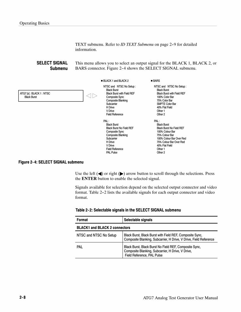
Operating Basics
2- 8 ATG7 Analog Test Generator User Manual
TEXT submenu. Refer to ID TEXT Submenu on page 2--9 for detailedinformation.
This menu allows you to select an output signal for the BLACK 1, BLACK 2, orBARS connector. Figure 2--4 shows the SELECT SIGNAL submenu.
ATG7 [x] : BLACK 1 : NTSCBlack Burst
NTSC and NTSC No Setup :Black BurstBlack Burst with Field REFComposite SyncComposite BlankingSubcarrierH DriveV DriveField Reference
PAL :Black BurstBlack Burst No Field REFComposite SyncComposite BlankingSubcarrierH DriveV DriveField ReferencePAL Pulse
NTSC and NTSC No Setup :Black BurstBlack Burst with Field REF100% Color Bar75% Color BarSMPTE Color Bar40% Flat FieldOther 1Other 2
PAL :Black BurstBlack Burst No Field REF100% Colour Bar75% Colour Bar100% Colour Bar Over Red75% Colour Bar Over Red40% Flat FieldOther 1Other 2
H BLACK 1 and BLACK 2 H BARS
Figure 2- 4: SELECT SIGNAL submenu
Use the left (A) or right (") arrow button to scroll through the selections. Pressthe ENTER button to enable the selected signal.
Signals available for selection depend on the selected output connector and videoformat. Table 2--2 lists the available signals for each output connector and videoformat.
Table 2- 2: Selectable signals in the SELECT SIGNAL submenu
Format Selectable signals
BLACK1 and BLACK 2 connectors
NTSC and NTSC No Setup Black Burst, Black Burst with Field REF, Composite Sync,Composite Blanking, Subcarrier, H Drive, V Drive, Field Reference
PAL Black Burst, Black Burst No Field REF, Composite Sync,Composite Blanking, Subcarrier, H Drive, V Drive,Field Reference, PAL Pulse
SELECT SIGNALSubmenu

Operating Basics
ATG7 Analog Test Generator User Manual 2- 9
Table 2- 2: Selectable signals in the SELECT SIGNAL submenu (Cont.)
Format Selectable signals
BARS connector
NTSC and NTSC No Setup Black Burst, Black Burst with Field REF, 100% Color Bar,75% Color Bar, SMPTE Color Bar, 40% Flat Field,Other 1 (SNG Color Bars), Other 2 (Monitor Setup Matrix)
PAL Black Burst, Black Burst No Field REF, 100% Colour Bar,75% Colour Bar, 100% Colour Bar Over Red,75% Colour Bar Over Red, 40% Flat Field,Other 1 (4 Level Pedestal & Pluge), Other 2 (Monitor Setup Matrix)
This menu allows you to edit text that is overlaid on the signal for the SIGNALand BARS outputs, and to set the display position of the text. Use the up (Y) ordown (B) arrow button to scroll through the menu. Figure 2--5 shows the IDTEXT submenu.
ATG7 [x] : ID TEXTStatus : Enable
Edit text
ATG7 [x] : ID TEXTX Position : 0.0 % APH
ATG7 [x] : ID TEXT : EDIT_
Set the horizontal position
Set the vertical positionATG7 [x] : ID TEXTY Position : 0.0 % APH
EnableBlink FastBlink SlowDisable
ATG7 [x] : ID TEXT : SAVE ENTERSave the text to the signal file
Select ID Text in the main menu orSELECT OUTPUT submenu
ENTER
Figure 2- 5: ID TEXT submenu
ID TEXT Submenu

Operating Basics
2- 10 ATG7 Analog Test Generator User Manual
H Status : Sets the display status of the text overlay. Use the left (A) or right(") arrow button to select Enable, Blink Fast (blinks approximately at0.5 second intervals), Blink Slow (blinks approximately at 1.0 secondinterval), or Disable. Press the ENTER button to confirm the selection.
H X Position: Sets the horizontal position of the text. The position is set as apercentage of active picture width. Use the left (A) or right (") arrow buttonto change the position. You can set the value from 0.0 % to 100.0 % in 1%steps.
H Y Position: Sets the vertical position of the text. The position is set as apercentage of active picture height. Use the left (A) or right (") arrowbutton to change the position. You can set the value from 0.0 % to 100.0 %in 1% steps.
H EDIT: Edits the text you want to display on the output test signal.
To edit the text, first press the ENTER button to enable the text edit mode.Use the left (A) or right (") arrow button to move the underscore character( _ ) to the character you want to change, and then use the up (Y) or down(B) arrow button to select the desired character. When you have entered allthe desired characters, press the ENTER button to end the text editingprocess. You can use up to 18 characters for the text. Use the blank characterto erase an unneeded character(s).
H SAVE: Saves the text and its position to the signal file currently beingoutput. Press the ENTER button to save them to the signal file.
This menu allows you to adjust the timing offset of the selected output relative tothe internal reference signal (frame reset signal). Use the up (Y) or down (B)arrow button to scroll through the menu. Figure 2--6 shows the TIMINGsubmenu.
TIMING Submenu

Operating Basics
ATG7 Analog Test Generator User Manual 2- 11
ATG7 [x] : TIMING : NTSCVertical : 0 Line (s)
ATG7 [x] : TIMING : NTSCHorizontal : 0.0000 msec
Set the vertical timing
Select TIMING in the main menu orSELECT OUTPUT submenu
Set the horizontal timing
Figure 2- 6: TIMING submenu
H Vertical : Sets the vertical timing offset. Use the left (A) or right (") arrowbutton to change the timing offset. You can set the value from --1/2 colorframe to +1/2 color frame in 1 line steps.
H Horizontal : Sets the horizontal timing offset. Use the left (A) or right (")arrow button to adjust the timing offset. You can set the value from --1 line to+1 line in one clock steps (18.5 ns).
NOTE. You can reset the timing offset to zero by pressing the left (A) and right(") arrow buttons simultaneously.
The ATG7 horizontal timing can only be adjusted in clock cycle increments. Youcan match the AGL7 timing to the ATG7 by adjusting the AGL7 fine timingcontrols.
This menu allows you to set the APL and Bounce features for the test signaloutput from the SIGNAL connector. Use the up (Y) or down (B) arrow buttonto scroll through the menu. Figure 2--7 shows the APL submenu.
APL Submenu

Operating Basics
2- 12 ATG7 Analog Test Generator User Manual
ATG7 [x] : APL : MODEAPL OFF
ATG7 [x] : APL : PERIOD1.0 sec
APL OFFHigh APLLow APLAPL (Bounce)Bounce
Select APL in the main menu
Set the bounce period
Figure 2- 7: APL submenu
H MODE : Sets the output mode of the APL signal. Use the left (A) or right(") arrow button to select the mode. The choices are:
H APL OFF : Outputs the selected signal without making any changes.
H High APL : Divides the video lines of the selected signal into 5 lines(for NTSC) or 4 lines (for PAL) and changes the lines except the last lineto the 100 % flat field signal, and then outputs them.
H Low APL : Divides the video lines of the selected signal into 5 lines (forNTSC) or 4 lines (for PAL) and changes the lines except the last line tothe 0 % flat field signal, and then outputs them.
H APL (Bounce) : Outputs the High APL signal and Low APL signalalternately for the period set in the PERIOD menu item.
H Bounce : Outputs the 100 % flat field signal and 0% flat field signalalternately (regardless of the selected signal) for the period set in thePERIOD menu item.
Press the ENTER button to confirm the selection.
H PERIOD : Sets the time interval between two signals when they are outputin APL (Bounce) or Bounce mode. Use the left (A) or right (") arrowbutton to change the interval. You can set the value from 0.5 seconds to2.0 seconds in 0.5 second steps.

Operating Basics
ATG7 Analog Test Generator User Manual 2- 13
Rear-Panel ConnectorsThe ATG7 Generator module is equipped with four BNC connectors: BLACK 1,BLACK 2, SIGNAL, and BARS. Figure 2--8 shows the ATG7 Generator modulerear-panel connectors.
Figure 2- 8: ATG7 module rear-panel connectors
H BLACK 1 : Outputs the black burst signals, timing pulse signals, andsubcarrier signal.
H BLACK 2 : Outputs the black burst signals, timing pulse signals, andsubcarrier signal.
H SIGNAL : Outputs the signals assigned to the front-panel test signalbuttons. Refer to Table 2--1 on page 2--3 about the signal sets available forthe connector.
H BARS : Outputs the black burst signals and color bars signals.
Factory Default SettingsTable 2--3 shows the factory default settings for the ATG7 Generator module.These settings are recalled when you select Factory Default from the PRESET: RECALL menu item in the mainframe main menu.
Table 2- 3: Factory default settingsMenu item name Settings
STATUS (Shows the signal format and signalname output from the SIGNAL connector)
NTSCSMPTE Color Bars
OUTPUT : BLACK 1 and BLACK 2
FORMAT NTSC
SIGNAL Black Burst

Operating Basics
2- 14 ATG7 Analog Test Generator User Manual
Table 2- 3: Factory default settings (Cont.)Menu item name Settings
OUTPUT : BARS
FORMAT NTSC
SIGNAL SMPTE Color Bar
ID TEXT
Status Disable
TIMING
Vertical 0 Line(s)
Horizontal 0.0000 msec
APL
Mode APL OFF
Period 1.0 sec

Reference


ATG7 Analog Test Generator User Manual 3- 1
Syntax
This section contains information on the Standard Commands for ProgrammableInstruments (SCPI) and the programming structure you can use to program yourATG7 Generator module.
Programming ModelSpecific conditions must exist before programming commands will affect the testsignal generated by a module.
Select the module using the :INSTrument:SELect command before executingany commands. Many of the commands used by the ATG7 module are shared byseveral modules and will be accepted without a reported error.
Many commands will accept either string or numeric arguments. For example: aboolean argument can either be “1” or “ON“.
Signal parameter commands that have a :STEP node can accept either a numericvalue or they can accept a string argument that refers to the :STEP increment.
Signal parameter commands with a :STEP node will accept the following stringsin addition to a numeric value:
UP.Use this argument to increase the parameter value one increment as definedby the :STEP value.
DOWN.Use this argument to decrease the parameter value one increment asdefined by the :STEP value.
MINimum.Use this argument to set the parameter value to the minimumacceptable value.
MAXimum.Use this argument to set the parameter value to the maximumacceptable value.
DEFault.Use this argument to set the parameter value to the default value.
Selecting the Module
Command Arguments

Syntax
3- 2 ATG7 Analog Test Generator User Manual
If you send a query with no argument, the response is the current value.You can also use MINimum, MAXimum, and DEFault as arguments for querieswhose command form can use these arguments (refer to the command syntax forthe specific command). Instead of returning the current value, queries using thesearguments return the following information:
MINimum. Return the minimum acceptable value.
MAXimum. Return the maximum acceptable value.
DEFault. Return the default value.
The following example demonstrates the effect of each of the arguments whenused with a step value.
1. :INSTrument:SELect "HDVG7:#" selects the digital video generator modulelocated in the slot number indicated by the “#” symbol.
2. :OUTPut:CIRCle:STATe ON displays a circle on the video display.
NOTE. :OUTPut:CIRCle:DIAMeter uses an argument that is the percent ofpicture height.
3. :OUTPut:CIRCle:DIAMeter DEFault sets the circle diameter to 90 percentof the screen height.
4. :OUTPut:CIRCle:DIAMeter:STEP 10 sets the step increment to 10 percent.
5. :OUTPut:CIRCle:DIAMeter DOWN changes the circle diameter to 80 percentof the screen height.
6. :OUTPut:CIRCle:DIAMeter 50 changes the circle diameter to 50 percent ofthe screen height.
7. :OUTPut:CIRCle:DIAMeter MAXimum changes the circle diameter to100 percent of the screen height.
8. :OUTPut:CIRCle:DIAMeter MINimum changes the circle diameter to0 percent of the screen height.
9. :OUTPut:CIRCle:DIAMeter UP changes the circle diameter to 10 percent ofthe screen height.
10. :OUTPut:CIRCle:DIAMeter? MAXimum queries the maximum circlediameter (not the current diameter). The query returns the value of 100percent, which is the maximum circle diameter allowable.
Query Arguments
Argument Example

Syntax
ATG7 Analog Test Generator User Manual 3- 3
SCPI Commands and QueriesSCPI is a standard created by a consortium that provides guidelines for remoteprogramming of instruments. These guidelines provide a consistent program-ming environment for instrument control and data transfer. This environmentuses defined programming messages, instrument responses, and data formatacross all SCPI instruments, regardless of manufacturer. The ATG7 Generatormodule uses a command language based on the SCPI standard.
The SCPI language is based on a hierarchical or tree structure (see Figure 3--1)that represents a subsystem. The top level of the tree is the root node; it isfollowed by one or more lower-level nodes.
DIAMeter
OUTPut
CIRCle
POSitionSTATe
Root node
Lower-levelnodes
Figure 3- 1: Example of SCPI subsystem hierarchy
You can create commands and queries from these subsystem hierarchy trees.Commands specify actions for the instrument to perform. Queries returnmeasurement data and information about parameter settings.
For more information on SCPI commands and programming structure, refer tothe TG700 Signal Generator Platform User Manual.

Syntax
3- 4 ATG7 Analog Test Generator User Manual

ATG7 Analog Test Generator User Manual 3- 5
Remote Commands
This section describes the command sets used for the ATG7 Generator moduleremote operation. The commands for the module are divided into the followingthree groups:
H MASS MEMORY commands ( Refer to the TG700 TV Signal GeneratorPlatform User Manual)
H OUTPUT commands
H SENSE commands
MASS MEMORY CommandsTwo MASS MEMORY commands are listed here for your reference. You canuse these to load and query the output test signal. Detailed information for usingthese commands are located in the TG700 TV Signal Generator Platform UserManual.
:MMEMory:LOAD:SIGNal <module_name>,<signal_name>:MMEMory:LOAD:SIGNal <slot_number>,<signal_name>
Loads a signal into the specified module.
:MMEMory:SIGNal:ACTive? <slot_number>|<module_name>
Returns the current output signal of the specified module.

Remote Commands
3- 6 ATG7 Analog Test Generator User Manual
OUTPUT CommandsUse these commands to control the output parameters of the module. Theseinclude ID text overlay and APL features.
:OUTPut<n>:STANdard NTSC|NTSC_NSU|PAL:SIGNal BB|BB_FREF|BB_NO_FREF|SYNC|BLANKING|
SUBCARRIER|H_DRIVE|V_DRIVE|FREF|PAL_PULSE (n=1,2)
BB|BB_NO_FREF|CB100_PER|CB75_PER|CB_SMPTE|FF40PER|CB100_OR|CB75_OR|OTHER_ONE|OTHER_TWO (n=4)
:OVERlay:BLINk:STATe ON|OFF:PERiod <numeric_value>
:TEXT:STATe ON|OFF:DATA <string>:POSition:HORizontal <numeric_value>:VERTical <numeric_value>
:SAVe:APL:MODe APL_OFF|APL_HIGH|APL_LOW|APL_BOUNCE:PERiod <numeric_value>
:OUTPut<n>:STANdard NTSC|NTSC_NSU|PAL
Sets the video standard for the BLACK 1, BLACK 2, or BARSoutput. The choices are NTSC, NTSC_NSU (NTSC no setup), orPAL. The <n> in the command represents the output connector typeand you can specify 1, 2, or 4. “1” represents the BLACK 1connector, “2” represents the BLACK 2 connector, and “4”represents the BARS connector.
Command Tree
Command Description

Remote Commands
ATG7 Analog Test Generator User Manual 3- 7
:OUTPut<n>:STANdard?
Returns the video standard for the BLACK 1, BLACK 2, or BARSoutput. The <n> in the command represents the output connector andyou can specify 1, 2, or 4. “1” represents the BLACK 1 connector,“2” represents the BLACK 2 connector, and “4” represents theBARS connector.
:OUTPut<n>:SIGNal BB|BB_FREF|BB_NO_FREF|SYNC|BLANKING|SUBCARRIER|H_DRIVE|V_DRIVE|FREF|PAL_PULSE (n=1,2)BB|BB_NO_FREF|CB100_PER|CB75_PER|CB_SMPTE|FF40PER|CB100_OR|CB75_OR|OTHER_ONE|OTHER_TWO (n=4)
Sets the signal available from the BLACK 1, BLACK 2, or BARSoutput. The <n> in the command represents the output connector andyou can specify 1, 2, or 4. “1” represents the BLACK 1 connector,“2” represents the BLACK 2 connector, and “4” represents theBARS connector.
If “1” or “2” is specified for the connector type, the choices are BB(black burst), BB_FREF (black burst with field reference),BB_NO_FREF (black burst no field reference), SYNC (compositesync), BLANKING (composite blanking), SUBCARRIER (subcarr-ier), H_DRIVE (H drive), V_DRIVE (V drive), FREF (Color FrameID), or PAL PULSE (PAL pulse).
If “4” is specified for the connector type, the choices are BB (blackburst), BB_FREF (black burst with field reference), BB_NO_FREF(black burst no field reference), CB100PER (100 % color (or colour)bars), CB75PER (75 % color (or colour) bars), CB_100_OR (100 %colour bars over red), CB_75_OR (75 % colour bars over red),CB_SMPTE (SMPTE color bars), FF40PER (40 % flat field),OTHER_ONE (Other 1), or OTHER_TWO (Other 2).
:OUTPut<n>:SIGNal?
Returns the current output signal for the BLACK 1, BLACK 2, orBARS output. The <n> in the command represents the outputconnector and you can specify 1, 2, or 4. “1” represents the BLACK1 connector, “2” represents the BLACK 2 connector, and “4”represents the BARS connector.
:OUTPut<n>:OVERlay:BLINk:STATe ON|OFF
Turns the text blinking mode on or off. You can also use 1 or 0instead of ON or OFF. The <n> in the command represents theoutput connector and you can specify 3 or 4. “3” represents theSIGNAL connector and “4” represents the BARS connector.

Remote Commands
3- 8 ATG7 Analog Test Generator User Manual
:OUTPut<n>:OVERlay:BLINk:STATe?
Returns the current state of the text blinking mode. The <n> in thecommand represents the output connector and you can specify 3 or4. “3” represents the SIGNAL connector and “4” represents theBARS connector.
:OUTPut<n>:OVERlay:BLINk:PERiod <numeric_value>
Sets the blinking interval of the text blinking mode. You can set thevalue as 0.5 seconds or 1.0 seconds. The <n> in the commandrepresents the output connector and you can specify 3 or 4. “3”represents the SIGNAL connector and “4” represents the BARSconnector.
:OUTPut<n>:OVERlay:BLINk:PERiod?
Returns the blinking interval of the text blinking mode. The <n> inthe command represents the output connector and you can specify 3or 4. “3” represents the SIGNAL connector and “4” represents theBARS connector.
:OUTPut<n>:TEXT:STATe ON|OFF
Turns the text overlay on the video signal on or off. You can also use1 or 0 instead of ON or OFF. The <n> in the command representsthe output connector and you can specify 3 or 4. “3” represents theSIGNAL connector and “4” represents the BARS connector.
:OUTPut<n>:TEXT:STATe?
Returns the current text overlay state. The <n> in the commandrepresents the output connector and you can specify 3 or 4. “3”represents the SIGNAL connector and “4” represents the BARSconnector.
:OUTPut<n>:TEXT:DATA <string>
Sets the current string for the text overlay mode. The <n> in thecommand represents the output connector and you can specify 3 or4. “3” represents the SIGNAL connector and “4” represents theBARS connector. The text string may contain up to 18 characters.
:OUTPut<n>:TEXT:DATA?
Returns the current string for the text overlay mode. The <n> in thecommand represents the output connector and you can specify 3 or4. “3” represents the SIGNAL connector and “4” represents theBARS connector.

Remote Commands
ATG7 Analog Test Generator User Manual 3- 9
:OUTPut<n>:TEXT:POSition:HORizontal <numeric_value>
Sets the text horizontal position in the video signal. The unit ispercent of active picture width. You can set the position from 0 % to100 % in 1 % steps. You can also use MIN, MAX, or DEF instead ofthe numeric value. The <n> in the command represents the outputconnector and you can specify 3 or 4. “3” represents the SIGNALconnector and “4” represents the BARS connector.
:OUTPut<n>:TEXT:POSition:HORizontal?
Returns the current text horizontal position in the video signal. The<n> in the command represents the output connector and you canspecify 3 or 4. “3” represents the SIGNAL connector and “4”represents the BARS connector.
:OUTPut<n>:TEXT:POSition:VERTical <numeric_value>
Sets the text vertical position in the video signal. The unit is percentof active picture height. You can set the position from 0 % to 100 %in 1 % steps. You can also use MIN, MAX, or DEF instead of thenumeric value. The <n> in the command represents the outputconnector and you can specify 3 or 4. “3” represents the SIGNALconnector and “4” represents the BARS connector.
:OUTPut<n>:TEXT:POSition:VERTical?
Returns the current text vertical position in the video signal. The<n> in the command represents the output connector and you canspecify 3 or 4. “3” represents the SIGNAL connector and “4”represents the BARS connector.
:OUTPut<n>:TEXT:SAVe
Saves the current text and its display position to the signal file.There are no arguments. The <n> in the command represents theoutput connector and you can specify 3 or 4. “3” represents theSIGNAL connector and “4” represents the BARS connector.
:OUTPut<n>:APL:MODe APL_OFF|APL_HIGH|APL_LOW|APL_BOUNCE|BOUNCE
Sets the output mode of the APL signal. Refer to Operating Basicsfor detailed information about the each mode. You can only specify“3” (SIGNAL connector) for the <n>.
:OUTPut<n>:APL:MODe?
Returns the current output mode of the APL signal. You can specifyonly “3” (SIGNAL connector) for the <n>.

Remote Commands
3- 10 ATG7 Analog Test Generator User Manual
:OUTPut<n>:APL:PERiod <numeric_value>
Sets the time interval between two signals when they are output inthe bounce modes. You can set the value from 0.5 seconds to2.0 seconds in 0.5 seconds steps. You can specify only “3” (SIGNALconnector) for the <n>.
:OUTPut<n>:APL:PERiod?
Returns the time interval between two signals when they are outputin the bounce modes. You can specify only “3” (SIGNAL connector)for the <n>.
SENSE CommandsUse these commands to adjust the timing offset of each output relative to theinternal reference signal (frame reset signal).
Refer to Operating Basics about the timing offset range.
:SENSe<n>:CORRection:MDELay:HORizontal <numeric_value>:STEP <numeric_value>
:VERTical <numeric_value>:STEP <numeric_value>
:SENSe<n>:CORRection:MDELay:HORizontal <numeric_value>
Sets the horizontal timing offset for the specified output. The timingresolution is clock-cycles. The unit is microseconds. You can useUP, DOWN, or DEF instead of the numeric values. If the argumentexceeds the horizontal time value, then the vertical offset is adjustedto accommodate the requested offset. The <n> in the commandrepresents the output connector and you can specify from 1 through4. “1” represents the BLACK 1 connector, “2” represents theBLACK 2 connector, “3” represents the SIGNAL connector, and “4”represents the BARS connector.
Command Tree
Command Description

Remote Commands
ATG7 Analog Test Generator User Manual 3- 11
:SENSe<n>:CORRection:MDELay:HORizontal?
Returns the horizontal timing offset of the specified output. The <n>in the command represents the output connector and you can specifyfrom 1 through 4. “1” represents the BLACK 1 connector, “2”represents the BLACK 2 connector, “3” represents the SIGNALconnector, and “4” represents the BARS connector.
:SENSe<n>:CORRection:MDELay:HORizontal:STEP <numeric_value>
Sets the step increment used by the UP or DOWN commands. Theunit is microseconds. You can use UP, DOWN, or DEF instead ofthe numeric values. The <n> in the command represents the outputconnector and you can specify from 1 through 4. “1” represents theBLACK 1 connector, “2” represents the BLACK 2 connector, “3”represents the SIGNAL connector, and “4” represents the BARSconnector.
:SENSe<n>:CORRection:MDELay:HORizontal:STEP?
Returns the step increment used by the UP or DOWN commands.The <n> in the command represents the output connector and youcan specify from 1 through 4. “1” represents the BLACK 1connector, “2” represents the BLACK 2 connector, “3” represents theSIGNAL connector, and “4” represents the BARS connector.
:SENSe<n>:CORRection:MDELay:VERTical <numeric_value>
Sets the vertical timing offset of the specified output. The argumentcan be a floating point value that is translated into integer lines witha horizontal offset. You can use UP, DOWN, or DEF instead of anumeric value. The <n> in the command represents the outputconnector and you can specify from 1 through 4. “1” represents theBLACK 1 connector, “2” represents the BLACK 2 connector, “3”represents the SIGNAL connector, and “4” represents the BARSconnector.
:SENSe<n>:CORRection:MDELay:VERTical?
Returns the vertical timing offset of the specified output. The <n> inthe command represents the output connector and you can specifyfrom 1 through 4. “1” represents the BLACK 1 connector, “2”represents the BLACK 2 connector, “3” represents the SIGNALconnector, and “4” represents the BARS connector.

Remote Commands
3- 12 ATG7 Analog Test Generator User Manual
:SENSe<n>:CORRection:MDELay:VERTical:STEP <numeric_value>
Sets the step increment used by the UP or DOWN commands. Youcan use MIN, MAX, or DEF instead of the numeric values. The <n>in the command represents the output connector and you can specifyfrom 1 through 4. “1” represents the BLACK 1 connector, “2”represents the BLACK 2 connector, “3” represents the SIGNALconnector, and “4” represents the BARS connector.
:SENSe<n>:CORRection:MDELay:VERTical:STEP?
Returns the step increment used by the UP or DOWN commands.The <n> in the command represents the output connector and youcan specify from 1 through 4. “1” represents the BLACK 1connector, “2” represents the BLACK 2 connector, “3” represents theSIGNAL connector, and “4” represents the BARS connector.

Appendices


ATG7 Analog Test Generator User Manual A- 1
Appendix A: Specifications
Tables A--1 through A--5 list the electrical characteristics and the environmentalcharacteristics of the ATG7 Generator module.
Electrical Characteristics
Table A- 1: Black burst and timing pulse outputs
Characteristic Performance requirements Reference information
Connector BNC
Number of outputs 2 BLACK 1 and BLACK 2
Output impedance, typical 75Ω
Black burst output signals
NTSC and NTSC No Setup Black BurstBlack Burst with Field REF
PAL Black BurstBlack Burst with No Field REF
Timing pulse output
Amplitude accuracy 1.00.1 VRise time
NTSC and NTSC No Setup 14020 nsPAL 25020 ns
Output signals
NTSC and NTSC No Setup Composite SyncComposite BlankingSubcarrierH DriveV DriveField Reference
PAL Composite SyncComposite BlankingSubcarrierH DriveV DriveField ReferencePAL Pulse

Appendix A: Specifications
A- 2 ATG7 Analog Test Generator User Manual
Table A- 2: Color bars signal output
Characteristic Performance requirements Reference information
Connector BNC
Number of outputs 1 BARS
Output impedance, typical 75Ω
Output signals
NTSC and NTSC No Setup SMPTE Color Bar100% Color Bar75% Color Bar40% Flat FieldBlack BurstBlack Burst with Field REFOther 1Other 2
PAL 100% Colour Bar75% Colour Bar100% Colour Bar Over Red75% Colour Bar Over Red40% Flat FieldBlack BurstBlack Burst No Field REFOther 1Other 2
ID text Maximum 18 characters
Luminance amplitude accuracy 1% Measured at 700 mV.
Chrominance to luminance gain 2% Chrominance is measured at red portion ofthe 75% Colour Bar Over Red signal.

Appendix A: Specifications
ATG7 Analog Test Generator User Manual A- 3
Table A- 3: Test signal output
Characteristic Performance requirements Reference information
Connector BNC
Number of outputs 1 SIGNAL
Output impedance, typical 75Ω
Output signals Refer to Table 2--1 on page 2--3 for detailedinformation about the output signals.
ID text Maximum 18 characters
Luminance amplitude accuracy 1% Measured at 700 mV.
Chrominance to luminance gain 1%Frequency response 1% To 5 MHz
Chrominance to luminance delay ≤10 ns Measured at 500 kHz and 4.43 MHz.
Linearity <1% <0.5 % (typical); measured at 5 stepsignal.
Differential gain error <0.5% Measured at modulated 5 step signal.
Differential phase error <0.5_ Measured at modulated 5 step signal.
Field tilt <0.5%Line tilt <0.5%
Table A- 4: Common outputs characteristics
Characteristic Performance requirements Reference information
Return loss ≥36 dB To 6 MHz
Burst amplitude accuracy 2%Sync amplitude accuracy 2%Blanking level 0 mV50 mVSCH phase accuracy 0_5_Timing offset
Range Full color frame
Resolution 54 MHz clock resolution ≃18.5 ns

Appendix A: Specifications
A- 4 ATG7 Analog Test Generator User Manual
Environmental Characteristics
Table A- 5: Environmental characteristics
Characteristic Description
Temperature
Operating 0 _C to +50 _C
Nonoperating --20 _C to +60 _C
Relative Humidity
Operating 20% to 80% (No condensation) ; Maximum wet-bulb temperature 29.4 _C
Nonoperating 5% to 90% (No condensation) ; Maximum wet-bulb temperature 40.0 _C
Altitude
Operating To 4.5 km (15,000 feet)Maximum operating temperature decreases 1 _C each 300 m above 1.5 km.
Nonoperating To 15 km (50,000 feet)
Vibration
Operating 3.04 m/s2 (0.31 Grms), 5 Hz to 500 Hz, 10 min, three axes
Nonoperating 23.3 m/s2 (2.38 Grms), 5 Hz to 500 Hz, 10 min, three axes
Shock
Nonoperating 294 m/s2 (30 G), half-sine, 11 ms duration

Index


ATG7 Analog Test Generator User Manual Index- 1
IndexAAccessoriesoptional, 1--2standard, 1--2
APL, 2--11APL submenu, 2--11ATG7 features, 1--1ATG7 module main menu, 2--5APL, 2--6ID TEXT, 2--6, 2--7SELECT OUTPUT, 2--6STATUS, 2--6TIMING, 2--6
BBARS connector, 2--13BLACK 1 connector, 2--13BLACK 2 connector, 2--13Bounce, 2--12
CCommandsRules for forming, 3--1Syntax, 3--1
EElectrical specifications, A--1Environmental specifications, A--4
FFactory default settings, 2--13Functional check, 1--3Functional command groups, 3--5
HHierarchy (SCPI), 3--3
IID TEXT submenu, 2--9
Installation, 1--2
MManuals, Related, iiiMASS MEMORY commands, 3--5
OOperating procedure, 2--1Option, 1--2Optional accessories, 1--2OUTPUT comands, 3--6
PProduct description, 1--1
RRear-panel connectors, 2--13Related Manuals, iiiRules, Command forming, 3--1
SSCPI, Subsystem hierarchy tree, 3--3SCPI commands and queries syntax, 3--3–3--4SELECT OUTPUT submenu, 2--7SELECT SIGNAL submenu, 2--8SENSE commands, 3--10SIGNAL connector, 2--13Signal set assigned to the test signal buttons, 2--3SpecificationsElectrical, A--1Environmental, A--4
Standard accessories, 1--2Syntax, Command, 3--1
TText overlay, 2--9TIMING submenu, 2--10

Index
Index- 2 ATG7 Analog Test Generator User Manual


User Manual
AVG7Analog Video Generator
www.tektronix.com

Copyright © Tektronix. All rights reserved. Licensed software products are owned by Tektronix or its suppliers and areprotected by United States copyright laws and international treaty provisions.
Tektronix products are covered by U.S. and foreign patents, issued and pending. Information in this publication supercedesthat in all previously published material. Specifications and price change privileges reserved.
TEKTRONIX and TEK are registered trademarks of Tektronix, Inc.
Contacting Tektronix
Tektronix, Inc.14200 SW Karl Braun DriveP.O. Box 500Beaverton, OR 97077USA
For product information, sales, service, and technical support:H In North America, call 1-800-833-9200.H Worldwide, visit www.tektronix.com to find contacts in your area.

AVG7 Analog Video Generator User Manual i
Table of Contents
Preface iii. . . . . . . . . . . . . . . . . . . . . . . . . . . . . . . . . . . . . . . . . . . . . . . . . . .About This Manual iii. . . . . . . . . . . . . . . . . . . . . . . . . . . . . . . . . . . . . . . . . . . . . . .Related Manuals iii. . . . . . . . . . . . . . . . . . . . . . . . . . . . . . . . . . . . . . . . . . . . . . . . .
Getting StartedProduct Description 1--1. . . . . . . . . . . . . . . . . . . . . . . . . . . . . . . . . . . . . . . . . . . . . .Accessories 1--2. . . . . . . . . . . . . . . . . . . . . . . . . . . . . . . . . . . . . . . . . . . . . . . . . . . . .Option 1--2. . . . . . . . . . . . . . . . . . . . . . . . . . . . . . . . . . . . . . . . . . . . . . . . . . . . . . . . .Installation 1--2. . . . . . . . . . . . . . . . . . . . . . . . . . . . . . . . . . . . . . . . . . . . . . . . . . . . .Functional Check 1--2. . . . . . . . . . . . . . . . . . . . . . . . . . . . . . . . . . . . . . . . . . . . . . . .
Operating BasicsOperating Procedure 2--1. . . . . . . . . . . . . . . . . . . . . . . . . . . . . . . . . . . . . . . . . . . . . .Selecting an Output Signal 2--2. . . . . . . . . . . . . . . . . . . . . . . . . . . . . . . . . . . . . . . . .AVG7 Module Main Menu 2--8. . . . . . . . . . . . . . . . . . . . . . . . . . . . . . . . . . . . . . . . .Rear-Panel Connectors 2--20. . . . . . . . . . . . . . . . . . . . . . . . . . . . . . . . . . . . . . . . . . . .Factory Default Settings 2--21. . . . . . . . . . . . . . . . . . . . . . . . . . . . . . . . . . . . . . . . . . .
ReferenceSyntax 3--1. . . . . . . . . . . . . . . . . . . . . . . . . . . . . . . . . . . . . . . . . . . . . . . . . . .Programming Model 3--1. . . . . . . . . . . . . . . . . . . . . . . . . . . . . . . . . . . . . . . . . . . . . .SCPI Commands and Queries 3--3. . . . . . . . . . . . . . . . . . . . . . . . . . . . . . . . . . . . . .
Remote Commands 3--5. . . . . . . . . . . . . . . . . . . . . . . . . . . . . . . . . . . . . . . .MASS MEMORY Commands 3--5. . . . . . . . . . . . . . . . . . . . . . . . . . . . . . . . . . . . . .OUTPUT Commands 3--6. . . . . . . . . . . . . . . . . . . . . . . . . . . . . . . . . . . . . . . . . . . . .SENSE Commands 3--12. . . . . . . . . . . . . . . . . . . . . . . . . . . . . . . . . . . . . . . . . . . . . . .
AppendicesAppendix A: Specifications A--1. . . . . . . . . . . . . . . . . . . . . . . . . . . . . . . . . .Electrical Characteristics A--1. . . . . . . . . . . . . . . . . . . . . . . . . . . . . . . . . . . . . . . . . .Environmental Characteristics A--3. . . . . . . . . . . . . . . . . . . . . . . . . . . . . . . . . . . . . .
Index

Table of Contents
ii AVG7 Analog Video Generator User Manual
List of Figures
Figure 2--1: Front-panel test signal buttons 2--3. . . . . . . . . . . . . . . . . . . .Figure 2--2: AVG7 module main menu 2--8. . . . . . . . . . . . . . . . . . . . . . . . .Figure 2--3: MOVING PICTURE submenu 2--10. . . . . . . . . . . . . . . . . . . .Figure 2--4: OVERLAY submenu 2--11. . . . . . . . . . . . . . . . . . . . . . . . . . . .Figure 2--5: LOGO submenu 2--12. . . . . . . . . . . . . . . . . . . . . . . . . . . . . . . .Figure 2--6: ID TEXT submenu 2--13. . . . . . . . . . . . . . . . . . . . . . . . . . . . . .Figure 2--7: CIRCLE submenu 2--14. . . . . . . . . . . . . . . . . . . . . . . . . . . . . .Figure 2--8: TIMING submenu 2--16. . . . . . . . . . . . . . . . . . . . . . . . . . . . . . .Figure 2--9: VIDEO submenu 2--17. . . . . . . . . . . . . . . . . . . . . . . . . . . . . . . .Figure 2--10: APL submenu 2--19. . . . . . . . . . . . . . . . . . . . . . . . . . . . . . . . .Figure 2--11: AVG7 module rear-panel connectors 2--20. . . . . . . . . . . . . . .Figure 3--1: Example of SCPI subsystem hierarchy 3--3. . . . . . . . . . . . . .
List of Tables
Table 1--1: Standard and optional accessories 1--2. . . . . . . . . . . . . . . . . .Table 2--1: Signal set assigned to the test signal buttons 2--3. . . . . . . . . .Table 2--2: Factory default settings 2--20. . . . . . . . . . . . . . . . . . . . . . . . . .Table A--1: Output channels A--1. . . . . . . . . . . . . . . . . . . . . . . . . . . . . . . .Table A--2: Common output characteristics A--1. . . . . . . . . . . . . . . . . . .Table A--3: Environmental characteristics A--3. . . . . . . . . . . . . . . . . . . . .

AVG7 Analog Video Generator User Manual iii
Preface
This manual documents the capabilities, operation, and specifications of theAVG7 Analog Video Generator module.
About This ManualThis manual is composed of the following sections:
H Getting Started contains product description and functional check procedure.
H Operating Basics explains how to operate the AVG7 module using themenus and front-panel buttons.
H Reference provides the syntax used in command descriptions and describesall programming commands.
H Appendices provides the specifications.
Related ManualsThe following documents are also available.
H The TG700 TV Signal Generator Platform Service Manual (Tektronix partnumber 070-A800-XX) describes how to maintain and service the mainframeand generator modules. This manual is an optional accessory.
H The TG700 TV Signal Generator Platform Module Installation Instructions(Tektronix part number 070-A824-XX) describes how to install and removethe modules, and how to upgrade the firmware of the mainframe.

Preface
iv AVG7 Analog Video Generator User Manual

Getting Started


AVG7 Analog Video Generator User Manual 1- 1
Getting Started
This section contains the following information:
H Product description
H Accessories
H Option
H Installation
H Functional check
Product DescriptionThe AVG7 Analog Video Generator module is designed to be installed in theTG700 TV Signal Generator Platform. The TG700 platform must be runningversion 3.1 or later firmware.
The module is an analog video signal generator which provides analog compos-ite and component video signals in various formats. The module contains thefollowing features:
H Supports the following system formats:
NTSC, NTSC no setup, PAL, 525 GBR, 525 YPbPr, 525 Beta, 625 GBR,625YPbPr
H Six analog composite or component video outputs
H Outputs a frame picture created by the Frame Picture Generator application(TG700 Option FP required)
H Overlay of circle, text, or logo on the video signal
H Generates a moving picture by scrolling the active picture area of the outputtest signal
H Full remote control using Ethernet interface

Getting Started
1- 2 AVG7 Analog Video Generator User Manual
AccessoriesTable 1--1 lists the standard and optional accessories provided with the AVG7Generator module.
Table 1- 1: Standard and optional accessories
Accessory Std. Opt.Tektronixpart number
TG700 TV Signal Generator Platform Module InstallationInstructions
D 070-A824-XX
TG700 Signal Generator Platform Software Library CD-ROM D 062-A249-XX
TG700 TV Signal Generator Platform Service Manual D 070-A800-XX
OptionThis subsection describes the option available for the AVG7 Generator module.The following option is available:
Option D1 (Test data report)
A calibration test data report will be provided with the AVG7 Generator modulewhen this option is specified.
InstallationRefer to the TG700 TV Signal Generator Platform Module InstallationInstructions for instructions on how to install the AVG7 Generator module.
Functional CheckThe following procedure determines whether the module is operating correctly.
The following equipment is required for the functional check:
H Waveform monitor
H 75 Ω BNC cable
Option D1 (Test DataReport)
Required equipment

Getting Started
AVG7 Analog Video Generator User Manual 1- 3
1. Install the module into the TG700 Platform mainframe using the installationprocedures described in the TG700 TV Signal Generator Platform UserManual.
2. Power on the TG700 TV Signal Generator Platform by connecting it to thepower source. The initialization of all the installed modules is executed.
3. Check that no error messages appear on the LCD display.
4. Warm up the instrument for 20 minutes.
5. Press the front-panelMODULE button until the AVG7 main menu shownbelow appears.
AVG7 [x] : STATUS : NTSCSMPTE Color Bars
6. Press the FORMAT button and use the left (A) or right (") arrow button toselect a format, then press the ENTER button.
7. Press one of the front-panel test signal buttons (for example COLOR BAR)to output a signal.
8. Press the CANCEL button to display the main menu.
9. Press the up (Y) or down (B) arrow button to select VIDEO from the mainmenu and then press the ENTER button. The VIDEO submenu shownbelow appears.
AVG7 [x] : VIDEO : CONFIGURATIONCH1/2/3: Composites
10. Press the left (A) or right (") arrow button to select CH1/2/3: Compositesand then press the ENTER button.
11. Connect the upper (or lower) CH 1 connector to the waveform monitor usingthe 75 Ω BNC cable.
12. Set the waveform monitor to view the signal.
13. Check that the signal appears as expected. For example, if you selected acolor bar signal in step 7, check that the color bar signal appears.
14. Disconnect the BNC cable from the CH 1 connector, and then connect theBNC cable to the CH 2 connector.
Procedure

Getting Started
1- 4 AVG7 Analog Video Generator User Manual
15. Check that the signal appears as expected.
16. Disconnect the BNC cable from the CH 2 connector, and then connect theBNC cable to the CH 3 connector.
17. Check that the signal appears as expected.
18. Disconnect the BNC cable from the CH 3 connector, and then connect theBNC cable to the CH 1 connector.
19. Press the test signal button again to output the another test signal in the samesignal set.
20. Check that the signal on the waveform monitor changes. You need notperform this check for the CH 2 and CH 3 connectors.
21. Repeat steps 11 through 20 for the lower (or upper) output channels.

Operating Basics


AVG7 Analog Video Generator User Manual 2- 1
Operating Basics
This section explains the operation of the AVG7 Generator module using thefront-panel buttons and menus. It also contains descriptions of the rear-panelconnectors.
Refer to the TG700 TV Signal Generator Platform User Manual for a detailedexplanation of the front-panel buttons and the LCD display.
Operating ProcedureAfter the module is installed in the mainframe, and the mainframe is installed inthe rack or other location where it will be used, access each function of themodule with the following procedure:
1. Connect the power connector on the rear panel to the AC electric powersource using the power cord.
Electric power is supplied to the mainframe.
2. Wait until the power up initialization process is complete, and check that noerror messages appear on the display.
3. Following the initialization process the mainframe main menu appears, asshown below.
TG700 : PRESET
4. Press the front-panelMODULE button until the AVG7 module main menuappears, as shown below.
AVG7 [x] : STATUS : NTSCSMPTE Color Bars
5. Select the signal format and the signal you want to output. Refer to Selectingan Output Signal on page 2--2 for more information.
6. Press the front-panel arrow buttons to select the desired main menu item orsubmenu item.
Refer to AVG7 Module Main Menu beginning on page 2--8 for detailedinformation about the main menu items and the submenu items.

Operating Basics
2- 2 AVG7 Analog Video Generator User Manual
Selecting an Output SignalWhen you output a signal from the AVG7 Generator module, you need to selecta signal format and output signal. This subsection provides instructions on howto output a signal.
If you press the front-panel FORMAT button when the AVG7 Generator moduleis selected (active), you can select the format for the output signals.
Perform the following steps to select the format:
1. Confirm that any menu item of the AVG7 module main menu is displayed. Ifthe menu is not displayed, press the front-panelMODULE button until theAVG7 module main menu appears, as shown below.
AVG7 [x] : STATUS : NTSCSMPTE Color Bars
2. Press the FORMAT button. The menu display changes as follows:
AVG7 [x] : SELECT FORMATNTSC (Current)
3. Press the left (A) or right (") arrow button to select one of the signalformats, and then press the ENTER button to confirm the selection.
NOTE. When you change signal format, synchronization shock occurs.
When you change the format while a signal is output, the instrument startsloading all of the signal set for the format and displays the message “NowLoading...”. When you see the message, “Done (Press CANCEL)”, pressthe CANCEL button.
All signal sets available in the module are already assigned to the correspondingtest signal buttons (see Figure 2--1). When you press any of the buttons, one ofthe signals in the signal set is output.
For example, when you press the COLOR BAR test signal button, you canoutput the 100% Color Bars signal in the Color Bars signal set.
Press the left (A) or right (") arrow button, or press the test signal buttonrepeatedly to select different signals assigned to the test signal button.
Selecting a Format
Selecting a Signal

Operating Basics
AVG7 Analog Video Generator User Manual 2- 3
Test signal buttons
Figure 2- 1: Front-panel test signal buttons
Table 2--1 lists the signal set assigned to each test signal button and the signalsthat can be selected in the signal set. The signals available in each signal set aredifferent from one signal format to another. The signals in the signal set can beadded or changed with improvement of the module.
Table 2- 1: Signal set assigned to the test signal buttons
Button name Signal set Signals in the signal set
NTSC/NTSC No Setup format
COLOR BAR Color Bars 100% Color Bars, 75% Color Bars,SMPTE Color Bars
LINEARITY Linearity 10 Step, 5 Step, Modulated 5 Step,Modulated Pedestal, Modulated Ramp,Shallow Ramp, Ramp
FLAT FIELD Flat Fields Black Burst, Black Burst with Field ref,0% Flat Field (NTSC only),10% Flat Field, 40 % Flat Field,50% Flat Field, 100% Flat Field,Field Square Wave
MULTI BURST Multi Burst 100% Multiburst, 60% Multiburst,Multipulse
SWEEP Sweep 60% Sweep, 100% Sweep,Chroma Frequency Response
MONITOR Monitor Convergence Pattern, Gray Window,100% Red Field, 2 Level Pedestal & Pluge,4 Level Pedestal & Pluge, 75% Red Field,Monitor Setup, White Window, Safe Area
PULSE BAR Pulse & Bar Window 2T Pulse & Bar, Sin X/X
TIMING ------ -- -- ----------
SDI ---- -- -- -- ----------
OTHER Other FCC Composite, FCC Multiburst,Matrix 1, NTSC Combination,NTC7 Composite, SNG Color Bars

Operating Basics
2- 4 AVG7 Analog Video Generator User Manual
Table 2- 1: Signal set assigned to the test signal buttons (Cont.)
Button name Signals in the signal setSignal set
PAL-1 format
COLOR BAR Color Bars 100% Colour Bars, 75% Colour Bars,100% Colour Bars Over Red,75% Colour Bars Over Red
LINEARITY Linearity 5 Step, Modulated 5 Step, Modulated Ramp,Ramp
FLAT FIELD Flat Fields Black Burst, 50% Flat Field, 100 % Flat Field,Field Square Wave
MULTI BURST Multi Burst 60% Multiburst, Multipulse
SWEEP Sweep 100% Sweep
MONITOR Monitor Convergence Pattern, Grey Window,White Window, 2 Level Pedestal & Pluge,4 Level Pedestal & Pluge, 75% Red Field
PULSE BAR Pulse & Bar Window 2T Pulse & Bar, Sin X/X
TIMING ------ -- -- ----------
SDI ---- -- -- -- ----------
OTHER Other CCIR 17, CCIR 18, CCIR 330, CCIR 331,UK ITS 1, UK ITS 2
PAL-2 format
COLOR BAR Color Bars 100% Colour Bars, 75% Colour Bars
LINEARITY Linearity 10 Step, 5 Step, Modulated 10 Step,Modulated 5 Step, Modulated Ramp,Shallow Ramp, Ramp, Modulated Pedestal
FLAT FIELD Flat Fields Black Burst, 50% Flat Field, 100 % Flat Field,Field Square Wave
MULTI BURST Multi Burst 100% Multiburst, 60% Multiburst
SWEEP Sweep 100% Sweep, 60% Sweep
MONITOR Monitor Convergence, Monitor Setup Matrix,100% Red Field, 75% Red Field,White Window, Safe Area
PULSE BAR Pulse & Bar 2T Pulse & Bar, Sin X/X
TIMING ------ -- -- ----------
SDI ---- -- -- -- ----------
OTHER Other ITS Matrix 1, UK 1 Line ITS

Operating Basics
AVG7 Analog Video Generator User Manual 2- 5
Table 2- 1: Signal set assigned to the test signal buttons (Cont.)
Button name Signals in the signal setSignal set
525 Beta format
COLOR BAR Color Bars 100% Color Bars, 75% Color Bars
LINEARITY Linearity 5 Step, Modulated Ramp, Ramp,Oversize Ramp, Shallow Ramp Matrix,Valid Ramp, Valid 5 Step
FLAT FIELD Flat Fields Black, 0% Flat Field, 100% Flat Field,50% Flat Field, Field Square Wave
MULTI BURST Multi Burst 60% Multiburst
SWEEP Sweep 60% Sweep
MONITOR Monitor Convergence Pattern, Grey Window,White Window, 2 Level Ped. & Pluge,4 Level Ped. & Pluge, 75% Red Field,Chroma Noise
PULSE BAR Pulse & Bar 2T Pulse & Bar, TPulses
TIMING Timing 50% Bowtie, 100% Bowtie
SDI ---- -- -- -- ----------
OTHER Other Test Matrix
525 GBR format
COLOR BAR Color Bars 100% Color Bars, 75% Color Bars
LINEARITY Linearity 5 Step, Shallow Ramp, Oversize Ramp,Shallow Ramp Matrix, Luminance Ramp
FLAT FIELD Flat Fields 0% Flat Field, 100% Flat Field,50% Flat Field, Field Square Wave
MULTI BURST Multi Burst 60% Multiburst
SWEEP Sweep 100% Line Sweep 5.5 MHz,100% Line Sweep 8 MHz
MONITOR Monitor Convergence Pattern, Grey Window,2 Level Ped. & Pluge, White Window,4 Level Ped. & Pluge
PULSE BAR Pulse & Bar 2T Pulse & Bar
TIMING Timing Bowtie
SDI ---- -- -- -- ----------
OTHER ------ -- -- ----------

Operating Basics
2- 6 AVG7 Analog Video Generator User Manual
Table 2- 1: Signal set assigned to the test signal buttons (Cont.)
Button name Signals in the signal setSignal set
525 YPbPr format
COLOR BAR Color Bars 100% Color Bars, 75% Color Bars
LINEARITY Linearity 5 Step, Ramp, Oversize Ramp,Shallow Ramp Matrix, Valid Ramp,Valid 5 Step, Modulated Ramp
FLAT FIELD Flat Fields Black, 0% Flat Field, 100% Flat Field,50% Flat Field, Field Square Wave
MULTI BURST Multi Burst 60% Multiburst
SWEEP Sweep 60% Sweep
MONITOR Monitor Convergence Pattern, Grey Window,White Window, 2 Level Ped. & Pluge,4 Level Ped. & Pluge, 75% Red Field,Chroma Noise
PULSE BAR Pulse & Bar 2T Pulse & Bar, T Pulses
TIMING Timing 50% Bowtie, 100% Bowtie
SDI ---- -- -- -- ----------
OTHER Other Test Matrix
625 YPbPr format
COLOR BAR Color Bars 100% Colour Bars, 75% Colour Bars,100% Colour Bars Over Red,75% Colour Bars Over Red
LINEARITY Linearity 5 Step, Modulated Ramp, Ramp,Oversize Ramp, Shallow Ramp Matrix,Valid 5 Step, Valid Ramp
FLAT FIELD Flat Fields 0% Flat Field, 100% Flat Field, 50 % Flat Field,Field Square Wave
MULTI BURST Multi Burst 60% Multiburst
SWEEP Sweep 60% Sweep
MONITOR Monitor Convergence Pattern, Grey Window,White Window, 2 Level Ped. & Pluge,4 Level Ped. & Pluge, 100% Red, 75% Red
PULSE BAR Pulse & Bar 2T Pulse & Bar, T Pulses
TIMING Timing 50% Bowtie, 100% Bowtie
SDI ---- -- -- -- ----------
OTHER Other Test Matrix

Operating Basics
AVG7 Analog Video Generator User Manual 2- 7
Table 2- 1: Signal set assigned to the test signal buttons (Cont.)
Button name Signals in the signal setSignal set
625 GBR format
COLOR BAR Color Bars 100% Colour Bars, 75% Colour Bars
LINEARITY Linearity Oversize Ramp, Luminance Ramp,Shallow Ramp, Shallow Ramp Matrix, 5 Step
FLAT FIELD Flat Fields 0% Flat Field, 50% Flat Field, 100% Flat Field,Field Square Wave
MULTI BURST Multi Burst 60% Multiburst
SWEEP Sweep 100% Sweep
MONITOR Monitor Convergence Pattern, Grey Window,2 Level Ped. & Pluge, White Window,4 Level Ped. & Pluge
PULSE BAR Pulse & Bar Window 2T Pulse & Bar
TIMING Timing Bowtie
SDI ---- -- -- -- ----------
OTHER ------ -- -- ----------
With the AVG7, you can download a frame picture file created by Frame PictureGenerator to the TG700 Option FP and output the picture. Refer to TG700 TVSignal Generator Platform User Manual for detailed information on how tocreate, download, and output a frame picture.

Operating Basics
2- 8 AVG7 Analog Video Generator User Manual
AVG7 Module Main MenuYou can set the logo, circle, text overlay, timing offset, and APL feature of thesignal outputs using the AVG7 module main menu.
Use the up (Y) or down (B) arrow button to scroll through the main menu.Figure 2--2 shows the AVG7 module main menu.
AVG7 [x] : STATUS : NTSCSMPTE Color Bars
AVG7 [x] : TIMING
Selection by the MODULE button
AVG7 [x] : MOVING PICTURE
AVG7 [x] : OVERLAY To OVERLAY submenu(page 2--11)
ENTER
CANCEL
To MOVING PICTURE submenu(page 2--10)
ENTER
CANCEL
To TIMING submenu(page 2--16)
ENTER
CANCEL
To VIDEO submenu(page 2--17)
ENTER
CANCEL
AVG7 [x] : VIDEO
To APL submenu(page 2--19)
ENTER
CANCEL
AVG7 [x] : APL
Figure 2- 2: AVG7 module main menu

Operating Basics
AVG7 Analog Video Generator User Manual 2- 9
MOVING PICTURE. Scrolls the active picture area of the output test signal. Whenyou select this menu item and then press the ENTER button, you will access theMOVING PICTURE submenu. Refer to MOVING PICTURE Submenu onpage 2--10 for detailed information.
OVERLAY. Selects an item (logo, text, or circle) that is overlaid on the output testsignal and sets the blinking mode for the overlay. When you select this menuitem and then press the ENTER button, you will access the OVERLAYsubmenu. Refer to OVERLAY Submenu on page 2--11 for detailed information.
TIMING. Sets the timing offset of the output signals relative to the internalreference signal (frame reset signal). When you select this menu item and thenpress the ENTER button, you will access the TIMING submenu. Refer toTIMING Submenu on page 2--16 for detailed information.
VIDEO. Sets the output channel configuration when a composite signal is beingoutput and enables or disables the signal output from CH 1, CH 2, and CH 3.When you select this menu item and then press the ENTER button, you willaccess the VIDEO submenu. Refer to VIDEO Submenu on page 2--17 for detailedinformation.
APL. Sets the APL and Bounce features available for the signal output. Whenyou select this menu item and then press the ENTER button, you will access theAPL submenu. Refer to APL Submenu on page 2--19 for detailed information.

Operating Basics
2- 10 AVG7 Analog Video Generator User Manual
This menu allows you to scroll the active picture area of the output signalup/down or left/right (or randomly). Use the up (Y) or down (B) arrow button toscroll the menu. Figure 2--3 shows the MOVING PICTURE submenu.
AVG7 [x] : MOVING PICTUREH Step : 0 Sample (s)
AVG7 [x] : MOVING PICTUREV Step : 0 Line (s)
AVG7 [x] : MOVING PICTUREPeriod : 1 Frame (s)
Select MOVING PICTUREin the main menu
AVG7 [x] : MOVING PICTURERandom : Disable
DisableEnable
Set the number of lines to be scrolled
Set the period, in frames, to be scrolled
Set the number of samples to be scrolled
Figure 2- 3: MOVING PICTURE submenu
H H Step: Sets the number of samples to be scrolled per frame set in thePeriod menu item. Use the left (A) or right (") arrow button to change thevalue. You can set the value from --60 to +60 in 4 samples steps.
H V Step: Sets the number of lines to be scrolled per frame set in the Periodmenu item. Use the left (A) or right (") arrow button to change the value.You can set the value from --15 to +15 in 1 line steps.
H Period: Sets the time interval between occurrences of the scrolling. Use theleft (A) or right (") arrow button to change the value. You can set the valuefrom 1 to 16 in 1 frame steps.
H Random: Sets whether or not the picture scrolls randomly. Use the left (A)or right (") arrow button to select between Disable and Enable. Press theENTER button to confirm the selection.
MOVING PICTURESubmenu

Operating Basics
AVG7 Analog Video Generator User Manual 2- 11
This menu allows you to select an item (logo, ID Text, or circle) to overlay onthe output test signal, and to set the blinking mode for the overlay. Use the up(Y) or down (B) arrow button to scroll through the menu. Figure 2--4 shows theOVERLAY submenu.
AVG7 [x] : OVERLAY : OBJECTLogo
Select OVERLAYin the main menu
AVG7 [x] : OVERLAY : BLINKOFF
OFFFastSlow
To LOGO submenu (page 2--12)To ID TEXT submenu (page 2--13)To CIRCLE submenu (page 2--15)
ENTER
CANCEL
LogoID TextCircle
Figure 2- 4: OVERLAY submenu
H OBJECT: Selects an item that is overlaid on the output test signal. Use theleft (A) or right (") arrow button to select Logo, ID Text, or Circle. Whenyou select any of these items and then press the ENTER button, you willaccess the submenu for setting that overlay. Refer to LOGO Submenu onpage 2--12, ID TEXT Submenu on page 2--13, or CIRCLE Submenu on page2--15 for detailed information.
H BLINK: Sets the blinking mode for the overlay. Use the left (A) or right(") arrow button to select OFF, Fast (blinks approximately at 0.5 secondinterval), or Slow (blinks approximately at 1.0 interval). Press the ENTERbutton to confirm the selection.
OVERLAY Submenu

Operating Basics
2- 12 AVG7 Analog Video Generator User Manual
This menu allows you to select a logo to overlay on the output test signal, and toset the display position of the logo. Use the up (Y) or down (B) arrow button toscroll through the menu. Figure 2--5 shows the LOGO submenu.
AVG7 [x] : OVERLAY : LOGOX Position : 0.0 % APH
Select OFF or a logo
AVG7 [x] : OVERLAY : LOGOY Position : 0.0 % APH
AVG7 [x] : OVERLAY : LOGOLogo : OFF
Select Logo in theOVERLAY submenu
Set the horizontal position
Set the vertical position
AVG7 [x] : OVERLAY : LOGO : SAVEPress ENTER to save parameters
ENTERSave the display position for the logo
Figure 2- 5: LOGO submenu
H X Position: Sets the horizontal position of the logo. The position is set as apercentage of active picture width. Use the left (A) or right (") arrow buttonto change the position. You can set the value from --100.0% to 0.0% in 0.1%steps.
H Y Position: Sets the vertical position of the logo. The position is set as apercentage of active picture height. Use the left (A) or right (") arrowbutton to change the position. You can set the value from --100.0% to 0.0%in 0.1% steps.
H Logo: Selects the logo you want to display. Use the left (A) or right (")arrow button to select OFF or a logo file name. Press the ENTER buttonconfirm the selection. When you select OFF, the logo overlay is disabled.
H SAVE: Saves the display position for the logo to the logo file. Press theENTER button to save the current settings.
LOGO Submenu

Operating Basics
AVG7 Analog Video Generator User Manual 2- 13
In order to display a logo using the LOGO submenu, you need to create the logofile (.lgo) and download it to the LOGO folder of the module.
Refer to the TG700 TV Signal Generator Platform User Manual for detailedinformation about how to create a logo file and download it to the TG700.
This menu allows you to edit text that is overlaid on the output test signal, and toset the display position of the text. Use the up (Y) or down (B) arrow button toscroll through the menu. Figure 2--6 shows the ID TEXT submenu.
AVG7 [x] : OVERLAY : TEXTStatus : Enable
Edit text
AVG7 [x] : OVERLAY : TEXTX Position : 10.0 % APH
AVG7 [x] : OVERLAY : TEXT : EDIT_
Set the horizontal position
Set the vertical positionAVG7 [x] : OVERLAY : TEXTY Position : 80.0 % APH
DisableEnable
AVG7 [x] : OVERLAY : TEXT : SAVE ENTERSave the text to the signal file
Select ID Text in theOVERLAY submenu
ENTER
Figure 2- 6: ID TEXT submenu
ID TEXT Submenu

Operating Basics
2- 14 AVG7 Analog Video Generator User Manual
H Status : Enables or disables the text overlay. Use the left (A) or right (")arrow button to select between Enable and Disable. Press the ENTERbutton to confirm the selection.
H X Position: Sets the horizontal position of the text. The position is set as apercentage of active picture width. Use the left (A) or right (") arrow buttonto change the position. You can set the value from 0.0% to 100.0% in1%steps.
H Y Position: Sets the vertical position of the text. The position is set as apercentage of active picture height. Use the left (A) or right (") arrowbutton to change the position. You can set the value from 0.0% to 100.0% in1% steps.
H EDIT: Edits the text you want to display on the output test signal.
To edit the text, first press the ENTER button to enable the text edit mode.Use the left (A) or right (") arrow button to move the underscore character( _ ) to the character you want to change, and then use the up (Y) or down(B) arrow button to select the desired character. When you enter all of thedesired characters then press the ENTER button to end the text editingprocess. You can use up to 30 characters for the text. Use the blank characterto erase an unneeded character(s).
H SAVE: Saves the text and its position to the signal file currently beingoutput. Press the ENTER button to save the text and its position to thesignal file.

Operating Basics
AVG7 Analog Video Generator User Manual 2- 15
This menu allows you to create a circle overlaid on the output test signal and setits position on the display. Use the up (Y) or down (B) arrow button to scrollthrough the menu. Figure 2--7 shows the CIRCLE submenu.
AVG7 [x] : OVERLAY : CIRCLEStatus : Enable
Set the diameter of the circle
AVG7 [x] : OVERLAY : CIRCLEX Position : 0.0 % APH
AVG7 [x] : OVERLAY : CIRCLEDiameter : 10.0 % APH
Set the horizontal position
Set the vertical positionAVG7 [x] : OVERLAY : CIRCLEY Position : 0.0 % APH
DisableEnable
Select Circle in theOVERLAY submenu
Figure 2- 7: CIRCLE submenu
H Status : Enables or disables the circle overlay. Use the left (A) or right (")arrow button to select between Enable and Disable. Press the ENTERbutton to confirm the selection.
H X Position: Sets the horizontal position of the circle. The position is set as apercentage of active picture width. Use the left (A) or right (") arrow buttonto change the position. You can set the value from --50.0% to 50.0% in 1%steps.
H Y Position: Sets the vertical position of the circle. The position is set as apercentage of active picture height. Use the left (A) or right (") arrowbutton to change the position. You can set the value from --50.0% to 50.0%in 1% steps.
H Diameter: Sets the diameter of the circle. The diameter is set as a percentageof active picture height. Use the left (A) or right (") arrow button to changethe value. You can set the value from 0.0% to 100.0% in 1% steps.
CIRCLE Submenu

Operating Basics
2- 16 AVG7 Analog Video Generator User Manual
This menu allows you to adjust the timing offset of the output signals relative tothe internal reference signal (frame reset signal). Use the up (Y) or down (B)arrow button to change the menu items. Figure 2--8 shows the TIMINGsubmenu.
AVG7 [x] : TIMING : NTSCHorizontal Coarse : 0.000 msec
AVG7 [x] : TIMING : NTSCHorizontal Fine : 0.00 nsec
Set the horizontal timing in 1 clock steps
Select TIMINGin the main menu
Set the horizontal timing in 0.1 ns steps
AVG7 [x] : TIMING : NTSCVertical : 0 Line (s)
Set the vertical timing in 1 line steps
Figure 2- 8: TIMING submenu
H Vertical: Sets the vertical timing offset. Use the left (A) or right (") arrowbutton to change the timing offset. You can set the value from --1 to +1 frameof the selected signal format in 1-line steps.
H Horizontal Coarse: Use the left (A) or right (") arrow button to adjust thecoarse horizontal offset. You can set the value from --1 to +1 line of theselected signal format in 1-clock (18.5 ns) steps.
H Horizontal Fine: Use the left (A) or right (") arrow button to adjust thefine horizontal offset. You can set the value from --10 ns to +10 ns in 0.1 nssteps.
NOTE. You can reset the timing offset to zero by pressing the left (A) and right(") arrow buttons simultaneously.
TIMING Submenu

Operating Basics
AVG7 Analog Video Generator User Manual 2- 17
This menu allows you to set the output channel configuration when a compositesignal is being output and to enable or disable the signal output of each channel.You can also set whether or not a sync signal is multiplexed with the B and Rsignal when a GBR signal is being output. Use the up (Y) or down (B) arrowbutton to scroll through the menu. Figure 2--9 shows the VIDEO submenu.
Select VIDEO in the main menu
AVG7 [x] : VIDEO : CONFIGURATIONCH1/2/3 Composites
AVG7 [x] : VIDEO : GBR SYNCSync ON All Channels
Sync ON GreenSync ON All Channels
AVG7 [x] : VIDEO : GON
ONOFF
CH1:Y CH2:C CH3:CompositeCH1/2/3 Composites
AVG7 [x] : VIDEO : BON
ONOFF
AVG7 [x] : VIDEO : RON
ONOFF
AVG7 [x] : VIDEO : SCH PHASE0 deg --180 deg to +180 deg
Figure 2- 9: VIDEO submenu
H CONFIGURATION: Sets the configuration of the output channels. Use theleft (A) or right (") arrow button to select between CH1:Y CH2:CCH3:Composite and CH1/2/3 Composites. When you select CH1:YCH2:C CH3:Composite, a Y signal, C signal, and composite signal areoutput from the CH 1, CH 2, and CH 3 connectors respectively. When youselect CH1/2/3:Composites, a composite signal is output from each outputconnector. Press the ENTER button to confirm the selection. This menuitem appears only when a composite signal is being output.
VIDEO Submenu

Operating Basics
2- 18 AVG7 Analog Video Generator User Manual
H GBR SYNC: Sets whether or not a sync signal is multiplexed with the Bsignal and R signal when a GBR signal is being output. Use the left (A) orright (") arrow button to select between Sync ON Green and Sync ON AllChannels. When you select Sync ON All Channels, a sync signal ismultiplexed with the G, B, and R signals. Press the ENTER button toconfirm the selection. This menu item appears only when a GBR signal isbeing output.
H G/Y: Turns the CH 1 signal output on or off for a component signal, or turnsthe Y signal on or off for a composite signal.. Use the left (A) or right (")arrow button to select between ON and OFF. Press the ENTER button toconfirm the selection. The signal name displayed depends on the videoformat of the currently selected signal (YPbPr component, GBR component,or composite) and the output channel configuration.
H B/Pb/B--Y: Turns the CH 2 signal output on or off for a component signal, orturns the B--Y signal on or off for a composite signal. Use the left (A) orright (") arrow button to select between ON and OFF. Press the ENTERbutton to confirm the selection. The signal name displayed depends on thevideo format of the currently selected signal (YPbPr component, GBRcomponent, or composite) and the output channel configuration.
H R/Pr/R--Y: Turns the CH 3 signal output on or off for a component signal, orturns the R--Y signal on or off for a composite signal. Use the left (A) orright (") arrow button to select between ON and OFF. Press the ENTERbutton to confirm the selection. The signal name displayed depends on thevideo format of the currently selected signal (YPbPr component, GBRcomponent, or composite) and the output channel configuration.
H SCH PHASE: Use the left (A) or right (") arrow button to adjust the SCHphase for a composite signal. You can set the value from --180 degrees (°) to+180 degrees (°) in 1 degree (°) steps. This setting is not saved a preset.
NOTE. If you try to set the SCH phase over +180 degrees, the value jumps to--179 degrees. Also, if you try to set the SCH phase under --180 degrees, thevalue jumps to +179 degrees.

Operating Basics
AVG7 Analog Video Generator User Manual 2- 19
This menu allows you to set the APL and Bounce features for the test signaloutputs. Use the up (Y) or down (B) arrow button to scroll through the menu.Figure 2--10 shows the APL submenu.
AVG7 [x] : APL : MODEAPL OFF
AVG7 [x] : APL : PERIOD1.0 sec
APL OFFHigh APLLow APLAPL (Bounce)Bounce
Select APL in the main menu
Set the bounce period
Figure 2- 10: APL submenu
H MODE : Sets the output mode of the APL signal. Use the left (A) or right(") arrow button to select the mode. The choices are:
H APL OFF : Outputs the selected signal without making any changes.
H High APL : Divides the video lines of the selected signal into 5 lines(for NTSC) or 4 lines (for PAL) and changes the lines except the last lineto the 100% flat field signal, and then outputs them.
H Low APL : Divides the video lines of the selected signal into 5 lines (forNTSC) or 4 lines (for PAL) and changes the lines except the last line tothe 0% flat field signal, and then outputs them.
H APL (Bounce) : Outputs the High APL signal and Low APL signalalternately for the period set in the PERIOD menu item.
H Bounce : Outputs the 100% flat field signal and 0% flat field signalalternately (regardless of the selected signal) for the period set in thePERIOD menu item.
Press the ENTER button to confirm the selection.
H PERIOD : Sets the time interval between two signals when they are outputin APL (Bounce) or Bounce mode. Use the left (A) or right (") arrowbutton to change the interval. You can set the value from 0.5 seconds to 2.0seconds in 0.5 second steps.
APL Submenu

Operating Basics
2- 20 AVG7 Analog Video Generator User Manual
Rear-Panel ConnectorsThe AVG7 Generator module is equipped with six connectors: one pair of CH 1,CH 2, and CH 3, which will output analog component or composite test signals.Figure 2--11 shows the AVG7 Generator module rear-panel connectors.
NOTE. Each pair of connectors (CH 1, CH 2, and CH 3) will both output thesame test signal.
Figure 2- 11: AVG7 module rear-panel connectors
H CH 1: Analog component or composite test signal output.
H CH 2: Analog component or composite test signal output.
H CH 3: Analog component or composite test signal output.

Operating Basics
AVG7 Analog Video Generator User Manual 2- 21
Factory Default SettingsTable 2--2 shows the factory default settings for the AVG7 Generator module.These settings are recalled when you select Factory Default from the PRESET: RECALL menu item in the mainframe main menu.
Table 2- 2: Factory default settingsMenu item name Settings
STATUS NTSCSMPTE Color Bars
MOVING PICTURE
H Step 0 Sample(s)
V Step 0 Line(s)
Period 1 Frame(s)
Random Disable
OVERLAY : OBJECT Logo
OVERLAY : BLINK OFF
OVERLAY : LOGO
Logo OFF
OVERLAY : ID TEXT
Status Disable
OVERLAY : CIRCLE
Status Disable
X Position 0.0% APH
Y Position 0.0% APH
Diameter 90% APH
TIMING
Vertical 0 Line(s)
Horizontal Coarse 0.0000 ms
Horizontal Fine 0.00 ns

Operating Basics
2- 22 AVG7 Analog Video Generator User Manual
Table 2- 2: Factory default settings (Cont.)Menu item name Settings
VIDEO
CONFIGURATION CH1/2/3 Composites
GBR SYNC Sync ON All Channels
G/Y ON
B/Pb/B--Y ON
R/Pr/R--Y ON
SCH PHASE 0 deg
APL
MODE APL OFF
PERIOD 1.0 s

Reference


AVG7 Analog Video Generator User Manual 3- 1
Syntax
This section contains information on the Standard Commands for ProgrammableInstruments (SCPI) and the programming structure you can use to program yourAVG7 Generator module.
Programming ModelSpecific conditions must exist before programming commands will affect the testsignal generated by a module.
Select the module using the :INSTrument:SELect command before executingany commands. Many of the commands used by the AVG7 module are shared byseveral modules and will be accepted without a reported error.
Many commands will accept either string or numeric arguments. For example: aboolean argument can either be “1” or “ON“.
Signal parameter commands that have a :STEP node can accept either a numericvalue or they can accept a string argument that refers to the :STEP increment.
Signal parameter commands with a :STEP node will accept the following stringsin addition to a numeric value:
UP.Use this argument to increase the parameter value one increment as definedby the :STEP value.
DOWN.Use this argument to decrease the parameter value one increment asdefined by the :STEP value.
MINimum.Use this argument to set the parameter value to the minimumacceptable value.
MAXimum.Use this argument to set the parameter value to the maximumacceptable value.
DEFault.Use this argument to set the parameter value to the default value.
Selecting the Module
Command Arguments

Syntax
3- 2 AVG7 Analog Video Generator User Manual
If you send a query with no argument, the response is the current value.You can also use MINimum, MAXimum, and DEFault as arguments for querieswhose command form can use these arguments (refer to the command syntax forthe specific command). Instead of returning the current value, queries using thesearguments return the following information:
MINimum. Return the minimum acceptable value.
MAXimum. Return the maximum acceptable value.
DEFault. Return the default value.
The following example demonstrates the effect of each of the arguments whenused with a step value.
1. :INSTrument:SELect "AVG7:#" selects the AVG7 Generator modulelocated in the slot number indicated by the “#” symbol.
2. :OUTPut:CIRCle:STATe ON displays a circle on the video display.
NOTE. :OUTPut:CIRCle:DIAMeter uses an argument that is the percent ofpicture height.
3. :OUTPut:CIRCle:DIAMeter DEFault sets the circle diameter to 90 percentof the screen height.
4. :OUTPut:CIRCle:DIAMeter:STEP 10 sets the step increment to 10 percent.
5. :OUTPut:CIRCle:DIAMeter DOWN changes the circle diameter to 80 percentof the screen height.
6. :OUTPut:CIRCle:DIAMeter 50 changes the circle diameter to 50 percent ofthe screen height.
7. :OUTPut:CIRCle:DIAMeter MAXimum changes the circle diameter to100 percent of the screen height.
8. :OUTPut:CIRCle:DIAMeter MINimum changes the circle diameter to0 percent of the screen height.
9. :OUTPut:CIRCle:DIAMeter UP changes the circle diameter to 10 percent ofthe screen height.
10. :OUTPut:CIRCle:DIAMeter? MAXimum queries the maximum circlediameter (not the current diameter). The query returns the value of 100percent, which is the maximum circle diameter allowable.
Query Arguments
Argument Example

Syntax
AVG7 Analog Video Generator User Manual 3- 3
SCPI Commands and QueriesSCPI is a standard created by a consortium that provides guidelines for remoteprogramming of instruments. These guidelines provide a consistent program-ming environment for instrument control and data transfer. This environmentuses defined programming messages, instrument responses, and data formatacross all SCPI instruments, regardless of manufacturer. The AVG7 Generatormodule uses a command language based on the SCPI standard.
The SCPI language is based on a hierarchical or tree structure (see Figure 3--1)that represents a subsystem. The top level of the tree is the root node; it isfollowed by one or more lower-level nodes.
DIAMeter
OUTPut
CIRCle
POSitionSTATe
Root node
Lower-levelnodes
Figure 3- 1: Example of SCPI subsystem hierarchy
You can create commands and queries from these subsystem hierarchy trees.Commands specify actions for the instrument to perform. Queries returnmeasurement data and information about parameter settings.
For more information on SCPI commands and programming structure, refer tothe TG700 Signal Generator Platform User Manual.

Syntax
3- 4 AVG7 Analog Video Generator User Manual

AVG7 Analog Video Generator User Manual 3- 5
Remote Commands
This section describes the remote commands used to control the AVG7 Generatormodule remotely. The commands to the module are divided into the followingthree groups:
H MASS MEMORY commands (Refer to the TG700 TV Signal GeneratorPlatform User Manual)
H OUTPUT commands
H SENSE commands
MASS MEMORY CommandsTwo MASS MEMORY commands are listed here for your reference. You canuse these to load and query the output test signal. Detailed information for usingthese commands are located in the TG700 TV Signal Generator Platform UserManual.
:MMEMory:LOAD:SIGNal <module_name>,<signal_name>:MMEMory:LOAD:SIGNal <slot_number>,<signal_name>
Loads a signal into the specified module.
:MMEMory:SIGNal:ACTive? <slot_number>|<module_name>
Returns the current output signal of the specified module.

Remote Commands
3- 6 AVG7 Analog Video Generator User Manual
OUTPUT CommandsUse these commands to control the output parameters of the module. Theseinclude output status and circle/text/logo overlay.
:OUTPut<n>:STATe ON|OFF:CIRCle:STATe ON|OFF:DIAMeter <numeric_value>:POSition:HORizontal <numeric_value>:VERTical <numeric_value>
:LOGO:STATe ON|OFF:POSition:HORizontal <numeric_value>:VERTical <numeric_value>
:SELect <logo_name>:SAVe
:TEXT:STATe ON|OFF:DATA <string>:POSition:HORizontal <numeric_value>:VERTical <numeric_value>
:SAVe:OVERlay:BLINk:STATe ON|OFF:PERiod <numeric_value>
:APL:MODe APL_OFF|APL_HIGH|APL_LOW|APL_BOUNCE:PERiod <numeric_value>
:MOVe:HORizontal <numeric_value>:VERTical <numeric_value>:PERiod <numeric_value>:RANDom[:STATe] ON|OFF
:VIDeo:CONFig YC|COMPOSITE:SCH <numeric_value>:SYNC:STATe ON|OFF
Command Tree
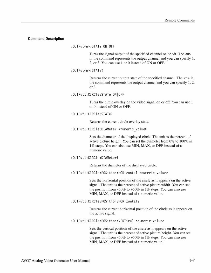
Remote Commands
AVG7 Analog Video Generator User Manual 3- 7
:OUTPut<n>:STATe ON|OFF
Turns the signal output of the specified channel on or off. The <n>in the command represents the output channel and you can specify 1,2, or 3. You can use 1 or 0 instead of ON or OFF.
:OUTPut<n>:STATe?
Returns the current output state of the specified channel. The <n> inthe command represents the output channel and you can specify 1, 2,or 3.
:OUTPut1:CIRCle:STATe ON|OFF
Turns the circle overlay on the video signal on or off. You can use 1or 0 instead of ON or OFF.
:OUTPut1:CIRCle:STATe?
Returns the current circle overlay state.
:OUTPut1:CIRCle:DIAMeter <numeric_value>
Sets the diameter of the displayed circle. The unit is the percent ofactive picture height. You can set the diameter from 0% to 100% in1% steps. You can also use MIN, MAX, or DEF instead of anumeric value.
:OUTPut1:CIRCle:DIAMeter?
Returns the diameter of the displayed circle.
:OUTPut1:CIRCle:POSition:HORizontal <numeric_value>
Sets the horizontal position of the circle as it appears on the activesignal. The unit is the percent of active picture width. You can setthe position from --50% to +50% in 1% steps. You can also useMIN, MAX, or DEF instead of a numeric value.
:OUTPut1:CIRCle:POSition:HORizontal?
Returns the current horizontal position of the circle as it appears onthe active signal.
:OUTPut1:CIRCle:POSition:VERTical <numeric_value>
Sets the vertical position of the circle as it appears on the activesignal. The unit is the percent of active picture height. You can setthe position from --50% to +50% in 1% steps. You can also useMIN, MAX, or DEF instead of a numeric value.
Command Description

Remote Commands
3- 8 AVG7 Analog Video Generator User Manual
:OUTPut1:CIRCle:POSition:VERTical?
Returns the current vertical position of the circle as it appears on theactive signal.
:OUTPut1:LOGO:STATe ON|OFF
Turns the logo overlay on the video signal on or off. You can use 1or 0 instead of ON or OFF.
:OUTPut1:LOGO:STATe?
Returns the current logo overlay state.
:OUTPut1:LOGO:POSition:HORizontal <numeric_value>
Sets the horizontal position of the logo as it appears on the activesignal. The unit is the percent of active picture width. You can setthe position from --100% to 0% in 0.1% steps. You can also useMIN, MAX, or DEF instead of a numeric value.
:OUTPut1:LOGO:POSition:HORizontal?
Returns the current horizontal position of the logo.
:OUTPut1:LOGO:POSition:VERTical <numeric_value>
Sets the vertical position of the logo as it appears on the activesignal. The unit is the percent of active picture height. You can setthe position from --100% to 0% in 0.1% steps. You can also useMIN, MAX, or DEF instead of a numeric value.
:OUTPut1:LOGO:POSition:VERTical?
Returns the current vertical position of the logo.
:OUTPut1:LOGO:SELect <logo_name>
Selects the logo used for the logo overlay.
:OUTPut1:LOGO:SELect?
Returns the current logo used for the logo overlay.
:OUTPut1:LOGO:SAVe
Saves the current display position of the logo to the logo file. Thereare no arguments.
:OUTPut1:TEXT:STATe ON|OFF
Turns the text overlay on the video signal on or off. You can use 1 or0 instead of ON or OFF.

Remote Commands
AVG7 Analog Video Generator User Manual 3- 9
:OUTPut1:TEXT:STATe?
Returns the current text overlay state.
:OUTPut1:TEXT:DATA <string>
Sets the current string for the text mode.
:OUTPut1:TEXT:DATA?
Returns the current string for the text mode.
:OUTPut1:TEXT:POSition:HORizontal <numeric_value>
Sets the text horizontal position in the video signal. The unit is thepercent of active picture width. You can set the position from 0% to100% in 1% steps. You can also use MIN, MAX, or DEF instead ofthe numeric value.
:OUTPut1:TEXT:POSition:HORizontal?
Returns the current text horizontal position in the video signal.
:OUTPut1:TEXT:POSition:VERTical <numeric_value>
Sets the text vertical position in the video signal. The unit is thepercent of active picture height. You can set the position from 0.0%to 100.0% in 1% steps. You can also use MIN, MAX, or DEFinstead of the numeric value.
:OUTPut1:TEXT:POSition:VERTical?
Returns the current text vertical position in the video signal.
:OUTPut1:TEXT:SAVe
Saves the current text and its display position to the signal file.There are no arguments.
:OUTPut1:OVERlay:BLINk:STATe ON|OFF
Turns on or off the blinking mode for the logo, text, and circleoverlay. You can also use 1 or 0 instead of ON or OFF
:OUTPut1:OVERlay:BLINk:STATe?
Returns the current state of the blinking mode for the logo, text, andcircle overlay.
:OUTPut1:OVERlay:BLINk:PERiod <numeric_value>
Sets the blinking interval of the blinking mode for the logo, text, andcircle overlay. You can set the value as 0.5 seconds or 1.0 seconds.

Remote Commands
3- 10 AVG7 Analog Video Generator User Manual
:OUTPut1:OVERlay:BLINk:PERiod?
Returns the blinking interval of the blinking mode for the logo, text,and circle overlay.
:OUTPut1:APL:MODe APL_OFF|APL_HIGH|APL_LOW|APL_BOUNCE|BOUNCE
Sets the output mode of the APL signal. Refer to APL Submenu onpage 2--19 for detailed information about the each mode.
:OUTPut1:APL:MODe?
Returns the current output mode of the APL signal.
:OUTPut1:APL:PERiod <numeric_value>
Sets the time interval between two signals when they are output inthe bounce modes. You can set the value from 0.5 seconds to 2.0seconds in 0.5 seconds steps.
:OUTPut1:APL:PERiod?
Returns the time interval between two signals when they are outputin the bounce modes.
:OUTPut1:MOVe:HORizontal <numeric_value>
Sets the amount of horizontal scrolling in the moving picture mode.You can set the value from --252 to +252 in 4 samples steps.
:OUTPut1:MOVe:HORizontal?
Returns the amount of horizontal scrolling in the moving picturemode.
:OUTPut1:MOVe:VERTical <numeric_value>
Sets the amount of vertical scrolling in the moving picture mode.You can set the value from --252 to +252 in 1 line steps.
:OUTPut1:MOVe:VERTical?
Returns the amount of vertical scrolling in the moving picture mode.
:OUTPut1:MOVe:PERiod <numeric_value>
Sets the time interval between occurrences of the scrolling. You canset the value from 1 to 16 in 1 field steps.
:OUTPut1:MOVe:PERiod?
Returns the time interval between occurrences of the scrolling.

Remote Commands
AVG7 Analog Video Generator User Manual 3- 11
:OUTPut1:MOVe:RANDom:STATe ON|OFF
Turns the random scrolling mode on or off. You can also use 1 or 0instead of ON or OFF.
:OUTPut1:MOVe:RANDom:STATe?
Returns the current state of the random scrolling mode.
:OUTPut1:VIDeo:CONFig YC|COMPOSITE
Sets the output channel configuration when a composite signal isbeing output. For YC, a Y signal, C signal, and composite signalwill be assigned to CH1, CH2, and CH3 respectively. For COM-POSITE, a composite signal will be assigned to all the threechannels.
:OUTPut1:VIDeo:CONFig?
Returns the current setting of the output channel configuration whena composite signal is being output.
:OUTPut1:VIDeo:SCH <numeric_value>
Sets the SCH phase for a composite signal. You can set the valuefrom --180 degrees to +180 degrees in 1 degree steps.
:OUTPut1:VIDeo:SCH?
Returns the current SCHphase setting.
:OUTPut1:VIDeo:SYNC:STATe ON|OFF
Sets whether or not a sync signal is multiplexed with the B and Rsignals when a GBR signal is being output. You can also use 1 or 0instead of ON or OFF.
:OUTPut1:VIDeo:SYNC:STATe?
Returns whether or not a sync signal is multiplexed with the B and Rsignals when a GBR signal is being output.

Remote Commands
3- 12 AVG7 Analog Video Generator User Manual
SENSE CommandsUse these commands to set the timing offset of the output signals relative to theinternal reference signal (frame reset signal).
Refer to Operating Basics for detailed information about the setting range.
:SENSe<n>:CORRection:MDELay:HORizontal <numeric_value>:STEP <numeric_value>
:VERTical <numeric_value>:STEP <numeric_value>
:SENSe1:CORRection:MDELay:HORizontal <numeric_value>
Sets the horizontal timing offset of the output signals. The timingresolution is clock-cycles. The units are microseconds. You can useUP, DOWN, or DEF instead of the numeric value. If the argumentexceeds the horizontal time value, then the vertical offset is adjustedto accommodate the requested delay.
:SENSe1:CORRection:MDELay:HORizontal?
Returns the current horizontal timing offset of the output signals.
:SENSe1:CORRection:MDELay:HORizontal:STEP <numeric_value>
Sets the step increment used by the UP or DOWN commands. Theunits are microseconds. You can use MIN, MAX, or DEF instead ofa numeric value.
:SENSe1:CORRection:MDELay:HORizontal:STEP?
Returns the current step increment.
:SENSe1:CORRection:MDELay:VERTical <numeric_value>
Sets the vertical timing offset of the output signals. The argumentcan be a floating point value that is translated into integer lines witha horizontal offset. You can use UP, DOWN, or DEF instead of anumeric value.
Command Tree
Command Description

Remote Commands
AVG7 Analog Video Generator User Manual 3- 13
:SENSe1:CORRection:MDELay:VERTical?
Returns the current vertical timing offset of the output signals.
:SENSe1:CORRection:MDELay:VERTical:STEP <numeric_value>
Sets the step increment used by the UP or DOWN commands. Youcan use MIN, MAX, or DEF instead of a numeric value.
:SENSe1:CORRection:MDELay:VERTical:STEP?
Returns the current step increment.

Remote Commands
3- 14 AVG7 Analog Video Generator User Manual

Appendices


AVG7 Analog Video Generator User Manual A- 1
Appendix A: Specifications
Tables A--1 through A--3 list the electrical and environmental characteristics ofthe AVG7 Generator module.
Electrical Characteristics
Table A- 1: Output channels
Characteristic Performance requirements Reference information
Channel 1 (CH 1)
Number of outputs 2
Output signals Y, G, or composite Each component of a composite signal canbe turned On or Off using the VIDEOsubmenu.
Channel 2 (CH 2)
Number of outputs 2
Output signals B--Y, Pb, B, C, or composite Each component of a composite signal canbe turned On or Off using the VIDEOsubmenu.
Channel 3 (CH 3)
Number of outputs 2
Output signals R--Y, Pr, R, or composite Each component of a composite signal canbe turned On or Off using the VIDEOsubmenu.
Table A- 2: Common output characteristics
Characteristic Performance requirements Reference information
Amplitude error
Absolute amplitude ≤1% Measured at 700 mV.
Channel gain matching ≤0.5% Measured at 700 mV, relative to CH 1.
Chrominance to luminance gain ≤1% Measured at 700 mV, relative to 500 kHz.

Appendix A: Specifications
A- 2 AVG7 Analog Video Generator User Manual
Table A- 2: Common output characteristics (cont.)
Characteristic Reference informationPerformance requirements
Delay error
Chrominance to luminance delay,typical
≤2.5 ns on a composite output.
Channel to channel delay ≤1 ns Relative to CH 1
Group delay, typical ≤5 ns to 5 MHzSCH Phase error, typical ≤1.25 ns (1.6_ at 3.58 MHz and2_ at
4.43 MHz)
Frequency response Flat within 0.5% peak from 0.5 MHz to5 MHz.
Typically≤5 % to 8 MHz at 700 mV,measured with a 1 m coax cable and peakdetector.
Line time distortion ≤0.5% Measured with FCC composite signal.
Field time distortion ≤0.5% Measured with field square wave.
K factor 2T5 pulse ≤0.5%Pulse/bar ratio, typical 1:1 within 0.5 % with 2T5 pulse and bar
signal.
DC offset ≤10 mVDifferential gain ≤0.5%Differential phase ≤0.5_Return loss ≥40 dB to 6 MHz

Appendix A: Specifications
AVG7 Analog Video Generator User Manual A- 3
Environmental Characteristics
Table A- 3: Environmental characteristics
Characteristic Description
Temperature
Operating 0 _C to +50 _C
Non-operating --20 _C to +60 _C
Relative Humidity
Operating 20% to 80% (No condensation); Maximum wet-bulb temperature 29.4 _C
Non-operating 5% to 90% (No condensation); Maximum wet-bulb temperature 40.0 _C
Altitude
Operating To 4.5 km (15 000 feet)Maximum operating temperature decreases 1 _C each 300 m above 1.5 km.
Non-operating To 15 km (50 000 feet)
Vibration
Operating 2.65 m/s2 (0.27 Grms), 5 Hz to 500 Hz, 10 min, three axes
Non-operating 22.36 m/s2 (2.28 Grms), 5 Hz to 500 Hz, 10 min, three axes
Shock
Non-operating 588 m/s2 (60 G), half-sine, 11 ms duration

Appendix A: Specifications
A- 4 AVG7 Analog Video Generator User Manual

Index


AVG7 Analog Video Generator User Manual Index- 1
IndexAAccessoriesoptional, 1--2standard, 1--2
Adjusting the SCH phase, 2--18APL, 2--19APL submenu, 2--19AVG7 features, 1--1AVG7 module main menu, 2--8APL, 2--9MOVING PICTURE, 2--9OVERLAY, 2--9TIMING, 2--9VIDEO, 2--9
BBounce, 2--19
CCH 1 connector, 2--20CH 2 connector, 2--20CH 3 connector, 2--20Circle overlay, 2--15CIRCLE submenu, 2--15CommandsRules for forming, 3--1Syntax, 3--1
EElectrical specifications, A--1Environmental specifications, A--3
FFactory default settings, 2--21functional check, 1--2
HHierarchy (SCPI), 3--3
IID TEXT submenu, 2--13Installation, 1--2
LLogo overlay, 2--12LOGO submenu, 2--12
MManuals, Related, iiiMASS MEMORY commands, 3--5MOVING PICTURE submenu, 2--10
OOperating procedure, 2--1Option, 1--2Optional accessories, 1--2OUTPUT commands, 3--6OVERLAY submenu, 2--11
PProduct description, 1--1
RRear-panel connectors, 2--20Related Manuals, iiiRemote commands, 3--5Rules, Command forming, 3--1
SSCPI, Subsystem hierarchy tree, 3--3SCPI commands and queries syntax, 3--3–3--4Signal set assigned to the test signal buttons, 2--3SpecificationsElectrical, A--1Environmental, A--3

Index
Index- 2 AVG7 Analog Video Generator User Manual
Standard accessories, 1--2Syntax, Command, 3--1
TText overlay, 2--13
TIMING submenu, 2--16
VVIDEO submenu, 2--17


User Manual
AWVG7Analog Wideband Video Generator
www.tektronix.com

Copyright © Tektronix. All rights reserved. Licensed software products are owned by Tektronix or its suppliers and areprotected by United States copyright laws and international treaty provisions.
Tektronix products are covered by U.S. and foreign patents, issued and pending. Information in this publication supercedesthat in all previously published material. Specifications and price change privileges reserved.
TEKTRONIX and TEK are registered trademarks of Tektronix, Inc.
Contacting Tektronix
Tektronix, Inc.14200 SW Karl Braun DriveP.O. Box 500Beaverton, OR 97077USA
For product information, sales, service, and technical support:H In North America, call 1-800-833-9200.H Worldwide, visit www.tektronix.com to find contacts in your area.

AWVG7 Analog Wideband Video Generator User Manual i
Table of Contents
Preface iii. . . . . . . . . . . . . . . . . . . . . . . . . . . . . . . . . . . . . . . . . . . . . . . . . . .About This Manual iii. . . . . . . . . . . . . . . . . . . . . . . . . . . . . . . . . . . . . . . . . . . . . . .Related Manuals iii. . . . . . . . . . . . . . . . . . . . . . . . . . . . . . . . . . . . . . . . . . . . . . . . .
Getting StartedProduct Description 1--1. . . . . . . . . . . . . . . . . . . . . . . . . . . . . . . . . . . . . . . . . . . . . .Accessories 1--2. . . . . . . . . . . . . . . . . . . . . . . . . . . . . . . . . . . . . . . . . . . . . . . . . . . . .Option 1--2. . . . . . . . . . . . . . . . . . . . . . . . . . . . . . . . . . . . . . . . . . . . . . . . . . . . . . . . .Installation 1--3. . . . . . . . . . . . . . . . . . . . . . . . . . . . . . . . . . . . . . . . . . . . . . . . . . . . .Functional Check 1--3. . . . . . . . . . . . . . . . . . . . . . . . . . . . . . . . . . . . . . . . . . . . . . . .
Operating BasicsOperating Procedure 2--1. . . . . . . . . . . . . . . . . . . . . . . . . . . . . . . . . . . . . . . . . . . . . .Selecting an Output Signal 2--2. . . . . . . . . . . . . . . . . . . . . . . . . . . . . . . . . . . . . . . . .AWVG7 Module Main Menu 2--4. . . . . . . . . . . . . . . . . . . . . . . . . . . . . . . . . . . . . . .Rear-Panel Connectors 2--15. . . . . . . . . . . . . . . . . . . . . . . . . . . . . . . . . . . . . . . . . . . .Factory Default Settings 2--16. . . . . . . . . . . . . . . . . . . . . . . . . . . . . . . . . . . . . . . . . . .
ReferenceSyntax 3--1. . . . . . . . . . . . . . . . . . . . . . . . . . . . . . . . . . . . . . . . . . . . . . . . . . .Programming Model 3--1. . . . . . . . . . . . . . . . . . . . . . . . . . . . . . . . . . . . . . . . . . . . . .SCPI Commands and Queries 3--3. . . . . . . . . . . . . . . . . . . . . . . . . . . . . . . . . . . . . .
Remote Commands 3--5. . . . . . . . . . . . . . . . . . . . . . . . . . . . . . . . . . . . . . . .MASS MEMORY Commands 3--5. . . . . . . . . . . . . . . . . . . . . . . . . . . . . . . . . . . . . .OUTPUT Commands 3--6. . . . . . . . . . . . . . . . . . . . . . . . . . . . . . . . . . . . . . . . . . . . .SENSE Commands 3--11. . . . . . . . . . . . . . . . . . . . . . . . . . . . . . . . . . . . . . . . . . . . . . .
AppendicesAppendix A: Specifications A--1. . . . . . . . . . . . . . . . . . . . . . . . . . . . . . . . . .Electrical Characteristics A--1. . . . . . . . . . . . . . . . . . . . . . . . . . . . . . . . . . . . . . . . . .Environmental Characteristics A--2. . . . . . . . . . . . . . . . . . . . . . . . . . . . . . . . . . . . . .
Index

Table of Contents
ii AWVG7 Analog Wideband Video Generator User Manual
List of Figures
Figure 2--1: Front-panel test signal buttons 2--3. . . . . . . . . . . . . . . . . . . .Figure 2--2: AWVG7 module main menu 2--4. . . . . . . . . . . . . . . . . . . . . .Figure 2--3: MOVING PICTURE submenu 2--6. . . . . . . . . . . . . . . . . . . .Figure 2--4: OVERLAY submenu 2--7. . . . . . . . . . . . . . . . . . . . . . . . . . . .Figure 2--5: LOGO submenu 2--8. . . . . . . . . . . . . . . . . . . . . . . . . . . . . . . .Figure 2--6: ID TEXT submenu 2--9. . . . . . . . . . . . . . . . . . . . . . . . . . . . . .Figure 2--7: CIRCLE submenu 2--11. . . . . . . . . . . . . . . . . . . . . . . . . . . . . .Figure 2--8: TIMING submenu 2--12. . . . . . . . . . . . . . . . . . . . . . . . . . . . . . .Figure 2--9: VIDEO submenu 2--14. . . . . . . . . . . . . . . . . . . . . . . . . . . . . . . .Figure 2--10: AWVG7 Generator module rear-panel connectors 2--15. . .Figure 3--1: Example of SCPI subsystem hierarchy 3--3. . . . . . . . . . . . . .
List of Tables
Table 1--1: Standard and optional accessories 1--2. . . . . . . . . . . . . . . . . .Table 2--1: Signal set assigned to the test signal buttons 2--3. . . . . . . . . .Table 2--2: Timing adjustment ranges for output signals 2--13. . . . . . . . .Table 2--3: Factory default settings 2--16. . . . . . . . . . . . . . . . . . . . . . . . . .Table A--1: Output channels A--1. . . . . . . . . . . . . . . . . . . . . . . . . . . . . . . .Table A--2: Common output characteristics A--1. . . . . . . . . . . . . . . . . . .Table A--3: Environmental characteristics A--2. . . . . . . . . . . . . . . . . . . . .

AWVG7 Analog Wideband Video Generator User Manual iii
Preface
This manual documents the capabilities, operation, and specifications of theAWVG7 Analog Wideband Video Generator module.
About This ManualThis manual is composed of the following sections:
H Getting Started contains product description and functional check proce-dures.
H Operating Basics explains how to operate the AWVG7 module using themenus and front-panel buttons.
H Reference provides the syntax used in command descriptions and describesall programming commands.
H Appendices provides the specifications.
Related ManualsThe following documents are also available.
H The TG700 TV Signal Generator Platform Service Manual (Tektronix partnumber 070-A800-XX) describes how to maintain and service the mainframeand generator modules. This manual is an optional accessory.
H The TG700 TV Signal Generator Platform Module Installation Instructions(Tektronix part number 070-A824-XX) describes how to install and removethe modules, and how to upgrade the firmware of the mainframe.

Preface
iv AWVG7 Analog Wideband Video Generator User Manual

Getting Started


AWVG7 Analog Wideband Video Generator User Manual 1- 1
Getting Started
This section contains the following information:
H Product description
H Accessories
H Option
H Installation
H Functional check
Product DescriptionThe AWVG7 Analog Wideband Video Generator module is designed to beinstalled in the TG700 TV Signal Generator Platform. The TG700 platform mustbe running version 3.1 or later firmware.
The module is a 30 MHz bandwidth video signal generator which provideswideband analog component video signals for HDTV system. The modulecontains the following features:
H Supports the following system formats:
1080/60i, 1080/59.94i, 1080/50i, 1080/24sF, 1080/23.98sF, 1080/30p,1080/29.97p, 1080/25p, 1080/24p, 1080/23.98p, 720/60p, 720/59.94p,720/50p, 720/24p, and 720/23.98p
H Six analog component video outputs
H Outputs a frame picture created by the Frame Picture Generator application(TG700 Option FP required)
H Overlay of circle, text, or logo on the video signal
H Generates a moving picture by scrolling the active picture area of the outputtest signal
H Full remote control using Ethernet interface

Getting Started
1- 2 AWVG7 Analog Wideband Video Generator User Manual
The signals of the following system formats are pre-installed in the mainframe:
1080/60i, 1080/59.94i, 1080/24sF, 1080/23.98sF, 720/60p, 720/59.94p
The signals other than above are included in the supplied CD-ROM, and you canoutput the signals by downloading them to the mainframe. Refer to the TG700TV Signal Generator Platform User Manual for detailed information on how todownload a signal file.
AccessoriesTable 1--1 lists the standard and optional accessories provided with the AWVG7Generator module.
Table 1- 1: Standard and optional accessories
Accessory Std. Opt.Tektronixpart number
TG700 TV Signal Generator Platform Module InstallationInstructions
D 070-A824-XX
TG700 Signal Generator Platform Software Library CD-ROM D 062-A249-XX
TG700 TV Signal Generator Platform Service Manual D 070-A800-XX
OptionThis subsection describes the option available for the AWVG7 Generatormodule. The following option is available:
Option D1 (Test data report)
A calibration test data report will be provided with the AWVG7 Generatormodule when this option is specified.
Option D1 (Test DataReport)

Getting Started
AWVG7 Analog Wideband Video Generator User Manual 1- 3
InstallationRefer to the TG700 TV Signal Generator Platform Module InstallationInstructions for instructions on how to install the AWVG7 Generator module.
NOTE. If the firmware version of your TG700 mainframe is 2.1 or earlier, youneed to upgrade the firmware of the mainframe before using the AVG7 module.Refer to the TG700 TV Signal Generator Platform Module Installation Instruc-tions for the procedures.
Functional CheckThe following procedure determines whether the module is operating correctly.
The following equipment is required for the functional check:
H HDTV waveform monitor
H Three 75 Ω BNC cables
H Three 75 Ω terminators
1. Install the module into the TG700 Platform mainframe using the installationprocedures described in the TG700 TV Signal Generator Platform UserManual.
2. Power on the TG700 TV Signal Generator Platform by connecting it to thepower source. The initialization of all the installed modules is executed.
3. Check that no error messages appear on the LCD display.
4. Warm up the instrument for 20 minutes.
5. Press the front-panelMODULE button until the AWVG7 main menu shownbelow appears.
AWVG7 [x] : STATUS : 1080 59i YPbPr100% Color Bars
6. Press the FORMAT button and use the left (A) or right (") arrow button toselect a format, then press the ENTER button.
Required equipment
Procedure

Getting Started
1- 4 AWVG7 Analog Wideband Video Generator User Manual
7. Press one of the front-panel test signal buttons (for example COLOR BAR)to output a signal.
8. Use the 75 Ω BNC cables to connect the upper (or lower) CH 1, CH 2, andCH 3 connectors to the CH A, CH B, and CH C inputs of the waveformmonitor respectively.
9. Use the 75 Ω terminators to terminate the other loop through connectors onthe waveform monitor real panel.
10. Press the CH A button on the waveform monitor, and set the waveformmonitor to view the signal.
11. Check that the signal appears as expected. For example, if you selected acolor bar signal in step 7, check that the color bar signal appears.
12. Press the CH B button on the waveform monitor.
13. Check that the signal appears as expected. For example, if you selected acolor bar signal in step 7, check that the color bar signal appears.
14. Press the CH C button on the waveform monitor.
15. Check that the signal appears as expected. For example, if you selected acolor bar signal in step 7, check that the color bar signal appears.
16. Press the CH A button on the waveform monitor.
17. Press the test signal button again to output another test signal in the samesignal set.
18. Check that the signal on the waveform monitor changes. You do not need toperform this check for the CH 2 and CH 3 connectors.
19. Disconnect the BNC cable from the upper (or lower) CH 1, CH 2, andCH 3 connectors, and then connect the BNC cables to the lower (or upper)CH 1, CH 2, and CH 3 connectors.
20. Repeat steps 10 through 18 for the lower (or upper) output channels.

Operating Basics


AWVG7 Analog Wideband Video Generator User Manual 2- 1
Operating Basics
This section explains the operation of the AWVG7 Generator module using thefront-panel buttons and menus. It also contains descriptions of the rear-panelconnectors.
Refer to the TG700 TV Signal Generator Platform User Manual for a detailedexplanation of the front-panel buttons and the LCD display.
Operating ProcedureAfter the module is installed in the mainframe, and the mainframe is installed inthe rack or other location where it will be used, access each function of themodule with the following procedure:
1. Connect the power connector on the rear panel to the AC electric powersource using the power cord.
Electric power is supplied to the mainframe.
2. Wait until the power up initialization process is complete, and check that noerror messages appear on the display.
3. Following the initialization process the mainframe main menu appears, asshown below.
TG700 : PRESET
4. Press the front-panelMODULE button until the AWVG7 module mainmenu appears, as shown below.
AWVG7 [x] : STATUS : 1080 59i YPbPr100% Color Bars
5. Select the signal format and the signal you want to output. Refer to Selectingan Output Signal on page 2--2 for more information.
6. Press the front-panel arrow buttons to select the desired main menu item orsubmenu item.
Refer to AWVG7 Module Main Menu beginning on page 2--4 for detailedinformation about the main menu items and the submenu items.

Operating Basics
2- 2 AWVG7 Analog Wideband Video Generator User Manual
Selecting an Output SignalWhen you output a signal from the AWVG7 Generator module, you need toselect a signal format and output signal. This subsection provides instructions onhow to output a signal.
If you press the front-panel FORMAT button when the AWVG7 Generatormodule is selected (active), you can select the format for the output signals.
Perform the following steps to select the format:
1. Confirm that any menu item of the AWVG7 module main menu is displayed.If the menu is not displayed, press the front-panelMODULE button untilthe AWVG7 module main menu appears, as shown below.
AWVG7 [x] : STATUS : 1080 59i YPbPr100% Color Bars
2. Press the FORMAT button. The menu display changes as follows:
AWVG7 [x] : SELECT FORMAT1080 59i (Current)
3. Press the left (A) or right (") arrow button to select one of the signalformats, and then press the ENTER button to confirm the selection.
NOTE. When you change the signal format, synchronization shock occurs.
When you change the format while a signal is being output, the instrumentstarts loading all of the signal set for the format and displays the message“Now Loading...”. When you see the message, “Done (Press CANCEL)”,press the CANCEL button.
All signal sets available in the module are already assigned to the correspondingtest signal buttons (see Figure 2--1 on page 2--3). When you press any of thebuttons, one of the signals in the signal set is output.
For example, when you press the COLOR BAR test signal button, you canoutput the 100% Color Bars signal in the Color Bars signal set.
Press the left (A) or right (") arrow button, or press the test signal buttonrepeatedly to select different signals assigned to the test signal button.
Selecting a Format
Selecting a Signal

Operating Basics
AWVG7 Analog Wideband Video Generator User Manual 2- 3
Test signal buttons
Figure 2- 1: Front-panel test signal buttons
Table 2--1 lists the signal set assigned to each test signal button and the signalsthat can be selected in the signal set. The signals in the signal set can be added orchanged with improvement of the module.
Table 2- 1: Signal set assigned to the test signal buttons
Button name Signal set Signals in the signal set
COLOR BAR Color Bars 100% Color Bars, 75% Color Bars
LINEARITY Linearity 10 Step, 5 Step, Ramp,Shallow Ramp, Valid Ramp *
FLAT FIELD Flat Fields 0% Flat Field, 100% Flat Field, 50% Flat Field
MULTI BURST Multi Burst Multiburst 1-10 MHz, Multiburst 10--20 MHz,Multiburst 20-30 MHz
SWEEP Sweep 100% Sweep 1-15 MHz,100% Sweep 1-30 MHz
MONITOR Monitor 75% Blue Field, Convergence,75% Green Field, 75% Red Field
PULSE BAR Pulse & Bar 2T30 Pulse & Bar
TIMING Timing Bowtie 1 ns Marker
SDI ---- -- -- -- ----------
OTHER ------ -- -- ----------
* YPbPr format only
With the AWVG7, you can download a frame picture file created by FramePicture Generator to the TG700 Option FP and output the picture. Refer toTG700 TV Signal Generator Platform User Manual for detailed information onhow to create, download, and output a frame picture.

Operating Basics
2- 4 AWVG7 Analog Wideband Video Generator User Manual
AWVG7 Module Main MenuYou can set the logo, circle, text overlay, and timing offset of the signal outputsby using the AWVG7 module main menu.
Use the up (Y) or down (B) arrow button to scroll through the main menu.Figure 2--2 shows the AWVG7 module main menu.
AWVG7 [x] : STATUS : 1080 59I YPbPr100% Color Bars
AWVG7 [x] : TIMING
Selection by the MODULE button
AWVG7 [x] : MOVING PICTURE
AWVG7 [x] : OVERLAY To OVERLAY submenu(page 2--7)
ENTER
CANCEL
To MOVING PICTURE submenu(page 2--6)
ENTER
CANCEL
To TIMING submenu(page 2--12)
ENTER
CANCEL
To VIDEO submenu(page 2--14)
ENTER
CANCEL
AWVG7 [x] : VIDEO
Figure 2- 2: AWVG7 module main menu

Operating Basics
AWVG7 Analog Wideband Video Generator User Manual 2- 5
MOVING PICTURE. Scrolls the active picture area of the output test signal. Whenyou select this menu item and then press the ENTER button, you will access theMOVING PICTURE submenu. Refer to MOVING PICTURE Submenu onpage 2--6 for detailed information.
OVERLAY. Selects an item (logo, text, or circle) that is overlaid on the output testsignal and sets the blinking mode for the overlay. When you select this menuitem and then press the ENTER button, you will access the OVERLAYsubmenu. Refer to OVERLAY Submenu on page 2--7 for detailed information.
TIMING. Sets the timing offset of the output signals relative to the internalreference signal (frame reset signal). When you select this menu item and thenpress the ENTER button, you will access the TIMING submenu. Refer toTIMING Submenu on page 2--12 for detailed information.
VIDEO. Sets whether or not a sync signal is multiplexed with the B and R signalwhen a GBR signal is being output and enables or disables the signal outputfrom CH 1, CH 2, and CH 3. When you select this menu item and then press theENTER button, you will access the VIDEO submenu. Refer to VIDEO Submenuon page 2--14 for detailed information.

Operating Basics
2- 6 AWVG7 Analog Wideband Video Generator User Manual
This menu allows you to scroll the active picture area of the output signalup/down or left/right (or randomly). Use the up (Y) or down (B) arrow button toscroll the menu. Figure 2--3 shows the MOVING PICTURE submenu.
AWVG7 [x] : MOVING PICTUREH Step : 0 Sample (s)
AWVG7 [x] : MOVING PICTUREV Step : 0 Line (s)
AWVG7 [x] : MOVING PICTUREPeriod : 1 Frame (s)
Select MOVING PICTUREin the main menu
AWVG7 [x] : MOVING PICTURERandom : Disable
DisableEnable
Set the number of lines to be scrolled
Set the period, in frames, to be scrolled
Set the number of samples to be scrolled
Figure 2- 3: MOVING PICTURE submenu
H H Step: Sets the number of samples to be scrolled per frame set in thePeriod menu item. Use the left (A) or right (") arrow button to change thevalue. You can set the value from --60 to +60 in 4 sampled steps.
H V Step: Sets the number of lines to be scrolled per frame set in the Periodmenu item. Use the left (A) or right (") arrow button to change the value.You can set the value from --15 to +15 in 1 line step.
H Period: Sets the time interval between occurrences of the scrolling. Use theleft (A) or right (") arrow button to change the value. You can set the valuefrom 1 to 16 in 1 frame step.
H Random: Sets whether or not the picture scrolls randomly. Use the left (A)or right (") arrow button to select between Disable and Enable. Press theENTER button to confirm the selection.
MOVING PICTURESubmenu

Operating Basics
AWVG7 Analog Wideband Video Generator User Manual 2- 7
This menu allows you to select an item (logo, ID Text, or circle) to overlay onthe output test signal, and to set the blinking mode for the overlay. Use the up(Y) or down (B) arrow button to scroll through the menu. Figure 2--4 shows theOVERLAY submenu.
AWVG7 [x] : OVERLAY : OBJECTLogo
Select OVERLAYin the main menu
AWVG7 [x] : OVERLAY : BLINKOFF
OFFFastSlow
To LOGO submenu (page 2--8)To ID TEXT submenu (page 2--9)To CIRCLE submenu (page 2--11)
ENTER
CANCEL
LogoID TextCircle
Figure 2- 4: OVERLAY submenu
H OBJECT: Selects an item that is overlaid on the output test signal. Use theleft (A) or right (") arrow button to select Logo, ID Text, or Circle. Whenyou select any of these items and then press the ENTER button, you willaccess the submenu for setting that overlay. Refer to LOGO Submenu onpage 2--8, ID TEXT Submenu on page 2--9, or CIRCLE Submenu onpage 2--11 for detailed information.
H BLINK: Sets the blinking mode for the overlay. Use the left (A) or right(") arrow button to select OFF, Fast (blinks at approximately 0.5 secondintervals), or Slow (blinks at approximately 1.0 intervals). Press the ENTERbutton to confirm the selection.
OVERLAY Submenu

Operating Basics
2- 8 AWVG7 Analog Wideband Video Generator User Manual
This menu allows you to select a logo to overlay on the output test signal, and toset the display position of the logo. Use the up (Y) or down (B) arrow button toscroll through the menu. Figure 2--5 shows the LOGO submenu.
AWVG7 [x] : OVERLAY : LOGOX Position : 0.0 % APH
Select OFF or a logo
AWVG7 [x] : OVERLAY : LOGOY Position : 0.0 % APH
AWVG7 [x] : OVERLAY : LOGOLogo : OFF
Select Logo in theOVERLAY submenu
Set the horizontal position
Set the vertical position
AWVG7 [x] : OVERLAY : LOGO : SAVEPress ENTER to save parameters
ENTERSave the display position for the logo
Figure 2- 5: LOGO submenu
H X Position: Sets the horizontal position of the logo. The position is set as apercentage of active picture width. Use the left (A) or right (") arrow buttonto change the position. You can set the value from --100.0% to 0.0% in 0.1%steps.
H Y Position: Sets the vertical position of the logo. The position is set as apercentage of active picture height. Use the left (A) or right (") arrowbutton to change the position. You can set the value from --100.0% to 0.0%in 0.1% steps.
H Logo: Selects the logo you want to display. Use the left (A) or right (")arrow button to select OFF or a logo file name. Press the ENTER button toconfirm the selection. When you select OFF, the logo overlay is disabled.
H SAVE: Saves the display position for the logo to the logo file. Press theENTER button to save the current settings.
LOGO Submenu

Operating Basics
AWVG7 Analog Wideband Video Generator User Manual 2- 9
In order to display a logo using the LOGO submenu, you need to create the logofile (.lgo) and download it to the LOGO folder of the module.
Refer to the TG700 TV Signal Generator Platform User Manual for detailedinformation about how to create a logo file and download it to the TG700.
This menu allows you to edit text that is overlaid on the output test signal, and toset the display position of the text. Use the up (Y) or down (B) arrow button toscroll through the menu. Figure 2--6 shows the ID TEXT submenu.
AWVG7 [x] : OVERLAY : TEXTStatus : Enable
Edit text
AWVG7 [x] : OVERLAY : TEXTX Position : 0.0 % APH
AWVG7 [x] : OVERLAY : TEXT : EDIT_
Set the horizontal position
Set the vertical positionAWVG7 [x] : OVERLAY : TEXTY Position : 0.0 % APH
DisableEnable
AWVG7 [x] : OVERLAY : TEXT : SAVE ENTERSave the text to the signal file
Select ID Text in theOVERLAY submenu
ENTER
Figure 2- 6: ID TEXT submenu
ID TEXT Submenu

Operating Basics
2- 10 AWVG7 Analog Wideband Video Generator User Manual
H Status : Enables or disables the text overlay. Use the left (A) or right (")arrow button to select between Enable and Disable. Press the ENTERbutton to confirm the selection.
H X Position: Sets the horizontal position of the text. The position is set as apercentage of active picture width. Use the left (A) or right (") arrow buttonto change the position. You can set the value from 0.0% to 100.0% in 1%steps.
H Y Position: Sets the vertical position of the text. The position is set as apercentage of active picture height. Use the left (A) or right (") arrowbutton to change the position. You can set the value from 0.0% to 100.0% in1% steps.
H EDIT: Edits the text you want to display on the output test signal.
To edit the text, first press the ENTER button to enable the text edit mode.Use the left (A) or right (") arrow button to move the underscore character( _ ) to the character you want to change, and then use the up (Y) or down(B) arrow button to select the desired character. When you enter all of thedesired characters then press the ENTER button to end the text editingprocess. You can use up to 30 characters for the text. Use the blank characterto erase any characters that are not needed.
H SAVE: Saves the text and its position to the signal file currently beingoutput. Press the ENTER button to save the text and its position to thesignal file.

Operating Basics
AWVG7 Analog Wideband Video Generator User Manual 2- 11
This menu allows you to create a circle overlaid on the output test signal and setits position on the display. Use the up (Y) or down (B) arrow button to scrollthrough the menu. Figure 2--7 shows the CIRCLE submenu.
AWVG7 [x] : OVERLAY : CIRCLEStatus : Enable
Set the diameter of the circle
AWVG7 [x] : OVERLAY : CIRCLEX Position : 0.0 % APH
AWVG7 [x] : OVERLAY : CIRCLEDiameter : 10.0 % APH
Set the horizontal position
Set the vertical positionAWVG7 [x] : OVERLAY : CIRCLEY Position : 0.0 % APH
DisableEnable
Select Circle in theOVERLAY submenu
Figure 2- 7: CIRCLE submenu
H Status : Enables or disables the circle overlay. Use the left (A) or right (")arrow button to select between Enable and Disable. Press the ENTERbutton to confirm the selection.
H X Position: Sets the horizontal position of the circle. The position is set as apercentage of active picture width. Use the left (A) or right (") arrow buttonto change the position. You can set the value from --50.0% to 50.0% in 1%steps.
H Y Position: Sets the vertical position of the circle. The position is set as apercentage of active picture height. Use the left (A) or right (") arrowbutton to change the position. You can set the value from --50.0% to 50.0%in 1% steps.
H Diameter: Sets the diameter of the circle. The diameter is set as a percentageof active picture height. Use the left (A) or right (") arrow button to changethe value. You can set the value from 0.0% to 100.0% in 1% steps.
CIRCLE Submenu

Operating Basics
2- 12 AWVG7 Analog Wideband Video Generator User Manual
This menu allows you to adjust the timing offset of the output signals relative tothe internal reference signal (frame reset signal). Use the up (Y) or down (B)arrow button to change the menu items. Figure 2--8 shows the TIMINGsubmenu.
AWVG7 [x] : TIMING : 1080 59iHorizontal Coarse : 0.000 msec
AWVG7 [x] : TIMING : 1080 59iHorizontal Fine : 0.00 nsec
Set the horizontal timing in 1 clock steps
Select TIMINGin the main menu
Set the horizontal timing in 0.1 ns steps
AWVG7 [x] : TIMING : 1080 59iVertical : 0 Line (s) Set the vertical timing in 1 line steps
Figure 2- 8: TIMING submenu
H Vertical: Sets the vertical timing offset. Use the left (A) or right (") arrowbutton to change the timing offset. You can set the value from --1 to +1 frameof the selected signal format in 1-line steps. Refer to Table 2--2 on page 2--13for the appropriate range of each format.
H Horizontal Coarse: Use the left (A) or right (") arrow button to adjust thecoarse horizontal offset. You can set the value from --1 to +1 line of theselected signal format in 1-clock (18.5 ns) steps. Refer to Table 2--2 onpage 2--13, for the appropriate range of each format.
H Horizontal Fine: Use the left (A) or right (") arrow button to adjust thefine horizontal offset. You can set the value from --10 ns to +10 ns in 0.1 nssteps.
NOTE. You can reset the timing offset to zero by pressing the left (A) and right(") arrow buttons simultaneously.
TIMING Submenu

Operating Basics
AWVG7 Analog Wideband Video Generator User Manual 2- 13
Table 2- 2: Timing adjustment ranges for output signals
Format name Line settings Coarse settings (ms) Fine settings (ns)1080 60i YPbPr/GBR 562 29.6296 10.00
1080 59i YPbPr/GBR 562 29.6593 10.00
1080 50i YPbPr/GBR 562 35.5556 10.00
1080 24sF YPbPr/GBR 562 37.0370 10.00
1080 23sF YPbPr/GBR 562 37.0741 10.00
1080 30p YPbPr/GBR 562 29.6296 10.00
1080 29p YPbPr/GBR 562 29.6593 10.00
1080 25p YPbPr/GBR 562 35.5556 10.00
1080 24p YPbPr/GBR 562 37.0370 10.00
1080 23p YPbPr/GBR 562 37.0741 10.00
720 60p YPbPr/GBR 375 22.2222 10.00
720 59p YPbPr/GBR 375 22.4444 10.00
720 50p YPbPr/GBR 375 26.6667 10.00
720 30p YPbPr/GBR 375 53.3333 10.00
720 29p YPbPr/GBR 375 45.9770 10.00
720 25p YPbPr/GBR 375 44.4444 10.00
720 24p YPbPr/GBR 375 55.5556 10.00
720 23p YPbPr/GBR 375 55.6111 10.00

Operating Basics
2- 14 AWVG7 Analog Wideband Video Generator User Manual
This menu allows you to enable or disable the signal output from CH 1, CH 2,and CH 3 connectors and to set whether or not a sync signal is multiplexed withthe B and R signal when a GBR signal is being output. Use the up (Y) or down(B) arrow button to scroll through the menu. Figure 2--9 shows the VIDEOsubmenu.
Select VIDEO in the main menu
AWVG7 [x] : VIDEO : GBR SYNCSync ON All Channels
Sync ON GreenSync ON All Channels
AWVG7 [x] : VIDEO : CH1Y : ON
ONOFF
AWVG7 [x] : VIDEO : CH2Pb : ON
ONOFF
AWVG7 [x] : VIDEO : CH3Pr : ON
ONOFF
Figure 2- 9: VIDEO submenu
H GBR SYNC: Sets whether or not a sync signal is multiplexed with the Bsignal and R signal when a GBR signal is being output. Use the left (A) orright (") arrow button to select between Sync ON Green and Sync ONAll Channels. When you select Sync ON All Channels, a sync signal ismultiplexed with the G, B, and R signals. Press the ENTER button toconfirm the selection. This menu item appears only when a GBR signal isbeing output.
H CH 1: Turns the CH 1 signal output on or off. Use the left (A) or right (")arrow button to select between ON and OFF. Press the ENTER button toconfirm the selection. The signal name displayed before the ON/OFF statusdepends on the video format of the currently selected signal (YPbPrcomponent or GBR component).
VIDEO Submenu

Operating Basics
AWVG7 Analog Wideband Video Generator User Manual 2- 15
H CH 2: Turns the CH 2 signal output on or off. Use the left (A) or right (")arrow button to select between ON and OFF. Press the ENTER button toconfirm the selection. The signal name displayed before the ON/OFF statusdepends on the video format of the currently selected signal (YPbPrcomponent or GBR component).
H CH 3: Turns the CH 3 signal output on or off. Use the left (A) or right (")arrow button to select between ON and OFF. Press the ENTER button toconfirm the selection. The signal name displayed before the ON/OFF statusdepends on the video format of the currently selected signal (YPbPrcomponent or GBR component).
Rear-Panel ConnectorsThe AWVG7 Generator module is equipped with six connectors: one pair ofCH 1, CH 2, and CH 3, which will output analog component test signals.Figure 2--10 shows the AWVG7 Generator module rear-panel connectors.
NOTE. Each pair of connectors (CH 1, CH 2, and CH 3) will both output thesame test signal.
Figure 2- 10: AWVG7 Generator module rear-panel connectors
H CH 1: Analog component test signal output.
H CH 2: Analog component test signal output.
H CH 3: Analog component test signal output.

Operating Basics
2- 16 AWVG7 Analog Wideband Video Generator User Manual
Factory Default SettingsTable 2--3 shows the factory default settings for the AWVG7 Generator module.These settings are recalled when you select Factory Default from the PRESET: RECALL menu item in the mainframe main menu.
Table 2- 3: Factory default settingsMenu item name Settings
STATUS 1080 59i YPbPr100% Color Bars
MOVING PICTURE
H Step 0 Sample(s)
V Step 0 Line(s)
Period 1 Frame(s)
Random Disable
OVERLAY : OBJECT Logo
OVERLAY : BLINK OFF
OVERLAY : LOGO
Logo OFF
OVERLAY : ID TEXT
Status Disable
OVERLAY : CIRCLE
Status Disable
X Position 0.0% APH
Y Position 0.0% APH
Diameter 90.0% APH
TIMING
Vertical 0 Line(s)
Horizontal Coarse 0.000 ms
Horizontal Fine 0.00 ns
VIDEO
GBR SYNC Sync ON All Channels
Y ON
Pb ON
Pr ON

Reference


AWVG7 Analog Wideband Video Generator User Manual 3- 1
Syntax
This section contains information on the Standard Commands for ProgrammableInstruments (SCPI) and the programming structure you can use to program yourAWVG7 Generator module.
Programming ModelSpecific conditions must exist before programming commands will affect the testsignal generated by a module.
Select the module using the :INSTrument:SELect command before executingany commands. Many of the commands used by the AWVG7 module are sharedby several modules and will be accepted without a reported error.
Many commands will accept either string or numeric arguments. For example: aboolean argument can either be “1” or “ON”.
Signal parameter commands that have a :STEP node can accept either a numericvalue or they can accept a string argument that refers to the :STEP increment.
Signal parameter commands with a :STEP node will accept the following stringsin addition to a numeric value:
UP.Use this argument to increase the parameter value one increment as definedby the :STEP value.
DOWN.Use this argument to decrease the parameter value one increment asdefined by the :STEP value.
MINimum.Use this argument to set the parameter value to the minimumacceptable value.
MAXimum.Use this argument to set the parameter value to the maximumacceptable value.
DEFault.Use this argument to set the parameter value to the default value.
Selecting the Module
Command Arguments

Syntax
3- 2 AWVG7 Analog Wideband Video Generator User Manual
If you send a query with no argument, the response is the current value.You can also use MINimum, MAXimum, and DEFault as arguments for querieswhose command form can use these arguments (refer to the command syntax forthe specific command). Instead of returning the current value, queries using thesearguments return the following information:
MINimum. Return the minimum acceptable value.
MAXimum. Return the maximum acceptable value.
DEFault. Return the default value.
The following example demonstrates the effect of each of the arguments whenused with a step value.
1. :INSTrument:SELect AWVG7:#" selects the AWVG7 Generator modulelocated in the slot number indicated by the “#” symbol.
2. :OUTPut:CIRCle:STATe ON displays a circle on the video display.
NOTE. :OUTPut:CIRCle:DIAMeter uses an argument that is the percent ofpicture height.
3. :OUTPut:CIRCle:DIAMeter DEFault sets the circle diameter to 90 percentof the screen height.
4. :OUTPut:CIRCle:DIAMeter:STEP 10 sets the step increment to 10 percent.
5. :OUTPut:CIRCle:DIAMeter DOWN changes the circle diameter to 80 percentof the screen height.
6. :OUTPut:CIRCle:DIAMeter 50 changes the circle diameter to 50 percent ofthe screen height.
7. :OUTPut:CIRCle:DIAMeter MAXimum changes the circle diameter to100 percent of the screen height.
8. :OUTPut:CIRCle:DIAMeter MINimum changes the circle diameter to0 percent of the screen height.
9. :OUTPut:CIRCle:DIAMeter UP changes the circle diameter to 10 percent ofthe screen height.
10. :OUTPut:CIRCle:DIAMeter? MAXimum queries the maximum circlediameter (not the current diameter). The query returns the value of 100percent, which is the maximum circle diameter allowable.
Query Arguments
Argument Example

Syntax
AWVG7 Analog Wideband Video Generator User Manual 3- 3
SCPI Commands and QueriesSCPI is a standard created by a consortium that provides guidelines for remoteprogramming of instruments. These guidelines provide a consistent program-ming environment for instrument control and data transfer. This environmentuses defined programming messages, instrument responses, and data formatacross all SCPI instruments, regardless of manufacturer. The AWVG7 Generatormodule uses a command language based on the SCPI standard.
The SCPI language is based on a hierarchical or tree structure (see Figure 3--1)that represents a subsystem. The top level of the tree is the root node; it isfollowed by one or more lower-level nodes.
DIAMeter
OUTPut
CIRCle
POSitionSTATe
Root node
Lower-levelnodes
Figure 3- 1: Example of SCPI subsystem hierarchy
You can create commands and queries from these subsystem hierarchy trees.Commands specify actions for the instrument to perform. Queries returnmeasurement data and information about parameter settings.
For more information on SCPI commands and programming structure, refer tothe TG700 Signal Generator Platform User Manual.

Syntax
3- 4 AWVG7 Analog Wideband Video Generator User Manual

AWVG7 Analog Wideband Video Generator User Manual 3- 5
Remote Commands
This section describes the remote commands used to control the AWVG7Generator module remotely. The commands to the module are divided into thefollowing three groups:
H MASS MEMORY commands (Refer to the TG700 TV Signal GeneratorPlatform User Manual)
H OUTPUT commands
H SENSE commands
MASS MEMORY CommandsTwo MASS MEMORY commands are listed here for your reference. You canuse these to load and query the output test signal. Detailed information for usingthese commands are located in the TG700 TV Signal Generator Platform UserManual.
:MMEMory:LOAD:SIGNal <module_name>,<signal_name>:MMEMory:LOAD:SIGNal <slot_number>,<signal_name>
Loads a signal into the specified module.
:MMEMory:SIGNal:ACTive? <slot_number>|<module_name>
Returns the current output signal of the specified module.

Remote Commands
3- 6 AWVG7 Analog Wideband Video Generator User Manual
OUTPUT CommandsUse these commands to control the output parameters of the module. Theseinclude output status and circle/text/logo overlay.
:OUTPut<n>:STATe ON|OFF:CIRCle:STATe ON|OFF:DIAMeter <numeric_value>:POSition:HORizontal <numeric_value>:VERTical <numeric_value>
:LOGO:STATe ON|OFF:POSition:HORizontal <numeric_value>:VERTical <numeric_value>
:SELect <logo_name>:SAVe
:TEXT:STATe ON|OFF:DATA <string>:POSition:HORizontal <numeric_value>:VERTical <numeric_value>
:SAVe:OVERlay:BLINk:STATe ON|OFF:PERiod <numeric_value>
:MOVe:HORizontal <numeric_value>:VERTical <numeric_value>:PERiod <numeric_value>:RANDom[:STATe] ON|OFF
:VIDeo:SYNC:STATe ON|OFF
Command Tree

Remote Commands
AWVG7 Analog Wideband Video Generator User Manual 3- 7
:OUTPut<n>:STATe ON|OFF
Turns the signal output of the specified channel on or off. The <n>in the command represents the output channel and you can specify 1,2, or 3. You can use 1 or 0 instead of ON or OFF.
:OUTPut<n>:STATe?
Returns the current output state of the specified channel. The <n> inthe command represents the output channel and you can specify 1, 2,or 3.
:OUTPut1:CIRCle:STATe ON|OFF
Turns the circle overlay on the video signal on or off. You can use 1or 0 instead of ON or OFF.
:OUTPut1:CIRCle:STATe?
Returns the current circle overlay state.
:OUTPut1:CIRCle:DIAMeter <numeric_value>
Sets the diameter of the displayed circle. The unit is the percent ofactive picture height. You can set the diameter from 0% to 100% in1% steps. You can also use MIN, MAX, or DEF instead of anumeric value.
:OUTPut1:CIRCle:DIAMeter?
Returns the diameter of the displayed circle.
:OUTPut1:CIRCle:POSition:HORizontal <numeric_value>
Sets the horizontal position of the circle as it appears on the activesignal. The unit is the percent of active picture width. You can setthe position from --50% to +50% in 1% steps. You can also useMIN, MAX, or DEF instead of a numeric value.
:OUTPut1:CIRCle:POSition:HORizontal?
Returns the current horizontal position of the circle as it appears onthe active signal.
:OUTPut1:CIRCle:POSition:VERTical <numeric_value>
Sets the vertical position of the circle as it appears on the activesignal. The unit is the percent of active picture height. You can setthe position from --50% to +50% in 1% steps. You can also useMIN, MAX, or DEF instead of a numeric value.
Command Description

Remote Commands
3- 8 AWVG7 Analog Wideband Video Generator User Manual
:OUTPut1:CIRCle:POSition:VERTical?
Returns the current vertical position of the circle as it appears on theactive signal.
:OUTPut1:LOGO:STATe ON|OFF
Turns the logo overlay on the video signal on or off. You can use 1or 0 instead of ON or OFF.
:OUTPut1:LOGO:STATe?
Returns the current logo overlay state.
:OUTPut1:LOGO:POSition:HORizontal <numeric_value>
Sets the horizontal position of the logo as it appears on the activesignal. The unit is the percent of active picture width. You can setthe position from --100% to 0% in 0.1% steps. You can also useMIN, MAX, or DEF instead of a numeric value.
:OUTPut1:LOGO:POSition:HORizontal?
Returns the current horizontal position of the logo.
:OUTPut1:LOGO:POSition:VERTical <numeric_value>
Sets the vertical position of the logo as it appears on the activesignal. The unit is the percent of active picture height. You can setthe position from --100% to 0% in 0.1% steps. You can also useMIN, MAX, or DEF instead of a numeric value.
:OUTPut1:LOGO:POSition:VERTical?
Returns the current vertical position of the logo.
:OUTPut1:LOGO:SELect <logo_name>
Selects the logo used for the logo overlay.
:OUTPut1:LOGO:SELect?
Returns the current logo used for the logo overlay.
:OUTPut1:LOGO:SAVe
Saves the current display position of the logo to the logo file. Thereare no arguments.
:OUTPut1:TEXT:STATe ON|OFF
Turns the text overlay on the video signal on or off. You can use 1 or0 instead of ON or OFF.

Remote Commands
AWVG7 Analog Wideband Video Generator User Manual 3- 9
:OUTPut1:TEXT:STATe?
Returns the current text overlay state.
:OUTPut1:TEXT:DATA <string>
Sets the current string for the text mode.
:OUTPut1:TEXT:DATA?
Returns the current string for the text mode.
:OUTPut1:TEXT:POSition:HORizontal <numeric_value>
Sets the text horizontal position in the video signal. The unit is thepercent of active picture width. You can set the position from 0% to100% in 1% steps. You can also use MIN, MAX, or DEF instead ofthe numeric value.
:OUTPut1:TEXT:POSition:HORizontal?
Returns the current text horizontal position in the video signal.
:OUTPut1:TEXT:POSition:VERTical <numeric_value>
Sets the text vertical position in the video signal. The unit is thepercent of active picture height. You can set the position from 0% to100% in 1% steps. You can also use MIN, MAX, or DEF instead ofthe numeric value.
:OUTPut1:TEXT:POSition:VERTical?
Returns the current text vertical position in the video signal.
:OUTPut1:TEXT:SAVe
Saves the current text and its display position to the signal file.There are no arguments.
:OUTPut1:OVERlay:BLINk:STATe ON|OFF
Turns on or off the blinking mode for the logo, text, and circleoverlay. You can also use 1 or 0 instead of ON or OFF.
:OUTPut1:OVERlay:BLINk:STATe?
Returns the current state of the blinking mode for the logo, text, andcircle overlay.
:OUTPut1:OVERlay:BLINk:PERiod <numeric_value>
Sets the blinking interval of the blinking mode for the logo, text, andcircle overlay. You can set the value as 0.5 seconds or 1.0 seconds.

Remote Commands
3- 10 AWVG7 Analog Wideband Video Generator User Manual
:OUTPut1:OVERlay:BLINk:PERiod?
Returns the blinking interval of the blinking mode for the logo, text,and circle overlay.
:OUTPut1:MOVe:HORizontal <numeric_value>
Sets the amount of horizontal scrolling in the moving picture mode.You can set the value from --252 to +252 in 4 samples steps.
:OUTPut1:MOVe:HORizontal?
Returns the amount of horizontal scrolling in the moving picturemode.
:OUTPut1:MOVe:VERTical <numeric_value>
Sets the amount of vertical scrolling in the moving picture mode.You can set the value from --252 to +252 in 1 line steps.
:OUTPut1:MOVe:VERTical?
Returns the amount of vertical scrolling in the moving picture mode.
:OUTPut1:MOVe:PERiod <numeric_value>
Sets the time interval between occurrences of the scrolling. You canset the value from 1 to 16 in 1 field steps.
:OUTPut1:MOVe:PERiod?
Returns the time interval between occurrences of the scrolling.
:OUTPut1:MOVe:RANDom:STATe ON|OFF
Turns the random scrolling mode on or off. You can also use 1 or 0instead of ON or OFF.
:OUTPut1:MOVe:RANDom:STATe?
Returns the current state of the random scrolling mode.
:OUTPut1:VIDeo:SYNC:STATe ON|OFF
Sets whether or not a sync signal is multiplexed with the B and Rsignals when a GBR signal is being output. You can also use 1 or 0instead of ON or OFF.
:OUTPut1:VIDeo:SYNC:STATe?
Returns whether or not a sync signal is multiplexed with the B and Rsignals when a GBR signal is being output.

Remote Commands
AWVG7 Analog Wideband Video Generator User Manual 3- 11
SENSE CommandsUse these commands to set the timing offset of the output signals relative to theinternal reference signal (frame reset signal).
Refer to Operating Basics for detailed information about the setting range.
:SENSe<n>:CORRection:MDELay:HORizontal <numeric_value>:STEP <numeric_value>
:VERTical <numeric_value>:STEP <numeric_value>
:SENSe1:CORRection:MDELay:HORizontal <numeric_value>
Sets the horizontal timing offset of the output signals. The timingresolution is clock-cycles. The units are microseconds. You can useUP, DOWN, or DEF instead of the numeric value. If the argumentexceeds the horizontal time value, then the vertical offset is adjustedto accommodate the requested delay.
:SENSe1:CORRection:MDELay:HORizontal?
Returns the current horizontal timing offset of the output signals.
:SENSe1:CORRection:MDELay:HORizontal:STEP <numeric_value>
Sets the step increment used by the UP or DOWN commands. Theunits are microseconds. You can use MIN, MAX, or DEF instead ofa numeric value.
:SENSe1:CORRection:MDELay:HORizontal:STEP?
Returns the current step increment.
:SENSe1:CORRection:MDELay:VERTical <numeric_value>
Sets the vertical timing offset of the output signals. The argumentcan be a floating point value that is translated into integer lines witha horizontal offset. You can use UP, DOWN, or DEF instead of anumeric value.
Command Tree
Command Description

Remote Commands
3- 12 AWVG7 Analog Wideband Video Generator User Manual
:SENSe1:CORRection:MDELay:VERTical?
Returns the current vertical timing offset of the output signals.
:SENSe1:CORRection:MDELay:VERTical:STEP <numeric_value>
Sets the step increment used by the UP or DOWN commands. Youcan use MIN, MAX, or DEF instead of a numeric value.
:SENSe1:CORRection:MDELay:VERTical:STEP?
Returns the current step increment.

Appendices


AWVG7 Analog Wideband Video Generator User Manual A- 1
Appendix A: Specifications
Tables A--1 through A--3 list the electrical and environmental characteristics ofthe AWVG7 Generator module.
Electrical Characteristics
Table A- 1: Output channels
Characteristic Performance requirements Reference information
Channel 1 (CH 1)
Number of outputs 2
Output signals Y or G
Channel 2 (CH 2)
Number of outputs 2
Output signals Pb or B
Channel 3 (CH 3)
Number of outputs 2
Output signals Pr or R
Table A- 2: Common output characteristics
Characteristic Performance requirements Reference information
Amplitude error
Absolute amplitude ≤1% Measured at 700 mV.
Channel gain matching ≤0.5% Measured at 700 mV, relative to CH 1.
Delay error
Channel to channel delay, typical ≤1 ns; relative to CH 1Group delay, typical ≤3 ns to 20 MHz
≤5 ns to 30 MHzFrequency response 1% to 20 MHz
2% to 28 MHz3% to 30 MHz
Measured with a 1 m coax cable and peakdetector.
Line tilt ≤0.5% Measured with 100% Flat Field test signal.
Field tilt ≤0.5% Measured with 100% Flat Field test signal.

Appendix A: Specifications
A- 2 AWVG7 Analog Wideband Video Generator User Manual
Table A- 2: Common output characteristics (cont.)
Characteristic Reference informationPerformance requirements
Pulse/bar ratio 1:1 within 0.5% with 2T5 pulse and barsignal.
DC offset ≤10 mVReturn loss ≥35 dB to 30 MHz
Environmental Characteristics
Table A- 3: Environmental characteristics
Characteristic Description
Temperature
Operating 0 _C to +50 _C
Non-operating --20 _C to +60 _C
Relative Humidity
Operating 20% to 80% (No condensation); Maximum wet-bulb temperature 29.4 _C
Non-operating 5% to 90% (No condensation); Maximum wet-bulb temperature 40.0 _C
Altitude
Operating To 4.5 km (15 000 feet)Maximum operating temperature decreases 1 _C each 300 m above 1.5 km.
Non-operating To 15 km (50 000 feet)
Vibration
Operating 2.65 m/s2 (0.27 Grms), 5 Hz to 500 Hz, 10 min, three axes
Non-operating 22.36 m/s2 (2.28 Grms), 5 Hz to 500 Hz, 10 min, three axes
Shock
Non-operating 588 m/s2 (60 G), half-sine, 11 ms duration

Index


AWVG7 Analog Wideband Video Generator User Manual Index- 1
IndexAAccessoriesoptional, 1--2standard, 1--2
AWVG7 features, 1--1AWVG7 module main menu, 2--4MOVING PICTURE, 2--5OVERLAY, 2--5TIMING, 2--5VIDEO, 2--5
CCH 1 connector, 2--15CH 2 connector, 2--15CH 3 connector, 2--15Circle overlay, 2--11CIRCLE submenu, 2--11CommandsRules for forming, 3--1Syntax, 3--1
EElectrical specifications, A--1Environmental specifications, A--2
FFactory default settings, 2--16Functional check, 1--3
HHierarchy (SCPI), 3--3
IID TEXT submenu, 2--9Installation, 1--3
LLogo overlay, 2--8LOGO submenu, 2--8
MManuals, Related, iiiMASS MEMORY commands, 3--5MOVING PICTURE submenu, 2--6
OOperating procedure, 2--1Option, 1--2Optional accessories, 1--2OUTPUT commands, 3--6OVERLAY submenu, 2--7
PProduct description, 1--1
RRear-panel connectors, 2--15Related Manuals, iiiRemote commands, 3--5Rules, Command forming, 3--1
SSCPI, Subsystem hierarchy tree, 3--3SCPI commands and queries syntax, 3--3SENSE Commands, 3--11Signal set assigned to the test signal buttons, 2--3SpecificationsElectrical, A--1Environmental, A--2
Standard accessories, 1--2Syntax, Command, 3--1
TText overlay, 2--9TIMING submenu, 2--12
VVIDEO submenu, 2--14

Index
Index- 2 AWVG7 Analog Wideband Video Generator User Manual


User Manual
BG7Black Generator
www.tektronix.com

Copyright © Tektronix. All rights reserved. Licensed software products are owned by Tektronix or its suppliers and areprotected by United States copyright laws and international treaty provisions.
Tektronix products are covered by U.S. and foreign patents, issued and pending. Information in this publication supercedesthat in all previously published material. Specifications and price change privileges reserved.
TEKTRONIX and TEK are registered trademarks of Tektronix, Inc.
Contacting Tektronix
Tektronix, Inc.14200 SW Karl Braun DriveP.O. Box 500Beaverton, OR 97077USA
For product information, sales, service, and technical support:H In North America, call 1-800-833-9200.H Worldwide, visit www.tektronix.com to find contacts in your area.

BG7 Black Generator User Manual i
Table of Contents
Preface iii. . . . . . . . . . . . . . . . . . . . . . . . . . . . . . . . . . . . . . . . . . . . . . . . . . .About This Manual iii. . . . . . . . . . . . . . . . . . . . . . . . . . . . . . . . . . . . . . . . . . . . . . .Related Manuals iii. . . . . . . . . . . . . . . . . . . . . . . . . . . . . . . . . . . . . . . . . . . . . . . . .
Getting StartedProduct Description 1--1. . . . . . . . . . . . . . . . . . . . . . . . . . . . . . . . . . . . . . . . . . . . . .Accessories 1--1. . . . . . . . . . . . . . . . . . . . . . . . . . . . . . . . . . . . . . . . . . . . . . . . . . . . .Options 1--2. . . . . . . . . . . . . . . . . . . . . . . . . . . . . . . . . . . . . . . . . . . . . . . . . . . . . . . .Installation 1--2. . . . . . . . . . . . . . . . . . . . . . . . . . . . . . . . . . . . . . . . . . . . . . . . . . . . .Functional Check 1--2. . . . . . . . . . . . . . . . . . . . . . . . . . . . . . . . . . . . . . . . . . . . . . . .
Operating BasicsOperating Procedure 2--1. . . . . . . . . . . . . . . . . . . . . . . . . . . . . . . . . . . . . . . . . . . . . .BG7 Module Main Menu 2--2. . . . . . . . . . . . . . . . . . . . . . . . . . . . . . . . . . . . . . . . . .Rear-Panel Connectors 2--5. . . . . . . . . . . . . . . . . . . . . . . . . . . . . . . . . . . . . . . . . . . .Factory Default Settings 2--6. . . . . . . . . . . . . . . . . . . . . . . . . . . . . . . . . . . . . . . . . . .
ReferenceSyntax 3--1. . . . . . . . . . . . . . . . . . . . . . . . . . . . . . . . . . . . . . . . . . . . . . . . . . .Programming Model 3--1. . . . . . . . . . . . . . . . . . . . . . . . . . . . . . . . . . . . . . . . . . . . . .SCPI Commands and Queries 3--3. . . . . . . . . . . . . . . . . . . . . . . . . . . . . . . . . . . . . .
Remote Commands 3--5. . . . . . . . . . . . . . . . . . . . . . . . . . . . . . . . . . . . . . . .OUTPUT Commands 3--5. . . . . . . . . . . . . . . . . . . . . . . . . . . . . . . . . . . . . . . . . . . . .SENSE Commands 3--7. . . . . . . . . . . . . . . . . . . . . . . . . . . . . . . . . . . . . . . . . . . . . . .
AppendicesAppendix A: Specifications A--1. . . . . . . . . . . . . . . . . . . . . . . . . . . . . . . . . .Electrical Characteristics A--1. . . . . . . . . . . . . . . . . . . . . . . . . . . . . . . . . . . . . . . . . .Environmental Characteristics A--2. . . . . . . . . . . . . . . . . . . . . . . . . . . . . . . . . . . . . .
Index

Table of Contents
ii BG7 Black Generator User Manual
List of Figures
Figure 2--1: BG7 module main menu 2--2. . . . . . . . . . . . . . . . . . . . . . . . . .Figure 2--2: SELECT FORMAT submenu 2--2. . . . . . . . . . . . . . . . . . . . .Figure 2--3: SELECT SIGNAL submenu 2--3. . . . . . . . . . . . . . . . . . . . . .Figure 2--4: TIMING submenu 2--4. . . . . . . . . . . . . . . . . . . . . . . . . . . . . . .Figure 2--5: BG7 module rear-panel connectors 2--5. . . . . . . . . . . . . . . . .Figure 3--1: Example of SCPI subsystem hierarchy 3--3. . . . . . . . . . . . . .
List of Tables
Table 1--1: Standard and optional accessories 1--1. . . . . . . . . . . . . . . . . .Table 2--1: Selectable signals for each video format 2--4. . . . . . . . . . . . .Table 2--2: Factory default settings 2--6. . . . . . . . . . . . . . . . . . . . . . . . . .Table A--1: Black burst and HDTV trilevel sync outputs A--1. . . . . . . .Table A--2: Color bars and black burst with field ID outputs
(option CB) A--2. . . . . . . . . . . . . . . . . . . . . . . . . . . . . . . . . . . . . . . . . . .Table A--3: Environmental characteristics A--2. . . . . . . . . . . . . . . . . . . . .

BG7 Black Generator User Manual iii
Preface
This manual documents the capabilities, operation, and specifications of the BG7Black Generator module.
About This ManualThis manual is composed of the following sections:
H Getting Started contains product description and functional check procedure.
H Operating Basics explains how to operate the BG7 module using the menusand front-panel buttons.
H Reference provides the syntax used in command descriptions and describesall programming commands.
H Appendices provides the specifications.
Related ManualsThe following documents are also available.
H The TG700 TV Signal Generator Platform Service Manual (Tektronix partnumber 070-A800-XX) describes how to maintain and service the mainframeand generator modules. This manual is an optional accessory.
H The TG700 TV Signal Generator Platform Module Installation Instructions(Tektronix part number 070-A824-XX) describes how to install and removethe modules, and how to upgrade the firmware of the mainframe.

Preface
iv BG7 Black Generator User Manual

Getting Started


BG7 Black Generator User Manual 1- 1
Getting Started
This section contains the following information:
H Product description
H Accessories
H Options
H Installation
H Functional check
Product DescriptionThe BG7 Black Generator module is designed to be installed in the TG700 TVSignal Generator Platform.
The module is a multi format black generator with the following features:
H Four NTSC (with or without setup) /PAL black burst and HDTV trilevelsync outputs
H Individual format and timing control for each output
H Black burst with field ID and NTSC/PAL color bars signals output(Option CB)
H Full remote control using Ethernet interface
AccessoriesTable 1--1 lists the standard and optional accessories provided with the BG7Generator module.
Table 1- 1: Standard and optional accessories
Accessory Std. Opt.Tektronixpart number
TG700 TV Signal Generator Platform Module InstallationInstructions
D 070-A824-XX
TG700 Signal Generator Platform Software Library CD-ROM D 062-A249-XX
TG700 TV Signal Generator Platform Service Manual D 070-A800-XX

Getting Started
1- 2 BG7 Black Generator User Manual
OptionsThis subsection describes the options available for the BG7 Generator module.The following options are available:
Option CB (NTSC/PAL Color Bars )
Option D1 (Test data report)
Option CB adds 10 field ID and NTSC/PAL color bar signals to the standardblack burst signal. These additional signals are available from the BLACK 3 andBLACK 4 outputs only.
A calibration test data report will be provided with the BG7 Generator modulewhen this option is specified.
InstallationRefer to the TG700 TV Signal Generator Platform Module InstallationInstructions for instructions on how to install the BG7 Generator module.
Functional CheckThe following procedure determines whether the module is operating correctly.
The following equipment is required for the functional check:
H NTSC/PAL waveform monitor
H HDTV waveform monitor
H 75 Ω BNC cable
1. Install the module into the TG700 Platform mainframe using the installationprocedures described in the TG700 TV Signal Generator Platform UserManual.
2. Power on the TG700 TV Signal Generator Platform. The initializing processfor all installed modules is executed.
3. Check that no error messages appear on the LCD display.
4. Warm up the instrument for 20 minutes.
Option CB(NTSC/PAL Color Bars)
Option D1(Test Data Report)
Required equipment
Procedure

Getting Started
BG7 Black Generator User Manual 1- 3
5. Press the front-panelMODULE button until the BG7 main menu shownbelow appears.
BG7 [x] : SELECT OUTPUTBLACK 1
6. Press the front-panel ENTER button. The SELECT FORMAT submenushown below appears.
BG7 [x] : BLACK 1 : SELECT FORMATNTSC
7. Press the left (A) or right (") arrow button to select NTSC or PAL.
8. Press the ENTER button. The SELECT SIGNAL submenu shown belowappears.
BG7 [x] : BLACK 1 : SELECT SIGNALBlack Burst
9. Press the left (A) or right (") arrow button to select Black Burst and thenpress the ENTER button to enable the selection.
10. Connect the BLACK 1 connector to the NTSC/PAL waveform monitorusing the 75 Ω BNC cable.
11. Set the waveform monitor to view the blanking area of the signal.
12. Check that the appropriate black burst signal is displayed.
13. Press the front-panel CANCEL button to return to the SELECT FORMATsubmenu shown in step 6.
14. Press the left (A) or right (") arrow button to select HD SYNC.
15. Press the ENTER button. The SELECT SIGNAL submenu shown in step 8appears to select the HDTV trilevel sync signal.
16. Press the left (A) or right (") arrow button to select 1080 59.94i and thenpress the ENTER button to enable the selection.
17. Disconnect the BNC cable from the NTSC/PAL waveform monitor, and thenreconnect it to the HDTV waveform monitor.
18. Check that the appropriate HDTV trilevel sync signal is displayed.

Getting Started
1- 4 BG7 Black Generator User Manual
19. Repeat this procedure for the BLACK 2, BLACK 3, and BLACK 4outputs.

Operating Basics


BG7 Black Generator User Manual 2- 1
Operating Basics
This section explains the operation of the BG7 Generator module using thefront-panel buttons and menu. There is also a description of the rear-panel outputconnectors.
Refer to the TG700 TV Signal Generator Platform User Manual for a detailedexplanation of the front-panel buttons and LCD display.
Operating ProcedureAfter the module is installed in the mainframe, and the mainframe is installed inthe rack or other location where it will be used, access each function of themodule with the following procedure:
1. Connect the power connector on the rear panel and AC electric power sourceusing the power cord.
Electric power is supplied to the mainframe.
2. Wait until the power up initialization process is complete, and check thatthere are no error messages on the display.
3. Following the initialization process the mainframe main menu appears, asshown below.
TG700 : PRESET
4. Press the front-panelMODULE button until the BG7 module main menushown below appears.
BG7 [x] : SELECT OUTPUTBLACK 1
5. Use the front-panel arrow buttons to navigate and select items in the mainmenu and submenu.
The details of the main menu and submenu are explained on the followingpages.

Operating Basics
2- 2 BG7 Black Generator User Manual
BG7 Module Main MenuIn the BG7 module main menu, there is one menu item to select the outputwhose parameters are to be changed. Figure 2--1 shows the BG7 module mainmenu.
Selection by the MODULE button
BG7 [x] : SELECT OUTPUTBLACK 1
ENTER
CANCEL
BLACK 1BLACK 2BLACK 3BLACK 4
ENTER
CANCEL
BG7 [x] : BLACK 1 : TIMING
To SELECT FORMAT submenu
To TIMING submenu(Page 2--4)
Figure 2- 1: BG7 module main menu
SELECT OUTPUT. Selects the output whose parameters are to be set. Use the left(A) or right (") arrow button to make the selection. The choices are BLACK 1,BLACK 2, BLACK 3, and BLACK 4.
You can access the SELECT FORMAT submenu to set the format of theselected output by pressing the front-panel ENTER button. Refer to the SELECTFORMAT Submenu on this page for detailed information about the SELECTOUTPUT submenu.
This menu allows you to set the video format for the selected output. Figure 2--2shows the SELECT FORMAT Submenu.
BG7 [x] : BLACK 1 : SELECT FORMATNTSC
ENTER
CANCEL
NTSCNTSC No SetupPALHD SYNC
To SELECT SIGNAL submenu
Figure 2- 2: SELECT FORMAT submenu
SELECT FORMATSubmenu

Operating Basics
BG7 Black Generator User Manual 2- 3
NOTE. When you change the video format, synchronization shock will occur.
Use the left (A) or right (") arrow button to make the selection. The choices areNTSC, NTSC No Setup, PAL, and HD SYNC. For HD SYNC, you can outputa HDTV trilevel sync signal.
You can access the SELECT SIGNAL submenu to select the kind of outputsignal by pressing the front-panel ENTER button. Refer to the SELECT SIGNALSubmenu on this page for detailed information about the SELECT SIGNALsubmenu.
When you press the up (Y) or down (B) arrow button while the SELECTFORMAT menu item is displayed, you enter the TIMING menu. If you select themenu item and press the ENTER button, you then access the TIMING submenuto set the timing offset for the selected black signal output. Refer to the TIMINGSubmenu on page 2--4 for detailed information about the TIMING submenu.
This menu allows you to select black signal output from the selected BLACKoutput. Figure 2--3 shows the SELECT SIGNAL submenu.
BG7 [x] : BLACK 1 : NTSCBlack Burst
NTSC andNTSC No Setup :Black BurstBlack Burst with Field REFBlack Burst with 10 Field ID*100% Color Bars*75% Color Bars*SMPTE Color Bars*40 % Flat Field*Other 1*Other 2** Option CB only
PAL :Black BurstBlack Burst No Field REF100% Colour Bars*75% Colour Bars*100% Colour Bars Over Red*75% Colour Bars Over Red*40 % Flat Field*Other 1*Other 2** Option CB only
HD SYNC :1080 60i1080 59.94i1080 50i1080 24sF1080 23.98sF1080 30p1080 29.97p1080 25p1080 24p1080 23.98p720 60p720 59.94p720 50p*These signals are available with Option CB only
Figure 2- 3: SELECT SIGNAL submenu
Use the left (A) or right (") arrow button to scroll through the selections.Pressing the ENTER button enables the selected item.
Signals for selection depend on the video format selected in the SELECTFORMAT submenu.
For NTSC, NTSC No Setup, and PAL, you can select the black burst signal orthe color bars signal (Option CB). For HD SYNC, you can select the HDTVtrilevel sync signal.
Table 2--1 lists the selectable signals for each video format.
SELECT SIGNALSubmenu

Operating Basics
2- 4 BG7 Black Generator User Manual
Table 2- 1: Selectable signals for each video format
Format Selectable signals
NTSC and NTSC No Setup Black Burst, Black Burst with Field REF,Black Burst with 10 Field ID*, 100% Color Bars*,75% Color Bars*, SMPTE Color Bars*, 40 % Flat Field*,Other 1*, Other 2*
PAL Black Burst, Black Burst No Field REF, 100% Colour Bars*,75% Colour Bars *, 100% Colour Bars Over Red*,75% Colour Bars Over Red*, 40 % Flat Field*, Other 1*, Other 2*
HD SYNC 1080 60i, 1080 59.94i, 1080 50i, 1080 24sF, 1080 23.98sF,1080 30p, 1080 29.97p, 1080 25p, 1080 24p, 1080 23.98p,720 60p, 720 59.94p, 720 50p
* These signals are only provided with Option CB, and are only available through theBLACK 3 and BLACK 4 connectors.
This menu allows you to adjust the timing offset of the selected black signaloutputs relative to the genlock signal or the internal reference signal. Use the up(Y) or down (B) arrow button to select between Vertical and Horizontal.Figure 2--4 shows the TIMING submenu.
BG7 [x] : TIMING : NTSCVertical : 0 Line (s)
BG7 [x] : TIMING : NTSCHorizontal : 0.0000 msec
Adjust vertical timing
From SELECT FORMAT submenu
Adjust horizontal timing
Figure 2- 4: TIMING submenu
H Vertical : Use the left (A) or right (") arrow button to adjust the verticaloffset. For NTSC or PAL format signal, you can set the value from --1/2color frame to +1/2 color frame in 1 line steps. For the HDTV trilevel syncsignal, you can set the value from --1/2 frame to +1/2 frame in 1 line steps.
TIMING Submenu

Operating Basics
BG7 Black Generator User Manual 2- 5
H Horizontal : Use the left (A) or right (") arrow button to adjust thehorizontal offset. You can set the value from --1 line to +1 line in one clocksteps (18.5 ns for NTSC or PAL, 13.5 ns for HDTV).
NOTE. You can reset the timing offset to zero by pressing the left (A) and right(") arrow buttons simultaneously.
The BG7 horizontal timing can only be adjusted in clock cycle increments. Youcan match the AGL7 timing to the BG7 by adjusting the AGL7 fine timingcontrols.
Rear-Panel ConnectorsThe BG7 Generator module is equipped with four BNC connectors of BLACK1, BLACK 2, BLACK 3, and BLACK 4, and can output a black burst signal orHDTV trilevel sync signal from each output connector. Option CB adds thecapability to output a field ID signal and NTSC/PAL color bars in addition to ablack burst signal. Figure 2--5 shows the BG7 Generator module rear-panelconnectors.
Figure 2- 5: BG7 module rear-panel connectors
H BLACK 1 : Black burst signal and HDTV trilevel sync signal output.
H BLACK 2 : Black burst signal and HDTV trilevel sync signal output.
H BLACK 3 : Black burst signal and HDTV trilevel sync signal output. WithOption CB installed this connector can also output a 10 field ID signal andcolor bars.
H BLACK 4 : Black burst signal and HDTV trilevel sync signal output. WithOption CB installed this connector can also output a 10 field ID signal andcolor bars.

Operating Basics
2- 6 BG7 Black Generator User Manual
Factory Default SettingsTable 2--2 shows the factory default settings for the BG7 Generator module.These settings are recalled when you select Factory Default from the PRESET: RECALL menu item in the mainframe main menu.
Table 2- 2: Factory default settingsMenu item name Settings
OUTPUT : BLACK 1 to BLACK 4
Format NTSC
SIGNAL Black Burst
TIMING
Vertical 0 Line(s)
Horizontal 0.0000 msec

Reference


BG7 Black Generator User Manual 3- 1
Syntax
This section contains information on the Standard Commands for ProgrammableInstruments (SCPI) and the programming structure you can use to program yourBG7 Generator module.
Programming ModelSpecific conditions must exist before programming commands will affect the testsignal generated by a module.
Select the module using the :INSTrument:SELect command before executingany commands. Many of the commands used by the BG7 module are shared byseveral modules and will be accepted without a reported error.
Many commands will accept either string or numeric arguments. For example: aboolean argument can either be “1” or “ON“.
Signal parameter commands that have a :STEP node can accept either a numericvalue or they can accept a string argument that refers to the :STEP increment.
Signal parameter commands with a :STEP node will accept the following stringsin addition to a numeric value:
UP.Use this argument to increase the parameter value one increment as definedby the :STEP value.
DOWN.Use this argument to decrease the parameter value one increment asdefined by the :STEP value.
MINimum.Use this argument to set the parameter value to the minimumacceptable value.
MAXimum.Use this argument to set the parameter value to the maximumacceptable value.
DEFault.Use this argument to set the parameter value to the default value.
Selecting the Module
Command Arguments

Syntax
3- 2 BG7 Black Generator User Manual
If you send a query with no argument, the response is the current value.You can also use MINimum, MAXimum, and DEFault as arguments for querieswhose command form can use these arguments (refer to the command syntax forthe specific command). Instead of returning the current value, queries using thesearguments return the following information:
MINimum. Return the minimum acceptable value.
MAXimum. Return the maximum acceptable value.
DEFault. Return the default value.
The following example demonstrates the effect of each of the arguments whenused with a step value.
1. :INSTrument:SELect "HDVG7:#" selects the digital video generator modulelocated in the slot number indicated by the “#” symbol.
2. :OUTPut:CIRCle:STATe ON displays a circle on the video display.
NOTE. :OUTPut:CIRCle:DIAMeter uses an argument that is the percent ofpicture height.
3. :OUTPut:CIRCle:DIAMeter DEFault sets the circle diameter to 90 percentof the screen height.
4. :OUTPut:CIRCle:DIAMeter:STEP 10 sets the step increment to 10 percent.
5. :OUTPut:CIRCle:DIAMeter DOWN changes the circle diameter to 80 percentof the screen height.
6. :OUTPut:CIRCle:DIAMeter 50 changes the circle diameter to 50 percent ofthe screen height.
7. :OUTPut:CIRCle:DIAMeter MAXimum changes the circle diameter to100 percent of the screen height.
8. :OUTPut:CIRCle:DIAMeter MINimum changes the circle diameter to0 percent of the screen height.
9. :OUTPut:CIRCle:DIAMeter UP changes the circle diameter to 10 percent ofthe screen height.
10. :OUTPut:CIRCle:DIAMeter? MAXimum queries the maximum circlediameter (not the current diameter). The query returns the value of 100percent, which is the maximum circle diameter allowable.
Query Arguments
Argument Example

Syntax
BG7 Black Generator User Manual 3- 3
SCPI Commands and QueriesSCPI is a standard created by a consortium that provides guidelines for remoteprogramming of instruments. These guidelines provide a consistent program-ming environment for instrument control and data transfer. This environmentuses defined programming messages, instrument responses, and data formatacross all SCPI instruments, regardless of manufacturer. The BG7 Generatormodule uses a command language based on the SCPI standard.
The SCPI language is based on a hierarchical or tree structure (see Figure 3--1)that represents a subsystem. The top level of the tree is the root node; it isfollowed by one or more lower-level nodes.
DIAMeter
OUTPut
CIRCle
POSitionSTATe
Root node
Lower-levelnodes
Figure 3- 1: Example of SCPI subsystem hierarchy
You can create commands and queries from these subsystem hierarchy trees.Commands specify actions for the instrument to perform. Queries returnmeasurement data and information about parameter settings.
For more information on SCPI commands and programming structure, refer tothe TG700 Signal Generator Platform User Manual.

Syntax
3- 4 BG7 Black Generator User Manual

BG7 Black Generator User Manual 3- 5
Remote Commands
This section describes the command sets used for the BG7 Generator moduleremote operation. The commands for the module are divided into the followinggroups:
H OUTPUT commands
H SENSE commands
OUTPUT CommandsUse these commands to set the video standard and the kind of signal for theBLACK outputs.
:OUTPut:CONFigure?
:OUTPut<n>:STANdard NTSC|NTSC_NSU|PAL|HD1080_60I|
HD1080_59I|HD1080_50I|HD1080_24SF|HD1080_23SF|HD1080_30P|HD1080_29P|HD1080_25P|HD1080_24P|HD1080_23P|HD720_60P|HD720_59P|HD720_50P
:SIGNal BB|BB_FREF|BB_10FID|CB100PER|CB75PER|CB_SMPTE|FF40PER|OTHER_ONE|OTHER_TWO|BB_NO_FREF|CB100_OR|CB75_OR
:OUTPut:CONFigure?
Returns the availability of color bars signal output option (OptionCB). “1” indicates that the option is available and “0” indicates theoption is not available.
Command Tree
Command Description

Remote Commands
3- 6 BG7 Black Generator User Manual
:OUTPut<n>:STANdard NTSC|NTSC_NSU|PAL|HD1080_60I|HD1080_59I|HD1080_50I|HD1080_24SF|HD1080_23SF|HD1080_30P|HD1080_29P|HD1080_25P|HD1080_24P|HD1080_23P|HD720_60P|HD720_59P|HD720_50P
Sets the video standard for a specific BLACK output. The choicesare NTSC, PAL, NTSC_NSU (NTSC no setup), and HD1080_60I toHD720_50P. The <n> in the command represents the connectornumber. You can use any connector number from 1 through 4.
:OUTPut<n>:STANdard?
Returns the video standard for a specific BLACK output. The <n> inthe command represents the connector number. You can use anyconnector number from 1 through 4.
:OUTPut<n>:SIGNal BB|BB_FREF|BB_10FID|CB100PER|CB75PER|CB_SMPTE|FF40PER|OTHER_ONE|OTHER_TWO|BB_NO_FREF|CB100_OR|CB75_OR
Sets what kind of signal is available from a specific BLACK output.The <n> in the command represents the connector number. You canuse any connector number from 1 through 4.
If the standard is NTSC or NTSC_NSU, the options are BB (blackburst) or BB_FREF (black burst with field reference). With OptionCB you can also select BB_10FID (black burst with 10 field ID),CB100PER (100 % color bars), CB75PER (75 % color bars),CB_SMPTE (SMPTE color bars), FF40PER (40 % flat field),OTHER_ONE (Other 1), or OTHER_TWO (Other 2).
If the standard is PAL, the options are BB (black burst) orBB_NO_FREF (black burst no field reference). With Option CB youcan also select CB100PER (100 % colour bars), CB75PER (75 %colour bars) CB_100_OR (100 % colour bars over red), CB_75_OR(75 % colour bars over red), FF40PER (40 % flat field), OTH-ER_ONE (Other 1), or OTHER_TWO (Other 2).
:OUTPut<n>:SIGNal?
Returns the current output signal. The <n> in the commandrepresents the connector number. You can use any connector numberfrom 1 through 4.

Remote Commands
BG7 Black Generator User Manual 3- 7
SENSE CommandsUse these commands to adjust the timing offset of the BLACK outputs relativeto the internal reference signal (frame reset signal).
Refer to Operating Basics about the timing offset range.
:SENSe<n>:CORRection:MDELay:HORizontal <numeric_value>:STEP <numeric_value>
:VERTical <numeric_value>:STEP <numeric_value>
:SENSe<n>:CORRection:MDELay:HORizontal <numeric_value>
Sets the horizontal timing offset of a specific BLACK output. Thetiming resolution is clock-cycles. The unit is microseconds. You canuse UP, DOWN, or DEF instead of the numeric values. If theargument exceeds the horizontal time value, then the vertical offsetis adjusted to accommodate the requested offset. The <n> in thecommand represents the connector number. You can use anyconnector number from 1 through 4.
:SENSe<n>:CORRection:MDELay:HORizontal?
Returns the horizontal timing offset of a specific BLACK output.The <n> in the command represents the connector number. You canuse any connector number from 1 through 4.
:SENSe<n>:CORRection:MDELay:HORizontal:STEP <numeric_value>
Sets the step increment used by the UP or DOWN commands. Theunit is microseconds. You can use UP, DOWN, or DEF instead ofthe numeric values. The <n> in the command represents theconnector number. You can use any connector number from 1through 4.
:SENSe<n>:CORRection:MDELay:HORizontal:STEP?
Returns the step increment used by the UP or DOWN commands.The <n> in the command represents the connector number. You canuse any connector number from 1 through 4.
Command Tree
Command Description

Remote Commands
3- 8 BG7 Black Generator User Manual
:SENSe<n>:CORRection:MDELay:VERTical <numeric_value>
Sets the vertical timing offset of a specific BLACK output. Theargument can be a floating point value that is translated into integerlines with a horizontal offset. You can use UP, DOWN, or DEFinstead of a numeric value. The <n> in the command represents theconnector number. You can use any connector number from 1through 4.
:SENSe<n>:CORRection:MDELay:VERTical?
Returns the vertical timing offset of a specific BLACK output. The<n> in the command represents the connector number. You can useany connector number from 1 through 4.
:SENSe<n>:CORRection:MDELay:VERTical:STEP <numeric_value>
Sets the step increment used by the UP or DOWN commands. Youcan use MIN, MAX, or DEF instead of the numeric values. The <n>in the command represents the connector number. You can use anyconnector number from 1 through 4.
:SENSe<n>:CORRection:MDELay:VERTical:STEP?
Returns the step increment used by the UP or DOWN commands.The <n> in the command represents the connector number. You canuse any connector number from 1 through 4.

Appendices


BG7 Black Generator User Manual A- 1
Appendix A: Specifications
Tables A--1 through A--3 list the electrical characteristics and the environmentalcharacteristics of the BG7 Generator module.
Electrical Characteristics
Table A- 1: Black burst and HDTV trilevel sync outputs
Characteristic Performance requirements Reference information
Connector BNC
Number of outputs 4 BLACK1, BLACK2, BLACK3, and BLACK4
Output impedance, typical 75Ω
Return loss ≥30 dB To 30 MHz
Burst amplitude accuracy 2% NTSC and PAL
Sync amplitude accuracy
NTSC/PAL 2%TriLevel 2%
Blanking level 050 mVSCH phase accuracy 0_5_Timing offset
Range Full color frame
Resolution
NTSC/PAL 1/54 ms ≃18.5 nsTriLevel 1/74.25 ms or 1/(74.25/1.001) ms ≃13.9 ns

Appendix A: Specifications
A- 2 BG7 Black Generator User Manual
Table A- 2: Color bars and black burst with field ID outputs (option CB)
Characteristic Performance requirements Reference information
Color bars signals
NTSC 100% Color Bars, 75% Color Bars, SMPTEColor Bars, 40% Flat Field, SNG Color Bar,Monitor Setup Matrix
NTSC No Setup 100% Color Bars, 75% Color Bars, SMPTEColor Bars, 40 % Flat Field, SNG Color Bar,Monitor Setup Matrix
PAL 100% Colour Bars, 75% Colour Bars,100% Colour Bars Over Red, 75% ColourBars Over Red, 40% Flat Field, SNG ColourBars, 4 Level Pluge, Monitor Setup Matrix
Black burst with field ID
Luminance amplitude accuracy 1% Measured at 700 mV.
Chrominance to luminance gain 2% Chrominance is measured at red portion ofthe 75% Colour Bars Over Red signal.
Environmental Characteristics
Table A- 3: Environmental characteristics
Characteristic Description
Temperature
Operating 0 _C to +50 _C
Nonoperating --20 _C to +60 _C
Relative Humidity
Operating 20% to 80% (No condensation); Maximum wet-bulb temperature 29.4_ C
Nonoperating 5% to 90% (No condensation); Maximum wet-bulb temperature 40.0_ C
Altitude
Operating To 4.5 km (15,000 feet)Maximum operating temperature decreases 1 _C each 300 m above 1.5 km.
Nonoperating To 15 km (50,000 feet)
Vibration
Operating 3.04 m/s2 (0.31 Grms), 5 Hz to 500 Hz, 10 min, three axes
Nonoperating 23.3 m/s2 (2.38 Grms), 5 Hz to 500 Hz, 10 min, three axes
Shock
Nonoperating 294 m/s2 (30 G), half-sine, 11 ms duration

Index


BG7 Black Generator User Manual Index- 1
IndexAAccessoriesoptional, 1--1standard, 1--1
BBG7 features, 1--1BG7 module main menu, 2--2SELECT OUTPUT, 2--2
BLACK 1 connector, 2--5BLACK 2 connector, 2--5BLACK 3 connector, 2--5BLACK 4 connector, 2--5
CCommandsRules for forming, 3--1Syntax, 3--1
EElectrical specifications, A--1Environmental specifications, A--2
FFactory default settings, 2--6Functional check, 1--2Functional command groups, 3--5
HHierarchy (SCPI), 3--3
IInstallation, 1--2
MManuals, Related, iii
OOperating procedure, 2--1Optional accessories, 1--1Options, 1--2OUTPUT comands, 3--5
PProduct description, 1--1
RRear-panel connectors, 2--5Related Manuals, iiiRules, Command forming, 3--1
SSCPI, Subsystem hierarchy tree, 3--3SCPI commands and queries syntax, 3--3–3--4SELECT FORMAT submenu, 2--2SELECT SIGNAL submenu, 2--3SENSE commands, 3--7SpecificationsElectrical, A--1Environmental, A--2
Standard accessories, 1--1Syntax, Command, 3--1
TTIMING submenu, 2--4

Index
Index- 2 BG7 Black Generator User Manual


User Manual
DVG7Digital Video Generator
www.tektronix.com

Copyright © Tektronix. All rights reserved. Licensed software products are owned by Tektronix or its suppliers and areprotected by United States copyright laws and international treaty provisions.
Tektronix products are covered by U.S. and foreign patents, issued and pending. Information in this publication supercedesthat in all previously published material. Specifications and price change privileges reserved.
TEKTRONIX and TEK are registered trademarks of Tektronix, Inc.
Contacting Tektronix
Tektronix, Inc.14200 SW Karl Braun DriveP.O. Box 500Beaverton, OR 97077USA
For product information, sales, service, and technical support:H In North America, call 1-800-833-9200.H Worldwide, visit www.tektronix.com to find contacts in your area.

DVG7 Digital Video Generator User Manual i
Table of Contents
Preface iii. . . . . . . . . . . . . . . . . . . . . . . . . . . . . . . . . . . . . . . . . . . . . . . . . . .About This Manual iii. . . . . . . . . . . . . . . . . . . . . . . . . . . . . . . . . . . . . . . . . . . . . . .Related Manuals iii. . . . . . . . . . . . . . . . . . . . . . . . . . . . . . . . . . . . . . . . . . . . . . . . .
Getting StartedProduct Description 1--1. . . . . . . . . . . . . . . . . . . . . . . . . . . . . . . . . . . . . . . . . . . . . .Accessories 1--2. . . . . . . . . . . . . . . . . . . . . . . . . . . . . . . . . . . . . . . . . . . . . . . . . . . . .Options 1--2. . . . . . . . . . . . . . . . . . . . . . . . . . . . . . . . . . . . . . . . . . . . . . . . . . . . . . . .Installation 1--3. . . . . . . . . . . . . . . . . . . . . . . . . . . . . . . . . . . . . . . . . . . . . . . . . . . . .Functional Check 1--3. . . . . . . . . . . . . . . . . . . . . . . . . . . . . . . . . . . . . . . . . . . . . . . .
Operating BasicsOperating Procedure 2--1. . . . . . . . . . . . . . . . . . . . . . . . . . . . . . . . . . . . . . . . . . . . . .Selecting an Output Signal 2--2. . . . . . . . . . . . . . . . . . . . . . . . . . . . . . . . . . . . . . . . .DVG7 Module Main Menu 2--6. . . . . . . . . . . . . . . . . . . . . . . . . . . . . . . . . . . . . . . .Rear-Panel Connectors 2--22. . . . . . . . . . . . . . . . . . . . . . . . . . . . . . . . . . . . . . . . . . . .Factory Default Settings 2--23. . . . . . . . . . . . . . . . . . . . . . . . . . . . . . . . . . . . . . . . . . .
ReferenceSyntax 3--1. . . . . . . . . . . . . . . . . . . . . . . . . . . . . . . . . . . . . . . . . . . . . . . . . . .Programming Model 3--1. . . . . . . . . . . . . . . . . . . . . . . . . . . . . . . . . . . . . . . . . . . . . .SCPI Commands and Queries 3--3. . . . . . . . . . . . . . . . . . . . . . . . . . . . . . . . . . . . . .
Remote Commands 3--5. . . . . . . . . . . . . . . . . . . . . . . . . . . . . . . . . . . . . . . .MASS MEMORY Commands 3--5. . . . . . . . . . . . . . . . . . . . . . . . . . . . . . . . . . . . . .OUTPUT Commands 3--6. . . . . . . . . . . . . . . . . . . . . . . . . . . . . . . . . . . . . . . . . . . . .SENSE Commands 3--16. . . . . . . . . . . . . . . . . . . . . . . . . . . . . . . . . . . . . . . . . . . . . . .
AppendicesAppendix A: Specifications A--1. . . . . . . . . . . . . . . . . . . . . . . . . . . . . . . . . .Electrical Characteristics A--1. . . . . . . . . . . . . . . . . . . . . . . . . . . . . . . . . . . . . . . . . .Environmental Characteristics A--2. . . . . . . . . . . . . . . . . . . . . . . . . . . . . . . . . . . . . .
Index

Table of Contents
ii DVG7 Digital Video Generator User Manual
List of Figures
Figure 2--1: Front-panel test signal buttons 2--3. . . . . . . . . . . . . . . . . . . .Figure 2--2: DVG7 module main menu 2--6. . . . . . . . . . . . . . . . . . . . . . . .Figure 2--3: MOVING PICTURE submenu 2--8. . . . . . . . . . . . . . . . . . . .Figure 2--4: OVERLAY submenu 2--9. . . . . . . . . . . . . . . . . . . . . . . . . . . .Figure 2--5: LOGO submenu 2--10. . . . . . . . . . . . . . . . . . . . . . . . . . . . . . . .Figure 2--6: ID TEXT submenu 2--11. . . . . . . . . . . . . . . . . . . . . . . . . . . . . .Figure 2--7: CIRCLE submenu 2--13. . . . . . . . . . . . . . . . . . . . . . . . . . . . . .Figure 2--8: AUDIO GROUP submenu 2--14. . . . . . . . . . . . . . . . . . . . . . . .Figure 2--9: AUDIO CHANNEL submenu 2--15. . . . . . . . . . . . . . . . . . . . .Figure 2--10: TIMING submenu 2--17. . . . . . . . . . . . . . . . . . . . . . . . . . . . . .Figure 2--11: VIDEO submenu 2--18. . . . . . . . . . . . . . . . . . . . . . . . . . . . . . .Figure 2--12: BLACK submenu (Option BK only) 2--20. . . . . . . . . . . . . . .Figure 2--13: DVG7 module rear-panel connectors (Option BK) 2--22. . .Figure 3--1: Example of SCPI subsystem hierarchy 3--3. . . . . . . . . . . . . .
List of Tables
Table 1--1: Standard and optional accessories 1--2. . . . . . . . . . . . . . . . . .Table 2--1: Signal set assigned to the test signal buttons 2--3. . . . . . . . . .Table 2--2: Factory default settings 2--23. . . . . . . . . . . . . . . . . . . . . . . . . .Table A--1: Serial digital video signal outputs A--1. . . . . . . . . . . . . . . . .Table A--2: Serial digital black signal outputs (Option BK only) A--1. .Table A--3: Embedded audio A--2. . . . . . . . . . . . . . . . . . . . . . . . . . . . . . .Table A--4: Environmental characteristics A--2. . . . . . . . . . . . . . . . . . . . .

DVG7 Digital Video Generator User Manual iii
Preface
This manual documents the capabilities, operation, and specifications of theDVG7 Digital Video Generator module.
About This ManualThis manual is composed of the following sections:
H Getting Started contains product description and functional check procedure.
H Operating Basics explains how to operate the DVG7 module using themenus and front-panel buttons.
H Reference provides the syntax used in command descriptions and describesall programming commands.
H Appendices provides the specifications.
Related ManualsThe following documents are also available.
H The TG700 TV Signal Generator Platform Service Manual (Tektronix partnumber 070-A800-XX) describes how to maintain and service the mainframeand generator modules. This manual is an optional accessory.
H The TG700 TV Signal Generator Platform Module Installation Instructions(Tektronix part number 070-A824-XX) describes how to install and removethe modules, and how to upgrade the firmware of the mainframe.

Preface
iv DVG7 Digital Video Generator User Manual

Getting Started


DVG7 Digital Video Generator User Manual 1- 1
Getting Started
This section contains the following information:
H Product description
H Accessories
H Options
H Installation
H Functional check
Product DescriptionThe DVG7 Digital Video Generator module is designed to be installed in theTG700 TV Signal Generator Platform.
The module is a digital video generator which provides NTSC composite digitalsignals and 525/625 component digital signals. The module contains thefollowing features:
H Two serial digital video outputs
H Two serial digital black outputs (Option BK)
H Overlay of circle, text, or logo on the video signal
H Generates a moving picture by scrolling the active picture area of the outputtest signal
H Up to 16 channels of Embedded Audio
H Full remote control using Ethernet interface
The module can generate video signals with 24 (or 20) bit embedded digitalaudio with a sample rate of 48 kHz.
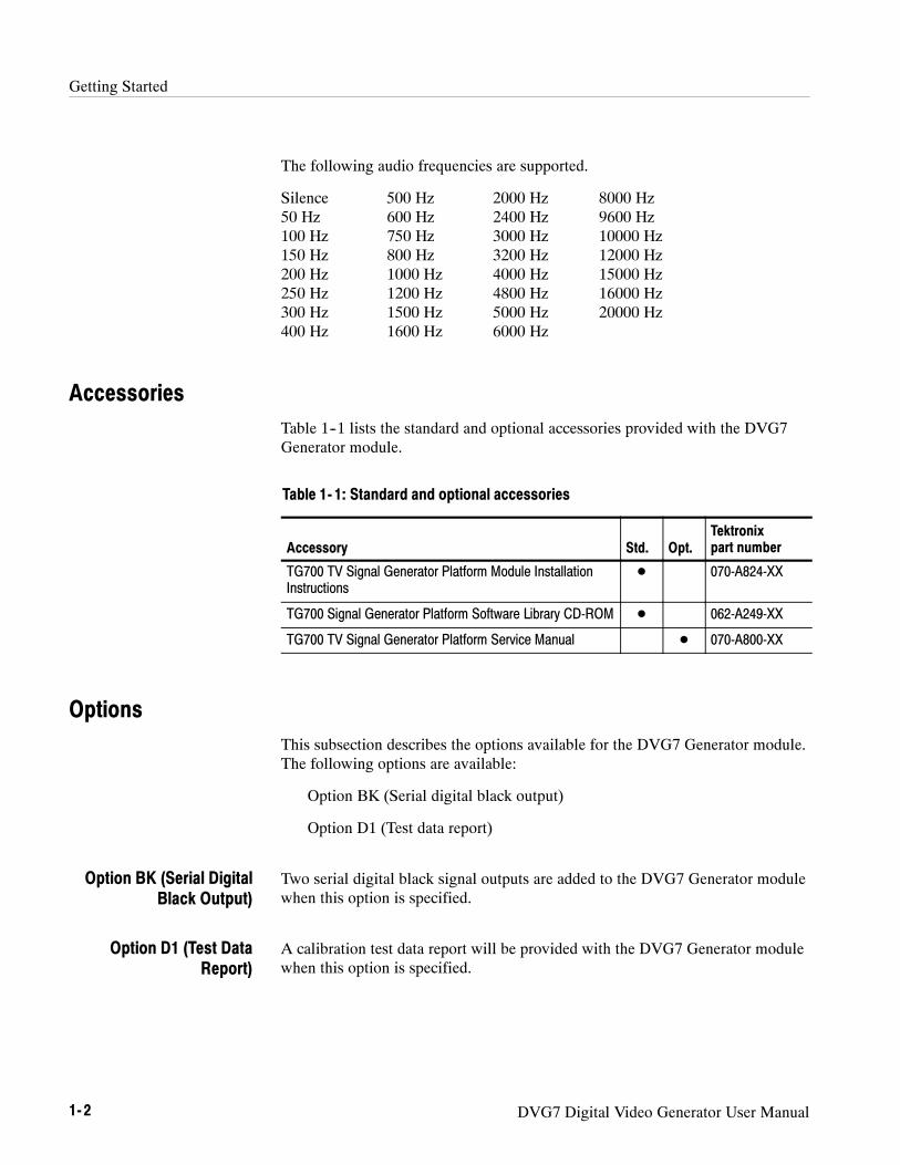
Getting Started
1- 2 DVG7 Digital Video Generator User Manual
The following audio frequencies are supported.
Silence 500 Hz 2000 Hz 8000 Hz50 Hz 600 Hz 2400 Hz 9600 Hz100 Hz 750 Hz 3000 Hz 10000 Hz150 Hz 800 Hz 3200 Hz 12000 Hz200 Hz 1000 Hz 4000 Hz 15000 Hz250 Hz 1200 Hz 4800 Hz 16000 Hz300 Hz 1500 Hz 5000 Hz 20000 Hz400 Hz 1600 Hz 6000 Hz
AccessoriesTable 1--1 lists the standard and optional accessories provided with the DVG7Generator module.
Table 1- 1: Standard and optional accessories
Accessory Std. Opt.Tektronixpart number
TG700 TV Signal Generator Platform Module InstallationInstructions
D 070-A824-XX
TG700 Signal Generator Platform Software Library CD-ROM D 062-A249-XX
TG700 TV Signal Generator Platform Service Manual D 070-A800-XX
OptionsThis subsection describes the options available for the DVG7 Generator module.The following options are available:
Option BK (Serial digital black output)
Option D1 (Test data report)
Two serial digital black signal outputs are added to the DVG7 Generator modulewhen this option is specified.
A calibration test data report will be provided with the DVG7 Generator modulewhen this option is specified.
Option BK (Serial DigitalBlack Output)
Option D1 (Test DataReport)

Getting Started
DVG7 Digital Video Generator User Manual 1- 3
InstallationRefer to the TG700 TV Signal Generator Platform Module InstallationInstructions for instructions on how to install the DVG7 Generator module.
Functional CheckThe following procedure determines whether the module is operating correctly.
The following equipment is required for the functional check:
H Serial digital waveform monitor
H 75 Ω BNC cable
1. Install the module into the TG700 Platform mainframe using the installationprocedures described in the TG700 TV Signal Generator Platform UserManual.
2. Power on the TG700 TV Signal Generator Platform by connecting it to thepower source. The initialization of all the installed modules is executed.
3. Check that no error messages appear on the LCD display.
4. Warm up the instrument for 20 minutes.
5. Press the front-panelMODULE button until the DVG7 main menu shownbelow appears.
DVG7 [x] : STATUS : 525--270100% Color Bars
6. Press the FORMAT button and use the left (A) or right (") arrow button toselect a format, then press the ENTER button.
7. Press one of the front-panel test signal buttons (for example COLOR BAR)to output a signal.
8. Connect the SIGNAL 1 connector to the serial digital waveform monitorusing the 75 Ω BNC cable.
9. Set the waveform monitor to view the signal.
10. Check that the signal appears as expected. For example, if you selected acolor bar signal in step 7, check that the color bar signal appears.
Required equipment
Procedure

Getting Started
1- 4 DVG7 Digital Video Generator User Manual
11. Disconnect the BNC cable from the SIGNAL 1 connector, and then connectthe BNC cable to the SIGNAL 2 connector.
12. Check that the signal appears as expected.

Operating Basics


DVG7 Digital Video Generator User Manual 2- 1
Operating Basics
This section explains the operation of the DVG7 Generator module using thefront-panel buttons and menus. It also contains descriptions of the rear-panelconnectors.
Refer to the TG700 TV Signal Generator Platform User Manual for a detailedexplanation of the front-panel buttons and the LCD display.
Operating ProcedureAfter the module is installed in the mainframe, and the mainframe is installed inthe rack or other location where it will be used, access each function of themodule with the following procedure:
1. Connect the power connector on the rear panel to the AC electric powersource using the power cord.
Electric power is supplied to the mainframe.
2. Wait until the power up initialization process is complete, and check that noerror messages appear on the display.
3. Following the initialization process the mainframe main menu appears, asshown below.
TG700 : PRESET
4. Press the front-panelMODULE button until the DVG7 module main menuappears, as shown below.
DVG7 [x] : STATUS : 525--270100% Color Bars
5. Select the signal format and the signal you want to output. Refer to Selectingan Output Signal on page 2--2 for more information.
6. Press the front-panel arrow buttons to select the desired main menu item orsubmenu item.
Refer to DVG7 Module Main Menu beginning on page 2--6 for detailedinformation about the main menu items and the submenu items.

Operating Basics
2- 2 DVG7 Digital Video Generator User Manual
Selecting an Output SignalWhen you output a signal from the DVG7 Generator module, you need to selecta signal format and output signal. This subsection provides instructions on howto output a signal.
If you press the front-panel FORMAT button when the DVG7 Generator moduleis selected (active), you can select the format for the output signals.
Perform the following steps to select the format:
1. Confirm that any menu item of the DVG7 module main menu is displayed.If the menu is not displayed, press the front-panelMODULE button untilthe DVG7 module main menu appears, as shown below.
DVG7 [x] : STATUS : 525--270100% Color Bars
2. Press the FORMAT button. The menu display changes as follows:
DVG7 [x] : SELECT FORMAT525--270 (Current)
3. Press the left (A) or right (") arrow button to select one of the signalformats, and then press the ENTER button to confirm the selection.
NOTE. When you change signal format, synchronization shock occurs.
When you change the format while a signal is output, the instrument startsloading all of the signal set for the format and displays the message “NowLoading...”. When you see the message, “Done (Press CANCEL)”, pressthe CANCEL button.
All signal sets available in the module are already assigned to the correspondingtest signal buttons (see Figure 2--1). When you press any of the buttons, one ofthe signals in the signal set is output.
For example, when you press the COLOR BAR test signal button, you canoutput the 100% Color Bars signal in the Color Bars signal set.
Press the left (A) or right (") arrow button, or press the test signal buttonrepeatedly to select different signals assigned to the test signal button.
Selecting a Format
Selecting a Signal

Operating Basics
DVG7 Digital Video Generator User Manual 2- 3
Test signal buttons
Figure 2- 1: Front-panel test signal buttons
Table 2--1 lists the signal set assigned to each test signal button and the signalsthat can be selected in the signal set. The signals available in each signal set aredifferent from one signal format to another.
Table 2- 1: Signal set assigned to the test signal buttons
Button name Signal set Signals in the signal set
525- 143 format
COLOR BAR Color Bars 100% Color Bars, 75% Color Bars,SMPTE Color Bars
LINEARITY Linearity 10 Step, 5 Step, Luminance Ramp,Mod Shallow Ramp, Modulated 10 Step,Modulated 5 Step, Modulated Pedestal,Modulated Ramp, Shallow Ramp,Shallow Ramp Matrix
FLAT FIELD Flat Fields 0% Flat Field, 100% Flat Field, 50 % Flat Field,Black Burst, Field Square Wave
MULTI BURST Multi Burst 60 IRE Multiburst, Multipulse
SWEEP Sweep 6 MHz Sweep, SinX/X
MONITOR Monitor 100% Red Field, 2 Level Ped. & Pluge,4 Level Ped. & Pluge, 75% Red Field,Convergence Pattern, Grey Window,Monitor Matrix, Monitor Setup, White Window
PULSE BAR Pulse & Bar Window 1T Pulse & Bar,Window 2T Pulse & Bar
TIMING ------ -- -- ----------
SDI SDI Test Equalizer Test, PLL Test, SDI Matrix
OTHER Other FCC Composite, FCC Multiburst,NTC7 Combination, NTC7 Composite

Operating Basics
2- 4 DVG7 Digital Video Generator User Manual
Table 2- 1: Signal set assigned to the test signal buttons (Cont.)
Button name Signals in the signal setSignal set
525- 270 format
COLOR BAR Color Bars 100% Color Bars, 75% Color Bars,SMPTE Color Bars
LINEARITY Linearity 10 Step, 3 Channel Ramp, 5 Step,B-Y Valid Ramp, Limit Ramp,Modulated Ramp, Oversize Ramp,R-Y Valid Ramp, Shallow Ramp,Shallow Ramp Matrix, Valid Ramp,Y Valid Ramp
FLAT FIELD Flat Fields 0% Flat Field, 100% Flat Field, 50 % Flat Field,Field Square Wave
MULTI BURST Multi Burst 60% Multiburst, Multipulse
SWEEP Sweep 100% Sweep, 60% Sweep, SinX/X
MONITOR Monitor 2 Level Ped. & Pluge, 4 Level Ped. & Pluge,Convergence Pattern, Gamut Test,Grey Window, White Window
PULSE BAR Pulse & Bar 2T Pulse and Bar, T Pulses
TIMING Timing 2.5 MHz Bowtie, 500 kHz Bowtie,Active Picture Timing, Co-Siting Pulse
SDI SDI Test Equalizer Test, PLL Test, SDI Matrix
OTHER Other Chroma Freq. Resp., Color Palette,FCC Composite, FCC Multiburst,NTC7 Combination, NTC7 Composite

Operating Basics
DVG7 Digital Video Generator User Manual 2- 5
Table 2- 1: Signal set assigned to the test signal buttons (Cont.)
Button name Signals in the signal setSignal set
625- 270 format
COLOR BAR Color Bars 100% Colour Bars, 75% Colour Bars,100% Colour Bars Over Red,75% Colour Bars Over Red
LINEARITY Linearity 10 Step, 3 Channel Ramp, 5 Step,B-Y Valid Ramp, Limit Ramp,Modulated Ramp, Oversize Ramp,R-Y Valid Ramp, Shallow Ramp,Shallow Ramp Matrix, Y Valid Ramp
FLAT FIELD Flat Fields 0% Flat Field, 100% Flat Field, 50 % Flat Field,Field Square Wave
MULTI BURST Multi Burst 60% Multiburst
SWEEP Sweep 100% Sweep, 60% Sweep, SinX/X
MONITOR Monitor 100% Red Field, 2 Level Ped. & Pluge,4 Level Ped. & Pluge, 75% Red Field,Convergence Pattern, Gamut Test,Grey Window, White Window
PULSE BAR Pulse & Bar 2T 4T 10T Pulse & Bar,2T 4T 20T Pulse & Bar
TIMING Timing 2.5 MHz Bowtie, 500 kHz Bowtie,Active Picture Timing, Co-Siting Pulse
SDI SDI Test Equalizer Test, PLL Test, SDI Matrix
OTHER Other CCIR 17, CCIR 18, CCIR 330, CCIR 331,CCIR 331 G2
If you want to output custom signals from the module, you must assign thesignal set to one of the test signal buttons. Refer to TG700 TV Signal GeneratorPlatform User Manual for detailed information about how to assign a signal setto a test signal button.

Operating Basics
2- 6 DVG7 Digital Video Generator User Manual
DVG7 Module Main MenuYou can set the logo, circle, and text overlay, embedded audio, timing offset ofthe serial digital signal outputs using the DVG7 module main menu.
Use the up (Y) or down (B) arrow button to scroll through the main menu.Figure 2--2 shows the DVG7 module main menu.
DVG7 [x] : STATUS : 525--270100% Color Bars
DVG7 [x] : TIMING
To AUDIO GROUP submenu(page 2--14)
ENTER
CANCEL
Selection by the MODULE button
DVG7 [x] : MOVING PICTURE
DVG7 [x] : OVERLAY
DVG7 [x] : AUDIO (EMBEDDED)Group 1
To OVERLAY submenu(page 2--9)
ENTER
CANCEL
To MOVING PICTURE submenu(page 2--8)
ENTER
CANCEL
To TIMING submenu(page 2--17)
ENTER
CANCEL
To VIDEO submenu(page 2--18)
ENTER
CANCEL
DVG7 [x] : VIDEO
Group 1Group 2Group 3Group 4
To BLACK submenu(page 2--20)
ENTER
CANCEL
DVG7 [x] : BLACK (OPTION)
Option BK only
Figure 2- 2: DVG7 module main menu

Operating Basics
DVG7 Digital Video Generator User Manual 2- 7
MOVING PICTURE. Scrolls the active picture area of the output test signal. Whenyou select this menu item and then press the ENTER button, you will access theMOVING PICTURE submenu. Refer to MOVING PICTURE Submenu on page2--8 for detailed information.
OVERLAY. Selects an item (logo, text, or circle) that is overlaid on the output testsignal and sets the blinking mode for the overlay. When you select this menuitem and then press the ENTER button, you will access the OVERLAYsubmenu. Refer to OVERLAY Submenu on page 2--9 for detailed information.
AUDIO (EMBEDDED). Sets the parameters for embedded audio on the output testsignals. Use the left (A) or right (") arrow button to select Group 1, Group 2,Group 3, or Group 4. When you select any of the items and then press theENTER button, you will access the AUDIO GROUP submenu. Refer to AUDIOGROUP Submenu on page 2--14 for detailed information.
TIMING. Sets the timing offset of the serial digital video outputs relative to theinternal reference signal (frame reset signal). When you select this menu itemand then press the ENTER button, you will access the TIMING submenu. Referto TIMING Submenu on page 2--17 for detailed information.
VIDEO. Enables or disables the Y, Pb, or Pr component of the output serialdigital video signals, the EDH (Error Detection Handling) insertion, and theoutput mode for an audio/video timing measurement. You can also set theresolution of the output serial digital video signals. When you select this menuitem and then press the ENTER button, you will access the VIDEO submenu.Refer to VIDEO Submenu on page 2--18 for detailed information.
BLACK (OPTION). This menu is only available with Option BK, and sets theparameters of the serial digital black signals output from the BLACK 1 andBLACK 2 connectors. When you select this menu item and then press theENTER button, you will access the BLACK submenu. Refer to BLACKSubmenu on page 2--20 for detailed information.

Operating Basics
2- 8 DVG7 Digital Video Generator User Manual
This menu allows you to scroll the active picture area of the serial digital videosignal up/down or left/right (or randomly). Use the up (Y) or down (B) arrowbutton to scroll the menu. Figure 2--3 shows the MOVING PICTURE submenu.
DVG7 [x] : MOVING PICTUREH Step : 0 Sample (s)
DVG7 [x] : MOVING PICTUREV Step : 0 Line (s)
DVG7 [x] : MOVING PICTUREPeriod : 1 Frame (s)
Select MOVING PICTUREin the main menu
DVG7 [x] : MOVING PICTURERandom : Disable
DisableEnable
Set the number of lines to be scrolled
Set the period, in frames, to be scrolled
Set the number of samples to be scrolled
Figure 2- 3: MOVING PICTURE submenu
H H Step: Sets the number of samples to be scrolled per frame set in thePeriod menu item. Use the left (A) or right (") arrow button to change thevalue. You can set the value from --252 to +252 in 4 samples steps.
H V Step: Sets the number of lines to be scrolled per frame set in the Periodmenu item. Use the left (A) or right (") arrow button to change the value.You can set the value from --252 to +252 in 1 line steps.
H Period: Sets the time interval between occurrences of the scrolling. Use theleft (A) or right (") arrow button to change the value. You can set the valuefrom 1 to 16 in 1 frame steps.
H Random: Sets whether or not the picture scrolls randomly. Use the left (A)or right (") arrow button to select between Disable and Enable. Press theENTER button to confirm the selection.
MOVING PICTURESubmenu

Operating Basics
DVG7 Digital Video Generator User Manual 2- 9
This menu allows you to select an item (logo, ID Text, or circle) to overlay onthe output test signal, and to set the blinking mode for the overlay. Use the up(Y) or down (B) arrow button to scroll through the menu. Figure 2--4 shows theOVERLAY submenu.
DVG7 [x] : OVERLAY : OBJECTLogo
Select OVERLAYin the main menu
DVG7 [x] : OVERLAY : BLINKOFF
OFFFastSlow
To LOGO submenu (page 2--10)To ID TEXT submenu (page 2--11)To CIRCLE submenu (page 2--12)
ENTER
CANCEL
LogoID TextCircle
Figure 2- 4: OVERLAY submenu
H OBJECT: Selects an item that is overlaid on the output test signal. Use theleft (A) or right (") arrow button to select Logo, ID Text, or Circle. Whenyou select any of these items and then press the ENTER button, you willaccess the submenu for setting that overlay. Refer to LOGO Submenu onpage 2--10, ID TEXT Submenu on page 2--11, or CIRCLE Submenu on page2--12 for detailed information.
H BLINK: Sets the blinking mode for the overlay. Use the left (A) or right(") arrow button to select OFF, Fast (blinks approximately at 0.5 secondinterval), or Slow (blinks approximately at 1.0 interval). Press the ENTERbutton to confirm the selection.
OVERLAY Submenu

Operating Basics
2- 10 DVG7 Digital Video Generator User Manual
This menu allows you to select a logo to overlay on the output test signal, and toset the display position of the logo. Use the up (Y) or down (B) arrow button toscroll through the menu. Figure 2--5 shows the LOGO submenu.
DVG7 [x] : OVERLAY : LOGOX Position : 0.0 % APH
Select OFF or a logo
DVG7 [x] : OVERLAY : LOGOY Position : 0.0 % APH
DVG7 [x] : OVERLAY : LOGOLogo : OFF
Select Logo in theOVERLAY submenu
Set the horizontal position
Set the vertical position
DVG7 [x] : OVERLAY : LOGO : SAVEPress ENTER to save parameters
ENTERSave the display position for the logo
Figure 2- 5: LOGO submenu
H X Position: Sets the horizontal position of the logo. The position is set as apercentage of active picture width. Use the left (A) or right (") arrow buttonto change the position. You can set the value from --100.0 % to 0.0 % in0.1% steps.
H Y Position: Sets the vertical position of the logo. The position is set as apercentage of active picture height. Use the left (A) or right (") arrowbutton to change the position. You can set the value from --100.0 % to 0.0 %in 0.1% steps.
H Logo: Selects the logo you want to display. Use the left (A) or right (")arrow button to select OFF or a logo file name. Press the ENTER buttonconfirm the selection. When you select OFF, the logo overlay is disabled.
H SAVE: Saves the display position for the logo to the logo file. Press theENTER button to save the current settings.
LOGO Submenu

Operating Basics
DVG7 Digital Video Generator User Manual 2- 11
In order to display a logo using the LOGO submenu, you need to create the logofile (.lgo) and download it to the LOGO folder of the module.
Refer to the TG700 TV Signal Generator Platform User Manual for detailedinformation about how to create a logo file and download it to the TG700.
This menu allows you to edit text that is overlaid on the output test signal, and toset the display position of the text. Use the up (Y) or down (B) arrow button toscroll through the menu. Figure 2--6 shows the ID TEXT submenu.
DVG7 [x] : OVERLAY : TEXTStatus : Enable
Edit text
DVG7 [x] : OVERLAY : TEXTX Position : 0.0 % APH
DVG7 [x] : OVERLAY : TEXT : EDIT_
Set the horizontal position
Set the vertical positionDVG7 [x] : OVERLAY : TEXTY Position : 0.0 % APH
DisableEnable
DVG7 [x] : OVERLAY : TEXT : SAVE ENTERSave the text to the signal file
Select ID Text in theOVERLAY submenu
ENTER
Figure 2- 6: ID TEXT submenu
ID TEXT Submenu

Operating Basics
2- 12 DVG7 Digital Video Generator User Manual
H Status : Enables or disables the text overlay. Use the left (A) or right (")arrow button to select between Enable and Disable. Press the ENTERbutton to confirm the selection.
H X Position: Sets the horizontal position of the text. The position is set as apercentage of active picture width. Use the left (A) or right (") arrow buttonto change the position. You can set the value from 0.0 % to 100.0 % in 1%steps.
H Y Position: Sets the vertical position of the text. The position is set as apercentage of active picture height. Use the left (A) or right (") arrowbutton to change the position. You can set the value from 0.0 % to 100.0 %in 1% steps.
H EDIT: Edits the text you want to display on the output test signal.
To edit the text, first press the ENTER button to enable the text edit mode.Use the left (A) or right (") arrow button to move the underscore character( _ ) to the character you want to change, and then use the up (Y) or down(B) arrow button to select the desired character. When you enter all of thedesired characters then press the ENTER button to end the text editingprocess. You can use up to 30 characters for the text. Use the blank characterto erase an unneeded character(s).
H SAVE: Saves the text and its position to the signal file currently beingoutput. Press the ENTER button to save the text and its position to thesignal file.
This menu allows you to create a circle overlaid on the output test signal and setits position on the display. Use the up (Y) or down (B) arrow button to scrollthrough the menu. Figure 2--7 shows the CIRCLE submenu.
CIRCLE Submenu

Operating Basics
DVG7 Digital Video Generator User Manual 2- 13
DVG7 [x] : OVERLAY : CIRCLEStatus : Enable
Set the diameter of the circle
DVG7 [x] : OVERLAY : CIRCLEX Position : 0.0 % APH
DVG7 [x] : OVERLAY : CIRCLEDiameter : 10.0 % APH
Set the horizontal position
Set the vertical positionDVG7 [x] : OVERLAY : CIRCLEY Position : 0.0 % APH
DisableEnable
Select Circle in theOVERLAY submenu
Figure 2- 7: CIRCLE submenu
H Status : Enables or disables the circle overlay. Use the left (A) or right (")arrow button to select between Enable and Disable. Press the ENTERbutton to confirm the selection.
H X Position: Sets the horizontal position of the circle. The position is set as apercentage of active picture width. Use the left (A) or right (") arrow buttonto change the position. You can set the value from --50.0 % to 50.0 % in 1%steps.
H Y Position: Sets the vertical position of the circle. The position is set as apercentage of active picture height. Use the left (A) or right (") arrowbutton to change the position. You can set the value from --50.0 % to 50.0 %in 1% steps.
H Diameter: Sets the diameter of the circle. The diameter is set as a percentageof active picture height. Use the left (A) or right (") arrow button to changethe value. You can set the value from 0.0 % to 100.0 % in 1% steps.

Operating Basics
2- 14 DVG7 Digital Video Generator User Manual
This menu allows you to enable or disable embedded audio of the selected audiogroup, select which audio channel to enable, and set the emphasis status bits,sampling alignment status bits, and sample bits of the selected audio group. Usethe up (Y) or down (B) arrow button to scroll through the menu. Figure 2--8shows the AUDIO GROUP submenu.
DVG7 [x] : AUDIO : GRP--1Status : Enable
DVG7 [x] : AUDIO : GRP--1Channel : 1
DVG7 [x] : AUDIO : GRP--1Sampling : Frame
Select any of the audio groups in theAUDIO (EMBEDDED) main menu
NO EMPHASISCDCCITT
FrameFrame without Frame NumberAsynchronous
DVG7 [x] : AUDIO : GRP--1Emphasis : NO EMPHASIS
1234
24 bits20 bits
To AUDIO CHANNEL submenu
ENTER
CANCEL
DVG7 [x] : AUDIO : GRP--1Resolution : 24 bits
DisableEnable
Figure 2- 8: AUDIO GROUP submenu
H Status : Enables or disables the generation of embedded audio for theselected audio group. Use the left (A) or right (") arrow button to selectbetween Enable and Disable. Press the ENTER button to confirm theselection.
H Channel: Selects the channel where you will change the parameters. Use theleft (A) or right (") arrow button to select 1, 2, 3, or 4. When you select anyof the channels and then press the ENTER button you access the AUDIOCHANNEL submenu. Refer to AUDIO CHANNEL Submenu on page 2--15for detailed information.
AUDIO GROUP Submenu

Operating Basics
DVG7 Digital Video Generator User Manual 2- 15
H Emphasis: Sets the emphasis status bits for the selected audio group. Usethe left (A) or right (") arrow button to select NO EMPHASIS, CD, orCCITT. Press the ENTER button to confirm the selection.
H Sampling: Sets the sampling alignment status bits for the selected audiogroup. Use the left (A) or right (") arrow button to select Frame, Framewithout Frame Number, or Asynchronous. Press the ENTER button toconfirm the selection.
H Resolution: Sets the resolution of the audio signal data for the selected audiogroup. Use the left (A) or right (") arrow button to select between 24 bitsand 20 bits. Press the ENTER button to confirm the selection.
This menu allows you to set the frequency, amplitude, and audio click of theembedded audio signal for the selected audio channel. Use the up (Y) or down(B) arrow button to scroll through the menu. Figure 2--9 shows the AUDIOCHANNEL submenu.
DVG7 [x] : AUDIO : GRP--1 : CH--1Frequency : 1000 Hz
DVG7 [x] : AUDIO : GRP--1 : CH--1Amplitude : --20.0 dBFS
--60 dBFS to 0 dBFS
Select any of the channels in the ChannelAUDIO GROUP submenu
DVG7 [x] : AUDIO : GRP--1 : CH--1Audio Click : OFF
OFF1 sec2 sec3 sec4 sec
Inactive 300 Hz 1200 Hz 4000 Hz 12000 HzSilence 400 Hz 1500 Hz 4800 Hz 15000 Hz50 Hz 500 Hz 1600 Hz 5000 Hz 16000 Hz100 Hz 600 Hz 2000 Hz 6000 Hz 20000 Hz150 Hz 750 Hz 2400 Hz 8000 Hz200 Hz 800 Hz 3000 Hz 9600 Hz250 Hz 1000 Hz 3200 Hz 10000 Hz
Figure 2- 9: AUDIO CHANNEL submenu
AUDIO CHANNELSubmenu

Operating Basics
2- 16 DVG7 Digital Video Generator User Manual
H Frequency : Sets the audio signal frequency of the selected audio channel.Use the left (A) or right (") arrow button to select the frequency. Theselection items are as follows:
Inactive 400 Hz 1600 Hz 6000 HzSilence 500 Hz 2000 Hz 8000 Hz50 Hz 600 Hz 2400 Hz 9600 Hz100 Hz 750 Hz 3000 Hz 10000 Hz150 Hz 800 Hz 3200 Hz 12000 Hz200 Hz 1000 Hz 4000 Hz 15000 Hz250 Hz 1200 Hz 4800 Hz 16000 Hz300 Hz 1500 Hz 5000 Hz 20000 Hz
When Inactive is selected, the audio data output is disabled. Press theENTER button to confirm the selection.
H Amplitude : Sets the audio signal amplitude of the selected audio channel.Use the left (A) or right (") arrow button to set the amplitude. You can setthe value from --60 dBFS to 0 dBFS in 1 dBFS steps.
H Audio Click : Inserts audio clicks in the selected audio channel. The audiotone, if any, is turned off for an interval around the audio click. Use the left(A) or right (") arrow button to make the selection. The choices are OFF, 1sec, 2 sec, 3 sec, and 4 sec. Press the ENTER button to enable the selection.
Audio Click becomes valid when you select 1 sec to 4 sec for the AudioClick rate. When Audio Click is valid, Audio Tone is turned off for 0.25second around the click. For example, if you select 3 sec for the click rate,the audio tone will be output for 2.75 seconds, and silent for 0.25 second; theclick occurs during this silence. When Audio Click is OFF, the Audio Toneselected in the FREQUENCY menu is output continuously. Audio Clickmakes it easy to identify any channel(s) of the four output channels.

Operating Basics
DVG7 Digital Video Generator User Manual 2- 17
This menu allows you to adjust the timing offset of the serial digital videooutputs relative to the internal reference signal (frame reset signal). Use the up(Y) or down (B) arrow button to change the menu items. Figure 2--10 shows theTIMING submenu.
DVG7 [x] : TIMINGVertical : 0 Line(s)
DVG7 [x] : TIMINGHorizontal : 0.0000 msec
Set the vertical timing
Select TIMINGin the main menu
Set the horizontal timing
Figure 2- 10: TIMING submenu
H Vertical: Sets the vertical timing offset. Use the left (A) or right (") arrowbutton to change the timing offset. You can set the value within 1/2 frame for525--270 and 625--270 formats, and from --1 to +1 frame for 525--143 formatin 1-line steps.
H Horizontal: Sets the horizontal timing offset. Use the left (A) or right (")arrow button to change the timing offset. You can set the value from --1 to +1line in 1-clock (37.0 ns for 525-270 and 625-270 formats, 69.8 ns for525-143 format) steps.
NOTE. You can reset the timing offset to zero by pressing the left (A) and right(") arrow buttons simultaneously.
TIMING Submenu

Operating Basics
2- 18 DVG7 Digital Video Generator User Manual
This menu allows you to turn the Y, Pb, or Pr component of the serial digitalvideo signals and the insertion of the EDH (Error Detection and Handling) on oroff individually. You can also set the resolution of the serial digital video signals,and turn the output mode for an audio/video timing measurement. Use the up(Y) or down (B) arrow button to scroll through the menu. Figure 2--11 showsthe VIDEO submenu.
Select VIDEO in the main menu
DVG7 [x] : VIDEOY : ON
DVG7 [x] : VIDEOPb : ON
ONOFF
DVG7 [x] : VIDEOPr : ON
ONOFF
ONOFF
DVG7 [x] : VIDEOResolution : 10 bits
10 bits8 bits
DVG7 [x] : VIDEOEDH : ON
ONOFF
DVG7 [x] : VIDEOAV Timing Mode : OFF
OFFON
Figure 2- 11: VIDEO submenu
H Y: Turns the Y component of the serial digital video signals on or off. Usethe left (A) or right (") arrow button to select between ON and OFF. Pressthe ENTER button to confirm the selection.
H Pb: Turns the Pb component of the serial digital video signals on or off. Usethe left (A) or right (") arrow button to select between ON and OFF. Pressthe ENTER button to confirm the selection.
VIDEO Submenu

Operating Basics
DVG7 Digital Video Generator User Manual 2- 19
H Pr: Turns the Pr component of the serial digital video signals on or off. Usethe left (A) or right (") arrow button to select between ON and OFF. Pressthe ENTER button to confirm the selection.
H Resolution: Sets the resolution of the serial digital video signals. Use the left(A) or right (") arrow button to select between 10 bits and 8 bits. Press theENTER button to confirm the selection.
H EDH: Turns the insertion of the EDH (Error Detection and Handling)information on or off on the serial digital video signals. Use the left (A) orright (") arrow button to select between ON and OFF. Press the ENTERbutton to confirm the selection.
H AV Timing Mode: Turns the output mode for an audio/video timingmeasurement on or off. Use the left (A) or right (") arrow button to selectbetween ON and OFF. Press the ENTER button to confirm the selection.
When you turn on this mode, the specified audio and video signals aresynchronously on for 0.5 second and off for 4.5 seconds. With this signal,you can measure the time delay that accumulates between the audio andvideo content of the television signal during signal transport. The time delaycan be measured by a video analyzer with the serial digital video signal or byan oscilloscope with the analog audio and video signals deembedded fromthe serial digital video signal. The following settings are recommended forthe audio and video signals when you use this mode:
Audio signal (CH1 and CH2 of Group 1) : 10000 Hz, --20 dBFSVideo signal: 100% Flat Field
NOTE. The AV Timing Mode setting is not saved as a preset.

Operating Basics
2- 20 DVG7 Digital Video Generator User Manual
This menu allows you to set the output parameters of the serial digital blacksignals output from the BLACK1 and BLACK 2 connectors. Use the up (Y) ordown (B) arrow button to change the menu items. Figure 2--12 shows theBLACK submenu.
DVG7 [x] (BLACK) : FORMAT525--143
DVG7 [x] (BLACK) : SIGNALBlack
DVG7 [x] (BLACK) : AUDIO (EMBEDDED)Group 1
Select BLACK (OPTION )in the main menu
DVG7 [x] (BLACK) : TIMING
Black40% Flat Field50% Flat Field100% Flat Field
Group 1Group 2Group 3Group 4
To AUDIO GROUP submenu
ENTER
CANCEL
To TIMING submenu
ENTER
CANCEL
525--143525--270625--270
DVG7 [x] (BLACK) : VIDEO To VIDEO submenu
ENTER
CANCEL
Figure 2- 12: BLACK submenu (Option BK only)
BLACK Submenu(Option BK Only)

Operating Basics
DVG7 Digital Video Generator User Manual 2- 21
FORMAT. Selects the format of the output serial digital black signals. Use the left(A) or right (") arrow button to select 525--143, 525--270, or 625--270. Press theENTER button to confirm the selection.
SIGNAL. Selects the serial digital black signal to output. Use the left (A) or right(") arrow button to select between Black (serial digital black), 40% Flat Field,50% Flat Field, and 100% Flat Field. Press the ENTER button to confirm theselection.
AUDIO (EMBEDDED). Sets the parameters for embedded audio on the serialdigital black signals. Use the left (A) or right (") arrow button to select Group1, Group 2, Group 3, or Group 4. When you select any of the groups and thenpress the ENTER button, you will access the AUDIO GROUP submenu. Referto AUDIO GROUP Submenu on page 2--14 for detailed information.
TIMING. Sets the timing offset of the serial digital black outputs relative to theinternal reference signal (frame reset signal). When you select this menu itemand then press the ENTER button, you will access the TIMING submenu. Referto TIMING Submenu on page 2--17 for detailed information.
VIDEO. Sets the resolution and EDH insertion of the serial digital black signals.When you select this menu item and then press the ENTER button, you willaccess the VIDEO submenu. Refer to the VIDEO Submenu on page 2--18 fordetailed information.

Operating Basics
2- 22 DVG7 Digital Video Generator User Manual
Rear-Panel ConnectorsThe DVG7 Generator module is equipped with two connectors, SIGNAL 1 andSIGNAL 2 which will output serial digital test signals. If Option BK is installedthere will be two additional connectors, BLACK 1 and BLACK 2, which willoutput serial digital black signals. Figure 2--13 shows the DVG7 Generatormodule with all four connectors installed (Option BK).
NOTE. The SIGNAL 1 and SIGNAL 2 connectors will both output the same testsignal, and the BLACK 1 and BLACK 2 connectors will both output the sameblack signal.
Figure 2- 13: DVG7 module rear-panel connectors (Option BK)
H SIGNAL 1: Serial digital test signal output.
H SIGNAL 2: Serial digital test signal output.
H BLACK 1: Serial digital black output (Option BK only).
H BLACK 2: Serial digital black output (Option BK only).

Operating Basics
DVG7 Digital Video Generator User Manual 2- 23
Factory Default SettingsTable 2--2 shows the factory default settings for the DVG7 Generator module.These settings are recalled when you select Factory Default from the PRESET: RECALL menu item in the mainframe main menu.
Table 2- 2: Factory default settingsMenu item name Settings
STATUS 525--270SMPTE Color Bars
MOVING PICTURE
H Step 0 Sample(s)
V Step 0 Line(s)
Period 1 Frame(s)
Random Disable
OVERLAY : OBJECT Logo
OVERLAY : BLINK OFF
OVERLAY : LOGO
Logo OFF
OVERLAY : ID TEXT
Status Disable
OVERLAY : CIRCLE
Status Disable
X Position 0.0 % APH
Y Position 0.0 % APH
Diameter 90 % APH
AUDIO : GRP--1 to GRP--4
Status Disable
Emphasis No Emphasis
Sampling Frame
Resolution 20 bits
AUDIO : GRP--1 : Ch--1 to CH--4
Frequency 1000 Hz
Amplitude --20.0 dBFS
Audio Click OFF
TIMING
Vertical 0 Line(s)
Horizontal 0.0000 ms

Operating Basics
2- 24 DVG7 Digital Video Generator User Manual
Table 2- 2: Factory default settings (Cont.)Menu item name Settings
VIDEO
Y ON
Pb ON
Pr ON
Resolution 10 bits
EDH ON
AV Timing Mode OFF
Option BK
(BLACK) FORMAT 525--270
(BLACK) SIGNAL Black
(BLACK) AUDIO : GRP--1 to GRP--4
Status Disable
Emphasis No Emphasis
Sampling Frame
Resolution 20 bits
(BLACK) AUDIO : CH--1 to CH--4
Frequency 1000 Hz
Amplitude --20.0 dBFS
Audio Click OFF
(BLACK)TIMING
Vertical 0 Line(s)
Horizontal 0.0000 ms
(BLACK)VIDEO
Resolution 10 bits
EDH ON

Reference


DVG7 Digital Video Generator User Manual 3- 1
Syntax
This section contains information on the Standard Commands for ProgrammableInstruments (SCPI) and the programming structure you can use to program yourDVG7 Generator module.
Programming ModelSpecific conditions must exist before programming commands will affect the testsignal generated by a module.
Select the module using the :INSTrument:SELect command before executingany commands. Many of the commands used by the DVG7 module are shared byseveral modules and will be accepted without a reported error.
Many commands will accept either string or numeric arguments. For example: aboolean argument can either be “1” or “ON“.
Signal parameter commands that have a :STEP node can accept either a numericvalue or they can accept a string argument that refers to the :STEP increment.
Signal parameter commands with a :STEP node will accept the following stringsin addition to a numeric value:
UP.Use this argument to increase the parameter value one increment as definedby the :STEP value.
DOWN.Use this argument to decrease the parameter value one increment asdefined by the :STEP value.
MINimum.Use this argument to set the parameter value to the minimumacceptable value.
MAXimum.Use this argument to set the parameter value to the maximumacceptable value.
DEFault.Use this argument to set the parameter value to the default value.
Selecting the Module
Command Arguments

Syntax
3- 2 DVG7 Digital Video Generator User Manual
If you send a query with no argument, the response is the current value.You can also use MINimum, MAXimum, and DEFault as arguments for querieswhose command form can use these arguments (refer to the command syntax forthe specific command). Instead of returning the current value, queries using thesearguments return the following information:
MINimum. Return the minimum acceptable value.
MAXimum. Return the maximum acceptable value.
DEFault. Return the default value.
The following example demonstrates the effect of each of the arguments whenused with a step value.
1. :INSTrument:SELect "DVG7:#" selects the digital video generator modulelocated in the slot number indicated by the “#” symbol.
2. :OUTPut:CIRCle:STATe ON displays a circle on the video display.
NOTE. :OUTPut:CIRCle:DIAMeter uses an argument that is the percent ofpicture height.
3. :OUTPut:CIRCle:DIAMeter DEFault sets the circle diameter to 90 percentof the screen height.
4. :OUTPut:CIRCle:DIAMeter:STEP 10 sets the step increment to 10 percent.
5. :OUTPut:CIRCle:DIAMeter DOWN changes the circle diameter to 80 percentof the screen height.
6. :OUTPut:CIRCle:DIAMeter 50 changes the circle diameter to 50 percent ofthe screen height.
7. :OUTPut:CIRCle:DIAMeter MAXimum changes the circle diameter to100 percent of the screen height.
8. :OUTPut:CIRCle:DIAMeter MINimum changes the circle diameter to0 percent of the screen height.
9. :OUTPut:CIRCle:DIAMeter UP changes the circle diameter to 10 percent ofthe screen height.
10. :OUTPut:CIRCle:DIAMeter? MAXimum queries the maximum circlediameter (not the current diameter). The query returns the value of 100percent, which is the maximum circle diameter allowable.
Query Arguments
Argument Example

Syntax
DVG7 Digital Video Generator User Manual 3- 3
SCPI Commands and QueriesSCPI is a standard created by a consortium that provides guidelines for remoteprogramming of instruments. These guidelines provide a consistent program-ming environment for instrument control and data transfer. This environmentuses defined programming messages, instrument responses, and data formatacross all SCPI instruments, regardless of manufacturer. The DVG7 Generatormodule uses a command language based on the SCPI standard.
The SCPI language is based on a hierarchical or tree structure (see Figure 3--1)that represents a subsystem. The top level of the tree is the root node; it isfollowed by one or more lower-level nodes.
DIAMeter
OUTPut
CIRCle
POSitionSTATe
Root node
Lower-levelnodes
Figure 3- 1: Example of SCPI subsystem hierarchy
You can create commands and queries from these subsystem hierarchy trees.Commands specify actions for the instrument to perform. Queries returnmeasurement data and information about parameter settings.
For more information on SCPI commands and programming structure, refer tothe TG700 Signal Generator Platform User Manual.

Syntax
3- 4 DVG7 Digital Video Generator User Manual

DVG7 Digital Video Generator User Manual 3- 5
Remote Commands
This section describes the remote commands used to control the DVG7Generator module remotely. The commands to the module are divided into thefollowing three groups:
H MASS MEMORY commands (Refer to the TG700 TV Signal GeneratorPlatform User Manual)
H OUTPUT commands
H SENSE commands
MASS MEMORY CommandsTwo MASS MEMORY commands are listed here for your reference. You canuse these to load and query the output test signal. Detailed information for usingthese commands are located in the TG700 TV Signal Generator Platform UserManual.
:MMEMory:LOAD:SIGNal <module_name>,<signal_name>:MMEMory:LOAD:SIGNal <slot_number>,<signal_name>
Loads a signal into the specified module.
:MMEMory:SIGNal:ACTive? <slot_number>|<module_name>
Returns the current output signal of the specified module.

Remote Commands
3- 6 DVG7 Digital Video Generator User Manual
OUTPUT CommandsUse these commands to control the output parameters of the module. Theseinclude embedded audio and circle/text/logo overlay.
:OUTPut<n>:CIRCle:STATe ON|OFF:DIAMeter <numeric_value>:POSition:HORizontal <numeric_value>:VERTical <numeric_value>
:EAUDio:CHANnel<n>:AMPLitude <numeric_value>:FREQuency <numeric_value>:CLICk OFF|1|2|3|4
:GROup<n>:STATe ON|OFF:PREemphasis OFF|CD|CCITt:NBITs 20|24:SAMPLIng FRAMe|NOFRame|ASYNc
:LOGO:STATe ON|OFF:POSition:HORizontal <numeric_value>:VERTical <numeric_value>
:SELect <logo_name>:SAVe
:MOVe:HORizontal <numeric_value>:VERTical <numeric_value>:PERiod <numeric_value>:RANDom[:STATe] ON|OFF
:OVERlay:BLINk:STATe ON|OFF:PERiod <numeric_value>
:TEXT:STATe ON|OFF:DATA <string>:POSition:HORizontal <numeric_value>:VERTical <numeric_value>
:SAVe
Command Tree

Remote Commands
DVG7 Digital Video Generator User Manual 3- 7
:VIDeo:Y:STATe ON|OFF
:PB:STATe ON|OFF
:PR:STATe ON|OFF
:NBITs 8|10:EDH:STATe ON|OFF
:AVTiming:STATe ON|OFF
:STANdard D2_NTSC|D1_NTSC|D1_PAL:SIGNal BLACk|GRAY|FF50P|WHITe
:OUTPut1:CIRCle:STATe ON|OFF
Turns the circle overlay on the video signal on or off. You can use 1or 0 instead of ON or OFF.
:OUTPut1:CIRCle:STATe?
Returns the current circle overlay state.
:OUTPut1:CIRCle:DIAMeter <numeric_value>
Sets the diameter of the displayed circle. The unit is percent of activepicture height. You can set the diameter from 0 % to 100 % in 1 %steps. You can also use MIN, MAX, or DEF instead of a numericvalue.
:OUTPut1:CIRCle:DIAMeter?
Returns the diameter of the displayed circle.
:OUTPut1:CIRCle:POSition:HORizontal <numeric_value>
Sets the horizontal position of the circle as it appears on the activesignal. The unit is percent of active picture width. You can set theposition from --50 % to +50 % in 1 % steps. You can also use MIN,MAX, or DEF instead of a numeric value.
:OUTPut1:CIRCle:POSition:HORizontal?
Returns the current horizontal position of the circle as it appears onthe active signal.
Command Description

Remote Commands
3- 8 DVG7 Digital Video Generator User Manual
:OUTPut1:CIRCle:POSition:VERTical <numeric_value>
Sets the vertical position of the circle as it appears on the activesignal. The unit is percent of active picture height. You can set theposition from --50 % to +50 % in 1 % steps. You can also use MIN,MAX, or DEF instead of a numeric value.
:OUTPut1:CIRCle:POSition:VERTical?
Returns the current vertical position of the circle as it appears on theactive signal.
:OUTPut<n>:EAUDio:CHANnel<m>:AMPLitude <numeric_value>
Sets the amplitude of a specific embedded audio channel for theselected outputs. You can set the amplitude from --60 dBFS to0 dBFS in 1 dBFS steps. The <n> in the command represents theoutput connector type. “1” represents the SIGNAL connectors and“2” represents the optional BLACK connectors. The <m> in thecommand represents the channel number and you can use anychannel number from 1 through 16.
:OUTPut<n>:EAUDio:CHANnel<m>:AMPLitude?
Returns the current amplitude of a specific embedded audio channelfor the selected outputs. The <n> in the command represents theoutput connector type. “1” represents the SIGNAL connectors and“2” represents the optional BLACK connectors. The <m> in thecommand represents the channel number and you can use anychannel number from 1 through 16.
:OUTPut<n>:EAUDio:CHANnel<m>:FREQuency <numeric_value>
Sets the frequency of a specific embedded audio channel for theselected outputs. The frequency choices are --1, 0, 50, 100, 150, 200,250, 300, 400, 500, 600, 750, 800, 1000, 1200, 1500, 1600, 2000,2400, 3000, 3200, 4000, 4800, 5000, 6000, 8000, 9600, 10000,12000, 15000, 16000, or 20000. For --1, the output of the audio datais disabled. The <n> in the command represents the output connectortype. “1” represents the SIGNAL connectors and “2” represents theoptional BLACK connectors. The <m> in the command representsthe channel number and you can use any channel number from 1through 16.

Remote Commands
DVG7 Digital Video Generator User Manual 3- 9
:OUTPut<n>:EAUDio:CHANnel<m>:FREQuency?
Returns the current frequency of a specific embedded audio channelfor the selected outputs. The <n> in the command represents theoutput connector type. “1” represents the SIGNAL connectors and“2” represents the optional BLACK connectors. The <m> in thecommand represents the channel number and you can use anychannel number from 1 through 16.
:OUTPut<n>:EAUDio:CHANnel<m>:CLICk 0|1|2|3|4
Sets the audio click of a specific audio channel for the selectedoutputs. You can select 0, 1 (second), 2 (seconds), 3 (seconds) or 4(seconds). When 1, 2, 3 or 4 is selected, the audio click becomesvalid. Audio Tone is turned off for 0.25 seconds around the time ofthe click. The <n> in the command represents the output connectortype. “1” represents the SIGNAL connectors and “2” represents theoptional BLACK connectors. The <m> in the command representsthe channel number and you can use any channel number from 1through 16.
:OUTPut<n>:EAUDio:CHANnel<m>:CLICk?
Returns the current audio click settings of a specific audio channelfor the selected outputs. The <n> in the command represents theoutput connector type. “1” represents the SIGNAL connectors and“2” represents the optional BLACK connectors. The <m> in thecommand represents the channel number and you can use anychannel number from 1 through 16.
:OUTPut<n>:EAUDio:GROup<m>:STATe ON|OFF
Turns on or off the output of a specific audio group for the selectedoutputs. You can also use 1 or 0 instead of ON or OFF. The <n> inthe command represents the output connector type. “1” representsthe SIGNAL connectors and “2” represents the optional BLACKconnectors. The <m> in the command represents the group numberand you can use any channel number from 1 through 4.
:OUTPut<n>:EAUDio:GROup<m>:STATe?
Returns the current output state of a specific audio group for theselected outputs. The <n> in the command represents the outputconnector type. “1” represents the SIGNAL connectors and “2”represents the optional BLACK connectors. The <m> in thecommand represents the group number and you can use any channelnumber from 1 through 4.
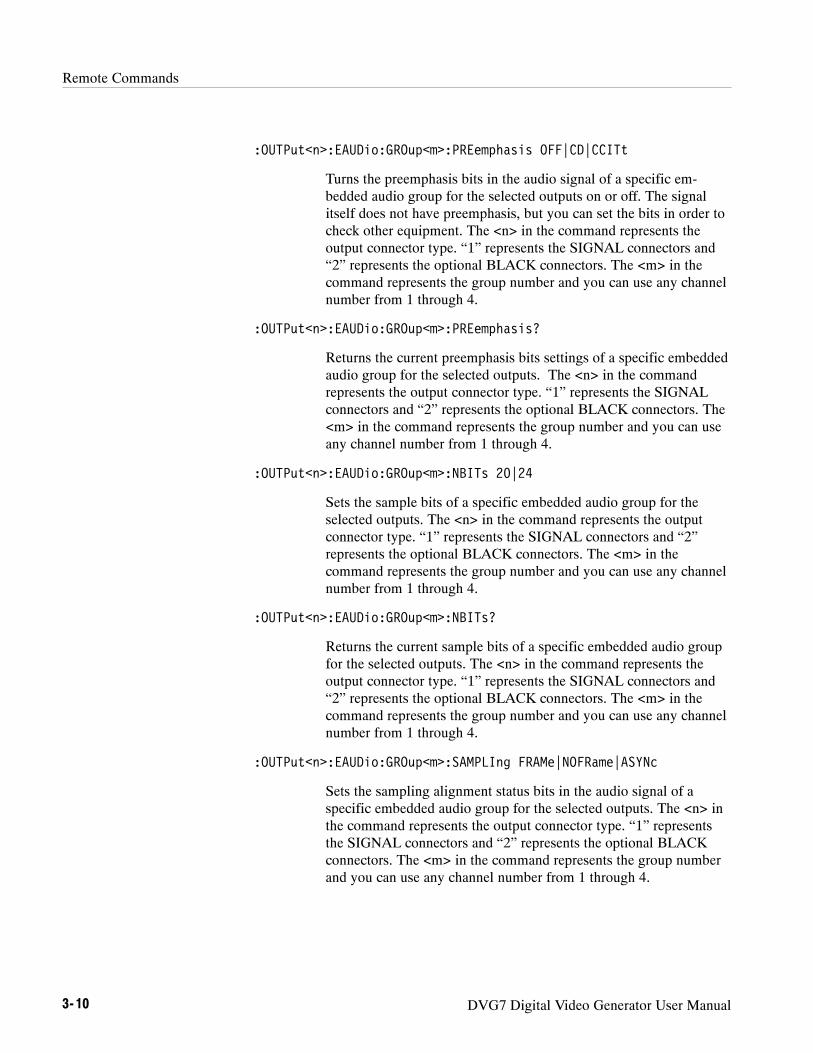
Remote Commands
3- 10 DVG7 Digital Video Generator User Manual
:OUTPut<n>:EAUDio:GROup<m>:PREemphasis OFF|CD|CCITt
Turns the preemphasis bits in the audio signal of a specific em-bedded audio group for the selected outputs on or off. The signalitself does not have preemphasis, but you can set the bits in order tocheck other equipment. The <n> in the command represents theoutput connector type. “1” represents the SIGNAL connectors and“2” represents the optional BLACK connectors. The <m> in thecommand represents the group number and you can use any channelnumber from 1 through 4.
:OUTPut<n>:EAUDio:GROup<m>:PREemphasis?
Returns the current preemphasis bits settings of a specific embeddedaudio group for the selected outputs. The <n> in the commandrepresents the output connector type. “1” represents the SIGNALconnectors and “2” represents the optional BLACK connectors. The<m> in the command represents the group number and you can useany channel number from 1 through 4.
:OUTPut<n>:EAUDio:GROup<m>:NBITs 20|24
Sets the sample bits of a specific embedded audio group for theselected outputs. The <n> in the command represents the outputconnector type. “1” represents the SIGNAL connectors and “2”represents the optional BLACK connectors. The <m> in thecommand represents the group number and you can use any channelnumber from 1 through 4.
:OUTPut<n>:EAUDio:GROup<m>:NBITs?
Returns the current sample bits of a specific embedded audio groupfor the selected outputs. The <n> in the command represents theoutput connector type. “1” represents the SIGNAL connectors and“2” represents the optional BLACK connectors. The <m> in thecommand represents the group number and you can use any channelnumber from 1 through 4.
:OUTPut<n>:EAUDio:GROup<m>:SAMPLIng FRAMe|NOFRame|ASYNc
Sets the sampling alignment status bits in the audio signal of aspecific embedded audio group for the selected outputs. The <n> inthe command represents the output connector type. “1” representsthe SIGNAL connectors and “2” represents the optional BLACKconnectors. The <m> in the command represents the group numberand you can use any channel number from 1 through 4.

Remote Commands
DVG7 Digital Video Generator User Manual 3- 11
:OUTPut<n>:EAUDio:GROup<m>:SAMPLIng?
Returns the current sampling alignment status bits settings of aspecific embedded audio group for the selected outputs. The <n> inthe command represents the output connector type. “1” representsthe SIGNAL connectors and “2” represents the optional BLACKconnectors. The <m> in the command represents the group numberand you can use any channel number from 1 through 4.
:OUTPut1:LOGO:STATe ON|OFF
Turns the logo overlay display on the video signal on or off. You canalso use 1 or 0 instead of ON or OFF.
:OUTPut1:LOGO:STATe?
Returns the current logo overlay state.
:OUTPut1:LOGO:POSition:HORizontal <numeric_value>
Sets the horizontal position of the logo as it appears on the activesignal. The unit is percent of active picture width. You can set theposition from --100 % to 0 % in 0.1 % steps. You can also use MIN,MAX, or DEF instead of a numeric value.
:OUTPut1:LOGO:POSition:HORizontal?
Returns the current horizontal position of the logo.
:OUTPut1:LOGO:POSition:VERTical <numeric_value>
Sets the vertical position of the logo as it appears on the activesignal. The unit is percent of active picture height. You can set theposition from --100 % to 0 % in 0.1 % steps. You can also use MIN,MAX, or DEF instead of a numeric value.
:OUTPut1:LOGO:POSition:VERTical?
Returns the current vertical position of the logo.
:OUTPut1:LOGO:SELect <logo_name>
Selects the logo used for the logo overlay.
:OUTPut1:LOGO:SELect?
Returns the current logo used for the logo overlay.
:OUTPut1:LOGO:SAVe
Saves the current display position of the logo to the logo file. Thereare no arguments.

Remote Commands
3- 12 DVG7 Digital Video Generator User Manual
:OUTPut1:MOVe:HORizontal <numeric_value>
Sets the amount of horizontal scrolling in the moving picture mode.You can set the value from --252 to +252 in 4 samples steps.
:OUTPut1:MOVe:HORizontal?
Returns the amount of horizontal scrolling in the moving picturemode.
:OUTPut1:MOVe:VERTical <numeric_value>
Sets the amount of vertical scrolling in the moving picture mode.You can set the value from --252 to +252 in 1 line steps.
:OUTPut1:MOVe:VERTical?
Returns the amount of vertical scrolling in the moving picture mode.
:OUTPut1:MOVe:PERiod <numeric_value>
Sets the time interval between occurrences of the scrolling. You canset the value from 1 to 16 in 1 field steps.
:OUTPut1:MOVe:PERiod?
Returns the time interval between occurrences of the scrolling.
:OUTPut1:MOVe:RANDom:STATe ON|OFF
Turns the random scrolling mode on or off. You can also use 1 or 0instead of ON or OFF.
:OUTPut1:MOVe:RANDom:STATe?
Returns the current state of the random scrolling mode.
:OUTPut1:OVERlay:BLINk:STATe ON|OFF
Turns on or off the blinking mode for the logo, text, and circleoverlay. You can also use 1 or 0 instead of ON or OFF
:OUTPut1:OVERlay:BLINk:STATe?
Returns the current state of the blinking mode for the logo, text, andcircle overlay.
:OUTPut1:OVERlay:BLINk:PERiod <numeric_value>
Sets the blinking interval of the blinking mode for the logo, text, andcircle overlay. You can set the value as 0.5 seconds or 1.0 seconds.

Remote Commands
DVG7 Digital Video Generator User Manual 3- 13
:OUTPut1:OVERlay:BLINk:PERiod?
Returns the blinking interval of the blinking mode for the logo, text,and circle overlay.
:OUTPut1:TEXT:STATe ON|OFF
Turns the text overlay display on the video signal on or off. You canalso use 1 or 0 instead of ON or OFF.
:OUTPut1:TEXT:STATe?
Returns the current text overlay state.
:OUTPut1:TEXT:DATA <string>
Sets the current string for the text mode.
:OUTPut1:TEXT:DATA?
Returns the current string for the text mode.
:OUTPut1:TEXT:POSition:HORizontal <numeric_value>
Sets the text horizontal position in the video signal. The unit ispercent of active picture width. You can set the position from 0 % to100 % in 1 % steps. You can also use MIN, MAX, or DEF instead ofthe numeric value.
:OUTPut1:TEXT:POSition:HORizontal?
Returns the current text horizontal position in the video signal.
:OUTPut1:TEXT:POSition:VERTical <numeric_value>
Sets the text vertical position in the video signal. The unit is percentof active picture height. You can set the position from 0 % to 100 %in 1 % steps. You can also use MIN, MAX, or DEF instead of thenumeric value.
:OUTPut1:TEXT:POSition:VERTical?
Returns the current text vertical position in the video signal.
:OUTPut1:TEXT:SAVe
Saves the current text and its display position to the signal file.There are no arguments.
:OUTPut1:VIDeo:Y:STATe ON|OFF
Turns the Y component of the serial digital video signals on or off.You can also use 1 or 0 instead of ON or OFF.

Remote Commands
3- 14 DVG7 Digital Video Generator User Manual
:OUTPut1:VIDeo:Y:STATe?
Returns the current output state of the Y component of the serialdigital video signals.
:OUTPut1:VIDeo:PB:STATe ON|OFF
Turns the PB component of the serial digital video signals on or off.You can also use 1 or 0 instead of ON or OFF.
:OUTPut1:VIDeo:PB:STATe?
Returns the current output state of the PB component of the serialdigital video signals.
:OUTPut1:VIDeo:PR:STATe ON|OFF
Turns the PR component of the serial digital video signals on or off.You can also use 1 or 0 instead of ON or OFF.
:OUTPut1:VIDeo:PR:STATe?
Returns the current output state of the PR component of the serialdigital video signals.
:OUTPut<n>:VIDeo:NBITs 8|10
Sets the video resolution for the selected output. The options are8 bits or 10 bits. The <n> in the command represents the outputconnector type. “1” represents the SIGNAL connectors and “2”represents the optional BLACK connectors.
:OUTPut<n>:VIDeo:NBITs?
Returns the current video resolution for the selected outputs. Theoptions are 8 bits or 10 bits. The <n> in the command represents theoutput connector type. “1” represents the SIGNAL connectors and“2” represents the optional BLACK connectors.
:OUTPut<n>:VIDeo:EDH:STATe ON|OFF
Turns Error Detection and Handling insertion for the selectedoutputs on or off. The <n> in the command represents the outputconnector type. “1” represents the SIGNAL connectors and “2”represents the optional BLACK connectors.
:OUTPut1:VIDeo:EDH:STATe?
Returns the current Error Detection and Handling insertion status.

Remote Commands
DVG7 Digital Video Generator User Manual 3- 15
:OUTPut<n>:VIDeo:EDH:STATe?
Returns the current Error Detection and Handling insertion status forthe selected outputs. The <n> in the command represents the outputconnector type. “1” represents the SIGNAL connectors and “2”represents the optional BLACK connectors.
:OUTPut1:VIDeo:AVTiming:STATe ON|OFF
Turns the output mode for an audio/video timing measurement on oroff. Refer to Operating Basics for detailed information about themode. You can also use 1 or 0 instead of ON or OFF.
:OUTPut1:VIDeo:AVTiming:STATe?
Returns the current output mode setting for an audio/video timingmeasurement.
:OUTPut2:STANdard D2_NTSC|D1_NTSC|D1_PAL
Sets the video standard for the serial digital black signals outputfrom the BLACK connectors. The choices are D2_NTSC (525--143format), D1_NTSC (525--270 format), or D1_PAL (625--270format). This command is only available if Option BK is installed.
:OUTPut<n>:STANdard?
Returns the video standard for the selected output. The <n> in thecommand represents the output connector type. “1” represents theSIGNAL connectors and “2” represents the optional BLACKconnectors.
:OUTPut2:SIGNal BLACk|GRAY|FF50P|WHITe
Sets the type of the serial digital black signals output from theBLACK connectors. The options are BLACK (serial digital blacksignal) , GRAY (40% flat field signal), FF50P (50% flat fieldsignal), or WHITe (100% flat field signal). This command is onlyavailable if Option BK is installed.
:OUTPut2:SIGNal?
Returns the current serial digital black signals output from theBLACK connectors. This command is only available if Option BKis installed.
:OUTPut:CONFigure?
Returns the availability of serial digital black signal output option(Option BK). “1” indicates that the option is available and “0”indicates that the option is not available.

Remote Commands
3- 16 DVG7 Digital Video Generator User Manual
SENSE CommandsUse these commands to set the timing offset of the SIGNAL outputs and theBLACK outputs (Option BK only) relative to the internal reference signal (framereset signal).
Refer to Operating Basics for detailed information about the setting range.
:SENSe<n>:CORRection:MDELay:HORizontal <numeric_value>:STEP <numeric_value>
:VERTical <numeric_value>:STEP <numeric_value>
:SENSe<n>:CORRection:MDELay:HORizontal <numeric_value>
Sets the horizontal timing offset of the selected outputs. The timingresolution is clock-cycles. The units are microseconds. You can useUP, DOWN, or DEF instead of the numeric value. If the argumentexceeds the horizontal time value, then the vertical offset is adjustedto accommodate the requested delay. The <n> in the commandrepresents the type of output connector. “1” represents the SIGNALconnectors and “2” represents the BLACK connectors.
:SENSe<n>:CORRection:MDELay:HORizontal?
Returns the current horizontal timing offset of the selected outputs.The <n> in the command represents the type of output connector.“1” represents the SIGNAL connectors and “2” represents theBLACK connectors.
:SENSe<n>:CORRection:MDELay:HORizontal:STEP <numeric_value>
Sets the step increment used by the UP or DOWN commands. Theunits are microseconds. You can use MIN, MAX, or DEF instead ofa numeric value. The <n> in the command represents the type ofoutput connector. “1” represents the SIGNAL connectors and “2”represents the BLACK connectors.
Command Tree
Command Description

Remote Commands
DVG7 Digital Video Generator User Manual 3- 17
:SENSe<n>:CORRection:MDELay:HORizontal:STEP?
Returns the current step increment. The <n> in the commandrepresents the type of output connector. “1” represents the SIGNALconnectors and “2” represents the BLACK connectors.
:SENSe<n>:CORRection:MDELay:VERTical <numeric_value>
Sets the vertical timing offset of the selected outputs. The argumentcan be a floating point value that is translated into integer lines witha horizontal offset. You can use UP, DOWN, or DEF instead of anumeric value. The <n> in the command represents the type ofoutput connector. “1” represents the SIGNAL connectors and “2”represents the BLACK connectors.
:SENSe<n>:CORRection:MDELay:VERTical?
Returns the current vertical timing offset of the selected outputs. The<n> in the command represents the type of output connector. “1”represents the SIGNAL connectors and “2” represents the BLACKconnectors.
:SENSe<n>:CORRection:MDELay:VERTical:STEP <numeric_value>
Sets the step increment used by the UP or DOWN commands. Youcan use MIN, MAX, or DEF instead of a numeric value. The <n> inthe command represents the type of output connector. “1” representsthe SIGNAL connectors and “2” represents the BLACK connectors.
:SENSe<n>:CORRection:MDELay:VERTical:STEP?
Returns the current step increment. The <n> in the commandrepresents the type of output connector. “1” represents the SIGNALconnectors and “2” represents the BLACK connectors.

Remote Commands
3- 18 DVG7 Digital Video Generator User Manual

Appendices


DVG7 Digital Video Generator User Manual A- 1
Appendix A: Specifications
Tables A--1 through A--4 list the electrical and environmental characteristics ofthe DVG7 Generator module.
Electrical Characteristics
Table A- 1: Serial digital video signal outputs
Characteristic Performance requirements Reference information
Connector BNC
Number of output 2 SIGNAL 1 and SIGNAL 2
Bit Rate 143 Mbps
270 Mbps
Signal amplitude, typical 800 mV10%Rise and fall times, typical 0.4 ns to 1.5 ns 20% to 80%
Jitter, typical ≤0.2 UIp-p For all jitter frequencies above 10 Hz.
Return loss >15 dB 5 MHz to 270 MHz
Table A- 2: Serial digital black signal outputs (Option BK only)
Characteristic Performance requirements Reference information
Connector BNC
Number of output 2 BLACK 1 and BLACK 2
Bit Rate 143 Mbps
270 Mbps
Signal amplitude, typical 800 mV10%Rise and fall times, typical 0.4 ns to 1.5 ns 20% to 80%
Jitter, typical ≤0.2 UIp-p For all jitter frequencies above 10 Hz.
Return loss >15 dB 5 MHz to 270 MHz

Appendix A: Specifications
A- 2 DVG7 Digital Video Generator User Manual
Table A- 3: Embedded audio
Characteristic Performance requirements Reference information
Number of channels 16 channels in 4 groups; 8 AES/EBU audiopairs
Audio tones
Frequency Silence to 20 kHz; 31 discrete settings
Level --60 to 0 dBFS in 1 dB steps
Pre-emphasis Emphasis status bits can be inserted.
Environmental Characteristics
Table A- 4: Environmental characteristics
Characteristic Description
Temperature
Operating 0 _C to +50 _C
Non-operating --20 _C to +60 _C
Relative Humidity
Operating 20% to 80% (No condensation); Maximum wet-bulb temperature 29.4_ C
Non-operating 5% to 90% (No condensation); Maximum wet-bulb temperature 40.0_ C
Altitude
Operating To 4.5 km (15,000 feet)Maximum operating temperature decreases 1 _C each 300 m above 1.5 km.
Non-operating To 15 km (50,000 feet)
Vibration
Operating 3.04 m/s2 (0.31 Grms), 5 Hz to 500 Hz, 10 min, three axes
Non-operating 23.3 m/s2 (2.38 Grms), 5 Hz to 500 Hz, 10 min, three axes
Shock
Non-operating 294 m/s2 (30 G), half-sine, 11 ms duration

Index


DVG7 Digital Video Generator User Manual Index- 1
IndexAAccessoriesoptional, 1--2standard, 1--2
AUDIO CHANNEL submenu, 2--15Audio click, 2--16AUDIO GROUP submenu, 2--14
BBLACK 1 connector, 2--22BLACK 2 connector, 2--22Black submenu (Option BK only), 2--20
CCircle overlay, 2--12CIRCLE submenu, 2--12CommandsRules for forming, 3--1Syntax, 3--1
DDVG7 features, 1--1DVG7 module main menu, 2--6
EEDH insertion, 2--19Electrical specifications, A--1Embedded audio, 1--1, 2--14Environmental specifications, A--2
FFactory default settings, 2--23Functional check, 1--3
HHierarchy (SCPI), 3--3
IID TEXT submenu, 2--11Installation, 1--3
LLogo overlay, 2--10LOGO submenu, 2--10
MManuals, Related, iiiMASS MEMORY commands, 3--5MOVING PICTURE submenu, 2--8
OOperating procedure, 2--1Option, 1--2Optional accessories, 1--2OUTPUT commands, 3--6OVERLAY submenu, 2--9
PProduct description, 1--1
RRear-panel connectors, 2--22Related Manuals, iiiRemote commands, 3--5Rules, Command forming, 3--1
SSCPI, Subsystem hierarchy tree, 3--3SCPI commands and queries syntax, 3--3–3--4SIGNAL 1 connector, 2--22SIGNAL 2 connector, 2--22Signal set assigned to the test signal buttons, 2--3

Index
Index- 2 DVG7 Digital Video Generator User Manual
SpecificationsElectrical, A--1Environmental, A--2
Standard accessories, 1--2Syntax, Command, 3--1
TText overlay, 2--11
TIMING submenu, 2--17
VVIDEO submenu, 2--18


User Manual
HDLG7HD Dual Link Video Generator
www.tektronix.com

Copyright © Tektronix. All rights reserved. Licensed software products are owned by Tektronix or its subsidiaries orsuppliers, and are protected by national copyright laws and international treaty provisions.
Tektronix products are covered by U.S. and foreign patents, issued and pending. Information in this publication supercedesthat in all previously published material. Specifications and price change privileges reserved.
TEKTRONIX and TEK are registered trademarks of Tektronix, Inc.
Contacting Tektronix
Tektronix, Inc.14200 SW Karl Braun DriveP.O. Box 500Beaverton, OR 97077USA
For product information, sales, service, and technical support:H In North America, call 1-800-833-9200.H Worldwide, visit www.tektronix.com to find contacts in your area.
HDLG7 HD Dual Link Video Generator User Manual i
Table of Contents
Preface iii. . . . . . . . . . . . . . . . . . . . . . . . . . . . . . . . . . . . . . . . . . . . . . . . . . .About This Manual iii. . . . . . . . . . . . . . . . . . . . . . . . . . . . . . . . . . . . . . . . . . . . . . .Related Manuals iii. . . . . . . . . . . . . . . . . . . . . . . . . . . . . . . . . . . . . . . . . . . . . . . . .
Getting StartedProduct Description 1--1. . . . . . . . . . . . . . . . . . . . . . . . . . . . . . . . . . . . . . . . . . . . . .Accessories 1--2. . . . . . . . . . . . . . . . . . . . . . . . . . . . . . . . . . . . . . . . . . . . . . . . . . . . .Options 1--2. . . . . . . . . . . . . . . . . . . . . . . . . . . . . . . . . . . . . . . . . . . . . . . . . . . . . . . .Installation 1--2. . . . . . . . . . . . . . . . . . . . . . . . . . . . . . . . . . . . . . . . . . . . . . . . . . . . .Functional Check 1--2. . . . . . . . . . . . . . . . . . . . . . . . . . . . . . . . . . . . . . . . . . . . . . . .
Operating BasicsOperating Procedure 2--1. . . . . . . . . . . . . . . . . . . . . . . . . . . . . . . . . . . . . . . . . . . . . .Selecting a Format 2--2. . . . . . . . . . . . . . . . . . . . . . . . . . . . . . . . . . . . . . . . . . . . . . .Selecting a Test Signal 2--4. . . . . . . . . . . . . . . . . . . . . . . . . . . . . . . . . . . . . . . . . . .Selecting the Converter Mode 2--5. . . . . . . . . . . . . . . . . . . . . . . . . . . . . . . . . . . . . .HDLG7 Module Main Menu 2--7. . . . . . . . . . . . . . . . . . . . . . . . . . . . . . . . . . . . . . .Rear-Panel Connectors 2--10. . . . . . . . . . . . . . . . . . . . . . . . . . . . . . . . . . . . . . . . . . . .Factory Default Settings 2--11. . . . . . . . . . . . . . . . . . . . . . . . . . . . . . . . . . . . . . . . . . .
ReferenceSyntax 3--1. . . . . . . . . . . . . . . . . . . . . . . . . . . . . . . . . . . . . . . . . . . . . . . . . . .Programming Model 3--1. . . . . . . . . . . . . . . . . . . . . . . . . . . . . . . . . . . . . . . . . . . . . .SCPI Commands and Queries 3--1. . . . . . . . . . . . . . . . . . . . . . . . . . . . . . . . . . . . . .
Remote Commands 3--3. . . . . . . . . . . . . . . . . . . . . . . . . . . . . . . . . . . . . . . .OUTPUT Commands 3--3. . . . . . . . . . . . . . . . . . . . . . . . . . . . . . . . . . . . . . . . . . . . .SENSE Commands 3--6. . . . . . . . . . . . . . . . . . . . . . . . . . . . . . . . . . . . . . . . . . . . . . .
Commands Examples 3--7. . . . . . . . . . . . . . . . . . . . . . . . . . . . . . . . . . . . . .Generating Dual Link Signals from Converted Input 3--7. . . . . . . . . . . . . . . . . . . .Generating Synthesized Dual Link Signals 3--7. . . . . . . . . . . . . . . . . . . . . . . . . . . .Generating Black and White Dual Link Signals 3--7. . . . . . . . . . . . . . . . . . . . . . . .Setting Timing Offset of Link B Relative to Link A 3--8. . . . . . . . . . . . . . . . . . . . .
AppendicesAppendix A: Specifications A--1. . . . . . . . . . . . . . . . . . . . . . . . . . . . . . . . . .Electrical Characteristics A--1. . . . . . . . . . . . . . . . . . . . . . . . . . . . . . . . . . . . . . . . . .Mechanical Characteristics A--4. . . . . . . . . . . . . . . . . . . . . . . . . . . . . . . . . . . . . . . .Environmental Characteristics A--4. . . . . . . . . . . . . . . . . . . . . . . . . . . . . . . . . . . . . .
Index

Table of Contents
ii HDLG7 HD Dual Link Video Generator User Manual
List of Figures
Figure 2--1: Front-panel test signal buttons 2--4. . . . . . . . . . . . . . . . . . . .Figure 2--2: HDLG7 module main menu 2--7. . . . . . . . . . . . . . . . . . . . . . .Figure 2--3: LINK OFFSET submenu 2--9. . . . . . . . . . . . . . . . . . . . . . . . .Figure 2--4: HDLG7 module rear-panel connectors 2--10. . . . . . . . . . . . . .Figure 3--1: Example of SCPI subsystem hierarchy 3--2. . . . . . . . . . . . . .
List of Tables
Table 1--1: Standard and optional accessories 1--2. . . . . . . . . . . . . . . . . .Table 2--1: Signal set assigned to the test signal buttons 2--4. . . . . . . . . .Table 2--2: Factory default settings 2--11. . . . . . . . . . . . . . . . . . . . . . . . . .Table A--1: 4:2:2 serial digital video signal input A--1. . . . . . . . . . . . . . .Table A--2: Dual link serial video outputs A--1. . . . . . . . . . . . . . . . . . . . .Table A--3: Video signal content A--2. . . . . . . . . . . . . . . . . . . . . . . . . . . . .Table A--4: Synthesizer generator test signals A--2. . . . . . . . . . . . . . . . . .Table A--5: Embedded audio and ancillary data A--2. . . . . . . . . . . . . . .Table A--6: Supported input and output formats (SMPTE 274M to
SMPTE 372M standards) A--3. . . . . . . . . . . . . . . . . . . . . . . . . . . . . . .Table A--7: Mechanical characteristics A--4. . . . . . . . . . . . . . . . . . . . . . . .Table A--8: Environmental characteristics A--4. . . . . . . . . . . . . . . . . . . . .

HDLG7 HD Dual Link Video Generator User Manual iii
Preface
This manual documents the capabilities, operation, and specifications of theHDLG7 HD Dual Link Video Generator module.
About This ManualThis manual is composed of the following sections:
H Getting Started contains a product description and a functional checkprocedure.
H Operating Basics explains how to operate the HDLG7 module using themenus and front-panel buttons.
H Reference provides the syntax used in command descriptions and describesall programming commands.
H Appendices provides the specifications.
Related ManualsThe following documents are also available.
H The TG700 TV Signal Generator Platform Service Manual (Tektronix partnumber 070-A800-XX) describes how to maintain and service the mainframeand generator modules. This manual is an optional accessory.
H The TG700 TV Signal Generator Platform Module Installation Instructions(Tektronix part number 070-A824-XX) describes how to install and removethe modules, and how to upgrade the firmware of the mainframe.

Preface
iv HDLG7 HD Dual Link Video Generator User Manual

Getting Started


HDLG7 HD Dual Link Video Generator User Manual 1- 1
Getting Started
This section contains the following information:
H Product description
H Accessories
H Options
H Installation
H Functional check
Product DescriptionThe HDLG7 HD Dual Link Video Generator module is designed to be installedin the TG700 TV Signal Generator Platform.
The HDLG7 module can be operated in either of two modes of operation. Onemode of operation is a dual link generator, outputting some standard test signals.The other mode of operation is a converter. The module will convert a SMPTE292M serial digital video stream carrying aSMPTE 274M signal to a SMPTE 372M serial digital dual link video signal.Table A--6 indicates which dual link outputs can be converted from each inputformat. The types of conversion are discussed in “Selecting the Converter Mode”in Operating Basics.
H Two pairs of dual link outputs
H Dual link outputs include SMPTE 352 payload
H Wide variety of 1080i, 1080p, and 1080PsF output formats
H Support the following sampling structures:
4:4:4 GBR, 4:4:4:4 GBR+A, 4:4:4 YCbCr, 4:4:4:4 YCbCr+A, 4:2:2 YCbCr,and 4:2:2:4 YCbCr+A
H Test signals; Color Bars, Linearity, Flat Field, Monitor, andPulse Bar
H Adjustable timing offset between link A and link B outputs
H Full remote control using the Ethernet interface

Getting Started
1- 2 HDLG7 HD Dual Link Video Generator User Manual
AccessoriesTable 1--1 lists the standard and optional accessories provided with the HDLG7module.
Table 1- 1: Standard and optional accessories
Accessory Std. Opt.Tektronixpart number
TG700 TV Signal Generator Platform Module InstallationInstructions
D 070-A824-XX
TG700 Signal Generator Platform Software Library CD-ROM D 062-A249-XX
TG700 TV Signal Generator Platform Service Manual D 070-A800-XX
OptionsThis subsection describes the options available for the HDLG7 module. Thefollowing option is available:
Option D1 (Test data report)
A calibration test data report will be provided with the HDLG7 module whenthis option is specified.
InstallationRefer to the TG700 TV Signal Generator Platform Module InstallationInstructions for instructions on how to install the HDLG7 module.
Functional CheckThe following procedure determines whether the module is operating correctly.
The following equipment is required for the functional check:
H HDTV digital video generator
H HDTV waveform monitor
H Three 75 Ω BNC cables
Option D1 (Test DataReport)
Required equipment

Getting Started
HDLG7 HD Dual Link Video Generator User Manual 1- 3
1. Install the module into the TG700 Platform mainframe using the installationprocedures described in the TG700 TV Signal Generator Platform UserManual.
2. Power on the TG700 TV Signal Generator Platform by connecting it to thepower source. The initialization of all the installed modules is executed.
3. Check that no error messages appear on the LCD display.
4. Warm up the instrument for 20 minutes.
Checking the Generator Function.
5. Press the front-panelMODULE button until the HDLG7 main menu shownbelow appears.
HDLG7 [x] : STATUS : SMPTE HD/SD Compat.1080 59.94i GBR 4:4:4 12 bits
6. Press the FORMAT button and use the left (A) or right (") arrow button toselect the 1080 59.94p format, and then press the ENTER button.
7. Press the COLOR BAR button to select SMPTE HD/SD Compat., andthen press the CANCEL button to return to the main menu.
8. Connect the upper LINK A connector to the INPUT A connector on theHDTV waveform monitor using a 75 Ω BNC cable.
9. Connect the upper LINK B connector to the INPUT B connector on theHDTV waveform monitor using the 75 Ω BNC cable.
10. Set the waveform monitor to view the INPUT A signal.
11. Check that the appropriate color bars signal is displayed.
12. Set the waveform monitor to view the INPUT B signal.
13. Check that the appropriate color bars signal is displayed.
14. Change the BNC cable from the upper LINK A connector to the lowerLINK A connector.
15. Change the BNC cable from the upper LINK B connector to the lowerLINK B connector.
16. Repeat steps 10 through 13 for the lower LINK A and LINK B connectors.
Procedure

Getting Started
1- 4 HDLG7 HD Dual Link Video Generator User Manual
Checking the Converter Function.
17. Set the HDTV digital video generator as indicated below:
H Output signal: 100% Color Bars
H Format: 1080 59.94i
18. Connect the output connector on the HDTV digital video generator to theHD SDI IN connector on the HDLG7 using the 75 Ω BNC cable.
19. Press the FORMAT button and use the left (A) or right (") arrow button toselect 1080 59.94p, and then press the ENTER button.
20. Press the OTHER button to select the converter mode.
21. Set the waveform monitor to view the INPUT A signal.
22. Check that the appropriate color bars signal is displayed.
23. Set the waveform monitor to view the INPUT B signal.
24. Check that the appropriate color bars signal is displayed.
25. Change the BNC cable from the lower LINK A connector to the upperLINK A connector.
26. Change the BNC cable from the lower LINK B connector to the upperLINK B connector.
27. Repeat steps 21 through 24 for the upper LINK A and LINK B connectors.

Operating Basics


HDLG7 HD Dual Link Video Generator User Manual 2- 1
Operating Basics
This section explains the operation of the HDLG7 module using the front-panelbuttons and menus. It also describes the rear-panel connectors.
Refer to the TG700 TV Signal Generator Platform User Manual for a detailedexplanation of the front-panel buttons and the LCD display.
Operating ProcedureAfter the module is installed in the mainframe, and the mainframe is installed inthe rack or other location where it will be used, access each function of themodule with the following procedure:
1. Connect the power connector on the rear panel to the AC electric powersource using the power cord.
Electric power is supplied to the mainframe.
2. Wait until the power up initialization process is complete, and check that noerror messages appear on the display.
3. Following the initialization process, the mainframe main menu appears, asshown:
TG700 : PRESET
4. Press the front-panelMODULE button until the HDLG7 module main menuappears, as shown:
HDLG7 [x] : STATUS : SMPTE HD/SD Compat.1080 59.94i GBR 4:4:4 12 bits
For Converting an Input Signal into a Dual Link Signal.
5. Connect an HD SDI signal to the HD SDI IN connector.
6. Select the signal format for the output signal. Refer to Selecting a Format onpage 2--2 for more information.

Operating Basics
2- 2 HDLG7 HD Dual Link Video Generator User Manual
NOTE. To avoid an input signal error, select the output signal format thatmatches the input signal. Refer to Table A--6 in Appendix A.
7. Select the converter mode for outputting a dual link signal. Refer toSelecting the Converter Mode on page 2--5 for more information.
8. Press the front-panel arrow buttons to select the desired main menu item orsubmenu.
For Outputting a Dual Link Test Signal.
9. Select the test signal you want to output. Refer to Selecting a Test Signal onpage 2--4 for more information.
10. Select the signal format for the output signal. Refer to Selecting a Format onpage 2--2 for more information.
11. Press the front-panel arrow buttons to select the desired main menu item orsubmenu.
Refer to HDLG7 Module Main Menu beginning on page 2--7 for detailedinformation about the main menu items and the submenu items.
Selecting a FormatWhen you press the front-panel FORMAT button, you can select the followingformat for the output signals:
1080 23.98sF 1080 24sF 1080 23.98p 1080 24p1080 25p 1080 29.97p 1080 30p 1080 50i1080 59.94i 1080 60i 1080 50p 1080 59.94p1080 60p
Perform the following steps to select the format:
1. Confirm that any menu item of the HDLG7 module main menu is displayed.If the menu is not displayed, press the front-panelMODULE button untilthe HDLG7 module main menu appears, as shown:
HDLG7 [x] : STATUS : 100% Color Bars1080 59.94i GBR 4:4:4 12 bits

Operating Basics
HDLG7 HD Dual Link Video Generator User Manual 2- 3
2. Press the FORMAT button. The menu display changes as follows:
HDLG7 [x] : SELECT FORMAT1080 59.94i (Current)
3. Press the left (A) or right (") arrow button to select one of the signalformats, and then press the ENTER button to confirm the selection.
NOTE. Framing resynchronization occurs when the signal format is changed.
NOTE. Selecting the 1080 50p, 1080 59.94p, or 1080 60p format forces thesampling structure to be set to YCbCr 4:2:2 10 bits. Refer to the SAMPLESTRUCTURE/DEPTH on page 2--8 for information about sampling structures.
NOTE. The same HD clock is supplied to all the modules at the same time.Therefore as the format is changed for the HDLG7, it will affect the HD clockgoing to the HDVG7 or AWVG7. If the HDVG7 is set for a format that requiresan even clock rate (74.25 MHz) and the HDLG7 is changed to a format thatrequires an odd clock rate (74.25/1.001 MHz), the output of the HDVG7 videodata stream may not be recognized as a legal format.
For the HDVG7 and AWVG7, a warning appears before the clock is changed(see below). This message does not appear when changing clock rates on theHDLG7 module.
* HD Clock Select, Disable 74.25 MHz? ** Yes : ENTER / No : CANCEL *

Operating Basics
2- 4 HDLG7 HD Dual Link Video Generator User Manual
Selecting a Test SignalAll signal sets available in the module are already assigned to the correspondingtest signal buttons (see Figure 2--1). When you press any of the buttons, one ofthe signals in the signal set is output.
Test signal buttons
Figure 2- 1: Front-panel test signal buttons
For example, when you press the COLOR BAR test signal button, you canoutput the 100% Color Bars signal in the Color Bars signal set. When you pressa test signal button, the menu display changes as follows:
HDLG7 [x] : TEST SIGNAL : 1080 59.94i100% Color Bars
Press the left (A) or right (") arrow button, or press the test signal buttonrepeatedly to select different signals assigned to the test signal button.
Press the CANCEL button to return to the main menu.
Table 2--1 lists the signal set assigned to each test signal button and the signalsthat can be selected in the signal set.
Table 2- 1: Signal set assigned to the test signal buttons
Button name Signal set Signals in the signal set
COLOR BAR Color Bars 100% Color Bars, 75% Color Bars,SMPTE HD/SD Compatible1
LINEARITY Linearity 5 Step Staircase, Ramp, Valid Ramp
FLAT FIELD Flat Fields 0% Flat Field, 10% Flat Field, 20% Flat Field,30% Flat Field, 40% Flat Field, 50% Flat Field,60% Flat Field, 70% Flat Field, 80% Flat Field,90% Flat Field, 100% Flat Field
MULTI BURST ------ -- -- -- ------------
SWEEP ------ -- -- -- ------------

Operating Basics
HDLG7 HD Dual Link Video Generator User Manual 2- 5
Table 2- 1: Signal set assigned to the test signal buttons (Cont.)
Button name Signals in the signal setSignal set
MONITOR Monitor 100% Red Field, 75% Red Field,100% Green Field, 75% Green Field100% Blue Field, 75% Blue Field, Convergence
PULSE BAR Pulse & Bar 2T30 Pulse and Bar
TIMING ------ -- -- -- ------------
SDI ---- -- -- -- -- ------------
OTHER ------ -- -- -- Use this button to select the converter modeof operation. Refer to Selecting the Convert-er Mode for more information.
1 SMPTE HD/SD Compatible refers to SMPTE RP219 Color Bar (I/Q Even).
Selecting the Converter ModeSelecting the converter mode allows a SMPTE 292M 4:2:2 serial digital signalapplied to the HD SDI IN connector to be converted into a dual link outputformat. Table A--6 on page A--3 indicates which dual link outputs can beconverted from each input format. The details of each conversion type are asfollows:
60, 59.94, or 50 Hz Progressive Formats. The HDLG7 converts the input interlacesignal (60i, 59.94i, or 50i) to a progressive signal by doubling the frame rate.The input signal is copied to both Link A and Link B, but the payload identifieris modified to indicate a dual-link signal. The results are a 4:2:2 YCbCr 10-bitsignal at the faster progressive rate (60p, 59.94p, or 50p).
4:4:4 YCbCr Formats. The HDLG7 converts the input 4:2:2 YCbCr signal to 4:4:4YCbCr signal by up-interpolating the chroma channel data samples. This isaccomplished by using several incoming data samples before and after the datasamples to derive the extra sample point. If 10-bit sample structure is selected,the alpha channel is set to blanking levels or is controlled by the ALPHACHANNEL DATA menu. If 12 bit is chosen, the addition 2 LSB bits are set tozero on the Y and co-sited Cb and Cr samples. The derived Cb and Cr sampleswill contain derived LSB bits.

Operating Basics
2- 6 HDLG7 HD Dual Link Video Generator User Manual
4:4:4 RGB Formats. The HDLG7 converts the input 4:2:2 YCbCr signal to 4:4:4YCbCr as described above. Then the signal is color-space converted using theinverse linear transform defined in SMPTE 274M. If 10-bit sample structure isselected, the alpha channel is set to blanking levels or is controlled by theALPHA CHANNEL DATA menu. If 12 bit is chosen, the addition 2 bits (LSB)are computed from the linear transform calculations.
4:2:2 YCbCr 12 Bit Formats. The HDLG7 converts the input 4:2:2 YCbCr signalto 4:2:2 YCbCr 12 bits by setting zeros for the additional 2 bits (LSB). Thealpha channel is set to blanking levels or is controlled by the ALPHA CHAN-NEL DATA menu.
Perform the following steps to select the converter mode:
1. Press the front-panel OTHER button. The menu display changes as follows:
HDLG7 [x] : CONVERTERNormal (GBR 4:4:4 12 bits)
2. Press the left (A) or right (") arrow button, or press the OTHER buttonrepeatedly to select between Normal and Y to GBR.
H Normal: The incoming YCbCr signal is converted to a normal dual-linkoutput.
H Y to GBR: The incoming Y data is applied to the G, B, and R outputs.This allows higher bandwidth data, such as multiburst or sweep to beplaced on all three channels. If the sampling structure is for a YCbCroutput, the Y to GBR selection is not available.
3. Press the CANCEL button to return to the main menu.
NOTE. If you select 1080 50p, 1080 59.94p, or 1080 60p as the output format,you will not be able to select any sampling structure other than YCbCr 4:2:2 10bits. To avoid this restriction when using the converter mode, change the outputformat to match the input format.

Operating Basics
HDLG7 HD Dual Link Video Generator User Manual 2- 7
HDLG7 Module Main MenuYou can set the sampling structure/pixel depth, alpha channel signal, and timingoffset between the Link A and Link B outputs using the HDLG7 module mainmenu.
Use the up (Y) or down (B) arrow button to scroll through the main menu.Figure 2--2 shows the HDLG7 module main menu.
HDLG7 [x] : STATUS : SMPTE HD/SD Compat.1080 59.94i GBR 4:4:4 12 bits
HDLG7 [x] : LINK OFFSET
Selection by the MODULE button
HDLG7 [x] : SAMPLE STRUCTURE/DEPTHGBR 4:4:4 12 bits
HDLG7 [x] : ALPHA CHANNEL DATAUse Y/G Channel
To LINK OFFSET submenu(page 2--9)
ENTER
CANCEL
Use Y/G Channel 50% Flat Field0% Flat Field 60% Flat Field10% Flat Field 70% Flat Field20% Flat Field 80% Flat Field30% Flat Field 90% Flat Field40% Flat Field 100% Flat Field
GBR 4:4:4 12 bits YCbCr+A 4:4:4 10 bitsGBR 4:4:4 10 bits YCbCr 4:2:2 12 bitsGBR+A 4:4:4 10 bits YCbCr 4:2:2 10 bitsYCbCr 4:4:4 12 bits YCbCr+A 4:2:2 12 bitsYCbCr 4:4:4 10 bits
Figure 2- 2: HDLG7 module main menu
STATUS. Displays the instrument operating mode, output signal format, andoutput sample structure.
Converter Mode:
HDLG7 [x] : STATUS : CONVERTER (Normal)1080 60i GBR+A 4:4:4 10 bits
H CONVERTER (Normal): Indicates the incoming HD-SDI video stream isbeing converted in a normal mode. The other choice is (Y to GBR) wherethe incoming Y data is placed on the G, B, and R channels on the output. Yto GBR is only selectable in the GBR sampling structure.

Operating Basics
2- 8 HDLG7 HD Dual Link Video Generator User Manual
H 1080 60i: Indicates the incoming signal format. If there is no input or theformat is not the correct rate, the following message will appear on thesecond line of the LCD; “Input Signal Error (Check FORMAT)”
H GBR+A 4:4:4 10 bits: Indicates the output sampling structure.
Generator Mode:
HDLG7 [x] : STATUS : 100% Color Bars1080 24sF GBR+A 4:4:4 10 bits
H 100% Color Bars: Indicates the name of the signal currently beinggenerated. So as different generator signal are selected, their name will bedisplayed.
H 1080 24sF: Indicates the output format.
H GBR+A 4:4:4 10 bits: Indicates the output sampling structure.
SAMPLE STRUCTURE/DEPTH. Selects the sampling structure and pixel depth ofthe output signal. Use the left (A) or right (") arrow button to select the format.
The choices are:
H GBR 4:4:4 12 bits
H GBR 4:4:4 10 bits
H GBR+A 4:4:4 10 bits
H YCbCr 4:4:4 12 bits
H YCbCr 4:4:4 10 bits
H YCbCr+A 4:4:4 10 bits
H YCbCr 4:2:2 12 bits
H YCbCr 4:2:2 10 bits
H YCbCr+A 4:2:2 12 bits
Press the ENTER button to confirm the selection.

Operating Basics
HDLG7 HD Dual Link Video Generator User Manual 2- 9
NOTE. When the 1080 50p, 1080 59.94p, or 1080 60p format is selected, theHDLG7 forces the sampling structure to YCbCr 4:2:2 10 bits, and no othersampling structure is allowed.
NOTE. If the current output format is 1080 23.98sF, 1080 24sF, 1080 23.98p,1080 24p, 1080 25p, 1080 29.97p, 1080 30p, 1080 50i, 1080 59.94i, or 108060i, you may select YCbCr 4:2:2 10 bits as the sampling structure. However, theoutput signals produced on Link A and Link B are not dual-link signals. TheHDLG7 will produce two single-link outputs, with incoming ancillary andembedded audio being placed on LINK A and none on LINK B.
ALPHA CHANNEL DATA. Sets the alpha channel signal. Use the left (A) or right(") arrow button to select Use Y/G Channel, 0% Flat Field, 10% Flat Field,20% Flat Field, 30% Flat Field, 40% Flat Field, 50% Flat Field, 60% FlatField, 70% Flat Field, 80% Flat Field, 90% Flat Field, or 100% Flat Field.Press the ENTER button to confirm the selection.
The alpha channel data are used only with the following sampling structures:GBR+A 4:4:4 10 bits, YCbCr+A 4:4:4 10 bits, and YCbCr+A 4:2:2 12 bits.
LINK OFFSET. Sets the timing offset of the Link B output relative to the Link Aoutput. When you select this menu item and then press the ENTER button, youwill access the LINK OFFSET submenu. Refer to LINK OFFSET Submenu onpage 2--9 for detailed information.
This menu allows you to adjust the timing offset of the Link B output relative tothe Link A output. Figure 2--3 shows the LINK OFFSET submenu.
HDLG7 [x] : LINK OFFSETLINK B : 0.0000 ms --0.2020 ms to +0.2020 ms
Select LINK OFFSETin the main menu
Figure 2- 3: LINK OFFSET submenu
Use the left (A) or right (") arrow button to change the value. You can set thevalue from --0.2020 ms to +0.2020 ms in 0.0135 ms steps.
LINK OFFSET Submenu

Operating Basics
2- 10 HDLG7 HD Dual Link Video Generator User Manual
NOTE. You can reset the offset value to zero by pressing the left (A) and right(") arrow buttons simultaneously.
Rear-Panel ConnectorsThe HDLG7 module is equipped with one input connector and two dual linksignal output connectors. Figure 2--4 shows the HDLG7 module rear-panelconnectors.
NOTE. Each pair of connectors (LINK A and LINK B) will both output the samesignal.
LINK B LINK A
HD SDI IN
HDLG7
Figure 2- 4: HDLG7 module rear-panel connectors
H HD SDI IN: HD-SDI (4:2:2) video signal input.
H LINK A: HD-SDI link A video signal outputs.
H LINK B: HD-SDI link B video signal outputs.

Operating Basics
HDLG7 HD Dual Link Video Generator User Manual 2- 11
Factory Default SettingsTable 2--2 shows the factory default settings for the HDLG7 module. The factorydefault settings put the HDLG7 module in the Generator mode. These settingsare recalled when you select Factory Default from the PRESET : RECALLmenu item in the mainframe main menu.
Table 2- 2: Factory default settingsMenu item name Settings
STATUS SMPTE HD/SD Compat.1080 59.94i GBR 4:4:4 12 bits
SAMPLE STRUCTURE/DEPTH GBR 4:4:4 12 bits
ALPHA CHANNEL DATA Use Y/G Channel
LINK OFFSET 0.0000 ms

Operating Basics
2- 12 HDLG7 HD Dual Link Video Generator User Manual

Reference


HDLG7 HD Dual Link Video Generator User Manual 3- 1
Syntax
This section contains information on the Standard Commands for ProgrammableInstruments (SCPI) and the programming structure you can use to program yourHDLG7 module.
Programming ModelSpecific conditions must exist before programming commands will affect the testsignal generated by a module.
Select the module using the :INSTrument:SELect command before executingany commands. Many of the commands used by the HDLG7 module are sharedby several modules and will be accepted without a reported error.
Many commands will accept either string or numeric arguments. For example: aboolean argument can either be “1” or “ON”.
DEFault.Use this argument to set the parameter value to the default value.
SCPI Commands and QueriesSCPI is a standard created by a consortium that provides guidelines for remoteprogramming of instruments. These guidelines provide a consistent program-ming environment for instrument control and data transfer. This environmentuses defined programming messages, instrument responses, and data formatacross all SCPI instruments, regardless of manufacturer. The HDLG7 moduleuses a command language based on the SCPI standard.
Selecting the Module
Command Arguments

Syntax
3- 2 HDLG7 HD Dual Link Video Generator User Manual
The SCPI language is based on a hierarchical or tree structure (see Figure 3--1)that represents a subsystem. The top level of the tree is the root node; it isfollowed by one or more lower-level nodes.
OUTPut
CONVert
BLACkwhiteALPHa
Root node
Lower-levelnodes
Figure 3- 1: Example of SCPI subsystem hierarchy
You can create commands and queries from these subsystem hierarchy trees.Commands specify actions for the instrument to perform. Queries returnmeasurement data and information about parameter settings.
For more information on SCPI commands and programming structure, refer tothe TG700 Signal Generator Platform User Manual.

HDLG7 HD Dual Link Video Generator User Manual 3- 3
Remote Commands
This section describes the remote commands used to control the HDLG7 moduleremotely. The commands to the module are divided into the following twogroups:
H OUTPUT commands
H SENSE commands
OUTPUT CommandsUse these commands control the output parameters of the module.
:OUTPut1:ALPHa COPY_YG|FF_OP|FF_10P|FF_20P|FF_30P|
FF_40P|FF_50P|FF_60P|FF_70P|FF_80P|FF_90P|FF100P
:CONVert:BLACkwhite ON|OFF:STATe?
:SAMPling:SELect GBR444_12B|GBR444_10B|GBR444A_10B|
YCB444_12B|YCB444_10B|YCB444A_10B|YCB422_12B|YCB422_10B|YCB422A_12B
:STANdard HD1080_60P|HD1080_59P|HD1080_50P|HD1080_60I|HD1080_59I|HD1080_50I|HD1080_30P|HD1080_29P|HD1080_25P|HD1080_24P|HD1080_23P|HD1080_24SF|HD1080_23SF
:SYNThesize:STATe ON|OFF:SIGNal COLBAR_100P|COLBAR_75P|COLBAR_SMPTE|
FF_0P|FF_10P|FF_20P|FF_30P|FF_40P|FF_50P|FF_60P|FF_70P|FF_80P|FF_90P|FF_100P|LIN_5STEP|LIN_RAMP|LIN_VRAMP|MON_RED|MON_75RED|MON_GREEN|MON_75GREEN|MON_BLUE|MON_75BLUE|MON_CONV|PULSE_2T30
Command Tree

Remote Commands
3- 4 HDLG7 HD Dual Link Video Generator User Manual
:OUTPut1:ALPHa COPY_YG|FF_0P|FF_10P|FF_20P|FF_30P|FF_40P|FF_50P|FF_60P|FFF70P|FF80P|FF_90P|FF_100P|
Sets the alpha channel signal. The choices are COPY_YG (fills thealpha channel with Y or G data from the input signal), FF_0P (0%Flat Field), FF_10P (10% Flat field), FF_20P (20% Flat field),FF_30P (30% Flat field), FF_40P (40% Flat field), FF_50P (50%Flat field), FF_60P (60% Flat field), FF_70P (70% Flat field),FF_80P (80% Flat field), FF_90P (90% Flat field), and FF_100P(100% Flat field).
:OUTPut1:ALPHa?
Returns the current alpha channel signal.
:OUTPut1:CONVert:BLACkwhite ON|OFF
Turns the black and white mode on or off. When the current colorspace is GBR, G data is copied to B and R field for getting a blackand white display. When the color space is YCbCr, the command hasno effect.
:OUTPut1:CONVert:BLACkwhite?
Returns the current black and white mode status.
:OUTPut1:CONVert:STATe?
Returns the video standard and sampling structure information fromthe second line of the status display.
:OUTPut1:SAMPling:SELect GBR444_12B|GBR444_10B|GBR444A_10B|YCB444_12B|YCB444_10B|YCB444A_10B|YCB422_12B|YCB422_10B|YCB422A_12B
Sets the sampling structure for the output test signal. The options areas follows:
GBR444_12B 4:4:4 GBR 12 bitsGBR444_10B 4:4:4 GBR 10 bitsGBR444A_10B 4:4:4 GBR+A 10 bitsYCB444_12B 4:4:4 YCbCr 12 bitsYCB444_10B 4:4:4 YCbCr 10 bitsYCB444A_10B 4:4:4 YCbCr+A 10 bitsYCB422_12B 4:2:2 YCbCr 12 bitsYCB422_10B 4:2:2 YCbCr 10 bitsYCB422A_12B 4:2:2 YCbCr+A 12 bits
Command Description

Remote Commands
HDLG7 HD Dual Link Video Generator User Manual 3- 5
:OUTPut1:SAMPling:SELect?
Returns the current sampling structure.
:OUTPut1:STANdard HD1080_60P|HD1080_59P|HD1080_50P|HD1080_60I|HD1080_59I|HD1080_50I|HD1080_30P|HD1080_29P|HD1080_25P|HD1080_24P|HD1080_23P|HD1080_24SF|HD1080_23SF
Sets the video standard of the output signal.
:OUTPut1:STANdard?
Returns the current video standard.
:OUTPut1:SYNThesize:STATe ON|OFF
Turns the synthesizer mode on or off.
:OUTPut1:SYNThesize:STATe?
Returns the current synthesizer mode status.
:OUTPut1:SYNThesize:SIGNal COLBAR_100P|COLBAR_75P|COLBAR_SMPTE|FF_0P|FF_10P|FF_20P|FF_30P|FF_40P|FF_50P|FF_60P|FF70_P|FF_80P|FF_90P|FF_100P|LIN_5STEP|LIN_RAMP|LIN_VRAMP|MON_RED|MON_75RED|MON_GREEN|MON_75GREEN|MON_BLUE|MON_75BLUE|MON_CONV|PULSE_2T30
Sets the output test signal. The options are as follows:
COLBAR_100P 100% Color BarsCOLBAR_75P 75% Color BarsCOLBAR_SMPTE SMPTE HD/SD Compatible Color BarsFF_0P 0% Flat FieldFF_10P 10% Flat FieldFF_20P 20% Flat FieldFF_30P 30% Flat FieldFF_40P 40% Flat FieldFF_50P 50% Flat FieldFF_60P 60% Flat FieldFF_70P 70% Flat FieldFF_80P 80% Flat FieldFF_90P 90% Flat FieldFF_100P 100% Flat FieldLIN_5STEP 5 Step StaircaseLIN_RAMP RampLIN_VRAMP Valid RampMON_RED 100% Red Field

Remote Commands
3- 6 HDLG7 HD Dual Link Video Generator User Manual
MON_75RED 75% Red FieldMON_GREEN 100% Green FieldMON_75GREEN 75% Green FieldMON_BLUE 100% Blue FieldMON_75BLUE 75% Blue FieldMON_CONV ConvergencePULSE_2T30 2T30 pulse and bar
:OUTPut1:SYNThesize:SIGNal?
Returns the current output signal.
SENSE CommandsUse these commands to set the timing offset of the LINK B outputs relative tothe LINK A outputs.
Refer to Operating Basics for detailed information about the setting range.
:SENSe1:CORRection:MDELay:HORizontal <numeric_value>
:SENSe1:CORRection:MDELay:HORizontal <numeric_value>
Sets the horizontal timing offset of the LINK B outputs. The timingresolution is clock-cycles. The units are microseconds.
:SENSe1:CORRection:MDELay:HORizontal?
Returns the current horizontal timing offset of the LINK B outputs.
Command Tree
Command Description
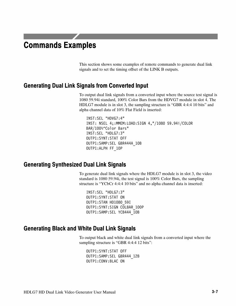
HDLG7 HD Dual Link Video Generator User Manual 3- 7
Commands Examples
This section shows some examples of remote commands to generate dual linksignals and to set the timing offset of the LINK B outputs.
Generating Dual Link Signals from Converted InputTo output dual link signals from a converted input where the source test signal is1080 59.94i standard, 100% Color Bars from the HDVG7 module in slot 4. TheHDLG7 module is in slot 3, the sampling structure is “GBR 4:4:4 10 bits” andalpha channel data of 10% Flat Field is inserted:
INST:SEL HDVG7:4"INST: NSEL 4;:MMEM:LOAD:SIGN 4,"/1080 59.94i/COLORBAR/100%^Color Bars"INST:SEL HDLG7:3"OUTP1:SYNT:STAT OFFOUTP1:SAMP:SEL GBR444A_10BOUTP1:ALPH FF_10P
Generating Synthesized Dual Link SignalsTo generate dual link signals where the HDLG7 module is in slot 3, the videostandard is 1080 59.94i, the test signal is 100% Color Bars, the samplingstructure is “YCbCr 4:4:4 10 bits” and no alpha channel data is inserted:
INST:SEL HDLG7:3"OUTP1:SYNT:STAT ONOUTP1:STAN HD1080_59IOUTP1:SYNT:SIGN COLBAR_100POUTP1:SAMP:SEL YCB444_10B
Generating Black and White Dual Link SignalsTo output black and white dual link signals from a converted input where thesampling structure is “GBR 4:4:4 12 bits”:
OUTP1:SYNT:STAT OFFOUTP1:SAMP:SEL GBR444_12BOUTP1:CONV:BLAC ON
Syntax
3- 8 HDLG7 HD Dual Link Video Generator User Manual
Setting Timing Offset of Link B Relative to Link ATo set the timing offset of the LINK B outputs to 0.0269 ms from the LINK Aoutputs:
SENS1:CORR:MDEL:HOR 0.0269

Appendices


HDLG7 HD Dual Link Video Generator User Manual A- 1
Appendix A: Specifications
Tables A--1 through A--8 list the electrical, mechanical, and environmentalcharacteristics of the HDLG7 module.
Electrical Characteristics
Table A- 1: 4:2:2 serial digital video signal input
Characteristic Description
Number of inputs 1
Format Compatible with SMPTE 292M. See Table A--6 for supported input and output formats.
Input type 75Ω BNC
Cable loss accommodation 0--20 dB attenuation with 1/SQRT(f) characteristic at 1/2 of serial rate.
Launch amplitude accommodation,typical
800 mV± 10% for full specification800 mV± 30% up to 20 dB cable attenuation
Jitter tolerance, typical 0.35± 0.1 UI p-p above 1 MHz. Increases proportional to 1/f below 1 MHz.
Return loss ≥15 dB, 5 MHz to 750 MHz≥10 dB, 750 MHz to 1.485 GHz
Table A- 2: Dual link serial video outputs
Characteristic Description
Number of outputs 2 on each channel (link)
Format Compatible with SMPTE 372M and SMPTE 292M
Output type 75Ω BNC
Output level 800 mV± 10%
Rise and fall times 270 ps max. (20% to 80%)
Jitter, typical 135 ps max. (0.2 UI alignment jitter)
Return loss ≥15 dB, 5 MHz to 750 MHz≥10 dB, 750 MHz to 1.485 GHz

Appendix A: Specifications
A- 2 HDLG7 HD Dual Link Video Generator User Manual
Table A- 3: Video signal content
Characteristic Description
Conversion accuracy, typical 0.4%
Accuracy of synthesizer generated testsignals, typical
0.2%
Timing offset of Link B in reference toLink A
±200 ns min. Adjustment in steps of the clock period (13.5 ns)
Table A- 4: Synthesizer generator test signals
Characteristic Description
Color Bars 100% Color Bars, 75% Color Bars, SMPTE HD/SD Compatible1
Linearity Ramp, Valid Ramp, 5 Step Staircase
Flat Field 0% Flat Field, 10% Flat Field, 20% Flat Field, 30% Flat Field, 40% Flat Field,50% Flat Field, 60% Flat Field, 70% Flat Field, 80% Flat Field, 90% Flat Field,100% Flat Field
Monitor 100% Red Field, 75% Red Field, 100% Blue Field, 75% Blue Field, 100% Green Field,75% Green Field, Convergence
Pulse bar 2T30 Pulse and Bar
1 SMPTE HD/SD Compatible refers to SMPTE RP219 Color Bar (I/Q Even).
Table A- 5: Embedded audio and ancillary data
Characteristic Description
Embedded audio Embedded audio on 4:2:2 video input is placed on the Link A video outputs as perSMPTE 372M.
Ancillary data Embedded ancillary data on 4:2:2 video input is placed on the Link A video outputs as perSMPTE 372M.

Appendix A: Specifications
HDLG7 HD Dual Link Video Generator User Manual A- 3
Table A- 6: Supported input and output formats (SMPTE 274M to SMPTE 372M standards)
Input format (4:2:2 YCbCr/10 bit) Format selection of dual link output
1920 X 1080i 50 Hz 4:2:2 (YCbCr)/10 bit 1920 X 1080p 50Hz
4:4:4 (YCbCr), 4:4:4:4 (YCbCrA)/10 bit 1920 X 1080i 50 Hz
4:4:4 (YCbCr)/12 bit 1920 X 1080i 50 Hz
4:4:4 (RGB), 4:4:4:4 (RGBA)/10 bit 1920 X 1080i 50 Hz
4:4:4 (RGB)/12 bit 1920 X 1080i 50 Hz
4:2:2 (YCbCr), 4:2:2:4 (YCbCrA)/12 bit 1920 X 1080i 50 Hz
1920 X 1080i 60/59.94 Hz 4:2:2 (YCbCr)/10 bit 1920 X 1080p 60/59.94Hz/
4:4:4 (YCbCr), 4:4:4:4 (YCbCrA)/10 bit 1920 X 1080i 60/59.94 Hz
4:4:4 (YCbCr)/12 bit 1920 X 1080i 60/59.94 Hz
4:4:4 (RGB), 4:4:4:4 (RGBA)/10 bit 1920 X 1080i 60/59.94 Hz
4:4:4 (RGB)/12 bit 1920 X 1080i 60/59.94 Hz
4:2:2 (YCbCr), 4:2:2:4 (YCbCrA)/12 bit 1920 X 1080i 60/59.94 Hz
1920 X 1080p/PsF 30/29.97 Hz 4:4:4 (YCbCr), 4:4:4:4 (YCbCrA)/10 bit 1920 X 1080p/PsF 30/29.97 Hzp/ /
4:4:4 (YCbCr)/12 bit 1920 X 1080p/PsF 30/29.97 Hz
4:4:4 (RGB), 4:4:4:4 (RGBA)/10 bit 1920 X 1080p/PsF 30/29.97 Hz
4:4:4 (RGB)/12 bit 1920 X 1080p/PsF 30/29.97 Hz
4:2:2 (YCbCr), 4:2:2:4 (YCbCrA)/12 bit 1920 X 1080p/PsF 30/29.97 Hz
1920 X 1080p/PsF 25 Hz 4:4:4 (YCbCr), 4:4:4:4 (YCbCrA)/10 bit 1920 X 1080p/PsF 25 Hzp/
4:4:4 (YCbCr)/12 bit 1920 X 1080p/PsF 25 Hz
4:4:4 (RGB), 4:4:4:4 (RGBA)/10 bit 1920 X 1080p/PsF 25 Hz
4:4:4 (RGB)/12 bit 1920 X 1080p/PsF 25 Hz
4:2:2 (YCbCr), 4:2:2:4 (YCbCrA)/12 bit 1920 X 1080p/PsF 25 Hz
1920 X 1080p/PsF 24/23.98 Hz 4:4:4 (YCbCr), 4:4:4:4 (YCbCrA)/10 bit 1920 X 1080p/PsF 24/23.98 Hzp/ /
4:4:4 (YCbCr)/12 bit 1920 X 1080p/PsF 24/23.98 Hz
4:4:4 (RGB), 4:4:4:4 (RGBA)/10 bit 1920 X 1080p/PsF 24/23.98 Hz
4:4:4 (RGB)/12 bit 1920 X 1080p/PsF 24/23.98 Hz
4:2:2 (YCbCr), 4:2:2:4 (YCbCrA)/12 bit 1920 X 1080p/PsF 24/23.98 Hz

Appendix A: Specifications
A- 4 HDLG7 HD Dual Link Video Generator User Manual
Mechanical Characteristics
Table A- 7: Mechanical characteristics
Characteristic Description
Dimensions
Height 41.5 mm (1.63 in)
Width 78.4 mm (3.1 in)
Depth 394 mm (15.5 in)
Weight 340 g (0.75 lb)
Environmental Characteristics
Table A- 8: Environmental characteristics
Characteristic Description
Temperature
Operating 0_ C to +50_ C
Non-operating --20_ C to +60_ C
Relative Humidity
Operating 20 % to 80 % (No condensation); Maximum wet-bulb temperature 29.4_ C
Non-operating 5 % to 90 % (No condensation); Maximum wet-bulb temperature 40.0_ C
Altitude
Operating To 4.5 km (15,000 feet)Maximum operating temperature decreases 1_ C each 300 m above 1.5 km.
Non-operating To 15 km (50,000 feet)
Vibration
Operating 3.04 m/s2 (0.31 Grms), 5 Hz to 500 Hz, 10 min, three axes
Non-operating 23.3 m/s2 (2.38 Grms), 5 Hz to 500 Hz, 10 min, three axes
Shock
Non-operating 294 m/s2 (30 G), half-sine, 11 ms duration

Index


HDLG7 HD Dual Link Video Generator User Manual Index- 1
IndexAAccessoriesoptional, 1--2standard, 1--2
CCommandsRules for forming, 3--1Syntax, 3--1
Commands examples, 3--7
EElectrical specifications, A--1Environmental specifications, A--4
FFactory default settings, 2--11Functional check, 1--2
HHD SDI IN connector, 2--10HDLG7 features, 1--1HDLG7 module main menu, 2--7Hierarchy (SCPI), 3--2
IInstallation, 1--2
LLINK A connectors, 2--10
LINK B connectors, 2--10LINK OFFSET submenu, 2--9
MManuals, Related, iiiMechanical specifications, A--4
OOperating procedure, 2--1Option, 1--2Optional accessories, 1--2OUTPUT commands, 3--3
PProduct description, 1--1
RRear-panel connectors, 2--10Related Manuals, iiiRemote commands, 3--3Rules, Command forming, 3--1
SSCPI, Subsystem hierarchy tree, 3--2SCPI commands and queries syntax, 3--1–3--2SENSE commands, 3--6Signal set assigned to the test signal buttons, 2--4SpecificationsElectrical, A--1Environmental, A--4
Standard accessories, 1--2Syntax, Command, 3--1

Index
Index- 2 HDLG7 HD Dual Link Video Generator User Manual


User Manual
HDVG7HDTV Digital Video Generator
www.tektronix.com

Copyright © Tektronix. All rights reserved. Licensed software products are owned by Tektronix or its suppliers and areprotected by United States copyright laws and international treaty provisions.
Tektronix products are covered by U.S. and foreign patents, issued and pending. Information in this publication supercedesthat in all previously published material. Specifications and price change privileges reserved.
TEKTRONIX and TEK are registered trademarks of Tektronix, Inc.
Contacting Tektronix
Tektronix, Inc.14200 SW Karl Braun DriveP.O. Box 500Beaverton, OR 97077USA
For product information, sales, service, and technical support:H In North America, call 1-800-833-9200.H Worldwide, visit www.tektronix.com to find contacts in your area.

HDVG7 HDTV Digital Video Generator User Manual i
Table of Contents
Preface iii. . . . . . . . . . . . . . . . . . . . . . . . . . . . . . . . . . . . . . . . . . . . . . . . . . .About This Manual iii. . . . . . . . . . . . . . . . . . . . . . . . . . . . . . . . . . . . . . . . . . . . . . .Related Manuals iii. . . . . . . . . . . . . . . . . . . . . . . . . . . . . . . . . . . . . . . . . . . . . . . . .
Getting StartedProduct Description 1--1. . . . . . . . . . . . . . . . . . . . . . . . . . . . . . . . . . . . . . . . . . . . . .Accessories 1--2. . . . . . . . . . . . . . . . . . . . . . . . . . . . . . . . . . . . . . . . . . . . . . . . . . . . .Options 1--2. . . . . . . . . . . . . . . . . . . . . . . . . . . . . . . . . . . . . . . . . . . . . . . . . . . . . . . .Installation 1--3. . . . . . . . . . . . . . . . . . . . . . . . . . . . . . . . . . . . . . . . . . . . . . . . . . . . .Functional Check 1--3. . . . . . . . . . . . . . . . . . . . . . . . . . . . . . . . . . . . . . . . . . . . . . . .
Operating BasicsOperating Procedure 2--1. . . . . . . . . . . . . . . . . . . . . . . . . . . . . . . . . . . . . . . . . . . . . .Selecting an Output Signal 2--2. . . . . . . . . . . . . . . . . . . . . . . . . . . . . . . . . . . . . . . . .HDVG7 Module Main Menu 2--4. . . . . . . . . . . . . . . . . . . . . . . . . . . . . . . . . . . . . . .Rear-Panel Connectors 2--18. . . . . . . . . . . . . . . . . . . . . . . . . . . . . . . . . . . . . . . . . . . .Factory Default Settings 2--19. . . . . . . . . . . . . . . . . . . . . . . . . . . . . . . . . . . . . . . . . . .
ReferenceSyntax 3--1. . . . . . . . . . . . . . . . . . . . . . . . . . . . . . . . . . . . . . . . . . . . . . . . . . .Programming Model 3--1. . . . . . . . . . . . . . . . . . . . . . . . . . . . . . . . . . . . . . . . . . . . . .SCPI Commands and Queries 3--3. . . . . . . . . . . . . . . . . . . . . . . . . . . . . . . . . . . . . .
Remote Commands 3--5. . . . . . . . . . . . . . . . . . . . . . . . . . . . . . . . . . . . . . . .MASS MEMORY Commands 3--5. . . . . . . . . . . . . . . . . . . . . . . . . . . . . . . . . . . . . .OUTPUT Commands 3--6. . . . . . . . . . . . . . . . . . . . . . . . . . . . . . . . . . . . . . . . . . . . .SENSE Commands 3--15. . . . . . . . . . . . . . . . . . . . . . . . . . . . . . . . . . . . . . . . . . . . . . .
AppendicesAppendix A: Specifications A--1. . . . . . . . . . . . . . . . . . . . . . . . . . . . . . . . . .Electrical Characteristics A--1. . . . . . . . . . . . . . . . . . . . . . . . . . . . . . . . . . . . . . . . . .Environmental Characteristics A--2. . . . . . . . . . . . . . . . . . . . . . . . . . . . . . . . . . . . . .
Index

Table of Contents
ii HDVG7 HDTV Digital Video Generator User Manual
List of Figures
Figure 2--1: Front-panel test signal buttons 2--3. . . . . . . . . . . . . . . . . . . .Figure 2--2: HDVG7 module main menu 2--4. . . . . . . . . . . . . . . . . . . . . . .Figure 2--3: MOVING PICTURE submenu 2--6. . . . . . . . . . . . . . . . . . . .Figure 2--4: OVERLAY submenu 2--7. . . . . . . . . . . . . . . . . . . . . . . . . . . .Figure 2--5: LOGO submenu 2--8. . . . . . . . . . . . . . . . . . . . . . . . . . . . . . . .Figure 2--6: ID TEXT submenu 2--9. . . . . . . . . . . . . . . . . . . . . . . . . . . . . .Figure 2--7: CIRCLE submenu 2--10. . . . . . . . . . . . . . . . . . . . . . . . . . . . . .Figure 2--8: AUDIO GROUP submenu 2--12. . . . . . . . . . . . . . . . . . . . . . . .Figure 2--9: AUDIO CHANNEL submenu 2--13. . . . . . . . . . . . . . . . . . . . .Figure 2--10: TIMING submenu 2--15. . . . . . . . . . . . . . . . . . . . . . . . . . . . . .Figure 2--11: VIDEO submenu 2--16. . . . . . . . . . . . . . . . . . . . . . . . . . . . . . .Figure 2--12: BLACK submenu (Option BK only) 2--17. . . . . . . . . . . . . . .Figure 2--13: HDVG7 module rear-panel connectors (Option BK) 2--19.Figure 3--1: Example of SCPI subsystem hierarchy 3--3. . . . . . . . . . . . . .
List of Tables
Table 1--1: Standard and optional accessories 1--2. . . . . . . . . . . . . . . . . .Table 2--1: Signal set assigned to the test signal buttons 2--3. . . . . . . . . .Table 2--2: Factory default settings 2--19. . . . . . . . . . . . . . . . . . . . . . . . . .Table A--1: Serial digital video signal outputs A--1. . . . . . . . . . . . . . . . .Table A--2: Serial digital black signal outputs (Option BK only) A--1. .Table A--3: Embedded audio A--2. . . . . . . . . . . . . . . . . . . . . . . . . . . . . . .Table A--4: Environmental characteristics A--2. . . . . . . . . . . . . . . . . . . . .

HDVG7 HDTV Digital Video Generator User Manual iii
Preface
This manual documents the capabilities, operation, and specifications of theHDVG7 HDTV Digital Video Generator module.
About This ManualThis manual is composed of the following sections:
H Getting Started contains product description and functional check procedure.
H Operating Basics explains how to operate the HDVG7 module using themenus and front-panel buttons.
H Reference provides the syntax used in command descriptions and describesall programming commands.
H Appendices provides the specifications.
Related ManualsThe following documents are also available.
H The TG700 TV Signal Generator Platform Service Manual (Tektronix partnumber 070-A800-XX) describes how to maintain and service the mainframeand generator modules. This manual is an optional accessory.
H The TG700 TV Signal Generator Platform Module Installation Instructions(Tektronix part number 070-A824-XX) describes how to install and removethe modules, and how to upgrade the firmware of the mainframe.

Preface
iv HDVG7 HDTV Digital Video Generator User Manual

Getting Started


HDVG7 HDTV Digital Video Generator User Manual 1- 1
Getting Started
This section contains the following information:
H Product description
H Accessories
H Options
H Installation
H Functional check
Product DescriptionThe HDVG7 HDTV Digital Video Generator module is designed to be installedin the TG700 TV Signal Generator Platform.
The module is an HDTV test signal generator which provides 1.485 Gb/s serialdigital video signals in various formats. The module contains the followingfeatures:
H Two serial digital video outputs
H Two serial digital black outputs (option BK)
H Supports SMPTE 274M (1080), SMPTE 240M (1035), and SMPTE 296M(720)
H Overlay of circle, text, or logo on the video signal
H Generates a moving picture by scrolling the active picture area of the outputtest signal
H Up to 16 channels of Embedded Audio
H Full remote control using Ethernet interface
The module can generate video signals with 24 (or 20) bit embedded digitalaudio with a sample rate of 48 kHz.

Getting Started
1- 2 HDVG7 HDTV Digital Video Generator User Manual
The following audio frequencies are supported.
Silence 500 Hz 2000 Hz 8000 Hz50 Hz 600 Hz 2400 Hz 9600 Hz100 Hz 750 Hz 3000 Hz 10000 Hz150 Hz 800 Hz 3200 Hz 12000 Hz200 Hz 1000 Hz 4000 Hz 15000 Hz250 Hz 1200 Hz 4800 Hz 16000 Hz300 Hz 1500 Hz 5000 Hz 20000 Hz400 Hz 1600 Hz 6000 Hz
AccessoriesTable 1--1 lists the standard and optional accessories provided with the HDVG7Generator module.
Table 1- 1: Standard and optional accessories
Accessory Std. Opt.Tektronixpart number
TG700 TV Signal Generator Platform Module InstallationInstructions
D 070-A824-XX
TG700 Signal Generator Platform Software Library CD-ROM D 062-A249-XX
TG700 TV Signal Generator Platform Service Manual D 070-A800-XX
OptionsThis subsection describes the options available for the HDVG7 Generatormodule. The following options are available:
Option BK (Serial digital black output)
Option D1 (Test data report)
Two serial digital black signal outputs are added to the HDVG7 Generatormodule when this option is specified.
A calibration test data report will be provided with the HDVG7 Generatormodule when this option is specified.
Option BK (Serial DigitalBlack Output)
Option D1 (Test DataReport)

Getting Started
HDVG7 HDTV Digital Video Generator User Manual 1- 3
InstallationRefer to the TG700 TV Signal Generator Platform Module InstallationInstructions for instructions on how to install the HDVG7 Generator module.
Functional CheckThe following procedure determines whether the module is operating correctly.
The following equipment is required for the functional check:
H HDTV waveform monitor
H 75 Ω BNC cable
1. Install the module into the TG700 Platform mainframe using the installationprocedures described in the TG700 TV Signal Generator Platform UserManual.
2. Power on the TG700 TV Signal Generator Platform by connecting it to thepower source. The initialization of all the installed modules is executed.
3. Check that no error messages appear on the LCD display.
4. Warm up the instrument for 20 minutes.
5. Press the front-panelMODULE button until the HDVG7 main menu shownbelow appears.
HDVG7 [x] : STATUS : 1080 59.94i100% Color Bars
6. Press the FORMAT button and use the left (A) or right (") arrow button toselect a format, then press the ENTER button.
7. Press one of the front-panel test signal button (for example COLOR BAR)to output a signal.
8. Connect the SIGNAL 1 connector to the HDTV waveform monitor usingthe 75 Ω BNC cable.
9. Set the waveform monitor to view the signal.
10. Check that the signal appears as expected. For example, if you selected acolor bar signal in step 7, check that the color bar signal appears.
Required equipment
Procedure

Getting Started
1- 4 HDVG7 HDTV Digital Video Generator User Manual
11. Disconnect the BNC cable from the SIGNAL 1 connector, and then connectthe BNC cable to the SIGNAL 2 connector.
12. Check that the signal appears as expected.

Operating Basics


HDVG7 HDTV Digital Video Generator User Manual 2- 1
Operating Basics
This section explains the operation of the HDVG7 Generator module using thefront-panel buttons and menus. It also contains descriptions of the rear-panelconnectors.
Refer to the TG700 TV Signal Generator Platform User Manual for a detailedexplanation of the front-panel buttons and the LCD display.
Operating ProcedureAfter the module is installed in the mainframe, and the mainframe is installed inthe rack or other location where it will be used, access each function of themodule with the following procedure:
1. Connect the power connector on the rear panel to the AC electric powersource using the power cord.
Electric power is supplied to the mainframe.
2. Wait until the power up initialization process is complete, and check that noerror messages appear on the display.
3. Following the initialization process the mainframe main menu appears, asshown below.
TG700 : PRESET
4. Press the front-panelMODULE button until the HDVG7 module mainmenu appears, as shown below.
HDVG7 [x] : STATUS : 1080 59.94i100% Color Bars
5. Select the signal format and the signal you want to output. Refer to Selectingan Output Signal on page 2--2 for more information.
6. Press the front-panel arrow buttons to select the desired main menu item orsubmenu.
Refer to HDVG7 Module Main Menu beginning on page 2--4 for detailedinformation about the main menu items and the submenu items.

Operating Basics
2- 2 HDVG7 HDTV Digital Video Generator User Manual
Selecting an Output SignalWhen you output a signal from the HDVG7 Generator module, you need toselect a signal format and output signal. This subsection provides instructions onhow to output a signal.
If you press the front-panel FORMAT button when the HDVG7 Generatormodule is selected (active), you can select the format for the output signals.
Perform the following steps to select the format:
1. Confirm that any menu item of the HDVG7 module main menu is displayed.If the menu is not displayed, press the front-panelMODULE button untilthe HDVG7 module main menu appears, as shown below.
HDVG7 [x] : STATUS : 1080 59.94i100% Color Bars
2. Press the FORMAT button. The menu display changes as follows:
HDVG7 [x] : SELECT FORMAT1080 59.94i (Current)
3. Press the left (A) or right (") arrow button to select one of the signalformats, and then press the ENTER button to confirm the selection.
NOTE. When you change signal format, synchronization shock occurs.
All signal sets available in the module are already assigned to the correspondingtest signal buttons (see Figure 2--1). When you press any of the buttons, one ofthe signals in the signal set is output.
For example, when you press the COLOR BAR test signal button, you canoutput the 100% Color Bars signal in the Color Bars signal set.
Press the left (A) or right (") arrow button, or press the test signal buttonrepeatedly to select different signals assigned to the test signal button.
Selecting a Format
Selecting a Signal

Operating Basics
HDVG7 HDTV Digital Video Generator User Manual 2- 3
Test signal buttons
Figure 2- 1: Front-panel test signal buttons
Table 2--1 lists the signal set assigned to each test signal button and the signalsthat can be selected in the signal set.
Table 2- 1: Signal set assigned to the test signal buttons
Button name Signal set Signals in the signal set
COLOR BAR Color Bars 100% Color Bars, 75% Color Bars,SMPTE Color Bars
LINEARITY Linearity 5 Step Staircase, Limit Ramp, Ramp,Shallow Ramp Matrix, Shallow RampValid Ramp
FLAT FIELD Flat Fields 0% Flat Field, 50% Flat Field, 100% Flat Field
MULTI BURST Multi Burst Multiburst 1--10 MHz, Multiburst 10--20 MHz,Multiburst 20--30 MHz
SWEEP Sweep 100% Sweep 1--15 MHz,100% Sweep 1--30 MHz
MONITOR Monitor 75% Blue Field, 75% Green Field,75% Red Field, Convergence
PULSE BAR Pulse & Bar 2T30 Pulse and Bar
TIMING Timing Bowtie 1ns Markers, Co-site Pulse
SDI SDI Test Equalizer Test, PLL Test, SDI Matrix
OTHER ------ -- -- -- -- -- -- -- -- --
If you want to output custom signals from the module, you need to assign thesignal set to any of the test signal buttons. Refer to TG700 TV Signal GeneratorPlatform User Manual for detailed information about how to assign a signal setto a test signal button.

Operating Basics
2- 4 HDVG7 HDTV Digital Video Generator User Manual
HDVG7 Module Main MenuYou can set the logo, circle, and text overlay, embedded audio, timing offset ofthe serial digital signal outputs using the HDVG7 module main menu.
Use the up (Y) or down (B) arrow button to scroll through the main menu.Figure 2--2 shows the HDVG7 module main menu.
HDVG7 [x] : STATUS : 1080 59.94i100% Color Bars
HDVG7 [x] : TIMING
To AUDIO GROUP submenu(page 2--12)
ENTER
CANCEL
Selection by the MODULE button
HDVG7 [x] : MOVING PICTURE
HDVG7 [x] : OVERLAY
HDVG7 [x] : AUDIO (EMBEDDED)Group 1
To OVERLAY submenu(page 2--8)
ENTER
CANCEL
To MOVING PICTURE submenu(page 2--6)
ENTER
CANCEL
To TIMING submenu(page 2--15)
ENTER
CANCEL
To VIDEO submenu(page 2--16)
ENTER
CANCEL
HDVG7 [x] : VIDEO
Group 1Group 2Group 3Group 4
To BLACK submenu(page 2--17)
ENTER
CANCEL
HDVG7 [x] : BLACK (OPTION)
Option BK only
Figure 2- 2: HDVG7 module main menu

Operating Basics
HDVG7 HDTV Digital Video Generator User Manual 2- 5
MOVING PICTURE. Scrolls the active picture area of the output test signal. Whenyou select this menu item and then press the ENTER button, you will access theMOVING PICTURE submenu. Refer to MOVING PICTURE Submenu on page2--6 for detailed information.
OVERLAY. Selects an item (logo, text, or circle) that is overlaid on the output testsignal and sets the blinking mode for the overlay. When you select this menuitem and then press the ENTER button, you will access the OVERLAYsubmenu. Refer to OVERLAY Submenu on page 2--7 for detailed information.
AUDIO (EMBEDDED). Sets the parameters for embedded audio on the output testsignals. Use the left (A) or right (") arrow button to select Group 1, Group 2,Group 3, or Group 4. When you select any of the items and then press theENTER button, you will access the AUDIO GROUP submenu. Refer to AUDIOGROUP Submenu on page 2--12 for detailed information.
TIMING. Sets the timing offset of the serial digital video outputs relative to theinternal reference signal (frame reset signal). When you select this menu itemand then press the ENTER button, you will access the TIMING submenu. Referto TIMING Submenu on page 2--15 for detailed information.
VIDEO. Enables or disables the Y, Pb, or Pr component of the output serialdigital video signals and the output mode fot an audio/video timing measeure-ment. When you select this menu item and then press the ENTER button, youwill access the VIDEO submenu. Refer to VIDEO Submenu on page 2--16 fordetailed information.
BLACK (OPTION). This menu is only available Option BK, and sets the parame-ters of the serial digital black signals output from the BLACK 1 and BLACK 2connectors. When you select this menu item and then press the ENTER button,you will access the BLACK submenu. Refer to BLACK Submenu on page 2--17for detailed information.

Operating Basics
2- 6 HDVG7 HDTV Digital Video Generator User Manual
This menu allows you to scroll the active picture area of the serial digital videosignal up/down or left/right (or randomly). Use the up (Y) or down (B) arrowbutton to scroll through the menu. Figure 2--3 shows the MOVING PICTUREsubmenu.
HDVG7 [x] : MOVING PICTUREH Step : 0 Sample (s)
HDVG7 [x] : MOVING PICTUREV Step : 0 Line (s)
HDVG7 [x] : MOVING PICTUREPeriod : 1 Frame (s)
Select MOVING PICTUREin the main menu
HDVG7 [x] : MOVING PICTURERandom : Disable
DisableEnable
Set the line number to be scrolled
Set the frame period to be scrolled
Set the sample number to be scrolled
Figure 2- 3: MOVING PICTURE submenu
H H Step: Sets the number of samples to be scrolled per frame set in thePeriod menu item. Use the left (A) or right (") arrow button to change thevalue. You can set the value from --252 to +252 in 4 samples steps.
H V Step: Sets the number of lines to be scrolled per frame set in the Periodmenu item. Use the left (A) or right (") arrow button to change the value.You can set the value from --252 to +252 in 1 line steps.
H Period: Sets the time interval between occurrences of the scrolling. Use theleft (A) or right (") arrow button to change the value. You can set the valuefrom 1 to 16 in 1 frame steps.
H Random: Sets whether or not the picture scrolls randomly. Use the left (A)or right (") arrow button to select between Disable and Enable. Press theENTER button to confirm the selection.
MOVING PICTURESubmenu

Operating Basics
HDVG7 HDTV Digital Video Generator User Manual 2- 7
This menu allows you to select an item (logo, ID Text, or circle) to overlay onthe output test signal, and to set the blinking mode for the overlay. Use the up(Y) or down (B) arrow button to scroll through the menu. Figure 2--4 shows theOVERLAY submenu.
HDVG7 [x] : OVERLAY : OBJECTLogo
Select OVERLAYin the main menu
HDVG7 [x] : OVERLAY : BLINKOFF
OFFFastSlow
To LOGO submenu (page 2--8)To ID TEXT submenu (page 2--9)To CIRCLE submenu (page 2--10)
ENTER
CANCEL
LogoID TextCircle
Figure 2- 4: OVERLAY submenu
H OBJECT: Selects an item that is overlaid on the output test signal. Use theleft (A) or right (") arrow button to select Logo, ID Text, or Circle. Whenyou select any of these items and then press the ENTER button, you willaccess the submenu for setting that overlay. Refer to LOGO Submenu onpage 2--8, ID TEXT Submenu on page 2--9, or CIRCLE Submenu on page2--10 for detailed information.
H BLINK: Sets the blinking mode for the overlay. Use the left (A) or right(") arrow button to select OFF, Fast (blinks approximately at 0.5 secondinterval), or Slow (blinks approximately at 1.0 interval). Press the ENTERbutton to confirm the selection.
OVERLAY Submenu

Operating Basics
2- 8 HDVG7 HDTV Digital Video Generator User Manual
This menu allows you to select a logo to overlay on the output test signal, and toset the display position of the logo. Use the up (Y) or down (B) arrow button toscroll through the menu. Figure 2--5 shows the LOGO submenu.
HDVG7 [x] : OVERLAY : LOGOX Position : 0.0 % APH
Select OFF or a logo
HDVG7 [x] : OVERLAY : LOGOY Position : 0.0 % APH
HDVG7 [x] : OVERLAY : LOGOLogo : OFF
Select Logo in theOVERLAY submenu
Set the horizontal position
Set the vertical position
HDVG7 [x] : OVERLAY : LOGO : SAVEPress ENTER to save parameters
ENTERSave the display position for the logo
Figure 2- 5: LOGO submenu
H Logo: Selects the logo you want to display. Use the left (A) or right (")arrow button to select OFF or a logo file name. Press the ENTER buttonconfirm the selection. When you select OFF, the logo overlay is disabled.
H X Position: Sets the horizontal position of the logo. The position is set as apercentage of active picture width. Use the left (A) or right (") arrow buttonto change the position. You can set the value from --100.0 % to 0.0 % in0.1% steps.
H Y Position: Sets the vertical position of the logo. The position is set as apercentage of active picture height. Use the left (A) or right (") arrowbutton to change the position. You can set the value from --100.0 % to 0.0 %in 0.1% steps.
H SAVE: Saves the display position for the logo to the logo file. Press theENTER button to save the current settings.
In order to display a logo using the LOGO submenu, you need to create the logofile (.lgo) and download it to the LOGO folder of the module.
LOGO Submenu

Operating Basics
HDVG7 HDTV Digital Video Generator User Manual 2- 9
Refer to the TG700 TV Signal Generator Platform User Manual for detailedinformation about how to create a logo file and download it to the TG700.
This menu allows you to edit a text overlaid on the output test signal, and to setthe display position of the text. Use the up (Y) or down (B) arrow button tochange the menu items. Figure 2--6 shows the ID TEXT submenu.
HDVG7 [x] : OVERLAY : TEXTStatus : Enable
Edit text
HDVG7 [x] : OVERLAY : TEXTX Position : 0.0 % APH
HDVG7 [x] : OVERLAY : TEXT : EDIT_
Set the horizontal position
Set the vertical positionHDVG7 [x] : OVERLAY : TEXTY Position : 0.0 % APH
DisableEnable
HDVG7 [x] : OVERLAY : TEXT : SAVE ENTERSave the text to the signal file
Select ID Text in theOVERLAY submenu
ENTER
Figure 2- 6: ID TEXT submenu
H Status : Enables or disables the text overlay. Use the left (A) or right (")arrow button to select between Enable and Disable. Press the ENTERbutton to confirm the selection.
H X Position: Sets the horizontal position of the text. The position is set as apercentage of active picture width. Use the left (A) or right (") arrow buttonto change the position. You can set the value from 0.0 % to 100.0 % in 1%steps.
ID TEXT Submenu

Operating Basics
2- 10 HDVG7 HDTV Digital Video Generator User Manual
H Y Position: Sets the vertical position of the text. The position is set as apercentage of active picture height. Use the left (A) or right (") arrowbutton to change the position. You can set the value from 0.0 % to 100.0 %in 1% steps.
H EDIT: Edits the text you want to display on the output test signal.
To edit the text, first press the ENTER button to enable the text edit mode.Use the left (A) or right (") arrow button to move the underscore character( _ ) to the character you want to change, then use the up (Y) or down (B)arrow button to select the desired character. When you have entered all of thedesired characters, press the ENTER button to end the text editing process.You can use up to 30 characters for the text. Use the blank character to erasean unneeded character(s).
H SAVE: Saves the text and its position to the signal file currently beingoutput. Press the ENTER button to save the text and its position to thesignal file.
This menu allows you to create a circle overlaid on the output test signal and setthe display position of the circle. Use the up (Y) or down (B) arrow button tochange the menu items. Figure 2--7 shows the CIRCLE submenu.
HDVG7 [x] : OVERLAY : CIRCLEStatus : Enable
Set the diameter of the circle
HDVG7 [x] : OVERLAY : CIRCLEX Position : 0.0 % APH
HDVG7 [x] : OVERLAY : CIRCLEDiameter : 10.0 % APH
Set the horizontal position
Set the vertical positionHDVG7 [x] : OVERLAY : CIRCLEY Position : 0.0 % APH
DisableEnable
Select Circle in theOVERLAY submenu
Figure 2- 7: CIRCLE submenu
CIRCLE Submenu

Operating Basics
HDVG7 HDTV Digital Video Generator User Manual 2- 11
H Status : Enables or disables the circle overlay. Use the left (A) or right (")arrow button to select between Enable and Disable. Press the ENTERbutton to confirm the selection.
H X Position: Sets the horizontal position of the circle. The position is set as apercentage of active picture width. Use the left (A) or right (") arrow buttonto change the position. You can set the value from --50.0 % to 50.0 % in 1%steps.
H Y Position: Sets the vertical position of the circle. The position is set as apercentage of active picture height. Use the left (A) or right (") arrowbutton to change the position. You can set the value from --50.0 % to 50.0 %in 1% steps.
H Diameter: Sets the diameter of the circle. The diameter is set as a percentageof active picture height. Use the left (A) or right (") arrow button to changethe value. You can set the value from 0.0 % to 100.0 % in 1% steps.

Operating Basics
2- 12 HDVG7 HDTV Digital Video Generator User Manual
This menu allows you to enable or disable embedded audio of the selected audiogroup, select which audio channel to enable, and set the emphasis status bits,sampling alignment status bits, and sample bits of the selected audio group. Usethe up (Y) or down (B) arrow button to change the menu items. Figure 2--8shows the AUDIO GROUP submenu.
HDVG7 [x] : AUDIO : GRP--1Status : Enable
HDVG7 [x] : AUDIO : GRP--1Channel : 1
HDVG7 [x] : AUDIO : GRP--1Sampling : Frame
Select any of the audio groups in theAUDIO (EMBEDDED) main menu
NO EMPHASISCDCCITT
FrameFrame without Frame NumberAsynchronous
HDVG7 [x] : AUDIO : GRP--1Emphasis : NO EMPHASIS
1234
24 bits20 bits
To AUDIO CHANNEL submenu
ENTER
CANCEL
HDVG7 [x] : AUDIO : GRP--1Resolution : 24 bits
DisableEnable
Figure 2- 8: AUDIO GROUP submenu
H Status : Enables or disables the generation of embedded audio for theselected audio group. Use the left (A) or right (") arrow button to selectbetween Enable and Disable. Press the ENTER button to confirm theselection.
H Channel: Selects the channel you want to change the parameters. Use theleft (A) or right (") arrow button to select 1, 2, 3, or 4. When you select anyof the channels and then press the ENTER button to access the AUDIOCHANNEL submenu. Refer to AUDIO CHANNEL Submenu on page 2--13for detailed information about the menu.
AUDIO GROUP Submenu

Operating Basics
HDVG7 HDTV Digital Video Generator User Manual 2- 13
H Emphasis: Sets the emphasis status bits for the selected audio group. Usethe left (A) or right (") arrow button to select NO EMPHASIS, CD, orCCITT. Press the ENTER button to confirm the selection.
H Sampling: Sets the sampling alignment status bits for the selected audiogroup. Use the left (A) or right (") arrow button to select Frame, Framewithout Frame Number, or Asynchronous. Press the ENTER button toconfirm the selection.
H Resolution: Sets the resolution of the audio signal data for the selected audiogroup. Use the left (A) or right (") arrow button to select between 24 bitsand 20 bits. Press the ENTER button to confirm the selection.
This menu allows you to set the frequency, amplitude, and audio click of theembedded audio signal for the selected audio channel. Use the up (Y) or down(B) arrow button to scroll through the menu. Figure 2--9 shows the AUDIOCHANNEL submenu.
HDVG7 [x] : AUDIO : GRP--1 : CH--1Frequency : 1000 Hz
HDVG7 [x] : AUDIO : GRP--1 : CH--1Amplitude : --20.0 dBFS
--60 dBFS to 0 dBFS
Select any of the channels in the ChannelAUDIO GROUP submenu
HDVG7 [x] : AUDIO : GRP--1 : CH--1Audio Click : OFF
OFF1 sec2 sec3 sec4 sec
Inactive 300 Hz 1200 Hz 4000 Hz 12000 HzSilence 400 Hz 1500 Hz 4800 Hz 15000 Hz50 Hz 500 Hz 1600 Hz 5000 Hz 16000 Hz100 Hz 600 Hz 2000 Hz 6000 Hz 20000 Hz150 Hz 750 Hz 2400 Hz 8000 Hz200 Hz 800 Hz 3000 Hz 9600 Hz250 Hz 1000 Hz 3200 Hz 10000 Hz
Figure 2- 9: AUDIO CHANNEL submenu
AUDIO CHANNELSubmenu

Operating Basics
2- 14 HDVG7 HDTV Digital Video Generator User Manual
H Frequency : Sets the audio signal frequency of the selected audio channel.Use the left (A) or right (") arrow button to select the frequency. Theselection items are as follows:
Inactive 400 Hz 1600 Hz 6000 HzSilence 500 Hz 2000 Hz 8000 Hz50 Hz 600 Hz 24000 Hz 9600 Hz100 Hz 750 Hz 3000 Hz 10000 Hz150 Hz 800 Hz 3200 Hz 12000 Hz200 Hz 1000 Hz 4000 Hz 15000 Hz250 Hz 1200 Hz 4800 Hz 16000 Hz300 Hz 1500 Hz 5000 Hz 20000 Hz
When Inactive is selected, the audio data output is disabled. Press theENTER button to confirm the selection.
H Amplitude : Sets the audio signal amplitude of the selected audio channel.Use the left (A) or right (") arrow button to set the amplitude. You can setthe value from --60 dBFS to 0 dBFS in 1 dBFS steps.
H Audio Click : Inserts audio clicks in the selected audio channel. The audiotone, if any, is turned off for an interval around the audio click. Use the left(A) or right (") arrow button to make the selection. The choices are OFF,1 sec, 2 sec, 3 sec, and 4 sec. Press the ENTER button to enable theselection.
Audio Click becomes valid when you select 1 sec to 4 sec for the AudioClick rate. When Audio Click is valid, Audio Tone is turned off for0.25 second around the click. For example, if you select 3 sec for the clickrate the audio tone will be output for 2.75 seconds, and silent for0.25 second; the click occurs during this silence. When Audio Click is OFF,the Audio Tone selected in the FREQUENCY menu is output continuously.Audio Click makes it easy to identify any channel(s) of the four outputchannels.

Operating Basics
HDVG7 HDTV Digital Video Generator User Manual 2- 15
This menu allows you to adjust the timing offset of the serial digital videooutputs relative to the internal reference signal (frame reset signal). Use the up(Y) or down (B) arrow button to change the menu items. Figure 2--10 shows theTIMING submenu.
HDVG7 [x] : TIMINGVertical : 0 Line(s)
HDVG7 [x] : TIMINGHorizontal : 0.0000 msec
Set the vertical timing
Select TIMINGin the main menu
Set the horizontal timing
Figure 2- 10: TIMING submenu
H Vertical: Sets the vertical timing offset. Use the left (A) or right (") arrowbutton to change the timing offset. You can set the value from --1/2 to +1/2frame in 1-line steps.
H Horizontal: Sets the horizontal timing offset. Use the left (A) or right (")arrow button to change the timing offset. You can set the value from --1 to +1line in 1-clock (13.5 ns) steps.
NOTE. You can reset the timing offset to zero by pressing the left (A) and right(") arrow buttons simultaneously.
TIMING Submenu

Operating Basics
2- 16 HDVG7 HDTV Digital Video Generator User Manual
This menu allows you to turn the Y, Pb, or Pr component of the serial digitalvideo signals on or off individually. You can also turn the output mode for anaudio/video timing measurement on or off. Use the up (Y) or down (B) arrowbutton to scroll through the menu. Figure 2--11 shows the VIDEO submenu.
HDVG7 [x] : VIDEOY : ON
HDVG7 [x] : VIDEOPb : ON
ONOFF
Select VIDEO in the main menu
HDVG7 [x] : VIDEOPr : ON
ONOFF
ONOFF
HDVG7 [x] : VIDEOAV Timing Mode : OFF
OFFON
Figure 2- 11: VIDEO submenu
H Y: Turns the Y component of the serial digital video signals on or off. Usethe left (A) or right (") arrow button to select between ON and OFF. Pressthe ENTER button to confirm the selection.
H Pb: Turns the Pb component of the serial digital video signals on or off. Usethe left (A) or right (") arrow button to select between ON and OFF. Pressthe ENTER button to confirm the selection.
H Pr: Turns the Pr component of the serial digital video signals on or off. Usethe left (A) or right (") arrow button to select between ON and OFF. Pressthe ENTER button to confirm the selection.
H AV Timing Mode: Turns the output mode for an audio/video timingmeasurement on or off. Use the left (A) or right (") arrow button to selectbetween ON and OFF. Press the ENTER button to confirm the selection.
VIDEO Submenu

Operating Basics
HDVG7 HDTV Digital Video Generator User Manual 2- 17
When you turn on this mode, the specified audio and video signals aresynchronously on for 0.5 second and off for 4.5 seconds. With this signal,you can measure the time delay that accumulates between the audio andvideo content of the television signal during signal transport. The time delaycan be measured by a video analyzer with the serial digital video signal or byan oscilloscope with the analog audio and video signals deembedded fromthe serial digital video signal. The following settings are recommended forthe audio and video signals when you use this mode:
Audio signal (CH1 and CH2 of Group 1) : 10000 Hz, --20 dBFSVideo signal: 100% Flat Field
NOTE. The AV Timing Mode setting is not saved as a preset.
This menu allows you to set the output parameters of the serial digital blacksignals output from the BLACK1 and BLACK 2 connectors. Use the up (Y) ordown (B) arrow button to scroll through the menu. Figure 2--12 shows theBLACK submenu.
HDVG7 [x] (BLACK) : FORMAT1080 60i
HDVG7 [x] (BLACK) : SIGNALBlack
HDVG7 [x] (BLACK) : AUDIO (EMBEDDED)Group 1
Select BLACK (OPTION )in the main menu
HDVG7 [x] (BLACK) : TIMING
Black 50% Flat Field40% Flat Field 100% Flat Field
Group 1Group 2Group 3Group 4
To AUDIO GROUP submenu
ENTER
CANCEL
To TIMING submenu
ENTER
CANCEL
1080 60i 1080 25p 720 50p1080 59.94i 1080 24p 720 30p1080 50i 1080 23.98p 720 29.97p1080 24sF 1035 60i 720 25p1080 23.98sF 1035 59.94i 720 24p1080 30p 720 60p 720 23.98p1080 29.97p 720 59.94p
Figure 2- 12: BLACK submenu (Option BK only)
BLACK Submenu(Option BK Only)

Operating Basics
2- 18 HDVG7 HDTV Digital Video Generator User Manual
FORMAT. Selects the format of the output serial digital black signals. Use the left(A) or right (") arrow button to select 1080 60i, 1080 59.94i, 1080 50i, 108024sF, 1080 30p, 1080 29.97p, 1080 25p, 1080 24p, 1080 23.98p, 1035 60i,1035 59.94i, 720 60p, 720 59.94p, 720 50p, 720 30p, 720 29.97p, 720 25p, 72024p, or 720 23.98p. Press the ENTER button to confirm the selection.
SIGNAL. Selects the serial digital black signal to output. Use the left (A) or right(") arrow button to select between Black (serial digital black), 40% Flat Field,50% Flat Field, and 100% Flat Field. Press the ENTER button to confirm theselection.
AUDIO (EMBEDDED). Sets the parameters for embedded audio on the serialdigital black signals. Use the left (A) or right (") arrow button to select Group1, Group 2, Group 3, or Group 4. When you select any of the groups and thenpress the ENTER button, you will access the AUDIO GROUP submenu. Referto AUDIO GROUP Submenu on page 2--12 for detailed information.
TIMING. Sets the timing offset of the serial digital black outputs relative to theinternal reference signal (frame reset signal). When you select this menu itemand then press the ENTER button, you will access the TIMING submenu. Referto TIMING Submenu on page 2--15 for detailed information.
Rear-Panel Connectors
CAUTION. If power is applied to the mainframe, be sure to connect a termina-tion(s) to the unused output(s).
The HDVG7 Generator module is equipped with two connectors, SIGNAL 1and SIGNAL 2, which will output serial digital test signals. If Option BK isinstalled there will be two additional connectors, BLACK 1 and BLACK 2,which will output serial digital black signals. Figure 2--13 shows the HDVG7Generator module rear-panel with all four connectors installed (Option BK).
NOTE. The SIGNAL 1 and SIGNAL 2 connectors will both output the same testsignal, and the BLACK 1 and BLACK 2 connectors will both output the sameblack signal.

Operating Basics
HDVG7 HDTV Digital Video Generator User Manual 2- 19
Figure 2- 13: HDVG7 module rear-panel connectors (Option BK)
H SIGNAL 1: Serial digital test signal output.
H SIGNAL 2: Serial digital test signal output.
H BLACK 1: Serial digital black output (Option BK only).
H BLACK 2: Serial digital black output (Option BK only).
Factory Default SettingsTable 2--2 shows the factory default settings for the HDVG7 Generator module.These settings are recalled when you select Factory Default from the PRESET: RECALL menu item in the mainframe main menu.
Table 2- 2: Factory default settingsMenu item name Settings
STATUS 1080 59.94iSMPTE Color Bars
MOVING PICTURE
H Step 0 Sample(s)
V Step 0 Line(s)
Period 1 Frame(s)
Random Disable
OVERLAY : OBJECT Logo
OVERLAY : BLINK OFF
OVERLAY : LOGO
Logo OFF
OVERLAY : ID TEXT
Status Disable

Operating Basics
2- 20 HDVG7 HDTV Digital Video Generator User Manual
Table 2- 2: Factory default settings (Cont.)Menu item name Settings
OVERLAY : CIRCLE
Status Disable
X Position 0.0 % APH
Y Position 0.0 % APH
Diameter 90 % APH
AUDIO : GRP--1 to GRP--4
Status Disable
Emphasis No Emphasis
Sampling Frame
Resolution 24 bits
AUDIO : GRP--1 : Ch--1 to CH--4
Frequency 1000 Hz
Amplitude --20.0 dBFS
Audio Click OFF
TIMING
Vertical 0 Line(s)
Horizontal 0.0000 ms
VIDEO
Y ON
Pb ON
Pr ON
AV Timing Mode OFF
Option BK
(BLACK) FORMAT 1080 59.94i
(BLACK) SIGNAL Black
(BLACK) AUDIO : GRP--1 to GRP--4
Status Disable
Emphasis No Emphasis
Sampling Frame
Resolution 24 bits
(BLACK) AUDIO : CH--1 to CH--4
Frequency 1000 Hz
Amplitude --20.0 dBFS
Audio Click OFF

Operating Basics
HDVG7 HDTV Digital Video Generator User Manual 2- 21
Table 2- 2: Factory default settings (Cont.)Menu item name Settings
(BLACK)TIMING
Vertical 0 Line(s)
Horizontal 0.0000 ms

Operating Basics
2- 22 HDVG7 HDTV Digital Video Generator User Manual

Reference


HDVG7 HDTV Digital Video Generator User Manual 3- 1
Syntax
This section contains information on the Standard Commands for ProgrammableInstruments (SCPI) and the programming structure you can use to program yourHDVG7 Generator module.
Programming ModelSpecific conditions must exist before programming commands will affect the testsignal generated by a module.
Select the module using the :INSTrument:SELect command before executingany commands. Many of the commands used by the HDVG7 module are sharedby several modules and will be accepted without a reported error.
Many commands will accept either string or numeric arguments. For example: aboolean argument can either be “1” or “ON“.
Signal parameter commands that have a :STEP node can accept either a numericvalue or they can accept a string argument that refers to the :STEP increment.
Signal parameter commands with a :STEP node will accept the following stringsin addition to a numeric value:
UP.Use this argument to increase the parameter value one increment as definedby the :STEP value.
DOWN.Use this argument to decrease the parameter value one increment asdefined by the :STEP value.
MINimum.Use this argument to set the parameter value to the minimumacceptable value.
MAXimum.Use this argument to set the parameter value to the maximumacceptable value.
DEFault.Use this argument to set the parameter value to the default value.
Selecting the Module
Command Arguments

Syntax
3- 2 HDVG7 HDTV Digital Video Generator User Manual
If you send a query with no argument, the response is the current value.You can also use MINimum, MAXimum, and DEFault as arguments for querieswhose command form can use these arguments (refer to the command syntax forthe specific command). Instead of returning the current value, queries using thesearguments return the following information:
MINimum. Returns the minimum acceptable value.
MAXimum. Returns the maximum acceptable value.
DEFault. Returns the default value.
The following example demonstrates the effect of each of the arguments whenused with a step value.
1. :INSTrument:SELect "HDVG7:#" selects the digital video generator modulelocated in the slot number indicated by the “#” symbol.
2. :OUTPut:CIRCle:STATe ON displays a circle on the video display.
NOTE. :OUTPut:CIRCle:DIAMeter uses an argument that is the percent ofpicture height.
3. :OUTPut:CIRCle:DIAMeter DEFault sets the circle diameter to 90 percentof the screen height.
4. :OUTPut:CIRCle:DIAMeter:STEP 10 sets the step increment to 10 percent.
5. :OUTPut:CIRCle:DIAMeter DOWN changes the circle diameter to 80 percentof the screen height.
6. :OUTPut:CIRCle:DIAMeter 50 changes the circle diameter to 50 percent ofthe screen height.
7. :OUTPut:CIRCle:DIAMeter MAXimum changes the circle diameter to100 percent of the screen height.
8. :OUTPut:CIRCle:DIAMeter MINimum changes the circle diameter to0 percent of the screen height.
9. :OUTPut:CIRCle:DIAMeter UP changes the circle diameter to 10 percent ofthe screen height.
10. :OUTPut:CIRCle:DIAMeter? MAXimum queries the maximum circlediameter (not the current diameter). The query returns the value of 100percent, which is the maximum circle diameter allowable.
Query Arguments
Argument Example
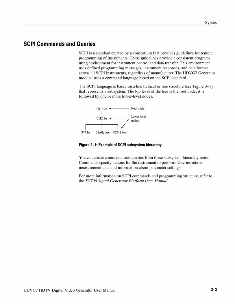
Syntax
HDVG7 HDTV Digital Video Generator User Manual 3- 3
SCPI Commands and QueriesSCPI is a standard created by a consortium that provides guidelines for remoteprogramming of instruments. These guidelines provide a consistent program-ming environment for instrument control and data transfer. This environmentuses defined programming messages, instrument responses, and data formatacross all SCPI instruments, regardless of manufacturer. The HDVG7 Generatormodule uses a command language based on the SCPI standard.
The SCPI language is based on a hierarchical or tree structure (see Figure 3--1)that represents a subsystem. The top level of the tree is the root node; it isfollowed by one or more lower-level nodes.
DIAMeter
OUTPut
CIRCle
POSitionSTATe
Root node
Lower-levelnodes
Figure 3- 1: Example of SCPI subsystem hierarchy
You can create commands and queries from these subsystem hierarchy trees.Commands specify actions for the instrument to perform. Queries returnmeasurement data and information about parameter settings.
For more information on SCPI commands and programming structure, refer tothe TG700 Signal Generator Platform User Manual.

Syntax
3- 4 HDVG7 HDTV Digital Video Generator User Manual

HDVG7 HDTV Digital Video Generator User Manual 3- 5
Remote Commands
This section describes the remote commands used to control the HDVG7Generator module remotely. The commands to the module are divided into thefollowing three groups:
H MASS MEMORY commands (Refer to the TG700 TV Signal GeneratorPlatform User Manual)
H OUTPUT commands
H SENSE commands
MASS MEMORY CommandsTwo MASS MEMORY commands are listed here for your reference. You canuse these to load and query the output test signal. Detailed information for usingthese commands are located in the TG700 TV Signal Generator Platform UserManual.
:MMEMory:LOAD:SIGNal <module_name>,<signal_name>:MMEMory:LOAD:SIGNal <slot_number>,<signal_name>
Loads a signal into the specified module.
:MMEMory:SIGNal:ACTive? <slot_number>|<module_name>
Returns the current output signal of the specified module.

Remote Commands
3- 6 HDVG7 HDTV Digital Video Generator User Manual
OUTPUT CommandsUse these commands control the output parameters of the module. These includeembedded audio and circle/text/logo overlay.
:OUTPut<n>:CIRCle:STATe ON|OFF:DIAMeter <numeric_value>:POSition:HORizontal <numeric_value>:VERTical <numeric_value>
:EAUDio:CHANnel<n>:AMPLitude <numeric_value>:FREQuency <numeric_value>:CLICk OFF|1|2|3|4
:GROup<n>:STATe ON|OFF:PREemphasis OFF|CD|CCITt:NBITs 20|24:SAMPLIng FRAMe|NOFRame|ASYNc
:LOGO:STATe ON|OFF:POSition:HORizontal <numeric_value>:VERTical <numeric_value>
:SELect <logo_name>:SAVe
:MOVe:HORizontal <numeric_value>:VERTical <numeric_value>:PERiod <numeric_value>:RANDom[:STATe] ON|OFF
:OVERlay:BLINk:STATe ON|OFF:PERiod <numeric_value>
:TEXT:STATe ON|OFF:DATA <string>:POSition:HORizontal <numeric_value>:VERTical <numeric_value>
:SAVe
Command Tree

Remote Commands
HDVG7 HDTV Digital Video Generator User Manual 3- 7
:VIDeo:Y:STATe ON|OFF
:PB:STATe ON|OFF
:PR:STATe ON|OFF
:AVTiming:STATe ON|OFF
:STANdard HD1080_60I|HD1080_59I|HD1080_50I|HD1080_24SF|HD1080_23SF|HD1080_30P|HD1080_29P|HD1080_25P|HD1080_24P|HD1080_23P|HD1035_60I|HD1035_59I|HD720_60P|HD720_59P|HD720_50P|HD720_30P|HD720_29P|HD720_25P|HD720_24P|HD720_23P
:SIGNal BLACk|GRAY|FF50P|WHITe
:OUTPut1:CIRCle:STATe ON|OFF
Turns the circle overlay on the video signal on or off. You can use 1or 0 instead of ON or OFF.
:OUTPut1:CIRCle:STATe?
Returns the current circle overlay state.
:OUTPut1:CIRCle:DIAMeter <numeric_value>
Sets the diameter of the displayed circle. The unit is percent of activepicture height. You can set the diameter from 0 % to 100 % in 1 %steps. You can also use MIN, MAX, or DEF instead of a numericvalue.
:OUTPut1:CIRCle:DIAMeter?
Returns the diameter of the displayed circle.
:OUTPut1:CIRCle:POSition:HORizontal <numeric_value>
Sets the horizontal position of the circle as it appears on the activesignal. The unit is percent of active picture width. You can set theposition from --50 % to +50 % in 1 % steps. You can also use MIN,MAX, or DEF instead of a numeric value.
Command Description

Remote Commands
3- 8 HDVG7 HDTV Digital Video Generator User Manual
:OUTPut1:CIRCle:POSition:HORizontal?
Returns the current horizontal position of the circle as it appears onthe active signal.
:OUTPut1:CIRCle:POSition:VERTical <numeric_value>
Sets the vertical position of the circle as it appears on the activesignal. The unit is percent of active picture height. You can set theposition from --50 % to +50 % in 1 % steps. You can also use MIN,MAX, or DEF instead of a numeric value.
:OUTPut1:CIRCle:POSition:VERTical?
Returns the current vertical position of the circle as it appears on theactive signal.
:OUTPut<n>:EAUDio:CHANnel<m>:AMPLitude <numeric_value>
Sets the amplitude of a specific embedded audio channel for theselected outputs. You can set the amplitude from --60 dBFS to0 dBFS in 1 dBFS steps. The <n> in the command represents theoutput connector type. “1” represents the SIGNAL connectors and“2” represents the optional BLACK connectors. The <m> in thecommand represents the channel number and you can use anychannel number from 1 through 16.
:OUTPut<n>:EAUDio:CHANnel<m>:AMPLitude?
Returns the current amplitude of a specific embedded audio channelfor the selected outputs. The <n> in the command represents theoutput connector type. “1” represents the SIGNAL connectors and“2” represents the optional BLACK connectors. The <m> in thecommand represents the channel number and you can use anychannel number from 1 through 16.
:OUTPut<n>:EAUDio:CHANnel<m>:FREQuency <numeric_value>
Sets the frequency of a specific embedded audio channel for theselected outputs. The frequency choices are --1, 0, 50, 100, 150, 200,250, 300, 400, 500, 600, 750, 800, 1000, 1200, 1500, 1600, 2000,2400, 3000, 3200, 4000, 4800, 5000, 6000, 8000, 9600, 10000,12000, 15000, 16000, or 20000. For --1, the output of the audio datais disabled. The <n> in the command represents the output connectortype. “1” represents the SIGNAL connectors and “2” represents theoptional BLACK connectors. The <m> in the command representsthe channel number and you can use any channel number from 1through 16.

Remote Commands
HDVG7 HDTV Digital Video Generator User Manual 3- 9
:OUTPut<n>:EAUDio:CHANnel<m>:FREQuency?
Returns the current frequency of a specific embedded audio channelfor the selected outputs. The <n> in the command represents theoutput connector type. “1” represents the SIGNAL connectors and“2” represents the optional BLACK connectors. The <m> in thecommand represents the channel number and you can use anychannel number from 1 through 16.
:OUTPut<n>:EAUDio:CHANnel<m>:CLICk 0|1|2|3|4
Sets the audio click of a specific audio channel for the selectedoutputs. You can select 0, 1 (second), 2 (seconds), 3 (seconds) or 4(seconds). When 1, 2, 3 or 4 is selected, the audio click becomesvalid. Audio Tone is turned off for 0.25 seconds around the time ofthe click. The <n> in the command represents the output connectortype. “1” represents the SIGNAL connectors and “2” represents theoptional BLACK connectors. The <m> in the command representsthe channel number and you can use any channel number from 1through 16.
:OUTPut<n>:EAUDio:CHANnel<m>:CLICk?
Returns the current audio click settings of a specific audio channelfor the selected outputs. The <n> in the command represents theoutput connector type. “1” represents the SIGNAL connectors and“2” represents the optional BLACK connectors. The <m> in thecommand represents the channel number and you can use anychannel number from 1 through 16.
:OUTPut<n>:EAUDio:GROup<m>:STATe ON|OFF
Turns the output of a specific audio group for the selected outputs onor off. You can also use 1 or 0 instead of ON or OFF. The <n> in thecommand represents the output connector type. “1” represents theSIGNAL connectors and “2” represents the optional BLACKconnectors. The <m> in the command represents the group numberand you can use any channel number from 1 through 4.
:OUTPut<n>:EAUDio:GROup<m>:STATe?
Returns the current output state of a specific audio group for theselected outputs. The <n> in the command represents the outputconnector type. “1” represents the SIGNAL connectors and “2”represents the optional BLACK connectors. The <m> in thecommand represents the group number and you can use any channelnumber from 1 through 4.

Remote Commands
3- 10 HDVG7 HDTV Digital Video Generator User Manual
:OUTPut<n>:EAUDio:GROup<m>:PREemphasis OFF|CD|CCITt
Turns the preemphasis bits on or off in the audio signal of a specificembedded audio group for the selected outputs. The signal itselfdoes not have preemphasis, but you can set the bits in order to checkother equipment. The <n> in the command represents the outputconnector type. “1” represents the SIGNAL connectors and “2”represents the optional BLACK connectors. The <m> in thecommand represents the group number and you can use any channelnumber from 1 through 4.
:OUTPut<n>:EAUDio:GROup<m>:PREemphasis?
Returns the current preemphasis bits settings of a specific embeddedaudio group for the selected outputs. The <n> in the commandrepresents the output connector type. “1” represents the SIGNALconnectors and “2” represents the optional BLACK connectors. The<m> in the command represents the group number and you can useany channel number from 1 through 4.
:OUTPut<n>:EAUDio:GROup<m>:NBITs 20|24
Sets the sample bits of a specific embedded audio group for theselected outputs. The <n> in the command represents the outputconnector type. “1” represents the SIGNAL connectors and “2”represents the optional BLACK connectors. The <m> in thecommand represents the group number and you can use any channelnumber from 1 through 4.
:OUTPut<n>:EAUDio:GROup<m>:NBITs?
Returns the current sample bits of a specific embedded audio groupfor the selected outputs. The <n> in the command represents theoutput connector type. “1” represents the SIGNAL connectors and“2” represents the optional BLACK connectors. The <m> in thecommand represents the group number and you can use any channelnumber from 1 through 4.
:OUTPut<n>:EAUDio:GROup<m>:SAMPLIng FRAMe|NOFRame|ASYNc
Sets the sampling alignment status bits in the audio signal of aspecific embedded audio group for the selected outputs. The <n> inthe command represents the output connector type. “1” representsthe SIGNAL connectors and “2” represents the optional BLACKconnectors. The <m> in the command represents the group numberand you can use any channel number from 1 through 4.

Remote Commands
HDVG7 HDTV Digital Video Generator User Manual 3- 11
:OUTPut<n>:EAUDio:GROup<m>:SAMPLIng?
Returns the current sampling alignment status bits settings of aspecific embedded audio group for the selected outputs. The <n> inthe command represents the output connector type. “1” representsthe SIGNAL connectors and “2” represents the optional BLACKconnectors. The <m> in the command represents the group numberand you can use any channel number from 1 through 4.
:OUTPut1:LOGO:STATe ON|OFF
Turns the logo overlay display on the video signal on or off. You canalso use 1 or 0 instead of ON or OFF.
:OUTPut1:LOGO:STATe?
Returns the current logo overlay state.
:OUTPut1:LOGO:POSition:HORizontal <numeric_value>
Sets the horizontal position of the logo as it appears on the activesignal. The unit is percent of active picture width. You can set theposition from --100 % to 0 % in 0.1 % steps. You can also use MIN,MAX, or DEF instead of a numeric value.
:OUTPut1:LOGO:POSition:HORizontal?
Returns the current horizontal position of the logo.
:OUTPut1:LOGO:POSition:VERTical <numeric_value>
Sets the vertical position of the logo as it appears on the activesignal. The unit is percent of active picture height. You can set theposition from --100 % to 0 % in 0.1 % steps. You can also use MIN,MAX, or DEF instead of a numeric value.
:OUTPut1:LOGO:POSition:VERTical?
Returns the current vertical position of the logo.
:OUTPut1:LOGO:SELect <logo_name>
Selects the logo used for the logo overlay.
:OUTPut1:LOGO:SELect?
Returns the current logo used for the logo overlay.
:OUTPut1:LOGO:SAVe
Saves the current display position of the logo to the logo file. Thereare no arguments.

Remote Commands
3- 12 HDVG7 HDTV Digital Video Generator User Manual
:OUTPut1:MOVe:HORizontal <numeric_value>
Sets the amount of horizontal scrolling in the moving picture mode.You can set the value from --252 to +252 in 4 samples steps.
:OUTPut1:MOVe:HORizontal?
Returns the amount of horizontal scrolling in the moving picturemode.
:OUTPut1:MOVe:VERTical <numeric_value>
Sets the amount of vertical scrolling in the moving picture mode.You can set the value from --252 to +252 in 1 line steps.
:OUTPut1:MOVe:VERTical?
Returns the amount of vertical scrolling in the moving picture mode.
:OUTPut1:MOVe:PERiod <numeric_value>
Sets the time interval between occurrences of the scrolling. You canset the value from 1 to 16 in 1 field steps.
:OUTPut1:MOVe:PERiod?
Returns the time interval between occurrences of the scrolling.
:OUTPut1:MOVe:RANDom[:STATe] ON|OFF
Turns the random scrolling mode on or off. You can also use 1 or 0instead of ON or OFF.
:OUTPut1:MOVe:RANDom[:STATe]?
Returns the current state of the random scrolling mode.
:OUTPut1:OVERlay:BLINk:STATe ON|OFF
Turns on or off the blinking mode for the logo, text, and circleoverlay. You can also use 1 or 0 instead of ON or OFF
:OUTPut1:OVERlay:BLINk:STATe?
Returns the current state of the blinking mode for the logo, text, andcircle overlay.
:OUTPut1:OVERlay:BLINk:PERiod <numeric_value>
Sets the blinking interval of the blinking mode for the logo, text, andcircle overlay. You can set the value as 0.5 seconds or 1.0 seconds.

Remote Commands
HDVG7 HDTV Digital Video Generator User Manual 3- 13
:OUTPut1:OVERlay:BLINk:PERiod?
Returns the blinking interval of the blinking mode for the logo, text,and circle overlay.
:OUTPut1:TEXT:STATe ON|OFF
Turns the text overlay display on the video signal on or off. You canalso use 1 or 0 instead of ON or OFF.
:OUTPut1:TEXT:STATe?
Returns the current text overlay state.
:OUTPut1:TEXT:DATA <string>
Sets the current string for the text mode.
:OUTPut1:TEXT:DATA?
Returns the current string for the text mode.
:OUTPut1:TEXT:POSition:HORizontal <numeric_value>
Sets the text horizontal position in the video signal. The unit ispercent of active picture width. You can set the position from 0 % to100 % in 1 % steps. You can also use MIN, MAX, or DEF instead ofthe numeric value.
:OUTPut1:TEXT:POSition:HORizontal?
Returns the current text horizontal position in the video signal.
:OUTPut1:TEXT:POSition:VERTical <numeric_value>
Sets the text vertical position in the video signal. The unit is percentof active picture height. You can set the position from 0 % to 100 %in 1 % steps. You can also use MIN, MAX, or DEF instead of anumeric value.
:OUTPut1:TEXT:POSition:VERTical?
Returns the current text vertical position in the video signal.
:OUTPut1:TEXT:SAVe
Saves the current text and its display position to the signal file.There are no arguments.
:OUTPut1:VIDeo:Y:STATe ON|OFF
Turns the Y component of the serial digital video signals on or off.You can also use 1 or 0 instead of ON or OFF.

Remote Commands
3- 14 HDVG7 HDTV Digital Video Generator User Manual
:OUTPut1:VIDeo:Y:STATe?
Returns the current Y component output state of the serial digitalvideo signals.
:OUTPut1:VIDeo:PB:STATe ON|OFF
Turns the PB component of the serial digital video signals on or off.You can also use 1 or 0 instead of ON or OFF.
:OUTPut1:VIDeo:PB:STATe?
Returns the current PB component output state of the serial digitalvideo signals.
:OUTPut1:VIDeo:PR:STATe ON|OFF
Turns the PR component of the serial digital video signals on or off.You can also use 1 or 0 instead of ON or OFF.
:OUTPut1:VIDeo:PR:STATe?
Returns the current output state of the PR component of the serialdigital video signals.
:OUTPut1:VIDeo:AVTiming:STATe ON|OFF
Turns the output mode for an audio/video timing measurement on oroff. Refer to Operating Basics for detailed information about themode. You can also use 1 or 0 instead of ON or OFF.
:OUTPut1:VIDeo:AVTiming:STATe?
Returns the current output mode setting for an audio/video timingmeasurement.
:OUTPut2:STANdard HD1080_60I|HD1080_59I|HD1080_50I|HD1080_24SF|HD1080_23SF|HD1080_30P|HD1080_29P|HD1080_25P|HD1080_24P|HD1080_23P|HD1035_60I|HD1035_59I|HD720_60P|HD720_59P|HD720P_50P|HD720_30P|HD720_29P|HD720_25P|HD720_24P|HD720_23P
Sets the video standard for the serial digital black signals outputfrom the BLACK connectors. The choices are HD 1080_60I toHD720_23P. This command is only available if Option BK isinstalled.

Remote Commands
HDVG7 HDTV Digital Video Generator User Manual 3- 15
:OUTPut<n>:STANdard?
Returns the video standard for the selected output. The <n> in thecommand represents the output connector type. “1” represents theSIGNAL connectors and “2” represents the optional BLACKconnectors.
:OUTPut2:SIGNal BLACk|GRAY|FF50P|WHITe
Sets the type of the serial digital black signals output from theBLACK connectors. The options are BLACK (serial digital blacksignal), GRAY (40% flat field signal), FF50P (50% flat field signal),or WHITe (100% flat field signal). This command is only availableif Option BK is installed.
:OUTPut2:SIGNal?
Returns the current serial digital black signals output from theBLACK connectors. This command is only available if Option BKis installed.
:OUTPut:CONFigure?
Returns the availability of serial digital black signal output option(Option BK). “1” indicates that the option is available and “0”indicates that the option is not available.
SENSE CommandsUse these commands to set the timing offset of the SIGNAL outputs and theBLACK outputs (Option BK only) relative to the internal reference signal (framereset signal).
Refer to Operating Basics for detailed information about the setting range.
:SENSe<n>:CORRection:MDELay:HORizontal <numeric_value>:STEP <numeric_value>
:VERTical <numeric_value>:STEP <numeric_value>
Command Tree

Remote Commands
3- 16 HDVG7 HDTV Digital Video Generator User Manual
:SENSe<n>:CORRection:MDELay:HORizontal <numeric_value>
Sets the horizontal timing offset of the selected outputs. The timingresolution is clock-cycles. The units are microseconds. You can useUP, DOWN, or DEF instead of the numeric value. If the argumentexceeds the horizontal time value, then the vertical offset is adjustedto accommodate the requested delay. The <n> in the commandrepresents the type of output connector. “1” represents the SIGNALconnectors and “2” represents the BLACK connectors.
:SENSe<n>:CORRection:MDELay:HORizontal?
Returns the current horizontal timing offset of the selected outputs.The <n> in the command represents the type of output connector.“1” represents the SIGNAL connectors and “2” represents theBLACK connectors.
:SENSe<n>:CORRection:MDELay:HORizontal:STEP <numeric_value>
Sets the step increment used by the UP or DOWN commands. Theunits are microseconds. You can use MIN, MAX, or DEF instead ofa numeric value. The <n> in the command represents the type ofoutput connector. “1” represents the SIGNAL connectors and “2”represents the BLACK connectors.
:SENSe<n>:CORRection:MDELay:HORizontal:STEP?
Returns the current step increment. The <n> in the commandrepresents the type of output connector. “1” represents the SIGNALconnectors and “2” represents the BLACK connectors.
:SENSe<n>:CORRection:MDELay:VERTical <numeric_value>
Sets the vertical timing offset of the selected outputs. The argumentcan be a floating point value that is translated into integer lines witha horizontal offset. You can use UP, DOWN, or DEF instead of anumeric value. The <n> in the command represents the type ofoutput connector. “1” represents the SIGNAL connectors and “2”represents the BLACK connectors.
:SENSe<n>:CORRection:MDELay:VERTical?
Returns the current vertical timing offset of the selected outputs. The<n> in the command represents the type of output connector. “1”represents the SIGNAL connectors and “2” represents the BLACKconnectors.
Command Description

Remote Commands
HDVG7 HDTV Digital Video Generator User Manual 3- 17
:SENSe<n>:CORRection:MDELay:VERTical:STEP <numeric_value>
Sets the step increment used by the UP or DOWN commands. Youcan use MIN, MAX, or DEF instead of a numeric value. The <n> inthe command represents the type of output connector. “1” representsthe SIGNAL connectors and “2” represents the BLACK connectors.
:SENSe<n>:CORRection:MDELay:VERTical:STEP?
Returns the current step increment. The <n> in the commandrepresents the type of output connector. “1” represents the SIGNALconnectors and “2” represents the BLACK connectors.

Remote Commands
3- 18 HDVG7 HDTV Digital Video Generator User Manual

Appendices


HDVG7 HDTV Digital Video Generator User Manual A- 1
Appendix A: Specifications
Tables A--1 through A--4 list the electrical and environmental characteristics ofthe HDVG7 Generator module.
Electrical Characteristics
Table A- 1: Serial digital video signal outputs
Characteristic Performance requirements Reference information
Connector BNC
Number of outputs 2 SIGNAL 1 and SIGNAL 2
Bit Rate 1.485 Gbps
1.485/1.001 Gbps
Signal amplitude, typical 800 mV
Rise and fall times, typical ≤270 ps 20% to 80%
Jitter, typical ≤135 ps Alignment jitter
Return loss ≥15 dB 5 MHz to 750 MHz
≥10 dB 750 MHz to 1.485 GHz
Table A- 2: Serial digital black signal outputs (Option BK only)
Characteristic Performance requirements Reference information
Connector BNC
Number of outputs 2 BLACK 1 and BLACK 2
Bit Rate 1.485 Gbps
1.485/1.001 Gbps
Signal amplitude, typical 800 mV
Rise and fall times, typical ≤270 ps 20% to 80%
Jitter, typical ≤135 ps Alignment jitter
Return loss ≥15 dB 5 MHz to 750 MHz
≥10 dB 750 MHz to 1.485 GHz

Appendix A: Specifications
A- 2 HDVG7 HDTV Digital Video Generator User Manual
Table A- 3: Embedded audio
Characteristic Performance requirements Reference information
Number of channels 16 channels in 4 groups; 8 AES/EBU audiopairs
Audio tones
Frequency Silence to 20 kHz; 31 discrete settings
Level --60 to 0 dBFS in 1 dB steps
Pre-emphasis Emphasis status bits can be inserted.
Environmental Characteristics
Table A- 4: Environmental characteristics
Characteristic Description
Temperature
Operating 0 _C to +50 _C
Non-operating --20 _C to +60 _C
Relative Humidity
Operating 20% to 80% (No condensation); Maximum wet-bulb temperature 29.4 _C
Non-operating 5% to 90% (No condensation); Maximum wet-bulb temperature 40.0 _C
Altitude
Operating To 4.5 km (15,000 feet)Maximum operating temperature decreases 1 _C each 300 m above 1.5 km.
Non-operating To 15 km (50,000 feet)
Vibration
Operating 3.04 m/s2 (0.31 Grms), 5 Hz to 500 Hz, 10 min, three axes
Non-operating 23.3 m/s2 (2.38 Grms), 5 Hz to 500 Hz, 10 min, three axes
Shock
Non-operating 294 m/s2 (30 G), half-sine, 11 ms duration

Index


HDVG7 HDTV Digital Video Generator User Manual Index- 1
IndexAAccessoriesoptional, 1--2standard, 1--2
AUDIO CHANNEL submenu, 2--13Audio click, 2--14AUDIO GROUP submenu, 2--12
BBLACK 1 connector, 2--19BLACK 2 connector, 2--19Black submenu (Option BK only), 2--17
CCircle overlay, 2--10CIRCLE submenu, 2--10CommandsRules for forming, 3--1Syntax, 3--1
EElectrical specifications, A--1Embedded audio, 1--1, 2--12Environmental specifications, A--2
FFactory default settings, 2--19Functional check, 1--3
HHDVG7 features, 1--1HDVG7 module main menu, 2--4Hierarchy (SCPI), 3--3
IID TEXT submenu, 2--9Installation, 1--3
LLogo overlay, 2--8LOGO submenu, 2--8
MManuals, Related, iiiMASS MEMORY commands, 3--5MOVING PICTURE submenu, 2--6
OOperating procedure, 2--1Option, 1--2Optional accessories, 1--2OUTPUT commands, 3--6OVERLAY submenu, 2--7
PProduct description, 1--1
RRear-panel connectors, 2--18Related Manuals, iiiRemote commands, 3--5Rules, Command forming, 3--1
SSCPI, Subsystem hierarchy tree, 3--3SCPI commands and queries syntax, 3--3–3--4SENSE commands, 3--15SIGNAL 1 connector, 2--19SIGNAL 2 connector, 2--19Signal set assigned to the test signal buttons, 2--3SpecificationsElectrical, A--1Environmental, A--2
Standard accessories, 1--2Syntax, Command, 3--1

Index
Index- 2 HDVG7 HDTV Digital Video Generator User Manual
TText overlay, 2--9TIMING submenu, 2--15
VVIDEO submenu, 2--16