tgis–sl tire geometry inspection system - micro-poise · 1. micro-poise measurement systems, is a...
TRANSCRIPT

TGIS–SL ® Tire Geometry Inspection System
MEASUREMENT SYSTEMS
1
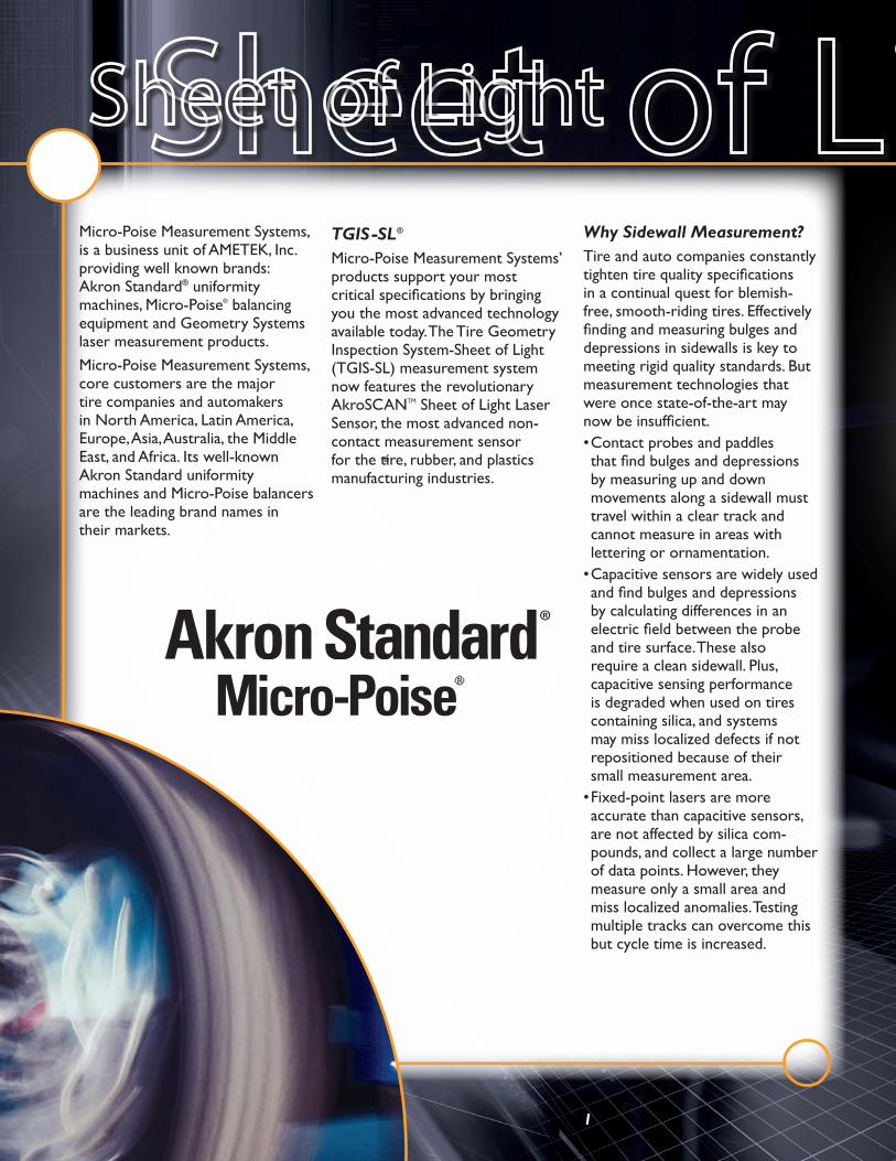
Micro-Poise Measurement Systems, is a business unit of AMETEK, Inc. providing well known brands: Akron Standard® uniformity machines, Micro-Poise® balancing equipment and Geometry Systems laser measurement products.Micro-Poise Measurement Systems, core customers are the major tire companies and automakers in North America, Latin America, Europe, Asia, Australia, the Middle East, and Africa. Its well-known Akron Standard uniformity machines and Micro-Poise balancers are the leading brand names in their markets.
TGIS-SL ®
Micro-Poise Measurement Systems’ products support your most critical specifications by bringing you the most advanced technology available today. The Tire Geometry Inspection System-Sheet of Light (TGIS-SL) measurement system now features the revolutionary AkroSCANTM Sheet of Light Laser Sensor, the most advanced non-contact measurement sensor for the tire, rubber, and plastics manufacturing industries.
Why Sidewall Measurement?Tire and auto companies constantly tighten tire quality specifications in a continual quest for blemish-free, smooth-riding tires. Effectively finding and measuring bulges and depressions in sidewalls is key to meeting rigid quality standards. But measurement technologies that were once state-of-the-art may now be insufficient.• Contact probes and paddles that find bulges and depressions by measuring up and down movements along a sidewall must travel within a clear track and cannot measure in areas with lettering or ornamentation.
• Capacitive sensors are widely used and find bulges and depressions by calculating differences in an electric field between the probe and tire surface. These also require a clean sidewall. Plus, capacitive sensing performance is degraded when used on tires containing silica, and systems may miss localized defects if not repositioned because of their small measurement area.
• Fixed-point lasers are more accurate than capacitive sensors, are not affected by silica com-pounds, and collect a large number of data points. However, they measure only a small area and miss localized anomalies. Testing multiple tracks can overcome this but cycle time is increased.
®
®
®

The Sheet of Light SolutionThe new AkroSCAN laser sensor from Micro-Poise Measurement Systems has the largest measure-ment area and field of view, fastest scanning rates, and highest resolu-tion of any similar sensor on the market today. All this, combined with the Ethernet Gigabit Commu-nications, offers unmatched value in the industry. In comparison to the original TGIS-SL system, the new AkroSCAN sensor triples the area scanned, allowing for a more complete measurement of the tire. Additionally, tire manufacturers can now test a wider range of product through the system, including truck
tires. The entire radial tread width, up to 320mm, can be scanned with multiple tread tracks graded for runout. Passenger and truck tires can be quickly scanned for bulges and dents along a 170mm area of the sidewall. With increased mea-surement capabilities, tire manu-facturers will have the ability to build a complete picture of the tire, from bead to bead, on most sizes. This will help improve the sidewall appearance of tires and improve testing for ride quality issues on the tread surface.Another improvement that can provide significant savings for the
tire manufacturer is the increase in the scanning rate for the AkroSCAN, from 2000 to 4000 Hz, which helps to reduce cycle times in the final finish process. Moreover, the new scan rate boasts an increase in resolution, with 3-6 million data points, depending on 2kHz or 4kHz settings. This can aid manufacturers in scanning tires that have excessive sidewall lettering and designs. With the increase in resolution also comes an improvement in commu-nications through the use of Ethernet, allowing increased data to be reliably transmitted over much longer distances.
Laser beam dramatized for illustrative purposes
2
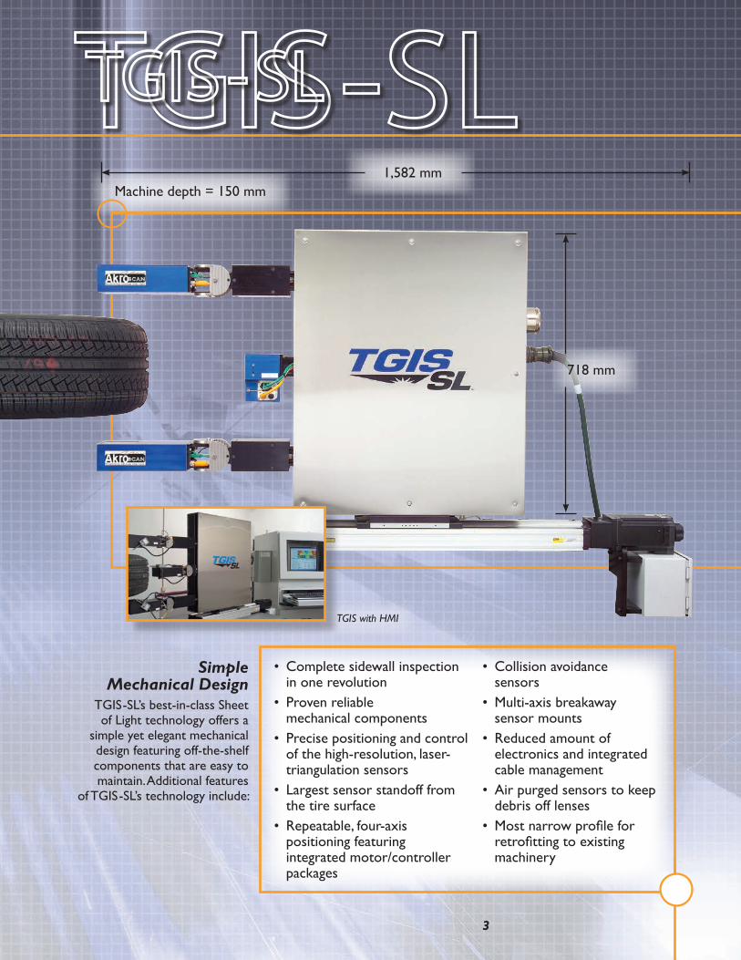
Simple Mechanical Design
TGIS-SL’s best-in-class Sheet of Light technology offers a
simple yet elegant mechanical design featuring off-the-shelf components that are easy to maintain. Additional features
of TGIS-SL’s technology include:
• Complete sidewall inspection in one revolution
• Proven reliable mechanical components
• Precise positioning and control of the high-resolution, laser-triangulation sensors
• Largest sensor standoff from the tire surface
• Repeatable, four-axis positioning featuring integrated motor/controller packages
• Collision avoidance sensors
• Multi-axis breakaway sensor mounts
• Reduced amount of electronics and integrated cable management
• Air purged sensors to keep debris off lenses
• Most narrow profile for retrofitting to existing machinery
718 mm
1,582 mmMachine depth = 150 mm
TGIS with HMI
3

Superior SoftwareTGIS-SL’s production-ready soft-
ware separates it from the compe-tition. With filtering programs that
eliminate irrelevant information, the software can analyze and display data accurately for any data set,
whether a single track or an entire sidewall. TGIS-SL software also
performs the following:
• Calculates bulge, de-pressions, and run-out geometry and displays measurements in a power-ful, color-mapped image and results table
• Calculates tire anomaly locations from a fixed point on the tire
Easy to service - components readily available
Breakaway laser heads
AkroSCAN Sensor
Bulge, depression, PK-PK Accuracy:
Repeatability:
0.05 mm 0.025 mm
Lateral, Radial, Wobble RO Accuracy:
Repeatability:
0.05 mm 0.025 mm
Data Collection 1 revolution
RPM 20 - 120 RPM
Profiles per Revolution 4,000
Points per Profile 1,536
Points per Scan 6,144,000
**Profile Width Lateral Sensors: Radial Sensors:
170 mm 300 mm
**Laser Measurement Range Lateral Sensors: Radial Sensors:
100 mm 120 mm
**Sensor Standoff Lateral Sensors: Radial Sensors:
50 - 150 mm 190 - 310 mm
Laser Classification IIIA (US) / IIIR (Europe)
Communication Protocol Ethernet Gigabit
Distance to Object Calibration Absolute
Encoder Interface Direct to Sensor
*Compared to measurements taken with a Coordinate Measuring Machine on a metal reference geometry.
**Other sensor configurations available upon request.
Specifications
• Offers off-line analyses• Associates data with
individual tire IDs• Simplifies entry of recipes
and machine logic • Uses “exception region”
technology to inspect through sidewall lettering and ornamentation
4

Hardware and Software DetailsThe TGISserver software is the measurement heart of the TGIS-SL
System, performing the data col-lection and reduction. TGISserver also reads the test recipe, controls motion on the Micro-Poise Geometry Systems transport, and communicates with a host application such as a Machine HMI or the Micro-Poise Geometry Systems RTviewer for displaying real-time results.TGIS –SL’s Windows® PC-based hardware and software are housed in a compact, stand-alone, rolling cabinet that also protects its mechanical, optical, and electronic components. The system connects to a standard TCP/IP-based network and any PC on the network can monitor it.
Easy to ProgramThe Micro-Poise Geometry Systems RADViewer is the visualization heart of the TGIS-SL system. This is the software application that allows a user to visually specify a test recipe and to view the measurement results in detail. The RADViewer can be launched directly from a Machine HMI or by double-clicking on a TGIS recipe file or result file.TGIS-SL’s RADViewer software offers a familiar Windows look and feel to users, accompanied by self-explanatory point-and-click options that make it easy to set up process logic and recipes. Users customize where data is collected and how information is presented. They also define tire measurement locations, what to report, bulge and depres-sion thresholds and machine-cycle interface logic.
5

6
Configurations The TGIS-SL laser transport assembly comes in a variety of sizes to accommodate mechanical inter-face to the host machine and allow measurements of passenger car as well as over the road truck and bus tire sizes. Customers can order TGIS-SL: • To upgrade an existing Akron Standard or other uniformity machine
• As an option on a new Akron Standard uniformity machine
• As a new Geometry Station that includes the Akron Standard inflation machine
• To upgrade an existing Geometry Station
• As a customized “sensor only” system with or without motion control
• Configured for new and/or up-grades to truck/bus tires machines
OptionsTGIS-SL machines can be set up with: • Measurement Verification Device – Includes a rotating metal disk with bulges and depressions measured to certified dimensions. It attaches to the TGIS transport frame and offers an integrated drive motor that turns the disk at 60 rpm.
• Mounting Bracket Kit – Special mounting bracket kits may be required to integrate the TGIS-SL to certain equipment.
• X-Axis Transport Slide Length Variants – Provide an x-axis base-plate slide for automatic radial-axis positioning. Extended slide lengths are available.
To obtain information, to arrange controlled sample testing of your products, or to schedule a demonstration and Micro-Poise plant tour, call Geometry Systems sales at Micro-Poise Measurement Systems, 330-541-9100 or email to [email protected] our Website at www.micropoise.comMicro-Poise Measurement Systems, LLC reserves the right to make changes in specifications shown herein, add improvements, or discontinue manufacture at any time without notice or obligation.

Akron Standard, Micro-Poise, TGIS, and Collmann - © 2014, by AMETEK, Inc. All rights reserved.
Micro-Poise Measurement SystemsUSA555 Mondial ParkwayStreetsboro, OH USA 44241-4510Telephone: +1-330-541-9100Fax: +1-330-541-9111Website: www.micropoise.com
Globally Positioned to Serve YouMicro-Poise Measurement Systems LLC serves the tire and automotive industry all over the world.
Micro-Poise Headquarters
ces, Stocking Locations and Services
Sales Representatives
Micro-Poise Measurement Systems India306, Delta wing, 3rd Floor Raheja Towers,177, Anna Salai,Chennai-600002, IndiaTelephone: +91 44 4959-1000 Fax: +91 44 4959-1021
Micro-Poise Industrial Equipment Co.BeijingRising International Industrial Park#1 Building, No. 29 Jinghai 3rd Road BDABeijing 100023, ChinaTelephone: +86-10-67892171/72/73Fax: +86-10-67892239
Micro-Poise Measurement SystemsGuangzhouRm. 1410-1412, Yian Plaza33 Jian She Liu Ma RoadGuangzhou 510060, ChinaTelephone: +86-20-8384-0122Fax: +86-20-8384-0123
MicroPoise Measurement SystemsEurope GmbHMoislinger Allee 22423558 LübeckGermanyTelephone: +49 451 89096 0Fax: +49 451 89096 24
Micro-Poise Measurement SystemsKorea309, 3rd Floor, Gyeonggi R&DB Center906-5, lui-dong, Yeongtong-gu,Suwon-city, Gyeonggi-do, 443-270, KoreaTelephone: +82-31-888-5259Fax: +82-31-888-5228
MEASUREMENT SYSTEMS
5/14 MP-R5