tgt-calc-401-001 02/07/2013 project: hall d cryogenic
TRANSCRIPT

02/07/2013TGT-CALC-401-001
Project: Hall D Cryogenic Target
Tittle: General calculations for relief and storage pressures
Document Number: TGT-CALC-401-001
Revision: Original
Author: Dave Meekins Date: 2/6/2012
Checked: Date:
Approved: Date:
Code(s) of Record: ASME B31.3 2010ASME B31.12 2011ASME BPVC VIII D1 2010
Reference CodesAPI 520API 521NFPA 2,55,497CGA 5
Reference DrawingsTGT-401-0001-1000
Description:Hall D target relief calculations and volume estimate. The Schneider MEMO for loss of vacuum in a cryomodule is used as a design basis to determine the heat load from IV loss in the H2 target. Assume gas as it leaves the target is at 300K. This is overly consrvative. The target cell is made of kapton. Other system components are stainless steel. The cell will have the lowest design pressure; it will drive the design. The Weymouth friction factor will be used as it is conservative for all pipe sizes less than 20 inch NPS. Crane 410 is used as guidance.
Page 1 of 24

02/07/2013TGT-CALC-401-001
Design assumptions limits and set points for pressures
≔Pset ⋅30 Relief set pressure absolute
≔Patm ⋅14.7 atm pressure absolute
≔Pcold ⋅18 assumed cold operating pressure absolute
≔Pmax ⋅35 absolute design pressure of target cell
≔Pplate ⋅16.7 absolute parallel plate set pressure. Parallel plate is at exit of H2 vent
≔Pover =⋅Pmax 1.16 40.6 max allowed overpressure by code for redundant relief paths
Fluid Properties for H2, D2 and He:
Properties were determined for He at 5.2K and 35 psia where a test was performed on the JLAB Cryo modules. Properties of H2 were determined at 30 psia and 23 K which are the expected relief pressure and temperature respectively for the Hall D target
Moler masses of H2, D2 and He
≔MH2 ⋅2 ―― ≔MD2 ⋅4 ―― ≔MHe ⋅4 ――
Latent heat of H2, D2, and He
≔λH2 ⋅461 ―― ≔λD2 304 ―― ≔λHe 21 ――
gas constants
≔RH2 ⋅4124.3 ――⋅
≔RD2 ⋅2064 ――⋅
≔RHe ⋅2077.3 ――⋅
density of H2, D2 and He at 300K and 30 psia (P_set)
≔ρH2300 ⋅0.167 ――3
≔ρD2300 ⋅0.334 ――3
≔ρHe300 ⋅0.3316 ――3
Page 2 of 24

02/07/2013TGT-CALC-401-001
density of H2, D2, and He at 289K (60 F) and 14.7 psia
≔ρH2std ⋅0.0850 ――3
≔ρD2std ⋅0.1698 ――3
≔ρHestd ⋅0.1687 ――3
density of liquid H2 and D2 at the target operating temperatures and pressure
≔ρH2op ⋅72.26 ――3
≔ρD2op ⋅167.4 ――3
densities of H2 and from ideal gas law
≔ρH2(( ,T P)) ―――
P
⎛⎝ ⋅RH2 T⎞⎠
This group of constants are needed to scale the He loss of vacuum data from Schneider to the case of H2
≔KH2 ⋅0.0187 ――⋅
Thermal conductivity of H2 at film boiling condition
≔KHe ⋅0.0257 ――⋅
Thermal conductivity of He (at film boiling condition)
≔KD2 ⋅0.0137 ――⋅
est thermal cond of D2 at film boiling condition
≔THe ⋅5.2 Film boiling test temp for He from Schnieider MEMO
≔TH2 ⋅23 Film boiling temp for H2 at target vent condition
≔Troom ⋅300 room temperature
Specific heats of H2
≔cpH2 ⋅⋅0.143 105 ――⋅
≔cvH2 ⋅⋅0.102 105 ――⋅
Specific heats of D2
≔cvD2 ⋅5186 ――⋅
≔cpD2 ⋅7251 ――⋅
Page 3 of 24

02/07/2013TGT-CALC-401-001
Specific heats of He
≔cvHe ⋅3116 ――⋅
≔cpHe ⋅5193 ――⋅
Ratios of specific heats for H2, D2 and He
≔kH2 =――cpH2
cvH2
1.402 ≔kD2 =――cpD2
cvD2
1.398 ≔kHe =――cpHe
cvHe
1.667
viscosities of each gas at exit. The viscosity in the vent stack will vary from this by less than 1%
≔μH2300 ⋅⋅⋅0.8959 10−5 visc of H2 at 300K and 30 psi
≔μHe300 ⋅⋅⋅0.1993 10−4 visc of He at 300K and 30 psi
≔μD2300 ⋅1.39 μH2300 visc of D2 at 300K and 30 psi.
speed of sound in each gas
≔vsoundH2 ⋅1321 ― speed of sound for H2 at 300K and 30 psi
≔vsoundHe ⋅1020 ― speed of sound in He at 300K and 30 psi
estimated speed of sound in D2 at 300K and 30 psi from ideal gas model
≔vsoundD2 =‾‾‾‾‾‾‾‾‾
⋅kD2 ――Pset
ρD2300
930.528 ―
Critical flow pressure ratios for H2, D2, and He. determined using the ideal gas assumptions similar to API 520 eq 3.1
≔RcH2
⎛⎜⎝―――
2
+kH2 1
⎞⎟⎠
――kH2
−kH2 1
≔RcD2
⎛⎜⎝―――
2
+kD2 1
⎞⎟⎠
――kD2
−kD2 1
≔RcHe
⎛⎜⎝―――
2
+kHe 1
⎞⎟⎠
――kHe
−kHe 1
Page 4 of 24

02/07/2013TGT-CALC-401-001
Surface area and volume of liquid vessels
Surface area/volume of the cell:end cap D00000-03-00-2000
≔Dcap ⋅0.628 diameter of endo cap
≔Lcap ⋅0.188 end cap length
≔Acap +⋅⋅ Dcap Lcap ⋅2 ――Dcap
2
4
≔Vcap +⋅2 ―3
⎛⎜⎝――Dcap
2
⎞⎟⎠
3
⋅⋅―4
Dcap2 Lcap
cell main body D00000-03-00-2002 is frustum of a cone
≔D1 ⋅1.046
≔D2 ⋅0.61
≔Lmain ⋅14.04
≔Amain ⋅⋅―2
⎛⎝ +D1 D2⎞⎠
‾‾‾‾‾‾‾‾‾‾‾‾‾‾‾‾
+――――⎛⎝ −D1 D2
⎞⎠2
2Lmain
2 main cell body surface area
≔Vmain ⋅⋅―3
Lmain ―――――――⎛⎝ ++D1
2 ⋅D1 D2 D22 ⎞⎠
4main cell body volume
cell entrance tube D00000-03-00-2001
≔D1 ⋅0.91 ≔D2 ⋅0.738 ≔Lent ⋅3.79
surface area of entrance tube≔Aent ⋅⋅―
2⎛⎝ +D1 D2
⎞⎠
‾‾‾‾‾‾‾‾‾‾‾‾‾‾
+――――⎛⎝ −D1 D2
⎞⎠2
2Lent
2
Page 5 of 24

02/07/2013TGT-CALC-401-001
displaced volume of entrance tube ≔Vent ⋅⋅―
3⎛⎝ −Lent ⋅1.585 ⎞⎠ ―――――――
⎛⎝ ++D12 ⋅D1 D2 D2
2 ⎞⎠4
Fill and return leg tubes on cell D00000-03-00-2005. There are (3) tubes
≔Dfill ⋅0.375 Tube OD
≔Lfill ⋅4.25 est length of tubes to fitting
≔Afill ⋅⋅ Dfill Lfill area of one fill tube
≔Vfill ⋅⋅―4
Dfill2 Lfill volume of one fill tube
tubing from condenser to cell (loop tubing) (2) tubes, supply and return to cell
≔Lloop ⋅8 estimated length of each tube
≔Drl ⋅0.5 OD of return
≔Dsup ⋅0.25 OD of supply
≔Asup ⋅⋅ Dsup Lloop area of supply line
≔Arl ⋅⋅ Drl Lloop area of return line
≔Aloop +Arl Asup area of loop tubing
≔Vloop ⋅⋅―4
⎛⎝ +Drl2 Dsup
2 ⎞⎠ Lloop volume of loop tubing
Condenser
≔Lcond ⋅4 length of condenser
≔Dcond ⋅4 OD of condenser
≔Acond +⋅⋅ Dcond Lcond ⋅⋅2 ―4
Dcond2 surface area of condenser
≔Vcond ⋅⋅―1
2
⎛⎜⎝―4
⎞⎟⎠
Dcond2 Lcond conservative estimate of H2
volume in condenser is 1/2 total volume
Page 6 of 24

02/07/2013TGT-CALC-401-001
Total surface areas
≔Ains =++Acond Aloop ⋅3 Afill 0.204 2 total insulated area
≔Auns =++Amain ⋅2 Acap Aent 0.031 2 total uninsulated area
Total volume of liquid H2
≔VLH2 =−++++Vcond Vcap Vloop ⋅3 Vfill Vmain Vent 0.93
Supply and return lines which feed the target from the outside of the OVC are assumed to contain only gas as they extend to the OVC feedthru. These lines are assumed to be 3 ft long and have one 90 deg elbow inside the OVC and one outside. As they contain gas only, they are not considered in the relief load calculation below as containing liquid.
Page 7 of 24
02/07/2013TGT-CALC-401-001
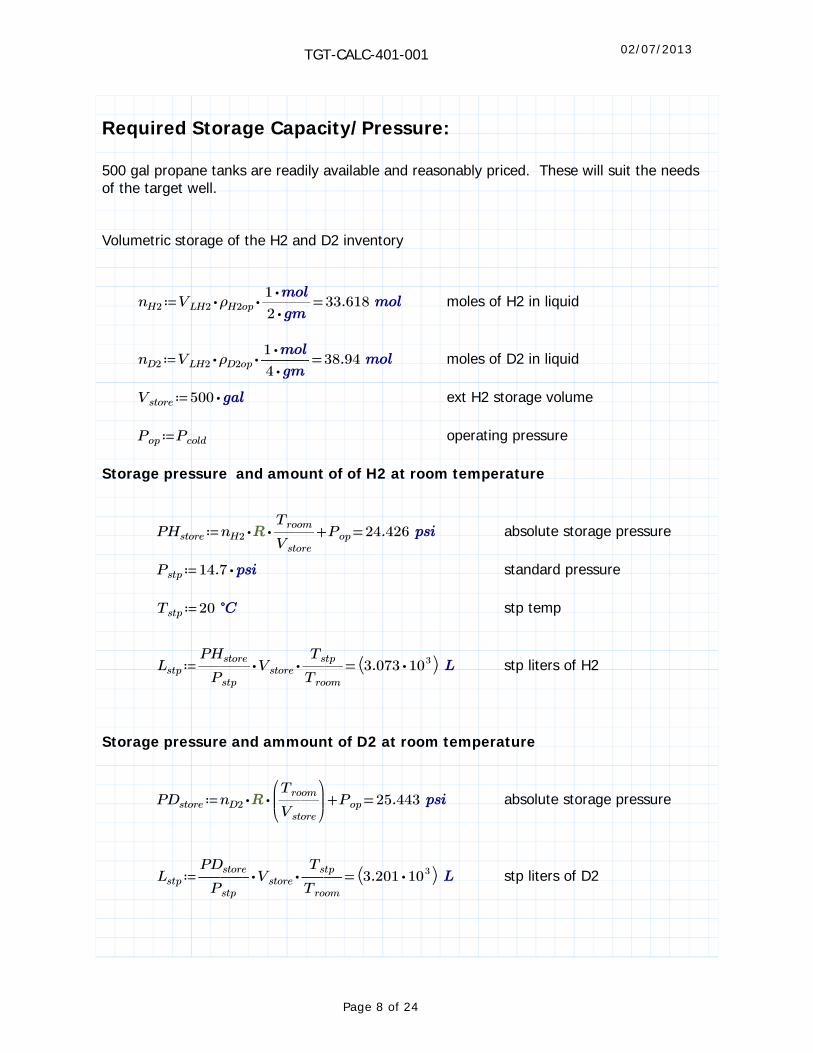
Required Storage Capacity/Pressure:
500 gal propane tanks are readily available and reasonably priced. These will suit the needs of the target well.
Volumetric storage of the H2 and D2 inventory
≔nH2 =⋅⋅VLH2 ρH2op ―――⋅1
⋅233.618 moles of H2 in liquid
≔nD2 =⋅⋅VLH2 ρD2op ―――⋅1
⋅438.94 moles of D2 in liquid
≔Vstore ⋅500 ext H2 storage volume
≔Pop Pcold operating pressure
Storage pressure and amount of of H2 at room temperature
≔PHstore =+⋅⋅nH2 ――Troom
Vstore
Pop 24.426 absolute storage pressure
≔Pstp ⋅14.7 standard pressure
≔Tstp 20 stp temp
≔Lstp =⋅⋅―――PHstore
Pstp
Vstore ――Tstp
Troom
⎛⎝ ⋅3.073 103 ⎞⎠ stp liters of H2
Storage pressure and ammount of D2 at room temperature
≔PDstore =+⋅⋅nD2
⎛⎜⎝――Troom
Vstore
⎞⎟⎠
Pop 25.443 absolute storage pressure
≔Lstp =⋅⋅―――PDstore
Pstp
Vstore ――Tstp
Troom
⎛⎝ ⋅3.201 103 ⎞⎠ stp liters of D2
Page 8 of 24

02/07/2013TGT-CALC-401-001
Relief load calculation:
The worst case relief mass flow will result from a loss of insulating vacuum (IV). Fire is not a consideration as the magnet bore and all target components with the exception of the cell are metal. Igniting the H2, D2 would require a system breach and preclude a relief. The mass evolution rates resulting from a worst case relief event are scaled from He test data for each species of gas. Extremely conservative assumptions of the exit temperature of the relieving gas (300K at boil point) are used.
Estimated heat load from loss of vacuum:
This is estimated from the heat loads measured and calculated for a vacuum loss in a cryomodule. This is from the MEMO by W.J. Schneider 1999. The calculated heat fluxes are as low as 8 kw/m^2 where 20 kW/m^2 to 35 kW/m^2 were determined from measurement. It has become standard practice to assume ~20 kW/m^2 for insulated surfaces and 38kW/m^2 for uninsulted surfaces. These assumptions are quite conservative. These values can be scaled to H2 by considering the thermal conductivity of the film layers (assuming that they have the same depth) and the temperature difference. The walls of the cell and target piping are assumed to have no thermal resistance. For Helium from the test data we have conservatively
≔Qins
⎛⎜⎝
⋅20 ――2
⎞⎟⎠
Heat load for insulated surfaces for He
≔Quns
⎛⎜⎝
⋅38 ――2
⎞⎟⎠
Heat load for uninsulated surfaces for He
ratio of delta T for H2 heat load correction. corrects for slightly higher temperature of H2,D2 when compared to He at the test condition
≔ΔTcorr =―――――⎛⎝ −Troom TH2
⎞⎠−Troom THe
0.94
Total mass evolution rate for loss of IV for H2
≔dmH2 =⋅⎛⎝ +⋅Qins Ains ⋅Quns Auns⎞⎠ ――――
⋅ΔTcorr KH2
⋅λH2 KHe
7.816 ――
Total mass evolution rate for loss of IV for D2
≔dmD2 =⋅⎛⎝ +⋅Qins Ains ⋅Quns Auns⎞⎠ ――――
⋅ΔTcorr KD2
⋅λD2 KHe
8.683 ――
Page 9 of 24

02/07/2013TGT-CALC-401-001
Mass evolution rate for loss of IV for He. Note that the mass evolution is much larger than that of H2 and D2 and more relief capacity will be needed for this target fluid. There are no approved plans for He as a target fluid at the time of this calculation.
≔dmHe =⋅⎛⎝ +⋅Qins Ains ⋅Quns Auns⎞⎠ ――
1
λHe
250.958 ――
Volumetric flow of H2 and D2
≔H2scfm =――dmH2
ρH2std
194.835 ――3
volumetric flow of H2 in scfm
≔D2scfm =――dmD2
ρD2std
108.357 ――3
volumetric flow of D2 in scfm
From the above, comparison between H2 and D2 flow rates indicates that the H2 case will require the most relief capacity. Thus only this case need be considered.
The internal target components are relieved through the branch line of a tee at the base of the condenser. The worst case failure mode is for this branch to be plugged forcing all flow from the condenser and supply line back through the cell. To determine the pressure in the condenser and supply line for this mode the mass flow from only the condenser and supply line are needed.
Mass flow from only loop supply tube and condenser
≔dmcond =⋅⎛⎝ ⋅Qins⎛⎝ ++Asup Afill Acond
⎞⎠⎞⎠ ――――⋅ΔTcorr KH2
⋅λH2 KHe
2.981 ――
≔dmcell =⋅⎛⎝ +⋅Qins Afill ⋅Quns Auns⎞⎠ ――――
⋅ΔTcorr KH2
⋅λH2 KHe
1.853 ――
≔dmret =⋅⋅Qins⎛⎝ +Afill Arl
⎞⎠ ――――⋅ΔTcorr KH2
⋅λH2 KHe
2.981 ――
Page 10 of 24
02/07/2013TGT-CALC-401-001
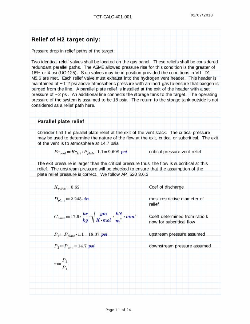
Relief of H2 target only:
Pressure drop in relief paths of the target:
Two identical releif valves shall be located on the gas panel. These reliefs shall be considered redundant parallel paths. The ASME allowed pressure rise for this condition is the greater of 16% or 4 psi (UG-125). Stop valves may be in position provided the conditions in VIII D1 M5.6 are met. Each relief valve must exhaust into the hydrogen vent header. This header is maintained at ~1-2 psi above atmospheric pressure with an inert gas to ensure that oxegen is purged from the line. A parallel plate relief is installed at the exit of the header with a set pressure of ~2 psi. An additional line connects the storage tank to the target. The operating pressure of the system is assumed to be 18 psia. The return to the stoage tank outside is not considered as a relief path here.
Parallel plate relief
Consider first the parallel plate relief at the exit of the vent stack. The critical pressure may be used to determine the nature of the flow at the exit, critical or subcritical. The exit of the vent is to atmosphere at 14.7 psia
≔Pcvent =⋅⋅RcH2 Pplate 1.1 9.698 critical pressure vent relief
The exit pressure is larger than the critical pressure thus, the flow is subcritical at this relief. The upstream pressure will be checked to ensure that the assumption of the plate relief pressure is correct. We follow API 520 3.6.3
≔Kvalve 0.62 Coef of discharge
≔Dplate ⋅2.245 most restrictive diameter of relief
≔Casme ⋅⋅⋅⋅17.9 ―‾‾‾‾‾‾‾―――
⋅――
2
2 Coeff determined from ratio k now for subcritical flow
≔P1 =⋅Pplate 1.1 18.37 upstream pressure assumed
≔P2 =Patm 14.7 downstream pressure assumed
≔r ―P2
P1
Page 11 of 24

02/07/2013TGT-CALC-401-001
≔F2 =
‾‾‾‾‾‾‾‾‾‾‾‾‾‾‾‾‾‾‾‾‾
⋅⋅―――kH2
−kH2 1r
―2
kH2
⎛⎜⎜⎝――――
−1 r――
−kH2 1
kH2
−1 r
⎞⎟⎟⎠
0.887 subcritical flow coeff
the required area for the given mass discharge is
≔Areq =⋅――――⋅dmH2 Casme
⋅F2 Kvalve
‾‾‾‾‾‾‾‾‾‾‾‾‾‾‾――――――
Troom
⋅⋅MH2 P1⎛⎝ −P1 P2
⎞⎠0.307 2
the required lift of the plate would be
≔hlift =―――Areq
⋅ Dplate
0.044
The estimated force on the plate is
≔Fplate =⋅⋅⎛⎝ −P1 Patm⎞⎠ ―――
Dplate2
414.527
Springs must be chosen to provide the given lift height for this force.
Vent stack pressure drop
Vent stack estimate based on placement of tanks and vent at 100' from building. This is a convient place. NFPA requirement of 40 ft from all buildings and AC vents. Storage tanks to be paced with vent. Flex lines will be needed to connect the vent to the gas panel relief and the relief at the top of the target. The length of these lines is assumed to be 20 ft. The line is assumed to be American BOA Parwrap 1.5" nom hose.
≔Lvent ⋅200 Length of hard vent pipe
≔Dod ⋅2.375 2 in pipe nom OD
≔twall ⋅0.065 wall thickness for 2" Sch 5 S pipe
≔IDvent −Dod twall ID of vent pipe
≔Avent =――――⋅ IDvent
2
40.003 2 cross area of vent stack
Page 12 of 24

02/07/2013TGT-CALC-401-001
≔Tvent ⋅300 ≔Pvent ⋅1.1 Pplate temp and pressure in vent
≔vvent =――――――――dmH2
⋅ρH2⎛⎝ ,Tvent Pvent
⎞⎠ Avent
28.239 ― velocity in vent line
Reynolds number at relief; flow is turbulent
≔Revent =――――――――――⋅⋅ρH2
⎛⎝ ,Tvent Pvent⎞⎠ vvent IDvent
μH2300
⋅1.893 104
≔fvent =――――⋅0.032
―1
3
IDvent
―1
3
0.024 Weymouth friction factor
≔Kvent ⋅fvent ―――Lvent
IDvent
resistance coef for vent
≔Nbends 8 estimated number of street elbows in vent stack
≔Kelbows =⋅60 fvent 1.452 worst case factor for elbows
Flex lines to insertion cart:
effective length of flex line for insertion cart actual length is 20 ft. The factor of 3 results from measurements of pressure drop in corregated flex hose
≔Lflex ⋅(( ⋅20 )) 3
≔IDflex ⋅1.5 ID of flex lines
≔Aflex ⋅ ―――IDflex
2
4cross area of flex
≔fflex =――――⋅0.032
―1
3
IDflex
―1
3
0.028 Weymouth friction factor
Page 13 of 24

02/07/2013TGT-CALC-401-001
≔vflex =―――――――dmH2
⋅ρH2⎛⎝ ,Tvent Pvent
⎞⎠ Aflex
66.971 ― velocity in flex line
≔Kflex =⋅fflex ――Lflex
IDflex
13.418 resistance coef for flex line
≔ΔPflex =⋅⋅Kflex ρH2300 ――vflex
2
20.729 pressure loss in flex line
≔β ―――IDflex
IDvent
Resistance factor for enlargement from flex to main≔Ken =―――
⎛⎝ −1 β2 ⎞⎠2
β41.881
head loss from height of vent stack
≔hstack ⋅70 this is negligible
≔ΔPstack =⋅⋅hstack ρH2⎛⎝ ,Tvent Pvent
⎞⎠ 0.003
total pressure loss in vent line from relief valve exit to parallel plate
≔ΔPvent =+⋅⋅⎛⎝ +Kvent ⋅Nbends Kelbows⎞⎠ ρH2
⎛⎝ ,Tvent Pvent⎞⎠ ――
vvent2
2ΔPflex 0.946
First stage relief (ASME Relief Valve):
The pressure at the back side of the first stage relief is
≔P2 =+⋅Pplate 1.1 ΔPvent 19.316 pressure on upstream of 1st stage relief valve
≔P1 =⋅Pset 1.1 33 upstream pressure assumed
≔Pc1 =⋅⋅RcH2 Pset 1.1 17.422 critical pressure at 1st stage relief
Page 14 of 24

02/07/2013TGT-CALC-401-001
The flow at the 1st stage relief will be subcritical
≔r ―P2
P1
ratio of outlet to inlet pressures
≔F2 =
‾‾‾‾‾‾‾‾‾‾‾‾‾‾‾‾‾‾‾‾‾
⋅⋅―――kH2
−kH2 1r
―2
kH2
⎛⎜⎜⎝――――
−1 r――
−kH2 1
kH2
−1 r
⎞⎟⎟⎠
0.747 subcritical flow coeff
≔Kvalve ⋅0.878 0.9 Coef of discharge
≔Dplate ⋅2.245 most restrictive diameter of relief
≔Casme ⋅⋅⋅⋅17.9 ―‾‾‾‾‾‾‾―――
⋅――
2
2 Coeff determined from ratio k now for subcritical flow
the required area for the given mass discharge is
≔Areq =⋅――――⋅dmH2 Casme
⋅F2 Kvalve
‾‾‾‾‾‾‾‾‾‾‾‾‾‾‾――――――
Troom
⋅⋅MH2 P1⎛⎝ −P1 P2
⎞⎠0.111 2
Relief valve:Based on the above a Flow Safe F85 Series relief valve 01-4167M-203 with viton seat will be more than adequate for our needs. The pressure at the entrance of the relief is assumed to be.
≔Prelief =⋅1.1 Pset 33
Page 15 of 24

02/07/2013TGT-CALC-401-001
Piping from cell to relief
For all piping from the main relief line tee, located below the condenser, to the relief at the panel the temperatureand pressure of the H2 is assumed to be the same as that at the relief valve. This is a very conservative assumption. Thus the density and volumetric flow are
≔ρ =ρH2⎛⎝ ,Tvent Prelief
⎞⎠ 0.184 ――3
≔dVH2 =――dmH2
ρ0.043 ――
3
Piping from Target Top flange to Relief Valve:
The relief valve will be mounted on the gas panel. The gas panel is assumed to be 10 ft from the top of the target by hose. This connection is assumed to be made using 1" nominal flex hose. These lines are named the connection lines. There is also an abrupt enlargement from 3/4" tube to 1 in ID. The flow must pass through a 1" Tee branch to reach the relief valve.
Flex lines:
effective length of flex line for connection lines from gas panel to target is 6 ft. The factor of 3 results from measurements of pressure drop in corregated flex hose
≔Lcl ⋅(( ⋅10 )) 3
≔IDcl ⋅1 ID of flex lines
≔Acl ⋅ ――IDcl
2
4cross area of flex
≔fcl =――――⋅0.032
―1
3
IDcl
―1
3
0.032 Weymouth friction factor
≔vcl =――dVH2
Acl
83.881 ― velocity in flex line
Page 16 of 24

02/07/2013TGT-CALC-401-001
≔Kcl =⋅fcl ――Lcl
IDcl
11.52 resistance coef for flex line
≔ΔPcl =⋅⋅Kcl ρH2300 ――vcl
2
20.982 pressure loss in flex line
Gas panel:
≔Lgp(( ⋅2 )) estimated length of gas
panel tubing to valve≔twall ⋅0.035
≔OD ⋅1
≔IDgp −OD ⋅2 twall ID of gas panel return tube
≔Agp ⋅ ――IDgp
2
4cross area of return tube
≔fgp =――――⋅0.032
―1
3
IDgp
―1
3
0.033 Weymouth friction factor
≔vgp =――dVH2
Agp
96.983 ― velocity in return tube
≔Kgp =⋅fgp ――Lgp
IDgp
0.846 resistance return
≔Ktee ⋅60 fgp resistance of tee branch
≔Kelbow ⋅60 fgp resistance of elbow at tgt top
≔ΔPgp =⋅⋅⎛⎝ ++Ktee Kelbow Kgp⎞⎠ ρ ――
vgp2
20.6
Page 17 of 24

02/07/2013TGT-CALC-401-001
Enlargement from 3/4 tube to 1" id flex
≔d1 ⋅(( −0.75 ⋅2 0.035)) ID of target return line at top of target
≔A1 =⋅―4
d12 0.363 2 cross area
≔v1 =――dVH2
A1
181.403 ― velocity at tgt top
≔d2 ⋅1 ID of flex
≔β ―d1
d2
≔Ken =―――⎛⎝ −1 β2 ⎞⎠
2
β41.352
≔ΔPen =⋅⋅Ken ρ ――vgp
2
20.17
Total pressure drop on tgt external return to relief valve
≔ΔPext =++ΔPen ΔPgp ΔPcl 1.751
Page 18 of 24

02/07/2013TGT-CALC-401-001
Internal target piping pressure loss:
Escaping gas from the cell must pass through several piping sections prior to reaching the valve. Some of these sections are inside the OVC and are cold for some portion. From the cell to the tee below the condenser, the escaping gas is assumed to have a temperature of 23.4K and pressure of 33 psi. From the relief tee to the target top flange the assume temperature is 300 K. The worst case failure mode would be for the condenser to relief tee to be blocked while the target vacuum is lost. All flow must then pass through the return side plumbing from the cell.
From relief tee to target top flange
≔Lret ⋅3 Length of return lines
≔Dret ⋅0.75 OD of supply and return lines
≔Dtee ⋅0.5 nominal diameter of relief tee
≔twall ⋅0.035 wall thickness of lines
≔IDret −Dret ⋅2 twall ID of supply and return lines
≔IDtee −Dtee ⋅2 twall ID of lines at tee
≔Aret =⋅ ―――IDret
2
40.363 2 cross area of return
≔fret =――――⋅0.032
―1
3
IDret
―1
3
0.036 Weymouth friction factor (conservative)
≔vret =――dVH2
Aret
181.403 ― velocity in return line
≔Kret =⋅fret ――Lret
IDret
1.927 resistance coef for return line
≔Kelbow =⋅fret 60 2.183 resistance coef for miter bends in line assume 2
≔β ――IDtee
IDret
Page 19 of 24
02/07/2013TGT-CALC-401-001
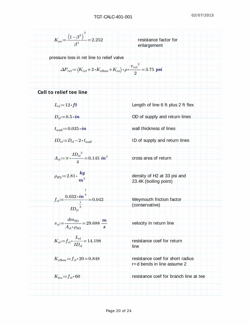
≔Ken =―――⎛⎝ −1 β2 ⎞⎠
2
β42.252 resistance factor for
enlargement
pressure loss in ret line to relief valve
≔ΔPret =⋅⋅⎛⎝ ++Kret ⋅2 Kelbow Ken⎞⎠ ρ ――
vret2
23.75
Cell to relief tee line
≔Lrl ⋅12 Length of line 6 ft plus 2 ft flex
≔Drl ⋅0.5 OD of supply and return lines
≔twall ⋅0.035 wall thickness of lines
≔IDrl −Drl ⋅2 twall ID of supply and return lines
≔Arl =⋅ ――IDrl
2
40.145 2 cross area of return
≔ρH2 ⋅2.81 ――3
density of H2 at 33 psi and 23.4K (boiling point)
≔frl =――――⋅0.032
―1
3
IDrl
―1
3
0.042 Weymouth friction factor (conservative)
≔vrl =―――dmH2
⋅Arl ρH2
29.688 ― velocity in return line
≔Krl =⋅frl ――Lrl
IDrl
14.198 resistance coef for return line
≔Kelbow =⋅frl 20 0.848 resistance coef for short radius r=d bends in line assume 2
≔Ktee ⋅frl 60 resistance coef for branch line at tee
Page 20 of 24

02/07/2013TGT-CALC-401-001
pressure loss in ret line to relief valve
≔ΔPrl =⋅⋅⎛⎝ ++Krl ⋅2 Kelbow Ktee⎞⎠ ρH2 ――
vrl2
23.311
loss from cell legs
≔Lleg ⋅5 Length of leg
≔Dleg ⋅0.375 OD of leg
≔twall ⋅0.035 wall thickness of line
≔IDleg −Dleg ⋅2 twall ID of leg
≔Aleg =⋅ ―――IDleg
2
40.073 2 cross area of leg
≔ρH2 ⋅2.81 ――3
density of H2 at 33 psi and 23.4K (boiling point)
≔fleg =――――⋅0.032
―1
3
IDleg
―1
3
0.048 Weymouth friction factor (conservative)
≔vleg =―――dmH2
⋅Aleg ρH2
59.009 ― velocity in leg
≔Kleg =⋅fleg ――Lleg
IDleg
0.779 resistance coef for leg
≔β ――IDleg
IDrl
≔Ken =―――⎛⎝ −1 β2 ⎞⎠
2
β40.975 resistance factor for
enlargement
≔ΔPleg =⋅⋅⎛⎝ +Kleg Ken⎞⎠ ρH2 ――
vleg2
21.245
Page 21 of 24

02/07/2013TGT-CALC-401-001
Flow must exit the cell first through a tapered anulus that preceeds the leg. To estimate this flow the hydraulic diameter will be used. the flow is from the cell and condenser only. The entrance to the leg tube is also acounted for
annulus exit from cell
≔Din =―――――――(( +⋅0.738 ⋅0.906 ))
20.822 avg small diameter of anulus
≔Dout =⋅(( +0.479 0.516)) 0.995 avg large diameter of anulus
≔Pin ⋅Din average perimeter inner
≔Pout ⋅Dout average perimeter outer
≔A =⋅―4
⎛⎝ −Dout2 Din
2 ⎞⎠ 0.247 2 flow area
≔Dh =――――⋅4 A
⎛⎝ +Pin Pout⎞⎠
0.173 hydraulic diameter
≔ρH2 ⋅2.81 ――3
density of H2 at 33 psi and 23.4K (boiling point)
≔fcell =――――⋅0.032
―1
3
Dh
―1
3
0.057 Weymouth friction factor (conservative)
≔vcell =―――――+dmcond dmcell
⋅⋅ ――Dh
2
4ρH2
113.446 ― velocity in cell annulus
≔Kcell =⋅fcell ―――⋅2.8
Dh
0.929 resistance coef for leg
≔β =――IDleg
Dh
1.763 ratio for contraction to 3/8 tube
Page 22 of 24

02/07/2013TGT-CALC-401-001
≔Kcont ⋅0.5 ―――⎛⎝ −1 β2 ⎞⎠
β4
estimate of pressure drop in cell annulus and exit
≔ΔPcell =⋅⋅⎛⎝ +Kcell Kcont⎞⎠ ρH2 ――
vcell2
22.152
Total maximum cell pressure:
Max total cell absolute pressure from the above calculations and assumptions
≔Pcell =+++++ΔPcell ΔPret ΔPrl ΔPleg Prelief ΔPext 45.209
Loss in supply line
≔Lsup ⋅12 Length of leg 6 ft + 2 ft of flex
≔Dsup ⋅0.25 OD of leg
≔twall ⋅0.035 wall thickness of line
≔IDsup −Dsup ⋅2 twall ID of leg
≔Asup =⋅ ―――IDsup
2
40.025 2 cross area of leg
≔ρH2 ⋅2.81 ――3
density of H2 at 33 psi and 23.4K (boiling point)
≔fsup =――――⋅0.032
―1
3
IDsup
―1
3
0.057 Weymouth friction factor (conservative)
≔vsup =―――dmcond
⋅Asup ρH2
64.629 ― velocity in leg
L
Page 23 of 24

02/07/2013TGT-CALC-401-001
≔Ksup =⋅fsup ――Lsup
IDsup
45.34 resistance coef for leg
≔β ――IDsup
IDleg
≔Ken =―――⎛⎝ −1 β2 ⎞⎠
β45.372 resistance factor for
enlargement
≔Kent 0.5 resistance coef for cond pipe entrance
The maximum pressure in the condenser for the worst case failure mode where the main relief connection is plugged.
≔Pcond =+Pcell ⋅⋅⎛⎝ ++Ken Kent Ksup⎞⎠ ρH2 ――
vsup2
288.799
the dominant loss is in the 1/4 in line as expected
≔ΔPsup =⋅⋅Ksup ρH2 ――vsup
2
238.591
Page 24 of 24