th semester - about us syllabus 4th... · floyd, “electronic devices”, pearson education, 9th...
TRANSCRIPT

1
4TH
SEMESTER
2
COURSE NAME: LINEAR CONTROL SYSTEMS
COURSE CODE: EC-14401
Internal Marks: 40 L T P
External Marks: 60 3 1 -
Numerical & Design Problems Content: 50%-60%
Note: The Question paper shall have three sections:
Section A shall consist of one question with 10 sub-questions of two (02) marks each. Section B
shall consist of five questions of five (05) marks each, out of which four questions are required to
be attempted by the candidate. Section C shall consist of three questions of ten (10) marks each,
out of which two questions are required to be attempted by the candidate. Any question of
Section C may be sub–divided (if required) into two parts of five (05) marks each.
Course Outcomes
On successful completion of this course, the students should be able to:
CO1 Recognize and explain different types of control system.
CO2 Find the transfer function of a control system using block diagram and signal flow
graph techniques.
CO3 Analyze the time domain behaviour of second and higher order systems.
CO4 Find out system stability using Routh Hurwitz’s criteria and root locus technique.
CO5 Analyse the frequency domain behaviour of the system using bode plot and Nyquist
criteria.
CO6 Use compensating techniques to design stable network.
CO7 Explain the working of various control system components such as error detectors,
synchros, potentiometers etc.
Syllabus:
Unit 1. Introductory Concepts
Plant, Systems, Servomechanism, regulating systems, disturbances, Open loop control system,
closed loop control systems, linear and non-linear systems, time variant & invariant, continuous
and sampled data control systems, Block diagrams, some illustrative examples.
3
Unit 2. Modelling
Formulation of equation of linear electrical, mechanical, thermal, pneumatic, hydraulic system,
electrical, mechanical analogies, Transfer function, Block diagram representation, Signal flow
graphs and associated algebra, characteristics equation.
Unit 3. Time domain analysis
Typical test–input signals, Transient response of first and second order systems, Time domain
specifications, Dominant closed loop poles of higher order system, Steady state error and
coefficients, pole- zero location and stability, Routh-Hurwitz Criterion.
Unit 4. Root Locus Technique
The extreme points of the root loci for positive gain, Asymptotes to the loci, Breakaway points,
intersection with imaginary axis, location of roots with given gain, sketch of the root locus plot.
Unit 5. Frequency Domain Analysis
Closed loop frequency response, Bode plots, stability and loop transfer function. Frequency
response specifications, Relative stability, Relation between time and frequency response for
second order systems, Log. Magnitude versus Phase angle plot, Nyquist criterion for stability.
Unit 6. Compensation
Necessity of compensation, series and parallel compensation, compensating networks,
applications of lag and lead- compensation.
Unit 7. Control Components
Error detectors – potentiometers and synchros, servo motors, ac and dc techno generators,
magnetic amplifiers.
Text Books
1. B. S. Manke, “Linear Control Systems”, Khanna Publishers, 11th
Edition, 2012.
2. I. J. Nagrath and M. Gopal, “Control System Engineering”, Wiley Eastern Ltd, 3rd
Edition,
2000.
4
Reference Books and Other Resources
1. R. C. Dorf and R. H. Bishop, “Modern Control System”, Addison –Wesley, Pearson
Education, 8th
Edition, 2004.
2. K. Ogata, “Modern Control Engineering”, Prentice Hall, 5th
Edition, 2010.
3. B. C. Kuo, “Automatic Control System”, Prentice Hall, 7th
Edition, 2000.
4. S. Janardhanan and Y. Singh, “Modern Control Engineering”, Cengage Learning, 2010.
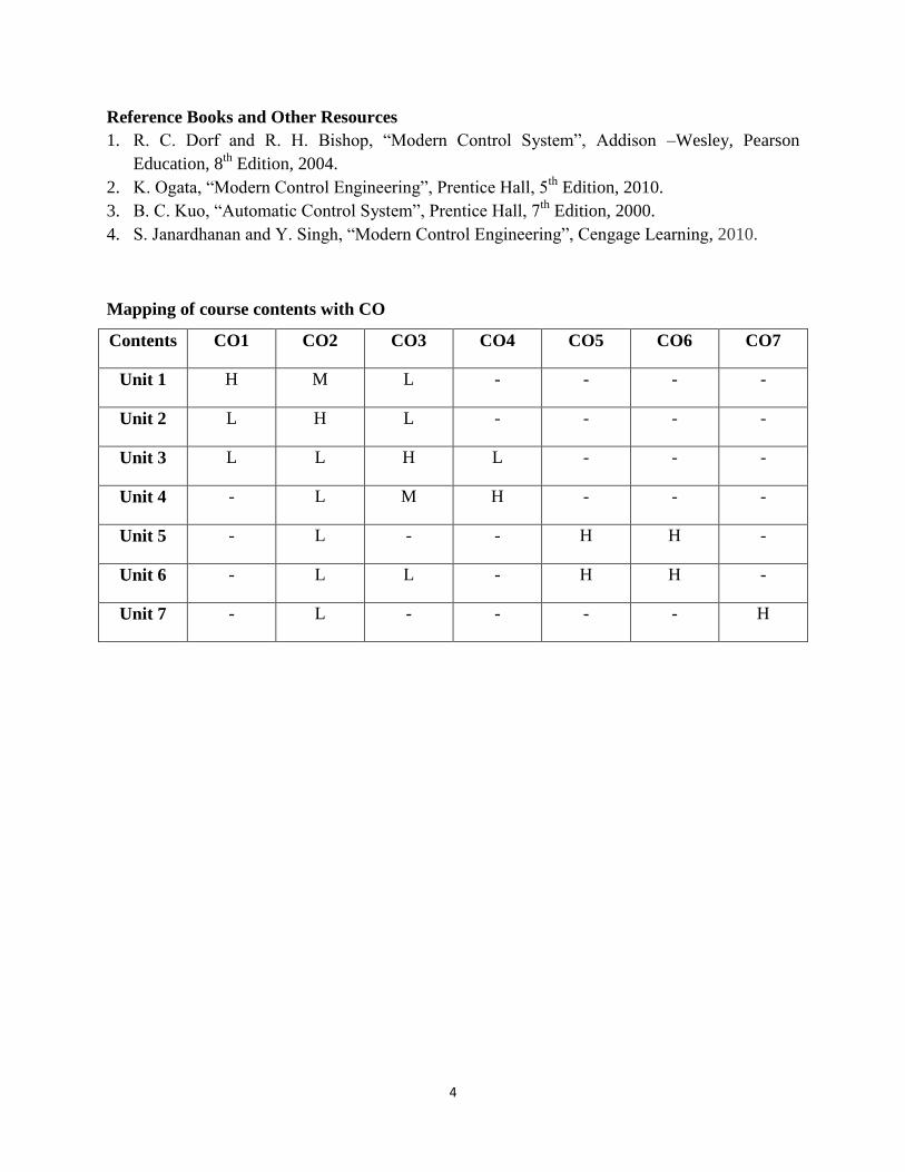
Mapping of course contents with CO
Contents CO1 CO2 CO3 CO4 CO5 CO6 CO7
Unit 1 H M L - - - -
Unit 2 L H L - - - -
Unit 3 L L H L - - -
Unit 4 - L M H - - -
Unit 5 - L - - H H -
Unit 6 - L L - H H -
Unit 7 - L - - - - H
5
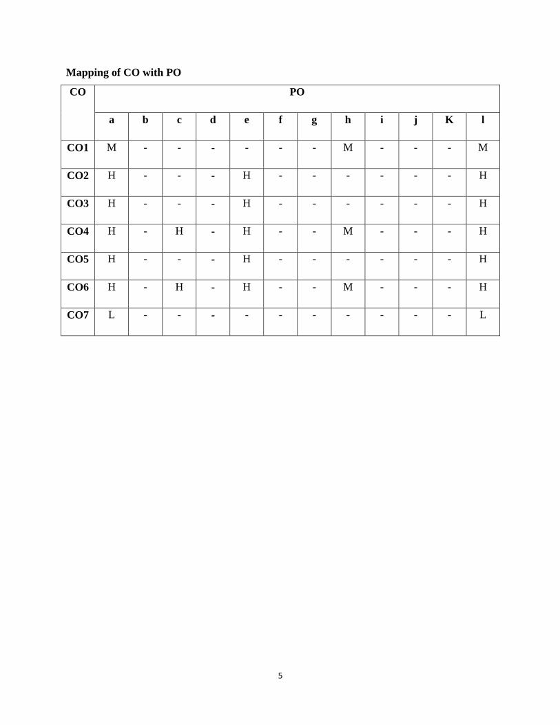
Mapping of CO with PO
CO PO
a b c d e f g h i j K l
CO1 M - - - - - - M - - - M
CO2 H - - - H - - - - - - H
CO3 H - - - H - - - - - - H
CO4 H - H - H - - M - - - H
CO5 H - - - H - - - - - - H
CO6 H - H - H - - M - - - H
CO7 L - - - - - - - - - - L

6
COURSE NAME: ELECTRONICS DEVICES & CIRCUITS-II
COURSE CODE: EC-14402
Internal Marks: 40 L T P
External Marks: 60 3 1 -
Numerical & Design Problems Content: 20%-30%
Note: The Question paper shall have three sections:
Section A shall consist of one question with 10 sub-questions of two (02) marks each. Section B
shall consist of five questions of five (05) marks each, out of which four questions are required to
be attempted by the candidate. Section C shall consist of three questions of ten (10) marks each,
out of which two questions are required to be attempted by the candidate. Any question of
Section C may be sub–divided (if required) into two parts of five (05) marks each.
Course Outcomes
On successful completion of this course, the students should be able to:
CO1 Comprehend the significance of transistor coupling and explain various coupling
techniques.
CO2 Explain the concept of tuned amplifiers.
CO3 Classify power amplifiers and calculate efficiency of each amplifier.
CO4 Analyze effect of feedback in amplifiers.
CO5 Describe working of various RC and LC oscillators.
CO6 Analyze operation of transistor in terms of T and Pi model at high frequency.
Syllabus:
Unit 1. Multistage Amplifiers
Coupling of transistor amplifiers, frequency response of coupled amplifiers, Types of coupling:
RC coupling, Transformer coupling, direct coupling, Cascode amplifier, Darlington amplifier.
Tuned Amplifiers: single tuned, double tuned and stagger tuned amplifiers.
Unit 2. Large Signal Amplifiers
Class A direct coupled with resistive load, Transformer coupled with resistive load, harmonic
distortion, variation of output power with load, push-pull amplifiers, operation of Class A push-
7
pull amplifier, Class B push-pull amplifier, crossover distortion, Class AB push-pull amplifier,
Transistor phase inverter, Complementary- symmetry amplifier.
Unit 3. Feedback in Amplifiers
Types of feedback, effect of negative feedback on gain, input impedance, output impedance,
bandwidth, stability, distortion and frequency response, voltage series, current series, voltage
shunt, current shunt feedback circuits and their analysis.
Unit 4. Oscillators
Sinusoidal oscillators, Criterion for oscillation, Different types of oscillators: RC Phase Shift,
Wien Bridge, Hartley, Colpitt, Crystal Oscillators and Derivation of frequency for these
oscillators.
Unit 5. High Frequency Transistor
High frequency T model, common base short circuit current frequency response, alpha cutoff
frequency, common emitter short circuit current frequency response, hybrid pi CE transistor
model, hybrid pi conductance in terms of low frequency h parameters, CE short circuit current
gain obtained with hybrid pi model, current gain with resistive load.
Text Books:
1. J. Millman, C. Halkias and C. D. Parikh, “Integrated Electronics: Analog and Digital
Circuits and Systems”, McGraw Hill Education, 2nd
Edition, 2010.
2. R. Boylested and L. Nashelsky, “Electronic Devices and Circuit Theory”, Prentice Hall
of India, 10th
Edition, 2009.
Reference books and other resources:
1. S. Salivahanan, N. Suresh Kumar and A. Vallavaraj, “Electronic Devices and Circuits”,
Tata McGraw Hill, 2nd
Edition, 2011.
2. A. Malvino and D. J. Bates, “Electronic Principles”, Tata McGraw-Hill, 7th
Edition,
2007.
3. T. L. Floyd, “Electronic Devices”, Pearson Education, 9th
Edition, 2012.
4. J. Millman, C. C. Halkias and S. Jit, “Electronic Devices and Circuits”, Tata McGraw-
Hill, 3rd
Edition, 2010.
8
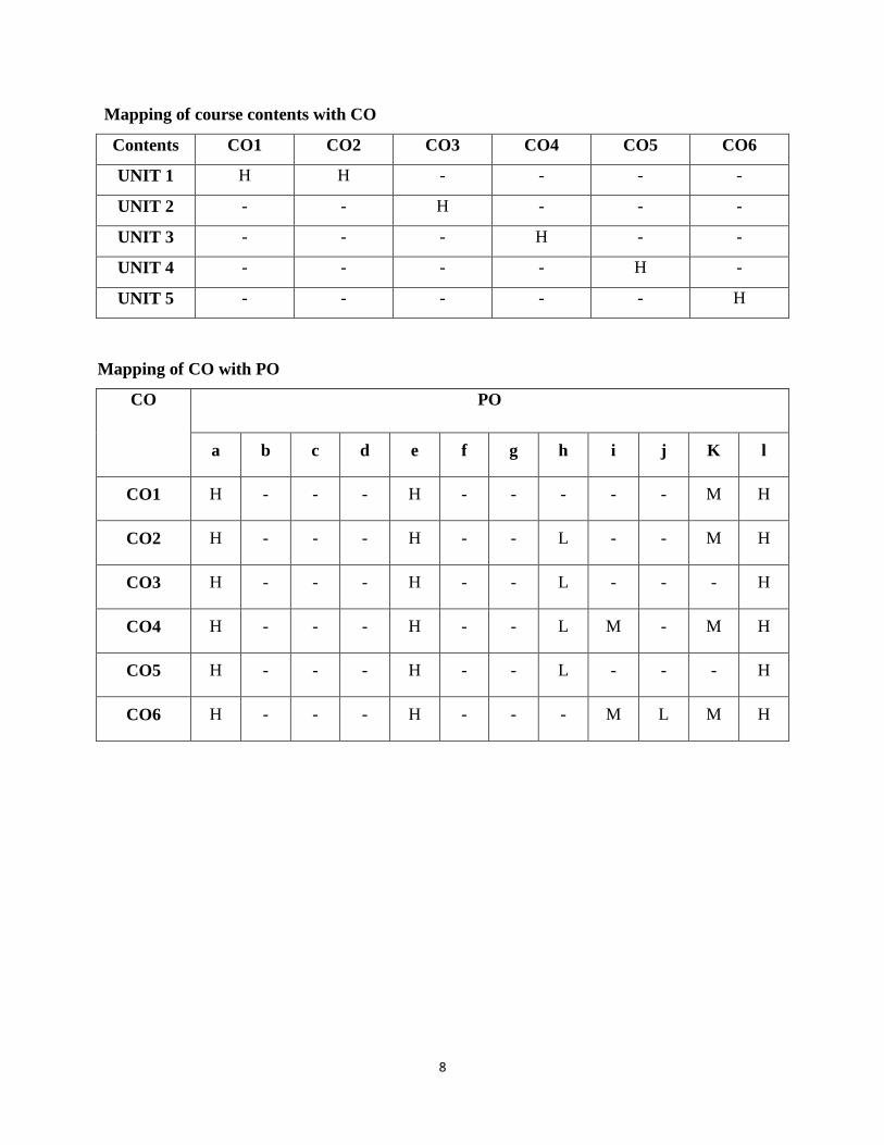
Mapping of course contents with CO
Contents CO1 CO2 CO3 CO4 CO5 CO6
UNIT 1 H H - - - -
UNIT 2 - - H - - -
UNIT 3 - - - H - -
UNIT 4 - - - - H -
UNIT 5 - - - - - H
Mapping of CO with PO
CO PO
a b c d e f g h i j K l
CO1 H - - - H - - - - - M H
CO2 H - - - H - - L - - M H
CO3 H - - - H - - L - - - H
CO4 H - - - H - - L M - M H
CO5 H - - - H - - L - - - H
CO6 H - - - H - - - M L M H

9
COURSE NAME: SIGNALS AND SYSTEMS
COURSE CODE: EC-14403
Internal Marks: 40 L T P
External Marks: 60 3 1 -
Numerical & Design Problems Content: 40%-50%
Note: The Question paper shall have three sections:
Section A shall consist of one question with 10 sub-questions of two (02) marks each. Section B
shall consist of five questions of five (05) marks each, out of which four questions are required to
be attempted by the candidate. Section C shall consist of three questions of ten (10) marks each,
out of which two questions are required to be attempted by the candidate. Any question of
Section C may be sub–divided (if required) into two parts of five (05) marks each.
Course Outcomes
On successful completion of this course, the students should be able to:
CO1 Classify signals and systems & perform basic operations like scaling, shifting, folding
etc. on them.
CO2 Represent continuous-time and discrete-time signals in the form of Fourier series and
Fourier Transform.
CO3 Calculate the response of Continuous-time Linear Time Invariant Systems.
CO4 Explain the behavior of random signals in terms of probability functions.
CO5 Comprehend different noise sources and analyze their impact on system performance
Syllabus:
Unit 1. Classification of Signals and Systems
Introduction, Elementary signals in continuous and discrete domain, Operations on Signals:
scaling, shifting and folding. Classification of Continuous-time and Discrete-time signals,
Classification of Continuous-time and Discrete-time systems.
Unit 2. Analysis of Continuous-time and Discrete-time signals
Representation of Continuous-time and discrete-time signals using Fourier series: Trigonometric
Fourier series, Polar Form of Fourier series and Exponential Fourier Series, concept of negative

10
frequency, Properties of Fourier Series, Aperiodic Continuous-time and discrete-time signal
representation using Fourier Transform, Properties of Fourier Transform, Fourier Transform of
Periodic Power Signals, Power Spectral Density, Energy Spectral Density, Parseval’s Theorem
and correlation.
Unit 3. Continuous-Time Linear Time Invariant Systems
Definitions and Properties of LTI Systems, Impulse and step response, Convolution integral,
Transfer function.
Unit 4. Random Signal Theory
Introduction to Probability Theory, Definitions, Probability of Random Events, Joint and
Conditional Probability, Probability Mass Function, Probability Density Function, Statistical
Averages, Examples of Probability Density Functions, Transformation of Random Variables,
Random Process: Stationary and Non-stationary, Ergodicity.
Unit 5. Signal Transmission through Systems
Sampling Theorem, Thermal Noise, Shot noise, Partition noise, Flicker noise, Gaussian Noise,
Noise in Bipolar Junction Transistors (BJTs), FET noise. Equivalent input noise, Signal to Noise
Ratio (SNR), Noise Temperature, Noise equivalent Bandwidth, Noise Figure, Experimental
determination of Noise Figure, Matched Filter.
Text Books:
1. S. Haykins and B. V. Veen, “Signals and Systems”, John Wiley & Sons, 2nd
Edition,
2008.
2. S. Haykin, “Communication Systems”, John Wiley & Sons, 3rd
Edition, 2008.
Reference books and other resources:
1. H. P. Hsu, “Signals and Systems”, McGraw Hill Education Pvt. Ltd., 2nd
Edition, 2008.
2. A. V. Oppenheim, S. Wilsky and S. H. Nawab, “Signals and Systems”, Pearson
Education, 2007.
3. M. J. Roberts, “Signals and Systems: Analysis using Transform Methods and
MATLAB”, Tata McGraw-Hill, 2nd
Edition, 2012.
4. D. Sundararajan, “A Practical Approach to Signals and Systems”, John Wiley & Sons,
2008.

11
5. S. Ghosh, “Signals and Systems”, Pearson Education, 2006.
6. W.V. Etten, “Introduction to Random Signals and Noise”, John Wiley & Sons, 2005.
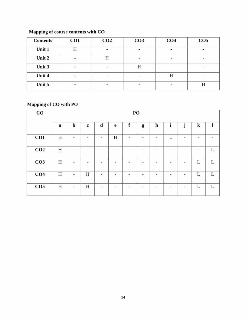
Mapping of course contents with CO
Contents CO1 CO2 CO3 CO4 CO5
UNIT 1 H - - -
UNIT 2 - H - - -
UNIT 3 - - H - -
UNIT 4 - - - H -
UNIT 5 - - - - H
Mapping of CO with PO
CO PO
a b c d e f g h i j k l
CO1 H - - - M - - - - - - H
CO2 H - - - M - - - - - M H
CO3 H - - - M - - - - - - H
CO4 H - - - M - - - M M M H
CO5 H - - - M - - L M M - H

12
COURSE NAME: ELECTROMAGNETIC FIELD THEORY
COURSE CODE: EC-14404
Internal Marks: 40 L T P
External Marks: 60 3 1 -
Numerical & Design Problems Content: 30%-40%
Note: The Question paper shall have three sections:
Section A shall consist of one question with 10 sub-questions of two (02) marks each. Section B
shall consist of five questions of five (05) marks each, out of which four questions are required to
be attempted by the candidate. Section C shall consist of three questions of ten (10) marks each,
out of which two questions are required to be attempted by the candidate. Any question of
Section C may be sub–divided (if required) into two parts of five (05) marks each.
Course Outcomes
On successful completion of this course, the students should be able to:
CO1 Apply the Maxwell’s equations to solve boundary conditions in different media.
CO2 Describe the concept of electromagnetic wave propagation and its sinusoidal variation in
different media.
CO3 Analyze the characteristics of guided waves in parallel planes.
CO4 Explain the propagation of waves in rectangular and circular waveguides.
CO5 Describe and analyze parallel plane transmission lines with Smith charts.
Syllabus:
Unit 1. Introduction to Time varying fields
Maxwell's equations in differential and integral forms, Concept of displacement current and
conduction current, Boundary conditions.
Unit 2. Electromagnetic Waves
Wave equation and its solution in different media, Plane wave, Sinusoidal time variations,
Polarization, Reflection of waves by perfect dielectrics and by perfect insulators, Surface
impedance, Poynting theorem and Poynting vector.

13
Unit 3. Guided Waves
Waves between parallel planes, TE, TM waves and their characteristics, TEM waves, Velocities
of propagation, Attenuation in parallel plane guides, Wave impedance.
Unit 4. Wave Guides
Rectangular and circular wave guides, TE and TM waves in rectangular waveguides,
Impossibility of TEM wave in wave guides, Wave impedance and Characteristic impedance,
Transmission line analogy for wave guides, Attenuation factor of wave guides.
Unit 5. Transmission Lines
Circuit representation of parallel plane transmission lines, Parallel plane transmission line with
losses, Lossless line, Low loss RF and UHF transmission lines, Distortionless line, Transmission
line charts-impedance matching.
Text Books:
1. E. C. Jordan & K. G. Balmain, Electromagnetic Waves and Radiating Systems, 2nd
edition , PHI ,2011
2. P. V. Gupta, Introductory Course In Electromagnetic Fields, 3rd
edition, Dhanpat Rai &
Sons Company Limited.
Reference Books / Study material:
1. W. H. Hayt & J.A. Buck, Engineering Electromagnetics, 8th
edition, TATA McGraw-
Hill, 2014.
2. W. H. Hayt & J.A. Buck, Problem and solutions in Electromagnetics, 8th
edition TATA
McGraw-Hill, 2014.
3. John Krauss, Electromagnetics and applications, 4th
edition ,TATA McGraw-Hill, 2010.
4. Matthew, N. O. Sadiku, Elements of Engineering Electromagnetics, 4th edition,
Oxford University Press, 2007.
14
Mapping of course contents with CO
Contents CO1 CO2 CO3 CO4 CO5
Unit 1 H - - - -
Unit 2 - H - - -
Unit 3 - - H -
Unit 4 - - - H -
Unit 5 - - - - H
Mapping of CO with PO
CO PO
a b c d e f g h i j k l
CO1 H - - - H - - - L - - -
CO2 H - - - - - - - - - - L
CO3 H - - - - - - - - - L L
CO4 H - H - - - - - - - L L
CO5 H - H - - - - - - - L L
15
COURSE NAME: DIGITAL ELECTRONICS
COURSE CODE: EC-14405
Internal Marks: 40 L T P
External Marks: 60 3 1 -
Numerical & Design Problems Content: 40%-50%
Note: The Question paper shall have three sections:
Section A shall consist of one question with 10 sub-questions of two (02) marks each. Section B
shall consist of five questions of five (05) marks each, out of which four questions are required to
be attempted by the candidate. Section C shall consist of three questions of ten (10) marks each,
out of which two questions are required to be attempted by the candidate. Any question of
Section C may be sub–divided (if required) into two parts of five (05) marks each.
Course Outcomes
On successful completion of this course, the students should be able to:
CO1 Convert binary number from one system to another.
CO2 Describe the working of logic gates & circuits.
CO3 Minimize the logical expressions by choosing the appropriate method.
CO4 Design the combinational and sequential circuits for the given requirements.
CO5 Describe working of ADC and DAC.
CO6 Explain the characteristics & applications of semiconductor memories.
CO7 Describe the operation of various logic families.
Syllabus:
Unit 1. Number Systems and Binary Codes
Introduction, Number Systems: binary, octal and hexadecimal; Binary Operations: addition,
Subtraction, multiplication and division; Signed binary numbers, Subtractions using 1's and 2's
compliment, Binary Codes: BCD code and BCD additions, Excess 3 code, Gray code, ASCII
code.
16
Unit 2. Minimization of Logic Function
Logic Gates: OR, AND, NOT, NOR, NAND, EX-OR; Pin diagram and description of ICs of
logic gates, Boolean algebra, Basic theorem of Boolean algebra, Minimization using Boolean
algebra, Standard representations of logic functions, K-map representation of logic functions,
Minimization using K-map and Q-M method, Incompletely specified functions/Don’t care
Conditions.
Unit 3. Combinational Logic Circuits
Introduction, Combinational circuit design, Multiplexer, Implementation of combinational circuit
using multiplexer, Demultiplexer, Use of demultiplexer in combinational logic design, Adders,
Subtractors, use of adders as subtractors, Adder with look-ahead carry, Encoder, Decoder, Code
converters, Parity generator/checker, Digital comparators, BCD-to-7 segment display
decoder/driver.
Unit 4. Sequential Circuits
Introduction, Flip-Flops: working principles, types, applications; Shift registers: types, circuit
diagram, timing wave form and applications; Counters: types, working principles, design of
asynchronous and synchronous counter, counter design using state equations and state diagrams.
Unit 5. D/A and A/D Converters
Introduction, Digital to Analog Converters (DACs): types, working principles, specifications;
Analog to Digital Converters (ADCs): types, working principles, Specifications.
Unit 6. Semiconductor Memories
Introduction, Memory organization and operation, Classification and characteristics of
memories, Read-only memory, Read-Write memory, Content addressable memory, Charged
coupled device memory.
Unit 7. Digital Logic Families
Characteristics of Digital ICs, RTL, DCTL, DTL, TTL, ECL, CMOS logic families and their
types, Comparison of logic families.
17
Text Books:
1. R. P. Jain, “Modern Digital Electronics”, Tata McGraw–Hill, 4th
Edition, 2010.
Reference books and other resources:
1. T. L. Floyd, “Digital Fundamentals”, Pearson Education, 7th
Edition, 2002.
2. M. Mano, “Digital Design”, Pearson Education, 4th
Edition, 2008.
3. D. P. Leach and A. P. Malvino, “Digital Principles and Applications”, Tata McGraw Hill,
5th
Edition, 2003.
4. R. J. Tocci, N. S. Widmer, G. L. Moss, “Digital System-Principles and Applications”,
Pearson Education, 2002.
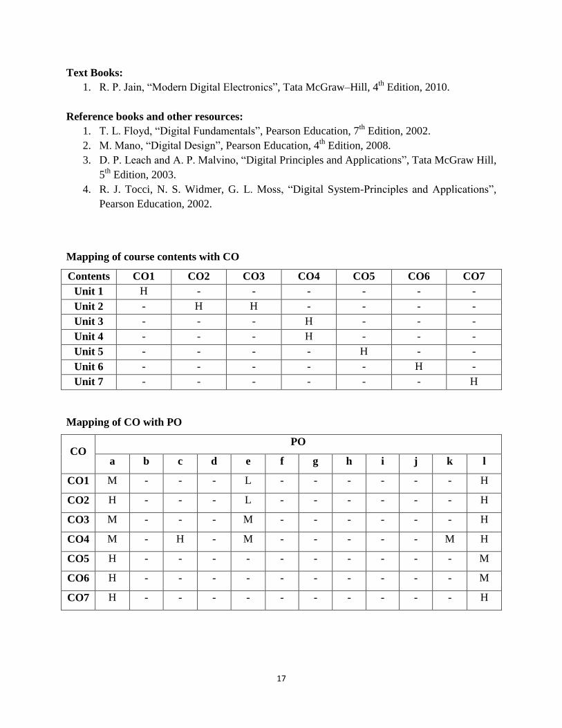
Mapping of course contents with CO
Contents CO1 CO2 CO3 CO4 CO5 CO6 CO7
Unit 1 H - - - - - -
Unit 2 - H H - - - -
Unit 3 - - - H - - -
Unit 4 - - - H - - -
Unit 5 - - - - H - -
Unit 6 - - - - - H -
Unit 7 - - - - - - H
Mapping of CO with PO
CO PO
a b c d e f g h i j k l
CO1 M - - - L - - - - - - H
CO2 H - - - L - - - - - - H
CO3 M - - - M - - - - - - H
CO4 M - H - M - - - - - M H
CO5 H - - - - - - - - - - M
CO6 H - - - - - - - - - - M
CO7 H - - - - - - - - - - H
18
COURSE NAME: PULSE WAVE SHAPING AND SWITCHING
COURSE CODE: EC-14406
Internal Marks: 40 L T P
External Marks: 60 3 1 -
Numerical & Design Problems Content: 30%-40%
Note: The Question paper shall have three sections:
Section A shall consist of one question with 10 sub-questions of two (02) marks each. Section B
shall consist of five questions of five (05) marks each, out of which four questions are required to
be attempted by the candidate. Section C shall consist of three questions of ten (10) marks each,
out of which two questions are required to be attempted by the candidate. Any question of
Section C may be sub–divided (if required) into two parts of five (05) marks each.
Course Outcomes
On successful completion of this course, the students should be able to:
CO1 Describe the working of different series and parallel RLC circuits.
CO2 Analysis the RC circuits for low and high pass filtering
CO3 Analyze the characteristics of clipping and clamping circuits.
CO4 Illustrate the switching characteristic of different devices.
CO5 Understand the negative resistance behavior of semiconductor devices.
CO6 Analyze voltage and current sweep circuits and identify methods to mitigate sweep errors.
Syllabus:
Unit 1. Introduction to Basic Elements and Waveforms
Passive and Active circuit elements, AC through inductor and capacitor, AC through Resistor-
inductor and resistor-capacitor in series, Series and parallel resonance circuit, Different input
signals, Average and RMS value.
Unit 2. Linear Wave Shaping
High pass and low pass circuits, Response to sine, step, pulse, square, exponential and ramp
inputs with different time constants, High pass as a differentiator, Low pass as an integrator,
Attenuators- response to step input, Compensated attenuator.

19
Unit 3. Non-Linear Wave Shaping
Diode clippers, Transistor clippers and two level clippers, Clamping circuits using diodes,
Practical clamping circuit, Clamping theorem, Comparators, Diode- differentiator comparator.
Unit 4. Switching Circuits
Diode and transistor as electronic switch, Switching times in diode and transistor, Bistable,
Monostable and Astable Multivibrators (both collector and emitter coupled), Symmetrical and
Unsymmetrical triggering, Schmitt trigger Circuits.
Unit 5. Negative Resistance Switching Circuits
Voltage controlled and current controlled negative resistance circuits, Negative-resistance
characteristics, Monostable, Bistable and Astable operations, Applications using tunnel diode
and UJT.
Unit 6. Sweep Circuits.
General features of a time base signal, Linearization of sweeps, Methods of generating time base
waveform, Bootstrap and Miller sweep circuits, principle of current sweeps.
Text Books:
1. Wave Generation and Shaping by L. Strauss, 3rd
Edition, TMH, 1995.
2. Pulse and Switching Circuits by Sanjeev Kumar, Dhanpat Rai & Company.
Reference books and other resources:
1. Pulse and Digital Switching Circuits by Milliman, Taub, Tata Mcgraw Hill.
2. Pulse and Digital Circuits by Mothiki S. Prakash Rao,Tata Mcgraw Hill.
3. Pulse & Digital Circuits, by Rao K, Pearson Education.
20
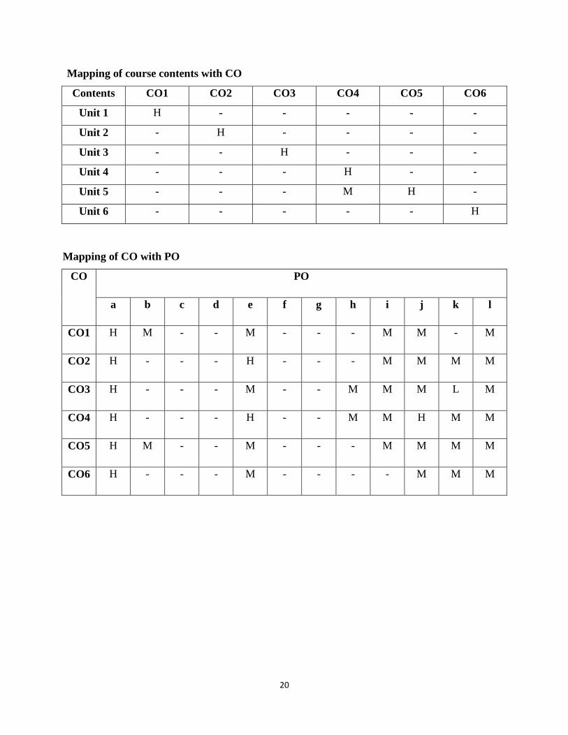
Mapping of course contents with CO
Contents CO1 CO2 CO3 CO4 CO5 CO6
Unit 1 H - - - - -
Unit 2 - H - - - -
Unit 3 - - H - - -
Unit 4 - - - H - -
Unit 5 - - - M H -
Unit 6 - - - - - H
Mapping of CO with PO
CO PO
a b c d e f g h i j k l
CO1 H M - - M - - - M M - M
CO2 H - - - H - - - M M M M
CO3 H - - - M - - M M M L M
CO4 H - - - H - - M M H M M
CO5 H M - - M - - - M M M M
CO6 H - - - M - - - - M M M

21
COURSE NAME: LAB ELECTRONICS DEVICES & CIRCUITS-II
COURSE CODE: EC-14407
Internal Marks: 30 L T P
External Marks: 20 - - 2
NOTE: Do all Experiments. Evaluation of the lab work shall be done as per the approved
Rubric.
Course Outcomes
On successful completion of this course, the students should be able to:
CO1 Analyze effect of different coupling techniques on the performance of transistor amplifier.
CO2 Comprehend frequency response of tuned amplifier.
CO3 Observe the operation of various power amplifiers like Class A, B, AB Push pull and
complementary symmetry and conclude on the basis of their efficiency.
CO4 Observe effect of negative feedback on amplification factor.
CO5 Demonstrate working of various RC and LC oscillators along with frequency of
oscillation.
Syllabus:
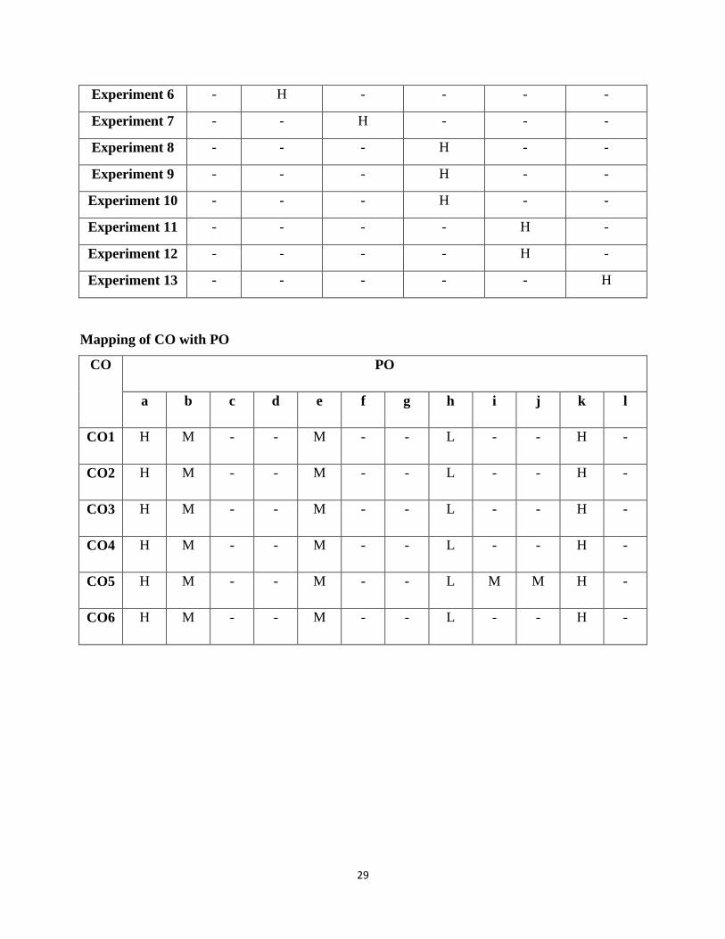
Experiment 1. To demonstrate RC coupling technique for transistor amplifier.
Experiment 2. To demonstrate Transformer coupling technique for transistor amplifier.
Experiment 3. To demonstrate direct coupling technique for transistor amplifier.
Experiment 4. To plot frequency response of a tuned amplifier.
Experiment 5. To observe the operation of Class A amplifier direct coupled and
Transformer coupled with resistive load and calculate efficiency.
Experiment 6. To plot the characteristics of Class A push pull amplifier and calculate
efficiency.
Experiment 7. To observe crossover distortion in Class B push pull amplifier and
calculate efficiency.
Experiment 8. To plot the characteristics of Class AB push pull amplifier and calculate
efficiency.
Experiment 9. To plot the characteristics of complementary symmetry amplifier.

22
Experiment 10. To analyze the effect of negative feedback on amplifier gain.
Experiment 11. To observe the response of RC phase shift oscillator and determine
frequency of oscillation.
Experiment 12. To observe the response of Hartley oscillator and determine frequency of
oscillation.
Experiment 13. To observe the response of Colpitts oscillator and determine frequency of
oscillation.
Experiment 14. To observe the response of Wien Bridge oscillator and determine
frequency of oscillation.
Reference Books and Other Resources:
Lab manuals available in lab.
Mapping of course contents with CO
Contents CO1 CO2 CO3 CO4 CO5
Experiment 1 H - - - -
Experiment 2 H - - - -
Experiment 3 H - - - -
Experiment 4 - H - - -
Experiment 5 - - H - -
Experiment 6 - - H - -
Experiment 7 - - H - -
Experiment 8 - - H - -
Experiment 9 - - H - -
Experiment 10 - - - H -
Experiment 11 - - - - H
23
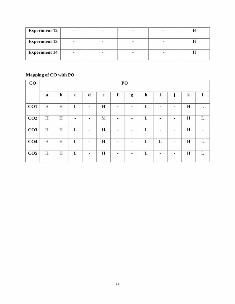
Mapping of CO with PO
CO PO
a b c d e f g h i j k l
CO1 H H L - H - - L - - H L
CO2 H H - - M - - L - - H L
CO3 H H L - H - - L - - H -
CO4 H H L - H - - L L - H L
CO5 H H L - H - - L - - H L
Experiment 12 - - - - H
Experiment 13 - - - - H
Experiment 14 - - - - H

24
COURSE NAME: LAB DIGITAL ELECTRONICS
COURSE CODE: EC-14408
Internal Marks: 30 L T P
External Marks: 20 - - 2
NOTE: Do all Experiments. Evaluation of the lab work shall be done as per the approved
Rubric.
Course Outcomes
On successful completion of this course, the students should be able to:
CO1 Verify the operation of basic and universal gates.
CO2 Design and verify the standard combinational circuits.
CO3 Verify the operation of different types of Flip-Flops.
CO4 Verify the working of shift registers.
CO5 Design counters using Flip-Flops for given count sequence.
Syllabus:
Experiment 1. To verify the truth-tables of OR, AND, NOT, XOR, NAND and NOR
logic gates.
Experiment 2. To realize the OR, AND, NOT and XOR functions using universal gates.
Experiment 3. To realize the Half Adder and Full Adder circuits using logic gates.
Experiment 4. To realize the Half Subtractor and Full Subtractor using logic gates.
Experiment 5. To design 4-Bit Binary-to-Gray Code Converter using logic gates.
Experiment 6. To verify the truth-table of 16:1 Multiplexer and 1:16 Demultiplexer.
Experiment 7. To design and test S-R flip-flop using NAND/NOR gates.
Experiment 8. To verify the truth-tables of J-K, D, and T flip-flops.
Experiment 9. To realize SIPO, SISO, PIPO, and PISO shift register circuits using D flip-
flops.
Experiment 10. To design MOD-10 synchronous up-counter using D flip-flops.
Experiment 11. To operate the counters (using ICs 7490/7493/74192) and verify the
frequency division at each stage. With a low frequency clock (say 1 Hz)
display the count on LEDs.
25
Experiment 12. To study shift-register operations using IC 7495 chip.
Experiment 13. To verify the truth table of decoder driver 7447/7448 and operate a 7-
segment LED/LCD display.
Reference Books and Other Resources:
Lab manuals available in lab.
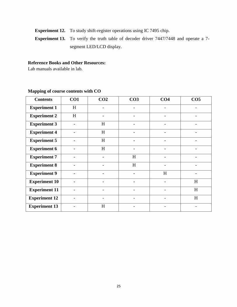
Mapping of course contents with CO
Contents CO1 CO2 CO3 CO4 CO5
Experiment 1 H - - - -
Experiment 2 H - - - -
Experiment 3 - H - - -
Experiment 4 - H - - -
Experiment 5 - H - - -
Experiment 6 - H - - -
Experiment 7 - - H - -
Experiment 8 - - H - -
Experiment 9 - - - H -
Experiment 10 - - - - H
Experiment 11 - - - - H
Experiment 12 - - - - H
Experiment 13 - H - - -
26
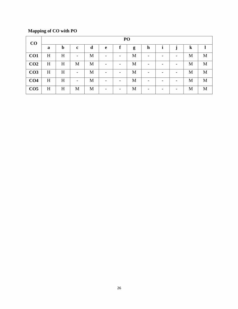
Mapping of CO with PO
CO PO
a b c d e f g h i j k l
CO1 H H - M - - M - - - M M
CO2 H H M M - - M - - - M M
CO3 H H - M - - M - - - M M
CO4 H H - M - - M - - - M M
CO5 H H M M - - M - - - M M

27
COURSE NAME: LAB SIGNALS & SYSTEMS
COURSE CODE: EC-14409
Internal Marks: 30 L T P
External Marks: 20 - - 2
NOTE: Do all Experiments. Evaluation of the lab work shall be done as per the approved
Rubric.
Course Outcomes
On successful completion of this course, the students should be able to:
CO1 Comprehend applications of MATLAB and perform basic mathematical operations on
signals.
CO2 Generate plots of elementary signals in continuous and discrete domain through the use of
M-files.
CO3 Perform operations on signals like shifting, scaling, folding etc.
CO4 Compute Fourier and inverse Fourier Transform of any signal and calculate correlation
and convolution of signals.
CO5 Create random sequences for various distributions and plot its probability density
function.
CO6 Calculate the behavior of LTI system for given input.
Syllabus:
Experiment 1. Introduction to MATLAB and computation of basic mathematical
quantities.
Experiment 2. To create arrays and perform arithmetic and trigonometric operations on
them.
Experiment 3. To generate 2D and 3D plots.
Experiment 4. To create script and function files.
Experiment 5. To develop a program to generate unit step and unit impulse signal in
continuous and discrete domain.
Experiment 6. To develop a program to plot exponential and ramp signal in continuous
and discrete domain.
28
Experiment 7. To develop a program module to perform operations on continuous-time
signals like addition, multiplication, shifting, folding and scaling.
Experiment 8. To compute Fourier transform and inverse Fourier Transform of the given
function.
Experiment 9. To develop a program to compute correlation between continuous-time
signals.
Experiment 10. To develop a program to perform continuous-time convolution.
Experiment 11. To generate random sequences for the following distribution and calculate
mean and variance:
Rayleigh Distribution
Uniform distribution
Gaussian distribution.
Experiment 12. To plot probability density function for Rayleigh, Uniform and Gaussian
Distributed random variables.
Experiment 13. To develop a program for finding response of the LTI system described by
given differential equation.
Suggested Readings/ Books:
1. R. Pratap, “Getting Started with MATLAB: A Quick Introduction for Scientists and
Engineers”, Oxford University Press, 2010.
2. Luis F. Chaparro, “Signals and Systems using MATLAB”, Elsevier, 2nd
Edition, 2015.
3. Lab manuals available in lab.
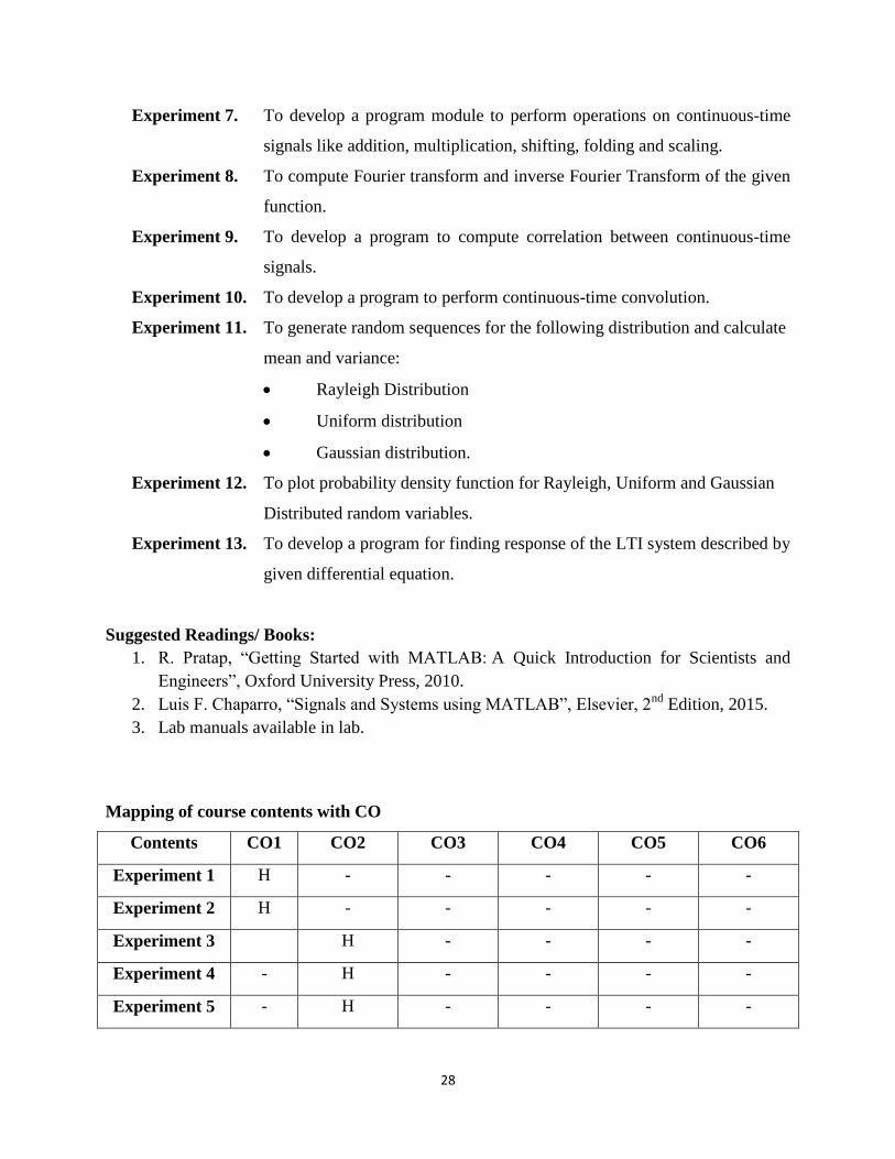
Mapping of course contents with CO
Contents CO1 CO2 CO3 CO4 CO5 CO6
Experiment 1 H - - - - -
Experiment 2 H - - - - -
Experiment 3 H - - - -
Experiment 4 - H - - - -
Experiment 5 - H - - - -
29
Experiment 6 - H - - - -
Experiment 7 - - H - - -
Experiment 8 - - - H - -
Experiment 9 - - - H - -
Experiment 10 - - - H - -
Experiment 11 - - - - H -
Experiment 12 - - - - H -
Experiment 13 - - - - - H
Mapping of CO with PO
CO PO
a b c d e f g h i j k l
CO1 H M - - M - - L - - H -
CO2 H M - - M - - L - - H -
CO3 H M - - M - - L - - H -
CO4 H M - - M - - L - - H -
CO5 H M - - M - - L M M H -
CO6 H M - - M - - L - - H -
30
5TH
SEMESTER

31
COURSE NAME: ANTENNA AND WAVE PROPAGATION COURSE CODE: EC-14501
Internal Marks: 40 L T P
External Marks: 60 3 1 -
Numerical & Design Problems Content: 20%-30%
Note: The question paper shall consist of eight questions of twenty (20) marks each, out of
which five questions are required to be attempted by the candidate.
Course Outcomes:
The students should be able to:
CO1 Comprehend the fundamental principles and parameters of antenna theory.
CO2 Comprehend basic and practical configurations, such as linear dipoles; arrays, aperture
patches etc.
CO3 Design antenna arrays.
CO4 Understand various types of wave propagation.
Syllabus:
Unit 1. Introduction
Types of Antennas, Radiation Mechanism in single, two wire and dipole, Current Distribution on
a Thin Wire Antenna.
Unit 2. Fundamental parameters of antennas
Radiation Pattern, Radiation Power Density, Radiation intensity, Directivity, Gain, Antenna
efficiency, Bandwidth, Polarisation, Antenna Input Impedance, Antenna Vector Effective length
and equivalent areas, Maximum Directivity and Maximum Effective Area, Return Loss, Friis
Transmission equation and Radar range Equation, Effective aperture, Antenna Temperature.
Unit 3. Linear Wire Antennas
Retarded potential, Infinitesimal dipole, Current distribution of short dipole and half wave
dipole, Far-field, Radiating near-field and reactive near-field region, Monopole and Half wave
dipole.
32
Unit 4. Antenna Arrays
Array of two point sources, Array factor, n-element linear array with uniform amplitude and
spacing, Analysis of Broadside array, Ordinary end-fire array, Hansen-woodyard end fire array,
n-element linear array with non-uniform spacing, Analysis of Binomial and Dolph-
Tschebyscheff array, Scanning Array, Superdirective array.
Unit 5. Aperture and Microstrip Antennas
Field Equivalence principle, Rectangular and circular aperture antennas, Horn antenna, Babinet’s
Principle, Slot Antenna, Reflector antenna, microstrip antennas, rectangular patch, circular patch,
arrays and feed networks for microstrip antennas, introduction to antenna design softwares.
Unit 6. Wave Propagation
Free space equation, Reflection from earth’s surface, Surface and Space wave propagation,
Range of space wave propagation, Effective earth’s radius, Duct propagation, Troposphere
propagation. Structure of ionosphere, propagation of radio waves through ionosphere, Critical
frequency, Maximum usable frequency, Optimum working frequency, lowest usable high
frequency, virtual height, Skip Distance, Effect of earth’s magnetic field.
Text Books:
1. Balanis C.A, “Antenna Theory”, John Wiley & sons, 2005.
2. Krauss J.D, “Antenna Theory”, McGraw Hill.
Reference Books:
1. Jordan E. C, “Electromagnetics and radiating systems”, PHI, 2007.
2. Collins R. E., “Antenna and radio wave propagation”, McGraw Hill.
3. Kennedy, G. “ Electronic Communication Systems”, TMH, Fourth Edition.
33
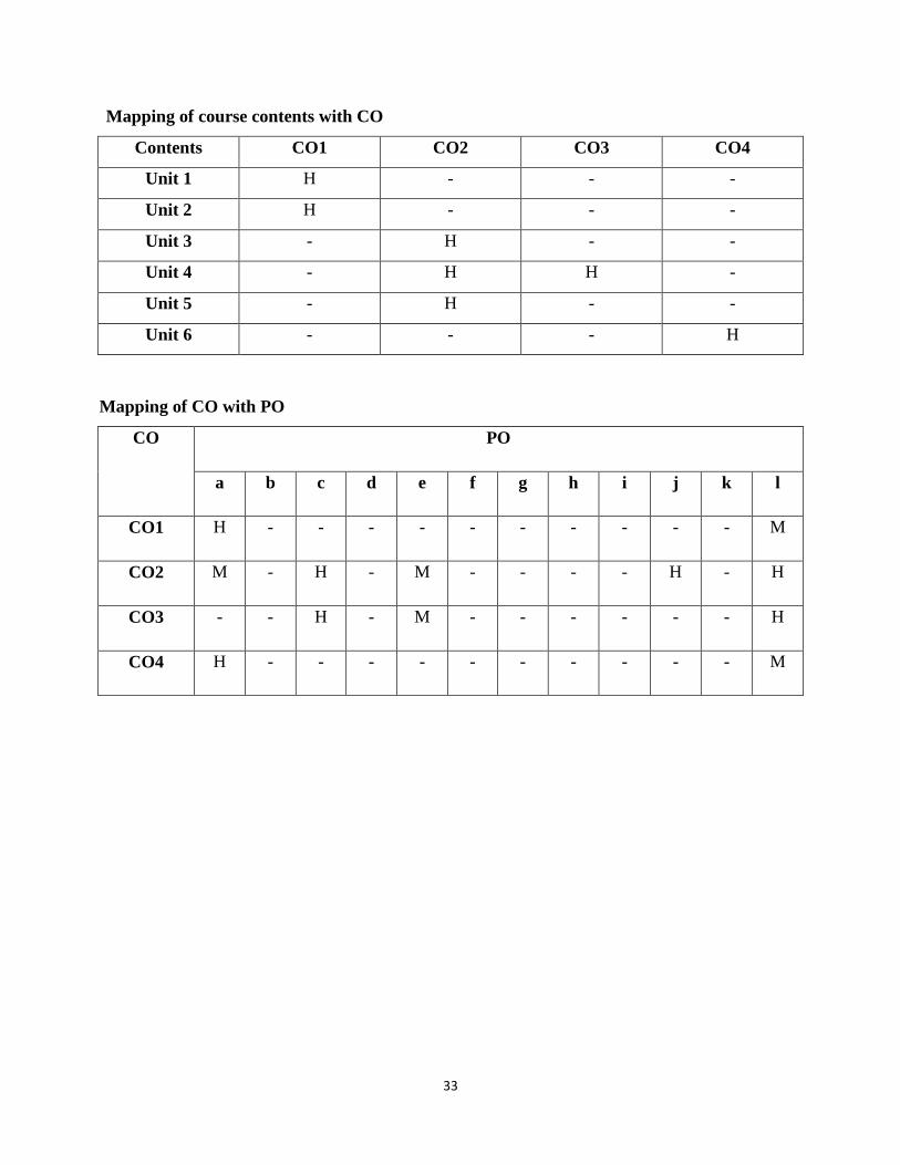
Mapping of course contents with CO
Contents CO1 CO2 CO3 CO4
Unit 1 H - - -
Unit 2 H - - -
Unit 3 - H - -
Unit 4 - H H -
Unit 5 - H - -
Unit 6 - - - H
Mapping of CO with PO
CO PO
a b c d e f g h i j k l
CO1 H - - - - - - - - - - M
CO2 M - H - M - - - - H - H
CO3 - - H - M - - - - - - H
CO4 H - - - - - - - - - - M
34
COURSE NAME: ANALOG COMMUNICATION SYSTEMS
COURSE CODE: EC-14502
Internal Marks: 40 L T P
External Marks: 60 3 1 -
Numerical & Design Problems Content: 20% -30%
Note: The Question paper shall have three sections:
Section A shall consist of one question with 10 sub-questions of two (02) marks each. Section B
shall consist of five questions of five (05) marks each, out of which four questions are required to
be attempted by the candidate. Section C shall consist of three questions of ten (10) marks each,
out of which two questions are required to be attempted by the candidate. Any question of
Section C may be sub–divided (if required) into two parts of five (05) marks each.
Course Outcomes
On successful completion of this course, the students should be able to:
CO1 Describe a Communication system & explain the basic theory of Modulation.
CO2 Perform the Mathematical analysis of different analog modulation techniques
CO3 Describe the various methods of generation & detection of AM, FM and SSB modulation
schemes
CO4 Compare the different modulation schemes.
CO5 Discuss the Super heterodyne receiver in detail.
CO6 Explain the concept of Sampling and Pulse Modulation techniques
Syllabus:
Unit 1. Analog Modulation Techniques: Introduction, Elements of a Communication System,
Modulation & Demodulation, Need of modulation, Types of analog modulations, theory of
amplitude modulation, AM power calculations, AM current calculations, AM modulation with a
complex wave, theory of frequency modulation, mathematical analysis of FM, spectra of FM
signals, Narrowband FM, Wideband FM, theory of phase modulation, phase modulation
obtained from frequency modulation, Comparison of AM & FM, Comparison of PM & FM.

35
Unit 2. AM Transmission and Reception: Introduction, Low level and high level modulation,
Basic principle of AM generation, AM generation using Square law modulation, Collector
modulation of Class C transistor amplifiers, Balanced modulator and Ring modulator
(Suppressed carrier AM generation), Product modulator; Receiver parameters: Selectivity,
Sensitivity, Fidelity, Noise figure, Tuned radio frequency receiver, Super heterodyne receiver,
Basic elements of AM super heterodyne receiver: RF amplifier circuit, Mixer/ Converter circuits:
Self- excited mixer, Separately excited mixer, Diode mixer & Balanced diode mixer, Local
oscillator Tracking, Choice of IF frequency, IF amplifier circuit, Image frequency & its rejection,
AM detection: Envelope or diode detector, Principle of Simple AGC, AM detector with AGC,
Distortion in diode detectors, Double hetero-dyne AM receivers, AM receiver using Phase
locked loop.
Unit 3. FM Transmission and Reception: FM allocation standards, generation of FM by direct
methods: Varactor diode modulator, Reactance modulator, Phase locked loop direct FM
transmitter; Indirect generation of FM: Armstrong method; Frequency stabilized reactance FM
transmitter; Frequency demodulators: Balanced Slope detector, Foster Seeley discriminator,
Ratio detector; FM detection using PLL, Pre-emphasis & De-emphasis, Limiter circuit, FM
capture effect, FM Receiver.
Unit 4. SSB Transmission and Reception: Introduction, Advantages of SSB transmission,
Generation of SSB: Filter method, Phase shift method, Third Method, Pilot carrier SSB systems,
Independent Sideband (ISB) Transmitter, Vestigial Sideband (VSB) transmission. SSB Product
demodulator, Balanced modulator as SSB demodulator, Pilot carrier SSB Receiver, ISB
Receiver.
Unit 5. Pulse Modulation Transmission and Reception: Introduction, Sampling theorm, Pulse
Amplitude Modulation(PAM), Natural PAM, Frequency spectra for PAM, Flat-top PAM, PAM
Time Multiplexing, PAM modulator, PAM demodulator, Pulse Time Modulation:- Pulse Width
Modulation (PWM) & demodulation, Pulse Position Modulation & demodulation.

36
Text Books:
1. G. Kennedy & B. Davis, Electronic Communication Systems, McGraw-Hill Electrical
Engineering Series, 4th
Edition, Glencoe Publishers,1993.
2. Wayne Tomasi, Electronic Communications Systems-Fundamental through Advanced,
5th
Edition, Pearson Education,2001.
Reference Books/ Study Material:
1. Dennis Roddy & John Coolen, Electronic Communications, 4th
edition, Pearson
Education, 2009.
2. H. Taub & Donald L.Schilling, Principles of Communication Systems ,3rd
Edition,
Tata McGraw Hill Education, 2008.
3. L. W. Couch, Digital and Analog Communication Systems, 8th
Edition, Pearson
Education 2012.
4. K. Sam. Shanmugam, Digital and Analog Communication Systems, Student Edition,
Wiley India Publications, 2006.
Mapping of course contents with CO
Contents CO1 CO2 CO3 CO4 CO5 CO6
Unit 1 H H - H - -
Unit 2 - L H - H -
Unit 3 - - H - L -
Unit 4 - - H H - -
Unit 5 - - - - - H
37
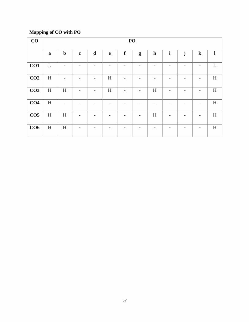
Mapping of CO with PO
CO PO
a b c d e f g h i j k l
CO1 L - - - - - - - - - - L
CO2 H - - - H - - - - - - H
CO3 H H - - H - - H - - - H
CO4 H - - - - - - - - - - H
CO5 H H - - - - - H - - - H
CO6 H H - - - - - - - - - H

38
COURSE NAME: DIGITAL SIGNAL PROCESSING
COURSE CODE: EC-14503
Internal Marks: 40 L T P
External Marks: 60 3 1 -
Numerical & Design Problems Content: 50%-60%
Note: The Question paper shall have three sections:
Section A shall consist of one question with 10 sub-questions of two (02) marks each. Section B
shall consist of five questions of five (05) marks each, out of which four questions are required to
be attempted by the candidate. Section C shall consist of three questions of ten (10) marks each,
out of which two questions are required to be attempted by the candidate. Any question of
Section C may be sub–divided (if required) into two parts of five (05) marks each.
Course Outcomes
On successful completion of this course, the students should be able to:
CO1 Discuss the concept of discrete time signals and various manipulations on them.
CO2 Analyze the discrete time systems using z-transform and discrete Fourier transform.
CO3 Realize discrete time systems using various forms of structures.
CO4 Design digital filters using the appropriate method depending upon the specific
requirement.
CO5 Analyze the effects of finite word-length on filter performance.
CO6 Describe the architecture & characteristics of digital signal processors.
Syllabus:
Unit 1. Introduction
Basic elements of a DSP system, Advantages and disadvantages of DSP over analog processing,
Applications of digital signal processing.
Unit 2. Discrete-Time Signal and Systems
Elementary discrete-time signals, Classification of discrete-time signals, Manipulation of
discrete-time signals, Input-Output description of discrete-time systems, Block diagram
representation of discrete-time systems, Classification of discrete-time systems, Interconnection

39
of discrete-time systems, Analysis of Linear Time-invariant (LTI) systems using Convolution
Sum method, Causal LTI systems, Stability of LTI systems, Analysis of LTI system using
Difference equation, Cross-correlation and auto-correlation of Discrete-time signals.
Unit 3. z-Transforms
Direct z-transforms and importance of ROC, Properties of z-transform, Rational z-transforms,
System function of LTI Systems, Inverse z-transform methods, One sided z-transform, Analysis
of LTI systems in z-domain.
Unit 4. Discrete Fourier Transform (DFT)
Frequency domain sampling and reconstruction of discrete time signal, DFT, DFT as linear
transformation, Relationship of DFT to other Transforms, Properties of DFT, Circular
Convolution and DFT, Use of DFT in Linear Filtering, Fast Fourier Transform (FFT)
Algorithms, Radix-2 Decimation-in-time FFT Algorithm, Radix-2 decimation-in-frequency FFT
algorithm.
Unit 5. Implementation of Discrete-Time System
Structures for Realization of discrete-time systems, Structures for FIR systems: Direct form,
Cascade form, and Lattice form; Structures for IIR Systems: Direct Form, Transposed Form,
Cascade Form, Parallel Form and Lattice Form.
Unit 6. Design of Digital Filters
Types of digital filters, Steps of filter design, Linear-phase response filter, Design of FIR filter
using window method, Design of IIR Filter by Impulse Invariance, Bilinear Transformation and
Matched z-Transform Technique, Analog and Digital Domain Frequency Transformation,
Representation of Numbers and Finite Word Length Effects.
Unit 7. Digital Signal Processors
Introduction, Computer architecture for signal processing, Difference between general and
special-purpose digital signal processors, Selecting digital signal processors, Overview of ADSP
2100 and TMS320C50 processors.
40
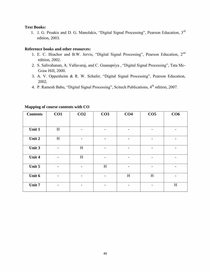
Text Books:
1. J. G. Proakis and D. G. Manolakis, “Digital Signal Processing”, Pearson Education, 3rd
edition, 2003.
Reference books and other resources:
1. E. C. Ifeachor and B.W. Jervis, “Digital Signal Processing”, Pearson Education, 2nd
edition, 2002.
2. S. Salivahanan, A. Vallavaraj, and C. Gnanapriya , “Digital Signal Processing”, Tata Mc-
Graw Hill, 2000.
3. A. V. Oppenheim & R. W. Schafer, “Digital Signal Processing”, Pearson Education,
2002.
4. P. Ramesh Babu, “Digital Signal Processing”, Scitech Publications, 4th
edition, 2007.
Mapping of course contents with CO
Contents
CO1 CO2 CO3 CO4 CO5 CO6
Unit 1 H - - - - -
Unit 2 H - - - - -
Unit 3 - H - - - -
Unit 4 - H - - - -
Unit 5 - - H - - -
Unit 6 - - - H H -
Unit 7 - - - - - H

41
Mapping of CO with PO
CO PO
a b c d e f g h i j k L
CO1 M - - - L - - - - - - L
CO2 M - - - L - - - - - - M
CO3 M - M - L - - - - - - H
CO4 M - H - M -- - - - - - L
CO5 M - - - L - - - - - - L
CO6 M - - - - - - - - - - L

42
COURSE NAME: LINEAR INTEGRATED CIRCUITS
COURSE CODE: EC-14504
Internal Marks: 40 L T P
External Marks: 60 3 1 -
Numerical & Design Problems Content: 30%-40%
Note: The Question paper shall have three sections:
Section A shall consist of one question with 10 sub-questions of two (02) marks each. Section B
shall consist of five questions of five (05) marks each, out of which four questions are required to
be attempted by the candidate. Section C shall consist of three questions of ten (10) marks each,
out of which two questions are required to be attempted by the candidate. Any question of
Section C may be sub–divided (if required) into two parts of five (05) marks each.
Course Outcomes
On successful completion of this course, the students should be able to:
CO1 Describe the differential amplifiers with different configurations along with DC and
AC analysis.
CO2 Define and explain the characteristics for an Ideal & Practical operational amplifier
and analyse its performance parameters.
CO3 Describe the applications of op-amp.
CO4 Explain working principle of IC555 Timer and its applications as Multivibrators.
CO5 Discuss working of phase locked loop and compare different types of voltage
regulators.
Syllabus:
Unit 1. Differential and Cascade Amplifiers
Introduction, DifferentialAmplifier, Differential Amplifier Circuit Configuration, Dual Input-
Balanced output Differential Amplifier, Dual Input-Unbalanced output Differential Amplifier,
Single Input-Balanced output Differential Amplifier, Single Input-unbalanced output Differential
Amplifier with their DC and AC analysis, Differential Amplifier with swamping resistors,
Constant current bias, Current Mirror, Cascaded differential Amplifier Stages, Level Translator,
CE-CB configuration.
43
Unit 2. Introduction to Operational Amplifiers
Block diagram of a typical Op-Amp, Schematic symbol, integrated circuits and their types, IC
package types, Pin Identification and temperature range, Interpretation of data sheets, Overview
of typical set of data sheets, Characteristics and performance parameters of an Op-Amp, Ideal
Op-Amp, Equivalent circuit of an Op-Amp, Ideal voltage transfer curve, Open loop
configurations : Differential, Inverting & Non Inverting. Practical Op-Amp: Input offset voltage,
Input bias current, Input offset current, total output offset voltage, Thermal drift, Effect of
variation in power supply voltages on offset voltage, Change in Input offset voltage and Input
offset current with time, Temperature and supply voltage sensitive parameters, Noise, Common
Mode configuration and common mode rejection Ratio.
Unit 3. Applications of Op-Amp
Applications of Op-Amp as: DC and AC amplifiers, Peaking Amp, Summing, Scaling and
Averaging Amplifier, Instrumentation Amplifier, V to I and I to V converter, Log and Antilog
Amp, Integrator, Differentiator. Active filters: First order LP Butterworth filter, Second order LP
Butterworth filter, First order HP Butterworth filter, Second order HP Butterworth filter, Higher
order filters, Band pass filter, Band reject filters, All pass filter, Phase shift oscillator, Wein
bridge oscillator, Quadrature oscillator, Square wave generator, Triangular wave generator,
Sawtooth wave generator, Voltage controlled oscillator, Basic comparator, Zero crossing
detector, Schmitt trigger, window detector, V to F and F to V converters, A to D and D to A
converters, Peak Detector, Sample and Hold Circuit.
Unit 4. Specialized IC Applications
IC 555 Timer: Pin configuration, Block diagram, application of IC 555 as Monostable and
Astable Multivibrator., Phase Lock Loops: Operating principles & applications of IC 565,
Voltage Regulators: Fixed voltage regulators, Adjustable voltage regulators, Switching
Regulators.
Text Book:
1. R. Gayakwad, “Op-Amps & Linear Integrated circuits”, Pearson Prentice Hall, 3rd
Edition, 2006.
44
Reference Books and Other Resources:
1. R. F. Coughlin And F. F. Driscoll, “Operatinal Amplifiers & Linear Integrated circuits”,
Prentice Hall, 5th
edition, 1998.
2. J. M. Fiore, “OP Amps and Linear Integrated Circuits: Concepts and Applications”,
Cengage Learning, 1st edition, 2010.
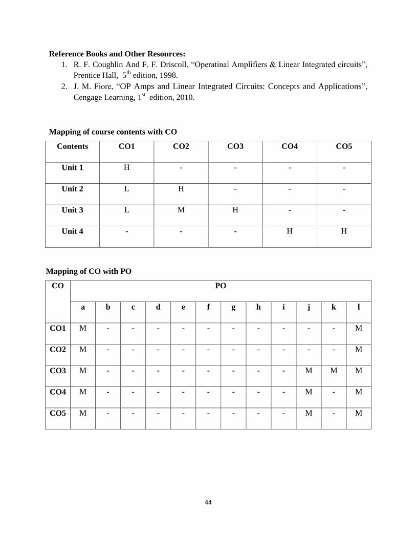
Mapping of course contents with CO
Contents CO1 CO2 CO3 CO4 CO5
Unit 1 H - - - -
Unit 2 L H - - -
Unit 3 L M H - -
Unit 4 - - - H H
Mapping of CO with PO
CO PO
a b c d e f g h i j k l
CO1 M - - - - - - - - - - M
CO2 M - - - - - - - - - - M
CO3 M - - - - - - - - M M M
CO4 M - - - - - - - - M - M
CO5 M - - - - - - - - M - M
45
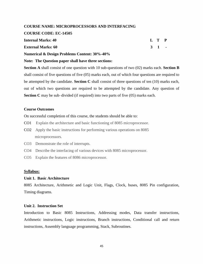
COURSE NAME: MICROPROCESSORS AND INTERFACING
COURSE CODE: EC-14505
Internal Marks: 40 L T P
External Marks: 60 3 1 -
Numerical & Design Problems Content: 30%-40%
Note: The Question paper shall have three sections:
Section A shall consist of one question with 10 sub-questions of two (02) marks each. Section B
shall consist of five questions of five (05) marks each, out of which four questions are required to
be attempted by the candidate. Section C shall consist of three questions of ten (10) marks each,
out of which two questions are required to be attempted by the candidate. Any question of
Section C may be sub–divided (if required) into two parts of five (05) marks each.
Course Outcomes
On successful completion of this course, the students should be able to:
CO1 Explain the architecture and basic functioning of 8085 microprocessor.
CO2 Apply the basic instructions for performing various operations on 8085
microprocessors.
CO3 Demonstrate the role of interrupts.
CO4 Describe the interfacing of various devices with 8085 microprocessor.
CO5 Explain the features of 8086 microprocessor.
Syllabus:
Unit 1. Basic Architecture
8085 Architecture, Arithmetic and Logic Unit, Flags, Clock, buses, 8085 Pin configuration,
Timing diagrams.
Unit 2. Instruction Set
Introduction to Basic 8085 Instructions, Addressing modes, Data transfer instructions,
Arithmetic instructions, Logic instructions, Branch instructions, Conditional call and return
instructions, Assembly language programming, Stack, Subroutines.
46
Unit 3. Interrupts
8085 interrupts, Basic interrupt processing, ISR, RST, RIM, SIM.
Unit 4. Peripheral Devices
8255(PPI), 8279(Keyboard and display controller), 8259(PIC), 8237(DMA), RS-232.
Unit 5. Interfacing
Memory interfacing, Interfacing of Keyboard and Seven Segment LED Display, Microprocessor
Controlled Temperature System(MCTS), Study of Traffic Light System, Stepper Motor
Controller.
Unit 6. 8086 Microprocessors
Features, Architecture, Flags, Segment registers, Directives.
Text Books:
1. Ramesh S. Gaonkar, Microprocessor Architecture, Programming and application with 8085,
5th Edition, Penram International Publishing, New Delhi, 2007.
2. John Uffenbeck, The 80x86 Family, Design, Programming and Interfacing, Third Edition.
Pearson Education, 2002.
Reference books and other resources:
1. A. K. Ray and K. M. Burchandi, Intel Microprocessors Architecture Programming and
Interfacing, McGraw Hill International Edition, 2000
2. M. Rafi Quazzaman, Microprocessors Theory and Applications: Intel and Motorola
prentice Hall of India, Pvt. Ltd., New Delhi, 2003.
3. D. V. Hall, “Microprocessor and Interfacing-Programming and Hardware”, 2nd Ed., Tata
McGraw-Hill Publishing Company Limited, 2008.
4. J. Stewart ,“Microprocessor Systems- Hardware, Software and Programming”, Prentice
Hall International Edition,1990
5. K. L. Short,“Microprocessors and Programmed Logic”, 2nd Ed.,Pearson Education, 2008.

47
Mapping of course contents with CO
Contents CO1 CO2 CO3 CO4 CO5
UNIT 1 H - - - -
UNIT 2 - H L L -
UNIT 3 - - H -
UNIT 4 L L - H -
UNIT 5 - L - H -
UNIT 6 - - - - H
Mapping of CO with PO
CO PO
a b c d e f g h i j k l
CO1 H M - - M - - L M M M M
CO2 H - - - H - - M M M M M
CO3 H - - - M - - M M M L M
CO4 H - - - H - - M M H M M
CO5 H M - - M - - M M M M M

48
COURSE NAME: LAB LINEAR INTEGRATED CIRCUITS
COURSE CODE: EC-14510
Internal Marks: 30 L T P
External Marks: 20 - - 2
NOTE: Do all Experiments. Evaluation of the lab work shall be done as per the approved
Rubric.
Course Outcomes
On successful completion of this course, the students should be able to:
CO1 Implement various differential amplifier configurations.
CO2 Measure frequency response of op-amp and apply op-amp as inverting and non
inverting amplifiers.
CO3 Implement amplifiers, differentiator, integrator and Butterworth filter circuits using
op-amp.
CO4 Apply op-amp as oscillator, wave generators and Schmitt Trigger circuits.
CO5 Design phase locked loop and verify the results on SPICE.
Syllabus:
Experiment 1. To study differential amplifier configurations.
Experiment 2. To study op-amp as inverting and non inverting amplifier.
Experiment 3. To study frequency response of an op-amp.
Experiment 4. To use op-amp as summing, scaling & averaging amplifier.
Experiment 5. To use op-amp as instrumentation amplifier.
Experiment 6. To design differentiator and integrator using op-amp.
Experiment 7. To design low-pass, high-pass and band-pass 1st order Butterworth active
filters using op-amp.
Experiment 8. To design Phase shift oscillator using op-amp.
Experiment 9. To study op-amp as Sawtooth wave generator.
Experiment 10. To study op-amp as Schmitt Trigger.
Experiment 11. To examine the operation of a PLL and to determine the free running
frequency, the capture range and the lock in range of PLL.
49
Experiment 12. Introduction of SPICE software and its use for op-amp circuits.
Experiment 13. Verification of hardware results obtained using SPICE software.
Reference Books and Other Resources:
Lab manuals available in lab.
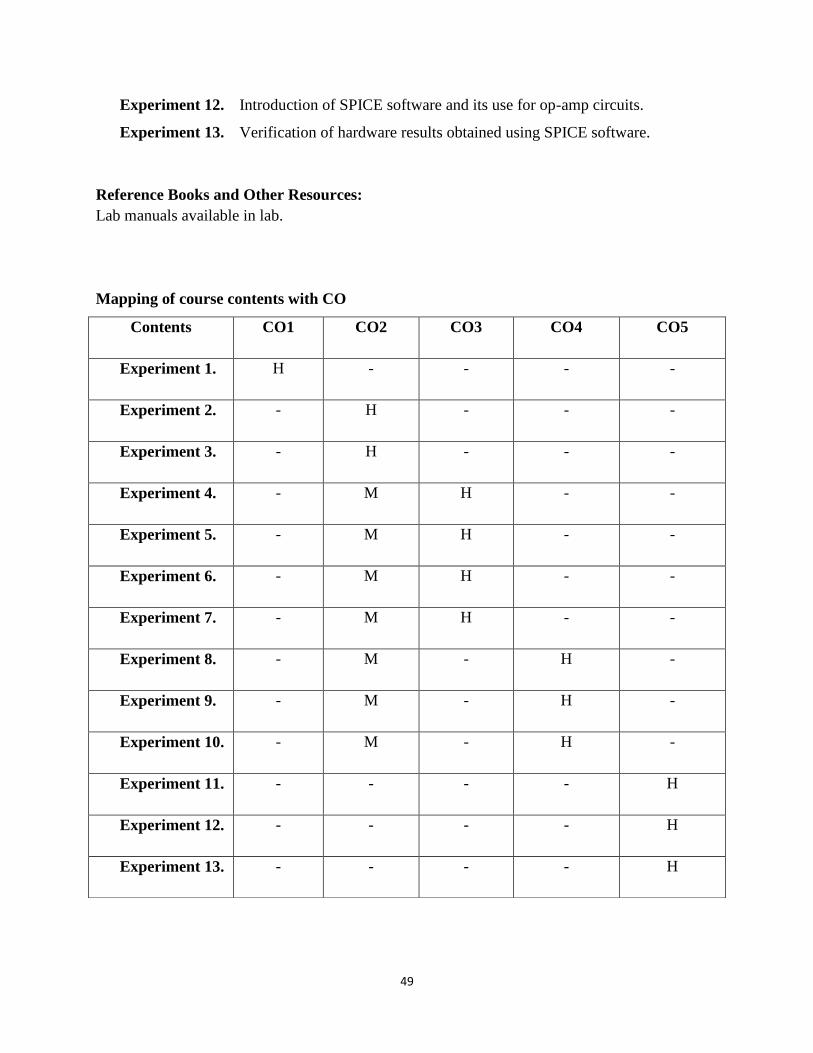
Mapping of course contents with CO
Contents CO1 CO2 CO3 CO4 CO5
Experiment 1. H - - - -
Experiment 2. - H - - -
Experiment 3. - H - - -
Experiment 4. - M H - -
Experiment 5. - M H - -
Experiment 6. - M H - -
Experiment 7. - M H - -
Experiment 8. - M - H -
Experiment 9. - M - H -
Experiment 10. - M - H -
Experiment 11. - - - - H
Experiment 12. - - - - H
Experiment 13. - - - - H

50
Mapping of CO with PO
CO PO
a b c d e f g h i j k l
CO1 H H - M - - M - - - M M
CO2 H H - M - - M - - - M M
CO3 H H - M - - M - - - M M
CO4 H H - M - - M - - - M M
CO5 H H - M - - M - - - M M
51
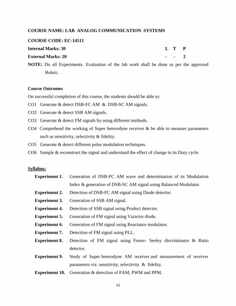
COURSE NAME: LAB ANALOG COMMUNICATION SYSTEMS
COURSE CODE: EC-14511
Internal Marks: 30 L T P
External Marks: 20 - - 2
NOTE: Do all Experiments. Evaluation of the lab work shall be done as per the approved
Rubric.
Course Outcomes
On successful completion of this course, the students should be able to:
CO1 Generate & detect DSB-FC AM & DSB-SC AM signals.
CO2 Generate & detect SSB AM signals.
CO3 Generate & detect FM signals by using different methods.
CO4 Comprehend the working of Super heterodyne receiver & be able to measure parameters
such as sensitivity, selectivity & fidelity.
CO5 Generate & detect different pulse modulation techniques.
CO6 Sample & reconstruct the signal and understand the effect of change in its Duty cycle.
Syllabus:
Experiment 1. Generation of DSB-FC AM wave and determination of its Modulation
Index & generation of DSB-SC AM signal using Balanced Modulator.
Experiment 2. Detection of DSB-FC AM signal using Diode detector.
Experiment 3. Generation of SSB AM signal.
Experiment 4. Detection of SSB signal using Product detector.
Experiment 5. Generation of FM signal using Varactor diode.
Experiment 6. Generation of FM signal using Reactance modulator.
Experiment 7. Detection of FM signal using PLL.
Experiment 8. Detection of FM signal using Foster- Seeley discriminator & Ratio
detector.
Experiment 9. Study of Super heterodyne AM receiver and measurement of receiver
parameters viz. sensitivity, selectivity & fidelity.
Experiment 10. Generation & detection of PAM, PWM and PPM.
52
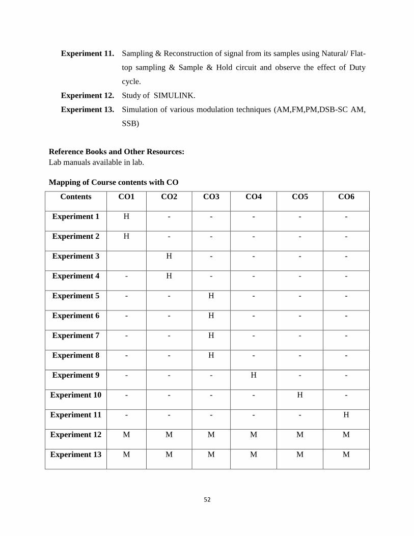
Experiment 11. Sampling & Reconstruction of signal from its samples using Natural/ Flat-
top sampling & Sample & Hold circuit and observe the effect of Duty
cycle.
Experiment 12. Study of SIMULINK.
Experiment 13. Simulation of various modulation techniques (AM,FM,PM,DSB-SC AM,
SSB)
Reference Books and Other Resources:
Lab manuals available in lab.
Mapping of Course contents with CO
Contents CO1 CO2 CO3 CO4 CO5 CO6
Experiment 1 H - - - - -
Experiment 2 H - - - - -
Experiment 3 H - - - -
Experiment 4 - H - - - -
Experiment 5 - - H - - -
Experiment 6 - - H - - -
Experiment 7 - - H - - -
Experiment 8 - - H - - -
Experiment 9 - - - H - -
Experiment 10 - - - - H -
Experiment 11 - - - - - H
Experiment 12 M M M M M M
Experiment 13 M M M M M M

53
Mapping of CO with PO
CO PO
a b c d e f g h i j k l
CO1 H - - - L - - - - - H -
CO2 H - - - L - - - - - H -
CO3 H - - - L - - - - - H -
CO4 H H - - L - - - - - H -
CO5 H - - - L - - - - - H -
CO6 H L - - - - - - - - H -
54
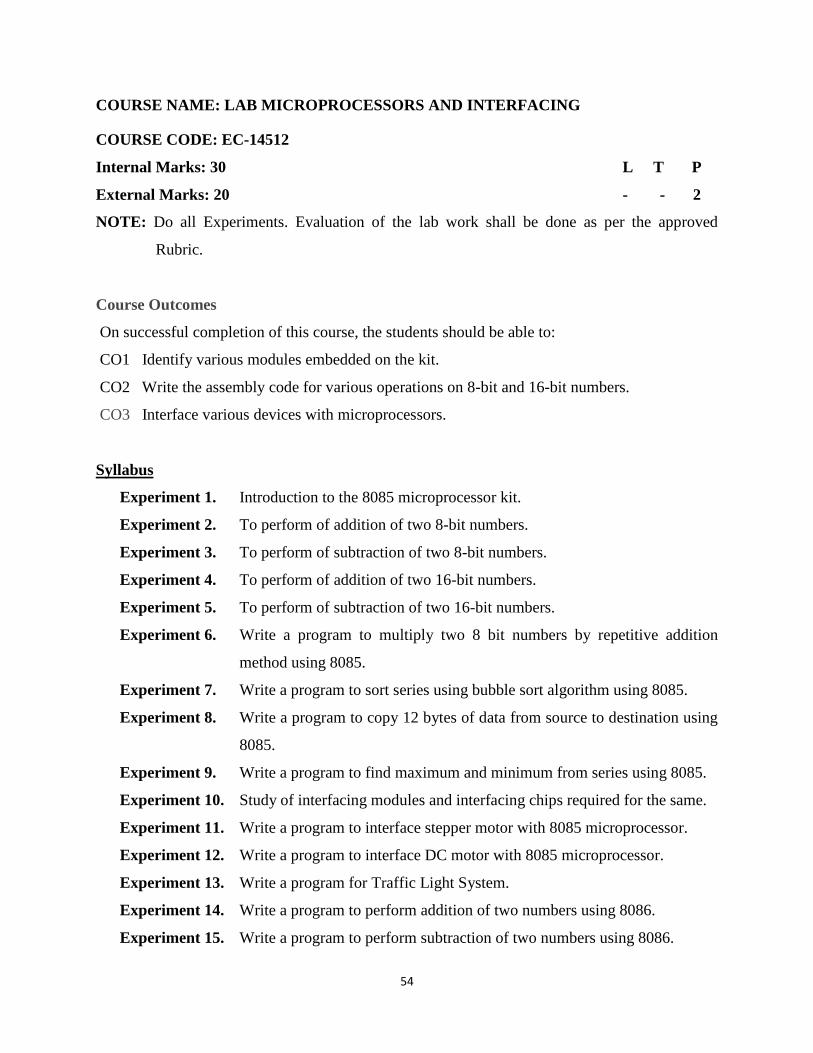
COURSE NAME: LAB MICROPROCESSORS AND INTERFACING
COURSE CODE: EC-14512
Internal Marks: 30 L T P
External Marks: 20 - - 2
NOTE: Do all Experiments. Evaluation of the lab work shall be done as per the approved
Rubric.
Course Outcomes
On successful completion of this course, the students should be able to:
CO1 Identify various modules embedded on the kit.
CO2 Write the assembly code for various operations on 8-bit and 16-bit numbers.
CO3 Interface various devices with microprocessors.
Syllabus
Experiment 1. Introduction to the 8085 microprocessor kit.
Experiment 2. To perform of addition of two 8-bit numbers.
Experiment 3. To perform of subtraction of two 8-bit numbers.
Experiment 4. To perform of addition of two 16-bit numbers.
Experiment 5. To perform of subtraction of two 16-bit numbers.
Experiment 6. Write a program to multiply two 8 bit numbers by repetitive addition
method using 8085.
Experiment 7. Write a program to sort series using bubble sort algorithm using 8085.
Experiment 8. Write a program to copy 12 bytes of data from source to destination using
8085.
Experiment 9. Write a program to find maximum and minimum from series using 8085.
Experiment 10. Study of interfacing modules and interfacing chips required for the same.
Experiment 11. Write a program to interface stepper motor with 8085 microprocessor.
Experiment 12. Write a program to interface DC motor with 8085 microprocessor.
Experiment 13. Write a program for Traffic Light System.
Experiment 14. Write a program to perform addition of two numbers using 8086.
Experiment 15. Write a program to perform subtraction of two numbers using 8086.

55
Experiment 16. Case Study: Microprocessor based projects.
Reference Books and Other Resources:
Lab manuals available in lab.
Mapping of Course contents with CO
Contents CO1 CO2 CO3
Experiment 1 H - -
Experiment 2 - H -
Experiment 3 - H -
Experiment 4 - H -
Experiment 5 - H -
Experiment 6 - H -
Experiment 7 - H -
Experiment 8 - H -
Experiment 9 - H -
Experiment 10 H -
Experiment 11 - - H
Experiment 12
- - H
Experiment 13 - - H
Experiment 14 - H -
Experiment 15 - H -
Experiment 16 - M H
56
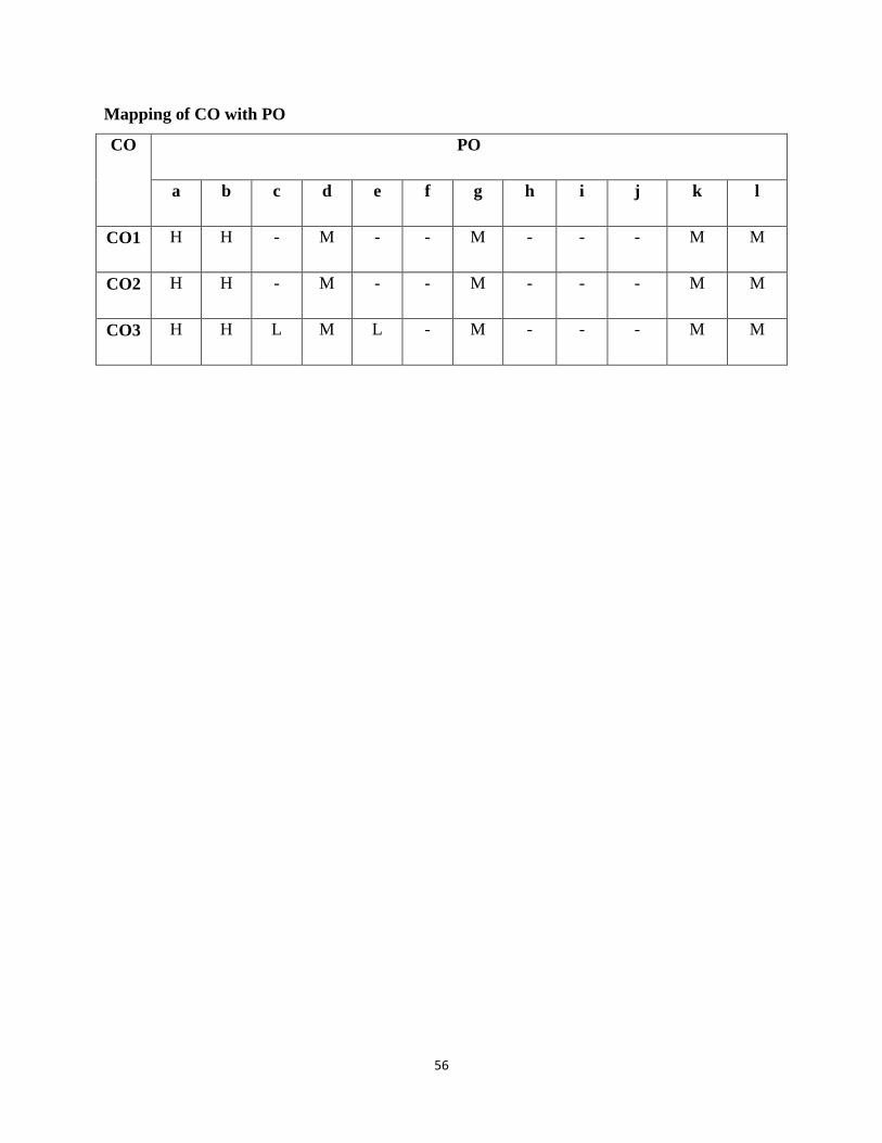
Mapping of CO with PO
CO PO
a b c d e f g h i j k l
CO1 H H - M - - M - - - M M
CO2 H H - M - - M - - - M M
CO3 H H L M L - M - - - M M

57
COURSE NAME: LAB DIGITAL SIGNAL PROCESSING
COURSE CODE: EC-14513
Internal Marks: 30 L T P
External Marks: 20 - - 2
NOTE: Do all Experiments. Evaluation of the lab work shall be done as per the approved
Rubric.
Course Outcomes
On successful completion of this course, the students should be able to:
CO1 Implement various elementary discrete time functions.
CO2 Perform various operations on the discrete time signals.
CO3 Calculate convolution using different transforms.
CO4 Calculate magnitude and phase response of LTI systems.
CO5 Design IIR filters using different methods.
CO6 Design FIR filters using different methods.
Syllabus:
Experiment 1. To develop elementary signal function modules (m-files) for unit sample,
unit step, exponential and unit ramp sequences.
Experiment 2. To develop a program module to perform basic operations on sequences
i.e. addition, multiplication, shifting, folding and scaling.
Experiment 3. To develop a program to find linear convolution and correlation of two
discrete time sequences.
Experiment 4. To develop a program to find linear convolution using z-transforms.
Experiment 5. To develop program for computing inverse z- Transform.
Experiment 6. To develop a program module to perform DFT and IDFT operation on
discrete time sequences.
Experiment 7. To develop a program to find circular convolution of two sequences using
DFT and IDFT method.
58
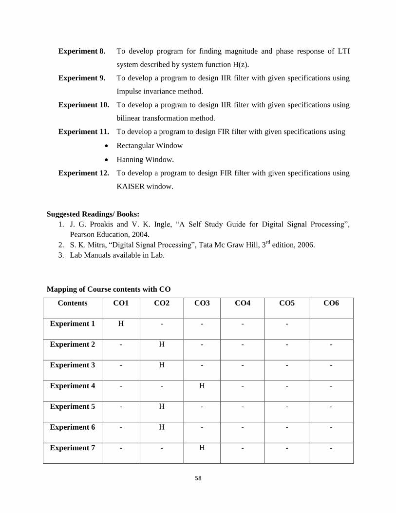
Experiment 8. To develop program for finding magnitude and phase response of LTI
system described by system function H(z).
Experiment 9. To develop a program to design IIR filter with given specifications using
Impulse invariance method.
Experiment 10. To develop a program to design IIR filter with given specifications using
bilinear transformation method.
Experiment 11. To develop a program to design FIR filter with given specifications using
Rectangular Window
Hanning Window.
Experiment 12. To develop a program to design FIR filter with given specifications using
KAISER window.
Suggested Readings/ Books:
1. J. G. Proakis and V. K. Ingle, “A Self Study Guide for Digital Signal Processing”,
Pearson Education, 2004.
2. S. K. Mitra, “Digital Signal Processing”, Tata Mc Graw Hill, 3rd
edition, 2006.
3. Lab Manuals available in Lab.
Mapping of Course contents with CO
Contents CO1 CO2 CO3 CO4 CO5 CO6
Experiment 1 H - - - -
Experiment 2 - H - - - -
Experiment 3 - H - - - -
Experiment 4 - - H - - -
Experiment 5 - H - - - -
Experiment 6 - H - - - -
Experiment 7 - - H - - -

59
Experiment 8 - - - H - -
Experiment 9 - - - - H -
Experiment 10 - - - - H -
Experiment 11 - - - - - H
Experiment 12
- - - - - H
Mapping of CO with PO
CO PO
a b c d e f g h i j k l
CO1 H H - M - - M - - - M M
CO2 H H - M - - M - - - M M
CO3 H H - M - - M - - - M M
CO4 H H - M - - M - - - M M
CO5 H H H M H - M - - - M M
CO6 H H H M H - M - - - M M

60
COURSE NAME: INTELLECTUAL PROPERTY RIGHTS
COURSE CODE: DEEC-14506
Internal Marks: 40 L T P
External Marks: 60 3 1 -
Numerical & Design Problems Content: 0%
Note: The Question paper shall have three sections:
Section A shall consist of one question with 10 sub-questions of two (02) marks each. Section B
shall consist of five questions of five (05) marks each, out of which four questions are required to
be attempted by the candidate. Section C shall consist of three questions of ten (10) marks each,
out of which two questions are required to be attempted by the candidate. Any question of
Section C may be sub–divided (if required) into two parts of five (05) marks each.
Course Outcomes
On successful completion of this course, the students should be able to:
CO1 Describe and classify the different intellectual property Rights.
CO2 Explain the basic concepts of patenting systems and applications.
CO3 Analyze the issue related to protection of copyrights.
CO4 Analyze the issue related to protection of design rights.
CO5 Explain the basic function and selection of trademarks.
Syllabus:
Unit 1. Introduction to Intellectual Property
Introduction, Classification of intellectual property rights, International treaties & conventions,
Acts on intellectual property rights, Domain name disputes and resolution, Cyber Crime offences
and contraventions.
Unit 2. Patent System
Introduction & objective of the patent system, Patent on genetic resources, patents on chemicals,
Designs, patent based on software, Business methods, Internet patent, Obtaining the patent,
Exclusive rights and obligations of a Patentee, Transfer of patent rights, Infringement of a patent.
61
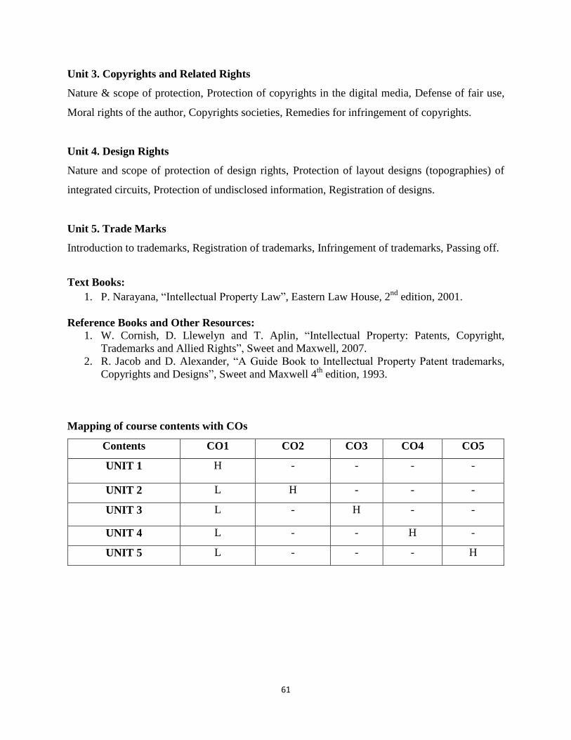
Unit 3. Copyrights and Related Rights
Nature & scope of protection, Protection of copyrights in the digital media, Defense of fair use,
Moral rights of the author, Copyrights societies, Remedies for infringement of copyrights.
Unit 4. Design Rights
Nature and scope of protection of design rights, Protection of layout designs (topographies) of
integrated circuits, Protection of undisclosed information, Registration of designs.
Unit 5. Trade Marks
Introduction to trademarks, Registration of trademarks, Infringement of trademarks, Passing off.
Text Books:
1. P. Narayana, “Intellectual Property Law”, Eastern Law House, 2nd
edition, 2001.
Reference Books and Other Resources:
1. W. Cornish, D. Llewelyn and T. Aplin, “Intellectual Property: Patents, Copyright,
Trademarks and Allied Rights”, Sweet and Maxwell, 2007.
2. R. Jacob and D. Alexander, “A Guide Book to Intellectual Property Patent trademarks,
Copyrights and Designs”, Sweet and Maxwell 4th
edition, 1993.
Mapping of course contents with COs
Contents CO1 CO2 CO3 CO4 CO5
UNIT 1 H - - - -
UNIT 2 L H - - -
UNIT 3 L - H - -
UNIT 4 L - - H -
UNIT 5 L - - - H
62
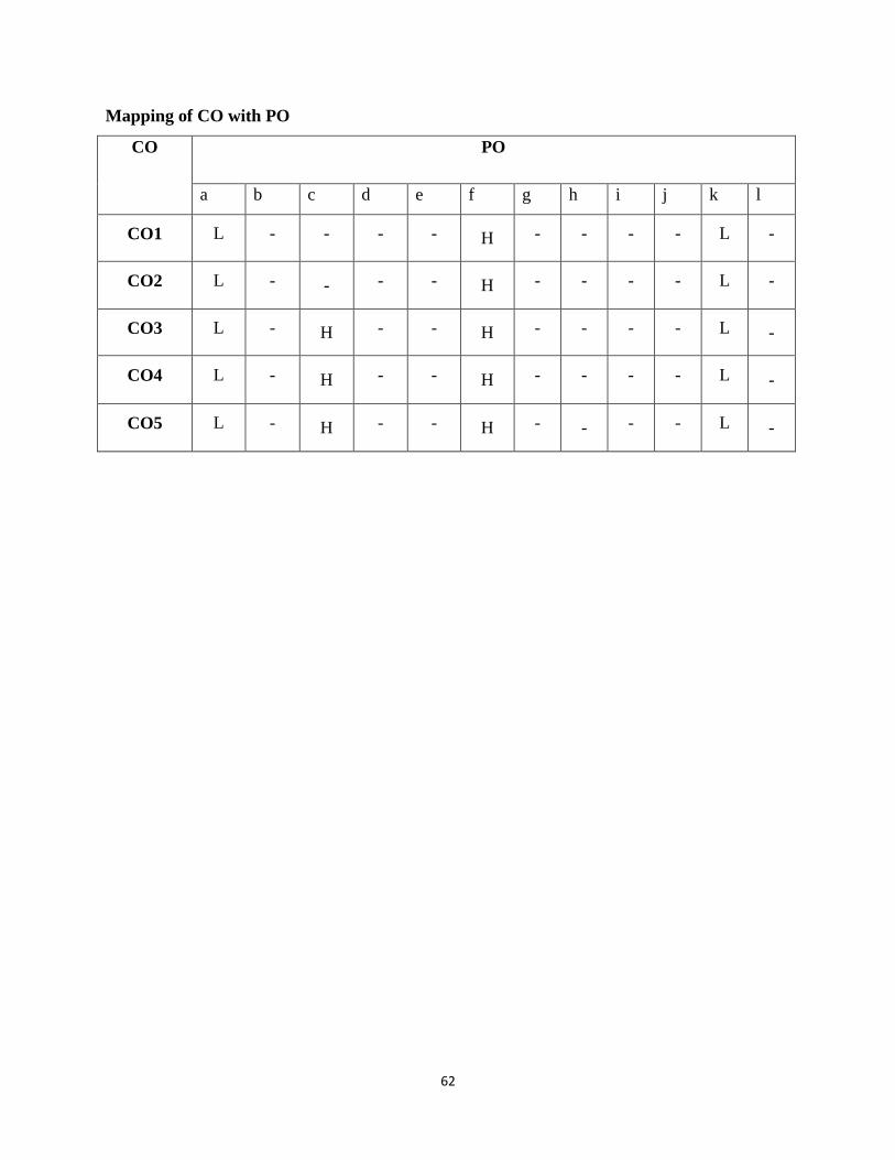
Mapping of CO with PO
CO PO
a b c d e f g h i j k l
CO1 L - - - - H - - - - L -
CO2 L - - - - H - - - - L -
CO3 L - H - - H - - - - L -
CO4 L - H - - H - - - - L -
CO5 L - H - - H - - - - L -