thank you for your interest in rohn products...the information contained in this catalog is intended...
TRANSCRIPT


For over sixty years the ROHN name has been a leader in the telecommunications industry.
The company has used our expertise in structural design and fabrication to expand into
additional markets. ROHN is proud to service the major utility and wind energy companies
in North America. These markets are just two of the latest to join telecom, sports lighting,
broadband, broadcast and the others that have been using ROHN Products to support their
infrastructure projects for six decades.
This year we are proud to o!er the latest version of the ROHN Products Catalog (No. 2). There
have been some major changes to the layout. Some of the changes to Catalog No. 2 are
listed below.
braces).
on page 172.
If you have any questions, comments or suggestions regarding this catalog or any ROHN
products, we are just a phone call away. On the adjacent page we have listed contacts that can
assist you with any questions.
ROHN is committed to providing you the best products in the industry. Our towers are
standing on every continent and in nearly every country around the world. That is because
that tradition this year and in the years to come.
We appreciate your interest in our products and we appreciate your business.
Thank you for your interest in ROHN Products
-The ROHN Team-
The Industry StandardSince 1948
The information contained in this catalog is intended to assist customers in selecting the appropriate ROHN product
for speci"c applications. The information, drawings, etc. are not intended to be substituted for assembly drawings
provided with a ROHN product. Dimensions and weights provided in this catalog are nominal. Refer to our website
www.rohnnet.com for additional information and products.

H O W T O O R D E R I
Phone (309) 566-3000 • Fax (309) 566-3079 • www.rohnnet.com • The Industry Standard© 2011 ROHN PRODUCTS LLC
1
S A L E S T E R R I T O R I E S
ORDERS ORIGINATING IN WESTERN UNITED STATES
ORDERS ORIGINATING IN CENTRAL UNITED STATES & WIND ENERGY
ORDERS ORIGINATING IN EASTERN UNITED STATES
INTERNATIONAL TELECOM & BROADCAST (Outside of U.S.)
Joel Stone309.566.3007
Scott Burdette309.566.3010
Ken Cordrey410.822.8964
Sabet Borairi905.339.4016
UTILITY STRUCTURES
Jeff Arends309.566.3004
For general information or comments, please contact us at (800) 727-ROHN or [email protected]
ORDERS ORIGINATING IN SOUTH EASTERN UNITED STATES
Mike Parrish 863.644.9226
TRANSPORTATION STRUCTURES
Adam Lofgren309.566.3005

I T A B L E O F C O N T E N T S
Phone (309) 566-3000 • Fax (309) 566-3079 • www.rohnnet.com • The Industry Standard© 2011 ROHN PRODUCTS LLC
2
Company History
Industries We Serve
Understanding TIA-222 - Revision G
GUYED TOWERS
G-Series Towers
25G | General Use & Features
Standard Designs (90mph | 110mph | 130mph)
Parts & Accessories
Grounding & Foundations
45G | General Use & Features
Standard Designs (90mph | 110mph | 130mph)
Parts & Accessories
Grounding & Foundations
45GSR | General Use & Features
Standard Designs (90mph | 110mph | 130mph)
Parts & Accessories
Grounding & Foundations
45GSR Meteorological Towers | General Use & Features
55G | General Use & Features
Standard Designs (90mph | 110mph | 130mph)
Parts & Accessories
Grounding & Foundations
65G | General Use & Features
Standard Designs (90mph | 110mph | 130mph)
Parts & Accessories
Grounding & Foundations
General Notes for G-Series Guyed Towers
G-Series Foundation General Notes
Guy Arrangement Details
Guy Connection Details
Assembly Bolt Installation
80 | General Use & Features
90 | General Use & Features
REV. G
includes
REV. F &
6
7-12
13-20
21-157
22-23
24-25
26-36
37-40
41-44
46-47
48-62
63-65
66-69
70-71
72-91
92
93-97
98-99
100-101
102-114
115-116
117-120
122-123
124-140
141-142
143-146
147
147-149
150
151-152
153
154-155
156-157

T A B L E O F C O N T E N T S I
Phone (309) 566-3000 • Fax (309) 566-3079 • www.rohnnet.com • The Industry Standard© 2011 ROHN PRODUCTS LLC
3
SELF-SUPPORTING TOWERS
G-Series Self-Supporting | General Use & Features
G-Series Self-Supporting Loading Charts - No Ice [Rev F]
G-Series Self-Supporting Loading Charts - No Ice [Rev G]
Design Notes & Foundation Information
65G Camera Tower
Standard Foundation Details & Accessories
VG Camera Tower
Standard Foundation Details & Accessories
RSL | General Use & Features
Standard Designs (20’ - 100’)
Accessories
Base Kit
Grounding Information
Foundation Information
SSV | General Use & Features
Standard Loading Chart
Standard Section Detail
Standard Foundations
SSV - Heavy Duty| General Use & Features
Standard Loading Chart
Standard Section Detail
Standard Foundations
SSMW | General Use & Features
Standard Section Detail
SSVSR | General Use & Features
Stadard Section Detail
RS | General Use & Features
Standard Section Detail
TOWER & SITE ACCESSORIES
Side Arms
Leg Dish Mounts
Tie-Back Assemblies
Face Dish Mounts
Sector Mount
BRACKETED TOWERS
G-Series Bracketed Towers | General Use & Features
25G Bracketed Tower & Foundation
45G Bracketed Tower & Foundation
55G Bracketed Tower & Foundation
159-163
160
161
162
163
165-199
166
167
168
169-170
172
173
174
175
176
177-183
183-184
185
184
185
186
187
188
189
190
191
192
193
194
195
196
197
198
199
201-218
202
203
204
205-206
207
TELESCOPING MASTS
General Description
Mast Details
H20 Typical Guy Layout
H30 Typical Guy Layout
H40 Typical Guy Layout
H50 Typical Guy Layout
9H50 Typical Guy Layout
Parts & Accessories
POLES
Direct Embed Poles | General Use & Features
Standard Loading Charts
Accessories
Antenna Index
Pre-Engineered Utility Poles | General Use & Features
Standard Loading Charts
Accessories
Utility Structure Information
Transportation Structure Information
Wind Turbine Structures
I T A B L E O F C O N T E N T S
Phone (309) 566-3000 • Fax (309) 566-3079 • www.rohnnet.com • The Industry Standard© 2011 ROHN PRODUCTS LLC
4
ROOF MOUNTS
Effective Wind Velocity Formula Sheet
FRM
JRM
BRM4
BRM6
NPPK
25GBRM
AAGM
PRM6
Ballast Requirements
URM
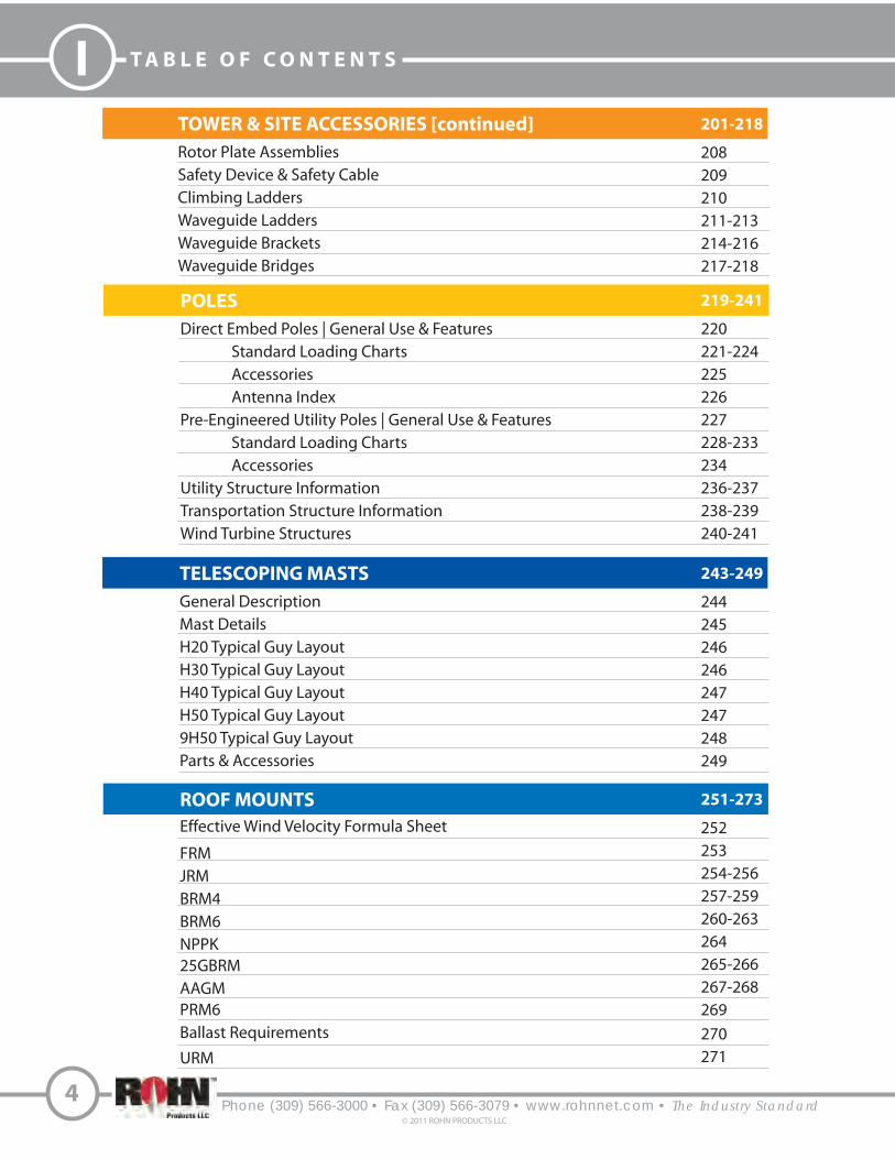
TOWER & SITE ACCESSORIES [continued]
Rotor Plate Assemblies
Safety Device & Safety Cable
Climbing Ladders
Waveguide Ladders
Waveguide Brackets
Waveguide Bridges
201-218
208
209
210
211-213
214-216
217-218
219-241
220
221-224
225
226
227
228-233
234
236-237
238-239
240-241
243-249
244
245
246
246
247
247
248
249
251-273
252
253
254-256
257-259
260-263
264
265-266
267-268
269
270
271
T A B L E O F C O N T E N T S I
Phone (309) 566-3000 • Fax (309) 566-3079 • www.rohnnet.com • The Industry Standard© 2011 ROHN PRODUCTS LLC
5
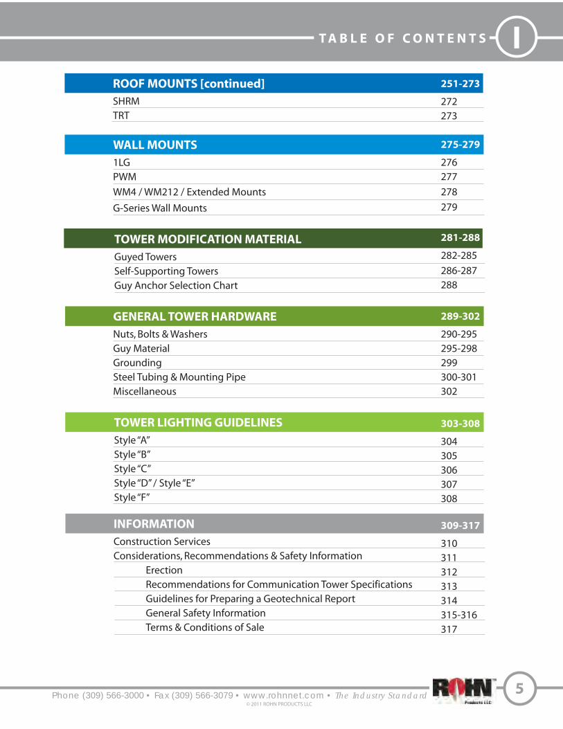
INFORMATION
Construction Services
Considerations, Recommendations & Safety Information
Erection
Recommendations for Communication Tower Specifications
Guidelines for Preparing a Geotechnical Report
General Safety Information
Terms & Conditions of Sale
GENERAL TOWER HARDWARE
Nuts, Bolts & Washers
Guy Material
Grounding
Steel Tubing & Mounting Pipe
Miscellaneous
TOWER LIGHTING GUIDELINES
Style “A”
Style “B”
Style “C”
Style “D” / Style “E”
Style “F”
ROOF MOUNTS [continued]
SHRM
TRT
WALL MOUNTS
1LG
PWM
WM4 / WM212 / Extended Mounts
G-Series Wall Mounts
251-273
272
273
275-279
276
277
278
279
281-288
282-285
286-287
288
289-302
290-295
295-298
299
300-301
302
303-308
304
305
306
307
308
309-317
310
311
312
313
314
315-316
317
TOWER MODIFICATION MATERIAL
Guyed Towers
Self-Supporting Towers
Guy Anchor Selection Chart

I T H E C O M P A N Y
Phone (309) 566-3000 • Fax (309) 566-3079 • www.rohnnet.com • The Industry Standard© 2011 ROHN PRODUCTS LLC
6
H I S T O R Y
Founded in 1948, in Peoria, Illinois by Dwight Rohn, the ROHN product quickly became
the industry standard for towers. The need for ROHN structures grew out of the television
industry and a need for homeowners to have small towers adjacent to their homes to
enable signal reception. The demand grew quickly and the company’s knowledge and
capacity were forced to grow with it. Soon television reception towers grew into radio
towers, microwave towers, lighting structures and more. When the cellular technology
exploded in the U.S., ROHN was there to provide the towers to support the rapid growth.
This growth was not just in markets but in geographies.
By 1980, ROHN had structures standing on every continent and in nearly every country
on the globe. We continue to supply towers and poles to all of the communication giants
and regional carriers. We support utilities and transportation in all of North America. We
have wind turbine towers and meteorological towers across the globe. For over 60 years,
our products have endured and our name continues to be recognized around the world
as the industry standard.

B R O A D C A S T S O L U T I O N S
Phone (309) 566-3000 • Fax (309) 566-3079 • www.rohnnet.com • The Industry Standard
IR O H N S O L U T I O N S
7© 2011 ROHN PRODUCTS LLC
When Americans turned on their !rst television sets, ROHN was there
to improve fuzzy reception with our home antenna tower. During the
40’s and 50’s, a ROHN TV tower installed on a rooftop or in a backyard
meant that family’s TV reception was the best on the block, even if the
picture was only black and white and the screen just 12 inches wide.
ROHN’s business serves the broadcast side of TV as well. With the advent
of digital TV and compliance with FCC standards, broadcasters are
choosing to remain competitive by expanding their services into more
areas. To do so, they look to ROHN to deliver “Tall Towers”, super structures
rising as high as 2,000 feet, to broadcast TV signals to millions of viewers
in a much wider geographic area.
ROHN towers are some of the tallest structures in the world, and we build
each tower in accordance with our exacting standards for quality,
performance and structural integrity. Our tall towers are helping change
the way the world receives and views television signals. This innovation
is nothing new for ROHN. Back in 1948 when we started our business,
we were on the forefront of the television age. Today, we stand ready to
serve the next wave of television broadcasting.

R O H N S O L U T I O N S
W I R E L E S S S O L U T I O N S
Phone (309) 566-3000 • Fax (309) 566-3079 • www.rohnnet.com • The Industry Standard8
© 2011 ROHN PRODUCTS LLC
I
ROHN has been supplying towers to the wireless industry since the industry
was born. Whether the application is microwave, cellular, PCS or broadband,
we have the towers in service supporting wireless communications.
When the !rst microwave towers were constructed in the United States,
ROHN was the quality supplier of choice. We designed and fabricated to the
most stringent standards for wind, ice and dish twist and sway requirements.
As the communication system progressed to cellular, then PCS, ROHN was
again leading the market with our ROHN SSV towers serving as the industry
preference for wireless sites.
ROHN continues to support wireless communication from microwave to
broadband communications. Our structures are still the leaders in the industry.
ROHN also o#ers a variety of steel poles to meet your speci!c communication
needs. Our tapered and $anged steel poles feature designs that are
aesthetically pleasing and blend well into the environment while requiring
minimum space for installation. All of our steel poles are hot-dip galvanized
after fabrication to ensure years of corrosion free use. As one of the largest
manufacturers of communication structures, with unmatched attention to
detail and design, our steel poles provide an extremely e%cient design.
ROHN’s steel poles meet the stringent demands of today’s communication
environment.

S P O R T S L I G H T I N G S O L U T I O N S
Phone (309) 566-3000 • Fax (309) 566-3079 • www.rohnnet.com • The Industry Standard
IR O H N S O L U T I O N S
9© 2011 ROHN PRODUCTS LLC
Whatever your application - from little league baseball to a major league
sports stadium, ROHN has a steel pole to do the job. Poles are available
with the traditional anchor base or for direct embedment. ROHN’s
engineering sta! will select the proper pole based on your speci#c
requirements, considering wind speed, luminaire size, weight and quantity.
For decades, ROHN has supplied sports lighting structures. ROHN towers
support lights for the Anaheim Angels professional baseball team, the
University of Illinois football team and the Peoria Chiefs, the local minor
league baseball team near our plant location in Peoria, IL.
All poles and towers are hot-dip galvanized and our direct embed poles
can be purchased with an extra subsurface corrosion resistant coating.

Phone (309) 566-3000 • Fax (309) 566-3079 • www.rohnnet.com • The Industry Standard
I R O H N S O L U T I O N S
T R A N S P O R T A T I O N S O L U T I O N S
10
© 2011 ROHN PRODUCTS LLC
ROHN has been a trusted name in quality-engineered structures since
1948. We have the people, equipment and experience to provide the
materials you need for your transportation structure projects. ROHN
Mast Arms, Monotube Assemblies, Steel Strain Poles and Sign Structures
are designed and manufactured to AASHTO standards. Our products can
be supplied galvanized, painted over galvanizing or factory !nished
powder coated. We are dedicated to delivering quality products, on time
at a competitive price; whether it is a single pole or multiple pole project.
ROHN has over 300,000 square feet of manufacturing located in Peoria,
Illinois. ROHN’s manufacturing is certi!ed by both the American Institute
of Steel Construction (Dual AISC Certi!ed Steel Fabricator - Buildings
and Simple Steel Bridges) and the Canadian Welding Bureau.
ROHN uses specialized engineering software coupled with ROHN developed
software for the design of tubular structures and foundations. This
allows ROHN to optimize pole designs based on customer requirements,
manufacturing e#ciencies and material availability. Preliminary
calculation packages are sent to our customers for review with bid
packages.
Phone (309) 566-3000 • Fax (309) 566-3079 • www.rohnnet.com • The Industry Standard11
© 2011 ROHN PRODUCTS LLC
U T I L I T Y S O L U T I O N S
IR O H N S O L U T I O N S
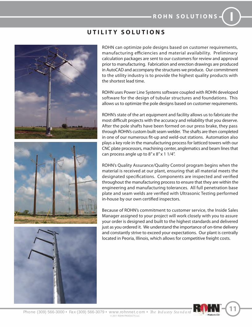
ROHN can optimize pole designs based on customer requirements,
calculation packages are sent to our customers for review and approval
prior to manufacturing. Fabrication and erection drawings are produced
in AutoCAD and accompany the structures we produce. Our commitment
to the utility industry is to provide the highest quality products with
the shortest lead time.
ROHN uses Power Line Systems software coupled with ROHN developed
software for the design of tubular structures and foundations. This
allows us to optimize the pole designs based on customer requirements.
ROHN’s state of the art equipment and facility allows us to fabricate the
After the pole shafts have been formed on our press brake, they pass
through ROHN’s custom built seam welder. The shafts are then completed
plays a key role in the manufacturing process for latticed towers with our
CNC plate processors, machining center, anglematics and beam lines that
can process angle up to 8” x 8” x 1 1/4”.
ROHN’s Quality Assurance/Quality Control program begins when the
material is received at our plant, ensuring that all material meets the
throughout the manufacturing process to ensure that they are within the
engineering and manufacturing tolerances. All full penetration base
Because of ROHN’s commitment to customer service, the Inside Sales
Manager assigned to your project will work closely with you to assure
your order is designed and built to the highest standards and delivered
just as you ordered it. We understand the importance of on-time delivery
and constantly strive to exceed your expectations. Our plant is centrally
located in Peoria, Illinois, which allows for competitive freight costs.

Phone (309) 566-3000 • Fax (309) 566-3079 • www.rohnnet.com • The Industry Standard
I R O H N S O L U T I O N S
W I N D E N E R G Y S O L U T I O N S
12
© 2011 ROHN PRODUCTS LLC
ROHN has extensive experience in manufacturing meteorological and
turbine support structures for wind energy applications. Whatever the
requirement, poles, towers or guyed masts, we have used our products
to support this industry.
Our structures are used to support wind turbines ranging up to 50 kW.
ROHN structures are hot-dip galvanized where the components are
totally immersed in molten zinc, inside and out, to ensure years of corrosion
protection. Our steel pole designs are aesthetically pleasing, while requiring
minimum space for installation.
To ensure that ROHN meets the demand of today’s wind energy customer,
our steel poles o!er extremely e#cient designs and unmatched attention
to detail. For over 60 years, ROHN has manufactured support structures
with great care and design excellence.


Phone (309) 566-3000 • Fax (309) 566-3079 • www.rohnnet.com • The Industry Standard
I R O H N S O L U T I O N S
U N D E R S T A N D I N G T I A - 2 2 2 - R E V I S I O N G
14
© 2011 ROHN PRODUCTS LLC
What is Rev G?
Rev G is the latest revision of the TIA-222 Standard “Structural Standards for Antenna Supporting Structures and Antennas”.
The previous version of the Standard was Rev F. Rev G is based on a 3-second gust wind speed and Rev F is based on a fastest-
mile wind speed. The wind speeds are not directly comparable and it is very important to de!ne the basis of a wind speed
when specifying wind loading requirements. For a given location, the 3-second gust wind speed represents the peak gust
wind speed whereas the fastest-mile wind speed represents the average wind speed over the time required for one mile of
wind to pass the site.
Rev G presents additional factors to be considered in the design of new structures and for the modi!cation of existing
structures. These factors are brie#y discussed below. The reliability requirements of a structure can now be accounted for by
assigning a classi!cation to a structure (Class I, II or III). The wind speed can also be adjusted based on the type of terrain
surrounding the site (Exposure B, C or D) and if the site is located on a hill, ridge or escarpment (Topographic Category 1-5).
Many tower pro!les in this catalog now include antenna loading capacities for both Exposure B and Exposure C terrain
conditions located on relatively #at sites (Topographic Category 1). Antenna loading capacities in accordance with Rev F
are also provided for many tower pro!les in the catalog. Please refer to the design notes in the catalog for each tower model
series for further explanations. The Class of structure is stated in the design notes. Conditions other than stated may require
a di$erent tower pro!le than illustrated in this catalog. Quotes may be obtained for a speci!c application by contacting your
ROHN representative.
Classi"cation of Structures
Allows for the adjustment of wind, ice and earthquake loading to match the reliability requirements for a speci!c application.
Three reliability classes have been established based on the type of service provided and on the structure’s potential
hazard to human life and property. Wind, ice and earthquake loading progressively increase from Class I to Class III structures.
Class I: Structures used for services where a delay in returning the service would be acceptable and the structure represents a
low hazard to human life and/or property. Example services would be: residential wireless and conventional 2-way radio
communications; television, radio and scanner reception; wireless cable, amateur and CB radio communications. Structures
of this classi!cation are exempt from ice and earthquake loading.
Class II: Structures used for services that may be provided by other means or structures that represent a signi!cant hazard to
human life and/or property. Example services would be: commercial wireless communications; television and radio
broadcasting; cellular, PCS, CATV and microwave communications.
Class III: Structures speci!cally designed for essential communications or structures that represent a substantial hazard to
human life and/or property. Examples of essential communications would be: civil or national defense; emergency, rescue
or disaster operations; military and navigational facilities.
What is EPA?
EPA stands for E$ective Projected Area. It is a standard way to de!ne the “size” of an antenna regarding wind loading. Many
antenna manufacturers provide data sheets that specify the EPA of their antennas. The TIA standard also de!nes a method
to calculate the EPA of an antenna based on the size and type of the antenna components.
Generally, the EPA of an antenna, mount or accessory is equal to the summation of the projected areas of its components times
appropriate drag factors de!ned in the TIA Standard. The EPA values listed in this catalog for standard tower designs represents
the maximum EPA that may be supported unless otherwise indicated.

U N D E R S T A N D I N G T I A - 2 2 2 - R E V I S I O N G
Phone (309) 566-3000 • Fax (309) 566-3079 • www.rohnnet.com • The Industry Standard
IR O H N S O L U T I O N S
15© 2011 ROHN PRODUCTS LLC
What is Exposure?
Exposure categories are used to adjust wind loading based on the type of terrain surrounding a site. Reduced wind loads are
associated with rougher terrains that tend to slow the wind down. Three exposure categories have been de!ned based on
terrain roughness. Wind loading is increased as the exposure designation changes from Exposure B (roughest terrain) to
Exposure D (smoothest terrain).
Exposure B: Urban, suburban or wooded areas. The wind load at ground level is reduced compared to Exposure C. This
reduction diminishes with height, making the overall wind reduction less signi!cant for taller structures. In order to qualify for
the wind load reduction, the rough terrain must extend in all directions from the site at least twenty times the height of the
structure, but not less than one-half mile.
Exposure C: Flat, open country and grasslands.
Exposure D: Flat, unobstructed shorelines exposed to wind #owing over open water, smooth mud #ats, salt #ats and other
similar terrain. The wind load at ground level is increased compared to Exposure C.
Topographic Categories
Topographic categories are used to determine increases in wind loading for sites located on hills and other elevated locations
(other than buildings). The shape and relative height (topography) of an elevated site determines the increase in wind load.
Although many elevated sites have their own unique features, the intent is to idealize these sites into one of the standard
topography categories described below.
The height of an elevated site above the surrounding terrain must be speci!ed in order to determine the increase in wind
loading. Height should not be confused with the elevation of the site. As described below, elevations of the site and the
surrounding terrain must be used to determine the relative height of a site. For structures supported on buildings, it is only
necessary to specify the height of the building and the surrounding exposure category.
Category 1: Flat or rolling terrain with no abrupt changes in general topography. No increase in wind loading is required for
this category.
Category 2: Sites separated from a lower elevation by a gently sloping terrain (escarpment). Wind loads at the crest are 2.0
times the wind loads for a #at site and diminish with height depending on the height of the escarpment.
Height for an escarpment is the di$erence in elevation between the upper and lower levels. Increased wind loads do not apply
for structures located in the lower half of the sloping terrain or located beyond 16 times the escarpment’s height from the crest.
Category 3: Sites located at the top or within the upper half of a hill. Wind loads at the top of a hill are 2.3 times the wind loads
for a #at site and diminish with height depending on the relative height of the hill.
Height for a hill is the di$erence in elevation between the top and bottom of the hill. For sites surrounded by other hills, height
is the di$erence in the hill elevation at the site and the average elevation of the surrounding hills (within a 2-mile radius).
In other words, height is the projection of the hill exposed to wind. When there are other hills surrounding the site, increased
wind loads do not apply unless the height of the hill at the tower site is at least 2 times the average height of the surrounding
hills. (Refer to sketch above.)
Topographic Categories continued on next page.

Phone (309) 566-3000 • Fax (309) 566-3079 • www.rohnnet.com • The Industry Standard
I R O H N S O L U T I O N S
U N D E R S T A N D I N G T I A - 2 2 2 - R E V I S I O N G
16
© 2011 ROHN PRODUCTS LLC
Elevation 2,150’
Elevation 1,550’
Elevation 1,250’
Average Elevation of
Surrounding Features
2 Mile Radius 2 Mile Radius
30
0’
60
0’
H = 2,150’ - 1,550‘ = 600’
Wind speed-up must be considered when H exceeds
2 times the average height of surrounding features.
Category 4: Sites located on a ridge. Wind loads at the top of a ridge are 3 times the wind loads for a !at site and diminish with
height depending on the height of the ridge.
Height for a ridge is the di#erence between the top and bottom elevations of the ridge.
Category 5: This category is reserved for sites where site-speci$c investigations are performed to determine wind loading. A
site-speci$c investigation may result in either higher or lower wind loads compared to using one of the standard topographic
categories.
Height of Site
Average Height
of Surrounding
Terrain
Tower

Phone (309) 566-3000 • Fax (309) 566-3079 • www.rohnnet.com • The Industry Standard
IR O H N S O L U T I O N S
17© 2011 ROHN PRODUCTS LLC
Special Wind Region
Location V mph (m/s)
Hawaii 105 (47)
Puerto Rico 145 (66)
Guam 170 (76)
Virgin Islands 145 (65)
American Samoa 125 (56)
Notes:
1. Values are 3-second gust wind speeds in miles per hour (m/s) at 33 ft. (10 m) above ground for Exposure C terrain.2. Linear interpolation between wind contours is permitted.3. Islands and coastal areas outside last contour must use the last wind speed contour of the coastal area.4. Mountainous terrain, gorges, ocean promontories, and special wind regions must be examined for unusual wind conditions.
R E V G 3 - S E C O N D B A S I C W I N D S P E E D M A P
The basic wind speed map is being used with permission from ASCE. This material may be used for personal use only.
Any other use requires prior permission of the American Society of Civil Engineers.

Phone (309) 566-3000 • Fax (309) 566-3079 • www.rohnnet.com • The Industry Standard
I R O H N S O L U T I O N S
R E V G W I N D S P E E D S
18
© 2011 ROHN PRODUCTS LLC
The TIA-222-G Standard is based on the wind map published in the ASCE 7-02 Standard, “Minimum Design Loads for Buildings
and Other Standards”. The ASCE 7 standard is published by the American Society of Civil Engineers (ASCE) and represents the
latest research and data available for wind speeds in the United States.
Subsequent to the release of the TIA-222-G Standard, ASCE has published 2 revisions to the ASCE-7 Standard. The !rst revision
was published in 2005 and is designated as ASCE 7-05. There were no changes to the wind map. The second revision was
published in 2010 and is designated as ASCE 7-10. There are changes to the wind map in this version.
The previous versions of ASCE 7 used a 50-year return wind speed map and relied on additional design factors to increase
wind loads according to the reliability requirements of a structure. This resulted in structures being able to survive wind
speeds of much higher return periods. The new wind maps in ASCE 7 -10 now include these design factors and now
represent a much higher return period wind speed. A wind map is provided for each classi!cation of structure. No
additional factors have to be considered based on the classi!cation of a structure when these wind speeds are used to
calculate wind loads. The new maps can be thought of as “Survival” wind speeds, or in other words, wind speeds for
which permanent deformation may occur in a structure, but the structure does not collapse.
The new ASCE 7-10 survival wind speeds can be easily converted for use with the TIA-222-G Standard using the following
conversion table. If the conversion is not made, the design factors for determining wind loads will be “doubled up” resulting
in much higher wind loads than intended. Eventually the TIA Standard and other similar structural standards will be
upgraded to re#ect the new ASCE 7-10 wind maps. Conversions for fastest-mile wind speeds used in Rev F and
ASCE 7-93 are also included in the table.
Examples to determine appropriate Rev G design criteria:
1. Desire a 95 mph Rev F fastest-mile design. Use a 110 mph Rev G design.
2. Desire a 115 mph ASCE 7-10 design. Use a 90 mph Rev G design.
Design Wind Speed Conversions, MPH
Rev F
ASCE 7-93
(fastest-mile)
71
76
85
90
95
104
114
123
128
133
152
Rev G
ASCE 7-02 & ASCE 7-05
(3-second gust)
85
90
100
105
110
120
130
140
145
150
170
Survival
ASCE 7-10
(3-second gust)
110
115
126
133
139
152
164
177
183
190
215

Phone (309) 566-3000 • Fax (309) 566-3079 • www.rohnnet.com • The Industry Standard
IR O H N S O L U T I O N S
19© 2011 ROHN PRODUCTS LLC
R E V G G R O U N D I N G
R E Q U I R E M E N T F O R S T R U C T U R E S
Rev G made signi!cant changes regarding the grounding requirements for structures. A prescriptive approach to grounding
was used in Rev F where providing speci!c grounding leads and ground rods were considered adequate to protect a structure.
Rev G adopted a performance speci!cation approach that requires providing a grounding system that will result in a maximum
10 ohm resistance to earth. Rev G also requires minimum ground lead and ground rod sizes that are greater than the Rev F
prescriptive requirements.
Another change is that Rev G does not require speci!c grounding materials. Rev F required the use of galvanized ground rods
with tinned copper leads. Rev G only requires that the leads and connections be compatible with the ground rods from a
corrosion standpoint (i.e. minimize di#erence between metals connected).
Rev G does provide default grounding arrangements for various types of structures that are intended to meet the 10 ohm
requirement for a wide variety of soil conditions. In accordance with Rev G, the actual resistance of a default grounding system
must be veri!ed based on site conditions. Additional ground rods or special grounding systems may be required.
It should be noted that the TIA-222 grounding requirements are meant to protect the structure and foundation from high
fault currents. Other grounding requirements are often needed for the protection of antennas, radio equipment and other
appurtenances.
Rev G has taken a di#erent approach from Rev F regarding standard foundations and the term “Normal Soil” has been
eliminated. A new term “Presumptive Soil” has been introduced. Rev G provides for two di#erent types of presumptive soil,
sand and clay. Generally the strength of Rev G presumptive soil is lower than the strength of Rev F normal soil.
The intent is to provide default design parameters that can be used to design foundations when a geotechnical report is not
available for a site. In accordance with Rev G, clay is to be considered the default presumptive soil unless more information is
known about a site. The values for clay presumptive soil have therefore been used for the generation of the standard
foundations contained in this catalog.
It should be noted that in accordance with Rev G, actual site conditions must be investigated prior to the installation of a
foundation that was designed using presumptive soil parameters. Modi!cations to the standard foundations contained in
this catalog may be required. It should also be noted that Rev G requires a geotechnical investigation for all Class III structures.
One common cause for changes to a standard foundation is due to frost depth. The frost depth for Rev G presumptive soil is
considered to be 3.5 feet. The standard foundations in this catalog are based on this frost depth. Special foundations may be
required for sites in locations where frost depths exceed 3.5 feet and the local soil conditions are susceptible to frost heave.
Presumptive soil also assumes that the water table is below the foundation depth. For this condition, there is no concern for
buoyant conditions that can signi!cantly reduce the uplift capacity of a foundation. The standard foundations in this catalog
are based on dry soil conditions and do not consider buoyant conditions. Special foundations may be required for sites where
the water table may rise above the base elevation of the foundation.
In accordance with Rev G, presumptive soils are also considered to be non-corrosive. When local soil conditions are corrosive,
anchors or direct embedded poles that are in direct soil contact may require corrosion protection in addition to hot dip
galvanizing. Rev G provides guidance on various alternatives to consider in these situations.
Presumptive soils are also considered to be non-expansive. Locations known to have expansive soil require special
considerations for foundation design. Modi!cations to the standard foundations in this catalog may be required in these
cases.
R E V G S T A N D A R D F O U N D A T I O N S

Phone (309) 566-3000 • Fax (309) 566-3079 • www.rohnnet.com • The Industry Standard
I R O H N S O L U T I O N S
R E V G C L I M B I N G F A C I L I T I E S
20
© 2011 ROHN PRODUCTS LLC
Rev G has made signi!cant additions addressing climber safety. Two classi!cations of climbers have been de!ned.
An Authorized Climber (also called a Basic Climber) is an individual trained in climbing but may not have had previous
climbing experience. These climbers are intended to be limited to climbing !xed access routes equipped with safety climb
devices. A Competent Climber (also called a Skilled Climber) is a professional who is capable of climbing on structural
members.
Rev G provides requirements for climbing facilities by de!ning two classes of climbing facilities, Class A and Class B.
Class B requirements are similar to Rev F requirements and are intended for structures to be climbed by professional
Competent Climbers. Class A requirements are more restrictive in comparison to Rev F and are intended for structures
expected to be climbed by lesser quali!ed (Basic) climbers. In accordance with Rev G, Class B is considered to be the
default climbing facility requirement for structures unless otherwise speci!ed. Towers can be quoted to accomodate
Class A climbing facilities when speci!ed. All ROHN standard structures are intended to be climbed by Competent
Climbers only.
Safety climb systems are now mandatory in accordance with Rev G for structures exceeding 10 feet in height that are
intended to be climbed. Some structures are intended to be maintained by bucket trucks or other methods that do not
involve climbing the structure. Safety climb systems, when required, must be ordered separately for all ROHN standard
structures in this catalog.

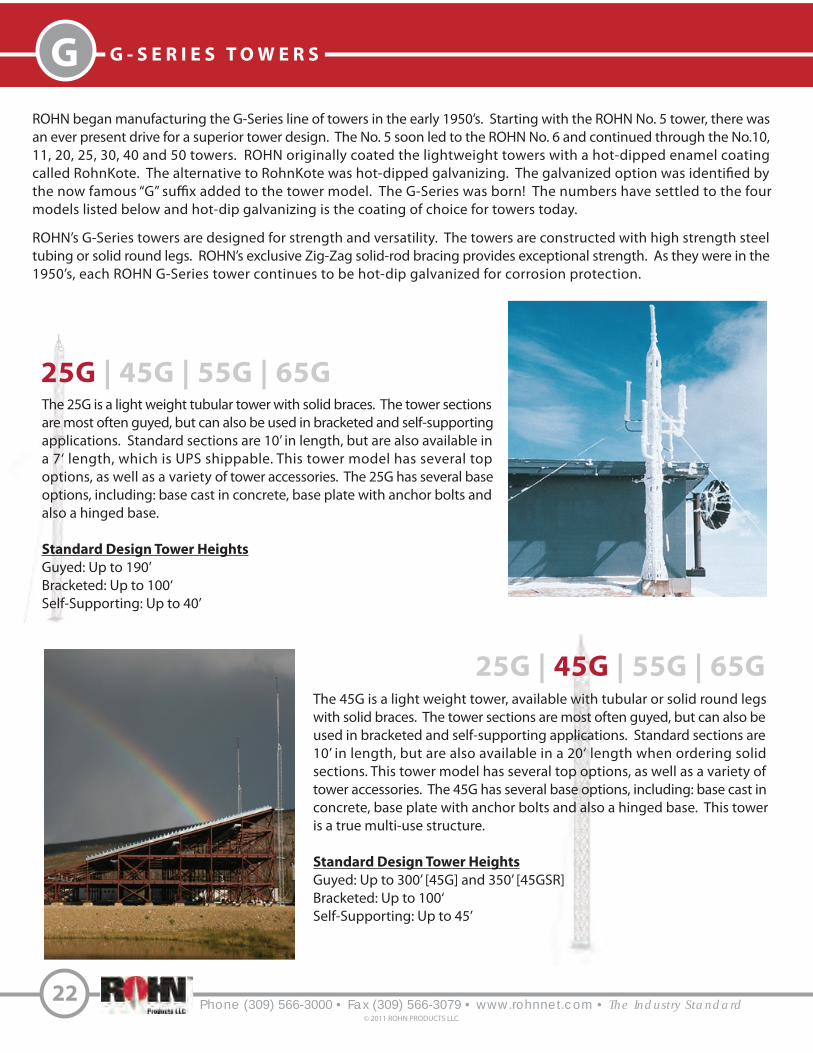
The 25G is a light weight tubular tower with solid braces. The tower sections
are most often guyed, but can also be used in bracketed and self-supporting
applications. Standard sections are 10’ in length, but are also available in
a 7‘ length, which is UPS shippable. This tower model has several top
options, as well as a variety of tower accessories. The 25G has several base
options, including: base cast in concrete, base plate with anchor bolts and
also a hinged base.
Standard Design Tower Heights
Guyed: Up to 190’
Bracketed: Up to 100‘
Self-Supporting: Up to 40’
25G | 45G | 55G | 65G
The 45G is a light weight tower, available with tubular or solid round legs
with solid braces. The tower sections are most often guyed, but can also be
used in bracketed and self-supporting applications. Standard sections are
10’ in length, but are also available in a 20‘ length when ordering solid
sections. This tower model has several top options, as well as a variety of
tower accessories. The 45G has several base options, including: base cast in
concrete, base plate with anchor bolts and also a hinged base. This tower
is a true multi-use structure.
Standard Design Tower Heights
Guyed: Up to 300’ [45G] and 350’ [45GSR]
Bracketed: Up to 100‘
Self-Supporting: Up to 45’
25G | 45G | 55G | 65G
Phone (309) 566-3000 • Fax (309) 566-3079 • www.rohnnet.com • The Industry Standard
G G - S E R I E S T O W E R S
22
© 2011 ROHN PRODUCTS LLC
ROHN began manufacturing the G-Series line of towers in the early 1950’s. Starting with the ROHN No. 5 tower, there was
an ever present drive for a superior tower design. The No. 5 soon led to the ROHN No. 6 and continued through the No.10,
11, 20, 25, 30, 40 and 50 towers. ROHN originally coated the lightweight towers with a hot-dipped enamel coating
called RohnKote. The alternative to RohnKote was hot-dipped galvanizing. The galvanized option was identi!ed by
the now famous “G” su#x added to the tower model. The G-Series was born! The numbers have settled to the four
models listed below and hot-dip galvanizing is the coating of choice for towers today.
ROHN’s G-Series towers are designed for strength and versatility. The towers are constructed with high strength steel
tubing or solid round legs. ROHN’s exclusive Zig-Zag solid-rod bracing provides exceptional strength. As they were in the
1950’s, each ROHN G-Series tower continues to be hot-dip galvanized for corrosion protection.

Phone (309) 566-3000 • Fax (309) 566-3079 • www.rohnnet.com • The Industry Standard© 2011 ROHN PRODUCTS LLC
23
GG - S E R I E S T O W E R S
The 55G is a tubular tower with solid braces that lends itself to a wide variety
of uses, particularly where unusual wind loading and height requirements
exist. The 55G was designed to provide excellent strength and rigidity. The
tower sections are most often guyed, but can also be used in bracketed and
self-supporting applications. Standard sections are 10’ in length. This tower
model has several top options, as well as a variety of tower accessories.
The 55G is available with a base cast in concrete as well as a tapered base
option.
Standard Design Tower Heights
Guyed: Up to 400’
Bracketed: Up to 100‘
Self-Supporting: Up to 60’
The 65G is available with tubular or solid round legs with solid braces. The
tower sections are most often guyed, but can also be used in self-supporting
applications. Standard sections are 10’ and 20’ in length. This tower model
has a variety of tower accessories, and is available with a base cast in concrete
or a tapered base.
Standard Design Tower Heights
Guyed: Up to 500’
Self-Supporting: Up to 80’
25G | 45G | 55G | 65G
25G | 45G | 55G | 65G
The ROHN G-Series towers are assembled and installed quickly and are diverse enough for use by broadcasters, !re and
police, military, ham and home use. The possibilities are endless with the G-Series towers. Over the long history of the
G-Series, ROHN has developed a variety of options to improve the utility of each model. The G-Series has optional:
• Standard and Shortened Sections • Double Braced Sections • House Brackets• Guy Lug Sections • Torque Arms • Base Options • Four Leg (Square) Design of 25G • Roof Mounts • Side Arms • Double Braced Sections • Top Mounts

Phone (309) 566-3000 • Fax (309) 566-3079 • www.rohnnet.com • The Industry Standard
G G U Y E D T O W E R S - 2 5 G
S T A N D A R D 2 5 G G U Y E D T O W E R
24© 2011 ROHN PRODUCTS LLC
The first. The original.ROHN 25G
Per Rev G requirements, any structure greater than 10’ requires a climber
safety device. Please see page 40 for ordering information.
REV. G
includes
REV. F &
GENERAL USE
The 25G is available in the standard 10’ section
length and a 7’ length which is UPS shippable.
The 25G uses double bolted joints, proven to be
the best method of joining tower sections for
sturdiness and dependability. As a guyed
structure, the 25G standard designs rise to a
height of 190’.
FEATURES
• Completely hot-dip galvanized after fabrication
• Built on an 11 1/4” equilateral triangle design
• High strength tubular legs joined by Zig-Zag®
cross members
• Each 7’ or 10’ section contains all required nuts
and bolts shipped with section
• Continuous solid round steel bracing
25G
Mixing copies of ROHN towers with ROHN towers is dangerous and voids all engineering and warranty data supplied by ROHN. Materials used by others are not the same quality and have not been tested or engineered by ROHN. MixingROHN tower sections with non-ROHN products may cause tower failure or injury.
CAUTION

1 1/4” O.D.(16 GA.)
9’ 9”
1’ 6”
STANDARD SECTION
25G - 10’ Section
OPTIONAL 7’ SECTION
25G7 - 7‘ SectionThe 7’ Section is UPS shippable.
Phone (309) 566-3000 • Fax (309) 566-3079 • www.rohnnet.com • The Industry Standard
GG U Y E D T O W E R S - 2 5 G
S T A N D A R D 2 5 G G U Y E D T O W E R
S E C T I O N S
25
2.25” O.D.2.08” I.D.(14 GA.)
9 3/4”6 1/2”
11 1/4”
1 1/4” O.D.(16 GA.)
5/16” O.D.Solid Bracing
STANDARD TOP SECTION
25AG2
Additional 25G top sectionsare shown on page 37.
5/16” O.D.Solid Bracing
© 2011 ROHN PRODUCTS LLC
PARTS & ACCESSORIES PAGES 37-40GROUNDING INFORMATION PAGE 41FOUNDATION INFORMATION PAGES 41-44
QUICK REFERENCE
CONCRETE BASE PLATE
BPC25G*FOR USE WITH 3/4X12PP PIER PIN
EMBEDDED IN CONCRETE.
Additional base sections are available, please see page 38.
1’ 3”
Optional double braced sections are available upon request.
Optional WaveguideBrackets (KY2041A)
* Towers mounted on these bases must be bracketed or guyed at all times. Temporary steel guying may also be necessary during installation and dismantling.
~~

This document is to serve as a guide for sizing and purchasing the 25G tower. Tower and foundation installations should be performed by qualified and experienced personnel using assembly drawings provided with each tower.
DESIGN NOTES:
1. Tower designs are in accordance with ANSI/TIA-222-F and ANSI/TIA-222-G, Class I Structures, Topographic Category 1. 2. Design assumes towers are installed on level ground. Lower EPA values will apply for roof mounted towers or for sites located on unusual terrain. 3. Designs assume two 1/2” diameter lines on each tower face. 4. Anchor radius is from tower base to intersection of anchor rod with ground. 5. Guy chord lengths shown are based on level ground. Initial tensions for guys are shown in ( ) in pounds at 60º Fahrenheit. 6. Antenna and mounts are assumed symmetrically placed at the tower top.
PARTS LIST NOTES:
1. Items listed are required for complete guyed towers. 2. Base and anchor foundations listed refer to standard foundation designations. 3. Guys provided with each standard tower are based on level ground conditions with an additional 6% length. 4. Rev G anchor grounding (AGK1GGX) and base grounding (BGK3GGX) are included with the tower material. 5. Assembly drawings and a safety package (P/N: ACWS) are included with each tower. 6. Parts lists are subject to change based on availability or revised design criteria.
FOR FOUNDATION INFORMATION, PLEASE SEE PAGES 41-44.
FOR GENERAL INSTALLATION INFORMATION, PLEASE SEE PAGES 147-153.
EPA (SQ. FT.) For Exposure B, Revision G
EPA (SQ. FT.) For Exposure C, Revision G
EPA (SQ. FT.), Revision F
P/N 25G90R040
47’
35’
32’
3/16” EHS(399#)
16.6
22.0
Phone (309) 566-3000 • Fax (309) 566-3079 • www.rohnnet.com • The Industry Standard
G G U Y E D T O W E R S - 2 5 G
22.6
B U Y E R S G U I D ES T A N D A R D D E S I G N S - 2 5 G
9 0 M P H R E V . G [ 3 - S E C O N D G U S T ]7 0 M P H R E V . F [ F A S T E S T M I L E ]
26
P/N 25G90R040
Tower ModelWindspeed (Rev. G) ROHN Tower
Tower Height (ft.)
EPA= Effective Projected Area
© 2011 ROHN PRODUCTS LLC
Guy Initial Tension
Design Criteria

TOWER PARTS
INCLUDED
GUYS &
CONNECTIONS
INCLUDED
ANCHORS &
GROUNDING
INCLUDED
25G 25AG2 BPC25G GA25GD
3/16EHS BG2142 5/16THH 1/2TBE&J TBSAFETY
GAC3455TOP AGK1GGX BGK3GGX CPC.5/.75
4 1 1 2
350’ 12 12 6 3
3 31 3
TOWER PARTS
INCLUDED
GUYS &
CONNECTIONS
INCLUDED
ANCHORS &
GROUNDING
INCLUDED
25G 25AG2 BPC25G GA25GD
3/16EHS BG2142 5/16THH 1/2TBE&J TBSAFETY
GAC3455TOP AGK1GGX BGK3GGX CPC.5/.75
5 1 1 2
425’ 12 12 6 3
3 31 3
TOWER PARTS
INCLUDED
GUYS &
CONNECTIONS
INCLUDED
ANCHORS &
GROUNDING
INCLUDED
25G 25AG2 BPC25G GA25GD
3/16EHS BG2142 5/16THH 1/2TBE&J TBSAFETY
GAC3455TOP AGK1GGX BGK3GGX CPC.5/.75
6 1 1 2
500’ 12 12 6 3
3 31 3
TOWER PARTS
INCLUDED
GUYS &
CONNECTIONS
INCLUDED
ANCHORS &
GROUNDING
INCLUDED
25G 25AG2 BPC25G GA25GD
3/16EHS BG2142 5/16THH 1/2TBE&J TBSAFETY
GAC3455TOP AGK1GGX BGK3GGX CPC.5/.75
7 1 1 3
800’ 18 18 9 3
3 31 3
P/N: 25G90R060
50’ ROHN 25G
Al l par ts shown in table
are included when order ing
Par t No: 25G90R050
60’ ROHN 25G
Al l par ts shown in table
are included when order ing
Par t No: 25G90R060
70’ ROHN 25G
Al l par ts shown in table
are included when order ing
Par t No: 25G90R070
80’ ROHN 25G
Al l par ts shown in table
are included when order ing
Par t No: 25G90R080
S T A N D A R D D E S I G N - 2 5 G
9 0 M P H R E V . G , 7 0 M P H R E V . F
TOWER PARTS
INCLUDED
GUYS &
CONNECTIONS
INCLUDED
ANCHORS &
GROUNDING
INCLUDED
25G 25AG2 BPC25G GA25GD
3/16EHS BG2142 5/16THH 1/2TBE&J TBSAFETY
GAC3455TOP AGK1GGX BGK3GGX CPC.5/.75
3 1 1 1
175’ 6 6 3 3
3 31 3
40’ ROHN 25G
Al l par ts shown in table
are included when order ing
Par t No: 25G90R040
P/N: 25G90R040
40’ TOWER
35’
22.6 16.6
22.0
OR
47’
32’
3/16” EHS(399#)
P/N: 25G90R050
50’ TOWER
45’
21.4 15.8
21.0
OR
60’
40’
3/16” EHS(399#)
46’23’
60’ TOWER
55’
20.3 15.2
20.2
OR
73’
48’
3/16” EHS(399#)
56’28’
P/N: 25G90R070
70’ TOWER
65’
19.4 14.7
19.4
OR
86’
56’
3/16” EHS(399#)
64’32’
P/N: 25G90R080
80’ TOWER
75’
18.6 14.3
18.8
OR
99’
64’
3/16” EHS(399#)
81’
50’
25’ 69’
Phone (309) 566-3000 • Fax (309) 566-3079 • www.rohnnet.com • The Industry Standard
GG U Y E D T O W E R S - 2 5 G
27
3/4x12PP
1
3/4x12PP
1
3/4x12PP
1
3/4x12PP
1
3/4x12PP
1
© 2011 ROHN PRODUCTS LLC
FDNS
BASE ANCHOR
FDNS
BASE ANCHOR
FDNS
BASE ANCHOR
FDNS
BASE ANCHOR
FDNS
BASE ANCHOR
CB1G AB2
AB2
AB2
AB2
AB2
CB1G
CB1G
CB1G
CB1G

TOWER PARTS
INCLUDED
GUYS &
CONNECTIONS
INCLUDED
ANCHORS &
GROUNDING
INCLUDED
25G 25AG2 BPC25G GA25GD
3/16EHS BG2142 5/16THH 1/2TBE&J TBSAFETY
GAC3455TOP AGK1GGX BGK3GGX CPC.5/.75
9 1 1 3
1000’ 18 18 9 3
3 31 3
TOWER PARTS
INCLUDED
GUYS &
CONNECTIONS
INCLUDED
ANCHORS &
GROUNDING
INCLUDED
25G 25AG2 BPC25G GA25GD
3/16EHS BG2142 5/16THH 1/2TBE&J TBSAFETY
GAC3455TOP AGK1GGX BGK3GGX CPC.5/.75
10 1 1 3
1100’ 18 18 9 3
3 31 3
TOWER PARTS
INCLUDED
GUYS &
CONNECTIONS
INCLUDED
ANCHORS &
GROUNDING
INCLUDED
25G 25AG2 BPC25G GA25GD
3/16EHS BG2142 5/16THH 1/2TBE&J TBSAFETY
GAC3455TOP AGK1GGX BGK3GGX CPC.5/.75
11 1 1 4
1575’ 24 24 12 3
3 31 3
TOWER PARTS
INCLUDED
GUYS &
CONNECTIONS
INCLUDED
ANCHORS &
GROUNDING
INCLUDED
25G 25AG2 BPC25G GA25GD
3/16EHS BG2142 5/16THH 1/2TBE&J TBSAFETY
GAC3455TOP AGK1GGX BGK3GGX CPC.5/.75
12 1 1 4
1700’ 24 24 12 3
3 31 3P/N: 25G90R130
100’ ROHN 25G
Al l par ts shown in table
are included when order ing
Par t No: 2590R100
110’ ROHN 25G
Al l par ts shown in table
are included when order ing
Par t No: 25G90R110
120’ ROHN 25G
Al l par ts shown in table
are included when order ing
Par t No: 25G90R120
130’ ROHN 25G
Al l par ts shown in table
are included when order ing
Par t No: 25G90R130
TOWER PARTS
INCLUDED
GUYS &
CONNECTIONS
INCLUDED
ANCHORS &
GROUNDING
INCLUDED
25G 25AG2 BPC25G GA25GD
3/16EHS BG2142 5/16THH 1/2TBE&J TBSAFETY
GAC3455TOP AGK1GGX BGK3GGX CPC.5/.75
8 1 1 3
900’ 18 18 9 3
3 31 3
90’ ROHN 25G
Al l par ts shown in table
are included when order ing
Par t No: 25G90R090
P/N: 25G90R090
90’ TOWER
85’
18.0 13.9
18.4
OR
111’
72’
3/16” EHS(399#)
92’
57’
28’ 77’
P/N: 25G90R100
100’ TOWER
95’
17.5 13.6
18.0
OR
124’
80’
3/16” EHS(399#)
102’
63’
31’ 86’
P/N: 25G90R110
110’ TOWER
105’
17.0 13.4
17.6
OR
137’
88’
3/16” EHS(399#)
112’
70’
35’ 95’
P/N: 25G90R120
120’ TOWER
115’
16.6 13.1
17.2
OR
150’
96’
3/16” EHS(399#)128’
85’
28’ 100’
55’111’
130’ TOWER
125’
16.2 12.9
17.0
OR
163’
104’
3/16” EHS(399#)140’
93’
31’ 108’
62’121’
Phone (309) 566-3000 • Fax (309) 566-3079 • www.rohnnet.com • The Industry Standard
G G U Y E D T O W E R S - 2 5 G
S T A N D A R D D E S I G N - 2 5 G
9 0 M P H R E V . G , 7 0 M P H R E V . F
28
3/4x12PP
1
3/4x12PP
1
3/4x12PP
1
3/4x12PP
1
3/4x12PP
1
© 2011 ROHN PRODUCTS LLC
FDNS
BASE ANCHOR
AB2
FDNS
BASE ANCHOR
AB2
FDNS
BASE ANCHOR
AB2
FDNS
BASE ANCHOR
AB2
FDNS
BASE ANCHOR
AB2
CB1G
CB1G
CB1G
CB1G
CB1G

Phone (309) 566-3000 • Fax (309) 566-3079 • www.rohnnet.com • The Industry Standard
GG U Y E D T O W E R S - 2 5 G
S T A N D A R D D E S I G N - 2 5 G
9 0 M P H R E V . G , 7 0 M P H R E V . F
29© 2011 ROHN PRODUCTS LLC
TOWER PARTS
INCLUDED
GUYS &
CONNECTIONS
INCLUDED
ANCHORS &
GROUNDING
INCLUDED
25G 25AG2 BPC25G GA25GD
3/16EHS BG2142 5/16THH 1/2TBE&J TBSAFETY
GAC3455TOP AGK1GGX BGK3GGX CPC.5/.75
13 1 1 4
1825’ 24 24 12 3
3 31 3P/N: 25G90R140
140’ ROHN 25G
Al l par ts shown in table
are included when order ing
Par t No: 25G90R140
140’ TOWER
135’
15.9 12.7
16.6
OR
175’
112’
3/16” EHS(399#)149’
99’
33’ 117’
66’130’
3/4x12PP
1
FDNS
BASE ANCHOR
AB2
TOWER PARTS
INCLUDED
GUYS &
CONNECTIONS
INCLUDED
ANCHORS &
GROUNDING
INCLUDED
25G 25AG2 BPC25G GA25GD
3/16EHS BG2142 5/16THH 1/2TBE&J TBSAFETY
GAC3455TOP AGK1GGX BGK3GGX CPC.5/.75
14 1 1 5
2425’ 30 30 15 3
3 31 3P/N: 25G90R150
150’ ROHN 25G
Al l par ts shown in table
are included when order ing
Par t No: 25G90R150
150’ TOWER
145’
15.5 12.5
16.4
OR
188’
120’
3/16” EHS(399#)
116’
29’
58’
3/4x12PP
1
FDNS
BASE ANCHOR
AB2
123’
133’
148’
167’87’
TOWER PARTS
INCLUDED
GUYS &
CONNECTIONS
INCLUDED
ANCHORS &
GROUNDING
INCLUDED
25G 25AG2 BPC25G GA25GD
3/16EHS BG2142 5/16THH 1/2TBE&J TBSAFETY
GAC3455TOP AGK1GGX BGK3GGX CPC.5/.75
15 1 1 5
2600’ 30 30 15 3
3 31 3P/N: 25G90R160
160’ ROHN 25G
Al l par ts shown in table
are included when order ing
Par t No: 25G90R160
160’ TOWER
155’
15.3 12.3
16.2
OR
201’
128’
3/16” EHS(399#)
124’
31’
62’
3/4x12PP
1
FDNS
BASE ANCHOR
AB2
132’
142’
158’
178’93’
TOWER PARTS
INCLUDED
GUYS &
CONNECTIONS
INCLUDED
ANCHORS &
GROUNDING
INCLUDED
25G 25AG2 BPC25G GA25GD
3/16EHS BG2142 5/16THH 1/2TBE&J TBSAFETY
GAC3455TOP AGK1GGX BGK3GGX CPC.5/.75
16 1 1 5
2750’ 30 30 15 3
3 31 3P/N: 25G90R170
170’ ROHN 25G
Al l par ts shown in table
are included when order ing
Par t No: 25G90R170
170’ TOWER
165’
15.0 12.2
16.0
OR
214’
136’
3/16” EHS(399#)
132’
33’
66’
3/4x12PP
1
FDNS
BASE ANCHOR
AB2
140’
151’
168’
190’99’
TOWER PARTS
INCLUDED
GUYS &
CONNECTIONS
INCLUDED
ANCHORS &
GROUNDING
INCLUDED
25G 25AG2 BPC25G GA25GD
3/16EHS BG2142 5/16THH 1/2TBE&J TBSAFETY
GAC3455TOP AGK1GGX BGK3GGX CPC.5/.75
17 1 1 5
2925’ 30 30 15 3
3 31 3P/N: 25G90R180
180’ ROHN 25G
Al l par ts shown in table
are included when order ing
Par t No: 25G90R180
180’ TOWER
175’
14.8 12.0
15.8
OR
227’
144’
3/16” EHS(399#)
139’
35’
69’
3/4x12PP
1
FDNS
BASE ANCHOR
AB2
148’
160’
178’
200’105’
CB1G
CB1G
CB1G
CB1G
CB1G

TOWER PARTS
INCLUDED
GUYS &
CONNECTIONS
INCLUDED
ANCHORS &
GROUNDING
INCLUDED
25G 25AG2 BPC25G GA25GD
3/16EHS BG2142 5/16THH 1/2TBE&J TBSAFETY
GAC3455TOP AGK1GGX BGK3GGX
18 1 1 5
3075’ 30 30 15 3
3 31
CPC.5/.75
3P/N: 25G90R190
190’ TOWER
185’
14.5 11.9
15.6
OR
239’
152’
3/16” EHS(399#)
212’
148’
37’ 156’
74’
188’
111’
169’
Phone (309) 566-3000 • Fax (309) 566-3079 • www.rohnnet.com • The Industry Standard
G G U Y E D T O W E R S - 2 5 G
S T A N D A R D D E S I G N - 2 5 G
9 0 M P H R E V . G , 7 0 M P H R E V . F
30
190’ ROHN 25G
Al l par ts shown in table
are included when order ing
Par t No: 25G90R190
3/4x12PP
1
© 2011 ROHN PRODUCTS LLC
FDNS
BASE ANCHOR
AB2CB1G

TOWER PARTS
INCLUDED
GUYS &
CONNECTIONS
INCLUDED
ANCHORS &
GROUNDING
INCLUDED
25G 25AG2 BPC25G GA25GD
3/16EHS BG2142 5/16THH 1/2TBE&J TBSAFETY
GAC3455TOP AGK1GGX BGK3GGX CPC.5/.75
4 1 1 2
350’ 12 12 6 3
3 31 3
TOWER PARTS
INCLUDED
GUYS &
CONNECTIONS
INCLUDED
ANCHORS &
GROUNDING
INCLUDED
25G 25AG2 BPC25G GA25GD
3/16EHS BG2142 5/16THH 1/2TBE&J TBSAFETY
GAC3455TOP AGK1GGX BGK3GGX CPC.5/.75
5 1 1 2
425’ 12 12 6 3
3 31 3
TOWER PARTS
INCLUDED
GUYS &
CONNECTIONS
INCLUDED
ANCHORS &
GROUNDING
INCLUDED
25G 25AG2 BPC25G GA25GD
3/16EHS BG2142 5/16THH 1/2TBE&J TBSAFETY
GAC3455TOP AGK1GGX BGK3GGX CPC.5/.75
6 1 1 2
500’ 12 12 6 3
3 31 3
TOWER PARTS
INCLUDED
GUYS &
CONNECTIONS
INCLUDED
ANCHORS &
GROUNDING
INCLUDED
25G 25AG2 BPC25G GA25GD
3/16 EHS BG2142 5/16 THH 1/2TBE&J TBSAFETY
GAC3455TOP AGK1GGX BGK3GGX CPC.5/.75
7 1 1 3
800’ 18 18 9 3
3 31 3
50’ ROHN 25G
Al l par ts shown in table
are included when order ing
Par t No: 25G110R050
60’ ROHN 25G
Al l par ts shown in table
are included when order ing
Par t No: 25G110R060
70’ ROHN 25G
Al l par ts shown in table
are included when order ing
Par t No: 25G110R070
80’ ROHN 25G
Al l par ts shown in table
are included when order ing
Par t No: 25G110R080
TOWER PARTS
INCLUDED
GUYS &
CONNECTIONS
INCLUDED
ANCHORS &
GROUNDING
INCLUDED
25G 25AG2 BPC25G GA25GD
3/16EHS BG2142 5/16THH 1/2TBE&J TBSAFETY
GAC3455TOP AGK1GGX BGK3GGX CPC.5/.75
3 1 1 1
175’ 6 6 3 3
3 31 3
40’ ROHN 25G
Al l par ts shown in table
are included when order ing
Par t No: 25G110R040
P/N: 25G110R080
80’ TOWER
75’
10.9 8.3
11.4
OR
99’
64’
3/16” EHS(399#)
81’
50’
25’ 69’
P/N: 25G110R040
40’ TOWER
35’
13.4 9.7
13.4
OR
47’
32’
3/16” EHS(399#)
P/N: 25G110R050
50’ TOWER
45’
12.6 9.1
12.6
OR
60’
40’
3/16” EHS(399#)
46’22’
P/N: 25G110R060
60’ TOWER
55’
11.9 8.7
12.2
OR
73’
48’
3/16” EHS(399#)
56’28’
P/N: 25G110R070
70’ TOWER
65’
11.3 8.6
11.8
OR
86’
56’
3/16” EHS(399#)
64’32’
Phone (309) 566-3000 • Fax (309) 566-3079 • www.rohnnet.com • The Industry Standard
GG U Y E D T O W E R S - 2 5 G
S T A N D A R D D E S I G N - 2 5 G
1 1 0 M P H R E V . G , 9 0 M P H R E V . F
31
3/4x12PP
1
3/4x12PP
1
3/4x12PP
1
3/4x12PP
1
3/4x12PP
1
© 2011 ROHN PRODUCTS LLC
FDNS
BASE ANCHOR
AB2
FDNS
BASE ANCHOR
AB2
FDNS
BASE ANCHOR
AB2
FDNS
BASE ANCHOR
AB2
FDNS
BASE ANCHOR
AB2
CB1G
CB1G
CB1G
CB1G
CB1G

TOWER PARTS
INCLUDED
GUYS &
CONNECTIONS
INCLUDED
ANCHORS &
GROUNDING
INCLUDED
25G 25AG2 BPC25G GA25GD
3/16EHS BG2142 5/16THH 1/2TBE&J TBSAFETY
GAC3455TOP AGK1GGX BGK3GGX CPC.5/.75
9 1 1 3
1000’ 18 18 9 3
3 31 3
TOWER PARTS
INCLUDED
GUYS &
CONNECTIONS
INCLUDED
ANCHORS &
GROUNDING
INCLUDED
25G 25AG2 BPC25G GA25GD
3/16EHS BG2142 5/16THH 1/2TBE&J TBSAFETY
GAC3455TOP AGK1GGX BGK3GGX CPC.5/.75
10 1 1 3
1100’ 18 18 9 3
3 31 3
TOWER PARTS
INCLUDED
GUYS &
CONNECTIONS
INCLUDED
ANCHORS &
GROUNDING
INCLUDED
25G 25AG2 BPC25G GA25GD
3/16EHS BG2142 5/16THH 1/2TBE&J TBSAFETY
GAC3455TOP AGK1GGX BGK3GGX CPC.5/.75
11 1 1 4
1575’ 24 24 12 3
3 31 3
TOWER PARTS
INCLUDED
GUYS &
CONNECTIONS
INCLUDED
ANCHORS &
GROUNDING
INCLUDED
25G 25AG2 BPC25G GA25GD
3/16EHS BG2142 5/16THH 1/2TBE&J TBSAFETY
GAC3455TOP AGK1GGX BGK3GGX CPC.5/.75
12 1 1 4
1700’ 24 24 12 3
3 31 3
100’ ROHN 25G
Al l par ts shown in table
are included when order ing
Par t No: 25G110R100
110’ ROHN 25G
Al l par ts shown in table
are included when order ing
Par t No: 25G110R110
120’ ROHN 25G
Al l par ts shown in table
are included when order ing
Par t No: 25G110R120
130’ ROHN 25G
Al l par ts shown in table
are included when order ing
Par t No: 25G110R130
TOWER PARTS
INCLUDED
GUYS &
CONNECTIONS
INCLUDED
ANCHORS &
GROUNDING
INCLUDED
25G 25AG2 BPC25G GA25GD
3/16EHS BG2142 5/16THH 1/2TBE&J TBSAFETY
GAC3455TOP AGK1GGX BGK3GGX CPC.5/.75
8 1 1 3
900’ 18 18 9 3
3 31 3
90’ ROHN 25G
Al l par ts shown in table
are included when order ing
Par t No: 25G110R090
P/N: 25G110R090
90’ TOWER
85’
10.5 8.1
11.2
OR
111’
72’
3/16” EHS(399#)
91’
56’
28’ 77’
P/N: 25G110R100
100’ TOWER
95’
10.2 7.9
10.8
OR
124’
80’
3/16” EHS(399#)
102’
63’
32’ 86’
P/N: 25G110R110
110’ TOWER
105’
9.9 7.8
10.6
OR
137’
88’
3/16” EHS(399#)
112’
70’
35’ 95’
P/N: 25G110R120
120’ TOWER
115’
9.7 7.6
10.4
OR
150’
96’
3/16” EHS(399#)129’
86’
28’ 100’
57’112’
P/N: 25G110R130
130’ TOWER
125’
9.3 7.5
10.2
OR
163’
104’
3/16” EHS(399#)140’
93’
31’ 109’
62’121’
Phone (309) 566-3000 • Fax (309) 566-3079 • www.rohnnet.com • The Industry Standard
G G U Y E D T O W E R S - 2 5 G
S T A N D A R D D E S I G N - 2 5 G
1 1 0 M P H R E V . G , 9 0 M P H R E V . F
32
3/4x12PP
1
3/4x12PP
1
3/4x12PP
1
3/4x12PP
1
3/4x12PP
1
© 2011 ROHN PRODUCTS LLC
FDNS
BASE ANCHOR
AB2
FDNS
BASE ANCHOR
AB2
FDNS
BASE ANCHOR
AB2
FDNS
BASE ANCHOR
AB2
FDNS
BASE ANCHOR
AB2
CB1G
CB1G
CB1G
CB1G
CB1G

TOWER PARTS
INCLUDED
GUYS &
CONNECTIONS
INCLUDED
ANCHORS &
GROUNDING
INCLUDED
25G 25AG2 BPC25G GA25GD
3/16EHS BG2142 5/16THH 1/2TBE&J TBSAFETY
AGK1GGX BGK3GGX CPC.5/.75
14 1 1 5
2425’ 30 30 15 3
3 31 3
TOWER PARTS
INCLUDED
GUYS &
CONNECTIONS
INCLUDED
ANCHORS &
GROUNDING
INCLUDED
25G 25AG2 BPC25G GA25GD
3/16EHS BG2142 5/16THH 1/2TBE&J TBSAFETY
AGK1GGX BGK3GGX CPC.5/.75
15 1 1 5
2600’ 30 30 15 3
3 31 3
TOWER PARTS
INCLUDED
GUYS &
CONNECTIONS
INCLUDED
ANCHORS &
GROUNDING
INCLUDED
25G 25AG2 BPC25G GA25GD
3/16EHS BG2142 5/16THH TBSAFETY
AGK1GGX BGK3GGX CPC.5/.75
16 1 1 6
2800’ 36 36 6
62 3
TOWER PARTS
INCLUDED
GUYS &
CONNECTIONS
INCLUDED
ANCHORS &
GROUNDING
INCLUDED
25G 25AG2 BPC25G GA25GD
3/16EHS BG2142 5/16THH 1/2TBE&J TBSAFETY
AGK1GGX BGK3GGX CPC.5/.75
17 1 1 6
2925’ 36 36 18 6
62 3
GAC3455TOP
150’ ROHN 25G
Al l par ts shown in tableare included when order ing
Par t No: 25G110R150
160’ ROHN 25G
Al l par ts shown in tableare included when order ing
Par t No: 25G110R160
170’ ROHN 25G
Al l par ts shown intable are inc luded
when order ingPar t No: 25G110R170
TOWER PARTS
INCLUDED
GUYS &
CONNECTIONS
INCLUDED
ANCHORS &
GROUNDING
INCLUDED
25G 25AG2 BPC25G GA25GD
3/16EHS BG2142 5/16THH 1/2TBE&J TBSAFETY
GAC3455TOP AGK1GGX BGK3GGX CPC.5/.75
13 1 1 4
1825’ 24 24 12 3
3 31 3
140’ ROHN 25G
Al l par ts shown in tableare included when order ing
Par t No: 25G110R140
Phone (309) 566-3000 • Fax (309) 566-3079 • www.rohnnet.com • The Industry Standard
GG U Y E D T O W E R S - 2 5 G
P/N: 25G110R160
160’ TOWER
155’
8.8 7.2
9.8
OR
201’
128’
3/16” EHS(399#)
178’
124’
31’ 132’
62’
158’
93’
142’
P/N: 25G110R150
150’ TOWER
145’
9.0 7.3
9.9
OR
188’
120’
3/16” EHS(399#)
167’
116’
29’ 123’
58’
148’
87’
133’
P/N: 25G110R140
140’ TOWER
135’
9.2 7.4
10.0
OR
175’
112’
3/16” EHS(399#)
151’
101’
33’ 117’
67’131’
P/N: 25G110R170
170’ TOWER
165’
8.7 7.1
9.7
OR
136’
3/16” EHS(399#)
138’
55’
83’
110’
74’
28’ 57’
159’
175’
194’
214’
P/N: 25G110R180
180’ TOWER
176’
8.6 7.0
9.6
OR
144’
3/16” EHS(399#)
145’
58’
87’
116’
77’
29’ 58’
168’
185’
204’
227’
S T A N D A R D D E S I G N - 2 5 G
1 1 0 M P H R E V . G , 9 0 M P H R E V . F
33
3/4x12PP
1
3/4x12PP
1
3/4x12PP
1
3/4x12PP
1
3/4x12PP
1
1/2TBE&J
18
6
6
50’
50’
GAC3455TOP
GAC3455TOP
GAC3455TOP
© 2011 ROHN PRODUCTS LLC
FDNS
BASE ANCHOR
AB2
FDNS
BASE ANCHOR
AB2
FDNS
BASE ANCHOR
AB2
BASE INNERANCHOR
OUTERANCHOR
AB2AB2
BASE INNERANCHOR
OUTERANCHOR
180’ ROHN 25G
Al l par ts shown intable are inc luded
when order ingPar t No: 25G110R180
AB2AB2
CB1G
CB1G
CB1G
CB2G
CB2G

18
TBSAFETY1/2TBE&J
6
CPC.5/.75
6
190’ ROHN 25G
Al l par ts shown in table are inc luded
when order ingPar t No: 25G110R190
3/4x12PP
1
TOWER PARTS
INCLUDED
GUYS &
CONNECTIONS
INCLUDED
ANCHORS &
GROUNDING
INCLUDED
25G 25AG2 BPC25G GA25GD
3/16EHS BG2142 5/16THH
AGK1GGX BGK3GGX
18 1 1 6
3100’ 36 36
36 2P/N: 25G110R190
190’ TOWER
186’8.5 6.9
9.5
OR
152’
3/16” EHS(399#)
155’
62’
93’
124’
80’
31’ 59’
178’
196’
217’
240’
Phone (309) 566-3000 • Fax (309) 566-3079 • www.rohnnet.com • The Industry Standard
G G U Y E D T O W E R S - 2 5 G
S T A N D A R D D E S I G N - 2 5 G
1 1 0 M P H R E V . G , 9 0 M P H R E V . F
34
50’
GAC3455TOP
© 2011 ROHN PRODUCTS LLC
BASE INNERANCHOR
OUTERANCHOR
AB2AB2CB2G

TOWER PARTS
INCLUDED
GUYS &
CONNECTIONS
INCLUDED
ANCHORS &
GROUNDING
INCLUDED
25G 25AG2 BPC25G GA25GD
3/16EHS BG2142 5/16THH 1/2TBE&J TBSAFETY
GAC3455TOP AGK1GGX BGK3GGX CPC.5/.75
3 1 1 1
175’ 6 6 3 3
3 31 3
40’ ROHN 25G
Al l par ts shown in table
are included when order ing
Par t No: 25G130R040
TOWER PARTS
INCLUDED
GUYS &
CONNECTIONS
INCLUDED
ANCHORS &
GROUNDING
INCLUDED
25G 25AG2 BPC25G GA25GD
3/16EHS BG2142 5/16THH 1/2TBE&J TBSAFETY
GAC3455TOP AGK1GGX BGK3GGX CPC.5/.75
5 1 1 2
425’ 12 12 6 3
3 31 3
60’ ROHN 25G
Al l par ts shown in table
are included when order ing
Par t No: 25G130R060
TOWER PARTS
INCLUDED
GUYS &
CONNECTIONS
INCLUDED
ANCHORS &
GROUNDING
INCLUDED
25G 25AG2 BPC25G GA25GD
3/16EHS BG2142 5/16THH 1/2TBE&J TBSAFETY
GAC3455TOP AGK1GGX BGK3GGX CPC.5/.75
6 1 1 2
500’ 12 12 6 3
3 31 3
70’ ROHN 25G
Al l par ts shown in table
are included when order ing
Par t No: 25G130R070
TOWER PARTS
INCLUDED
GUYS &
CONNECTIONS
INCLUDED
ANCHORS &
GROUNDING
INCLUDED
25G 25AG2 BPC25G GA25GD
3/16EHS BG2142 5/16THH 1/2TBE&J TBSAFETY
GAC3455TOP AGK1GGX BGK3GGX CPC.5/.75
7 1 1 3
800’ 18 18 9 3
3 31 3
80’ ROHN 25G
Al l par ts shown in table
are included when order ing
Par t No: 25G130R080
TOWER PARTS
INCLUDED
GUYS &
CONNECTIONS
INCLUDED
ANCHORS &
GROUNDING
INCLUDED
25G 25AG2 BPC25G GA25GD
3/16EHS BG2142 5/16THH 1/2TBE&J TBSAFETY
AGK1GGX BGK3GGX CPC.5/.75
4 1 1 2
350’ 12 12 6 3
3 31 3
GAC3455TOP
50’ ROHN 25G
Al l par ts shown in table
are included when order ing
Par t No: 25G130R050
P/N: 25G130R080
80’ TOWER
78’
8.9 6.8
9.4
OR
101’
64’
3/16” EHS(399#)
81’
50’
25’ 69’
P/N: 25G130R040
40’ TOWER
38’
10.8 7.9
11.2
OR
50’
32’
3/16” EHS(399#)
P/N: 25G130R050
50’ TOWER
48’
10.1 7.5
10.0
OR
62’
40’
3/16” EHS(399#)
46’22’
P/N: 25G130R060
60’ TOWER
58’
9.7 7.2
9.8
OR
75’
48’
3/16” EHS(399#)
56’28’
P/N: 25G130R070
70’ TOWER
68’
9.2 7.0
9.6
OR
88’
56’
3/16” EHS(399#)
64’32’
Phone (309) 566-3000 • Fax (309) 566-3079 • www.rohnnet.com • The Industry Standard
S T A N D A R D D E S I G N - 2 5 G
1 3 0 M P H R E V . G , 1 1 0 M P H R E V . F
35
3/4x12PP
1
3/4x12PP
1
3/4x12PP
1
3/4x12PP
1
3/4x12PP
1
© 2011 ROHN PRODUCTS LLC
FDNS
BASE ANCHOR
AB2
FDNS
BASE ANCHOR
AB2
FDNS
BASE ANCHOR
AB2
FDNS
BASE ANCHOR
AB2
FDNS
BASE ANCHOR
AB2
G U Y E D T O W E R S - 2 5 G G
CB1G
CB1G
CB1G
CB1G
CB1G

TOWER PARTS
INCLUDED
GUYS &
CONNECTIONS
INCLUDED
ANCHORS &
GROUNDING
INCLUDED
25G 25AG2 BPC25G GA25GD
3/16EHS BG2142 5/16THH 1/2TBE&J
GAC3455TOP AGK1GGX BGK3GGX
8 1 1 3
900’ 18 18 9 3
3 31 3
TBSAFETY
CPC.5/.75
90’ ROHN 25G
Al l par ts shown in table
are included when order ing
Par t No: 25G130R090
TOWER PARTS
INCLUDED
GUYS &
CONNECTIONS
INCLUDED
ANCHORS &
GROUNDING
INCLUDED
25G 25AG2 BPC25G GA25GD
3/16EHS BG2142 5/16THH 1/2TBE&J
GAC3455TOP AGK1GGX BGK3GGX
9 1 1 3
1000’ 18 18 9 3
3 31 3
TBSAFETY
CPC.5/.75
100’ ROHN 25G
Al l par ts shown in table
are included when order ing
Par t No: 25G130R100
P/N: 25G130R090
90’ TOWER
88’
8.6 6.7
9.2
OR
114’
72’
3/16” EHS(399#)
91’
56’
28’ 77’
P/N: 25G130R100
100’ TOWER
98’
8.3 6.5
9.0
OR
127’
80’
3/16” EHS(399#)
102’
63’
32’ 86’
Phone (309) 566-3000 • Fax (309) 566-3079 • www.rohnnet.com • The Industry Standard
G G U Y E D T O W E R S - 2 5 G
S T A N D A R D D E S I G N - 2 5 G
1 3 0 M P H R E V . G , 1 1 0 M P H R E V . F
36
3/4x12PP
1
3/4x12PP
1
© 2011 ROHN PRODUCTS LLC
FDNS
BASE ANCHOR
AB2
FDNS
BASE ANCHOR
AB2
CB1G
CB1G

GG U Y E D T O W E R S - 2 5 G
TOP SECTION
25AG2TOP SECTION
25AG3
TOP SECTION
25AG4TOP PLATE HOLE PATTERN IS THE
SAME AS BPL25G.
BEARING PLATE
BPL25GLONG LEGS PROVIDE EXTRA CLEARANCE
FOR INSTALLATION OF EQUIPMENT. BOLTS TO TOP OF STANDARD SECTION.
HOLE PATTERN FITS TB3 (2” O.D.) AND TB4(3” O.D.) THRUST BEARINGS.
TOP PLATE
APL25GFOR MOUNTING BEACON
OR LIGHTNING ROD.
Phone (309) 566-3000 • Fax (309) 566-3079 • www.rohnnet.com • The Industry Standard
P A R T S & A C C E S S O R I E S
9’ - 3 1/4”
1’ - 0”
1’ - 3”
8’ - 3/16”
1’ - 1/4”
1’ - 3 3/4”
37
1.66“ O.D.1.38” I.D.1.25” N.P.T.
9’ - 9”
1’ - 6”
1’ - 3”
2.25” O.D.2.08“ I.D.
9’ - 3 1/2”
1’ - 0”
1’ - 4 3/4”
2.25” O.D.2.08“ I.D.
8’ - 3 1/2”
1’ - 5 1/4”2.75” O.D.2.58“ I.D.
TOP SECTION
25AG1
TOP SECTION
25AG5
© 2011 ROHN PRODUCTS LLC
2.00“ O.D.1.87” I.D.
9’ - 0”
TOP SECTION
25AGCOMES WITH TOP BUSHING INSTALLED,
1.31” I.D.
8 1/4”
1’ - 4”
Set Screw
Set Screw
TOP MOUNT
25TDMKD - NO MAST
25TDM2S3KD - 2 3/8” O.D. MAST
25TDM25S3KD - 2 7/8” O.D. MAST
25TDM3S3KD - 3 1/2” O.D. MAST
25TDM35S3KD - 4” O.D. MAST
MOUNTING TUBE PROVIDED IS 7’ LONG.
BEARING/ACCESSORY SHELF
BAS25GHOLE PATTERN FITS TB3 (2” O.D.) AND TB4 (3” O.D.) THRUST BEARINGS ON
TOP PLATE. ACCESSORY SHELF DRILLED FOR MOUNTING MANY POPULAR ROTORS.
LIGHTNING ROD
LRCL5’ COPPER CLAD, MOUNTS TO APL25G.
Set Screw
1’ - 3 3/4”1’ - 3 3/4”
1’ - 3 3/4”
1’ - 4”

G G U Y E D T O W E R S - 2 5 G
Phone (309) 566-3000 • Fax (309) 566-3079 • www.rohnnet.com • The Industry Standard38
* TOWERS MOUNTED ON THESE BASES MUST BE BRACKETED OR GUYED AT ALL TIMES. TEMPORARY STEEL GUYING MAY ALSO BE NECESSARY DURING INSTALLATION AND DISMANTLING.
© 2011 ROHN PRODUCTS LLC
P A R T S & A C C E S S O R I E S
PEAK ROOF MOUNT
PR25G*ADJUSTABLE HINGED FEET CONFORMTO NEARLY ANY ROOF PITCH. BOLTS
TO ROOF SURFACE.
3’4” SHORT BASE
SB25G
5’ SHORT BASE
SB25G5
FOR EMBEDMENT IN CONCRETE.
HINGED BASE PLATE
BPH25G*FOR USE WITH 1/2X12BB BASE BOLTS
(ORDERED SEPARATELY).
HINGED TO ALLOW TOWER TO
BE ROTATED UP FROM BASE
DURING INSTALLATION.
HINGED BASE PLATE IS TO BE
USED FOR BRACKETED AND GUYED
APPLICATIONS ONLY.
SINGLE DRIVE-IN BASE
SDB25G*TO BE DRIVEN DIRECTLY INTO GROUND.TAPERED BASE
25TG*CAN BE USED WITH A4197L
BASE INSULATOR OR WITH 3/4x12PP,
ORDERED SEPARATELY.
CONCRETE BASE PLATE
FOR SELF-SUPPORTING TOWERS25GSSB
FOR USE WITH 5/8” x 12” (P/N: 260145G) BASE BOLTS (ORDERED SEPARATELY)
IN SELF-SUPPORTING 25G TOWER APPLICATIONS.
CONCRETE BASE PLATE
FOR GUYED & BRACKETED TOWERSBPC25G*
FOR USE WITH 3/4X12PP PIER PIN EMBEDDED IN CONCRETE.
CONCRETE BASE PLATE IS TO BEUSED FOR BRACKETED AND GUYED APPLICATIONS ONLY.
PIER PIN
3/4X12PP
FOR USE WITH BPC25G
EMBEDDED IN CONCRETE.
PIER PIN MUST BE ORDEREDSEPARATELY, UNLESS BEINGPURCHASED AS PART OFA COMPLETE TOWER KIT.
BASE BOLTS
1/2X12BBFOR USE WITH BPH 25G
(6) REQUIRED, ORDERED SEPARATELY.
3’4” HINGED SHORT BASE
SBH25G*
FOR EMBEDMENT IN CONCRETE.
BASE BOLT & TEMPLATE
KH8175A
FOR USE WITH 25GSSBIN SELF-SUPPORTING 25G TOWERAPPLICATIONS. KIT INCLUDES (1)TEMPLATE & (4) BASE BOLTS.
WALL MOUNT
25GWMINCLUDES BASE PLATE TO MOUNT 25G SECTION.
5/8” x 12”
1/2” x 12”

GG U Y E D T O W E R S - 2 5 G
ACCESSORY SHELF
AS25GFOR MOUNTING MANY POPULARROTORS. FIELD DRILLING MAY BE NECESSARY FOR SOME ROTORS.
Phone (309) 566-3000 • Fax (309) 566-3079 • www.rohnnet.com • The Industry Standard
P A R T S & A C C E S S O R I E S
39© 2011 ROHN PRODUCTS LLC
UNIVERSAL EAVE BRACKET
EB2525GHINGED CONNECTION ALLOWS TOWER
LEG CLAMPS TO REMAIN PERPENDICULAR TO GROUND WHILE BOLT DOWN
SUPPORTS ROTATE TO LAY FLAT ALONGPITCHED ROOF OR EAVE.
TORQUE BAR
TB25DOPTIONAL, FOR USE WITH GA25GD.
REQUIRES (1) 3/8” SHACKLE FOR EACH BAR.
TORQUE ARM STABILIZER
ASSEMBLY
TA25ANTI-TWIST DEVICE LOCATED IN THE
AREA OF ANTENNAS. PROVIDES SIX-WAYGUYING. BOLTS TO TOWER AT ANY
SECTION JOINT. ATTACHED WITHJOINT BOLTS. MUST BE INSTALLED AS
SECTIONS ARE JOINED TOGETHER.
GUY BRACKET
GA25GDMOUNTS TO TOWER AT ANY
HORIZONTAL BRACE.
SIDE ARM MOUNT
UHF25GFOR UHF & FM ANTENNAS.
SIDE ARM BRACKET
SA253UAMOUNTING TUBE PROVIDED IS 3’ LONG,
2 - 1/4” O.D.
ADJUSTABLE HOUSE BRACKET
HB25AG 0 - 15”HB25BG 0 - 24”HB25CG 0 - 36”
HEAVY DUTY UNIVERSAL
HOUSE BRACKET
HBUTVROADJUSTABLE TO POSITION TOWER
18” - 36” FROM WALL.
7/8” - 1 1/8” O.D.Mounting Pipe
FLAT ROOF MOUNT
FR25G*BOLTS DIRECTLY TO FLAT ROOF SURFACE.
1’
FACE MOUNT
DM25G2 - 2 3/8” O.D. 5’ LONG
DBS ANTENNA MOUNT
KY2068A16 - 1.66” O.D.KY2068A15 - 1.50” O.D.KY2068A2 - 2.38” O.D.
MOUNTING TUBE PROVIDED IS 3’ LONG.
1’
Adjustable
2.5’ - 3.0’
* TOWERS MOUNTED ON THESE BASES MUST BE BRACKETED OR GUYED AT ALL TIMES. TEMPORARY STEEL GUYING MAY ALSO BE NECESSARY DURING INSTALLATION AND DISMANTLING.

SAFETY RING
SR245SNAPS INTO PLACE AT ANY LEVEL.
NO BOLTS REQUIRED.
G G U Y E D T O W E R S - 2 5 G
Phone (309) 566-3000 • Fax (309) 566-3079 • www.rohnnet.com • The Industry Standard40© 2011 ROHN PRODUCTS LLC
P A R T S & A C C E S S O R I E S
CLIMBING HARNESS
TTFBH-4DJOURNEYMAN HARNESS
TTFBH-C/PPROFESSIONAL HARNESS
SAFETY CABLE SLIDERWITH CARABINEER
TT-WG-500-W/SMC
WORK PLATFORM
WP25GSNAPS INTO PLACE AT ANY LEVEL.
NO BOLTS REQUIRED.
ERECTION FIXTURE
EF2545 - 2 1/2” SHEAVE WITH 3/8“ I.D. GROOVE.
NOTE: ERECTION FIXTURES ARE FORLIFTING ONE 10’ SECTION AT A TIME ANDARE NOT INTENDED FOR THE LIFTING OF
PERSONNEL.
SAFETY CABLE SYSTEM
ORDERING INFORMATION
TOWER HEIGHT
50’
100’
150’
200’
PARTNUMBER
TT05025
TT10025
TT15025
TT20025
SAFETY CABLE SLIDER AND CLIMBING HARNESS MUST BE ORDERED SEPARATELY.
90º JOINTS
2590MM - BOTH ENDS SWAGEDJOINTS ARE NOT DRILLED WHERE THEY
SLIP FIT TO 25G SECTIONS. CAN BEFIELD DRILLED OR CUSTOM CONNECTED
TO MEET PARTICULAR NEEDS.
90º JOINTS
2590FF - BOTH ENDS OPENJOINTS ARE NOT DRILLED WHERE THEY
SLIP FIT TO 25G SECTIONS. CAN BEFIELD DRILLED OR CUSTOM CONNECTED
TO MEET PARTICULAR NEEDS.
90º JOINTS
2590FM - ONE END SWAGED, ONE OPEN
JOINTS ARE NOT DRILLED WHERE THEYSLIP FIT TO 25G SECTIONS. CAN BE
FIELD DRILLED OR CUSTOM CONNECTEDTO MEET PARTICULAR NEEDS.
ANTI-CLIMB PANELS
25ACL3THREE ANTI-CLIMB PANELS BOLT TO STANDARD TOWER SECTION.
ROTOR POST1.25” O.D.1.08” I.D.
RP25G CM
TowerLeg
RP25G
TowerLeg
THRUST BEARING
TB3 - SUPPORTS UP TO 2” O.D. MAST.
TB4 - SUPPORTS UP TO 3” O.D. MAST.
MOUNTS TO BAS25G, BPL25G AND 25AG4.
TOWER BUSHING
TB50 - 1-1/4” I.D. X 2” O.D.TB75 - 1-1/2” I.D. X 2” O.D.
FOR USE ON 25AG TOP SECTION

REV G
ANCHOR GROUNDING
AGK1GGX
REV G
BASE GROUNDING
BGK3GGX
A N C H O R I N F O R M A T I O N
12”
3/8”
2”
3/4”P/N STAMPED HERE
GAC3455TOP
1/2”
12”
120”
1 1/4”P/N STAMPED HERE
GAC5655TOP
2 1/2”
11/16”
13/16”
CL of hole to edgeof plate = 1 1/4”
CL of hole to edgeof plate = 1”
4” x 4” x 3/8” angle
5” x 5” x 3/8” angle
81”
GG U Y E D T O W E R S - 2 5 G
Phone (309) 566-3000 • Fax (309) 566-3079 • www.rohnnet.com • The Industry Standard41
© 2011 ROHN PRODUCTS LLC
Ground Wire
Ground Rod Clamp
Ground Rod
Clamp
6” Min.
Attach to leg withsupplied leg clamp
Ground Wire
6” Min.Ground Rod Clamp
Ground Rod,3 provided (to be installed
at 120 separation at 20’ spacing.o

S T A N D A R D A N C H O R B L O C K S
All around stirrupsequally spaced 12” O.C. anchored with 90hooks around a horizontal bar
Top and bottom horizontal bars equally spaced
C
B
A
Ground Line
D
Anchor rod
Block
AB2
AB3
AB4
AB5
AB6
A
4’ - 0”
6’ - 0”
6‘ - 0”
8’ - 0”
8’ - 0”
Concrete Vol.(Cu. Yds.)
1.33 Per Block4.0 Total for 3
1.0 Per Block3.0 Total for 3
2.0 Per Block6.0 Total for 3
2.22 Per Block6.7 Total for 3
2.96 Per Block8.9 Total for 3
B
1‘ - 6”
1’ - 6”
1’ - 6”
2’ - 0”
2’ - 0”
C
4‘ - 0“
3’ - 0”
4‘ - 0“
3’ - 0”
4’ - 0”
Horizontal Bars(Qty. & Size)
(5) #6 Bars, Top Layer(5) #6 Bars, Bottom Layer
(0) Additional Bar, Each Side
(4) #6 Bars, Top Layer(4) #6 Bars, Bottom Layer
(0) Additional Bar, Each Side
(5) #6 Bars, Top Layer(5) #6 Bars, Bottom Layer
(0) Additional Bar, Each Side
(4) #7 Bars, Top Layer(4) #7 Bars, Bottom Layer
(1) Additional Bar, Each Side
(5) #7 Bars, Top Layer(5) #7 Bars, Bottom Layer
(1) Additional Bar, Each Side
D
6’ - 0”
6’ - 0”
9’ - 0”
10’ - 0”
10’ - 0”
Anchor Dimensions (in.) Stirrup Size& Spacing
#3 @ 12” O.C.
#3 @ 12” O.C.
#4 @ 12” O.C.
#4 @ 12” O.C.
#4 @ 12” O.C.
o
Additional bar atcenter-line eachside, when required
Refer to page 43 for anchor rod installation angles.
Phone (309) 566-3000 • Fax (309) 566-3079 • www.rohnnet.com • The Industry Standard
G G U Y E D T O W E R S - 2 5 G
© 2011 ROHN PRODUCTS LLC
42

A N C H O R R O D I N S T A L L A T I O N A N G L E S
Tower
Height
40’
50’
60’
70’
80’
90’
100’
110’
120’
130’
140’
150’
160’
170’
180’
190’
Rod
Number
GAC3455TOP
GAC3455TOP
GAC3455TOP
GAC3455TOP
GAC3455TOP
GAC3455TOP
GAC3455TOP
GAC3455TOP
GAC3455TOP
GAC3455TOP
GAC3455TOP
GAC3455TOP
GAC3455TOP
GAC3455TOP
GAC3455TOP
GAC3455TOP
Rod
Angle
48
42
42
42
39
39
39
39
38
38
38
37
37
37
37
37
25G | 90MPH
Tower
Height
40’
50’
60’
70’
80’
90’
100’
110’
120’
130’
140’
150’
160’
170’
180’
190’
Inner Rod
Number
GAC3455TOP
GAC3455TOP
GAC3455TOP
GAC3455TOP
GAC3455TOP
GAC3455TOP
GAC3455TOP
GAC3455TOP
GAC3455TOP
GAC3455TOP
GAC3455TOP
GAC3455TOP
GAC3455TOP
GAC3455TOP
GAC3455TOP
GAC3455TOP
InnerRod
Angle
48
41
41
41
38
38
39
38
37
37
37
36
36
40
41
43
25G | 110MPH
Outer Rod
Number
-
-
-
-
-
-
-
-
-
-
-
-
-
GAC3455TOP
GAC3455TOP
GAC3455TOP
OuterRod
Angle
-
-
-
-
-
-
-
-
-
-
-
-
-
42
42
42
Tower
Height
40’
50’
60’
70’
80’
90’
100’
Rod
Number
GAC3455TOP
GAC3455TOP
GAC3455TOP
GAC3455TOP
GAC3455TOP
GAC3455TOP
GAC3455TOP
Rod
Angle
50
41
41
40
38
38
38
25G | 130MPH
120o
Tower Plan
Ground Line
Rod Angle(in degrees)
Anchor Rod Angle
o
GG U Y E D T O W E R S - 2 5 G
Phone (309) 566-3000 • Fax (309) 566-3079 • www.rohnnet.com • The Industry Standard43
© 2011 ROHN PRODUCTS LLC

Phone (309) 566-3000 • Fax (309) 566-3079 • www.rohnnet.com • The Industry Standard
G G U Y E D T O W E R S - 2 5 G
© 2011 ROHN PRODUCTS LLC
44
S T A N D A R D B A S E P I E R S
Base
CB1G*
CB2G
A
2’ - 6”
3’ - 0”
Vertical Bars(No. & Size)
(8) #7
(10) #7
Concrete Vol.(Cu. Yds.)
Round Pier
1.0
1.2
B
4’ - 0”
4’ - 0”
Alternate
Square
Pier
PLAN VIEW
A
No. 4 Circular ties, 3” O.C.
with 24” laps
Vertical bars equally spaced
(2) No. 4 Circular ties, 2-1/2” O.C.
with 2“ cover with 24” laps
4” Projection
6”
No. 4 Circular ties, 3” Max. O.C.
with 24” laps
Vertical bars equally spaced
B
ELEVATION VIEW
Grade
CL
CL
Pier Pin
A
* Square pier option must be used for CB1G.

Phone (309) 566-3000 • Fax (309) 566-3079 • www.rohnnet.com • The Industry Standard45
© 2011 ROHN PRODUCTS LLC
N O T E S

Phone (309) 566-3000 • Fax (309) 566-3079 • www.rohnnet.com • The Industry Standard
G G U Y E D T O W E R S - 4 5 G
S T A N D A R D 4 5 G G U Y E D T O W E R
46© 2011 ROHN PRODUCTS LLC
The first. The original.ROHN 45G
Per Rev G requirements, any structure greater than 10’ requires a climber
safety device. Please see page 65 for ordering information.
REV. G
includes
REV. F &
GENERAL USE
The 45G is a true multi-use structure that provides
excellent strength for applications up to 300’,
It is o!ered with heavy steel round legs to satisfy
a variety of needs under varied conditions.
FEATURES
• Completely hot-dip galvanized after fabrication
• Built on a 16 3/4” equilateral triangle design
• High strength tubular legs joined by Zig-Zag®
cross members
• Each section contains all required nuts and bolts
shipped with section
• Continuous solid round steel bracing
45G
Mixing copies of ROHN towers with ROHN towers is dangerous and voids all engineering and warranty data supplied by ROHN. Materials used by others are not the same quality and have not been tested or engineered by ROHN. MixingROHN tower sections with non-ROHN products may cause tower failure or injury.
CAUTION

1 1/4” O.D.(14 GA.)
9’ 6”
1’ 6”
STANDARD SECTION
45G - 10’ Section
Phone (309) 566-3000 • Fax (309) 566-3079 • www.rohnnet.com • The Industry Standard
GG U Y E D T O W E R S - 4 5 G
S T A N D A R D 4 5 G G U Y E D T O W E R
S E C T I O N S
47
2.38” O.D.2.07” I.D.
14 1/2”
9 11/16”
7/16” O.D.Solid Bracing
STANDARD TOP SECTION
45AG2
Additional 45G top sectionsare shown on page 63.
7/16” O.D.Solid Bracing
© 2011 ROHN PRODUCTS LLC
16 3/4”
PARTS & ACCESSORIES PAGES 63-65GROUNDING INFORMATION PAGE 66FOUNDATION INFORMATION PAGES 66-69
QUICK REFERENCE
2’ 0”
Optional double braced sections are available upon request.
Optional WaveguideBrackets (KY2041A)
* Towers mounted on these bases must be bracketed or guyed at all times. Temporary steel guying may also be necessary during installation and dismantling.
CONCRETE BASE PLATE
BPC45G*FOR USE WITH 3/4X12PP PIER PIN
EMBEDDED IN CONCRETE.
Additional base sections are available, please see page 64.
1 1/4” O.D.(14 GA.)

EPA (SQ. FT.) For Exposure B, Revision G
EPA (SQ. FT.) For Exposure C, Revision G
EPA (SQ. FT.), Revision F
P/N 45G90R040
45’
31’
40’
3/16” EHS(399#)
23.1
22.6
Phone (309) 566-3000 • Fax (309) 566-3079• www.rohnnet.com • The Industry Standard
G G U Y E D T O W E R S - 4 5 G
31.4
B U Y E R S G U I D ES T A N D A R D D E S I G N S - 4 5 G
9 0 M P H R E V . G [ 3 - S E C O N D G U S T ] 7 0 M P H R E V . F [ F A S T E S T M I L E ]
48
P/N 45G90R040
Tower ModelWindspeed (Rev. G) ROHN Tower
Tower Height (ft.)
EPA= Effective Projected Area
© 2011 ROHN PRODUCTS LLC
Guy Initial Tension
This document is to serve as a guide for sizing and purchasing the 45G tower. Tower and foundation installations should be performed by qualified and experienced personnel using assembly drawings provided with each tower.
DESIGN NOTES:
1. Tower designs are in accordance with ANSI/TIA-222-F and ANSI/TIA-222-G, Class I Structures, Topographic Category 1. 2. Design assumes towers are installed on level ground. Lower EPA values will apply for roof mounted towers or for sites located on unusual terrain. 3. Designs assume two 1/2” diameter lines on each tower face. 4. Anchor radius is from tower base to intersection of anchor rod with ground. 5. Guy chord lengths shown are based on level ground. Initial tensions for guys are shown in ( ) in pounds at 60º Fahrenheit. 6. Antenna and mounts are assumed symmetrically placed at the tower top.
PARTS LIST NOTES:
1. Items listed are required for complete guyed towers. 2. Base and anchor foundations listed refer to standard foundation designations. 3. Guys provided with each standard tower are based on level ground conditions with an additional 6% length. 4. Rev G anchor grounding (AGK1GGX) and base grounding (BGK3GGX) are included with the tower material. 5. Assembly drawings and a safety package (P/N: ACWS) are included with each tower. 6. Parts lists are subject to change based on availability or revised design criteria.
FOR FOUNDATION INFORMATION, PLEASE SEE PAGES 66-69.
FOR GENERAL INSTALLATION INFORMATION, PLEASE SEE PAGES 147-153.
Design Criteria

49

TOWER PARTS
INCLUDED
GUYS &
CONNECTIONS
INCLUDED
ANCHORS &
GROUNDING
INCLUDED
45G 45AG2 BPC45G GA45GD
3/16EHS BG2142 5/16THH 1/2TBE&J
TBSAFETYAGK1GGX BGK3GGX CPC.5/.75
11 1 1 3
700’ 12 12 9
33 31 3
3/4x12PP
1
FDNS
BASE ANCHOR
AB2CB1G
GAC3455TOP
BG2144
6
1/4EHS
475’
3/8THH
6
Phone (309) 566-3000 • Fax (309) 566-3079 • www.rohnnet.com • The Industry Standard
G G U Y E D T O W E R S - 4 5 G
S T A N D A R D D E S I G N - 4 5 G
9 0 M P H R E V . G , 7 0 M P H R E V . F
50© 2011 ROHN PRODUCTS LLC
100’ ROHN 45G
Al l par ts shown in table
are included when order ing
Par t No: 45G90R100
P/N: 45G90R100
100’ TOWER
85’
24.3 18.9
17.0
OR
117’
80’
1/4” EHS(665#)
92’45’
3/16” EHS(399#)
120’ ROHN 45G
Al l par ts shown in table
are included when order ing
Par t No: 45G90R120
P/N: 45G90R120
120’ TOWER
105’
23.0 18.2
16.0
OR
142’
96’
3/16” EHS(399#)
116’
65’
35’ 102’
1/4” EHS(665#)
TOWER PARTS
INCLUDED
GUYS &
CONNECTIONS
INCLUDED
ANCHORS &
GROUNDING
INCLUDED
45G 45AG2 BPC45G GA45GD
3/16EHS BG2142 5/16THH 1/2TBE&J TBSAFETY
AGK1GGX BGK3GGX CPC.5/.75
8 1 1 2
625’ 12 12 6 3
3 31 3P/N: 45G90R090
90’ ROHN 45G
Al l par ts shown in table
are included when order ing
Par t No: 45G90R090
90’ TOWER
85’
25.0 19.4
17.6
OR
111’
72’
3/16” EHS(399#)
85’45’
3/4x12PP
1
FDNS
BASE ANCHOR
TOWER PARTS
INCLUDED
GUYS &
CONNECTIONS
INCLUDED
ANCHORS &
GROUNDING
INCLUDED
45G 45AG2 BPC45G GA45GD
3/16EHS BG2142 5/16THH 1/2TBE&J TBSAFETY
AGK1GGX BGK3GGX CPC.5/.75
10 1 1 3
1100’ 18 18 9 3
3 31 3
110’ ROHN 45G
Al l par ts shown in table
are included when order ing
Par t No: 45G90R110
P/N: 45G90R110
110’ TOWER
105’
23.6 18.6
16.4
OR
137’
88’
3/16” EHS(399#)
109’
65’
35’ 95’
3/4x12PP
1
FDNS
BASE ANCHOR
TOWER PARTS
INCLUDED
GUYS &
CONNECTIONS
INCLUDED
ANCHORS &
GROUNDING
INCLUDED
45G 45AG2 BPC45G GA45GD
3/16EHS BG2142 5/16THH 1/2TBE&J TBSAFETY
AGK1GGX BGK3GGX CPC.5/.75
12 1 1 3
1325’ 18 18 9 3
3 31 3
130’ ROHN 45G
Al l par ts shown in table
are included when order ing
Par t No: 45G90R130
P/N: 45G90R130
130’ TOWER
125’
22.5 17.9
15.6
OR
163’
104’
3/16” EHS(399#)
134’
85’
45’ 113’
3/4x12PP
1
FDNS
BASE ANCHOR
AB2
AB2
AB2CB1G
CB1G
CB1G
GAC3455TOP
GAC3455TOP
GAC3455TOP
TOWER PARTS
INCLUDED
GUYS &
CONNECTIONS
INCLUDED
ANCHORS &
GROUNDING
INCLUDED
45G 45AG2 BPC45G GA45GD
3/16EHS BG2142 5/16THH 1/2TBE&J
TBSAFETYAGK1GGX BGK3GGX CPC.5/.75
9 1 1 2
300’ 6 6 6
33 31 3
3/4x12PP
1
FDNS
BASE ANCHOR
AB2CB1G
GAC3455TOP
BG2144
6
1/4EHS
375’
3/8THH
6
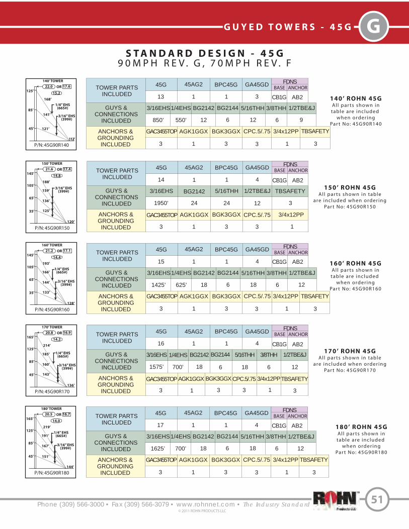
TOWER PARTS
INCLUDED
GUYS &
CONNECTIONS
INCLUDED
ANCHORS &
GROUNDING
INCLUDED
45G 45AG2 BPC45G GA45GD
3/16EHS BG2142 5/16THH 1/2TBE&J
TBSAFETYAGK1GGX BGK3GGX CPC.5/.75
16 1 1 4
1575’ 18 18 12
33 31 3
3/4x12PP
1
FDNS
BASE ANCHOR
AB2CB1G
GAC3455TOP
BG2144
6
1/4EHS
700’
3/8THH
6
Phone (309) 566-3000 • Fax (309) 566-3079 • www.rohnnet.com • The Industry Standard
GG U Y E D T O W E R S - 4 5 G
S T A N D A R D D E S I G N - 4 5 G
9 0 M P H R E V . G , 7 0 M P H R E V . F
51© 2011 ROHN PRODUCTS LLC
P/N: 45G90R140
140’ TOWER
125’
22.0 17.6
15.2
OR
168’
112’
1/4” EHS(665#)
141’
85’
45’ 121’
TOWER PARTS
INCLUDED
GUYS &
CONNECTIONS
INCLUDED
ANCHORS &
GROUNDING
INCLUDED
45G 45AG2 BPC45G GA45GD
3/16EHS1/4EHS BG2142 BG2144 5/16THH
GAC3455TOP AGK1GGX BGK3GGX CPC.5/.75
13 1 1 3
850’ 550’ 12 6 12
3 31 3
140’ ROHN 45G
Al l par ts shown in
table are inc luded
when order ing
Par t No: 45G90R140
3/4x12PP
1
FDNS
BASE ANCHOR
3/8THH
6
1/2TBE&J
93/16” EHS
(399#)
P/N: 45G90R160
160’ TOWER
145’
21.2 17.1
14.4
OR
193’
128’
1/4” EHS(665#)166’
105’
35’ 133’
65’144’ 3/16” EHS
(399#)
TOWER PARTS
INCLUDED
GUYS &
CONNECTIONS
INCLUDED
ANCHORS &
GROUNDING
INCLUDED
45G 45AG2 BPC45G GA45GD
GAC3455TOP AGK1GGX BGK3GGX CPC.5/.75
15 1 1 4
1425’ 625’ 18 6 18
3 31 3
3/4x12PP
1
FDNS
BASE ANCHOR
6 12
160’ ROHN 45G
Al l par ts shown in
table are inc luded
when order ing
Par t No: 45G90R160
3/16EHS1/4EHS BG2142 BG2144 5/16THH 3/8THH 1/2TBE&J
P/N: 45G90R180
180’ TOWER
165’
20.5 16.7
14.0
OR
219’
144’
1/4” EHS(665#)191’
125’
45’ 151’
85’167’ 3/16” EHS
(399#)
TOWER PARTS
INCLUDED
GUYS &
CONNECTIONS
INCLUDED
ANCHORS &
GROUNDING
INCLUDED
45G 45AG2 BPC45G GA45GD
GAC3455TOP AGK1GGX BGK3GGX CPC.5/.75
17 1 1 4
1625’ 700’ 18 6 18
3 31 3
3/4x12PP
1
FDNS
BASE ANCHOR
6 12
180’ ROHN 45G
Al l par ts shown in
table are inc luded
when order ing
Par t No: 45G90R180
3/16EHS1/4EHS BG2142 BG2144 5/16THH 3/8THH 1/2TBE&J
P/N: 45G90R150
150’ TOWER
145’
21.6 17.4
14.8
OR
188’
120’
159’
105’
35’ 125’
65’136’
3/16” EHS(399#)
TOWER PARTS
INCLUDED
GUYS &
CONNECTIONS
INCLUDED
ANCHORS &
GROUNDING
INCLUDED
45G 45AG2 BPC45G GA45GD
3/16EHS BG2142 5/16THH 1/2TBE&J TBSAFETY
GAC3455TOP AGK1GGX BGK3GGX CPC.5/.75
14 1 1 4
1950’ 24 24 12 3
3 31 3
150’ ROHN 45G
Al l par ts shown in table
are included when order ing
Par t No: 45G90R150
3/4x12PP
1
FDNS
BASE ANCHOR
P/N: 45G90R170
170’ TOWER
165’
20.8 16.9
14.2
OR
214’
136’
185’
125’
45’ 143’
85’160’ 3/16” EHS
(399#)
170’ ROHN 45G
Al l par ts shown in table
are included when order ing
Par t No: 45G90R170
1/4” EHS(665#)
AB2
AB2
AB2
AB2
CB1G
CB1G
CB1G
CB1G
TBSAFETY
3
TBSAFETY
3
TBSAFETY
3

Phone (309) 566-3000 • Fax (309) 566-3079 • www.rohnnet.com • The Industry Standard
G G U Y E D T O W E R S - 4 5 G
S T A N D A R D D E S I G N - 4 5 G
9 0 M P H R E V . G , 7 0 M P H R E V . F
52© 2011 ROHN PRODUCTS LLC
P/N: 45G90R200
200’ TOWER
185’19.8 16.3
11.4
OR
245’
160’
1/4” EHS(665#)216’
145’
35’
105’
191’ 3/16” EHS(399#)
TOWER PARTS
INCLUDED
GUYS &
CONNECTIONS
INCLUDED
ANCHORS &
GROUNDING
INCLUDED
45G BPC45G APL45G
AGK1GGX BGK3GGX CPC.5/.75
20 1 1
2375’ 800’ 24 6 24
3 31 3
3/4x12PP
1
FDNS
BASE ANCHOR
6 15
200’ ROHN 45G
Al l par ts shown intable are inc luded
when order ingPar t No: 45G90R200
3/16EHS1/4EHS BG2142 BG2144 5/16THH 3/8THH 1/2TBE&J
GA45GD
5
173’
164’
65’
P/N: 45G90R220
220’ TOWER
205’19.3 16.0
11.0
OR
270’
176’
1/4” EHS(665#)241’
165’
45’
125’
216’
TOWER PARTS
INCLUDED
GUYS &
CONNECTIONS
INCLUDED
ANCHORS &
GROUNDING
INCLUDED
45G BPC45G APL45G
GAC3455TOP AGK1GGX BGK3GGX CPC.5/.75
22 1 1
2100’ 875’ 24 6 24
6 62 3
3/4x12PP
1
6 15
220’ ROHN 45G
Al l par ts shown intable are inc luded
when order ingPar t No: 45G90R220
3/16EHS1/4EHS BG2142 BG2144 5/16THH 3/8THH 1/2TBE&J
GA45GD
5
85’
87’
113’
3/16” EHS(399#)
6
TBSAFETY
75’
P/N: 45G90R190
190’ TOWER
185’20.2 16.5
13.6
OR
239’
152’
210’
145’
35’
105’
185’
3/16” EHS(399#)
165’
156’
65’
TOWER PARTS
INCLUDED
GUYS &
CONNECTIONS
INCLUDED
ANCHORS &
GROUNDING
INCLUDED
45G 45AG2 BPC45G GA45GD
3/16EHS BG2142 5/16THH 1/2TBE&J TBSAFETY
GAC3455TOP AGK1GGX BGK3GGX CPC.5/.75
18 1 1 5
3050’ 30 30 15 3
3 31 3
190’ ROHN 45G
Al l par ts shown in tableare included when order ing
Par t No: 45G90R190
3/4x12PP
1
FDNS
BASE ANCHOR
P/N: 45G90R210
210’ TOWER
205’19.5 16.1
11.2
OR
265’
168’
235’
165’
45’
85’
87’
113’
3/16” EHS(399#)209’
125’
75’
TOWER PARTS
INCLUDED
GUYS &
CONNECTIONS
INCLUDED
ANCHORS &
GROUNDING
INCLUDED
45G APL45G BPC45G GA45GD
3/16EHS BG2142 5/16THH 1/2TBE&J TBSAFETY
GAC3455TOP AGK1GGX BGK3GGX CPC.5/.75
21 1 1 5
2900’ 30 30 15 6
6 62 3
210’ ROHN 45G
Al l par ts shown in tableare included when order ing
Par t No: 45G90R2103/4x12PP
1
TOWER PARTS
INCLUDED
GUYS &
CONNECTIONS
INCLUDED
ANCHORS &
GROUNDING
INCLUDED
45G APL45G BPC45G GA45GD
3/16EHS BG2142 5/16THH TBSAFETY
GAC3455TOP AGK1GGX BGK3GGX CPC.5/.75
23 1 1 6
3675’ 36 36 6
6 62 3
230’ ROHN 45G
Al l par ts shown in tableare included when order ing
Par t No: 45G90R2303/4x12PP
1P/N: 45G90R230
230’ TOWER
225’19.1 15.8
10.6
OR
291’
184’
261’
185’
35’
105’
65’
65’
85’
3/16” EHS(399#)
234’
212’
145’
55’
1/2TBE&J
18
AB2
AB2
BASE INNERANCHOR
OUTERANCHOR
AB2AB2
BASE INNERANCHOR
OUTERANCHOR
AB2AB1
BASE INNERANCHOR
OUTERANCHOR
AB2AB1
GAC3455TOP
CB1G
CB1G
CB2G
CB2G
CB2G
TBSAFETY
3

TOWER PARTS
INCLUDED
GUYS &
CONNECTIONS
INCLUDED
ANCHORS &
GROUNDING
INCLUDED
45G BPC45G APL45G
AGK1GGX BGK3GGX CPC.5/.75
26 1 1
3200’ 1025’ 30 6 30
62 3
3/4x12PP
1
6 18
3/16EHS1/4EHS BG2142 BG2144 5/16THH 3/8THH 1/2TBE&J
GA45GD
6
6
TBSAFETY
6
BASE INNERANCHOR
CB3G
OUTERANCHOR
AB2AB2
GAC3455TOP
TOWER PARTS
INCLUDED
GUYS &
CONNECTIONS
INCLUDED
ANCHORS &
GROUNDING
INCLUDED
45G BPC45G APL45G
AGK1GGX BGK3GGX CPC.5/.75
25 1 1
3125’ 1025’ 30 6 30
62 3
3/4x12PP
1
6 18
3/16EHS1/4EHS BG2142 BG2144 5/16THH 3/8THH 1/2TBE&J
GA45GD
6
6
TBSAFETY
6
BASE INNERANCHOR
CB2G
OUTERANCHOR
AB2AB1
GAC3455TOP
Phone (309) 566-3000 • Fax (309) 566-3079 • www.rohnnet.com • The Industry Standard
GG U Y E D T O W E R S - 4 5 G
S T A N D A R D D E S I G N - 4 5 G
9 0 M P H R E V . G , 7 0 M P H R E V . F
53© 2011 ROHN PRODUCTS LLC
240’ ROHN 45G
Al l par ts shown intable are inc luded
when order ingPar t No: 45G90R240
P/N: 45G90R240
240’ TOWER
225’18.9 15.7
10.4
OR
296’
192’
1/4” EHS(665#)267’
185’
35’
105’
65’
65’
85’
3/16” EHS(399#)
241’
219’
145’
55’
P/N: 45G90R260
260’ TOWER
245’18.4 15.5
10.2
OR
321’
208’
1/4” EHS(665#)292’
205’
45’
125’
260’ ROHN 45G
Al l par ts shown intable are inc luded
when order ingPar t No: 45G90R260
85’
87’
113’
3/16” EHS(399#)
265’
243’
165’
75’
P/N: 45G90R280
280’ TOWER
265’18.0 15.2
9.8
OR
347’
224’
1/4” EHS(665#)317’
225’
65’
145’
280’ ROHN 45G
Al l par ts shown intable are inc luded
when order ingPar t No: 45G90R280
105’
111’
138’
3/16” EHS(399#)
291’
267’
185’
90’
35’97’
250’ ROHN 45G
Al l par ts shown intable are inc luded
when order ingPar t No: 45G90R250
P/N: 45G90R250
250’ TOWER
245’18.6 15.6
10.4
OR
316’
200’
1/4” EHS(665#)286’
205’
45’
125’
85’
87’
113’
3/16” EHS(399#)
259’
236’
165’
75’
P/N: 45G90R270
270’ TOWER
265’18.2 15.4
10.0
OR
342’
216’
1/4” EHS(665#)312’
225’
65’
145’
270’ ROHN 45G
Al l par ts shown intable are inc luded
when order ingPar t No: 45G90R270
105’
111’
138’
3/16” EHS(399#)
284’
260’
185’
90’
35’97’
TOWER PARTS
INCLUDED
GUYS &
CONNECTIONS
INCLUDED
ANCHORS &
GROUNDING
INCLUDED
45G BPC45G APL45G
AGK1GGX BGK3GGX CPC.5/.75
24 1 1
2800’ 950’ 30 6 30
62 3
3/4x12PP
1
6 18
3/16EHS1/4EHS BG2142 BG2144 5/16THH 3/8THH 1/2TBE&J
GA45GD
6
6
TBSAFETY
6
BASE INNERANCHOR
CB2G
OUTERANCHOR
AB2AB1
GAC3455TOP
TOWER PARTS
INCLUDED
GUYS &
CONNECTIONS
INCLUDED
ANCHORS &
GROUNDING
INCLUDED
45G BPC45G APL45G
AGK1GGX BGK3GGX CPC.5/.75
27 1 1
3825’ 1100’ 36 6 36
62 3
3/4x12PP
1
6 21
3/16EHS1/4EHS BG2142 BG2144 5/16THH 3/8THH 1/2TBE&J
GA45GD
7
6
TBSAFETY
6
BASE INNERANCHOR
CB3G
OUTERANCHOR
AB2AB2
GAC3455TOP
TOWER PARTS
INCLUDED
GUYS &
CONNECTIONS
INCLUDED
ANCHORS &
GROUNDING
INCLUDED
45G BPC45G APL45G
AGK1GGX BGK3GGX CPC.5/.75
28 1 1
3900’ 1125’ 36 6 36
62 3
3/4x12PP
1
6 21
3/16EHS1/4EHS BG2142 BG2144 5/16THH 3/8THH 1/2TBE&J
GA45GD
7
6
TBSAFETY
6
BASE INNERANCHOR
CB3G
OUTERANCHOR
AB2AB2
GAC3455TOP

Phone (309) 566-3000 • Fax (309) 566-3079 • www.rohnnet.com • The Industry Standard
G G U Y E D T O W E R S - 4 5 G
S T A N D A R D D E S I G N - 4 5 G
9 0 M P H R E V . G , 7 0 M P H R E V . F
54© 2011 ROHN PRODUCTS LLC
P/N: 45G90R300
300’ TOWER
285’17.6 15.0
9.6
OR
373’
240’
1/4” EHS(665#)343’
245’
85’
165’
300’ ROHN 45G
Al l par ts shown intable are inc luded
when order ingPar t No: 45G90R300
125’
135’
163’
3/16” EHS(399#)
316’
291’
205’
105’
45’
114’
P/N: 45G90R290
290’ TOWER
285’17.8 15.1
9.6
OR
367’
232’
1/4” EHS(665#)337’
245’
85’
165’
290’ ROHN 45G
Al l par ts shown intable are inc luded
when order ingPar t No: 45G90R290
125’
135’
163’
3/16” EHS(399#)
310’
285’
205’
105’
45’
114’
TOWER PARTS
INCLUDED
GUYS &
CONNECTIONS
INCLUDED
ANCHORS &
GROUNDING
INCLUDED
45G BPC45G APL45G
AGK1GGX BGK3GGX CPC.5/.75
29 1 1
4275’ 1175’ 36 6 36
62 3
3/4x12PP
1
6 21
3/16EHS1/4EHS BG2142 BG2144 5/16THH 3/8THH 1/2TBE&J
GA45GD
7
6
TBSAFETY
6
BASE INNERANCHOR
CB3G
OUTERANCHOR
AB2AB2
GAC3455TOP
TOWER PARTS
INCLUDED
GUYS &
CONNECTIONS
INCLUDED
ANCHORS &
GROUNDING
INCLUDED
45G BPC45G APL45G
AGK1GGX BGK3GGX CPC.5/.75
30 1 1
4350’ 1200’ 36 6 36
62 3
3/4x12PP
1
6 21
3/16EHS1/4EHS BG2142 BG2144 5/16THH 3/8THH 1/2TBE&J
GA45GD
7
6
TBSAFETY
6
BASE INNERANCHOR
CB3G
OUTERANCHOR
AB2AB2
GAC3455TOP

S T A N D A R D D E S I G N - 4 5 G
1 1 0 M P H R E V . G , 9 0 M P H R E V . F
Phone (309) 566-3000 • Fax (309) 566-3079 • www.rohnnet.com • The Industry Standard
GG U Y E D T O W E R S - 4 5 G
55© 2011 ROHN PRODUCTS LLC
P/N: 45G110R040
40’ TOWER
31’
21.3 15.5
21.6
OR
45’
32’
1/4” EHS(665#)
TOWER PARTS
INCLUDED
GUYS &
CONNECTIONS
INCLUDED
ANCHORS &
GROUNDING
INCLUDED
45G 45AG2 BPC45G GA45GD
1/4EHS BG2144
GAC3455TOP AGK1GGX BGK3GGX CPC.5/.75
3 1 1 1
150’ 6 3
3 31 3
40’ ROHN 45G
Al l par ts shown in
table are inc luded
when order ing
Par t No: 45G110R040
3/4x12PP
1
FDNS
BASE ANCHOR
3/8THH
6
TBSAFETY
3
1/2TBE&J
P/N: 45G110R060
60’ TOWER
51’
18.9 14.1
19.0
OR
70’
48’
1/4” EHS(665#)54’
25’
3/16” EHS(399#)
TOWER PARTS
INCLUDED
GUYS &
CONNECTIONS
INCLUDED
ANCHORS &
GROUNDING
INCLUDED
45G 45AG2 BPC45G GA45GD
GAC3455TOP AGK1GGX BGK3GGX CPC.5/.75
5 1 1 2
175’ 225’ 6 6 6
3 31 3
3/4x12PP
1
FDNS
BASE ANCHOR
6 6
60’ ROHN 45G
Al l par ts shown in
table are inc luded
when order ing
Par t No: 45G110R060
3/16EHS1/4EHS BG2142 BG2144 5/16THH 3/8THH 1/2TBE&J
TBSAFETY
3
P/N: 45G110R080
80’ TOWER
71’
17.4 13.4
17.4
OR
96’
64’
1/4” EHS(665#)73’
35’
3/16” EHS(399#)
TOWER PARTS
INCLUDED
GUYS &
CONNECTIONS
INCLUDED
ANCHORS &
GROUNDING
INCLUDED
45G 45AG2 BPC45G GA45GD
GAC3455TOP AGK1GGX BGK3GGX CPC.5/.75
7 1 1 2
250’ 325’ 6 6 6
3 31 3
3/4x12PP
1
FDNS
BASE ANCHOR
6 6
80’ ROHN 45G
Al l par ts shown in
table are inc luded
when order ing
Par t No: 45G110R080
3/16EHS1/4EHS BG2142 BG2144 5/16THH 3/8THH 1/2TBE&J
TBSAFETY
3
P/N: 45G110R050
50’ TOWER
41’
19.9 14.7
20.2
OR
57’
40’
1/4” EHS(665#)
TOWER PARTS
INCLUDED
GUYS &
CONNECTIONS
INCLUDED
ANCHORS &
GROUNDING
INCLUDED
45G 45AG2 BPC45G GA45GD
1/4EHS BG2144
GAC3455TOP AGK1GGX BGK3GGX CPC.5/.75
4 1 1 1
200’ 6 3
3 31 3
50’ ROHN 45G
Al l par ts shown in
table are inc luded
when order ing
Par t No: 45G110R050
3/4x12PP
1
FDNS
BASE ANCHOR
3/8THH
6
TBSAFETY
3
1/2TBE&J
P/N: 45G110R070
70’ TOWER
61’
18.0 13.7
18.2
OR
83’
56’
1/4” EHS(665#)63’
29’
3/16” EHS(399#)
TOWER PARTS
INCLUDED
GUYS &
CONNECTIONS
INCLUDED
ANCHORS &
GROUNDING
INCLUDED
45G 45AG2 BPC45G GA45GD
GAC3455TOP AGK1GGX BGK3GGX CPC.5/.75
6 1 1 2
225’ 275’ 6 6 6
3 31 3
3/4x12PP
1
FDNS
BASE ANCHOR
6 6
70’ ROHN 45G
Al l par ts shown in
table are inc luded
when order ing
Par t No: 45G110R070
3/16EHS1/4EHS BG2142 BG2144 5/16THH 3/8THH 1/2TBE&J
TBSAFETY
3
CB1G AB2
CB1G AB2
CB1G AB2
CB1G AB2
CB1G AB2

TOWER PARTS
INCLUDED
GUYS &
CONNECTIONS
INCLUDED
ANCHORS &
GROUNDING
INCLUDED
45G 45AG2 BPC45G GA45GD
GAC3455TOP AGK1GGX BGK3GGX CPC.5/.75
8 1 1 2
275’ 350’ 6 6 6
3 31 3
3/4x12PP
1
FDNS
BASE ANCHOR
6 6
3/16EHS1/4EHS BG2142 BG2144 5/16THH 3/8THH 1/2TBE&J
TBSAFETY
3
CB1G AB2
Phone (309) 566-3000 • Fax (309) 566-3079 • www.rohnnet.com • The Industry Standard
G G U Y E D T O W E R S - 4 5 G
S T A N D A R D D E S I G N - 4 5 G
1 1 0 M P H R E V . G , 9 0 M P H R E V . F
56© 2011 ROHN PRODUCTS LLC
P/N: 45G110R100
100’ TOWER
91’
16.3 12.7
16.2
OR
121’
80’
1/4” EHS(665#)101’
61’
3/16” EHS(399#)
100’ ROHN 45G
Al l par ts shown in
table are inc luded
when order ing
Par t No: 45G110R100
31’86’
P/N: 45G110R120
120’ TOWER
111’
15.4 12.2
15.2
OR
147’
96’
1/4” EHS(665#)122’
75’
3/16” EHS(399#)
TOWER PARTS
INCLUDED
GUYS &
CONNECTIONS
INCLUDED
ANCHORS &
GROUNDING
INCLUDED
45G 45AG2 BPC45G GA45GD
GAC3455TOP AGK1GGX BGK3GGX CPC.5/.75
11 1 1 3
725’ 475’ 12 6 12
3 31 3
3/4x12PP
1
FDNS
BASE ANCHOR
6 9
3
120’ ROHN 45G
Al l par ts shown in
table are inc luded
when order ing
Par t No: 45G110R120
3/16EHS1/4EHS BG2142 BG2144 5/16THH 3/8THH
TBSAFETY
1/2TBE&J35’
102’
P/N: 45G110R110
110’ TOWER
101’
15.8 12.5
15.6
OR
134’
88’
1/4” EHS(665#)111’
67’
3/16” EHS(399#)
TOWER PARTS
INCLUDED
GUYS &
CONNECTIONS
INCLUDED
ANCHORS &
GROUNDING
INCLUDED
45G 45AG2 BPC45G GA45GD
GAC3455TOP AGK1GGX BGK3GGX CPC.5/.75
10 1 1 3
675’ 450’ 12 6 12
3 31 3
3/4x12PP
1
FDNS
BASE ANCHOR
6 9
110’ ROHN 45G
Al l par ts shown in
table are inc luded
when order ing
Par t No: 45G110R110
3/16EHS1/4EHS BG2142 BG2144 5/16THH 3/8THH 1/2TBE&J
TBSAFETY
3
34’94’
P/N: 45G110R130
130’ TOWER
121’
15.1 12.0
14.8
OR
160’
104’
1/4” EHS(665#)130’
78’
3/16” EHS(399#)
TOWER PARTS
INCLUDED
GUYS &
CONNECTIONS
INCLUDED
ANCHORS &
GROUNDING
INCLUDED
45G 45AG2 BPC45G GA45GD
GAC3455TOP AGK1GGX BGK3GGX CPC.5/.75
12 1 1 3
775’ 525’ 12 6 12
3 31 3
3/4x12PP
1
FDNS
BASE ANCHOR
6 9
3
130’ ROHN 45G
Al l par ts shown in
table are inc luded
when order ing
Par t No: 45G110R130
3/16EHS1/4EHS BG2142 BG2144 5/16THH 3/8THH
TBSAFETY
1/2TBE&J35’
110’
TOWER PARTS
INCLUDED
GUYS &
CONNECTIONS
INCLUDED
ANCHORS &
GROUNDING
INCLUDED
45G 45AG2 BPC45G GA45GD
GAC3455TOP AGK1GGX BGK3GGX CPC.5/.75
9 1 1 3
600’ 400’ 12 6 12
3 31 3
3/4x12PP
1
FDNS
BASE ANCHOR
6 9
3/16EHS1/4EHS BG2142 BG2144 5/16THH 3/8THH 1/2TBE&J
TBSAFETY
3
CB1G AB2
CB1G AB2
CB1G AB2
CB1G AB2
P/N: 45G110R090
90’ TOWER
81’
16.8 13.0
16.8
OR
108’
72’
82’
39’
3/16” EHS(399#)
90’ ROHN 45G
Al l par ts shown in
table are inc luded
when order ing
Par t No: 45G110R090
1/4” EHS(665#)

Phone (309) 566-3000 • Fax (309) 566-3079 • www.rohnnet.com • The Industry Standard
GG U Y E D T O W E R S - 4 5 G
S T A N D A R D D E S I G N - 4 5 G
1 1 0 M P H R E V . G , 9 0 M P H R E V . F
57© 2011 ROHN PRODUCTS LLC
P/N: 45G110R150
150’ TOWER
141’
14.5 11.7
14.0
OR
185’
120’
1/4” EHS(665#)160’
106’
3/16” EHS(399#)
TOWER PARTS
INCLUDED
GUYS &
CONNECTIONS
INCLUDED
ANCHORS &
GROUNDING
INCLUDED
45G 45AG2 BPC45G GA45GD
GAC3455TOP AGK1GGX BGK3GGX CPC.5/.75
14 1 1 4
1375’ 600’ 18 6 18
3 31 3
3/4x12PP
1
FDNS
BASE ANCHOR
6 12
3
150’ ROHN 45G
Al l par ts shown in
table are inc luded
when order ing
Par t No: 45G110R150
3/16EHS1/4EHS BG2142 BG2144 5/16THH 3/8THH
TBSAFETY
1/2TBE&J72’
140’
125’35’
P/N: 45G110R160
160’ TOWER
151’
14.2 11.5
13.8
OR
198’
128’
1/4” EHS(665#)171’
113’
3/16” EHS(399#)
TOWER PARTS
INCLUDED
GUYS &
CONNECTIONS
INCLUDED
ANCHORS &
GROUNDING
INCLUDED
45G 45AG2 BPC45G GA45GD
GAC3455TOP AGK1GGX BGK3GGX CPC.5/.75
15 1 1 4
1450’ 650’ 18 6 18
3 31 3
3/4x12PP
1
FDNS
BASE ANCHOR
6 12
3
160’ ROHN 45G
Al l par ts shown in
table are inc luded
when order ing
Par t No: 45G110R160
3/16EHS1/4EHS BG2142 BG2144 5/16THH 3/8THH
TBSAFETY
1/2TBE&J76’
149’
134’38’
P/N: 45G110R170
170’ TOWER
161’
14.0 11.4
13.6
OR
211’
136’
1/4” EHS(605#)
187’
128’
3/16” EHS(399#)
TOWER PARTS
INCLUDED
GUYS &
CONNECTIONS
INCLUDED
ANCHORS &
GROUNDING
INCLUDED
45G 45AG2 BPC45G GA45GD
GAC5655TOP AGK1GGX BGK3GGX CPC1/1.25
16 1 1 5
2050’ 675’ 24 6 24
3 31 3
3/4x12PP
1
FDNS
BASE ANCHOR
6 15
170’ ROHN 45G
Al l par ts shown in
table are inc luded
when order ing
Par t No: 45G110R1703/16EHS 1/4EHS BG2142BG2144 5/16THH 3/8THH 5/8TBE&J
64’150’
32’
96’166’
TBSAFETY
3
140’
P/N: 45G110R180
180’ TOWER
172’
13.8 11.2
13.2
OR
224’
144’
5/16” EHS(1,120#)
197’
135’
3/16” EHS(399#)
TOWER PARTS
INCLUDED
GUYS &
CONNECTIONS
INCLUDED
ANCHORS &
GROUNDING
INCLUDED
45G 45GL2* BPC45G GA45GD
GAC5655TOP AGK1GGX BGK3GGX CPC1/1.25
17 1 1 5
2175’ 725’ 24 6 24
3 31 3
3/4x12PP
1
FDNS
BASE ANCHOR
6 15
180’ ROHN 45G
All parts shown in
table are included
when ordering
Part No: 45G110R180
3/16EHS 142265 BG2142BG2146 5/16THH 7/16THH 5/8TBE&J
66’158’
33’
99’175’
TBSAFETY
3
148’
CB1G AB2
CB2G AB2
CB2G AB3
CB2G AB3
P/N: 45G110R140
140’ TOWER
131’
14.8 11.8
14.4
OR
172’
112’
1/4” EHS(665#)149’
98’
3/16” EHS(399#)
TOWER PARTS
INCLUDED
GUYS &
CONNECTIONS
INCLUDED
ANCHORS &
GROUNDING
INCLUDED
45G 45AG2 BPC45G GA45GD
GAC3455TOP AGK1GGX BGK3GGX CPC.5/.75
13 1 1 4
1275’ 550’ 18 6 18
3 31 3
3/4x12PP
1
FDNS
BASE ANCHOR
6 12
3
140’ ROHN 45G
Al l par ts shown in
table are inc luded
when order ing
Par t No: 45G110R140
3/16EHS1/4EHS BG2142 BG2144 5/16THH 3/8THH
TBSAFETY
1/2TBE&J65’
129’
116’32’
CB1G AB2
APL45G
1
* 45GL2 Lug section required for 5/16” guy

Phone (309) 566-3000 • Fax (309) 566-3079 • www.rohnnet.com • The Industry Standard
G G U Y E D T O W E R S - 4 5 G
S T A N D A R D D E S I G N - 4 5 G
1 1 0 M P H R E V . G , 9 0 M P H R E V . F
58© 2011 ROHN PRODUCTS LLC
P/N: 45G110R200
200’ TOWER
192’
13.4 11.0
10.6
OR
250’
160’
5/16” EHS(1,120#)
223’
155’
3/16” EHS(399#)
200’ ROHN 45G
All parts shown intable are included
when orderingPart No: 45G110R200
75’177’
35’
115’197’
164’
P/N: 45G110R220
220’ TOWER
212’13.0 10.8
10.2
OR
276’
176’
5/16” EHS(1,120#)
175’
35’
139’
105’
69’
91’
3/16” EHS(399#)
60’
69’205’
224’
248’
1/4” EHS(665#)
210’ ROHN 45G
All parts shown intable are included
when orderingPart No: 45G110R210
P/N: 45G110R210
210’ TOWER
202’13.2 10.9
10.4
OR
263’
168’
5/16” EHS(1,120#)
167’
33’
133’
99’
64’
85’
3/16” EHS(399#)
55’
65’195’
214’
237’
220’ ROHN 45G
All parts shown intable are included
when orderingPart No: 45G110R220
P/N: 45G110R190
190’ TOWER
182’
13.6 11.1
13.0
OR
237’
152’
5/16” EHS(1,120#)
210’
145’
3/16” EHS(399#)
190’ ROHN 45G
All parts shown intable are included
when orderingPart No: 45G110R190
73’169’
36’
109’187’
156’
TOWER PARTS
INCLUDED
GUYS &
CONNECTIONS
INCLUDED
ANCHORS &
GROUNDING
INCLUDED
45G 45GL2* BPC45G GA45GD
GAC5655TOP AGK1GGX BGK3GGX CPC1/1.25
18 1 1 5
2300’ 725’ 24 6 24
3 31 3
3/4x12PP
1
FDNS
BASE ANCHOR
6 15
3/16EHS 142265 BG2142BG2146 5/16THH 7/16THH 5/8TBE&J
TBSAFETY
3
CB2G AB3
APL45G
1
TOWER PARTS
INCLUDED
GUYS &
CONNECTIONS
INCLUDED
ANCHORS &
GROUNDING
INCLUDED
45G 45GL2* BPC45G GA45GD
GAC5655TOP AGK1GGX BGK3GGX CPC1/1.25
19 1 1 5
2425’ 800’ 24 6 24
3 31 3
3/4x12PP
1
FDNS
BASE ANCHOR
6 15
3/16EHS 142265 BG2142BG2146 5/16THH 7/16THH 5/8TBE&J
TBSAFETY
3
CB2G AB3
APL45G
1
TOWER PARTS
INCLUDED
GUYS &
CONNECTIONS
INCLUDED
ANCHORS &
GROUNDING
INCLUDED
45G BPC45G APL45G GA45GD
GAC3455TOP BGK3GGX CPC.5/.75
20 1 1 6
33 3
CPC1/1.25
3
3/16EHS
2550’
7/16THH
6
142265
850’
BG2142
30
1/2TBE&J
6
BG2146
6
5/8TBE&J
12
5/16THH
30
TBSAFETY
6
AGK1GGX
2
GAC5655TOP
3
BASE INNERANCHOR
CB3G
OUTERANCHOR
AB3AB2
45GL2*
1
3/4x12PP
1
TOWER PARTS
INCLUDED
GUYS &
CONNECTIONS
INCLUDED
ANCHORS &
GROUNDING
INCLUDED
45G BPC45G APL45G GA45GD
GAC3455TOP BGK3GGX CPC.5/.75
21 1 1 6
33 3
CPC1/1.25
3
3/16EHS
1875’
1/4EHS
800’
142265
900’
5/16THH
24
BG2142
24
3/8THH
6
BG2144
6
7/16THH
6
AGK1GGX
2
GAC5655TOP
3
BASE INNERANCHOR
CB3G
OUTERANCHOR
AB3AB2
45GL2*
1
5/8TBE&J
12
BG2146
6
1/2TBE&J
6
TBSAFETY
6
3/4X12PP
1
* 45GL2 Lug section required for 5/16” guy

TOWER PARTS
INCLUDED
GUYS &
CONNECTIONS
INCLUDED
ANCHORS &
GROUNDING
INCLUDED
45G BPC45G APL45G GA45GD
GAC3455TOP BGK3GGX CPC.5/.75
23 1 1 7
33 3
CPC1/1.25
3
3/16EHS
2525’
BG2146
6
1/4EHS
875’
5/16THH
30
142265
975’
3/8THH
6
BG2142
30
7/16THH
6
BG2144
6
AGK1GGX
23
1/2TBE&J
9
5/8TBE&J
12
TBSAFETY
6
BASE INNERANCHOR
CB3G
OUTERANCHOR
AB3AB2
3/4x12PP
1
45GL2*
1
GAC5655TOP
S T A N D A R D D E S I G N - 4 5 G
1 1 0 M P H R E V . G , 9 0 M P H R E V . F
Phone (309) 566-3000 • Fax (309) 566-3079 • www.rohnnet.com • The Industry Standard
GG U Y E D T O W E R S - 4 5 G
59© 2011 ROHN PRODUCTS LLC
240’ ROHN 45G
All parts shown intable are included
when orderingPart No: 45G110R240
P/N: 45G110R240
240’ TOWER
232’12.7 10.6
10.0
OR
301’
192’
5/16” EHS(1,120#)
195’
35’
159’
125’
87’
3/16” EHS(399#)
80’
65’
229’
249’
274’
1/4” EHS(665#)
103’
124’
95’
P/N: 45G110R230
230’ TOWER
222’12.8 10.7
10.0
OR
288’
184’
5/16” EHS(1,120#)
185’
33’
155’
125’
87’
3/16” EHS(399#)
80’
65’
222’
241’
261’
1/4” EHS(665#)
103’
124’
95’
230’ ROHN 45G
All parts shown intable are included
when orderingPart No: 45G110R230
TOWER PARTS
INCLUDED
GUYS &
CONNECTIONS
INCLUDED
ANCHORS &
GROUNDING
INCLUDED
45G BPC45G APL45G GA45GD
GAC3455TOP BGK3GGX CPC.5/.75
22 1 1 7
33 3
CPC1/1.25
3
3/16EHS
2475’
BG2146
6
1/4EHS
850’
5/16THH
30
142265
925’
3/8THH
6
BG2142
30
7/16THH
6
BG2144
6
AGK1GGX
23
1/2TBE&J
9
5/8TBE&J
12
TBSAFETY
6
BASE INNERANCHOR
CB3G
OUTERANCHOR
AB3AB2
3/4x12PP
1
45GL2*
1
GAC5655TOP
* 45GL2 Lug section required for 5/16” guy

Phone (309) 566-3000 • Fax (309) 566-3079 • www.rohnnet.com • The Industry Standard
G G U Y E D T O W E R S - 4 5 G
S T A N D A R D D E S I G N - 4 5 G
1 3 0 M P H R E V . G , 1 1 0 M P H R E V . F
60© 2011 ROHN PRODUCTS LLC
P/N: 45G130R040
40’ TOWER
35’
15.3 11.1
13.0
OR
47’
32’
1/4” EHS(665#)
TOWER PARTS
INCLUDED
GUYS &
CONNECTIONS
INCLUDED
ANCHORS &
GROUNDING
INCLUDED
45G 45AG2 BPC45G GA45GD
1/4EHS BG2144
GAC3455TOP AGK1GGX BGK3GGX CPC.5/.75
3 1 1 1
150’ 6
3 31 3
40’ ROHN 45G
Al l par ts shown in
table are inc luded
when order ing
Par t No: 45G130R040
3/4x12PP
1
FDNS
BASE ANCHOR
3/8THH
6 3
TBSAFETY
3
1/2TBE&J
P/N: 45G130R060
60’ TOWER
55’
13.6 10.2
11.6
OR
73’
48’
1/4” EHS(665#)
25’
54’3/16” EHS
(399#)
TOWER PARTS
INCLUDED
GUYS &
CONNECTIONS
INCLUDED
ANCHORS &
GROUNDING
INCLUDED
45G 45AG2 BPC45G GA45GD
GAC3455TOP AGK1GGX BGK3GGX CPC.5/.75
5 1 1 2
175’ 250’ 6 6 6
3 31 3
3/4x12PP
1
FDNS
BASE ANCHOR
6
3/16EHS1/4EHS BG2142 BG2144 5/16THH 3/8THH
6
1/2TBE&J
TBSAFETY
3
60’ ROHN 45G
Al l par ts shown in
table are inc luded
when order ing
Par t No: 45G130R060
P/N: 45G130R080
80’ TOWER
75’
12.5 9.6
10.6
OR
99’
64’
1/4” EHS(665#)
35’
73’3/16” EHS
(399#)
TOWER PARTS
INCLUDED
GUYS &
CONNECTIONS
INCLUDED
ANCHORS &
GROUNDING
INCLUDED
45G 45AG2 BPC45G GA45GD
GAC3455TOP AGK1GGX BGK3GGX CPC.5/.75
7 1 1 2
250’ 325’ 6 6 6
3 31 3
3/4x12PP
1
FDNS
BASE ANCHOR
6 6
3/16EHS1/4EHS BG2142 BG2144 5/16THH 3/8THH 1/2TBE&J
TBSAFETY
3
80’ ROHN 45G
Al l par ts shown in
table are inc luded
when order ing
Par t No: 45G130R080
P/N: 45G130R050
50’ TOWER
45’
14.3 10.6
12.0
OR
60’
40’
1/4” EHS(665#)
TOWER PARTS
INCLUDED
GUYS &
CONNECTIONS
INCLUDED
ANCHORS &
GROUNDING
INCLUDED
45G 45AG2 BPC45G GA45GD
1/4EHS BG2144
GAC3455TOP AGK1GGX BGK3GGX CPC.5/.75
4 1 1 1
200’ 6
3 31 3
50’ ROHN 45G
Al l par ts shown in
table are inc luded
when order ing
Par t No: 45G130R050
3/4x12PP
1
FDNS
BASE ANCHOR
3/8THH
6 3
TBSAFETY
3
1/2TBE&J
P/N: 45G130R070
70’ TOWER
65’
13.0 9.9
11.0
OR
86’
56’
1/4” EHS(665#)
29’
63’3/16” EHS
(399#)
TOWER PARTS
INCLUDED
GUYS &
CONNECTIONS
INCLUDED
ANCHORS &
GROUNDING
INCLUDED
45G 45AG2 BPC45G GA45GD
GAC3455TOP AGK1GGX BGK3GGX CPC.5/.75
6 1 1 2
225’ 275’ 6 6 6
3 31 3
3/4x12PP
1
FDNS
BASE ANCHOR
6 6
3/16EHS1/4EHS BG2142 BG2144 5/16THH 3/8THH 1/2TBE&J
TBSAFETY
3
70’ ROHN 45G
Al l par ts shown in
table are inc luded
when order ing
Par t No: 45G130R070
CB1G AB2
CB1G AB2
CB1G AB2
CB1G AB2
CB1G AB2

Phone (309) 566-3000 • Fax (309) 566-3079 • www.rohnnet.com • The Industry Standard
GG U Y E D T O W E R S - 4 5 G
S T A N D A R D D E S I G N - 4 5 G
1 3 0 M P H R E V . G , 1 1 0 M P H R E V . F
61© 2011 ROHN PRODUCTS LLC
P/N: 45G130R100
100’ TOWER
95’
11.7 9.2
9.6
OR
124’
80’
1/4” EHS(665#)61’
101’3/16” EHS
(399#)
TOWER PARTS
INCLUDED
GUYS &
CONNECTIONS
INCLUDED
ANCHORS &
GROUNDING
INCLUDED
45G 45AG2 BPC45G GA45GD
GAC3455TOP AGK1GGX BGK3GGX CPC.5/.75
9 1 1 3
600’ 400’ 12 6 12
3 31 3
3/4x12PP
1
FDNS
BASE ANCHOR
6 9
3/16EHS1/4EHS BG2142 BG2144 5/16THH 3/8THH 1/2TBE&J
3
TBSAFETY
100’ ROHN 45G
Al l par ts shown in
table are inc luded
when order ing
Par t No: 45G130R10031’
86’
P/N: 45G130R120
120’ TOWER
115’
11.1 8.8
8.6
OR
150’
96’
5/16”EHS(1,120#)75’
122’3/16” EHS
(399#)
TOWER PARTS
INCLUDED
GUYS &
CONNECTIONS
INCLUDED
ANCHORS &
GROUNDING
INCLUDED
45G 45GL5* BPC45G GA45GD
GAC3455TOP AGK1GGX BGK3GGX CPC.5/.75
11 1 1 3
725’ 500’ 12 6 12
3 31 3
3/4x12PP
1
FDNS
BASE ANCHOR
6 6
3/16EHS 142265 BG2142 BG2146 5/16THH 7/16THH 1/2TBE&J
3
5/8TBE&J
120’ ROHN 45G
All parts shown in
table are included
when ordering
Part No: 45G130R12035’ 102’
TBSAFETY
3
P/N: 45G130R090
90’ TOWER
85’
12.1 9.4
10.0
OR
111’
72’
1/4” EHS(665#)
39’
82’3/16” EHS
(399#)
TOWER PARTS
INCLUDED
GUYS &
CONNECTIONS
INCLUDED
ANCHORS &
GROUNDING
INCLUDED
45G 45AG2 BPC45G GA45GD
GAC3455TOP AGK1GGX BGK3GGX CPC.5/.75
8 1 1 2
275’ 375’ 6 6 6
3 31 3
3/4x12PP
1
FDNS
BASE ANCHOR
6 6
3/16EHS1/4EHS BG2142 BG2144 5/16THH 3/8THH 1/2TBE&J
TBSAFETY
3
90’ ROHN 45G
Al l par ts shown in
table are inc luded
when order ing
Par t No: 45G130R090
P/N: 45G130R110
110’ TOWER
105’
11.4 9.0
9.0
OR
137’
88’
1/4” EHS(665#)67’
111’3/16” EHS
(399#)
TOWER PARTS
INCLUDED
GUYS &
CONNECTIONS
INCLUDED
ANCHORS &
GROUNDING
INCLUDED
45G 45AG2 BPC45G GA45GD
GAC3455TOP AGK1GGX BGK3GGX CPC.5/.75
10 1 1 3
675’ 450’ 12 6 12
3 31 3
3/4x12PP
1
FDNS
BASE ANCHOR
6 9
3/16EHS1/4EHS BG2142 BG2144 5/16THH 3/8THH 1/2TBE&J
3
TBSAFETY
110’ ROHN 45G
Al l par ts shown in
table are inc luded
when order ing
Par t No: 45G130R11034’
94’
P/N: 45G130R130
130’ TOWER
125’
10.9 8.6
8.2
OR
163’
104’
5/16”EHS(1,120#)
78’
130’ 3/16” EHS(399#)
35’ 110’1/4”EHS
(665#)
TOWER PARTS
INCLUDED
GUYS &
CONNECTIONS
INCLUDED
ANCHORS &
GROUNDING
INCLUDED
45G 45GL5* BPC45G GA45GD
GAC5655TOP BGK3GGX CPC1/1.25
12 1 1 3
33 3
3/4x12PP
1
FDNS
BASE ANCHOR
130’ ROHN 45G
All parts shown in
table are included
when ordering
Part No: 45G130R130
3/16EHS
350’
5/16THH
6
1/4EHS
425’
3/8THH
6
142265
525’
7/16THH
6
BG2142
6
BG2144
6
5/8TBE&J
9
BG2146
6
TBSAFETY
3
AGK1GGX
1
CB1G AB2
CB1G AB2
CB1G AB2
CB1G AB2
CB2G AB3
APL45G
1
APL45G
1
* 45GL5 Lug section required for 5/16” guy

Phone (309) 566-3000 • Fax (309) 566-3079 • www.rohnnet.com • The Industry Standard
G G U Y E D T O W E R S - 4 5 G
S T A N D A R D D E S I G N - 4 5 G
1 3 0 M P H R E V . G , 1 1 0 M P H R E V . F
62© 2011 ROHN PRODUCTS LLC
140’ ROHN 45G
Al l par ts shown in
table are inc luded
when order ing
Par t No: 45G130R140
P/N: 45G130R140
140’ TOWER
135’
10.6 8.5
7.8
OR
175’
112’
5/16” EHS(1,120#)149’
98’
32’ 116’
65’129’
3/16” EHS(399#)
1/4” EHS(665#)
P/N: 45G130R140
140’ TOWER
135’
10.6 8.5
7.8
OR
175’
112’
149’
98’
32’ 116’
65’129’
150’ ROHN 45G
Al l par ts shown in
table are inc luded
when order ing
Par t No: 45G130R150
P/N: 45G130R150
150’ TOWER
145’
10.4 8.4
7.4
OR
188’
120’
5/16” EHS(1,120#)160’
106’
35’ 125’
72’140’
3/16” EHS(399#)
1/4” EHS(665#)
TOWER PARTS
INCLUDED
GUYS &
CONNECTIONS
INCLUDED
ANCHORS &
GROUNDING
INCLUDED
45G 45GL5* BPC45G GA45GD
GAC5655TOP BGK3GGX CPC1/1.25
13 1 1 4
33 3
3/4x12PP
1
FDNS
BASE ANCHOR
3/16EHS
800’
5/16THH
12
1/4EHS
475’
3/8THH
6
142265
575’
7/16THH
6
BG2142
12
BG2144
6
5/8TBE&J
12
BG2146
6
TBSAFETY
3
AGK1GGX
1
CB2G AB3
APL45G
1
TOWER PARTS
INCLUDED
GUYS &
CONNECTIONS
INCLUDED
ANCHORS &
GROUNDING
INCLUDED
45G 45GL5* BPC45G GA45GD
GAC5655TOP BGK3GGX CPC1/1.25
14 1 1 4
33 3
3/4x12PP
1
FDNS
BASE ANCHOR
3/16EHS
850’
5/16THH
12
1/4EHS
525’
3/8THH
6
142265
600’
7/16THH
6
BG2142
12
BG2144
6
5/8TBE&J
12
BG2146
6
TBSAFETY
3
AGK1GGX
1
CB2G AB3
APL45G
1
* 45GL5 Lug section required for 5/16” guy

GG U Y E D T O W E R S - 4 5 G
TOP SECTION
45AG2TOP SECTION
45AG3
TOP SECTION
45AG4TOP PLATE HOLE PATTERN IS THE SAME
AS BPL45G.
BEARING PLATE
BPL45GCONVERTS STANDARD SECTION TO A
TOP SECTION. HOLE PATTERN FITSTB3 (2” O.D.) AND TB4 (3” O.D.)
THRUST BEARINGS.
TOP PLATE
APL45GFOR MOUNTING BEACON
OR LIGHTNING ROD.
Phone (309) 566-3000 • Fax (309) 566-3079 • www.rohnnet.com • The Industry Standard
P A R T S & A C C E S S O R I E S
9’ - 0”
7’ - 8”
63
1.66“ O.D.1.38” I.D.1.25” N.P.T. 9’ - 6”
2.38” O.D.2.07“ I.D.
9’ - 0”
2.25” O.D.2.08“ I.D.
8’ - 1“
1’ - 1”2.75” O.D.2.58“ I.D.
TOP SECTION
45AG1
TOP SECTION
45AG5
© 2011 ROHN PRODUCTS LLC
ACCESSORY SHELF
AS455GFOR MOUNTING MANY POPULARROTORS. FIELD DRILLING MAY BE NECESSARY FOR SOME ROTORS.
1’ - 0”
2’ - 0”
8”
1’ - 0”
2’ - 0”
2’ - 0”
1’ - 6”
1’ - 8”
9’ - 0”
2.00“ O.D.1.87” I.D.
TOP SECTION
45AG
1’ - 0”
LIGHTNING ROD
LRCL5’ COPPER CLAD
MOUNTS TO APL45G.
Set Screw
Set Screw
Set Screw
TOP MOUNT
45TDMKD - NO MAST
45TDM2S3KD - 2 3/8” O.D. MAST
45TDM25S3KD - 2 7/8” O.D. MAST
45TDM3S3KD - 3 1/2” O.D. MAST
45TDM35S3KD - 4” O.D. MAST
45TDM4S3KD - 4 1/2” O.D. MAST
MOUNTING TUBE PROVIDED IS 7’ LONG.
1’ - 3 3/4”
2’ - 0”

G G U Y E D T O W E R S - 4 5 G
Phone (309) 566-3000 • Fax (309) 566-3079 • www.rohnnet.com • The Industry Standard
P A R T S & A C C E S S O R I E S
64
* TOWERS MOUNTED ON THESE BASES MUST BE BRACKETED OR GUYED AT ALL TIMES. TEMPORARY STEEL GUYING MAY ALSO BE NECESSARY DURING INSTALLATION AND DISMANTLING.
© 2011 ROHN PRODUCTS LLC
5’ SHORT BASE
SB45G
FOR EMBEDMENT IN CONCRETE.
FLAT ROOF MOUNT
FR45G*BOLTS DIRECTLY TO FLAT ROOF SURFACE.
TAPERED BASE
45TG*CAN BE USED WITH A4197L BASE INSULATOR OR WITH
3/4X12PP, ORDERED SEPARATELY.
CONCRETE BASE PLATE
BPC45G*FOR USE WITH 3/4X12PP PIER PIN
EMBEDDED IN CONCRETE.
CONCRETE BASE PLATE IS TO BEUSED FOR BRACKETED ANDGUYED APPLICATIONS ONLY.
PIER PIN
3/4X12PP
FOR USE WITH BPC45G
EMBEDDED IN CONCRETE.
PIER PIN MUST BE ORDEREDSEPARATELY, UNLESS BEINGPURCHASED AS PART OFA COMPLETE TOWER KIT.
BASE BOLT
5/8X12BBFOR USE WITH BPH45G
(6) REQUIRED, ORDERED SEPARATELY.
SIDE ARM BRACKET
SA253UAMOUNTING TUBE PROVIDED IS 3’ LONG,
2 - 1/4” O.D.
FACE MOUNT
DM45G2 - 2 3/8” O.D. 5’ LONGDM454 - 4 1/2” O.D. 5’ LONG
HEAVY DUTY UNIVERSAL
HOUSE BRACKET
HBUTVROADJUSTABLE TO POSITION TOWER
18” - 36” FROM WALL.
HINGED BASE PLATE
BPH45G*FOR USE WITH 5/8X12BB BASE BOLTS
(ORDERED SEPARATELY).
HINGED TO ALLOW TOWER TO
BE ROTATED UP FROM BASE
DURING INSTALLATION.
HINGED BASE PLATE IS TO BE
USED FOR BRACKETED AND GUYED
APPLICATIONS ONLY.
5/8” x 12”
Adjustable
2.5’ - 3.0’
TORQUE ARM STABILIZER
ASSEMBLY
TA45ANTI-TWIST DEVICE LOCATED IN THE
AREA OF ANTENNAS. PROVIDES SIX-WAYGUYING. BOLTS TO TOWER AT ANY SECTION JOINT. ATTACHED WITH
JOINT BOLTS. MUST BE INSTALLED ASSECTIONS ARE JOINED TOGETHER.
DISH MOUNT
VY4311A2 - 2 3/8” O.D. VY4311A - 4 1/2” O.D.
MAST TUBE PROVIDED IS 5’ LONG.

GG U Y E D T O W E R S - 4 5 G
Phone (309) 566-3000 • Fax (309) 566-3079 • www.rohnnet.com • The Industry Standard
P A R T S & A C C E S S O R I E S
65© 2011 ROHN PRODUCTS LLC
SAFETY RING
SR245SNAPS INTO PLACE AT ANY LEVEL.
NO BOLTS REQUIRED.
WORK PLATFORM
WP45GSNAPS INTO PLACE AT ANY LEVEL.
NO BOLTS REQUIRED.
ERECTION FIXTURE
EF2545 - 2 1/2” SHEAVE WITH 3/8“ I.D. GROOVE.
NOTE: ERECTION FIXTURES ARE FORLIFTING ONE 10’ SECTION AT A TIME ANDARE NOT INTENDED FOR THE LIFTING OF
PERSONNEL.
WARNING WARNING WARNING
THIS ITEM IS NOTINTENDED FOR THELIFTING OF PERSONNEL
See safety precaution literature
THRUSTBEARING
TB3 - SUPPORTS UP TO 2” O.D. MAST.
TB4 - SUPPORTS UP TO 3” O.D. MAST.
MOUNTS TO BPL45G AND 45AG4.
TOWER BUSHING
TB50 - 1-1/4” I.D. X 2” O.D.TB75 - 1-1/2” I.D. X 2” O.D.FOR USE ON 45AG TOP SECTION
GUY BRACKET
GA45GDMOUNTS TO TOWER AT ANY
HORIZONTAL BRACE.
CLIMBING HARNESS
TTFBH-4DJOURNEYMAN HARNESS
TTFBH-C/PPROFESSIONAL HARNESS
SAFETY CABLE SYSTEM
ORDERING INFORMATION
TOWER HEIGHT
50’
100’
150’
200’
250’
300’
350’
PARTNUMBER
TT0504555
TT1004555
TT1504555
TT2004555
TT2504555
TT3004555
TT3504555
SAFETY CABLESLIDER WITH CARABINEER
TT-WG-500-W/SMC
ANTI-CLIMB PANELS
VW913ATHREE ANTI-CLIMB PANELS BOLT TO STANDARD TOWER SECTION.
SAFETY CABLE SLIDER ANDCLIMBING HARNESS MUSTBE ORDERED SEPARATELY.
TORQUE BAR
TB45DOPTIONAL, FOR USE WITH GA45GD.
REQUIRES (1) 3/8” SHACKLE FOR EACH BAR.

Phone (309) 566-3000 • Fax (309) 566-3079 • www.rohnnet.com • The Industry Standard
G G U Y E D T O W E R S - 4 5 G
66© 2011 ROHN PRODUCTS LLC
REV G
ANCHOR GROUNDING
AGK1GGX
REV G
BASE GROUNDING
BGK3GGX
A N C H O R I N F O R M A T I O N
12”
3/8”
2”
3/4”P/N STAMPED HERE
GAC3455TOP
1/2”
12”
120”
1 1/4”P/N STAMPED HERE
GAC5655TOP
2 1/2”
11/16”
13/16”
CL of hole to edgeof plate = 1 1/4”
CL of hole to edgeof plate = 1”
4” x 4” x 3/8” angle
5” x 5” x 3/8” angle
81”
Ground Wire
Ground Rod Clamp
Ground Rod
Clamp
6” Min.
Attach to leg withsupplied leg clamp
Ground Wire
6” Min.Ground Rod Clamp
Ground Rod,3 provided (to be installed
at 120 separation at 20’ spacing.o

All around stirrupsequally spaced 12” O.C. anchored with 90hooks around a horizontal bar
Top and bottom horizontal bars equally spaced
C
B
A
Ground Line
D
Anchor rod
o
Additional bar atcenter-line eachside, when required
GG U Y E D T O W E R S - 4 5 G
Phone (309) 566-3000 • Fax (309) 566-3079 • www.rohnnet.com • The Industry Standard67
© 2011 ROHN PRODUCTS LLC
S T A N D A R D A N C H O R B L O C K S
Block
AB2
AB3
AB4
AB5
AB6
A
4’ - 0”
6’ - 0”
6‘ - 0”
8’ - 0”
8’ - 0”
Concrete Vol.(Cu. Yds.)
1.33 Per Block4.0 Total for 3
1.0 Per Block3.0 Total for 3
2.0 Per Block6.0 Total for 3
2.22 Per Block6.7 Total for 3
2.96 Per Block8.9 Total for 3
B
1‘ - 6”
1’ - 6”
1’ - 6”
2’ - 0”
2’ - 0”
C
4‘ - 0“
3’ - 0”
4‘ - 0“
3’ - 0”
4’ - 0”
Horizontal Bars(Qty. & Size)
(5) #6 Bars, Top Layer(5) #6 Bars, Bottom Layer
(0) Additional Bar, Each Side
(4) #6 Bars, Top Layer(4) #6 Bars, Bottom Layer
(0) Additional Bar, Each Side
(5) #6 Bars, Top Layer(5) #6 Bars, Bottom Layer
(0) Additional Bar, Each Side
(4) #7 Bars, Top Layer(4) #7 Bars, Bottom Layer
(1) Additional Bar, Each Side
(5) #7 Bars, Top Layer(5) #7 Bars, Bottom Layer
(1) Additional Bar, Each Side
D
6’ - 0”
6’ - 0”
9’ - 0”
10’ - 0”
10’ - 0”
Anchor Dimensions (in.) Stirrup Size& Spacing
#3 @ 12” O.C.
#3 @ 12” O.C.
#4 @ 12” O.C.
#4 @ 12” O.C.
#4 @ 12” O.C.
Refer to page 68 for anchor rod installation angles.

Phone (309) 566-3000 • Fax (309) 566-3079 • www.rohnnet.com • The Industry Standard
G G U Y E D T O W E R S - 4 5 G
68© 2011 ROHN PRODUCTS LLC
A N C H O R R O D I N S T A L L A T I O N A N G L E S
120o
Ground Line
Rod Angle(in degrees)
Tower
Height
40’
50’
60’
70’
80’
90’
100’
110’
120’
130’
140’
150’
Rod
Number
GAC3455TOP
GAC3455TOP
GAC3455TOP
GAC3455TOP
GAC3455TOP
GAC3455TOP
GAC3455TOP
GAC3455TOP
GAC3455TOP
GAC5655TOP
GAC5655TOP
GAC5655TOP
Rod
Angle
48
48
40
40
40
40
38
38
38
38
37
37
45G | 130MPH
Tower
Height
40’
50’
60’
70’
80’
90’
100’
110’
120’
130’
140’
150’
160’
170’
180’
190’
200’
210’
220’
230’
240’
250’
260’
270’
280’
290’
300’
Inner Rod
Number
GAC3455TOP
GAC3455TOP
GAC3455TOP
GAC3455TOP
GAC3455TOP
GAC3455TOP
GAC3455TOP
GAC3455TOP
GAC3455TOP
GAC3455TOP
GAC3455TOP
GAC3455TOP
GAC3455TOP
GAC3455TOP
GAC3455TOP
GAC3455TOP
GAC3455TOP
GAC3455TOP
GAC3455TOP
GAC3455TOP
GAC3455TOP
GAC3455TOP
GAC3455TOP
GAC3455TOP
GAC3455TOP
GAC3455TOP
GAC3455TOP
InnerRod
Angle
45
46
43
43
41
42
42
40
39
40
39
38
37
38
38
36
36
40
40
42
42
40
40
38
38
38
38
45G | 90MPH
Outer Rod
Number
-
-
-
-
-
-
-
-
-
-
-
-
-
-
-
-
-
GAC3455TOP
GAC3455TOP
GAC3455TOP
GAC3455TOP
GAC3455TOP
GAC3455TOP
GAC3455TOP
GAC3455TOP
GAC3455TOP
GAC3455TOP
OuterRod
Angle
-
-
-
-
-
-
-
-
-
-
-
-
-
-
-
-
-
44
44
42
41
43
42
43
43
44
43
Tower
Height
40’
50’
60’
70’
80’
90’
100’
110’
120’
130’
140’
150’
160’
170’
180’
190’
200’
210’
220’
230’
240’
Inner Rod
Number
GAC3455TOP
GAC3455TOP
GAC3455TOP
GAC3455TOP
GAC3455TOP
GAC3455TOP
GAC3455TOP
GAC3455TOP
GAC3455TOP
GAC3455TOP
GAC3455TOP
GAC3455TOP
GAC3455TOP
GAC5655TOP
GAC5655TOP
GAC5655TOP
GAC5655TOP
GAC3455TOP
GAC3455TOP
GAC3455TOP
GAC3455TOP
InnerRod
Angle
45
46
41
41
41
41
39
39
39
38
38
38
38
37
37
37
37
41
41
38
39
45G | 110MPH
Outer Rod
Number
-
-
-
-
-
-
-
-
-
-
-
-
-
-
-
-
-
GAC5655TOP
GAC5655TOP
GAC5655TOP
GAC5655TOP
OuterRod
Angle
-
-
-
-
-
-
-
-
-
-
-
-
-
-
-
-
-
42
42
43
43
Tower Plan Anchor Rod Angle

GG U Y E D T O W E R S - 4 5 G
Phone (309) 566-3000 • Fax (309) 566-3079 • www.rohnnet.com • The Industry Standard69
© 2011 ROHN PRODUCTS LLC
Base
CB1G*
CB2G
CB3G
A
2’ - 6”
3’ - 0”
3’ - 6”
Vertical Bars(No. & Size)
(8) #7
(10) #7
(12) #7
Concrete Vol.(Cu. Yds.)
Round Pier
1.0
1.2
1.6
B
4’ - 0”
4’ - 0”
4’ - 0”
S T A N D A R D B A S E P I E R S
Alternate
Square
Pier
PLAN VIEW
A
No. 4 Circular ties, 3” O.C.
with 24” laps
Vertical bars equally spaced
(2) No. 4 Circular ties, 2-1/2” O.C.
with 2“ cover with 24” laps
4” Projection
6”
No. 4 Circular ties, 3” Max. O.C.
with 24” laps
Vertical bars equally spaced
B
ELEVATION VIEW
Grade
CL
CL
Pier Pin
A
* Square pier option must be used for CB1G.

Phone (309) 566-3000 • Fax (309) 566-3079 • www.rohnnet.com • The Industry Standard
G G U Y E D T O W E R S - 4 5 G S R
S T A N D A R D 4 5 G S R G U Y E D T O W E R
70© 2011 ROHN PRODUCTS LLC
The first. The original.ROHN 45GSR
Per Rev G requirements, any structure greater than 10’ requires a climber
safety device. Please see page 92 for ordering information.
GENERAL USE
The 45GSR maintains the utility of the 45G and
adds the strength of solid round steel legs. The
45GSR has a strong 4 bolt !ange connection,
giving connection joints superior strength over
typical 1 bolt !ange connection systems. The
45GSR is available in heights up to 340’.
FEATURES
• Completely hot-dip galvanized after fabrication
• Built on a 16 3/4” equilateral triangle design
• Heavy solid steel round legs joined by Zig-Zag®
cross members
• Each section contains all required nuts and bolts
shipped with section
• Continuous solid round steel bracing
45GSR
Mixing copies of ROHN towers with ROHN towers is dangerous and voids all engineering and warranty data supplied by ROHN. Materials used by others are not the same quality and have not been tested or engineered by ROHN. MixingROHN tower sections with non-ROHN products may cause tower failure or injury.
CAUTION

Phone (309) 566-3000 • Fax (309) 566-3079 • www.rohnnet.com • The Industry Standard
GG U Y E D T O W E R S - 4 5 G S R
S T A N D A R D 4 5 G S R G U Y E D T O W E R
S E C T I O N S
71© 2011 ROHN PRODUCTS LLC
PARTS & ACCESSORIES PAGE 92GROUNDING INFORMATION PAGE 93FOUNDATION INFORMATION PAGES 93-97
QUICK REFERENCE
4.3’ 45GSR SHORT BASE
45GSRSB
TO BE EMBEDDED IN CONCRETE.
STANDARD SECTION
45GSR10 - 10’ Section45GSR20 - 20’ Section
14 1/2”
9 21/32”
16 3/4”
Optional double braced sections are available upon request.
Optional WaveguideBrackets (KY2041A)
1 1/4” O.D. Solid Round
7/16” O.D.Solid Bracing 1 1/4” O.D.
Solid Round
7/16” O.D.Solid Bracing

EPA (SQ. FT.) For Exposure B, Revision G
EPA (SQ. FT.) For Exposure C, Revision G
P/N 45GSR90R040
47’
35’
32’
1/4” EHS(665#)
73.8
Phone (309) 566-3000 • Fax (309) 566-3079• www.rohnnet.com • The Industry Standard
G G U Y E D T O W E R S - 4 5 G S R
101.8
B U Y E R S G U I D ES T A N D A R D D E S I G N S - 4 5 G S R
9 0 M P H R E V . G [ 3 S E C O N D G U S T ]
72
P/N 45GSR90R040
Tower ModelWindspeed (Rev. G) ROHN Tower
Tower Height (ft.)
EPA= Effective Projected Area
© 2011 ROHN PRODUCTS LLC
Guy Initial Tension
This document is to serve as a guide for sizing and purchasing the 45GSR tower. Tower and foundation installations should be performed by qualified and experienced personnel using assembly drawings provided with each tower.
DESIGN NOTES:
1. Tower designs are in accordance with ANSI/TIA-222-G, Class I Structures, Topographic Category 1. 2. Design assumes towers are installed on level ground. Lower EPA values will apply for roof mounted towers or for sites located on unusual terrain. 3. Designs assume two 7/8” diameter lines on each tower face. 4. Anchor radius is from tower base to intersection of anchor rod with ground. 5. Guy chord lengths shown are based on level ground. Initial tensions for guys are shown in ( ) in pounds at 60º Fahrenheit. 6. Antenna and mounts are assumed symmetrically placed at the tower top.
PARTS LIST NOTES:
1. Items listed are required for complete guyed towers. 2. Base and anchor foundations listed refer to standard foundation designations. 3. Guys provided with each standard tower are based on level ground conditions with an additional 6% length. 4. Rev G anchor grounding (AGK1GGX) and base grounding (BGK3GGX) are included with the tower material. 5. Assembly drawings and a safety package (P/N: ACWS) are included with each tower. 6. Parts lists are subject to change based on availability or revised design criteria.
FOR FOUNDATION INFORMATION, PLEASE SEE PAGES 93-97.
FOR GENERAL INSTALLATION INFORMATION, PLEASE SEE PAGES 147-153.
Design Criteria

S O L I D R O D4545GSRGSR
S T A N D A R D D E S I G N - 4 5 G S R
9 0 M P H R E V . G
40’ ROHN 45GSR
Al l par ts shown in table
are included when order ing
Par t No: 45GSR90R040
P/N: 45GSR90R040
40’ TOWER
35’
95.0 73.8OR
47’
32’
1/4” EHS(665#)
Phone (309) 566-3000 • Fax (309) 566-3079 • www.rohnnet.com • The Industry Standard
GG U Y E D T O W E R S - 4 5 G S R
73© 2011 ROHN PRODUCTS LLC
60’ ROHN 45GSR
Al l par ts shown in table
are included when order ing
Par t No: 45GSR90R060
P/N: 45GSR90R060
60’ TOWER
55’
90.4 66.7OR
73’
48’
1/4” EHS(665#)
P/N: 45GSR90R080
80’ ROHN 45GSR
Al l par ts shown in table
are included when order ing
Par t No: 45GSR90R080
80’ TOWER
75’
82.6 62.9OR
99’
64’
1/4” EHS(665#)
73’35’
50’ ROHN 45GSR
Al l par ts shown in table
are included when order ing
Par t No: 45GSR90R050
P/N: 45GSR90R050
50’ TOWER
45’
95.0 70.0OR
60’
40’
1/4” EHS(665#)
P/N: 45GSR90R070
70’ ROHN 45GSR
Al l par ts shown in table
are included when order ing
Par t No: 45GSR90R070
70’ TOWER
65’
86.5 64.9OR
86’
56’
1/4” EHS(665#)
66’35’
TOWER PARTS
INCLUDED
GUYS &
CONNECTIONS
INCLUDED
ANCHORS &
GROUNDING
INCLUDED
45GSR20 45GSRSB GA45GD
1/4EHS BG2144 3/8THH 1/2TBE&J TBSAFETY
GAC3455TOP AGK1GGX BGK3GGX CPC.5/.75
2 1 1
150’ 6 6 3 3
3 31 3
FDNS
BASE ANCHOR
AB2FB1G
TOWER PARTS
INCLUDED
GUYS &
CONNECTIONS
INCLUDED
ANCHORS &
GROUNDING
INCLUDED
45GSR20 45GSRSB
1/4EHS BG2144 3/8THH 1/2TBE&J TBSAFETY
GAC3455TOP AGK1GGX BGK3GGX CPC.5/.75
2 1
200’ 6 6 3 3
3 31 3
FDNS
BASE ANCHOR
AB2FB1G
GA45GD
1
45GSR10
1
TOWER PARTS
INCLUDED
GUYS &
CONNECTIONS
INCLUDED
ANCHORS &
GROUNDING
INCLUDED
45GSR20 45GSRSB GA45GD
1/4EHS BG2144 3/8THH 1/2TBE&J TBSAFETY
GAC3455TOP AGK1GGX BGK3GGX CPC.5/.75
3 1 1
250’ 6 6 3 3
3 31 3
FDNS
BASE ANCHOR
AB2FB1G
TOWER PARTS
INCLUDED
GUYS &
CONNECTIONS
INCLUDED
ANCHORS &
GROUNDING
INCLUDED
45GSR20 45GSRSB
1/4EHS BG2144 3/8THH 1/2TBE&J TBSAFETY
GAC3455TOP AGK1GGX BGK3GGX CPC.5/.75
3 1
500’ 12 12 6 3
3 31 3
FDNS
BASE ANCHOR
AB2FB1G
GA45GD
2
45GSR10
1
TOWER PARTS
INCLUDED
GUYS &
CONNECTIONS
INCLUDED
ANCHORS &
GROUNDING
INCLUDED
45GSR20 45GSRSB GA45GD
1/4EHS BG2144 3/8THH 1/2TBE&J TBSAFETY
GAC3455TOP AGK1GGX BGK3GGX CPC.5/.75
4 1 2
550’ 12 12 6 3
3 31 3
FDNS
BASE ANCHOR
AB2FB1G

S O L I D R O D4545GSRGSR
Phone (309) 566-3000 • Fax (309) 566-3079 • www.rohnnet.com • The Industry Standard
G G U Y E D T O W E R S - 4 5 G S R
S T A N D A R D D E S I G N - 4 5 G S R
9 0 M P H R E V . G
74© 2011 ROHN PRODUCTS LLC
100’ ROHN 45GSR
Al l par ts shown in table
are included when order ing
Par t No: 45GSR90R100
P/N: 45GSR90R100
100’ TOWER
95’
78.0 58.4OR
124’
80’
1/4” EHS(665#)
97’55’
120’ ROHN 45GSR
Al l par ts shown in table
are included when order ing
Par t No: 45GSR90R120
P/N: 45GSR90R120
120’ TOWER
115’
73.5 54.2OR
150’
96’
1/4” EHS(665#)
122’
75’
35’ 102’
P/N: 45GSR90R090
90’ ROHN 45GSR
Al l par ts shown in table
are included when order ing
Par t No: 45GSR90R090
90’ TOWER
85’
80.3 60.4OR
111’
72’
1/4” EHS(665#)
85’45’
110’ ROHN 45GSR
Al l par ts shown in table
are included when order ing
Par t No: 45GSR90R110
P/N: 45GSR90R110
110’ TOWER
105’
75.4 56.6OR
137’
88’
1/4” EHS(665#)
109’
65’
35’ 95’
130’ ROHN 45GSR
Al l par ts shown in table
are included when order ing
Par t No: 45GSR90R130
TOWER PARTS
INCLUDED
GUYS &
CONNECTIONS
INCLUDED
ANCHORS &
GROUNDING
INCLUDED
45GSR20 45GSRSB
1/4EHS BG2144 3/8THH 1/2TBE&J TBSAFETY
GAC3455TOP AGK1GGX BGK3GGX CPC.5/.75
4 1
625’ 12 12 6 3
3 31 3
FDNS
BASE ANCHOR
AB2FB1G
GA45GD
2
45GSR10
1
TOWER PARTS
INCLUDED
GUYS &
CONNECTIONS
INCLUDED
ANCHORS &
GROUNDING
INCLUDED
45GSR20 45GSRSB GA45GD
1/4EHS BG2144 3/8THH 1/2TBE&J TBSAFETY
GAC3455TOP AGK1GGX BGK3GGX CPC.5/.75
5 1 2
725’ 12 12 6 3
3 31 3
FDNS
BASE ANCHOR
AB2FB1G
TOWER PARTS
INCLUDED
GUYS &
CONNECTIONS
INCLUDED
ANCHORS &
GROUNDING
INCLUDED
45GSR20 45GSRSB
1/4EHS BG2144 3/8THH 1/2TBE&J TBSAFETY
GAC3455TOP AGK1GGX BGK3GGX CPC.5/.75
5 1
1100’ 18 18 9 3
3 31 3
FDNS
BASE ANCHOR
AB2FB1G
GA45GD
3
45GSR10
1
TOWER PARTS
INCLUDED
GUYS &
CONNECTIONS
INCLUDED
ANCHORS &
GROUNDING
INCLUDED
45GSR20 45GSRSB GA45GD
1/4EHS BG2144 3/8THH 1/2TBE&J TBSAFETY
GAC3455TOP AGK1GGX BGK3GGX CPC.5/.75
6 1 3
1200’ 18 18 9 3
3 31 3
FDNS
BASE ANCHOR
AB2FB1G
P/N: 45GSR90R130
130’ TOWER
118’
65.0 49.8OR
157’
104’
5/16” EHS(1,120#)
134’
85’
45’ 113’
1/4” EHS(665#)
TOWER PARTS
INCLUDED
GUYS &
CONNECTIONS
INCLUDED
ANCHORS &
GROUNDING
INCLUDED
45GSR20 45GSRSB
1/4EHS BG2144
3/8THH 5/8TBE&J
TBSAFETYGAC3455TOP AGK1GGX BGK3GGX CPC.5/.75
6 1
800’ 12
12 3
33 31 3
FDNS
BASE ANCHOR
AB2FB1G
GA45GD
3
45GSR10
1
142265
500’
BG2146
6
7/16THH
6
1/2TBE&J
6

S O L I D R O D4545GSRGSR
Phone (309) 566-3000 • Fax (309) 566-3079 • www.rohnnet.com • The Industry Standard
GG U Y E D T O W E R S - 4 5 G S R
S T A N D A R D D E S I G N - 4 5 G S R
9 0 M P H R E V . G
75© 2011 ROHN PRODUCTS LLC
P/N: 45GSR90R140
140’ TOWER
128’
63.5 48.9OR
170’
112’
5/16” EHS(1,120#)
147’
95’
55’ 125’
140’ ROHN 45GSR
Al l par ts shown in
table are inc luded
when order ing
Par t No: 45GSR90R140
1/4” EHS(665#)
P/N: 45GSR90R160
160’ TOWER
148’
60.4 47.0OR
196’
128’
5/16” EHS(1,120#)172’
115’
35’ 133’
75’148’ 1/4” EHS
(665#)
160’ ROHN 45GSR
Al l par ts shown in
table are inc luded
when order ing
Par t No: 45GSR90R160
P/N: 45GSR90R150
150’ TOWER
138’
62.2 48.2OR
183’
120’
159’
105’
35’ 125’
65’136’
5/16” EHS(1,120#)
150’ ROHN 45GSR
Al l par ts shown in table
are included when order ing
Par t No: 45GSR90R150
P/N: 45GSR90R170
170’ TOWER
158’
59.9 46.4OR
208’
136’
185’
125’
45’ 143’
85’160’ 1/4” EHS
(665#)
170’ ROHN 45GSR
Al l par ts shown in table
are included when order ing
Par t No: 45GSR90R170
5/16” EHS(1,120#)
1/4” EHS(665#)
TOWER PARTS
INCLUDED
GUYS&
CONNECTIONS
INCLUDED
ANCHORS &
GROUNDING
INCLUDED
45GSR20 45GSRSB
1/4EHS BG2144
3/8THH 5/8TBE&J
TBSAFETYGAC3455TOP AGK1GGX BGK3GGX CPC.5/.75
7 1
875’ 12
12 3
33 31 3
FDNS
BASE ANCHOR
AB2FB1G
GA45GD
3
142265
550’
BG2146
6
7/16THH
6
1/2TBE&J
6
TOWER PARTS
INCLUDED
GUYS &
CONNECTIONS
INCLUDED
ANCHORS &
GROUNDING
INCLUDED
45GSR20 45GSRSB
1/4EHS BG2144
3/8THH 5/8TBE&J
TBSAFETYGAC3455TOP AGK1GGX BGK3GGX CPC.5/.75
7 1
1350’ 18
18 3
33 31 3
FDNS
BASE ANCHOR
AB2FB1G
GA45GD
4
45GSR10
1
142265
600’
BG2146
6
7/16THH
6
1/2TBE&J
9
TOWER PARTS
INCLUDED
GUYS &
CONNECTIONS
INCLUDED
ANCHORS &
GROUNDING
INCLUDED
45GSR20 45GSRSB
1/4EHS BG2144
3/8THH 5/8TBE&J
TBSAFETYGAC3455TOP AGK1GGX BGK3GGX CPC.5/.75
8 1
1450’ 18
18 3
33 31 3
FDNS
BASE ANCHOR
AB2FB1G
GA45GD
4
142265
625’
BG2146
6
7/16THH
6
1/2TBE&J
9
TOWER PARTS
INCLUDED
GUYS &
CONNECTIONS
INCLUDED
ANCHORS &
GROUNDING
INCLUDED
45GSR20 45GSRSB
1/4EHS BG2144
3/8THH 5/8TBE&J TBSAFETY
GAC5655TOP AGK1GGX BGK3GGX CPC1/1.25
8 1
1575’ 18
18 12 3
3 31 3
FDNS
BASE ANCHOR
AB3FB1G
GA45GD
4
45GSR10
1
142265
675’
BG2146
6
7/16THH
6

S O L I D R O D4545GSRGSR
Phone (309) 566-3000 • Fax (309) 566-3079 • www.rohnnet.com • The Industry Standard
G G U Y E D T O W E R S - 4 5 G S R
S T A N D A R D D E S I G N - 4 5 G S R
9 0 M P H R E V . G
76© 2011 ROHN PRODUCTS LLC
P/N: 45GSR90R200
200’ TOWER
188’56.1 44.6OR
247’
160’
5/16” EHS(1,120#)223’
155’
35’
115’
197’ 1/4” EHS(665#)
177’
164’
75’
P/N: 45GSR90R190
190’ TOWER
178’57.0 45.2OR
234’
152’
210’
145’
35’
105’
185’
5/16” EHS(1,120#)
165’
156’
65’1/4” EHS
(665#)
P/N: 45GSR90R180
180’ TOWER
168’
58.5 45.7OR
221’
144’
5/16” EHS(1,120#)197’
135’
55’ 154’
95’173’ 1/4” EHS
(665#)
180’ ROHN 45GSR
Al l par ts shown in
table are inc luded
when order ing
Par t No: 45GSR90R180
TOWER PARTS
INCLUDED
GUYS &
CONNECTIONS
INCLUDED
ANCHORS &
GROUNDING
INCLUDED
45GSR20 45GSRSB
1/4EHS BG2144
3/8THH 5/8TBE&J TBSAFETY
GAC5655TOP AGK1GGX BGK3GGX CPC1/1.25
9 1
1675’ 18
18 12 3
3 31 3
FDNS
BASE ANCHOR
AB3FB1G
GA45GD
4
142265
725’
BG2146
6
7/16THH
6
190’ ROHN 45GSR
Al l par ts shown in
table are inc luded
when order ing
Par t No: 45GSR90R190
TOWER PARTS
INCLUDED
GUYS &
CONNECTIONS
INCLUDED
ANCHORS &
GROUNDING
INCLUDED
45GSR20 45GSRSB
1/4EHS BG2144
3/8THH 5/8TBE&J TBSAFETY
GAC5655TOP AGK1GGX BGK3GGX CPC1/1.25
9 1
2300’ 24
24 15 3
3 31 3
FDNS
BASE ANCHOR
AB3FB1G
GA45GD
5
45GSR10
1
142265
750’
BG2146
6
7/16THH
6
TOWER PARTS
INCLUDED
GUYS &
CONNECTIONS
INCLUDED
ANCHORS &
GROUNDING
INCLUDED
45GSR20 45GSRSB
1/4EHS BG2144
3/8THH 5/8TBE&J TBSAFETY
GAC5655TOP AGK1GGX BGK3GGX CPC1/1.25
10 1
2425’ 24
24 15 3
3 31 3
FDNS
BASE ANCHOR
AB3FB1G
GA45GD
5
142265
800’
BG2146
6
7/16THH
6
200’ ROHN 45GSR
Al l par ts shown in
table are inc luded
when order ing
Par t No: 45GSR90R200
APL4A
1
P/N: 45GSR90R220
220’ TOWER
208’54.2 43.5OR
272’
176’
1/4” EHS(665#)
248’
175’
55’
135’
222’95’
184’
200’
5/16” EHS(1,120#)
TOWER PARTS
INCLUDED
GUYS &
CONNECTIONS
INCLUDED
ANCHORS &
GROUNDING
INCLUDED
45GSR20 45GSRSB
1/4EHS BG2144
3/8THH 5/8TBE&J TBSAFETY
GAC5655TOP AGK1GGX BGK3GGX CPC1/1.25
11 1
2725’ 24
24 15 3
3 31 3
FDNS
BASE ANCHOR
AB3FB1G
GA45GD
5
142265
875’
BG2146
6
7/16THH
6
220’ ROHN 45GSR
Al l par ts shown in
table are inc luded
when order ing
Par t No: 45GSR90R220
APL4A
1

S O L I D R O D4545GSRGSR
Phone (309) 566-3000 • Fax (309) 566-3079 • www.rohnnet.com • The Industry Standard
GG U Y E D T O W E R S - 4 5 G S R
S T A N D A R D D E S I G N - 4 5 G S R
9 0 M P H R E V . G
77© 2011 ROHN PRODUCTS LLC
P/N: 45GSR90R240
240’ TOWER
228’52.5 42.6OR
298’
192’
1/4” EHS(665#)
274’
195’
35’
115’
75’
102’
122’
5/16” EHS(1,120#)
247’
150’
155’
96’
TOWER PARTS
INCLUDED
GUYS &
CONNECTIONS
INCLUDED
ANCHORS &
GROUNDING
INCLUDED
45GSR20 45GSRSB
1/4EHS BG2144
3/8THH 5/8TBE&J
TBSAFETYGAC3455TOP AGK1GGX BGK3GGX CPC.5/.75
12 1
2850’ 30
30 3
66 62 3
BASE INNERANCHOR
AB2FB1G
GA45GD
6
142265
950’
BG2146
6
7/16THH
6
240’ ROHN 45GSR
Al l par ts shown intable are inc luded
when order ingPar t No: 45GSR90R240
1/2TBE&J
15
APL4A
1
P/N: 45GSR90R260
260’ TOWER
248’51.1 41.8OR
324’
208’
5/16” EHS(1,120#)299’
215’
55’
135’
95’
125’
147’
1/4” EHS(665#)
272’
175’
175’
112’
TOWER PARTS
INCLUDED
GUYS &
CONNECTIONS
INCLUDED
ANCHORS &
GROUNDING
INCLUDED
45GSR20 45GSRSB
1/4EHS BG2144
3/8THH 5/8TBE&J
TBSAFETYGAC3455TOP AGK1GGX BGK3GGX CPC.5/.75
13 1
3250’ 30
30 3
66 62 3
BASE
FB1G
GA45GD
6
142265
1050’
BG2146
6
7/16THH
6
260’ ROHN 45GSR
Al l par ts shown intable are inc luded
when order ingPar t No: 45GSR90R260
1/2TBE&J
15
APL4A
1
P/N: 45GSR90R280
280’ TOWER
268’50.0 40.9OR
349’
224’
5/16” EHS(1,120#)325’
235’
75’
155’
115’
122’
150’
1/4” EHS(665#)
297’
272’
195’
96’
35’102’
TOWER PARTS
INCLUDED
GUYS &
CONNECTIONS
INCLUDED
ANCHORS &
GROUNDING
INCLUDED
45GSR20 45GSRSB
1/4EHS BG2144 3/8THH
5/8TBE&J
TBSAFETYGAC3455TOP AGK1GGX BGK3GGX
14 1
4050’ 36 36
12
63 2 3
BASE
FB1G
GA45GD
7
142265
1125’
BG2146
6
7/16THH
6
1/2TBE&J
9
APL4A
1
CPC.5/.75
3
CPC1/1.25
3
GAC5655TOP
3
280’ ROHN 45GSR
Al l par ts shown intable are inc luded
when order ingPar t No: 45GSR90R280
P/N: 45GSR90R300
300’ TOWER
288’48.9 40.1OR
375’
240’
1/4” EHS(665#)
350’
255’
95’
175’
135’
147’
175’
5/16” EHS(1,120#)
322’
297’
215’
112’
55’
125’
TOWER PARTS
INCLUDED
GUYS &
CONNECTIONS
INCLUDED
ANCHORS &
GROUNDING
INCLUDED
45GSR20 45GSRSB
1/4EHS BG2144 3/8THH
5/8TBE&J
TBSAFETYGAC3455TOP AGK1GGX BGK3GGX
15 1
4525’ 36 36
12
63 2 3
BASE
FB1G
GA45GD
7
142265
1200’
BG2146
6
7/16THH
6
1/2TBE&J
9
APL4A
1
CPC.5/.75
3
CPC1/1.25
3
GAC5655TOP
3
300’ ROHN 45GSR
Al l par ts shown intable are inc luded
when order ingPar t No: 45GSR90R300
OUTERANCHOR
AB2
INNERANCHOR
AB2
OUTERANCHOR
AB2
INNERANCHOR
AB2
OUTERANCHOR
AB3
INNERANCHOR
AB2
OUTERANCHOR
AB3
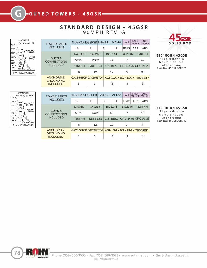
S O L I D R O D4545GSRGSR
Phone (309) 566-3000 • Fax (309) 566-3079 • www.rohnnet.com • The Industry Standard
G G U Y E D T O W E R S - 4 5 G S R
S T A N D A R D D E S I G N - 4 5 G S R
9 0 M P H R E V . G
78© 2011 ROHN PRODUCTS LLC
P/N: 45GSR90R320
320’ TOWER
308’47.7 39.5OR
400’
256’
5/16” EHS(1,120#)376’
275’
75’
195’
155’
1/4” EHS(665#)
348’
322’
235’
128’
35’133’
TOWER PARTS
INCLUDED
GUYS &
CONNECTIONS
INCLUDED
ANCHORS &
GROUNDING
INCLUDED
45GSR20 45GSRSB
1/4EHS BG2144 3/8THH
5/8TBE&J
TBSAFETYGAC3455TOP AGK1GGX BGK3GGX
16 1
5450’ 42 42
12
63 2 3
BASE
FB1G
GA45GD
8
142265
1275’
BG2146
6
7/16THH
6
1/2TBE&J
12
APL4A
1
CPC.5/.75
3
CPC1/1.25
3
GAC5655TOP
3
320’ ROHN 45GSR
Al l par ts shown intable are inc luded
when order ingPar t No: 45GSR90R320
TOWER PARTS
INCLUDED
GUYS &
CONNECTIONS
INCLUDED
ANCHORS &
GROUNDING
INCLUDED
45GSR20 45GSRSB
1/4EHS BG2144 3/8THH
5/8TBE&J
TBSAFETYGAC3455TOP AGK1GGX BGK3GGX
17 1
5975’ 42 42
12
63 2 3
BASE
FB1G
GA45GD
8
142265
1375’
BG2146
6
7/16THH
6
1/2TBE&J
12
APL4A
1
CPC.5/.75
3
CPC1/1.25
3
GAC5655TOP
3
340’ ROHN 45GSR
Al l par ts shown intable are inc luded
when order ingPar t No: 45GSR90R340
115’
148’
201’172’
P/N: 45GSR90R340
340’ TOWER
328’46.8 38.9OR
426’
272’
5/16” EHS(1,120#)401’
295’
95’
215’
175’
1/4” EHS(665#)
373’
347’
255’
144’
55’154’
135’
173’
227’197’
INNERANCHOR
AB2
OUTERANCHOR
AB3
INNERANCHOR
AB2
OUTERANCHOR
AB3

S O L I D R O D4545GSRGSR
S T A N D A R D D E S I G N - 4 5 G S R
1 1 0 M P H R E V . G
40’ ROHN 45GSR
Al l par ts shown in table
are included when order ing
Par t No: 45GSR110R040
P/N: 45GSR110R040
40’ TOWER
35’
66.9 48.2OR
47’
32’
1/4” EHS(665#)
Phone (309) 566-3000 • Fax (309) 566-3079 • www.rohnnet.com • The Industry Standard
GG U Y E D T O W E R S - 4 5 G S R
79© 2011 ROHN PRODUCTS LLC
60’ ROHN 45GSR
Al l par ts shown in table
are included when order ing
Par t No: 45GSR110R060
P/N: 45GSR110R060
60’ TOWER
55’
57.5 38.3OR
73’
48’
1/4” EHS(665#)
P/N: 45GSR110R080
80’ ROHN 45GSR
Al l par ts shown in table
are included when order ing
Par t No: 45GSR110R080
80’ TOWER
75’
52.7 35.5OR
99’
64’
1/4” EHS(665#)
73’35’
50’ ROHN 45GSR
Al l par ts shown in table
are included when order ing
Par t No: 45GSR110R050
P/N: 45GSR110R050
50’ TOWER
45’
63.1 46.0OR
60’
40’
1/4” EHS(665#)
P/N: 45GSR110R070
70’ ROHN 45GSR
Al l par ts shown in table
are included when order ing
Par t No: 45GSR110R070
70’ TOWER
65’
57.2 42.4OR
86’
56’
1/4” EHS(665#)
66’35’
TOWER PARTS
INCLUDED
GUYS &
CONNECTIONS
INCLUDED
ANCHORS &
GROUNDING
INCLUDED
45GSR20 45GSRSB GA45GD
1/4EHS BG2144 3/8THH 1/2TBE&J TBSAFETY
GAC3455TOP AGK1GGX BGK3GGX CPC.5/.75
2 1 1
150’ 6 6 3 3
3 31 3
FDNS
BASE ANCHOR
AB2FB2G
TOWER PARTS
INCLUDED
GUYS &
CONNECTIONS
INCLUDED
ANCHORS &
GROUNDING
INCLUDED
45GSR20 45GSRSB
1/4EHS BG2144 3/8THH 1/2TBE&J TBSAFETY
GAC3455TOP AGK1GGX BGK3GGX CPC.5/.75
2 1
200’ 6 6 3 3
3 31 3
FDNS
BASE ANCHOR
AB2FB2G
GA45GD
1
45GSR10
1
TOWER PARTS
INCLUDED
GUYS &
CONNECTIONS
INCLUDED
ANCHORS &
GROUNDING
INCLUDED
45GSR20 45GSRSB GA45GD
1/4EHS BG2144 3/8THH 1/2TBE&J TBSAFETY
GAC3455TOP AGK1GGX BGK3GGX CPC.5/.75
3 1 1
250’ 6 6 3 3
3 31 3
FDNS
BASE ANCHOR
AB2FB2G
TOWER PARTS
INCLUDED
GUYS &
CONNECTIONS
INCLUDED
ANCHORS &
GROUNDING
INCLUDED
45GSR20 45GSRSB
1/4EHS BG2144 3/8THH 1/2TBE&J TBSAFETY
GAC3455TOP AGK1GGX BGK3GGX CPC.5/.75
3 1
500’ 12 12 6 3
3 31 3
FDNS
BASE ANCHOR
AB2FB2G
GA45GD
2
45GSR10
1
TOWER PARTS
INCLUDED
GUYS &
CONNECTIONS
INCLUDED
ANCHORS &
GROUNDING
INCLUDED
45GSR20 45GSRSB GA45GD
1/4EHS BG2144 3/8THH 1/2TBE&J TBSAFETY
GAC3455TOP AGK1GGX BGK3GGX CPC.5/.75
4 1 2
550’ 12 12 6 3
3 31 3
FDNS
BASE ANCHOR
AB2FB2G

S O L I D R O D4545GSRGSR
Phone (309) 566-3000 • Fax (309) 566-3079 • www.rohnnet.com • The Industry Standard
G G U Y E D T O W E R S - 4 5 G S R
S T A N D A R D D E S I G N - 4 5 G S R
1 1 0 M P H R E V . G
80© 2011 ROHN PRODUCTS LLC
100’ ROHN 45GSR
Al l par ts shown in table
are included when order ing
Par t No: 45GSR110R100
P/N: 45GSR110R100
100’ TOWER
88’
44.5 32.6OR
119’
80’
1/4” EHS(665#)
97’55’
P/N: 45GSR110R090
90’ ROHN 45GSR
Al l par ts shown in table
are included when order ing
Par t No: 45GSR110R090
90’ TOWER
85’
49.4 33.0OR
111’
72’
1/4” EHS(665#)
85’45’
TOWER PARTS
INCLUDED
GUYS &
CONNECTIONS
INCLUDED
ANCHORS &
GROUNDING
INCLUDED
45GSR20 45GSRSB
1/4EHS BG2144 3/8THH 1/2TBE&J TBSAFETY
GAC3455TOP AGK1GGX BGK3GGX CPC.5/.75
4 1
625’ 12 12 6 3
3 31 3
FDNS
BASE ANCHOR
AB2FB2G
GA45GD
2
45GSR10
1
5/16” EHS(1,120#)
P/N: 45GSR110R110
110’ TOWER
98’
43.0 31.7OR
132’
88’
1/4” EHS(665#)
109’
65’
35’ 95’
5/16” EHS(1,120#)
P/N: 45GSR110R120
120’ TOWER
108’
41.4 30.7OR
144’
96’
1/4” EHS(665#)
122’
75’
35’ 102’
5/16” EHS(1,120#)
TOWER PARTS
INCLUDED
GUYS &
CONNECTIONS
INCLUDED
ANCHORS &
GROUNDING
INCLUDED
45GSR20 45GSRSB GA45GD
1/4EHS 142265 3/8THH 1/2TBE&J 5/8TBE&J
GAC3455TOP AGK1GGX BGK3GGX CPC.5/.75
5 1 2
325’ 400’ 6 3 3
3 31 3
FDNS
BASE ANCHOR
AB2FB2G
7/16THH BG2144 BG2146 TBSAFETY
6 6 6 3
TOWER PARTS
INCLUDED
GUY WIRE &
CONNECTION
INCLUDED
ANCHORS &
GROUNDING
INCLUDED
45GSR20 45GSRSB GA45GD
1/4EHS 142265 3/8THH 1/2TBE&J 5/8TBE&J
GAC3455TOP AGK1GGX BGK3GGX CPC.5/.75
5 1 3
650’ 425’ 12 6 3
3 31 3
FDNS
BASE ANCHOR
AB2FB2G
7/16THH BG2144 BG2146 TBSAFETY
6 12 6 3
45GSR10
1
120’ ROHN 45GSR
Al l par ts shown in table
are included when order ing
Par t No: 45GSR110R120
TOWER PARTS
INCLUDED
GUYS &
CONNECTIONS
INCLUDED
ANCHORS &
GROUNDING
INCLUDED
45GSR20 45GSRSB GA45GD
1/4EHS 142265 3/8THH 1/2TBE&J 5/8TBE&J
GAC3455TOP AGK1GGX BGK3GGX CPC.5/.75
6 1 3
725’ 475’ 12 6 3
3 31 3
FDNS
BASE ANCHOR
AB2FB2G
7/16THH BG2144 BG2146 TBSAFETY
6 12 6 3
110’ ROHN 45GSR
Al l par ts shown in table
are included when order ing
Par t No: 45GSR110R110

S O L I D R O D4545GSRGSR
Phone (309) 566-3000 • Fax (309) 566-3079 • www.rohnnet.com • The Industry Standard
GG U Y E D T O W E R S - 4 5 G S R
S T A N D A R D D E S I G N - 4 5 G S R
1 1 0 M P H R E V . G
81© 2011 ROHN PRODUCTS LLC
P/N: 45GSR110R140
140’ TOWER
128’
39.4 29.3OR
170’
112’
5/16” EHS(1,120#)
147’
95’
55’ 125’
1/4” EHS(665#)
P/N: 45GSR110R160
160’ TOWER
148’
37.5 28.2OR
196’
128’
5/16” EHS(1,120#)172’
115’
35’ 133’
75’148’ 1/4” EHS
(665#)
P/N: 45GSR110R150
150’ TOWER
138’
38.3 28.7OR
183’
120’
159’
105’
35’ 125’
65’136’
5/16” EHS(1,120#)
1/4” EHS(665#)
P/N: 45GSR110R130
130’ TOWER
118’
40.5 29.9OR
157’
104’
5/16” EHS(1,120#)
134’
85’
45’ 113’
1/4” EHS(665#)
TOWER PARTS
INCLUDED
GUYS &
CONNECTIONS
INCLUDED
ANCHORS &
GROUNDING
INCLUDED
45GSR20 45GSRSB GA45GD
1/4EHS 142265 3/8THH 1/2TBE&J 5/8TBE&J
GAC3455TOP AGK1GGX BGK3GGX CPC.5/.75
6 1 3
800’ 500’ 12 6 3
3 31 3
FDNS
BASE ANCHOR
AB2FB2G
7/16THH BG2144 BG2146 TBSAFETY
6 12 6 3
45GSR10
1
130’ ROHN 45GSR
Al l par ts shown in table
are included when order ing
Par t No: 45GSR110R130
140’ ROHN 45GSR
Al l par ts shown in table
are included when order ing
Par t No: 45GSR110R140
TOWER PARTS
INCLUDED
GUYS &
CONNECTIONS
INCLUDED
ANCHORS &
GROUNDING
INCLUDED
45GSR20 45GSRSB GA45GD
1/4EHS 142265 3/8THH 1/2TBE&J 5/8TBE&J
GAC3455TOP AGK1GGX BGK3GGX CPC.5/.75
7 1 3
875’ 550’ 12 6 3
3 31 3
FDNS
BASE ANCHOR
AB2FB2G
7/16THH BG2144 BG2146 TBSAFETY
6 12 6 3
TOWER PARTS
INCLUDED
GUYS &
CONNECTIONS
INCLUDED
ANCHORS &
GROUNDING
INCLUDED
45GSR20 45GSRSB GA45GD
1/4EHS 142265 3/8THH 5/8TBE&J
GAC5655TOP AGK1GGX BGK3GGX CPC1/1.25
7 1 4
1350’ 600’ 18 12
3 31 3
FDNS
BASE ANCHOR
AB3FB2G
7/16THH BG2144 BG2146 TBSAFETY
6 18 6 3
45GSR10
1
150’ ROHN 45GSR
Al l par ts shown in table
are included when order ing
Par t No: 45GSR110R150
160’ ROHN 45GSR
Al l par ts shown in table
are included when order ing
Par t No: 45GSR110R160
TOWER PARTS
INCLUDED
GUYS &
CONNECTIONS
INCLUDED
ANCHORS &
GROUNDING
INCLUDED
45GSR20 45GSRSB GA45GD
1/4EHS 142265 3/8THH 5/8TBE&J
GAC5655TOP AGK1GGX BGK3GGX CPC1/1.25
8 1 4
1450’ 625’ 18 12
3 31 3
FDNS
BASE ANCHOR
AB3FB2G
7/16THH BG2144 BG2146 TBSAFETY
6 18 6 3

S O L I D R O D4545GSRGSR
Phone (309) 566-3000 • Fax (309) 566-3079 • www.rohnnet.com • The Industry Standard
G G U Y E D T O W E R S - 4 5 G S R
S T A N D A R D D E S I G N - 4 5 G S R
1 1 0 M P H R E V . G
82© 2011 ROHN PRODUCTS LLC
P/N: 45GSR110R200
200’ TOWER
188’34.6 26.6OR
247’
160’
5/16” EHS(1,120#)223’
155’
35’
115’
197’ 1/4” EHS(665#)
177’
164’
75’
P/N: 45GSR110R190
190’ TOWER
178’35.1 26.9OR
234’
152’
210’
145’
35’
105’
185’
5/16” EHS(1,120#)
165’
156’
65’1/4” EHS
(665#)
P/N: 45GSR110R180
180’ TOWER
168’
35.7 27.3OR
221’
144’
5/16” EHS(1,120#)197’
135’
55’ 154’
95’173’ 1/4” EHS
(665#)
P/N: 45GSR110R170
170’ TOWER
158’
36.8 27.8OR
208’
136’
185’
125’
45’ 143’
85’160’ 1/4” EHS
(665#)
5/16” EHS(1,120#)
TOWER PARTS
INCLUDED
GUYS &
CONNECTIONS
INCLUDED
ANCHORS &
GROUNDING
INCLUDED
45GSR20 45GSRSB GA45GD
1/4EHS 142265 3/8THH 5/8TBE&J
GAC5655TOP AGK1GGX BGK3GGX CPC1/1.25
8 1 4
1575’ 675’ 18 12
3 31 3
FDNS
BASE ANCHOR
AB3FB2G
7/16THH BG2144 BG2146 TBSAFETY
6 18 6 3
45GSR10
1
170’ ROHN 45GSR
Al l par ts shown in table
are included when order ing
Par t No: 45GSR110R170
180’ ROHN 45GSR
Al l par ts shown in table
are included when order ing
Par t No: 45GSR110R180
TOWER PARTS
INCLUDED
GUYS &
CONNECTIONS
INCLUDED
ANCHORS &
GROUNDING
INCLUDED
45GSR20 45GSRSB GA45GD
1/4EHS 142265 3/8THH 5/8TBE&J
GAC5655TOP AGK1GGX BGK3GGX CPC1/1.25
9 1 4
1675’ 725’ 18 12
3 31 3
FDNS
BASE ANCHOR
AB3FB2G
7/16THH BG2144 BG2146 TBSAFETY
6 18 6 3
TOWER PARTS
INCLUDED
GUYS &
CONNECTIONS
INCLUDED
ANCHORS &
GROUNDING
INCLUDED
45GSR20 45GSRSB GA45GD
1/4EHS 142265 3/8THH 5/8TBE&J
GAC5655TOP AGK1GGX BGK3GGX CPC1/1.25
9 1 5
2300’ 750’ 24 15
3 31 3
FDNS
BASE ANCHOR
AB3FB2G
7/16THH BG2144 BG2146 TBSAFETY
6 24 6 3
45GSR10
1
190’ ROHN 45GSR
Al l par ts shown in table
are included when order ing
Par t No: 45GSR110R190
200’ ROHN 45GSR
Al l par ts shown in table
are included when order ing
Par t No: 45GSR110R200
TOWER PARTS
INCLUDED
GUYS &
CONNECTIONS
INCLUDED
ANCHORS &
GROUNDING
INCLUDED
45GSR20 45GSRSB GA45GD
1/4EHS 142265 3/8THH 5/8TBE&J
GAC5655TOP AGK1GGX BGK3GGX CPC1/1.25
10 1 5
2425’ 800’ 24 15
3 31 3
FDNS
BASE ANCHOR
AB4FB2G
7/16THH BG2144 BG2146 TBSAFETY
6 24 6 3
APL4A
1

S O L I D R O D4545GSRGSR
Phone (309) 566-3000 • Fax (309) 566-3079 • www.rohnnet.com • The Industry Standard
GG U Y E D T O W E R S - 4 5 G S R
S T A N D A R D D E S I G N - 4 5 G S R
1 1 0 M P H R E V . G
83© 2011 ROHN PRODUCTS LLC
P/N: 45GSR110R240
240’ TOWER
228’32.2 25.1OR
298’
192’
1/4” EHS(665#)
274’
195’
35’
115’
75’
102’
122’
5/16” EHS(1,120#)
247’
150’
155’
96’
P/N: 45GSR110R260
260’ TOWER
248’31.0 24.5OR
324’
208’
5/16” EHS(1,120#)299’
215’
55’
135’
95’
125’
147’
1/4” EHS(665#)
272’
175’
175’
112’
P/N: 45GSR110R280
280’ TOWER
268’30.4 24.0OR
349’
224’
5/16” EHS(1,120#)325’
235’
75’
155’
115’
122’
150’
1/4” EHS(665#)
297’
272’
195’
96’
35’102’
P/N: 45GSR110R220
220’ TOWER
208’33.3 25.8OR
273’
176’
1/4” EHS(665#)
248’
175’
55’
135’
222’95’
184’
200’
5/16” EHS(1,120#)
220’ ROHN 45GSR
Al l par ts shown in tableare included when order ing
Par t No: 45GSR110R220
TOWER PARTS
INCLUDED
GUYS &
CONNECTIONS
INCLUDED
ANCHORS &
GROUNDING
INCLUDED
45GSR20 45GSRSB GA45GD
1/4EHS 142265 3/8THH 5/8TBE&J
GAC5655TOP AGK1GGX BGK3GGX CPC1/1.25
11 1 5
2725’ 875’ 24 15
3 31 3
FDNS
BASE ANCHOR
AB4FB2G
7/16THH BG2144 BG2146 TBSAFETY
6 24 6 3
APL4A
1
260’ ROHN 45GSR
Al l par ts shown in tableare included when order ing
Par t No: 45GSR110R260
TOWER PARTS
INCLUDED
GUYS &
CONNECTIONS
INCLUDED
ANCHORS &
GROUNDING
INCLUDED
45GSR20 45GSRSB
1/4EHS BG2144 3/8THH
5/8TBE&J
TBSAFETYGAC3455TOP AGK1GGX BGK3GGX
CPC.5/.75
12 1
2850’ 30 30
9
63
3
2 3
BASE INNERANCHOR
AB2FB2G
GA45GD
6
142265
950’
BG2146
6
7/16THH
6
240’ ROHN 45GSR
Al l par ts shown intable are inc luded
when order ingPar t No: 45GSR110R240
1/2TBE&J
9
APL4A
1
CPC1/1.25
3
GAC5655TOP
3
TOWER PARTS
INCLUDED
GUYS &
CONNECTIONS
INCLUDED
ANCHORS &
GROUNDING
INCLUDED
45GSR20 45GSRSB
1/4EHS BG2144 3/8THH
5/8TBE&J
TBSAFETYGAC3455TOP AGK1GGX BGK3GGX
CPC.5/.75
13 1
3250’ 30 30
9
63
3
2 3
BASE
FB2G
GA45GD
6
142265
1050’
BG2146
6
7/16THH
6
1/2TBE&J
9
APL4A
1
CPC1/1.25
3
GAC5655TOP
3
OUTERANCHOR
AB3
INNERANCHOR
AB2
OUTERANCHOR
AB3
280’ ROHN 45GSR
Al l par ts shown in tableare included when order ing
Par t No: 45GSR110R280
TOWER PARTS
INCLUDED
GUYS &
CONNECTIONS
INCLUDED
ANCHORS &
GROUNDING
INCLUDED
45GSR20 45GSRSB
1/4EHS BG2144 3/8THH
5/8TBE&J
TBSAFETYGAC3455TOP AGK1GGX BGK3GGX
CPC.5/.75
14 1
4050’ 36 36
12
63
3
2 3
BASE
FB2G
GA45GD
7
142265
1125’
BG2146
6
7/16THH
6
1/2TBE&J
9
APL4A
1
CPC1/1.25
3
GAC5655TOP
3
INNERANCHOR
AB2
OUTERANCHOR
AB4

S O L I D R O D4545GSRGSR
Phone (309) 566-3000 • Fax (309) 566-3079 • www.rohnnet.com • The Industry Standard
G G U Y E D T O W E R S - 4 5 G S R
S T A N D A R D D E S I G N - 4 5 G S R
1 1 0 M P H R E V . G
84© 2011 ROHN PRODUCTS LLC
P/N: 45GSR110R300
300’ TOWER
288’29.7 23.5OR
375’
240’
1/4” EHS(665#)
345’
248’
95’
175’
135’
147’
175’
5/16” EHS(1,120#)
322’
297’
215’
112’
55’
125’
300’ ROHN 45GSR
Al l par ts shown in tableare included when order ing
Par t No: 45GSR110R300
TOWER PARTS
INCLUDED
GUYS &
CONNECTIONS
INCLUDED
ANCHORS &
GROUNDING
INCLUDED
45GSR20 45GSRSB
1/4EHS BG2144 3/8THH
5/8TBE&J
TBSAFETYGAC3455TOP AGK1GGX BGK3GGX
CPC.5/.75
15 1
3400’ 30 30
12
63
3
2 3
BASE
FB2G
GA45GD
7
142265
2300’
BG2146
12
7/16THH
12
1/2TBE&J
9
APL4A
1
CPC1/1.25
3
GAC5655TOP
3
INNERANCHOR
AB2
OUTERANCHOR
AB4
320’ ROHN 45GSR
Al l par ts shown in tableare included when order ing
Par t No: 45GSR110R320
TOWER PARTS
INCLUDED
GUYS &
CONNECTIONS
INCLUDED
ANCHORS &
GROUNDING
INCLUDED
45GSR20 45GSRSB
1/4EHS BG2146
1/2THH 5/8TBE&J
TBSAFETYAGK1GGX BGK3GGX
15 1
4225’ 6
6 24
62 3
BASE
FB2G
GA45GD
7
142265
1200’
BG2147
6
7/16THH
6
5/8S
3
APL4A
1
CPC1/1.25
6
GAC5655TOP
6
INNERANCHOR
AB3
OUTERANCHOR
AB4
P/N: 45GSR110R320
320’ TOWER
308’28.9 23.0OR
401’
256’
5/16” EHS(1,120#)
371’
268’
75’
195’
155’
1/4” EHS(665#)
348’
322’
235’
128’
35’133’
115’
148’
201’172’
P/N: 45GSR110R340
340’ TOWER
328’28.1 22.6OR
426’
272’
5/16” EHS(1,120#)
396’
288’
95’
215’
175’
1/4” EHS(665#)
373’
347’
255’
144’
55’154’
135’
173’
227’197’
3/8” EHS(1,540#)
142261
1300’
3/8THH
36
BG2144
36
5/8S
3
45GSR20L82*
1
340’ ROHN 45GSR
Al l par ts shown in tableare included when order ing
Par t No: 45GSR110R340
TOWER PARTS
INCLUDED
GUYS &
CONNECTIONS
INCLUDED
ANCHORS &
GROUNDING
INCLUDED
45GSR20 45GSRSB
1/4EHS BG2146
1/2THH 5/8TBE&J
TBSAFETYAGK1GGX BGK3GGX
16 1
4700’ 6
6 24
62 3
BASE
FB2G
GA45GD
7
142265
1275’
BG2147
6
7/16THH
6
5/8S
3
APL4A
1
CPC1/1.25
6
GAC5655TOP
6
INNERANCHOR
AB3
OUTERANCHOR
AB4
142261
1375’
3/8THH
36
BG2144
36
5/8S
3
45GSR20L82*
1
3/8” EHS(1,540#)
* Guy lug sections required for 3/8” guys.

S O L I D R O D4545GSRGSR
S T A N D A R D D E S I G N - 4 5 G S R
1 3 0 M P H R E V . G
40’ ROHN 45GSR
Al l par ts shown in table
are included when order ing
Par t No: 45GSR130R040
P/N: 45GSR130R040
40’ TOWER
35’
47.3 33.5OR
47’
32’
1/4” EHS(665#)
Phone (309) 566-3000 • Fax (309) 566-3079 • www.rohnnet.com • The Industry Standard
GG U Y E D T O W E R S - 4 5 G S R
85© 2011 ROHN PRODUCTS LLC
60’ ROHN 45GSR
Al l par ts shown in table
are included when order ing
Par t No: 45GSR90R060
P/N: 45GSR130R060
60’ TOWER
48’
35.0 24.0OR
68’
48’
5/16” EHS(1,120#)
50’ ROHN 45GSR
Al l par ts shown in table
are included when order ing
Par t No: 45GSR90R050
P/N: 45GSR130R050
50’ TOWER
45’
44.1 28.6OR
60’
40’
1/4” EHS(665#)
P/N: 45GSR130R070
70’ ROHN 45GSR
Al l par ts shown in table
are included when order ing
Par t No: 45GSR130R070
70’ TOWER
58’
33.2 22.8OR
81’
56’
1/4” EHS(665#)66’
35’
TOWER PARTS
INCLUDED
GUYS &
CONNECTIONS
INCLUDED
ANCHORS &
GROUNDING
INCLUDED
45GSR20 45GSRSB GA45GD
1/4EHS BG2144 3/8THH 1/2TBE&J TBSAFETY
GAC3455TOP AGK1GGX BGK3GGX CPC.5/.75
2 1 1
150’ 6 6 3 3
3 31 3
FDNS
BASE ANCHOR
AB2FB2G
TOWER PARTS
INCLUDED
GUYS &
CONNECTIONS
INCLUDED
ANCHORS &
GROUNDING
INCLUDED
45GSR20 45GSRSB
1/4EHS BG2144 3/8THH 1/2TBE&J TBSAFETY
GAC3455TOP AGK1GGX BGK3GGX CPC.5/.75
2 1
200’ 6 6 3 3
3 31 3
FDNS
BASE ANCHOR
AB2FB2G
GA45GD
1
45GSR10
1
TOWER PARTS
INCLUDED
GUYS &
CONNECTIONS
INCLUDED
ANCHORS &
GROUNDING
INCLUDED
45GSR20 45GSRSB GA45GD
142265 BG2146 7/16THH 5/8TBE&J TBSAFETY
GAC3455TOP AGK1GGX BGK3GGX CPC.5/.75
3 1 1
225’ 6 6 3 3
3 31 3
FDNS
BASE ANCHOR
AB2FB2G
TOWER PARTS
INCLUDED
GUYS &
CONNECTIONS
INCLUDED
ANCHORS &
GROUNDING
INCLUDED
45GSR20 45GSRSB
1/4EHS BG2144 3/8THH
1/2TBE&J TBSAFETY
3 1
225’ 6 6
3 3
FDNS
BASE ANCHOR
AB2FB2G
GA45GD
2
45GSR10
15/16” EHS(1,120#)
142265
275’
5/8TBE&J
3
7/16THH
6
BG2146
6
GAC3455TOP AGK1GGX BGK3GGX CPC.5/.75
3 31 3

S O L I D R O D4545GSRGSR
Phone (309) 566-3000 • Fax (309) 566-3079 • www.rohnnet.com • The Industry Standard
G G U Y E D T O W E R S - 4 5 G S R
S T A N D A R D D E S I G N - 4 5 G S R
1 3 0 M P H R E V . G
86© 2011 ROHN PRODUCTS LLC
P/N: 45GSR130R100
100’ TOWER
88’
29.1 20.5OR
119’
80’
1/4” EHS(665#)
97’55’
P/N: 45GSR130R090
90’ TOWER
78’
30.2 21.1OR
106’
72’
1/4” EHS(665#)
85’45’
P/N: 45GSR130R110
110’ TOWER
98’
28.0 19.9OR
132’
88’
1/4” EHS(665#)
109’
65’
35’ 95’
P/N: 45GSR130R080
80’ ROHN 45GSR
Al l par ts shown in table
are included when order ing
Par t No: 45GSR130R080
80’ TOWER
68’
31.5 21.9OR
93’
64’
1/4” EHS(665#)
73’35’
5/16” EHS(1,120#)
TOWER PARTS
INCLUDED
GUYS &
CONNECTIONS
INCLUDED
ANCHORS &
GROUNDING
INCLUDED
45GSR20 45GSRSB
1/4EHS BG2144 3/8THH
1/2TBE&J TBSAFETY
4 1
250’ 6 6
3 3
FDNS
BASE ANCHOR
AB2FB2G
GA45GD
2
142265
300’
5/8TBE&J
3
7/16THH
6
BG2146
6
GAC3455TOP AGK1GGX BGK3GGX CPC.5/.75
3 31 3
TOWER PARTS
INCLUDED
GUYS &
CONNECTIONS
INCLUDED
ANCHORS &
GROUNDING
INCLUDED
45GSR20 45GSRSB
1/4EHS BG2144 3/8THH
1/2TBE&J TBSAFETY
4 1
275’ 6 6
3 3
FDNS
BASE ANCHOR
AB2FB2G
GA45GD
2
45GSR10
1
142265
350’
5/8TBE&J
3
7/16THH
6
BG2146
6
GAC3455TOP AGK1GGX BGK3GGX CPC.5/.75
3 31 3
90’ ROHN 45GSR
Al l par ts shown in table
are included when order ing
Par t No: 45GSR130R090
5/16” EHS(1,120#)
100’ ROHN 45GSR
Al l par ts shown in table
are included when order ing
Par t No: 45GSR130R100
TOWER PARTS
INCLUDED
GUYS &
CONNECTIONS
INCLUDED
ANCHORS &
GROUNDING
INCLUDED
45GSR20 45GSRSB
1/4EHS BG2144 3/8THH
1/2TBE&J TBSAFETY
5 1
325’ 6 6
3 3
FDNS
BASE ANCHOR
AB2FB2G
GA45GD
2
142265
400’
5/8TBE&J
3
7/16THH
6
BG2146
6
GAC3455TOP AGK1GGX BGK3GGX CPC.5/.75
3 31 3
5/16” EHS(1,120#)
TOWER PARTS
INCLUDED
GUYS &
CONNECTIONS
INCLUDED
ANCHORS &
GROUNDING
INCLUDED
45GSR20 45GSRSB
1/4EHS BG2144
3/8THH TBSAFETY
5 1
650’ 12
12 3
FDNS
BASE ANCHOR
AB3FB2G
GA45GD
3
45GSR10
1
142265
425’
5/8TBE&J
9
7/16THH
6
BG2146
6
GAC5655TOP AGK1GGX BGK3GGX CPC1/1.25
3 31 3
110’ ROHN 45GSR
Al l par ts shown in table
are included when order ing
Par t No: 45GSR130R110
5/16” EHS(1,120#)

S O L I D R O D4545GSRGSR
Phone (309) 566-3000 • Fax (309) 566-3079 • www.rohnnet.com • The Industry Standard
GG U Y E D T O W E R S - 4 5 G S R
S T A N D A R D D E S I G N - 4 5 G S R
1 3 0 M P H R E V . G
87© 2011 ROHN PRODUCTS LLC
120’ ROHN 45GSR
Al l par ts shown in table
are included when order ing
Par t No: 45GSR130R120
TOWER PARTS
INCLUDED
GUYS &
CONNECTIONS
INCLUDED
ANCHORS &
GROUNDING
INCLUDED
45GSR20 45GSRSB
1/4EHS BG2144
3/8THH TBSAFETY
6 1
725’ 12
12 3
FDNS
BASE ANCHOR
AB3FB2G
GA45GD
3
142265
475’
5/8TBE&J
9
7/16THH
6
BG2146
6
GAC5655TOP AGK1GGX BGK3GGX CPC1/1.25
3 31 3
TOWER PARTS
INCLUDED
GUYS &
CONNECTIONS
INCLUDED
ANCHORS &
GROUNDING
INCLUDED
45GSR20 45GSRSB
1/4EHS BG2144
3/8THH TBSAFETY
6 1
800’ 12
12 3
FDNS
BASE ANCHOR
AB3FB2G
GA45GD
3
45GSR10
1
142265
500’
5/8TBE&J
9
7/16THH
6
BG2146
6
GAC5655TOP AGK1GGX BGK3GGX CPC1/1.25
3 31 3
130’ ROHN 45GSR
Al l par ts shown in table
are included when order ing
Par t No: 45GSR130R130
P/N: 45GSR130R120
120’ TOWER
108’
27.0 19.3OR
144’
96’
1/4” EHS(665#)
122’
75’
35’ 102’
P/N: 45GSR130R130
130’ TOWER
118’
26.3 18.7OR
157’
104’
5/16” EHS(1,120#)
134’
85’
45’ 113’
1/4” EHS(665#)
5/16” EHS(1,120#)
140’ ROHN 45GSR
Al l par ts shown in table
are included when order ing
Par t No: 45GSR130R140
TOWER PARTS
INCLUDED
GUYS &
CONNECTIONS
INCLUDED
ANCHORS &
GROUNDING
INCLUDED
45GSR20 45GSRSB
1/4EHS BG2144
3/8THH TBSAFETY
7 1
875’ 12
12 3
FDNS
BASE ANCHOR
AB3FB2G
GA45GD
3
142265
550’
5/8TBE&J
9
7/16THH
6
BG2146
6
GAC5655TOP AGK1GGX BGK3GGX CPC1/1.25
3 31 3
P/N: 45GSR130R140
140’ TOWER
128’
25.6 18.4OR
170’
112’
5/16” EHS(1,120#)
147’
95’
55’ 125’
1/4” EHS(665#)
P/N: 45GSR130R150
150’ TOWER
138’
24.7 18.0OR
183’
120’
159’
105’
35’ 125’
65’136’
5/16” EHS(1,120#)
1/4” EHS(665#)
TOWER PARTS
INCLUDED
GUYS &
CONNECTIONS
INCLUDED
ANCHORS &
GROUNDING
INCLUDED
45GSR20 45GSRSB
1/4EHS BG2144
3/8THH TBSAFETY
7 1
1350’ 18
18 3
FDNS
BASE ANCHOR
AB4FB2G
GA45GD
4
45GSR10
1
142265
600’
3/4TBE&J
12
7/16THH
6
BG2146
6
GAC5755TOP AGK1GGX BGK3GGX CPC1.5/2
3 31 3
150’ ROHN 45GSR
Al l par ts shown in table
are included when order ing
Par t No: 45GSR130R150
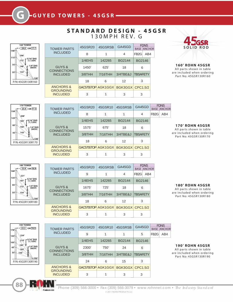
S O L I D R O D4545GSRGSR
Phone (309) 566-3000 • Fax (309) 566-3079 • www.rohnnet.com • The Industry Standard
G G U Y E D T O W E R S - 4 5 G S R
S T A N D A R D D E S I G N - 4 5 G S R
1 3 0 M P H R E V . G
88© 2011 ROHN PRODUCTS LLC
160’ ROHN 45GSR
Al l par ts shown in table
are included when order ing
Par t No: 45GSR130R160
TOWER PARTS
INCLUDED
GUYS &
CONNECTIONS
INCLUDED
ANCHORS &
GROUNDING
INCLUDED
45GSR20 45GSRSB
1/4EHS BG2144
3/8THH TBSAFETY
8 1
1450’ 18
18 3
FDNS
BASE ANCHOR
AB4FB2G
GA45GD
4
142265
625’
3/4TBE&J
12
7/16THH
6
BG2146
6
GAC5755TOP AGK1GGX BGK3GGX CPC1.5/2
3 31 3
TOWER PARTS
INCLUDED
GUYS &
CONNECTIONS
INCLUDED
ANCHORS &
GROUNDING
INCLUDED
45GSR20 45GSRSB
1/4EHS BG2144
3/8THH TBSAFETY
8 1
1575’ 18
18 3
FDNS
BASE ANCHOR
AB4FB2G
GA45GD
4
45GSR10
1
142265
675’
3/4TBE&J
12
7/16THH
6
BG2146
6
GAC5755TOP AGK1GGX BGK3GGX CPC1.5/2
3 31 3
170’ ROHN 45GSR
Al l par ts shown in table
are included when order ing
Par t No: 45GSR130R170
P/N: 45GSR130R160
160’ TOWER
148’
24.0 17.7OR
196’
128’
5/16” EHS(1,120#)172’
115’
35’ 133’
75’148’ 1/4” EHS
(665#)
P/N: 45GSR130R170
170’ TOWER
158’
23.4 17.3OR
208’
136’
185’
125’
45’ 143’
85’160’ 1/4” EHS
(665#)
5/16” EHS(1,120#)
P/N: 45GSR130R190
190’ TOWER
178’22.3 16.5OR
234’
152’
210’
145’
35’
105’
185’
5/16” EHS(1,120#)
165’
156’
65’1/4” EHS
(665#)
P/N: 45GSR130R180
180’ TOWER
168’
22.8 16.9OR
221’
144’
5/16” EHS(1,120#)197’
135’
55’ 154’
95’173’ 1/4” EHS
(665#)
180’ ROHN 45GSR
Al l par ts shown in table
are included when order ing
Par t No: 45GSR130R180
TOWER PARTS
INCLUDED
GUYS &
CONNECTIONS
INCLUDED
ANCHORS &
GROUNDING
INCLUDED
45GSR20 45GSRSB
1/4EHS BG2144
3/8THH TBSAFETY
9 1
1675’ 18
18 3
FDNS
BASE ANCHOR
AB4FB2G
GA45GD
4
142265
725’
3/4TBE&J
12
7/16THH
6
BG2146
6
GAC5755TOP AGK1GGX BGK3GGX CPC1.5/2
3 31 3
TOWER PARTS
INCLUDED
GUYS &
CONNECTIONS
INCLUDED
ANCHORS &
GROUNDING
INCLUDED
45GSR20 45GSRSB
1/4EHS BG2144
3/8THH TBSAFETY
9 1
2300’ 24
24 3
FDNS
BASE ANCHOR
AB4FB2G
GA45GD
5
45GSR10
1
142265
750’
3/4TBE&J
15
7/16THH
6
BG2146
6
GAC5755TOP AGK1GGX BGK3GGX CPC1.5/2
3 31 3
190’ ROHN 45GSR
Al l par ts shown in table
are included when order ing
Par t No: 45GSR130R190

S O L I D R O D4545GSRGSR
Phone (309) 566-3000 • Fax (309) 566-3079 • www.rohnnet.com • The Industry Standard
GG U Y E D T O W E R S - 4 5 G S R
S T A N D A R D D E S I G N - 4 5 G S R
1 3 0 M P H R E V . G
89© 2011 ROHN PRODUCTS LLC
P/N: 45GSR130R240
240’ TOWER
228’20.2 15.0OR
298’
192’
1/4” EHS(665#)
269’
188’
35’
108’
75’
102’
122’
5/16” EHS(1,120#)
247’
144’
155’
96’
P/N: 45GSR130R200
200’ TOWER
188’21.9 16.2OR
247’
160’
5/16” EHS(1,120#)218’
148’
35’
115’
197’ 1/4” EHS(665#)
177’
164’
75’
P/N: 45GSR130R220
220’ TOWER
208’21.0 15.5OR
272’
176’
1/4” EHS(665#)
243’
168’
55’
135’
222’95’
184’
200’
5/16” EHS(1,120#)
200’ ROHN 45GSR
Al l par ts shown in tableare included when order ing
Par t No: 45GSR130R200
220’ ROHN 45GSR
Al l par ts shown in tableare included when order ing
Par t No: 45GSR130R220
3/8” EHS(1,540#)
TOWER PARTS
INCLUDED
GUYS &
CONNECTIONS
INCLUDED
ANCHORS &
GROUNDING
INCLUDED
45GSR20 45GSRSB
1/4EHS BG2144
3/8THH TBSAFETY
10 1
1725’ 18
18 3
FDNS
BASE ANCHOR
AB4FB2G
GA45GD
5
142265
1500’
3/4TBE&J
15
7/16THH
12
BG2146
12
GAC5755TOP AGK1GGX BGK3GGX CPC1.5/2
3 31 3
APL4A
1
TOWER PARTS
INCLUDED
GUYS &
CONNECTIONS
INCLUDED
ANCHORS &
GROUNDING
INCLUDED
45GSR20 45GSRSB
1/4EHS 142261
BG2146 1/2THH
10 1
1950’ 875’
6 6
FDNS
BASE ANCHOR
AB4FB2G
GA45GD
4
142265
775’
7/16THH
6
BG2147
6
BG2144
18
GAC5755TOP AGK1GGX BGK3GGX CPC1.5/2
3 31 3
APL4A
1
3/8THH TBSAFETY
18 3
3/4TBE&J
15
5/8S
3
240’ ROHN 45GSR
Al l par ts shown in tableare included when order ing
Par t No: 45GSR130R240
TOWER PARTS
INCLUDED
GUYS &
CONNECTIONS
INCLUDED
ANCHORS &
GROUNDING
INCLUDED
45GSR20 45GSRSB
1/4EHS 142261
BG2146 1/2THH
11 1
1500’ 950’
12 6
BASE INNERANCHOR
AB3FB2G
GA45GD
5
142265
1325’
7/16THH
12
BG2147
6
BG2144
18
GAC5655TOP AGK1GGX BGK3GGX CPC1/1.25
6 62 3
APL4A
1
3/8THH TBSAFETY
18 6
5/8TBE&J
18
5/8S
3
3/8” EHS(1,540#)
OUTERANCHOR
AB4
45GSR20L82*
1
45GSR20L82*
1
* Guy lug section required for 3/8” guys.

S O L I D R O D4545GSRGSR
Phone (309) 566-3000 • Fax (309) 566-3079 • www.rohnnet.com • The Industry Standard
G G U Y E D T O W E R S - 4 5 G S R
S T A N D A R D D E S I G N - 4 5 G S R
1 3 0 M P H R E V . G
90© 2011 ROHN PRODUCTS LLC
260’ ROHN 45GSR
Al l par ts shown in tableare included when order ing
Par t No: 45GSR130R260
TOWER PARTS
INCLUDED
GUYS &
CONNECTIONS
INCLUDED
ANCHORS &
GROUNDING
INCLUDED
45GSR20 45GSRSB
1/4EHS 142261
BG2146 1/2THH
12 1
1750’ 1050’
12 6
BASE INNERANCHOR
AB3FB2G
GA45GD
5
142265
1500’
7/16THH
12
BG2147
6
BG2144
18
GAC5655TOP AGK1GGX BGK3GGX CPC1/1.25
6 62 3
APL4A
1
3/8THH TBSAFETY
18 6
5/8TBE&J
18
5/8S
3
OUTERANCHOR
AB4
45GSR20L82*
1
P/N: 45GSR130R260
260’ TOWER
248’19.6 14.6OR
324’
208’
3/8” EHS(1,540#)294’
208’
55’
128’
95’
125’
147’
1/4” EHS(665#)
272’
170’
175’
112’
P/N: 45GSR130R280
280’ TOWER
268’19.0 14.3OR
349’
224’
3/8” EHS(1,540#)320’
228’
75’
148’
115’
122’
150’
1/4” EHS(665#)
292’
268’
188’
96’
35’102’
P/N: 45GSR130R300
300’ TOWER
288’18.4 14.0OR
375’
240’
1/4” EHS(665#)
345’
248’
95’
168’
135’
147’
175’
3/8” EHS(1,540#)
318’
293’
208’
112’
55’
125’
280’ ROHN 45GSR
Al l par ts shown in tableare included when order ing
Par t No: 45GSR130R280
TOWER PARTS
INCLUDED
GUYS &
CONNECTIONS
INCLUDED
ANCHORS &
GROUNDING
INCLUDED
45GSR20 45GSRSB
1/4EHS 142261
BG2146 1/2THH
13 1
1200’ 1125’
18 6
BASE INNERANCHOR
AB3FB2G
GA45GD
6
142265
2800’
7/16THH
18
BG2147
6
BG2144
18
GAC5755TOP AGK1GGX BGK3GGX CPC1.5/2
6 62 3
APL4A
1
3/8THH TBSAFETY
18 6
3/4TBE&J
21
5/8S
3
OUTERANCHOR
AB5
45GSR20L82*
15/16” EHS(1,120#)
300’ ROHN 45GSR
Al l par ts shown in tableare included when order ing
Par t No: 45GSR130R300
TOWER PARTS
INCLUDED
GUYS &
CONNECTIONS
INCLUDED
ANCHORS &
GROUNDING
INCLUDED
45GSR20 45GSRSB
1/4EHS 142261
BG2146 1/2THH
14 1
1425’ 1200’
18 6
BASE INNERANCHOR
AB3FB3G
GA45GD
6
142265
3050’
7/16THH
18
BG2147
6
BG2144
18
GAC5755TOP AGK1GGX BGK3GGX CPC1.5/2
6 62 3
APL4A
1
3/8THH TBSAFETY
18 6
3/4TBE&J
21
5/8S
3
OUTERANCHOR
AB5
45GSR20L82*
1
5/16” EHS(1,120#)
5/16” EHS(1,120#)
* Guy lug section required for 3/8” guys.

S O L I D R O D4545GSRGSR
Phone (309) 566-3000 • Fax (309) 566-3079 • www.rohnnet.com • The Industry Standard
GG U Y E D T O W E R S - 4 5 G S R
S T A N D A R D D E S I G N - 4 5 G S R
1 3 0 M P H R E V . G
91© 2011 ROHN PRODUCTS LLC
320’ ROHN 45GSR
Al l par ts shown in tableare included when order ing
Par t No: 45GSR130R320
TOWER PARTS
INCLUDED
GUYS &
CONNECTIONS
INCLUDED
ANCHORS &
GROUNDING
INCLUDED
45GSR20 45GSRSB
1/4EHS 142261
BG2146 1/2THH
14 1
1450’ 2475’
18 12
BASE INNERANCHOR
AB3FB3G
GA45GD
6
142265
2750’
7/16THH
18
BG2147
12
BG2144
18
GAC5755TOP AGK1GGX BGK3GGX CPC1.5/2
6 62 3
APL4A
1
3/8THH TBSAFETY
18 6
3/4TBE&J
24
5/8S
6
OUTERANCHOR
AB5
45GSR20L82*
2
P/N: 45GSR130R320
320’ TOWER
308’17.8 13.8OR
400’
256’
3/8” EHS(1,540#)371’
268’
75’
188’
148’
1/4” EHS(665#)
343’
318’
228’
128’
35’133’
115’
148’
196’172’
P/N: 45GSR130R340
340’ TOWER
328’17.4 12.5OR
426’
272’
3/8” EHS(1,540#)396’
288’
95’
208’
168’
1/4” EHS(665#)
368’
342’
248’
144’
55’154’
135’
173’
221’
197’
340’ ROHN 45GSR
Al l par ts shown in tableare included when order ing
Par t No: 45GSR130R340
TOWER PARTS
INCLUDED
GUYS &
CONNECTIONS
INCLUDED
ANCHORS &
GROUNDING
INCLUDED
45GSR20 45GSRSB
1/4EHS 142261
BG2146 1/2THH
14 1
1675’ 3800’
12 18
BASE INNERANCHOR
AB4FB3G
GA45GD
5
142265
1800’
7/16THH
12
BG2147
18
BG2144
18
GAC5755TOP AGK1GGX BGK3GGX CPC1.5/2
6 62 3
APL4A
1
3/8THH TBSAFETY
18 6
3/4TBE&J
24
5/8S
9
OUTERANCHOR
AB5
45GSR20L82*
3
5/16” EHS(1,120#)
5/16” EHS(1,120#)
* Guy lug section required for 3/8” guys.

P A R T S & A C C E S S O R I E S
TAPERED BASE
45GSRTBPP*FOR USE WITH PIER PIN (3/4X12PP) ANDBEARING PLATE (BP6) SOLD SEPARATELY.
MID BEACON PLATE
/ ICE SHIELD
APL1258UM
3’ SIDE ARM WITH (2) TIE BACKS
KY1653AMOUNTING TUBE PROVIDED IS 3’ LONG,
2 - 3/8” O.D.
Phone (309) 566-3000 • Fax (309) 566-3079 • www.rohnnet.com • The Industry Standard
G G U Y E D T O W E R S - 4 5 G S R
92© 2011 ROHN PRODUCTS LLC
* TOWERS MOUNTED ON THESE BASES MUST BE BRACKETED OR GUYED AT ALL TIMES. TEMPORARY STEEL GUYING MAY ALSO BE NECESSARY DURING INSTALLATION AND DISMANTLING.
17”
Beacon Plate
Ice Shield
LEG MOUNTED
BEACON PLATE KIT
APL4AFOR MOUNTING BEACON ORLIGHTNING ROD. BOLTS TO
TOP OF STANDARD SECTION. INCLUDES BEACON PLATE,
(2) CAP PLATES, NUTS AND BOLTS.
LIGHTNING ROD
PLATE KIT
VW132INCLUDES: LIGHTNING ROD PLATE,
NUTS AND BOLTS.
LIGHTNING ROD
LRCL5’ COPPER CLAD
ORDERED SEPARATELY.
4.3’ SHORT BASE
45GSRSBFOR EMBEDMENT IN CONCRETE.
Refer to pages 63-65 for the following accessories that also "t the 45GSR tower:
See page 65 for P/N)

GG U Y E D T O W E R S - 4 5 G S R
Phone (309) 566-3000 • Fax (309) 566-3079 • www.rohnnet.com • The Industry Standard93
© 2011 ROHN PRODUCTS LLC
REV G
ANCHOR GROUNDING
AGK1GGX
REV G
BASE GROUNDING
BGK3GGX
A N C H O R I N F O R M A T I O N
3/8”
2”
12”
3/4”P/N STAMPED HERE
GAC3455TOP
1/2”
2 1/2”
12”
120”
1 1/4”P/N STAMPED HERE
GAC5655TOP
81”
3/4”
3”
12”
168”
1 7/16”P/N STAMPED HERE
GAC5755TOP
11/16”
13/16”
15/16”
4” x 4” x 3/8” angle
5” x 5” x 3/8” angle
CL of hole to edgeof plate = 1 1/4”
CL of hole to edgeof plate = 1”
CL of hole to edgeof plate = 1 1/4”
5” x 5” x 3/8” angle
Ground Wire
Ground Rod Clamp
Ground Rod
Clamp
6” Min.
Attach to leg withsupplied leg clamp
Ground Wire
6” Min.Ground Rod Clamp
Ground Rod,3 provided (to be installed
at 120 separation at 20’ spacing.o

All around stirrupsequally spaced 12” O.C. anchored with 90hooks around a horizontal bar
Top and bottom horizontal bars equally spaced
C
B
A
Ground Line
D
Anchor rod
o
Additional bar atcenter-line eachside, when required
S T A N D A R D A N C H O R B L O C K S
Block
AB2
AB3
AB4
AB5
AB6
A
4’ - 0”
6’ - 0”
6‘ - 0”
8’ - 0”
8’ - 0”
Concrete Vol.(Cu. Yds.)
1.33 Per Block4.0 Total for 3
1.0 Per Block3.0 Total for 3
2.0 Per Block6.0 Total for 3
2.22 Per Block6.7 Total for 3
2.96 Per Block8.9 Total for 3
B
1‘ - 6”
1’ - 6”
1’ - 6”
2’ - 0”
2’ - 0”
C
4‘ - 0“
3’ - 0”
4‘ - 0“
3’ - 0”
4’ - 0”
Horizontal Bars(Qty. & Size)
(5) #6 Bars, Top Layer(5) #6 Bars, Bottom Layer
(0) Additional Bar, Each Side
(4) #6 Bars, Top Layer(4) #6 Bars, Bottom Layer
(0) Additional Bar, Each Side
(5) #6 Bars, Top Layer(5) #6 Bars, Bottom Layer
(0) Additional Bar, Each Side
(4) #7 Bars, Top Layer(4) #7 Bars, Bottom Layer
(1) Additional Bar, Each Side
(5) #7 Bars, Top Layer(5) #7 Bars, Bottom Layer
(1) Additional Bar, Each Side
D
6’ - 0”
6’ - 0”
9’ - 0”
10’ - 0”
10’ - 0”
Anchor Dimensions (in.) Stirrup Size& Spacing
#3 @ 12” O.C.
#3 @ 12” O.C.
#4 @ 12” O.C.
#4 @ 12” O.C.
#4 @ 12” O.C.
Phone (309) 566-3000 • Fax (309) 566-3079 • www.rohnnet.com • The Industry Standard
G G U Y E D T O W E R S - 4 5 G S R
94© 2011 ROHN PRODUCTS LLC
Refer to pages 95-96 for anchor rod installation angles.
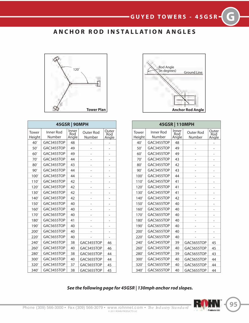
Phone (309) 566-3000 • Fax (309) 566-3079 • www.rohnnet.com • The Industry Standard
GG U Y E D T O W E R S - 4 5 G S R
95© 2011 ROHN PRODUCTS LLC
A N C H O R R O D I N S T A L L A T I O N A N G L E S
120o
Ground Line
Rod Angle(in degrees)
Tower
Height
40’
50’
60’
70’
80’
90’
100’
110’
120’
130’
140’
150’
160’
170’
180’
190’
200’
220’
240’
260’
280’
300’
320’
340’
Inner Rod
Number
GAC3455TOP
GAC3455TOP
GAC3455TOP
GAC3455TOP
GAC3455TOP
GAC3455TOP
GAC3455TOP
GAC3455TOP
GAC3455TOP
GAC3455TOP
GAC3455TOP
GAC3455TOP
GAC3455TOP
GAC5655TOP
GAC5655TOP
GAC5655TOP
GAC5655TOP
GAC5655TOP
GAC3455TOP
GAC3455TOP
GAC3455TOP
GAC3455TOP
GAC3455TOP
GAC3455TOP
InnerRod
Angle
48
49
49
44
43
44
44
42
42
42
42
40
40
40
41
40
40
40
38
40
38
40
37
38
45GSR | 90MPH
Outer Rod
Number
-
-
-
-
-
-
-
-
-
-
-
-
-
-
-
-
-
-
GAC3455TOP
GAC3455TOP
GAC5655TOP
GAC5655TOP
GAC5655TOP
GAC5655TOP
OuterRod
Angle
-
-
-
-
-
-
-
-
-
-
-
-
-
-
-
-
-
-
46
46
44
44
45
45
Tower
Height
40’
50’
60’
70’
80’
90’
100’
110’
120’
130’
140’
150’
160’
170’
180’
190’
200’
220’
240’
260’
280’
300’
320’
340’
Inner Rod
Number
GAC3455TOP
GAC3455TOP
GAC3455TOP
GAC3455TOP
GAC3455TOP
GAC3455TOP
GAC3455TOP
GAC3455TOP
GAC3455TOP
GAC3455TOP
GAC3455TOP
GAC5655TOP
GAC5655TOP
GAC5655TOP
GAC5655TOP
GAC5655TOP
GAC5655TOP
GAC5655TOP
GAC3455TOP
GAC3455TOP
GAC3455TOP
GAC3455TOP
GAC5655TOP
GAC5655TOP
InnerRod
Angle
48
49
49
43
42
43
44
41
41
41
42
40
40
40
40
40
40
40
39
40
39
40
40
40
45GSR | 110MPH
Outer Rod
Number
-
-
-
-
-
-
-
-
-
-
-
-
-
-
-
-
-
-
GAC5655TOP
GAC5655TOP
GAC5655TOP
GAC5655TOP
GAC5655TOP
GAC5655TOP
OuterRod
Angle
-
-
-
-
-
-
-
-
-
-
-
-
-
-
-
-
-
-
45
45
43
44
44
44
See the following page for 45GSR | 130mph anchor rod slopes.
Tower Plan Anchor Rod Angle

A N C H O R R O D I N S T A L L A T I O N A N G L E S
Phone (309) 566-3000 • Fax (309) 566-3079 • www.rohnnet.com • The Industry Standard
G G U Y E D T O W E R S - 4 5 G S R
96© 2011 ROHN PRODUCTS LLC
Tower
Height
40’
50’
60’
70’
80’
90’
100’
110’
120’
130’
140’
150’
160’
170’
180’
190’
200’
220’
240’
260’
280’
300’
320’
340’
Inner Rod
Number
GAC3455TOP
GAC3455TOP
GAC3455TOP
GAC3455TOP
GAC3455TOP
GAC3455TOP
GAC3455TOP
GAC5655TOP
GAC5655TOP
GAC5655TOP
GAC5655TOP
GAC5755TOP
GAC5755TOP
GAC5755TOP
GAC5755TOP
GAC5755TOP
GAC5755TOP
GAC5755TOP
GAC5655TOP
GAC5655TOP
GAC5755TOP
GAC5755TOP
GAC5755TOP
GAC5755TOP
InnerRod
Angle
48
48
45
42
42
43
43
40
40
41
41
39
38
39
39
37
38
38
40
41
38
39
37
38
45GSR | 130MPH
Outer Rod
Number
-
-
-
-
-
-
-
-
-
-
-
-
-
-
-
-
-
-
GAC5655TOP
GAC5655TOP
GAC5755TOP
GAC5755TOP
GAC5655TOP
GAC5655TOP
OuterRod
Angle
-
-
-
-
-
-
-
-
-
-
-
-
-
-
-
-
-
-
45
45
42
43
43
43
120o
Ground Line
Rod Angle(in degrees)
Tower Plan Anchor Rod Angle
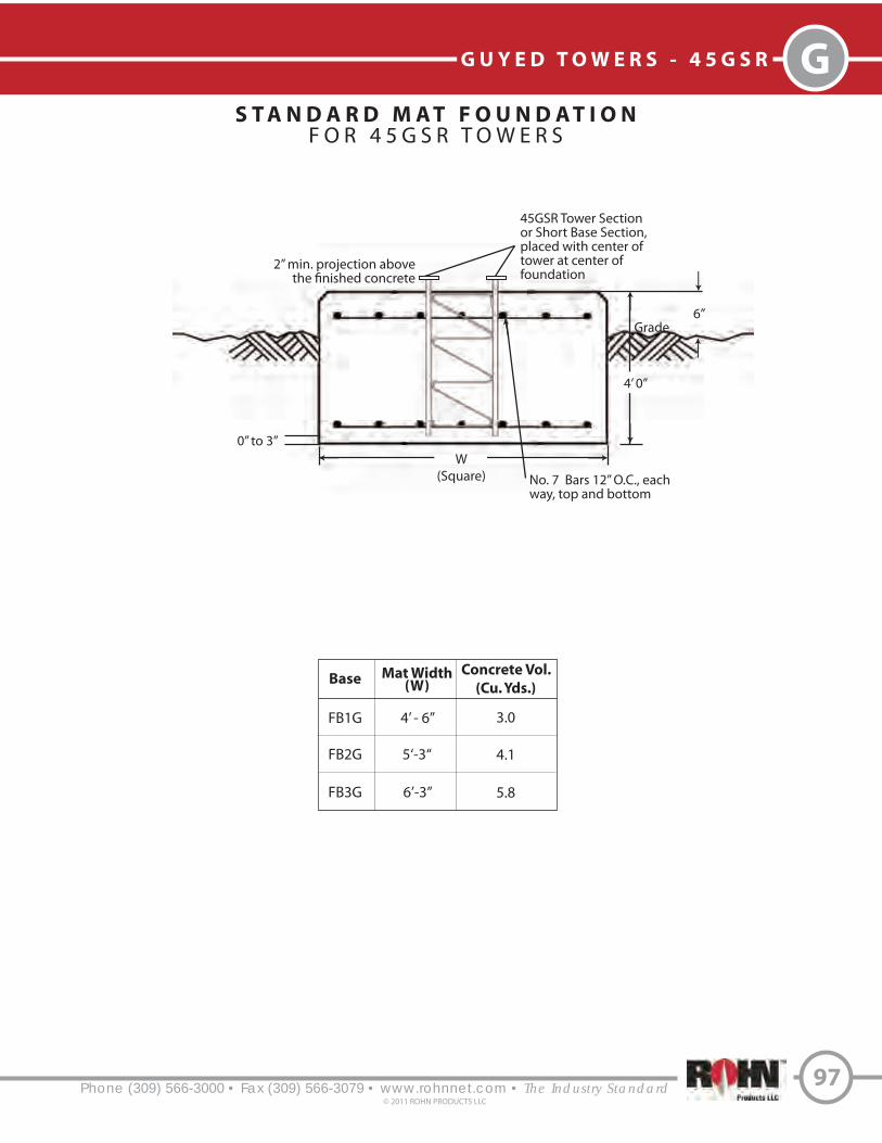
Phone (309) 566-3000 • Fax (309) 566-3079 • www.rohnnet.com • The Industry Standard
GG U Y E D T O W E R S - 4 5 G S R
97© 2011 ROHN PRODUCTS LLC
S T A N D A R D M A T F O U N D A T I O NF O R 4 5 G S R T OW E R S
Base
FB1G
FB2G
FB3G
Mat Width(W)
4’ - 6”
5‘-3“
6’-3”
Concrete Vol.
(Cu. Yds.)
3.0
4.1
5.8
Grade
W
(Square) No. 7 Bars 12” O.C., eachway, top and bottom
4’ 0”
2” min. projection abovethe !nished concrete
45GSR Tower Section or Short Base Section,placed with center of tower at center offoundation
0” to 3”
6”

Phone (309) 566-3000 • Fax (309) 566-3079 • www.rohnnet.com • The Industry Standard
G G U Y E D T O W E R S - 4 5 G S R
S T A N D A R D M E T E O R O L O G I C A L T O W E R S
98© 2011 ROHN PRODUCTS LLC
60MMET
4 Guy Elevations1 Fixed Base Foundation
1 Anchor Radius
ANSI/TIA-222-G110 MPH - 3 Second Gust (No Ice)
50 MPH - 3 Second Gust (3/4” Radial Ice)Structure Class II
Exposure Category CTopographic Category I
80MMET
5 Guy Elevations1 Fixed Base Foundation
1 Anchor Radius
ANSI/TIA-222-G110 MPH - 3 Second Gust (No Ice)
50 MPH - 3 Second Gust (3/4” Radial Ice)Structure Class II
Exposure Category CTopographic Category I
100MMET
6 Guy Elevations1 Fixed Base Foundation
2 Anchor Radii
ANSI/TIA-222-G110 MPH - 3 Second Gust (No Ice)
50 MPH - 3 Second Gust (3/4” Radial Ice)Structure Class II
Exposure Category CTopographic Category I
80 m
100 m
250’
198’
148’
98’
48’
190’
148‘
98’
48’
197’
262’
331’
318’
268’
218’
158’
98’
48’
Complete Kit Includes:
- Assembly and foundation drawings- All necessary tower sections- Tower short base- All guy wire and connectors- All guy anchors- Base and anchor grounding kits
60 m
EPA / WT.
(no ice)
9.00 sq. ft. / 200 lbs.
9.00 sq. ft. / 200 lbs.
9.00 sq. ft. / 200 lbs.
EPA / WT.
(3/4” radial ice)
25.00 sq. ft. / 600 lbs.
25.00 sq. ft. / 600 lbs.
25.00 sq. ft. / 600 lbs.
40 m
50 m
60 m
Boom
Height
EPA / WT.
(no ice)
9.00 sq. ft. / 200 lbs.
9.00 sq. ft. / 200 lbs.
9.00 sq. ft. / 200 lbs.
EPA / WT.
(3/4” radial ice)
25.00 sq. ft. / 600 lbs.
25.00 sq. ft. / 600 lbs.
25.00 sq. ft. / 600 lbs.
60 m
70 m
80 m
Boom
Height
EPA / WT.
(no ice)
9.00 sq. ft. / 200 lbs.
9.00 sq. ft. / 200 lbs.
9.00 sq. ft. / 200 lbs.
EPA / WT.
(3/4” radial ice)
25.00 sq. ft. / 600 lbs.
25.00 sq. ft. / 600 lbs.
25.00 sq. ft. / 600 lbs.
50 m
75 m
100 m
Boom
Height
Tower design assumes (1) elevator track over height of structure.

STANDARD SECTION
45GSR10 - 10’ Section45GSR20 - 20’ Section
14 1/2”
9 21/32”
16 3/4”
Double bracedsections provided
where required.
Optional WaveguideBrackets (KY2041A)
Phone (309) 566-3000 • Fax (309) 566-3079 • www.rohnnet.com • The Industry Standard
GG U Y E D T O W E R S - 4 5 G S R
S T A N D A R D 4 5 G S R
M E T E O R O L O G I C A L T O W E R
99© 2011 ROHN PRODUCTS LLC
1 1/4” O.D.Solid Round
7/16” or 5/8” O.D. Solid Bracing
156
210
106 / 264
TowerHeight
(m)
FB2G
FB3G
FB3G
BaseFoundation
No.
Guy Radius (ft.)120 separationo
AB4
AB5
AB2 / AB6
AnchorFoundation
No.
60
80
100
Refer to page 288 for anchor rod details.
FOR FOUNDATION INFORMATION, PLEASE SEE
PAGES 94 & 97. FOR GENERAL INSTALLATION
INFORMATION, PLEASE SEE PAGES 147-153.
4.3’ 45GSR SHORT BASE
45GSRSB
TO BE EMBEDDED IN CONCRETE.
1 1/4” O.D. Solid Round
7/16” O.D.Solid Bracing

Mixing copies of ROHN towers with ROHN towers is dangerous and voids all engineering and warranty data supplied by ROHN. Materials used by others are not the same quality and have not been tested or engineered by ROHN. MixingROHN tower sections with non-ROHN products may cause tower failure or injury.
CAUTION
Phone (309) 566-3000 • Fax (309) 566-3079 • www.rohnnet.com • The Industry Standard
G G U Y E D T O W E R S - 5 5 G
S T A N D A R D 5 5 G G U Y E D T O W E R
100© 2011 ROHN PRODUCTS LLC
The first. The original.ROHN 55G
Per Rev G requirements, any structure greater than 10’ requires a climber
safety device. Please see page 116 for ordering information.
REV. G
includes
REV. F &
GENERAL USE
The 55G lends itself to a wide variety of uses,
particularly where unusual wind loading and
height requirements exist. The 55G was designed
to provide excellent strength in heights up to
400’.
FEATURES
• Completely hot-dip galvanized after fabrication
• Built on a 17” equilateral triangle design
• High strength tubular legs joined by Zig-Zag®
cross members
• Each section contains all required nuts and bolts
shipped with section
• Continuous solid round steel bracing
55G

1 1/2” O.D.(11 GA.)
STANDARD SECTION
55G - 10’ Section
Phone (309) 566-3000 • Fax (309) 566-3079 • www.rohnnet.com • The Industry Standard
GG U Y E D T O W E R S - 5 5 G
S T A N D A R D 5 5 G G U Y E D T O W E R
S E C T I O N S
101
9 13/16”
7/16” O.D. Solid Bracing
© 2011 ROHN PRODUCTS LLC
17”
PARTS & ACCESSORIES PAGES 115-116GROUNDING INFORMATION PAGE 117FOUNDATION INFORMATION PAGES 117-120
QUICK REFERENCE14 3/4”
CONCRETE BASE PLATE
BPC55G*FOR USE WITH 3/4X12PP PIER PIN
EMBEDDED IN CONCRETE.
Additional base sections are available, please see page 115.
Optional double braced sections are available upon request.
Optional WaveguideBrackets (KY2041A)
* Towers mounted on these bases must be bracketed or guyed at all times. Temporary steel guying may also be necessary during installation and dismantling.
TOP PLATE
APL55GFOR MOUNTING BEACON OR LIGHTNING ROD.
TOP PLATE BOLTS TO THE TOP OF A STANDARD SECTION.

EPA (SQ. FT.) For Exposure B, Revision G
EPA (SQ. FT.) For Exposure C, Revision G
EPA (SQ. FT.), Revision F
P/N 55G90R100
117’
90’
85’
42’
80’
3/16” EHS(399#)
30.4
32.0
39.0
P/N 55G90R100
Tower ModelWindspeed (Rev. G) ROHN Tower
Tower Height (ft.)
EPA= Effective Projected Area
Phone (309) 566-3000 • Fax (309) 566-3079 • www.rohnnet.com • The Industry Standard
G G U Y E D T O W E R S - 5 5 G
B U Y E R S G U I D ES T A N D A R D D E S I G N S - 5 5 G
9 0 M P H R E V . G [ 3 S E C O N D G U S T ]7 0 M P H R E V . F [ F A S T E S T M I L E ]
102© 2011 ROHN PRODUCTS LLC
1/4” EHS(665#)
Guy Initial Tension
This document is to serve as a guide for sizing and purchasing the 55G tower. Tower and foundation installations should be performed by qualified and experienced personnel using assembly drawings provided with each tower.
DESIGN NOTES:
1. Tower designs are in accordance with ANSI/TIA-222-F and ANSI/TIA-222-G, Class I Structures, Topographic Category 1. 2. Design assumes towers are installed on level ground. Lower EPA values will apply for roof mounted towers or for sites located on unusual terrain. 3. Designs assume two 1/2” diameter lines on each tower face. 4. Anchor radius is from tower base to intersection of anchor rod with ground. 5. Guy chord lengths shown are based on level ground. Initial tensions for guys are shown in ( ) in pounds at 60º Fahrenheit. 6. Antenna and mounts are assumed symmetrically placed at the tower top.
PARTS LIST NOTES:
1. Items listed are required for complete guyed towers. 2. Base and anchor foundations listed refer to standard foundation designations. 3. Guys provided with each standard tower are based on level ground conditions with an additional 6% length. 4. Rev G anchor grounding (AGK1GGX) and base grounding (BGK2GGX) are included with the tower material. 5. Assembly drawings and a safety package (P/N: ACWS) are included with each tower. 6. Parts lists are subject to change based on availability or revised design criteria.
FOR FOUNDATION INFORMATION, PLEASE SEE PAGES 117-120.
FOR GENERAL INSTALLATION INFORMATION, PLEASE SEE PAGES 147-153.
Design Criteria

S T A N D A R D D E S I G N - 5 5 G
9 0 M P H R E V . G , 7 0 M P H R E V . F
Phone (309) 566-3000 • Fax (309) 566-3079 • www.rohnnet.com • The Industry Standard
GG U Y E D T O W E R S - 5 5 G
103© 2011 ROHN PRODUCTS LLC
P/N: 55G90R120
120’ TOWER
105’
37.0 29.3OR
142’
96’
3/16” EHS(399#)
122’
75’
35’ 102’
1/4” EHS(665#)
P/N: 55G90R100
100’ TOWER
85’
39.0 30.4OR
117’
80’
1/4” EHS(665#)
90’42’
3/16” EHS(399#)
P/N: 55G90R110
110’ TOWER
95’
37.9 29.8OR
129’
88’
1/4” EHS(665#)
100’47’
3/16” EHS(399#)
P/N: 55G90R130
130’ TOWER
115’
36.1 28.7OR
155’
104’
3/16” EHS(399#)
129’
76’
38’ 111’
1/4” EHS(665#)
P/N: 55G90R140
140’ TOWER
125’
35.4 28.3OR
168’
112’
3/16” EHS(399#)
139’
83’
41’ 119’
1/4” EHS(665#)
TOWER PARTS
INCLUDED
GUYS &
CONNECTIONS
INCLUDED
ANCHORS &
GROUNDING
INCLUDED
55G BPC55G APL55G GA55GD
3/16EHS1/4EHS BG2142 BG2144 5/16THH
GAC3455TOP AGK1GGX BGK2GGX
10 1 1 2
300’ 375’ 6 6 6
3 1 3
100’ ROHN 55G
Al l par ts shown in
table are inc luded
when order ing
Par t No: 55G90R100
FDNS
BASE ANCHOR
3/8THH
6 6
1/2TBE&J
TOWER PARTS
INCLUDED
GUYS &
CONNECTIONS
INCLUDED
ANCHORS &
GROUNDING
INCLUDED
55G BPC55G APL55G GA55GD
3/16EHS1/4EHS BG2142 BG2144 5/16THH
AGK1GGX BGK2GGX
11 1 1 2
325’ 425’ 6 6 6
3 1 3
110’ ROHN 55G
Al l par ts shown in
table are inc luded
when order ing
Par t No: 55G90R110
FDNS
BASE ANCHOR
3/8THH
6 6
1/2TBE&J
TOWER PARTS
INCLUDED
GUYS &
CONNECTIONS
INCLUDED
ANCHORS &
GROUNDING
INCLUDED
55G BPC55G APL55G GA55GD
3/16EHS1/4EHS BG2142 BG2144 5/16THH
AGK1GGX BGK2GGX
12 1 1 3
725’ 475’ 12 6 12
3 1 3
120’ ROHN 55G
Al l par ts shown in
table are inc luded
when order ing
Par t No: 55G90R120
FDNS
BASE ANCHOR
3/8THH
6 9
1/2TBE&J
TOWER PARTS
INCLUDED
GUYS &
CONNECTIONS
INCLUDED
ANCHORS &
GROUNDING
INCLUDED
55G BPC55G APL55G GA55GD
3/16EHS1/4EHS BG2142 BG2144 5/16THH
AGK1GGX BGK2GGX
13 1 1 3
775’ 500’ 12 6 12
3 1 3
130’ ROHN 55G
Al l par ts shown in
table are inc luded
when order ing
Par t No: 55G90R130
FDNS
BASE ANCHOR
3/8THH
6 9
1/2TBE&J
TOWER PARTS
INCLUDED
GUYS &
CONNECTIONS
INCLUDED
ANCHORS &
GROUNDING
INCLUDED
55G BPC55G APL55G GA55GD
3/16EHS1/4EHS BG2142 BG2144 5/16THH
AGK1GGX BGK2GGX
14 1 1 3
825’ 550’ 12 6 12
3 1 3
140’ ROHN 55G
Al l par ts shown in
table are inc luded
when order ing
Par t No: 55G90R140
FDNS
BASE ANCHOR
3/8THH
6 9
1/2TBE&J
CPC.5/.75
3
TBSAFETY
3
CPC.5/.75
3
TBSAFETY
3
TBSAFETY
3
CPC.5/.75
3
TBSAFETY
3
CPC.5/.75
3
TBSAFETY
3
CPC.5/.75
3
CB1G AB2
CB1G AB2
CB1G AB2
CB1G AB2
CB1G AB2
32.0
31.2
30.4
29.8
29.0
GAC3455TOP
GAC3455TOP
GAC3455TOP
GAC3455TOP
3/4x12PP
1
3/4x12PP
1
3/4x12PP
1
3/4x12PP
1
3/4x12PP
1

Phone (309) 566-3000 • Fax (309) 566-3079 • www.rohnnet.com • The Industry Standard
G G U Y E D T O W E R S - 5 5 G
S T A N D A R D D E S I G N - 5 5 G
9 0 M P H R E V . G , 7 0 M P H R E V . F
104© 2011 ROHN PRODUCTS LLC
P/N: 55G90R150
150’ TOWER
135’
34.7 27.9OR
181’
120’
3/16” EHS(399#)
151’
92’
45’ 128’
1/4” EHS(665#)
P/N: 55G90R160
160’ TOWER
145’
33.9 27.5OR
193’
128’
3/16” EHS(399#)
160’
96’
48’ 137’
1/4” EHS(665#)
P/N: 55G90R170
170’ TOWER
155’
33.3 27.2OR
206’
136’
178’
115’
37’ 141’
75’155’ 3/16” EHS
(399#)
1/4” EHS(665#)
P/N: 55G90R180
180’ TOWER
165’
32.8 26.8OR
219’
144’
190’
124’
42’ 150’
83’166’ 3/16” EHS
(399#)
1/4” EHS(665#)
P/N: 55G90R190
190’ TOWER
175’
32.4 26.5OR
232’
152’
201’
131’
43’ 158’
87’175’ 3/16” EHS
(399#)
5/16” EHS(1,120#)
TOWER PARTS
INCLUDED
GUYS &
CONNECTIONS
INCLUDED
ANCHORS &
GROUNDING
INCLUDED
55G BPC55G APL55G GA55GD
3/16EHS1/4EHS BG2142 BG2144 5/16THH
AGK1GGX BGK2GGX
15 1 1 3
900’ 600’ 12 6 12
3 1 3
150’ ROHN 55G
Al l par ts shown in
table are inc luded
when order ing
Par t No: 55G90R150
FDNS
BASE ANCHOR
3/8THH
6 9
1/2TBE&J
TOWER PARTS
INCLUDED
GUYS &
CONNECTIONS
INCLUDED
ANCHORS &
GROUNDING
INCLUDED
55G BPC55G APL55G GA55GD
3/16EHS1/4EHS BG2142 BG2144 5/16THH
AGK1GGX BGK2GGX
16 1 1 3
950’ 625’ 12 6 12
3 1 3
160’ ROHN 55G
Al l par ts shown in
table are inc luded
when order ing
Par t No: 55G90R160
FDNS
BASE ANCHOR
3/8THH
6 9
1/2TBE&J
TOWER PARTS
INCLUDED
GUYS &
CONNECTIONS
INCLUDED
ANCHORS &
GROUNDING
INCLUDED
55G BPC55G APL55G GA55GD
3/16EHS1/4EHS BG2142 BG2144 5/16THH
GAC3455TOP AGK1GGX BGK2GGX
17 1 1 4
1525’ 675’ 18 6 18
3 1 3
170’ ROHN 55G
Al l par ts shown in
table are inc luded
when order ing
Par t No: 55G90R170
FDNS
BASE ANCHOR
3/8THH
6 12
1/2TBE&J
TOWER PARTS
INCLUDED
GUYS &
CONNECTIONS
INCLUDED
ANCHORS &
GROUNDING
INCLUDED
55G BPC55G APL55G GA55GD
3/16EHS1/4EHS BG2142 BG2144 5/16THH
GAC3455TOP AGK1GGX BGK2GGX
18 1 1 4
1625’ 700’ 18 6 18
3 1 3
180’ ROHN 55G
Al l par ts shown in
table are inc luded
when order ing
Par t No: 55G90R180
FDNS
BASE ANCHOR
3/8THH
6 12
1/2TBE&J
TOWER PARTS
INCLUDED
GUYS &
CONNECTIONS
INCLUDED
ANCHORS &
GROUNDING
INCLUDED
55G BPC55G APL55G GA55GD
3/16EHS142265 BG2142 BG2146 5/16THH
GAC5655TOP AGK1GGX BGK2GGX
19 1 1 4
1700’ 750’ 18 6 18
3 1 3
190’ ROHN 55G
Al l par ts shown in
table are inc luded
when order ing
Par t No: 55G90R190
FDNS
BASE ANCHOR
7/16THH
6 12
5/8TBE&J
CPC.5/.75
3
TBSAFETY
3
CPC1/1.25
3
TBSAFETY
3
CPC.5/.75
3
TBSAFETY
3
CPC.5/.75
3
TBSAFETY
3
CPC.5/.75
3
TBSAFETY
3
CB2G AB2
CB2G AB2
CB2G AB2
CB2G AB2
CB2G AB3
28.6
28.0
27.4
27.0
26.6
GAC3455TOP
GAC3455TOP 3/4x12PP
1
3/4x12PP
1
3/4x12PP
1
3/4x12PP
1
3/4x12PP
1
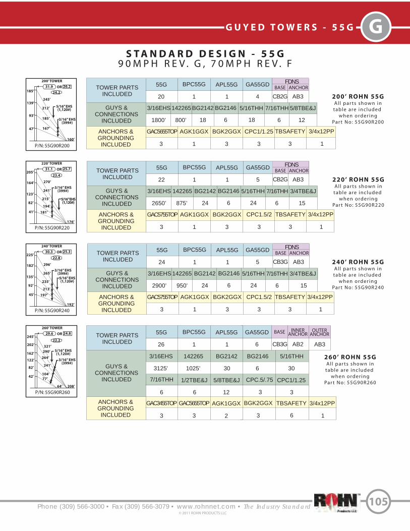
Phone (309) 566-3000 • Fax (309) 566-3079 • www.rohnnet.com • The Industry Standard
GG U Y E D T O W E R S - 5 5 G
S T A N D A R D D E S I G N - 5 5 G
9 0 M P H R E V . G , 7 0 M P H R E V . F
105© 2011 ROHN PRODUCTS LLC
P/N: 55G90R200
200’ TOWER
185’
31.9 26.2OR
245’
160’
212’
139’
47’ 167’
93’185’ 3/16” EHS
(399#)
TOWER PARTS
INCLUDED
GUYS &
CONNECTIONS
INCLUDED
ANCHORS &
GROUNDING
INCLUDED
55G BPC55G APL55G GA55GD
3/16EHS 142265 BG2142 BG2146 5/16THH
GAC5655TOP AGK1GGX BGK2GGX
20 1 1 4
1800’ 800’ 18 6 18
3 1 3
200’ ROHN 55G
Al l par ts shown intable are inc luded
when order ingPar t No: 55G90R200
FDNS
BASE ANCHOR
7/16THH
6 12
5/8TBE&J
TOWER PARTS
INCLUDED
GUYS &
CONNECTIONS
INCLUDED
ANCHORS &
GROUNDING
INCLUDED
55G BPC55G APL55G GA55GD
3/16EHS 142265 BG2142 BG2146 5/16THH
GAC5755TOP AGK1GGX BGK2GGX
22 1 1 5
2650’ 875’ 24 6 24
3 1 3
220’ ROHN 55G
Al l par ts shown intable are inc luded
when order ingPar t No: 55G90R220
FDNS
BASE ANCHOR
7/16THH
6 15
3/4TBE&J
P/N: 55G90R220
220’ TOWER
205’31.1 25.7OR
270’
176’
241’
164’
41’
123’
215’
3/16” EHS(399#)
194’
181’
82’
5/16” EHS(1,120#)
TOWER PARTS
INCLUDED
GUYS &
CONNECTIONS
INCLUDED
ANCHORS &
GROUNDING
INCLUDED
55G BPC55G APL55G GA55GD
3/16EHS 142265 BG2142 BG2146 5/16THH
AGK1GGX BGK2GGX
24 1 1 5
2900’ 950’ 24 6 24
3 1 3
240’ ROHN 55G
Al l par ts shown intable are inc luded
when order ingPar t No: 55G90R240
FDNS
BASE ANCHOR
7/16THH
6 15
3/4TBE&J
P/N: 55G90R240
240’ TOWER
225’30.3 25.3OR
296’
192’
265’
182’
45’
135’
235’
3/16” EHS(399#)
213’
197’
92’
5/16” EHS(1,120#)
CPC1.5/2
3
TBSAFETY
3
CPC1.5/2
3
TBSAFETY
3
CPC1/1.25
3
TBSAFETY
3
260’ ROHN 55G
Al l par ts shown intable are inc luded
when order ingPar t No: 55G90R260
P/N: 55G90R260
260’ TOWER
245’29.6 24.8OR
321’
208’
5/16” EHS(1,120#)
202’
42’
162’
122’
77’
104’
3/16” EHS(399#)
64’
82’241’
264’
290’
TOWER PARTS
INCLUDED
GUYS &
CONNECTIONS
INCLUDED
ANCHORS &
GROUNDING
INCLUDED
55G BPC55G APL55G GA55GD
GAC5655TOP BGK2GGX
CPC.5/.75
26 1 1 6
3
3 3
3/16EHS
3125’
7/16THH
6
142265
1025’
BG2142
30
1/2TBE&J
6
BG2146
6
5/8TBE&J
12
5/16THH
30
CPC1/1.25
3
AGK1GGX
23
CB2G AB3
CB2G AB3
CB3G AB3
BASE INNERANCHOR
CB3G
OUTERANCHOR
AB3AB2
24.2
23.4
22.8
22.2
5/16” EHS(1,120#)
GAC5755TOP
GAC3455TOP TBSAFETY
6
3/4x12PP
1
3/4x12PP
1
3/4x12PP
1
3/4x12PP
1

Phone (309) 566-3000 • Fax (309) 566-3079 • www.rohnnet.com • The Industry Standard
G G U Y E D T O W E R S - 5 5 G
S T A N D A R D D E S I G N - 5 5 G
9 0 M P H R E V . G , 7 0 M P H R E V . F
106© 2011 ROHN PRODUCTS LLC
280’ ROHN 55G
Al l par ts shown intable are inc luded
when order ingPar t No: 55G90R280
P/N: 55G90R280
280’ TOWER
265’29.0 24.4OR
347’
224’
5/16” EHS(1,120#)
222’
43’
175’
132’
82’
110’
3/16” EHS(399#)
70’
85’260’
284’
315’
300’ ROHN 55G
Al l par ts shown intable are inc luded
when order ingPar t No: 55G90R300
P/N: 55G90R300
300’ TOWER
285’28.4 24.1OR
373’
240’
5/16” EHS(1,120#)
242’
42’
202’
162’ 3/16” EHS(399#)
100’
82’
290’
314’
341’
108’
129’
158’
122’
320’ ROHN 55G
All parts shown intable are included
when orderingPart No: 55G90R320
P/N: 55G90R320
320’ TOWER
305’27.9 23.8OR
398’
256’
5/16” EHS(1,120#)
262’
42’
215’
172’ 3/16” EHS(399#)
100’
82’
308’
334’
366’
108’
129’
160’
125’
340’ ROHN 55G
All parts shown intable are included
when orderingPart No: 55G90R340
P/N: 55G90R340
340’ TOWER
325’27.4 23.5OR
424’
272’
5/16” EHS(1,120#)
282’
42’
202’
162’ 3/16” EHS(399#)
96’
82’
317’
364’
105’
126’
155’
122’
339’
392’242’
21.8
21.2
20.8
20.4
TOWER PARTS
INCLUDED
GUYS &
CONNECTIONS
INCLUDED
ANCHORS &
GROUNDING
INCLUDED
55G BPC55G APL55G GA55GD
GAC5655TOP BGK2GGX
CPC.5/.75
28 1 1 6
3
3 3
3/16EHS
3350
7/16THH
6
142265
1125’
BG2142
30
1/2TBE&J
6
BG2146
6
5/8TBE&J
12
5/16THH
30
CPC1/1.25
3
AGK1GGX
23
BASE INNERANCHOR
CB4G
OUTERANCHOR
AB3AB2
TOWER PARTS
INCLUDED
GUYS &
CONNECTIONS
INCLUDED
ANCHORS &
GROUNDING
INCLUDED
55G BPC55G APL55G GA55GD
BGK2GGX
CPC.5/.75
30 1 1 7
3
3 3
3/16EHS
4275’
7/16THH
6
142265
1200’
BG2142
36
1/2TBE&J
9
BG2146
6
5/8TBE&J
12
5/16THH
36
TBSAFETY
6
AGK1GGX
23
BASE INNERANCHOR
CB4G
OUTERANCHOR
AB3AB2
TOWER PARTS
INCLUDED
GUYS &
CONNECTIONS
INCLUDED
ANCHORS &
GROUNDING
INCLUDED
55G BPC55G APL55G GA55GD
BGK2GGX CPC.5/.75
32 1 1 7
33 3
3/16EHS
2250’
7/16THH
6
1/4EHS
2250’
BG2142
24
1/2TBE&J
9
BG2146
6
5/8TBE&J
12
BG2144
12
TBSAFETY
6
AGK1GGX
23
BASE INNERANCHOR
CB4G
OUTERANCHOR
AB3AB2
TOWER PARTS
INCLUDED
GUYS &
CONNECTIONS
INCLUDED
ANCHORS &
GROUNDING
INCLUDED
55G BPC55G APL55G GA55GD
BGK2GGX CPC.5/.75
34 1 1 8
33 3
3/16EHS
3325’
7/16THH
6
142265
1350’
BG2142
30
1/2TBE&J
9
BG2146
6
5/8TBE&J
15
5/16THH
30
TBSAFETY
6
AGK1GGX
23
BASE INNERANCHOR
CB4G
OUTERANCHOR
AB3AB2
142265
1275’1/4” EHS(665#)
1/4” EHS(665#)
1/4EHS
2425’
GAC3455TOP
GAC5655TOPGAC3455TOP
GAC5655TOPGAC3455TOP
GAC5655TOPGAC3455TOP
TBSAFETY
6
CPC1/1.25
3
3/8THH
12
5/16THH
24
CPC1/1.25
3
CPC1/1.25
3
3/8THH
12
BG2144
12
3/4x12PP
1
3/4x12PP
1
3/4x12PP
1
3/4x12PP
1

Phone (309) 566-3000 • Fax (309) 566-3079 • www.rohnnet.com • The Industry Standard
GG U Y E D T O W E R S - 5 5 G
S T A N D A R D D E S I G N - 5 5 G
9 0 M P H R E V . G , 7 0 M P H R E V . F
107© 2011 ROHN PRODUCTS LLC
360’ ROHN 55G
All parts shown intable are included
when orderingPart No: 55G90R360
P/N: 55G90R360
360’ TOWER
345’27.0 23.2OR
449’
288’
5/16” EHS(1,120#)
302’
42’
212’
168’ 3/16” EHS(399#)
100’
84’
333’
385’
108’
131’
161’
126’
358’
417’255’
1/4” EHS(665#)
380’ ROHN 55G
All parts shown intable are included
when orderingPart No: 55G90R380
P/N: 55G90R380
380’ TOWER
365’26.6 22.9OR
475’
304’
5/16” EHS(1,120#)
319’
45’
227’
181’ 3/16” EHS(399#)
110’
92’
354’
409’
119’
143’
174’
135’
379’
441’273’
1/4” EHS(665#)
P/N: 55G90R400
400’ TOWER
385’26.1 22.7OR
501’
320’
5/16” EHS(1,120#)
335’
46’
235’
185’ 3/16” EHS(399#)
120’
92’
370’
429’
129’
151’
183’
138’
397’
463’285’
1/4” EHS(665#)
20.0
19.6
19.2
TOWER PARTS
INCLUDED
GUYS &
CONNECTIONS
INCLUDED
ANCHORS &
GROUNDING
INCLUDED
55G BPC55G APL55G GA55GD
BGK2GGX CPC.5/.75
36 1 1 8
33 3
3/16EHS
3475’
5/16THH
30
1/4EHS
2575’
3/8THH
12
142265
1450’
7/16THH
6
BG2142
30
BG2144
12
1/2TBE&J
9
AGK1GGX
23
APL1258UM
2
BG2146
6
5/8TBE&J
15
BASE INNERANCHOR
CB5G
OUTERANCHOR
AB4AB2
TOWER PARTS
INCLUDED
GUYS &
CONNECTIONS
INCLUDED
ANCHORS &
GROUNDING
INCLUDED
55G BPC55G APL55G GA55GD
BGK2GGX CPC.5/.75
38 1 1 8
33
3/16EHS
3175’
5/16THH
24
1/4EHS
3275’
3/8THH
18
142265
1525’
7/16THH
6
BG2142
24
BG2144
18
15
AGK1GGX
23
APL1258UM
2
BG2146
6
5/8TBE&J
BASE INNERANCHOR
CB5G
OUTERANCHOR
AB4AB2
400’ ROHN 55G
All parts shown intable are included
when orderingPart No: 55G90R400
TOWER PARTS
INCLUDED
GUYS &
CONNECTIONS
INCLUDED
ANCHORS &
GROUNDING
INCLUDED
55G BPC55G APL55G GA55GD
BGK2GGX CPC.5/.75
40 1 1 8
33
3/16EHS
2075’
5/16THH
18
1/4EHS
4700’
3/8THH
24
142265
1600’
7/16THH
6
BG2142
18
BG2144
24
9
AGK1GGX
2
APL1258UM
2
BG2146
6
1/2TBE&J
BASE INNERANCHOR
CB5G
OUTERANCHOR
AB4AB2
TBSAFETY
6
1/2TBE&J
9
TBSAFETY
6
GAC5655TOPGAC3455TOP
GAC5655TOPGAC3455TOP
3
3
GAC5655TOPGAC3455TOP
3
TBSAFETY
6
15
5/8TBE&J
CPC1/1.25
3
CPC1/1.25
3
CPC1/1.25
3
3/4x12PP
1
3/4x12PP
1

Phone (309) 566-3000 • Fax (309) 566-3079 • www.rohnnet.com • The Industry Standard
G G U Y E D T O W E R S - 5 5 G
S T A N D A R D D E S I G N - 5 5 G
1 1 0 M P H R E V . G , 9 0 M P H R E V . F
108© 2011 ROHN PRODUCTS LLC
P/N: 55G110R120
120’ TOWER
115’
24.8 19.6OR
150’
96’
3/16” EHS(399#)
123’
77’
38’ 103’
1/4” EHS(665#)
P/N: 55G110R130
130’ TOWER
125’
24.2 19.2OR
163’
104’
3/16” EHS(399#)
133’
83’
42’ 112’
1/4” EHS(665#)
TOWER PARTS
INCLUDED
GUYS &
CONNECTIONS
INCLUDED
ANCHORS &
GROUNDING
INCLUDED
55G BPC55G APL55G GA55GD
3/16EHS1/4EHS BG2142 BG2144 5/16THH
GAC3455TOP AGK1GGX BGK2GGX
10 1 1 3
600’ 400’ 12 6 12
3 1 3
100’ ROHN 55G
Al l par ts shown in
table are inc luded
when order ing
Par t No: 55G110R100
FDNS
BASE ANCHOR
3/8THH
6 9
1/2TBE&J
3
TBSAFETY
3P/N: 55G110R100
100’ TOWER
95’
26.1 20.4OR
124’
80’
3/16” EHS(399#)
102’
63’
33’ 87’
1/4” EHS(665#)
P/N: 55G110R110
110’ TOWER
105’
25.4 19.9OR
137’
88’
3/16” EHS(399#)
114’
72’
35’ 95’
1/4” EHS(665#)
P/N: 55G110R140
140’ TOWER
135’
23.6 18.9OR
175’
112’
151’
101’
34’ 117’
67’131’ 3/16” EHS
(399#)
1/4” EHS(665#)
TOWER PARTS
INCLUDED
GUYS &
CONNECTIONS
INCLUDED
ANCHORS &
GROUNDING
INCLUDED
55G BPC55G APL55G GA55GD
3/16EHS1/4EHS BG2142 BG2144 5/16THH
GAC3455TOP AGK1GGX BGK2GGX
11 1 1 3
675’ 450’ 12 6 12
3 1 3
110’ ROHN 55G
Al l par ts shown in
table are inc luded
when order ing
Par t No: 55G110R110
FDNS
BASE ANCHOR
3/8THH
6 9
1/2TBE&J
3
TBSAFETY
3
TOWER PARTS
INCLUDED
GUYS &
CONNECTIONS
INCLUDED
ANCHORS &
GROUNDING
INCLUDED
55G BPC55G APL55G GA55GD
3/16EHS1/4EHS BG2142 BG2144 5/16THH
GAC3455TOP AGK1GGX BGK2GGX
12 1 1 3
725’ 500’ 12 6 12
3 1 3
120’ ROHN 55G
Al l par ts shown in
table are inc luded
when order ing
Par t No: 55G110R120
FDNS
BASE ANCHOR
3/8THH
6 9
1/2TBE&J
3
TBSAFETY
3
TOWER PARTS
INCLUDED
GUYS &
CONNECTIONS
INCLUDED
ANCHORS &
GROUNDING
INCLUDED
55G BPC55G APL55G GA55GD
3/16EHS1/4EHS BG2142 BG2144 5/16THH
GAC3455TOP AGK1GGX BGK2GGX
13 1 1 3
800’ 525’ 12 6 12
3 1 3
130’ ROHN 55G
Al l par ts shown in
table are inc luded
when order ing
Par t No: 55G110R130
FDNS
BASE ANCHOR
3/8THH
6 9
1/2TBE&J
3
TBSAFETY
3
TOWER PARTS
INCLUDED
GUYS &
CONNECTIONS
INCLUDED
ANCHORS &
GROUNDING
INCLUDED
55G BPC55G APL55G GA55GD
3/16EHS1/4EHS BG2142 BG2144 5/16THH
GAC3455TOP AGK1GGX BGK2GGX
14 1 1 4
1275’ 575’ 18 6 18
3 1 3
140’ ROHN 55G
Al l par ts shown in
table are inc luded
when order ing
Par t No: 55G110R140
FDNS
BASE ANCHOR
3/8THH
6 12
1/2TBE&J
3
TBSAFETY
3
CB1G AB2
CB1G AB2
CB2G AB2
CB2G AB2
CB2G AB2
19.2
18.6
18.2
17.8
17.2
CPC.5/.75
CPC.5/.75
CPC.5/.75
CPC.5/.75
CPC.5/.75 3/4x12PP
1
3/4x12PP
1
3/4x12PP
1
3/4x12PP
1
3/4x12PP
1

S T A N D A R D D E S I G N - 5 5 G
1 1 0 M P H R E V . G , 9 0 M P H R E V . F
Phone (309) 566-3000 • Fax (309) 566-3079 • www.rohnnet.com • The Industry Standard
GG U Y E D T O W E R S - 5 5 G
109© 2011 ROHN PRODUCTS LLC
P/N: 55G110R150
150’ TOWER
145’
23.2 18.7OR
188’
120’
161’
108’
36’ 125’
72’140’ 3/16” EHS
(399#)
1/4” EHS(665#)
TOWER PARTS
INCLUDED
GUYS &
CONNECTIONS
INCLUDED
ANCHORS &
GROUNDING
INCLUDED
55G BPC55G APL55G GA55GD
3/16EHS1/4EHS BG2142 BG2144 5/16THH
GAC5655TOP AGK1GGX BGK2GGX
15 1 1 4
1375’ 600’ 18 6 18
3 1 3
150’ ROHN 55G
Al l par ts shown in
table are inc luded
when order ing
Par t No: 55G110R150
FDNS
BASE ANCHOR
3/8THH
6 12
5/8TBE&J
3
TBSAFETY
3
P/N: 55G110R180
180’ TOWER
175’22.0 18.0OR
227’
144’
202’
142’
35’
105’
178’
3/16” EHS(399#)
161’
148’
72’
1/4” EHS(665#)
P/N: 55G110R160
160’ TOWER
155’
22.8 18.4OR
201’
128’
173’
116’
39’ 134’
78’150’ 3/16” EHS
(399#)
5/16” EHS(1,120#)
P/N: 55G110R170
170’ TOWER
165’
22.4 18.2OR
214’
136’
184’
124’
41’ 142’
83’159’ 3/16” EHS
(399#)
1/4” EHS(665#)
TOWER PARTS
INCLUDED
GUYS &
CONNECTIONS
INCLUDED
ANCHORS &
GROUNDING
INCLUDED
55G BPC55G APL55G GA55GD
3/16EHS1/4EHS BG2142 BG2144 5/16THH
GAC5655TOP AGK1GGX BGK2GGX
17 1 1 4
975’ 1275’ 12 12 12
3 1 3
170’ ROHN 55G
Al l par ts shown in
table are inc luded
when order ing
Par t No: 55G110R170
FDNS
BASE ANCHOR
3/8THH
12 12
5/8TBE&J
3
TBSAFETY
3
P/N: 55G110R190
190’ TOWER
185’21.7 17.8OR
239’
152’
212’
148’
37’
111’
188’
3/16” EHS(399#)
169’
156’
74’
5/16” EHS(1,120#)
1/4” EHS(665#)
TOWER PARTS
INCLUDED
GUYS &
CONNECTIONS
INCLUDED
ANCHORS &
GROUNDING
INCLUDED
55G BPC55G APL55G GA55GD
3/16EHS 142265 BG2142 BG2146 5/16THH
GAC5655TOP AGK1GGX BGK2GGX
16 1 1 4
1475’ 650’ 18 6 18
3 1 3
160’ ROHN 55G
Al l par ts shown in
table are inc luded
when order ing
Par t No: 55G110R160
FDNS
BASE ANCHOR
7/16THH
6 12
5/8TBE&J
3
TBSAFETY
3
TOWER PARTS
INCLUDED
GUYS &
CONNECTIONS
INCLUDED
ANCHORS &
GROUNDING
INCLUDED
55G BPC55G APL55G GA55GD
3/16EHS1/4EHS BG2142 BG2144 5/16THH
GAC5655TOP AGK1GGX BGK2GGX
18 1 1 5
1550’ 1375’ 18 12 18
3 1 3
180’ ROHN 55G
Al l par ts shown in
table are inc luded
when order ing
Par t No: 55G110R180
FDNS
BASE ANCHOR
3/8THH
12 15
5/8TBE&J
3
TBSAFETY
3
190’ ROHN 55G
Al l par ts shown in
table are inc luded
when order ing
Par t No: 55G110R190
TOWER PARTS
INCLUDED
GUYS &
CONNECTIONS
INCLUDED
ANCHORS &
GROUNDING
INCLUDED
55G BPC55G APL55G GA55GD
BGK2GGX
19 1 1 5
33
FDNS
BASE ANCHOR
3/16EHS
1650’
5/16THH
18
1/4EHS
675’
3/8THH
6
142265
775’
7/16THH
6
BG2142
18
5/8TBE&J
15
BG2144
6
AGK1GGX
1
GAC5655TOP
3
BG2146
6
TBSAFETY
3
CB2G AB3
CB2G AB3
CB2G AB3
CB3G AB3
CB3G AB3
15.6
15.8
16.2
16.4
16.8
CPC1/1.25
CPC1/1.25
CPC1/1.25
CPC1/1.25
CPC1/1.25 3/4x12PP
1
3/4x12PP
1
3/4x12PP
1
3/4x12PP
1
3/4x12PP
1

Phone (309) 566-3000 • Fax (309) 566-3079 • www.rohnnet.com • The Industry Standard
G G U Y E D T O W E R S - 5 5 G
S T A N D A R D D E S I G N - 5 5 G
1 1 0 M P H R E V . G , 9 0 M P H R E V . F
110© 2011 ROHN PRODUCTS LLC
P/N: 55G110R200
200’ TOWER
195’21.4 17.6OR
252’
160’
223’
156’
39’
117’
198’
3/16” EHS(399#)
178’
165’
78’
5/16” EHS(1,120#)
1/4” EHS(665#)
200’ ROHN 55G
All parts shown intable are included
when orderingPart No: 55G110R200
TOWER PARTS
INCLUDED
GUYS &
CONNECTIONS
INCLUDED
ANCHORS &
GROUNDING
INCLUDED
55G BPC55G APL55G GA55GD
BGK2GGX
20 1 1 5
33
FDNS
BASE ANCHOR
3/16EHS
1750’
5/16THH
18
1/4EHS
725’
3/8THH
6
142265
825’
7/16THH
6
BG2142
18
BG2144
6
AGK1GGX
1
GAC5655TOP
3
BG2146
6
5/8TBE&J
15
TBSAFETY
3
220’ ROHN 55G
All parts shown intable are included
when orderingPart No: 55G110R220
P/N: 55G110R220
220’ TOWER
215’20.8 17.2OR
278’
176’
5/16” EHS(1,120#)
182’
36’
145’
112’
70’
94’
3/16” EHS(399#)
60’
73’209’
228’
253’
1/4” EHS(665#)
TOWER PARTS
INCLUDED
GUYS &
CONNECTIONS
INCLUDED
ANCHORS &
GROUNDING
INCLUDED
55G BPC55G APL55G GA55GD
BGK2GGX
22 1 1 6
33
3/16EHS
1925’
5/16THH
24
1/4EHS
825’
3/8THH
6
142265
900’
7/16THH
6
BG2142
24
BG2144
6
AGK1GGX
2
GAC5655TOP
3
BG2146
6
1/2TBE&J
6
TBSAFETY
6
5/8TBE&J
12
3
P/N: 55G110R240
240’ TOWER
235’20.3 16.9OR
303’
192’
5/16” EHS(1,120#)
201’
33’
167’
133’ 3/16” EHS(399#)
80’
66’
234’
254’
278’
87’
104’
127’
99’
240’ ROHN 55G
All parts shown intable are included
when orderingPart No: 55G110R240
TOWER PARTS
INCLUDED
GUYS &
CONNECTIONS
INCLUDED
ANCHORS &
GROUNDING
INCLUDED
55G BPC55G APL55G GA55GD
BGK2GGX
24 1 1 7
3
3/16EHS
1775’
5/16THH
24
1/4EHS
1700’
3/8THH
12
142265
975’
7/16THH
6
BG2142
24
BG2144
12
AGK1GGX
23
BG2146
6
1/2TBE&J
9
TBSAFETY
6
5/8TBE&J
12
3
P/N: 55G110R260
260’ TOWER
255’19.8 16.6OR
329’
208’
5/16” EHS(1,120#)
219’
38’
183’
147’ 3/16” EHS(399#)
88’
75’
255’
277’
302’
96’
116’
142’
111’
1/4” EHS(665#)
1/4” EHS(665#)
260’ ROHN 55G
All parts shown intable are included
when orderingPart No: 55G110R260
TOWER PARTS
INCLUDED
GUYS &
CONNECTIONS
INCLUDED
ANCHORS &
GROUNDING
INCLUDED
55G BPC55G APL55G GA55GD
BGK2GGX
26 1 1 7
33
3/16EHS
1500’
5/16THH
18
1/4EHS
2300’
3/8THH
18
142265
1050’
7/16THH
6
BG2142
18
BG2144
18
AGK1GGX
23
BG2146
6
1/2TBE&J
9
TBSAFETY
6
5/8TBE&J
12
3
CB3G AB313.2
12.8
12.4
12.0
BASE INNERANCHOR
CB4G
OUTERANCHOR
AB3AB2
BASE INNERANCHOR
CB4G
OUTERANCHOR
AB3AB2
BASE INNERANCHOR
CB5G
OUTERANCHOR
AB3AB2
CPC1/1.25
CPC.5/.75
CPC.5/.75
CPC.5/.75
GAC3455TOP
GAC5655TOPGAC3455TOP
GAC5655TOPGAC3455TOP
3
CPC1/1.25
3
CPC1/1.25
3
3
CPC1/1.25
3/4x12PP
1
3/4x12PP
1
3/4x12PP
1
3/4x12PP
1

Phone (309) 566-3000 • Fax (309) 566-3079 • www.rohnnet.com • The Industry Standard
GG U Y E D T O W E R S - 5 5 G
S T A N D A R D D E S I G N - 5 5 G
1 1 0 M P H R E V . G , 9 0 M P H R E V . F
111© 2011 ROHN PRODUCTS LLC
P/N: 55G110R280
280’ TOWER
275’19.4 16.4OR
355’
224’
5/16” EHS(1,120#)
241’
35’
173’
139’ 3/16” EHS(399#)
84’
71’
264’
305’
91’
110’
134’
105’
283’
329’207’
1/4” EHS(665#)
280’ ROHN 55G
All parts shown intable are included
when orderingPart No: 55G110R280
TOWER PARTS
INCLUDED
GUYS &
CONNECTIONS
INCLUDED
ANCHORS &
GROUNDING
INCLUDED
55G BPC55G APL55G GA55GD
BGK2GGX
28 1 1 8
33
3/16EHS
2825’
5/16THH
30
1/4EHS
2025’
3/8THH
12
142265
1150’
7/16THH
6
BG2142
30
1/2TBE&J
9
BG2144
12
AGK1GGX
23
BG2146
6
TBSAFETY
6
5/8TBE&J
15
3
P/N: 55G110R300
300’ TOWER
295’19.0 16.1OR
380’
240’
5/16” EHS(1,120#)
259’
41’
187’
151’ 3/16” EHS(399#)
100’
79’
284’
328’
108’
127’
152’
115’
304’
353’223’
1/4” EHS(665#)
300’ ROHN 55G
All parts shown intable are included
when orderingPart No: 55G110R300
TOWER PARTS
INCLUDED
GUYS &
CONNECTIONS
INCLUDED
ANCHORS &
GROUNDING
INCLUDED
55G BPC55G APL55G GA55GD
BGK2GGX
30 1 1 8
33
3/16EHS
1675’
5/16THH
18
1/4EHS
2500’
3/8THH
18
142265
2350’
7/16THH
12
BG2142
18
1/2TBE&J
9
BG2144
18
AGK1GGX
23
BG2146
12
TBSAFETY
6
5/8TBE&J
15
3
11.6
BASE INNERANCHOR
CB5G
OUTERANCHOR
AB4AB2
BASE INNERANCHOR
CB5G
OUTERANCHOR
AB4AB211.2
CPC.5/.75
CPC.5/.75
GAC5655TOPGAC3455TOP
GAC5655TOPGAC3455TOP
3
CPC1/1.25
3
CPC1/1.25 3/4x12PP
1
3/4x12PP
1
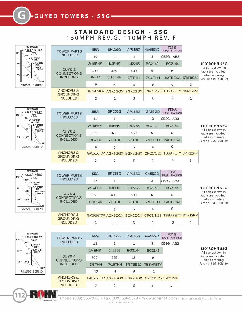
Phone (309) 566-3000 • Fax (309) 566-3079 • www.rohnnet.com • The Industry Standard
G G U Y E D T O W E R S - 5 5 G
S T A N D A R D D E S I G N - 5 5 G
1 3 0 M P H R E V . G , 1 1 0 M P H R E V . F
112© 2011 ROHN PRODUCTS LLC
P/N: 55G130R100
100’ TOWER
95’
18.7 14.6OR
124’
80’
3/16” EHS(399#)
102’
63’
33’ 87’
1/4” EHS(665#)
100’ ROHN 55G
All parts shown in
table are included
when ordering
Part No: 55G130R100
TOWER PARTS
INCLUDED
GUYS &
CONNECTIONS
INCLUDED
ANCHORS &
GROUNDING
INCLUDED
55G BPC55G APL55G GA55GD
BGK2GGX
10 1 1 3
33
FDNS
BASE ANCHOR
3/16EHS
300’
5/16THH
6
1/4EHS
325’
3/8THH
6
142265
400’
7/16THH
6
BG2142
6
1/2TBE&J
6
BG2144
6
AGK1GGX
1
BG2146
6
TBSAFETY
3
5/8TBE&J
3
3
5/16” EHS(1120#)
P/N: 55G130R110
110’ TOWER
105’
18.2 14.2OR
137’
88’
3/16” EHS(399#)
114’
72’
35’ 95’
1/4” EHS(665#)
110’ ROHN 55G
All parts shown in
table are included
when ordering
Part No: 55G130R110
TOWER PARTS
INCLUDED
GUYS &
CONNECTIONS
INCLUDED
ANCHORS &
GROUNDING
INCLUDED
55G BPC55G APL55G GA55GD
BGK2GGX
11 1 1 3
33
FDNS
BASE ANCHOR
3/16EHS
325’
5/16THH
6
1/4EHS
375’
3/8THH
6
142265
450’
7/16THH
6
BG2142
6
BG2144
6
AGK1GGX
1
BG2146
6
TBSAFETY
3
5/8TBE&J
9
GAC5655TOP
3
5/16” EHS(1120#)
P/N: 55G130R120
120’ TOWER
115’
17.7 14.0OR
150’
96’
3/16” EHS(399#)
123’
77’
38’ 103’
1/4” EHS(665#)
120’ ROHN 55G
All parts shown in
table are included
when ordering
Part No: 55G130R120
TOWER PARTS
INCLUDED
GUYS &
CONNECTIONS
INCLUDED
ANCHORS &
GROUNDING
INCLUDED
55G BPC55G APL55G GA55GD
BGK2GGX
12 1 1 3
33
FDNS
BASE ANCHOR
3/16EHS
350’
5/16THH
6
1/4EHS
400’
3/8THH
6
142265
500’
7/16THH
6
BG2142
6
BG2144
6
AGK1GGX
1
BG2146
6
TBSAFETY
3
5/8TBE&J
9
GAC5655TOP
3
5/16” EHS(1120#)
P/N: 55G130R130
130’ TOWER
125’
17.3 13.8OR
163’
104’
133’
83’
42’ 112’
1/4” EHS(665#)
130’ ROHN 55G
All parts shown in
table are included
when ordering
Part No: 55G130R130
TOWER PARTS
INCLUDED
GUYS &
CONNECTIONS
INCLUDED
ANCHORS &
GROUNDING
INCLUDED
55G BPC55G APL55G GA55GD
BGK2GGX
13 1 1 3
33
FDNS
BASE ANCHOR
1/4EHS
800’
3/8THH
12
142265
525’
7/16THH
6
BG2144
12
AGK1GGX
1
BG2146
6
TBSAFETY
3
5/8TBE&J
9
GAC5655TOP
3
5/16” EHS(1120#)
CB2G AB2
CB2G AB3
CB2G AB3
CB2G AB3
18.0
16.0
14.0
12.0
GAC3455TOP
CPC1/1.25
CPC1/1.25
CPC1/1.25
CPC.5/.75
3/4x12PP
1
3/4x12PP
1
3/4x12PP
1
3/4x12PP
1

S T A N D A R D D E S I G N - 5 5 G
1 3 0 M P H R E V . G , 1 1 0 M P H R E V . F
Phone (309) 566-3000 • Fax (309) 566-3079 • www.rohnnet.com • The Industry Standard
GG U Y E D T O W E R S - 5 5 G
113© 2011 ROHN PRODUCTS LLC
140’ ROHN 55G
Al l par ts shown in
table are inc luded
when order ing
Par t No: 55G130R140
TOWER PARTS
INCLUDED
GUYS &
CONNECTIONS
INCLUDED
ANCHORS &
GROUNDING
INCLUDED
55G BPC55G APL55G GA55GD
BGK2GGX
14 1 1 4
33
FDNS
BASE ANCHOR
3/16EHS
375’
5/16THH
6
1/4EHS
900’
3/8THH
12
142265
575’
7/16THH
6
BG2142
6
BG2144
12
AGK1GGX
1
BG2146
6
TBSAFETY
3
5/8TBE&J
3
GAC5655TOP
3
P/N: 55G130R140
140’ TOWER
135’
16.9 13.6OR
175’
112’
151’101’
34’ 117’
67’131’ 3/16” EHS
(399#)
1/4” EHS(665#)
150’ ROHN 55G
Al l par ts shown in
table are inc luded
when order ing
Par t No: 55G130R150
TOWER PARTS
INCLUDED
GUYS &
CONNECTIONS
INCLUDED
ANCHORS &
GROUNDING
INCLUDED
55G BPC55G APL55G GA55GD
BGK2GGX
15 1 1 4
33
FDNS
BASE ANCHOR
3/16EHS
400’
5/16THH
6
1/4EHS
975’
3/8THH
12
142265
600’
7/16THH
6
BG2142
6
BG2144
12
AGK1GGX
1
BG2146
6
TBSAFETY
3
5/8TBE&J
3
GAC5655TOP
3
P/N: 55G130R150
150’ TOWER
145’
16.6 13.4OR
188’
120’
161’
108’
36’ 125’
72’140’ 3/16” EHS
(399#)
1/4” EHS(665#)
160’ ROHN 55G
Al l par ts shown in
table are inc luded
when order ing
Par t No: 55G130R160
TOWER PARTS
INCLUDED
GUYS &
CONNECTIONS
INCLUDED
ANCHORS &
GROUNDING
INCLUDED
55G BPC55G APL55G GA55GD
BGK2GGX
16 1 1 4
33
FDNS
BASE ANCHOR
3/16EHS
450’
5/16THH
6
1/4EHS
1050’
3/8THH
12
142265
650’
7/16THH
6
BG2142
6
BG2144
12
AGK1GGX
1
BG2146
6
TBSAFETY
3
5/8TBE&J
12
GAC5655TOP
3
P/N: 55G130R160
160’ TOWER
155’
16.3 13.2OR
201’
128’
173’
116’
39’ 134’
78’150’ 3/16” EHS
(399#)
1/4” EHS(665#)
170’ ROHN 55G
Al l par ts shown in
table are inc luded
when order ing
Par t No: 55G130R170
TOWER PARTS
INCLUDED
GUYS &
CONNECTIONS
INCLUDED
ANCHORS &
GROUNDING
INCLUDED
55G BPC55G APL55G GA55GD
BGK2GGX
17 1 1 4
33
FDNS
BASE ANCHOR
3/16EHS
475’
5/16THH
6
1/4EHS
1100’
3/8THH
12
142265
700’
7/16THH
6
BG2142
6
3/4TBE&J
12
BG2144
12
AGK1GGX
1
BG2146
6
TBSAFETY
3
GAC5755TOP
3
5/16” EHS(1120#)
5/16” EHS(1120#)
5/16” EHS(1120#)
P/N: 55G130R170
170’ TOWER
165’
16.0 13.0OR
214’
136’
184’
124’
41’ 142’
83’159’ 3/16” EHS
(399#)
1/4” EHS(665#)
5/16” EHS(1120#)
CB3G AB3
CB3G AB3
CB3G AB3
CB3G AB4
11.0
10.0
9.8
9.6
CPC1.5/2
CPC1/1.25
CPC1/1.25
CPC1/1.25 3/4x12PP
1
3/4x12PP
1
3/4x12PP
1
3/4x12PP
1

Phone (309) 566-3000 • Fax (309) 566-3079 • www.rohnnet.com • The Industry Standard
G G U Y E D T O W E R S - 5 5 G
S T A N D A R D D E S I G N - 5 5 G
1 3 0 M P H R E V . G , 1 1 0 M P H R E V . F
114© 2011 ROHN PRODUCTS LLC
180’ ROHN 55G
Al l par ts shown in
table are inc luded
when order ing
Par t No: 55G130R180
TOWER PARTS
INCLUDED
GUYS &
CONNECTIONS
INCLUDED
ANCHORS &
GROUNDING
INCLUDED
55G BPC55G APL55G GA55GD
BGK2GGX
18 1 1 5
33
FDNS
BASE ANCHOR
3/16EHS
1000’
5/16THH
12
1/4EHS
1225’
3/8THH
12
142265
725’
7/16THH
6
BG2142
12
3/4TBE&J
15
BG2144
12
AGK1GGX
1
BG2146
6
TBSAFETY
3
GAC5755TOP
3
P/N: 55G130R180
180’ TOWER
175’15.8 12.9OR
227’
144’
202’
142’
35’
105’
178’
3/16” EHS(399#)161’
148’
72’
5/16” EHS(1120#)
1/4” EHS(665#)
P/N: 55G130R190
190’ TOWER
185’15.5 12.7OR
239’
152’
215’
152’
41’
115’
191’
173’
157’
82’
5/16” EHS(1120#)
1/4” EHS(665#)
190’ ROHN 55G
Al l par ts shown in
table are inc luded
when order ing
Par t No: 55G130R190
TOWER PARTS
INCLUDED
GUYS &
CONNECTIONS
INCLUDED
ANCHORS &
GROUNDING
INCLUDED
55G BPC55G APL55G GA55GD
BGK2GGX
19 1 1 5
33
FDNS
BASE ANCHOR
1/4EHS
2350’
3/8THH
24
142265
775’
7/16THH
6
3/4TBE&J
15
BG2144
24
AGK1GGX
1
BG2146
6
TBSAFETY
3
GAC5755TOP
3
CB3G AB4
CB4G AB4
9.0
9.2
CPC1.5/2
CPC1.5/2
3/4x12PP
1
3/4x12PP
1

GG U Y E D T O W E R S - 5 5 G
* TOWERS MOUNTED ON THESE BASES MUST BE BRACKETED OR GUYED AT ALL TIMES. TEMPORARY STEEL GUYING MAY ALSO BE NECESSARY DURING INSTALLATION AND DISMANTLING.
BEARING PLATE
BPL55GCONVERTS STANDARD SECTION TO A
TOP SECTION. HOLE PATTERN FITSTB3 (2” O.D.) AND TB4 (3” O.D.) THRUST
BEARING.
Phone (309) 566-3000 • Fax (309) 566-3079 • www.rohnnet.com • The Industry Standard
P A R T S & A C C E S S O R I E S
115
© 2011 ROHN PRODUCTS LLC
ACCESSORY SHELF
AS455GFOR MOUNTING MANY POPULARROTORS. FIELD DRILLING MAY BE NECESSARY FOR SOME ROTORS.
FACE MOUNT
DM55G2 - 2 3/8” O.D. 5’ LONGDM554 - 4 1/2” O.D. 5’ LONG
SIDE ARM BRACKET
SA253UAMOUNTING TUBE PROVIDED IS 3’ LONG,
2 - 1/4” O.D.
TOP MOUNT
55TDMKD - NO MAST55TDM2S3KD - 2 3/8” O.D. MAST
55TDM25S3KD - 2 7/8” O.D. MAST55TDM3S3KD - 3 1/2” O.D. MAST
55TDM35S3KD - 4” O.D. MAST55TDM4S3KD - 4 1/2” O.D. MAST
MOUNTING TUBE PROVIDED IS 7’.
TAPERED BASE*
55TG - STANDARD
55TGIA - USE WITH A4197L BASE INSULATOR
55TGIAA - USE WITH A4722B BASE INSULATOR
INSULATOR AND PIER PIN MUST BE ORDEREDSEPARATELY.
TOP PLATE
APL55GFOR MOUNTING BEACON OR
LIGHTNING ROD.
LIGHTNING ROD
LRCL5’ COPPER CLAD, MOUNTS TO APL55G.
PIER PIN
3/4X12PP
FOR USE WITH BPC55G
EMBEDDED IN CONCRETE.
PIER PIN MUST BE ORDEREDSEPARATELY, UNLESS BEING
PURCHASED AS PART OFA COMPLETE TOWER KIT.
5’ SHORT BASE
SB55G
FOR EMBEDMENT IN CONCRETE.
FLAT ROOF MOUNT
FR55G*BOLTS DIRECTLY TO FLAT ROOF SURFACE.
CONCRETE BASE PLATE
BPC55G*FOR USE WITH 3/4X12PP PIER PIN
EMBEDDED IN CONCRETE.
CONCRETE BASE PLATE IS TO BEUSED FOR BRACKETED ANDGUYED APPLICATIONS ONLY.
Adjustable
2.5’ - 3.0’

CLIMBING HARNESS
TTFBH-4DJOURNEYMAN HARNESS
TTFBH-C/PPROFESSIONAL HARNESS
SAFETY CABLE SYSTEM
ORDERING INFORMATION
TOWER HEIGHT
50’
100’
150’
200’
250’
300’
350’
400’
PARTNUMBER
TT0504555
TT1004555
TT1504555
TT2004555
TT2504555
TT3004555
TT3504555
TT4004555
SAFETY CABLESLIDER WITH CARABINEER
TT-WG-500-W/SMC
G G U Y E D T O W E R S - 5 5 G
Phone (309) 566-3000 • Fax (309) 566-3079 • www.rohnnet.com • The Industry Standard
P A R T S & A C C E S S O R I E S
116© 2011 ROHN PRODUCTS LLC
SAFETY RING
SR55SNAPS INTO PLACE AT ANY LEVEL.
NO BOLTS REQUIRED.
WORK PLATFORM
WP55GSNAPS INTO PLACE AT ANY LEVEL.
NO BOLTS REQUIRED.
SAFETY CABLE SLIDER AND CLIMBINGHARNESS MUST BE ORDERED SEPARATELY.
HEAVY DUTY UNIVERSAL
HOUSE BRACKET
HBUTVROADJUSTABLE TO POSITION TOWER
18” - 36” FROM WALL.
THRUST BEARING
TB3 - SUPPORTS UP TO 2” O.D. MAST.
TB4 - SUPPORTS UP TO 3” O.D. MAST.
MOUNTS TO BPL55G.
GUY BRACKET
GA55GDMOUNTS TO TOWER AT ANY
HORIZONTAL BRACE.
TORQUE ARM STABILIZER
ASSEMBLY
TA55ANTI-TWIST DEVICE LOCATED IN THE
AREA OF ANTENNAS. PROVIDES SIX-WAYGUYING. BOLTS TO TOWER AT ANY
SECTION JOINT. ATTACHED WITHJOINT BOLTS. MUST BE INSTALLED AS
SECTIONS ARE JOINED TOGETHER.
TORQUE BAR
TB55DOPTIONAL, FOR USE WITH GA55GD.
REQUIRES (1) 3/8” SHACKLE FOR EACH BAR.
ANTI-CLIMB PANELS
455ACL3THREE ANTI-CLIMB PANELS BOLT TO STANDARD TOWER SECTION.

GG U Y E D T O W E R S - 5 5 G
Phone (309) 566-3000 • Fax (309) 566-3079 • www.rohnnet.com • The Industry Standard117
© 2011 ROHN PRODUCTS LLC
REV G
ANCHOR GROUNDING
AGK1GGX
REV G
BASE GROUNDING
BGK2GGX
A N C H O R I N F O R M A T I O N
3/8”
2”
12”
3/4”P/N STAMPED HERE
GAC3455TOP
1/2”
2 1/2”
12”
120”
1 1/4”P/N STAMPED HERE
GAC5655TOP
81”
3/4”
3”
12”
168”
1 7/16”P/N STAMPED HERE
GAC5755TOP
11/16”
13/16”
15/16”
4” x 4” x 3/8” angle
5” x 5” x 3/8” angle
CL of hole to edgeof plate = 1 1/4”
CL of hole to edgeof plate = 1”
CL of hole to edgeof plate = 1 1/4”
5” x 5” x 3/8” angle
Ground Wire
Ground Rod Clamp
Ground Rod
Clamp
6” Min.
Attach to leg withsupplied leg clamp
Ground Wire
6” Min.Ground Rod Clamp
Ground Rod,3 provided (to be installed
at 120 separation at 20’ spacing.o

All around stirrupsequally spaced 12” O.C. anchored with 90hooks around a horizontal bar
Top and bottom horizontal bars equally spaced
C
B
A
Ground Line
D
Anchor rod
o
Additional bar atcenter-line eachside, when required
S T A N D A R D A N C H O R B L O C K S
Block
AB2
AB3
AB4
AB5
AB6
A
4’ - 0”
6’ - 0”
6‘ - 0”
8’ - 0”
8’ - 0”
Concrete Vol.(Cu. Yds.)
1.33 Per Block4.0 Total for 3
1.0 Per Block3.0 Total for 3
2.0 Per Block6.0 Total for 3
2.22 Per Block6.7 Total for 3
2.96 Per Block8.9 Total for 3
B
1‘ - 6”
1’ - 6”
1’ - 6”
2’ - 0”
2’ - 0”
C
4‘ - 0“
3’ - 0”
4‘ - 0“
3’ - 0”
4’ - 0”
Horizontal Bars(Qty. & Size)
(5) #6 Bars, Top Layer(5) #6 Bars, Bottom Layer
(0) Additional Bar, Each Side
(4) #6 Bars, Top Layer(4) #6 Bars, Bottom Layer
(0) Additional Bar, Each Side
(5) #6 Bars, Top Layer(5) #6 Bars, Bottom Layer
(0) Additional Bar, Each Side
(4) #7 Bars, Top Layer(4) #7 Bars, Bottom Layer
(1) Additional Bar, Each Side
(5) #7 Bars, Top Layer(5) #7 Bars, Bottom Layer
(1) Additional Bar, Each Side
D
6’ - 0”
6’ - 0”
9’ - 0”
10’ - 0”
10’ - 0”
Anchor Dimensions (in.) Stirrup Size& Spacing
#3 @ 12” O.C.
#3 @ 12” O.C.
#4 @ 12” O.C.
#4 @ 12” O.C.
#4 @ 12” O.C.
Phone (309) 566-3000 • Fax (309) 566-3079 • www.rohnnet.com • The Industry Standard
G G U Y E D T O W E R S - 5 5 G
118© 2011 ROHN PRODUCTS LLC
Refer to page 119 for anchor rod installation angles.

GG U Y E D T O W E R S - 5 5 G
Phone (309) 566-3000 • Fax (309) 566-3079 • www.rohnnet.com • The Industry Standard119
© 2011 ROHN PRODUCTS LLC
A N C H O R R O D I N S T A L L A T I O N A N G L E S
120o
Ground Line
Rod Angle(in degrees)
Tower
Height
100’
110’
120’
130’
140’
150’
160’
170’
180’
190’
200’
220’
240’
260’
280’
300’
320’
340’
360’
380’
400’
Inner Rod
Number
GAC3455TOP
GAC3455TOP
GAC3455TOP
GAC3455TOP
GAC3455TOP
GAC3455TOP
GAC3455TOP
GAC3455TOP
GAC3455TOP
GAC5655TOP
GAC5655TOP
GAC5755TOP
GAC5755TOP
GAC3455TOP
GAC3455TOP
GAC3455TOP
GAC3455TOP
GAC3455TOP
GAC3455TOP
GAC3455TOP
GAC3455TOP
InnerRod
Angle
42
42
40
40
40
39
39
38
38
40
40
38
37
43
42
39
40
40
40
40
38
55G | 90MPH
Outer Rod
Number
-
-
-
-
-
-
-
-
-
-
-
-
-
GAC5655TOP
GAC5655TOP
GAC5655TOP
GAC5655TOP
GAC5655TOP
GAC5655TOP
GAC5655TOP
GAC5655TOP
OuterRod
Angle
-
-
-
-
-
-
-
-
-
-
-
-
-
42
42
43
43
42
42
42
42
Tower
Height
100’
110’
120’
130’
140’
150’
160’
170’
180’
190’
200’
220’
240’
260’
280’
300’
Inner Rod
Number
GAC3455TOP
GAC3455TOP
GAC3455TOP
GAC3455TOP
GAC3455TOP
GAC5655TOP
GAC5655TOP
GAC5655TOP
GAC5655TOP
GAC5655TOP
GAC5655TOP
GAC3455TOP
GAC3455TOP
GAC3455TOP
GAC3455TOP
GAC3455TOP
InnerRod
Angle
41
40
40
40
38
38
39
38
38
38
38
42
40
41
40
39
55G | 110MPH
Outer Rod
Number
-
-
-
-
-
-
-
-
-
-
-
GAC5655TOP
GAC5655TOP
GAC5655TOP
GAC5655TOP
GAC5655TOP
OuterRod
Angle
-
-
-
-
-
-
-
-
-
-
-
43
44
44
43
43
Tower
Height
100’
110’
120’
130’
140’
150’
160’
170’
180’
190’
Rod
Number
GAC3455TOP
GAC5655TOP
GAC5655TOP
GAC5655TOP
GAC5655TOP
GAC5655TOP
GAC5655TOP
GAC5755TOP
GAC5755TOP
GAC5755TOP
Rod
Angle
41
40
40
40
40
40
40
38
38
37
55G | 130MPH
Tower Plan Anchor Rod Angle

S T A N D A R D B A S E P I E R S
Phone (309) 566-3000 • Fax (309) 566-3079 • www.rohnnet.com • The Industry Standard
G G U Y E D T O W E R S - 5 5 G
120© 2011 ROHN PRODUCTS LLC
Base
CB1G*
CB2G
CB3G
CB4G
CB5G
A
2’ - 6”
3’ - 0”
3’ - 6”
4’ - 0”
2’ - 0”
Vertical Bars(No. & Size)
(8) #7
(10) #7
(12) #7
(12) #8
(8) #6
Concrete Vol.(Cu. Yds.)
Round Pier
1.0
1.2
1.6
2.1
1.1
B
2’ - 6”
3’ - 0”
3’ - 6”
4’ - 0”
4’ - 0”
C
N/A
N/A
N/A
N/A
1’ - 0”
Horiz. Barsin Pad
(No. & Size)
NONE
NONE
NONE
NONE
(5) #5(Total of 10)
D
4’ - 0”
4’ - 0”
4’ - 0”
4’ - 0”
4’ - 0”
E
N/A
N/A
N/A
N/A
3’ - 3”
F
N/A
N/A
N/A
N/A
1’ - 3”
AlternateSquarePier
PLAN VIEW
A
B
No. 4 Circular ties, 3” O.C. with 24” laps
Vertical bars equally spaced
(2) No. 4 Circular ties, 2-1/2” O.C. with 2“ cover with 24” laps
4” Projection
6”
No. 4 Circular ties, 3” Max. O.C. with 24” laps
Vertical re-bars equally spacedwith 90 hooks at bottom (for CB5G)
Roughen construction joint toa full amplitude of 1/4”
Foundation Pad
Horizontal reinforcing steel bars equally spacedeach way
C
E
D
F
ELEVATION VIEW
B
Pier Pin
Grade
* Square pier option must be used for CB1G.
A CL
LC

Phone (309) 566-3000 • Fax (309) 566-3079 • www.rohnnet.com • The Industry Standard121
© 2011 ROHN PRODUCTS LLC
N O T E S

Phone (309) 566-3000 • Fax (309) 566-3079 • www.rohnnet.com • The Industry Standard
G G U Y E D T O W E R S - 6 5 G
S T A N D A R D 6 5 G G U Y E D T O W E R
122© 2011 ROHN PRODUCTS LLC
The first. The original.ROHN 65G
Per Rev G requirements, any structure greater than 10’ requires a climber
safety device. Please see page 142 for ordering information.
REV. G
includes
REV. F &
GENERAL USE
The 65G is designed to provide excellent rigidity
and strength in applications up to 500’. This
high strength design covers a wide variety of
communication uses. The 65G is completely
pre-fabricated in welded sections, allowing for
quick and convenient installation.
FEATURES
• Completely hot-dip galvanized after fabrication
• Built on a 24 1/4” equilateral triangle design
• High strength tubular legs joined by Zig-Zag®
cross members
• Each section contains all required nuts and bolts
shipped with section
• Continuous solid round steel bracing
65G
Mixing copies of ROHN towers with ROHN towers is dangerous and voids all engineering and warranty data supplied by ROHN. Materials used by others are not the same quality and have not been tested or engineered by ROHN. MixingROHN tower sections with non-ROHN products may cause tower failure or injury.
CAUTION

1.90” O.D.(0.145” Wall)
STANDARD SECTION
65G - 10’ Section6520G - 20’ Section
Phone (309) 566-3000 • Fax (309) 566-3079 • www.rohnnet.com • The Industry Standard
GG U Y E D T O W E R S - 6 5 G
S T A N D A R D 6 5 G G U Y E D T O W E R
S E C T I O N S
123
“
5/8” O.D. Solid Bracing
TAPERED BASE
65TGH - 10’ Section
5/8” O.D. Solid Bracing
© 2011 ROHN PRODUCTS LLC
PARTS & ACCESSORIES PAGES 141-142GROUNDING INFORMATION PAGE 143FOUNDATION INFORMATION PAGES 143-146
QUICK REFERENCE
21”14”
24 1/4”
Optional double braced sections are available upon request.
Optional WaveguideBrackets (KY2041A)
1.90” O.D.(0.145” Wall)

EPA (SQ. FT.) For Exposure B, Revision G
EPA (SQ. FT.) For Exposure C, Revision G
EPA (SQ. FT.), Revision F
P/N 65G90R100
122’
92’
92’
45’
80’
3/16” EHS(399#)
60.8
68.0
78.1
P/N 65G90R100
Tower ModelWindspeed (Rev. G) ROHN Tower
Tower Height (ft.)
EPA= Effective Projected Area
Phone (309) 566-3000 • Fax (309) 566-3079 • www.rohnnet.com • The Industry Standard
G G U Y E D T O W E R S - 6 5 G
B U Y E R S G U I D ES T A N D A R D D E S I G N S - 6 5 G
9 0 M P H R E V . G [ 3 S E C O N D G U S T ]7 0 M P H R E V . F [ F A S T E S T M I L E ]
124© 2011 ROHN PRODUCTS LLC
5/16” EHS(1,120#)
Guy Initial Tension
This document is to serve as a guide for sizing and purchasing the 65G tower. Tower and foundation installations shouldbe performed by qualified and experienced personnel using assembly drawings provided with each tower.
DESIGN NOTES:
1. Tower designs are in accordance with ANSI/TIA-222-F and ANSI/TIA-222-G, Class I Structures, Topographic Category 1. 2. Design assumes towers are installed on level ground. Lower EPA values will apply for roof mounted towers or for sites located on unusual terrain. 3. Designs assume two 7/8” diameter lines on each tower face. 4. Anchor radius is from tower base to intersection of anchor rod with ground. 5. Guy chord lengths shown are based on level ground. Initial tensions for guys are shown in ( ) in pounds at 60º Fahrenheit. 6. Antenna and mounts are assumed symmetrically placed at the tower top.
PARTS LIST NOTES:
1. Items listed are required for complete guyed towers. 2. Base and anchor foundations listed refer to standard foundation designations. 3. Guys provided with each standard tower are based on level ground conditions with an additional 6% length. 4. Rev G anchor grounding (AGK1GGX) and base grounding (BGK2GGX) are included with the tower material. 5. Assembly drawings and a safety package (P/N: ACWS) are included with each tower. 6. Parts lists are subject to change based on availability or revised design criteria.
FOR FOUNDATION INFORMATION, PLEASE SEE PAGES 143-146.
FOR GENERAL INSTALLATION INFORMATION, PLEASE SEE PAGES 147-153.
Design Criteria

P/N: 65G90R130
130’ TOWER
120’
72.3 57.3OR
159’
104’
5/16” EHS(1,120#)
120’60’
3/16” EHS(399#)
63.4
P/N: 65G90R120
120’ TOWER
112’
73.9 58.5OR
148’
96’
5/16” EHS(1,120#)
111’55’
3/16” EHS(399#)
64.8
S T A N D A R D D E S I G N - 6 5 G
9 0 M P H R E V . G , 7 0 M P H R E V . F
Phone (309) 566-3000 • Fax (309) 566-3079 • www.rohnnet.com • The Industry Standard
GG U Y E D T O W E R S - 6 5 G
125© 2011 ROHN PRODUCTS LLC
P/N: 65G90R100
100’ TOWER
92’
78.0 60.8OR
122’
80’
5/16” EHS(1,120#)
92’45’
3/16” EHS(399#)
P/N: 65G90R110
110’ TOWER
100’
75.8 59.6OR
133’
88’
5/16” EHS(1,120#)
102’52’
3/16” EHS(399#)
P/N: 65G90R140
140’ TOWER
129’
70.7 56.6OR
171’
112’
3/16” EHS(399#)
141’
86’
43’ 120’
5/16” EHS(1,120#)
TOWER PARTS
INCLUDED
GUYS &
CONNECTIONS
INCLUDED
ANCHORS &
GROUNDING
INCLUDED
65G 65TGH 6520G GA65GD
142265 3/16EHS BG2142 BG2146 5/16THH
GAC3455TOP AGK1GGX BGK2GGX
1 1 4 2
400’ 300’ 6 6 6
3 1 3
100’ ROHN 65G
All parts shown in
table are included
when ordering
Part No: 65G90R100
FDNS
BASE ANCHOR
7/16THH
6 3
1/2TBE&J
3
5/8TBE&J
TOWER PARTS
INCLUDED
GUYS &
CONNECTIONS
INCLUDED
ANCHORS &
GROUNDING
INCLUDED
65TGH 6520G APL4HA GA65GD
142265 3/16EHSBG2142 BG2146 5/16THH
AGK1GGX BGK2GGX
1 5 1 2
425’ 325’ 6 6 6
3 1 3
110’ ROHN 65G
All parts shown in
table are included
when ordering
Part No: 65G90R110
FDNS
BASE ANCHOR
7/16THH
6 3
1/2TBE&J
3
5/8TBE&J
TOWER PARTS
INCLUDED
GUYS &
CONNECTIONS
INCLUDED
ANCHORS &
GROUNDING
INCLUDED
65G 65TGH 6520G GA65GD
142265 3/16EHS BG2142 BG2146 5/16THH
AGK1GGX BGK2GGX
1 1 5 2
475’ 375’ 6 6 6
3 1 3
120’ ROHN 65G
All parts shown in
table are included
when ordering
Part No: 65G90R120
FDNS
BASE ANCHOR
7/16THH
6 3
1/2TBE&J
3
5/8TBE&J
TOWER PARTS
INCLUDED
GUYS &
CONNECTIONS
INCLUDED
ANCHORS &
GROUNDING
INCLUDED
65TGH 6520G GA65GD APL4HA
142265 3/16EHS BG2142 BG2146 5/16THH
AGK1GGX BGK2GGX
1 6 2 1
525’ 400’ 6 6 6
3 1 3
130’ ROHN 65G
All parts shown in
table are included
when ordering
Part No: 65G90R130
FDNS
BASE ANCHOR
7/16THH
6 3
1/2TBE&J
3
5/8TBE&J
TOWER PARTS
INCLUDED
GUYS &
CONNECTIONS
INCLUDED
ANCHORS &
GROUNDING
INCLUDED
65G 65TGH 6520G APL4HA
142265 3/16EHS BG2142 BG2146 5/16THH
AGK1GGX BGK2GGX
1 1 6 1
550’ 850’ 12 6 12
3 1 3
140’ ROHN 65G
All parts shown in
table are included
when ordering
Part No: 65G90R140
FDNS
BASE ANCHOR
7/16THH
6 3
1/2TBE&J
6
5/8TBE&J
CPC.5/.75
3
TBSAFETY
3
CPC.5/.75
3
TBSAFETY
3
TBSAFETY
3
CPC.5/.75
3
TBSAFETY
3
CPC.5/.75
3
TBSAFETY
3
CPC.5/.75
3
CB2G AB2
CB2G AB2
CB2G AB2
CB2G AB2
CB2G AB2
68.0
66.2
62.2
APL4HA
1
GAC3455TOP
APL4HA
1
GAC3455TOP
GAC3455TOP
GA65GD
3
GAC3455TOP
15/16x16PP
1
15/16x16PP
1
15/16x16PP
1
15/16x16PP
1
15/16x16PP
1

P/N: 65G90R180
180’ TOWER
168’
65.6 53.7OR
221’
144’
3/16” EHS(399#)
182’
112’
56’ 155’
5/16” EHS(1,120#)
1/4” EHS(665#)
P/N: 65G90R170
170’ TOWER
159’
66.7 54.3OR
209’
136’
3/16” EHS(399#)
172’
106’
53’ 146’
5/16” EHS(1,120#)
59.0
Phone (309) 566-3000 • Fax (309) 566-3079 • www.rohnnet.com • The Industry Standard
G G U Y E D T O W E R S - 6 5 G
S T A N D A R D D E S I G N - 6 5 G
9 0 M P H R E V . G , 7 0 M P H R E V . F
126© 2011 ROHN PRODUCTS LLC
P/N: 65G90R150
150’ TOWER
138’
69.4 55.8OR
183’
120’
3/16” EHS(399#)
151’
92’
46’ 129’
5/16” EHS(1,120#)
P/N: 65G90R160
160’ TOWER
152’
67.8 55.0OR
199’
128’
3/16” EHS(399#)
162’
100’
52’ 138’
5/16” EHS(1,120#)
TOWER PARTS
INCLUDED
GUYS &
CONNECTIONS
INCLUDED
ANCHORS &
GROUNDING
INCLUDED
65TGH 6520G APL4HA GA65GD
142265 3/16EHS BG2142 BG2146 5/16THH
GAC3455TOP AGK1GGX BGK2GGX
1 7 1 3
600’ 900’ 12 6 12
3 1 3
150’ ROHN 65G
All parts shown in
table are included
when ordering
Part No: 65G90R150
FDNS
BASE ANCHOR
7/16THH
6 3
1/2TBE&J
6
5/8TBE&J
TOWER PARTS
INCLUDED
GUYS &
CONNECTIONS
INCLUDED
ANCHORS &
GROUNDING
INCLUDED
65G 65TGH 6520G APL4HA
142265 3/16EHS BG2142 BG2146 5/16THH
AGK1GGX BGK2GGX
1 1 7 1
650’ 975’ 12 6 12
3 1 3
160’ ROHN 65G
All parts shown in
table are included
when ordering
Part No: 65G90R160
FDNS
BASE ANCHOR
7/16THH
6 9
5/8TBE&J
TOWER PARTS
INCLUDED
GUYS &
CONNECTIONS
INCLUDED
ANCHORS &
GROUNDING
INCLUDED
65TGH 6520G APL4HA GA65GD
142265 3/16EHS BG2142 BG2146 5/16THH
GAC5655TOP AGK1GGX BGK2GGX
1 8 1 3
675’ 1025’ 12 6 12
3 1 3
170’ ROHN 65G
All parts shown in
table are included
when ordering
Part No: 65G90R170
FDNS
BASE ANCHOR
7/16THH
6 9
5/8TBE&J
TOWER PARTS
INCLUDED
GUYS &
CONNECTIONS
INCLUDED
65G 65TGH 6520G APL4HA
BG2146 5/8TBE&J 7/16THH
1 1 8 1
6 9 6
180’ ROHN 65G
All parts shown in
table are included
when ordering
Part No: 65G90R180
FDNS
BASE ANCHOR
3/8THH
6
5/16THH
6
CPC.5/.75
3
TBSAFETY
3
CPC1/1.25
3
TBSAFETY
3
CPC1/1.25
3
TBSAFETY
3
CB2G AB2
CB2G AB3
CB3G AB3
CB3G AB3
61.0
60.0
58.2
GA65GD
3
GAC5655TOP
ANCHORS &
GROUNDING
INCLUDED
GAC5655TOP AGK1GGX BGK2GGX
3 1 3
CPC1/1.25
3
TBSAFETY
3
142265 1/4EHS 3/16EHS
725’ 600’ 500’
BG2142
6
BG2144
6
GA65GD
3
15/16x16PP
1
15/16x16PP
1
15/16x16PP
1
15/16x16PP
1

TOWER PARTS
INCLUDED
GUYS &
CONNECTIONS
INCLUDED
ANCHORS &
GROUNDING
INCLUDED
65TGH 6520G APL4HA GA65GD
GAC5655TOP BGK2GGX CPC1/1.25
1 9 1 3
63 3
142265
750’
BG2146
6
1/4EHS
625’
5/8TBE&J
9
3/16EHS
525’
7/16THH
6
BG2142
6
3/8THH
6
BG2144
6
5/16THH
6
AGK1GGX
1
TBSAFETY
3
BASE INNERANCHOR
CB3G AB3
P/N: 65G90R240
240’ TOWER
232’
60.6 50.5OR
301’
192’
258’
173’
58’ 201’
116’224’ 3/16” EHS
(399#)
1/4” EHS(665#)
5/16” EHS(1,120#)
P/N: 65G90R220
220’ TOWER
208’
62.1 51.4OR
272’
176’
235’
156’
52’ 184’
104’204’ 3/16” EHS
(399#)
1/4” EHS(665#)
5/16” EHS(1,120#)
P/N: 65G90R200
200’ TOWER
186’
63.8 52.5OR
245’
160’
3/16” EHS(399#)
202’
124’
62’ 172’
5/16” EHS(1,120#)
1/4” EHS(665#)
Phone (309) 566-3000 • Fax (309) 566-3079 • www.rohnnet.com • The Industry Standard
GG U Y E D T O W E R S - 6 5 G
S T A N D A R D D E S I G N - 6 5 G
9 0 M P H R E V . G , 7 0 M P H R E V . F
127© 2011 ROHN PRODUCTS LLC
200’ ROHN 65G
Al l par ts shown intable are inc luded
when order ingPar t No: 65G90R200
220’ ROHN 65G
Al l par ts shown intable are inc luded
when order ingPar t No: 65G90R220
240’ ROHN 65G
Al l par ts shown intable are inc luded
when order ingPar t No: 65G90R240
54.4
53.0
51.6
P/N: 65G90R190
190’ TOWER
180’
64.8 53.1OR
236’
152’
3/16” EHS(399#)
194’
120’
60’ 163’
5/16” EHS(1,120#)
1/4” EHS(665#)
190’ ROHN 65G
Al l par ts shown intable are inc luded
when order ingPar t No: 65G90R190
57.2
TOWER PARTS
INCLUDED
GUYS &
CONNECTIONS
INCLUDED
65G 65TGH 6520G APL4HA
BG2146 5/8TBE&J 7/16THH
1 1 9 1
6 9 6
FDNS
BASE ANCHOR
3/8THH
6
5/16THH
6
CB3G AB3
ANCHORS &
GROUNDING
INCLUDED
GAC5655TOP AGK1GGX BGK2GGX
3 1 3
CPC1/1.25
3
TBSAFETY
3
142265 1/4EHS 3/16EHS
800’ 650’ 550’
BG2142
6
BG2144
6
GA65GD
3
TOWER PARTS
INCLUDED
GUYS &
CONNECTIONS
INCLUDED
65G 65TGH 6520G APL4HA
BG2146 5/8TBE&J 7/16THH
1 1 10 1
6 12 6
FDNS
BASE ANCHOR
3/8THH
6
5/16THH
12
CB3G AB3
ANCHORS &
GROUNDING
INCLUDED
GAC5655TOP AGK1GGX BGK2GGX
3 1 3
CPC1/1.25
3
TBSAFETY
3
142265 1/4EHS 3/16EHS
875’ 750’ 1250’
BG2142
12
BG2144
6
GA65GD
4
TOWER PARTS
INCLUDED
GUYS &
CONNECTIONS
INCLUDED
65G 65TGH 6520G APL4HA
BG2146 5/8TBE&J 7/16THH
1 1 11 1
6 12 6
FDNS
BASE ANCHOR
3/8THH
6
5/16THH
12
CB3G AB3
ANCHORS &
GROUNDING
INCLUDED
GAC5655TOP AGK1GGX BGK2GGX
3 1 3
CPC1/1.25
3
TBSAFETY
3
142265 1/4EHS 3/16EHS
975’ 825’ 1375’
BG2142
12
BG2144
6
GA65GD
4
15/16x16PP
1
15/16x16PP
1
15/16x16PP
1
15/16x16PP
1
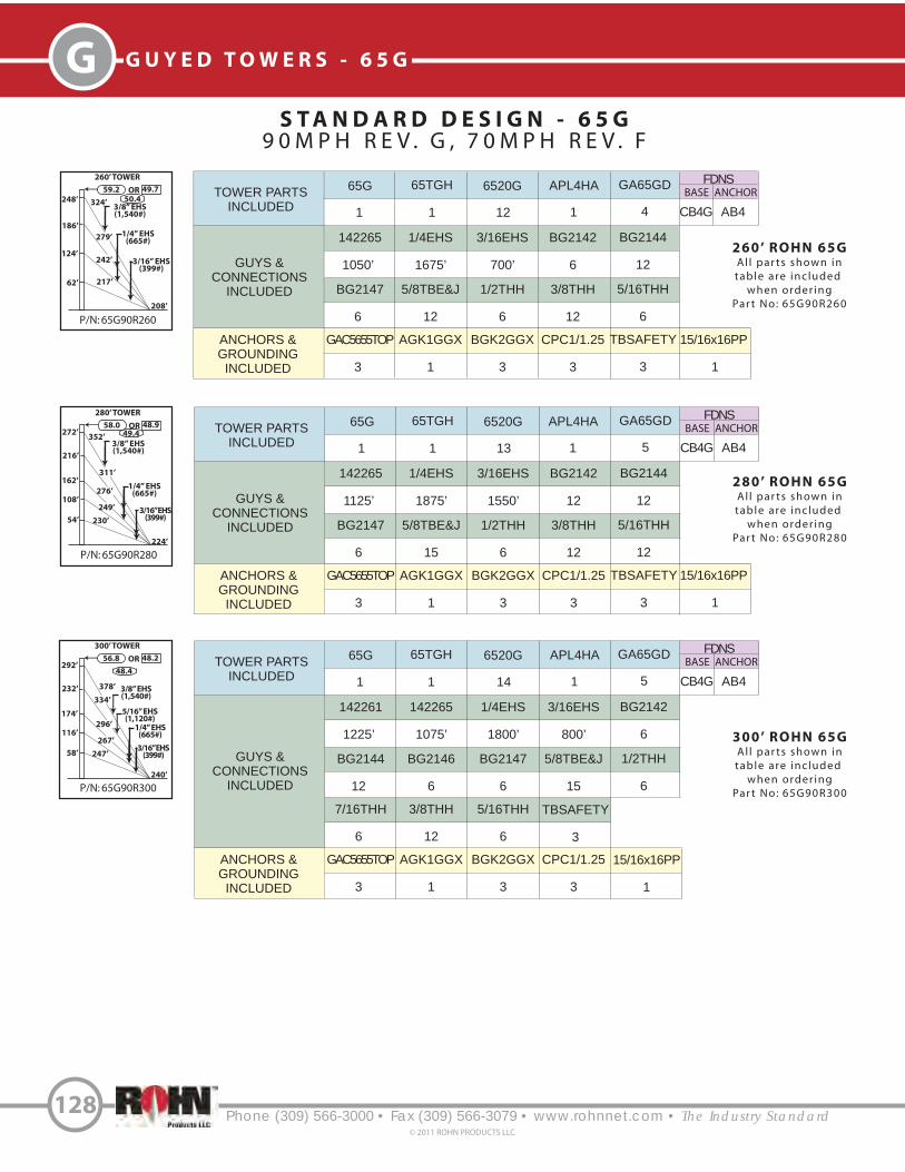
P/N: 65G90R300
300’ TOWER
292’56.8 48.2OR
378’
240’
334’
232’
58’
174’
296’
3/16” EHS(399#)
267’
247’
116’
3/8” EHS(1,540#)
P/N: 65G90R280
280’ TOWER
272’58.0 48.9OR
352’
224’
311’
216’
54’
162’
276’1/4” EHS
(665#)
249’
230’
108’
3/16” EHS(399#)
3/8” EHS(1,540#)
Phone (309) 566-3000 • Fax (309) 566-3079 • www.rohnnet.com • The Industry Standard
G G U Y E D T O W E R S - 6 5 G
S T A N D A R D D E S I G N - 6 5 G
9 0 M P H R E V . G , 7 0 M P H R E V . F
128© 2011 ROHN PRODUCTS LLC
280’ ROHN 65G
Al l par ts shown in
table are inc luded
when order ing
Par t No: 65G90R280
300’ ROHN 65G
Al l par ts shown in
table are inc luded
when order ing
Par t No: 65G90R300
49.4
48.4
1/4” EHS(665#)
P/N: 65G90R260
260’ TOWER
248’
59.2 49.7OR
324’
208’
279’
186’
62’ 217’
124’242’ 3/16” EHS
(399#)
1/4” EHS(665#)
3/8” EHS(1,540#)
260’ ROHN 65G
Al l par ts shown in
table are inc luded
when order ing
Par t No: 65G90R260
50.4TOWER PARTS
INCLUDED
GUYS &
CONNECTIONS
INCLUDED
65G 65TGH 6520G APL4HA
BG2147 5/8TBE&J 1/2THH
1 1 12 1
6 12 6
FDNS
BASE ANCHOR
3/8THH
12
5/16THH
6
CB4G AB4
ANCHORS &
GROUNDING
INCLUDED
GAC5655TOP AGK1GGX BGK2GGX
3 1 3
CPC1/1.25
3
TBSAFETY
3
142265 1/4EHS 3/16EHS
1050’ 1675’ 700’
BG2142
6
BG2144
12
GA65GD
4
TOWER PARTS
INCLUDED
GUYS &
CONNECTIONS
INCLUDED
65G 65TGH 6520G APL4HA
BG2147 5/8TBE&J 1/2THH
1 1 13 1
6 15 6
FDNS
BASE ANCHOR
3/8THH
12
5/16THH
12
CB4G AB4
ANCHORS &
GROUNDING
INCLUDED
GAC5655TOP AGK1GGX BGK2GGX
3 1 3
CPC1/1.25
3
TBSAFETY
3
142265 1/4EHS 3/16EHS
1125’ 1875’ 1550’
BG2142
12
BG2144
12
GA65GD
5
TOWER PARTS
INCLUDED
GUYS &
CONNECTIONS
INCLUDED
65G 65TGH 6520G APL4HA
BG2144 BG2146 BG2147
1 1 14 1
12 6 6
FDNS
BASE ANCHOR
5/8TBE&J
15
1/2THH
6
CB4G AB4
7/16THH 3/8THH 5/16THH
6 12 6
142261 142265 1/4EHS
1225’ 1075’ 1800’
3/16EHS
800’
BG2142
6
GA65GD
5
ANCHORS &
GROUNDING
INCLUDED
GAC5655TOP AGK1GGX BGK2GGX
3 1 3
CPC1/1.25
3
TBSAFETY
3
5/16” EHS(1,120#)
15/16x16PP
1
15/16x16PP
1
15/16x16PP
1

P/N: 65G90R360
360’ TOWER
352’53.9 46.4OR
455’
288’
5/16” EHS(1,120#)
292’
59’
234’
176’
111’
151’
94’
118’338’
371’
410’
1/4” EHS(665#)
Phone (309) 566-3000 • Fax (309) 566-3079 • www.rohnnet.com • The Industry Standard
GG U Y E D T O W E R S - 6 5 G
S T A N D A R D D E S I G N - 6 5 G
9 0 M P H R E V . G , 7 0 M P H R E V . F
129© 2011 ROHN PRODUCTS LLC
360’ ROHN 65G
Al l par ts shown intable are inc luded
when order ingPar t No: 65G90R360
45.8
3/8” EHS(1,540#)
P/N: 65G90R340
340’ TOWER
332’54.8 46.9OR
429’
272’
3/8” EHS(1,540#)
275’
55’
220’
165’
104’
142’
1/4” EHS(665#)
88’
112’318’
350’
387’
P/N: 65G90R320
320’ TOWER
312’55.8 47.5OR
404’
256’
356’248’
62’
186’ 316’
3/16” EHS(399#)
284’
263’
124’
3/8” EHS(1,540#)
320’ ROHN 65G
Al l par ts shown intable are inc luded
when order ingPar t No: 65G90R320
340’ ROHN 65G
Al l par ts shown intable are inc luded
when order ingPar t No: 65G90R340
47.6
46.6
1/4” EHS(665#)
5/16” EHS(1,120#)
3/16” EHS(399#)
TOWER PARTS
INCLUDED
GUYS &
CONNECTIONS
INCLUDED
65G 65TGH 6520G APL4HA
BG2144 BG2146 BG2147
1 1 15 1
12 6 6
FDNS
BASE ANCHOR
5/8TBE&J
15
1/2THH
6
CB5G AB4
7/16THH 3/8THH 5/16THH
6 12 6
142261 142265 1/4EHS
1300’ 1150’ 1925’
3/16EHS
850’
BG2142
6
GA65GD
5
ANCHORS &
GROUNDING
INCLUDED
GAC5655TOP AGK1GGX BGK2GGX
3 1 3
CPC1/1.25
3
TBSAFETY
3
TOWER PARTS
INCLUDED
GUYS &
CONNECTIONS
INCLUDED
65G 65TGH 6520G APL4HA
BG2144 BG2146 BG2147
1 1 16 1
18 6 6
BASE
5/8TBE&J
12
1/2TBE&J
6
CB5G AB2
1/2THH 7/16THH 3/8THH
6 6 18
142261 142265 1/4EHS
1375’ 1250’ 2600’
3/16EHS
350’
BG2142
6
GA65GD
6
ANCHORS &
GROUNDING
INCLUDED
GAC5655TOP AGK1GGX BGK2GGX
3 2 3
CPC.5/.75
3
3
INNERANCHOR
OUTERANCHOR
AB4
5/16THH
6
TBSAFETY
6
GAC3455TOP
CPC1/1.25
3
TOWER PARTS
INCLUDED
GUYS &
CONNECTIONS
INCLUDED
65G 65TGH 6520G APL4HA
BG2144 BG2146 BG2147
1 1 17 1
24 6 6
BASE
1/2THH
6
7/16THH
6
CB6G AB2
142261 142265 1/4EHS
1450’ 1325’ 3100’
5/8TBE&J
12
1/2TBE&J
6
GA65GD
6
ANCHORS &
GROUNDING
INCLUDED
GAC5655TOP AGK1GGX BGK2GGX
3 2 3
CPC.5/.75
33
INNERANCHOR
OUTERANCHOR
AB4
APL1258UM
2
GAC3455TOP
CPC1/1.25
3
3/8THH
24
TBSAFETY
6
5/16” EHS(1,120#)
15/16x16PP
1
15/16x16PP
1
15/16x16PP
1
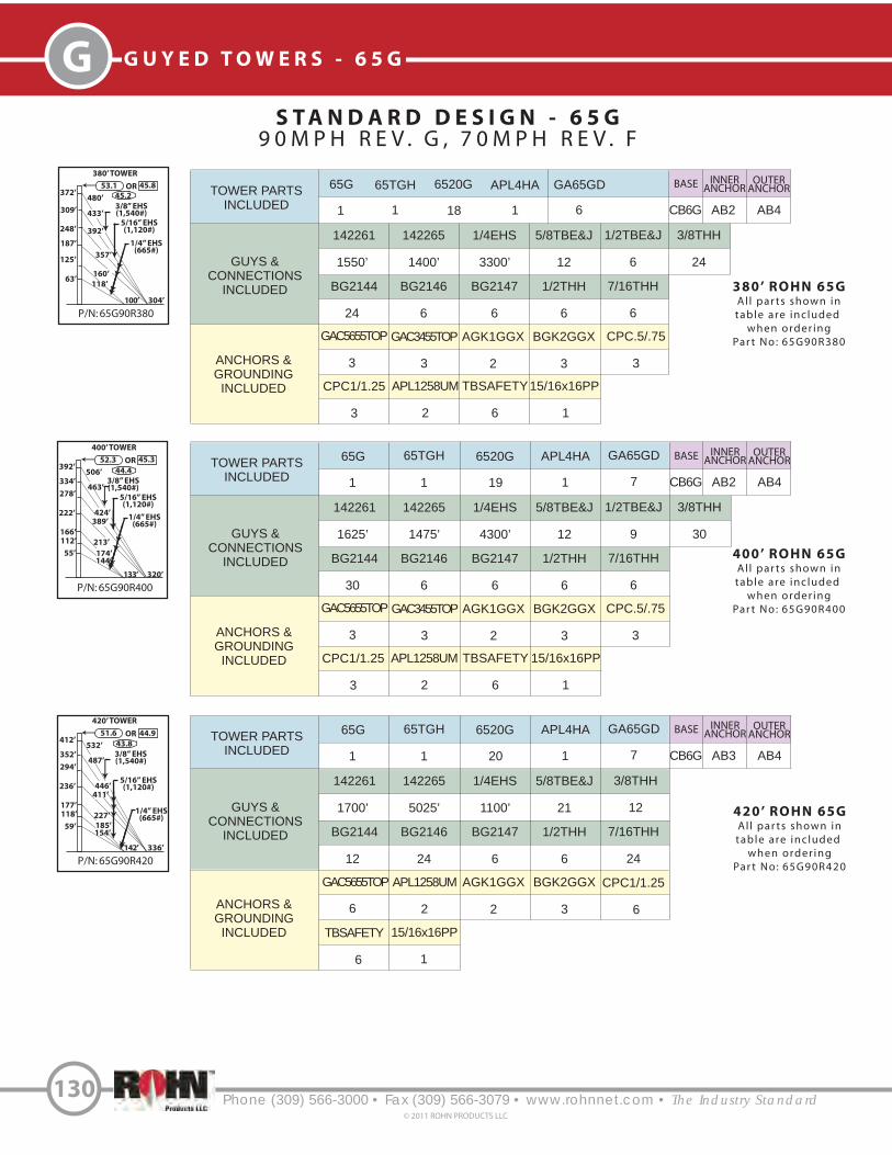
Phone (309) 566-3000 • Fax (309) 566-3079 • www.rohnnet.com • The Industry Standard
G G U Y E D T O W E R S - 6 5 G
S T A N D A R D D E S I G N - 6 5 G
9 0 M P H R E V . G , 7 0 M P H R E V . F
130© 2011 ROHN PRODUCTS LLC
P/N: 65G90R420
420’ TOWER
412’51.6 44.9OR
532’
336’
352’
59’
236’
142’
118’
154’
185’
227’
177’
487’294’
411’
446’5/16” EHS(1,120#)
1/4” EHS(665#)
3/8” EHS(1,540#)
P/N: 65G90R380
380’ TOWER
372’53.1 45.8OR
480’
304’
5/16” EHS(1,120#)
309’
63’
248’
187’
118’
160’
100’
125’357’
392’
433’
1/4” EHS(665#)
3/8” EHS(1,540#)
380’ ROHN 65G
Al l par ts shown intable are inc luded
when order ingPar t No: 65G90R380
45.2
P/N: 65G90R400
400’ TOWER
392’52.3 45.3OR
506’
320’
334’
55’
222’
133’
112’
144’
174’
213’
166’
463’278’
389’
424’
5/16” EHS(1,120#)
1/4” EHS(665#)
3/8” EHS(1,540#)
44.4
400’ ROHN 65G
Al l par ts shown intable are inc luded
when order ingPar t No: 65G90R400
43.8
420’ ROHN 65G
Al l par ts shown intable are inc luded
when order ingPar t No: 65G90R420
TOWER PARTS
INCLUDED
GUYS &
CONNECTIONS
INCLUDED
65G 65TGH 6520G APL4HA
BG2144 BG2146 BG2147
1 1 18 1
24 6 6
BASE
1/2THH
6
7/16THH
6
CB6G AB2
142261 142265 1/4EHS
1550’ 1400’ 3300’
5/8TBE&J
12
1/2TBE&J
6
GA65GD
6
ANCHORS &
GROUNDING
INCLUDED
GAC5655TOP AGK1GGX BGK2GGX
3 2 3
CPC.5/.75
33
INNERANCHOR
OUTERANCHOR
AB4
APL1258UM
2
GAC3455TOP
CPC1/1.25
3
3/8THH
24
TBSAFETY
6
TOWER PARTS
INCLUDED
GUYS &
CONNECTIONS
INCLUDED
65G 65TGH 6520G APL4HA
BG2144 BG2146 BG2147
1 1 19 1
30 6 6
BASE
1/2THH
6
7/16THH
6
CB6G AB2
142261 142265 1/4EHS
1625’ 1475’ 4300’
5/8TBE&J
12
1/2TBE&J
9
GA65GD
7
ANCHORS &
GROUNDING
INCLUDED
GAC5655TOP AGK1GGX BGK2GGX
3 2 3
CPC.5/.75
33
INNERANCHOR
OUTERANCHOR
AB4
APL1258UM
2
GAC3455TOP
CPC1/1.25
3
3/8THH
30
TBSAFETY
6
TOWER PARTS
INCLUDED
GUYS &
CONNECTIONS
INCLUDED
65G 65TGH 6520G APL4HA
BG2144 BG2146 BG2147
1 1 20 1
12 24 6
BASE
1/2THH
6
7/16THH
24
CB6G AB3
142261 142265 1/4EHS
1700’ 5025’ 1100’
5/8TBE&J
21
GA65GD
7
ANCHORS &
GROUNDING
INCLUDED
GAC5655TOP AGK1GGX BGK2GGX
6 2 32
INNERANCHOR
OUTERANCHOR
AB4
APL1258UM
3/8THH
12
CPC1/1.25
TBSAFETY
6
6
15/16x16PP
1
15/16x16PP
1
1
15/16x16PP

S T A N D A R D D E S I G N - 6 5 G
9 0 M P H R E V . G , 7 0 M P H R E V . F
Phone (309) 566-3000 • Fax (309) 566-3079 • www.rohnnet.com • The Industry Standard
GG U Y E D T O W E R S - 6 5 G
131© 2011 ROHN PRODUCTS LLC
P/N: 65G90R480
480’ TOWER
472’49.7 43.6OR
609’
384’
413’
59’
236’
142’
118’
154’
185’
227’
177’
564’
354’
484’
5/16” EHS(1,120#)
1/4” EHS(665#)
3/8” EHS(1,540#)
295’ 522’
451’
P/N: 65G90R460
460’ TOWER
448’50.3 44.0OR
580’
368’
392’
56’
224’
134’
112’
146’175’
215’
168’
538’
336’
5/16” EHS(1,120#)
1/4” EHS(665#)
3/8” EHS(1,540#)
280’ 498’
431’
462’
P/N: 65G90R440
440’ TOWER
428’50.9 44.4OR
554’
352’
368’
63’
248’
150’
126’
163’
196’
241’
188’
509’308’
431’
468’
5/16” EHS(1,120#)
1/4” EHS(665#)
3/8” EHS(1,540#)
440’ ROHN 65G
Al l par ts shown intable are inc luded
when order ingPar t No: 65G90R440
460’ ROHN 65G
Al l par ts shown intable are inc luded
when order ingPar t No: 65G90R460
480’ ROHN 65G
Al l par ts shown intable are inc luded
when order ingPar t No: 65G90R480
43.2
42.6
42.0
TOWER PARTS
INCLUDED
GUYS &
CONNECTIONS
INCLUDED
65G 65TGH 6520G APL4HA
BG2144 BG2146 BG2147
1 1 21 1
12 24 6
BASE
1/2THH
6
7/16THH
24
CB7G AB3
142261 142265 1/4EHS
1775’ 5275’ 1150’
5/8TBE&J
21
GA65GD
7
ANCHORS &
GROUNDING
INCLUDED
GAC5655TOP AGK1GGX BGK2GGX
6 2 32
INNERANCHOR
OUTERANCHOR
AB4
APL1258UM
3/8THH
12
CPC1/1.25
6
TOWER PARTS
INCLUDED
GUYS &
CONNECTIONS
INCLUDED
65G 65TGH 6520G APL4HA
BG2144 BG2146 BG2147
1 1 22 1
12 30 6
BASE
1/2THH
6
7/16THH
30
CB7G AB3
142261 142265 1/4EHS
1850’ 6850’ 1025’
3/4TBE&J
15
5/8TBE&J
9
GA65GD
8
ANCHORS &
GROUNDING
INCLUDED
GAC5655TOP AGK1GGX BGK2GGX
3 2 3
CPC1/1.25
33
INNERANCHOR
OUTERANCHOR
AB5
APL1258UM
2
GAC5755TOP
CPC1.5/2
3
3/8THH
12
TBSAFETY
6
TOWER PARTS
INCLUDED
GUYS &
CONNECTIONS
INCLUDED
65G 65TGH 6520G APL4HA
BG2144 BG2146 BG2147
1 1 23 1
12 30 6
BASE
1/2THH
6
7/16THH
30
CB7G AB3
142261 142265 1/4EHS
1950’ 7175’ 1100’
3/4TBE&J
15
5/8TBE&J
9
GA65GD
8
ANCHORS &
GROUNDING
INCLUDED
GAC5655TOP AGK1GGX BGK2GGX
3 2 3
CPC1/1.25
33
INNERANCHOR
OUTERANCHOR
AB5
APL1258UM
2
GAC5755TOP
CPC1.5/2
3
3/8THH
12
TBSAFETY
6
1
15/16x16PPTBSAFETY
6
15/16x16PP
1
15/16x16PP
1

Phone (309) 566-3000 • Fax (309) 566-3079 • www.rohnnet.com • The Industry Standard
G G U Y E D T O W E R S - 6 5 G
S T A N D A R D D E S I G N - 6 5 G
9 0 M P H R E V . G , 7 0 M P H R E V . F
132© 2011 ROHN PRODUCTS LLC
P/N: 65G90R500
500’ TOWER
488’49.1 43.3OR
631’
400’
427’
61’
244’
150’
122’
162’
193’
237’
183’
585’
366’
503’
5/16” EHS(1,120#)
1/4” EHS(665#)
3/8” EHS(1,540#)
305’ 542’
469’
500’ ROHN 65G
Al l par ts shown intable are inc luded
when order ingPar t No: 65G90R500
41.6TOWER PARTS
INCLUDED
GUYS &
CONNECTIONS
INCLUDED
65G 65TGH 6520G APL4HA
BG2144 BG2146 BG2147
1 1 24 1
12 30 6
BASE
1/2THH
6
7/16THH
30
CB7G AB3
142261 142265 1/4EHS
2025’ 7450’ 1150’
3/4TBE&J
15
5/8TBE&J
9
GA65GD
8
ANCHORS &
GROUNDING
INCLUDED
GAC5655TOP AGK1GGX BGK2GGX
3 2 3
CPC1/1.25
33
INNERANCHOR
OUTERANCHOR
AB5
APL1258UM
2
GAC5755TOP
CPC1.5/2
3
3/8THH
12
TBSAFETY
6
15/16x16PP
1

TOWER PARTS
INCLUDED
GUYS &
CONNECTIONS
INCLUDED
ANCHORS &
GROUNDING
INCLUDED
65G 65TGH 6520G APL4HA
142265 1/4EHS BG2144 BG2146 7/16THH
GAC5655TOP AGK1GGX BGK2GGX
1 1 5 1
475’ 375’ 6 6 6
3 1 3
FDNS
BASE ANCHOR
3/8THH
6 6
5/8TBE&J
CPC1/1.25
3
TBSAFETY
3
AB3
GA65GD
2
TOWER PARTS
INCLUDED
GUYS &
CONNECTIONS
INCLUDED
ANCHORS &
GROUNDING
INCLUDED
65TGH 6520G APL4HA GA65GD
142265 1/4EHS BG2144 BG2146 7/16THH
GAC3455TOP AGK1GGX BGK2GGX
1 5 1 2
425’ 325’ 6 6 6
3 1 3
FDNS
BASE ANCHOR
3/8THH
6 3
1/2TBE&J
3
5/8TBE&J
CPC.5/.75
3
TBSAFETY
3
AB2
P/N: 65G110R140
140’ TOWER
129’
47.2 37.9OR
171’
112’
3/16” EHS(399#)
141’
86’
43’ 120’
1/4” EHS(665#)
5/16” EHS(1,120#)
P/N: 65G110R130
130’ TOWER
120’
48.4 38.5OR
159’
104’
3/8” EHS(1,540#)
120’60’
1/4” EHS(665#)
P/N: 65G110R120
120’ TOWER
112’
49.5 39.2OR
148’
96’
5/16” EHS(1,120#)
111’55’
1/4” EHS(665#)
P/N: 65G110R110
110’ TOWER
100’
50.8 39.9OR
133’
88’
5/16” EHS(1,120#)
102’52’
1/4” EHS(665#)
P/N: 65G110R100
100’ TOWER
92’
52.2 40.7OR
122’
80’
5/16” EHS(1,120#)
92’45’
1/4” EHS(665#)
22.2
22.8
S T A N D A R D D E S I G N - 6 5 G
1 1 0 M P H R E V . G , 9 0 M P H R E V . F
Phone (309) 566-3000 • Fax (309) 566-3079 • www.rohnnet.com • The Industry Standard
GG U Y E D T O W E R S - 6 5 G
133© 2011 ROHN PRODUCTS LLC
100’ ROHN 65G
All parts shown in
table are included
when ordering
Part No: 65G110R100
110’ ROHN 65G
All parts shown in
table are included
when ordering
Part No: 65G110R110
120’ ROHN 65G
All parts shown in
table are included
when ordering
Part No: 65G110R120
TOWER PARTS
INCLUDED
GUYS &
CONNECTIONS
INCLUDED
ANCHORS &
GROUNDING
INCLUDED
65TGH 6520G APL4HA GA65GD
142261 1/4EHS BG2147 BG2144 1/2THH
AGK1GGX BGK2GGX
1 6 1 2
525’ 400’ 6 6 6
3 1 3
130’ ROHN 65G
All parts shown in
table are included
when ordering
Part No: 65G110R130
FDNS
BASE ANCHOR
3/8THH
6 6
5/8TBE&J
140’ ROHN 65G
All parts shown in
table are included
when ordering
Part No: 65G110R140
TBSAFETY
3
CPC1/1.25
3
CB2G AB3
24.2
23.6
21.6
TOWER PARTS
INCLUDED
GUYS &
CONNECTIONS
INCLUDED
ANCHORS &
GROUNDING
INCLUDED
65G 65TGH 6520G APL4HA
142265 1/4EHS BG2144 BG2146 7/16THH
GAC3455TOP AGK1GGX BGK2GGX
1 1 4 1
400’ 300’ 6 6 6
3 1 3
FDNS
BASE ANCHOR
3/8THH
6 3
1/2TBE&J
3
5/8TBE&J
CPC.5/.75
3
TBSAFETY
3
AB2
GA65GD
2
GAC5655TOP
TOWER PARTS
INCLUDED
GUYS &
CONNECTIONS
INCLUDED
65G 65TGH 6520G APL4HA
BG2146 5/8TBE&J 7/16THH
1 1 6 1
6 9 6
FDNS
BASE ANCHOR
3/8THH
6
5/16THH
6
CB3G AB3
ANCHORS &
GROUNDING
INCLUDED
GAC5655TOP AGK1GGX BGK2GGX
3 1 3
CPC1/1.25
3
TBSAFETY
3
142265 1/4EHS 3/16EHS
550’ 450’ 400’
BG2142
6
BG2144
6
GA65GD
3
CB2G
CB2G
CB2G
15/16x16PP
1
15/16x16PP
1
15/16x16PP
1
15/16x16PP
1
15/16x16PP
1

P/N: 65G110R180
180’ TOWER
168’
44.1 35.9OR
221’
144’
1/4” EHS(665#)
182’
112’
56’ 155’
3/8” EHS(1,540#)
P/N: 65G110R170
170’ TOWER
159’
44.8 36.4OR
209’
136’
172’
106’
53’ 146’
3/8” EHS(1,540#)
1/4” EHS(665#)
P/N: 65G110R160
160’ TOWER
152’
45.6 36.8OR
199’
128’
3/16” EHS(399#)
162’
100’
52’ 138’
3/8” EHS(1,540#)
1/4” EHS(665#)
P/N: 65G110R150
150’ TOWER
138’
46.4 37.3OR
183’
120’
3/16” EHS(399#)
151’
92’
46’ 129’
3/8” EHS(1,540#)
1/4” EHS(665#)
20.2
Phone (309) 566-3000 • Fax (309) 566-3079 • www.rohnnet.com • The Industry Standard
G G U Y E D T O W E R S - 6 5 G
S T A N D A R D D E S I G N - 6 5 G
1 1 0 M P H R E V . G , 9 0 M P H R E V . F
134© 2011 ROHN PRODUCTS LLC
150’ ROHN 65G
All parts shown in
table are included
when ordering
Part No: 65G110R150
160’ ROHN 65G
All parts shown in
table are included
when ordering
Part No: 65G110R160
170’ ROHN 65G
All parts shown in
table are included
when ordering
Part No: 65G110R170
TOWER PARTS
INCLUDED
GUYS &
CONNECTIONS
INCLUDED
ANCHORS &
GROUNDING
INCLUDED
65G 65TGH 6520G APL4HA
142261 1/4EHS BG2144 BG2147 1/2THH
GAC5655TOP AGK1GGX BGK2GGX
1 1 8 1
725’ 1075’ 12 6 6
3 1 3
180’ ROHN65G
All parts shown in
table are included
when ordering
Part No: 65G110R180
FDNS
BASE ANCHOR
3/8THH
12 9
5/8TBE&J
CPC1/1.25
3
TBSAFETY
3
CB3G AB3
21.2
20.6
19.8
TOWER PARTS
INCLUDED
GUYS &
CONNECTIONS
INCLUDED
ANCHORS &
GROUNDING
INCLUDED
65TGH 6520G APL4HA GA65GD
GAC5655TOP BGK2GGX CPC1/1.25
1 7 1 3
63 3
142261
600’
BG2147
6
1/4EHS
500’
5/8TBE&J
9
3/16EHS
425’
1/2THH
6
BG2142
6
3/8THH
6
BG2144
6
5/16THH
6
AGK1GGX
1
TBSAFETY
3
CB3G AB3
FDNS
BASE ANCHOR
TOWER PARTS
INCLUDED
GUYS &
CONNECTIONS
INCLUDED
65G 65TGH 6520G APL4HA
BG2147 5/8TBE&J 1/2THH
1 1 7 1
6 9 6
FDNS
BASE ANCHOR
3/8THH
6
5/16THH
6
CB3G AB3
ANCHORS &
GROUNDING
INCLUDED
GAC5655TOP AGK1GGX BGK2GGX
3 1 3
CPC1/1.25
3
TBSAFETY
3
142261 1/4EHS 3/16EHS
650’ 525’ 450’
BG2142
6
BG2144
6
GA65GD
3
TOWER PARTS
INCLUDED
GUYS &
CONNECTIONS
INCLUDED
ANCHORS &
GROUNDING
INCLUDED
65TGH 6520G APL4HA GA65GD
142261 1/4EHS BG2144 BG2147 1/2THH
GAC5655TOP AGK1GGX BGK2GGX
1 8 1 3
675’ 1025’ 12 6 6
3 1 3
FDNS
BASE ANCHOR
3/8THH
12 9
5/8TBE&J
CPC1/1.25
3
TBSAFETY
3
CB3G AB3
GA65GD
3
15/16x16PP
1
15/16x16PP
1
15/16x16PP
1
15/16x16PP
1

P/N: 65G110R240
240’ TOWER
232’
40.6 33.8OR
301’
192’
258’
173’
58’ 201’
116’224’ 1/4” EHS
(665#)
5/16” EHS(1,120#)
3/8” EHS(1,540#)
P/N: 65G110R220
220’ TOWER
208’
41.6 34.4OR
272’
176’
235’
156’
52’ 184’
104’204’ 1/4” EHS
(665#)
5/16” EHS(1,120#)
3/8” EHS(1,540#)
P/N: 65G110R200
200’ TOWER
186’
42.7 35.1OR
245’
160’
1/4” EHS(665#)
202’
124’
62’ 172’
5/16” EHS(1,120#)
Phone (309) 566-3000 • Fax (309) 566-3079 • www.rohnnet.com • The Industry Standard
GG U Y E D T O W E R S - 6 5 G
S T A N D A R D D E S I G N - 6 5 G
1 1 0 M P H R E V . G , 9 0 M P H R E V . F
135© 2011 ROHN PRODUCTS LLC
200’ ROHN 65G
Al l par ts shown in
table are inc luded
when order ing
Par t No: 65G110R200
220’ ROHN 65G
Al l par ts shown in
table are inc luded
when order ing
Par t No: 65G110R220
240’ ROHN 65G
Al l par ts shown in
table are inc luded
when order ing
Par t No: 65G110R240
17.0
16.4
15.8
P/N: 65G110R190
190’ TOWER
180’
43.4 35.5OR
236’
152’
1/4” EHS(665#)
194’
120’
60’ 163’
3/8” EHS(1,540#)
5/16” EHS(1,120#)
190’ ROHN 65G
Al l par ts shown in
table are inc luded
when order ing
Par t No: 65G110R190
19.4TOWER PARTS
INCLUDED
GUYS &
CONNECTIONS
INCLUDED
ANCHORS &
GROUNDING
INCLUDED
65TGH 6520G APL4HA GA65GD
GAC5655TOP BGK2GGX CPC1/1.25
1 9 1 3
63 3
142261
750’
BG2147
6
142265
625’
5/8TBE&J
9
1/4EHS
525’
1/2THH
6
BG2144
6
7/16THH
6
BG2146
6
3/8THH
6
AGK1GGX
1
TBSAFETY
3
CB4G AB4
FDNS
BASE ANCHOR
TOWER PARTS
INCLUDED
GUYS &
CONNECTIONS
INCLUDED
65G 65TGH 6520G APL4HA
BG2147 5/8TBE&J 1/2THH
1 1 9 1
6 9 6
FDNS
BASE ANCHOR
7/16THH
6
3/8THH
6
CB4G AB4
ANCHORS &
GROUNDING
INCLUDED
GAC5655TOP AGK1GGX BGK2GGX
3 1 3
CPC1/1.25
3
TBSAFETY
3
142261 142265 1/4EHS
800’ 650’ 550’
BG2144
6
BG2146
6
GA65GD
33/8” EHS(1,540#)
TOWER PARTS
INCLUDED
GUYS &
CONNECTIONS
INCLUDED
65G 65TGH 6520G APL4HA
BG2147 5/8TBE&J 1/2THH
1 1 10 1
6 12 6
FDNS
BASE ANCHOR
7/16THH
6
3/8THH
12
CB4G AB4
ANCHORS &
GROUNDING
INCLUDED
GAC5655TOP AGK1GGX BGK2GGX
3 1 3
CPC1/1.25
3
TBSAFETY
3
142261 142265 1/4EHS
875’ 750’ 1250’
BG2144
12
BG2146
6
GA65GD
4
TOWER PARTS
INCLUDED
GUYS &
CONNECTIONS
INCLUDED
65G 65TGH 6520G APL4HA
BG2147 5/8TBE&J 1/2THH
1 1 11 1
6 12 6
FDNS
BASE ANCHOR
7/16THH
6
3/8THH
12
CB4G AB4
ANCHORS &
GROUNDING
INCLUDED
GAC5655TOP AGK1GGX BGK2GGX
3 1 3
CPC1/1.25
3
TBSAFETY
3
142261 142265 1/4EHS
975’ 825’ 1375’
BG2144
12
BG2146
6
GA65GD
4
15/16x16PP
1
15/16x16PP
1
15/16x16PP
1
15/16x16PP
1

P/N: 65G110R320
320’ TOWER
312’37.3 31.8OR
404’
256’
356’
248’
62’
186’
316’
5/16” EHS(1,120#)
284’
263’
124’
1/4” EHS(665#)
3/8” EHS(1,540#)
P/N: 65G110R300
300’ TOWER
292’38.0 32.3OR
378’
240’
334’
232’
58’
174’
296’
267’
247’
116’ 1/4” EHS(665#)
5/16” EHS(1,120#)
3/8” EHS(1,540#)
P/N: 65G110R280
280’ TOWER
272’38.8 32.7OR
352’
224’
311’
216’
54’
162’
276’
1/4” EHS(665#)
249’
230’
108’
5/16” EHS(1,120#)
3/8” EHS(1,540#)
Phone (309) 566-3000 • Fax (309) 566-3079 • www.rohnnet.com • The Industry Standard
G G U Y E D T O W E R S - 6 5 G
S T A N D A R D D E S I G N - 6 5 G
1 1 0 M P H R E V . G , 9 0 M P H R E V . F
136© 2011 ROHN PRODUCTS LLC
280’ ROHN 65G
Al l par ts shown in
table are inc luded
when order ing
Par t No: 65G110R280
300’ ROHN 65G
Al l par ts shown in
table are inc luded
when order ing
Par t No: 65G110R300
320’ ROHN 65G
Al l par ts shown in
table are inc luded
when order ing
Par t No: 65G110R320
14.8
14.4
14.0
TOWER PARTS
INCLUDED
GUYS &
CONNECTIONS
INCLUDED
ANCHORS &
GROUNDING
INCLUDED
65G 65TGH 6520G APL4HA
BGK2GGX CPC1.5/2
1 1 13 1
63
142261
1125’
7/16THH
6
142265
1000’
3/4TBE&J
15
BG2144
18
3/8THH
18
BG2146
6
1/2THH
6
BG2147
6
1/4EHS
2450’
AGK1GGX
13
CB5G AB5
TOWER PARTS
INCLUDED
GUYS &
CONNECTIONS
INCLUDED
ANCHORS &
GROUNDING
INCLUDED
65G 65TGH 6520G APL4HA
BGK2GGX CPC1.5/2
1 1 14 1
33
142261
1225’
BG2147
6
142265
2875’
3/4TBE&J
15
1/4EHS
800’
1/2THH
6
BG2144
6
7/16THH
18
BG2146
18
3/8THH
6
AGK1GGX
13
TOWER PARTS
INCLUDED
GUYS &
CONNECTIONS
INCLUDED
ANCHORS &
GROUNDING
INCLUDED
65G 65TGH 6520G APL4HA
BGK2GGX CPC1.5/2
1 1 15 1
33
142261
2425’
BG2147
12
142265
1925’
3/4TBE&J
15
BG2144
6
1/2THH
12
BG2146
12
7/16THH
12
3/8THH
6
AGK1GGX
13
1/4EHS
850’
P/N: 65G110R260
260’ TOWER
248’
39.6 33.2OR
324’
208’
279’186’
62’ 217’
124’242’
1/4” EHS(665#)
3/8” EHS(1,540#)
5/16” EHS(1,120#)
260’ ROHN 65G
Al l par ts shown in
table are inc luded
when order ing
Par t No: 65G110R260
TOWER PARTS
INCLUDED
GUYS &
CONNECTIONS
INCLUDED
ANCHORS &
GROUNDING
INCLUDED
65G 65TGH 6520G APL4HA
GAC5755TOP BGK2GGX CPC1.5/2
1 1 12 1
33 3
142261
1050’
7/16THH
12
142265
1675’
3/4TBE&J
12
1/4EHS
700’
3/8THH
6
BG2144
6
BG2146
12
1/2THH
6
BG2147
6
AGK1GGX
1
CB5G AB5
15.2
GA65GD
4
TBSAFETY
3
FDNS
BASE ANCHOR
FDNS
BASE ANCHORGA65GD
5
GAC5755TOP TBSAFETY
3
CB5G AB5
FDNS
BASE ANCHORGA65GD
5
GAC5755TOP TBSAFETY
3
CB6G AB6
FDNS
BASE ANCHORGA65GD
5
GAC5755TOP TBSAFETY
3
15/16x16PP
1
15/16x16PP
1
15/16x16PP
1
15/16x16PP
1

S T A N D A R D D E S I G N - 6 5 G
1 1 0 M P H R E V . G , 9 0 M P H R E V . F
Phone (309) 566-3000 • Fax (309) 566-3079 • www.rohnnet.com • The Industry Standard
GG U Y E D T O W E R S - 6 5 G
137© 2011 ROHN PRODUCTS LLC
P/N: 65G110R340
340’ TOWER
332’36.7 31.4OR
429’
272’
275’
55’
220’
165’
104’
142’
1/4” EHS(665#)
88’
112’318’
350’
387’
5/16” EHS(1,120#)
3/8” EHS(1,540#)
340’ ROHN 65G
Al l par ts shown intable are inc luded
when order ingPar t No: 65G110R340
13.6TOWER PARTS
INCLUDED
GUYS &
CONNECTIONS
INCLUDED
ANCHORS &
GROUNDING
INCLUDED
65G 65TGH 6520G APL4HA
GAC5755TOP BGK2GGX
CPC1/1.25
1 1 16 1
3
3 3
142261
2600’
3/4TBE&J
12
1/4EHS
350’
5/8TBE&J
6
BG2144
6
1/2THH
12
BG2146
18
7/16THH
18
BG2147
12
3/8THH
6
AGK1GGX
23
BASE INNERANCHOR
CB7G
OUTERANCHOR
AB5AB3
142265
2600’
GA65GD
6
GAC5655TOP
TBSAFETY
63
CPC1.5/2 15/16x16PP
1
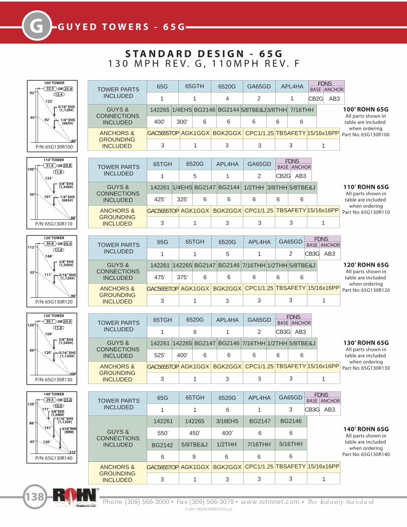
Phone (309) 566-3000 • Fax (309) 566-3079 • www.rohnnet.com • The Industry Standard
G G U Y E D T O W E R S - 6 5 G
138© 2011 ROHN PRODUCTS LLC
P/N: 65G130R130
130’ TOWER
120’
30.1 24.0OR
159’
104’
3/8” EHS(1,540#)
120’60’
5/16” EHS(1,120#)
11.0
P/N: 65G130R120
120’ TOWER
112’
30.8 24.4OR
148’
96’
3/8” EHS(1,540#)
111’55’
5/16” EHS(1,120#)
11.4
S T A N D A R D D E S I G N - 6 5 G
1 3 0 M P H R E V . G , 1 1 0 M P H R E V . F
P/N: 65G130R100
100’ TOWER
92’
32.5 25.4OR
122’
80’
5/16” EHS(1,120#)
92’45’
1/4” EHS(665#)
P/N: 65G130R110
110’ TOWER
100’
31.6 24.8OR
133’
88’
3/8” EHS(1,540#)
101’50’
1/4” EHS(665#)
P/N: 65G130R140
140’ TOWER
129’
29.5 23.6OR
171’
112’
5/16” EHS(1,120#)
141’
86’
43’ 120’
3/16” EHS(399#)
TOWER PARTS
INCLUDED
GUYS &
CONNECTIONS
INCLUDED
ANCHORS &
GROUNDING
INCLUDED
65G 65GTH 6520G GA65GD
142265 1/4EHS BG2146 BG2144 5/8TBE&J
AGK1GGX BGK2GGX
1 1 4 2
400’ 300’ 6 6 6
1 3
100’ ROHN 65G
All parts shown in
table are included
when ordering
Part No: 65G130R100
FDNS
BASE ANCHOR
3/8THH
6 6
7/16THH
TOWER PARTS
INCLUDED
GUYS &
CONNECTIONS
INCLUDED
ANCHORS &
GROUNDING
INCLUDED
65TGH 6520G APL4HA GA65GD
142261 1/4EHS BG2147 BG2144 1/2THH
AGK1GGX BGK2GGX
1 5 1 2
425’ 325’ 6 6 6
3 1 3
110’ ROHN 65G
All parts shown in
table are included
when ordering
Part No: 65G130R110
FDNS
BASE ANCHOR
3/8THH
6 6
5/8TBE&J
TOWER PARTS
INCLUDED
GUYS &
CONNECTIONS
INCLUDED
ANCHORS &
GROUNDING
INCLUDED
65G 65TGH 6520G APL4HA
142261 142265 BG2147 BG2146 7/16THH
AGK1GGX BGK2GGX
1 1 5 1
475’ 375’ 6 6 6
3 1 3
120’ ROHN 65G
All parts shown in
table are included
when ordering
Part No: 65G130R120
FDNS
BASE ANCHOR
1/2THH
6 6
5/8TBE&J
TOWER PARTS
INCLUDED
GUYS &
CONNECTIONS
INCLUDED
ANCHORS &
GROUNDING
INCLUDED
65TGH 6520G APL4HA GA65GD
142261 142265 BG2147 BG2146 7/16THH
AGK1GGX BGK2GGX
1 6 1 2
525’ 400’ 6 6 6
3 1 3
130’ ROHN 65G
All parts shown in
table are included
when ordering
Part No: 65G130R130
FDNS
BASE ANCHOR
1/2THH
6 6
5/8TBE&J
140’ ROHN 65G
All parts shown in
table are included
when ordering
Part No: 65G130R140
CPC1/1.25
3
TBSAFETY
3
TBSAFETY
3
CPC1/1.25
3
TBSAFETY
3
CPC1/1.25
3
TBSAFETY
3
CPC1/1.25
3
CB2G AB3
CB2G AB3
CB3G AB3
CB3G AB3
12.4
11.8
10.6
3/8” EHS(1,540#)
APL4HA
1
GAC5655TOP
3
GAC5655TOP
GA65GD
2
GAC5655TOP
GAC5655TOP
TOWER PARTS
INCLUDED
GUYS &
CONNECTIONS
INCLUDED
65G 65TGH 6520G APL4HA
142261 142265 BG2147 BG2146
BG2142 1/2THH 7/16THH
1 1 6 1
550’ 450’ 6 6
6 9 6 6
FDNS
BASE ANCHOR
5/16THH
6
CB3G AB3
GA65GD
3
5/8TBE&J
ANCHORS &
GROUNDING
INCLUDED
AGK1GGX BGK2GGX
3 1 3
TBSAFETY
3
CPC1/1.25
3
GAC5655TOP
3/16EHS
400’
15/16x16PP
1
15/16x16PP
1
15/16x16PP
1
15/16x16PP
1
15/16x16PP
1

Phone (309) 566-3000 • Fax (309) 566-3079 • www.rohnnet.com • The Industry Standard
GG U Y E D T O W E R S - 6 5 G
139© 2011 ROHN PRODUCTS LLC
P/N: 65G130R180
180’ TOWER
168’
27.4 22.4OR
221’
144’
182’
112’
56’ 155’
3/8” EHS(1,540#)
5/16” EHS(1,120#)
P/N: 65G130R170
170’ TOWER
159’
27.8 22.7OR
209’
136’
5/16” EHS(1,120#)
172’
106’
53’ 146’
1/4” EHS(665#)
9.6
S T A N D A R D D E S I G N - 6 5 G
1 3 0 M P H R E V . G , 1 1 0 M P H R E V . F
P/N: 65G130R150
150’ TOWER
138’
28.9 23.3OR
183’
120’
5/16” EHS(1,120#)
151’
92’
46’ 129’
3/16” EHS(399#)
P/N: 65G130R160
160’ TOWER
152’
28.4 22.9OR
199’
128’
5/16” EHS(1,120#)
162’
100’
52’ 138’
1/4” EHS(665#)
150’ ROHN 65G
Al l par ts shown in
table are inc luded
when order ing
Par t No: 65G130R150
160’ ROHN 65G
Al l par ts shown in
table are inc luded
when order ing
Par t No: 65G130R160
170’ ROHN 65G
Al l par ts shown in
table are inc luded
when order ing
Par t No: 65G130R170
180’ ROHN 65G
Al l par ts shown in
table are inc luded
when order ing
Par t No: 65G90R180
10.2
9.8
9.4
3/8” EHS(1,540#)
3/8” EHS(1,540#)
3/8” EHS(1,540#)
TOWER PARTS
INCLUDED
GUYS &
CONNECTIONS
INCLUDED
65TGH 6520G APL4HA
142261 142265 BG2147 BG2146
BG2142 1/2THH 7/16THH
1 7 1
600’ 500’ 6 6
6 9 6 6
FDNS
BASE ANCHOR
5/16THH
6
CB3G AB4
GA65GD
3
5/8TBE&J
ANCHORS &
GROUNDING
INCLUDED
AGK1GGX BGK2GGX
3 1 3
TBSAFETY
3
CPC1/1.25
3
GAC5655TOP
3/16EHS
425’
TOWER PARTS
INCLUDED
GUYS &
CONNECTIONS
INCLUDED
65G 65TGH 6520G APL4HA
142261 142265 BG2147 BG2146
BG2144 1/2THH 7/16THH
1 1 7 1
650’ 525’ 6 6
6 9 6 6
FDNS
BASE ANCHOR
3/8THH
6
CB4G AB4
GA65GD
3
5/8TBE&J
ANCHORS &
GROUNDING
INCLUDED
AGK1GGX BGK2GGX
3 1 3
TBSAFETY
3
CPC1/1.25
3
GAC5655TOP
1/4EHS
450’
TOWER PARTS
INCLUDED
GUYS &
CONNECTIONS
INCLUDED
65TGH 6520G APL4HA
142261 142265 BG2147 BG2146
BG2144 1/2THH 7/16THH
1 8 1
675’ 550’ 6 6
6 9 6 6
FDNS
BASE ANCHOR
3/8THH
6
CB4G AB4
GA65GD
3
5/8TBE&J
ANCHORS &
GROUNDING
INCLUDED
AGK1GGX BGK2GGX
3 1 3
TBSAFETY
3
CPC1/1.25
3
GAC5655TOP
1/4EHS
475’
TOWER PARTS
INCLUDED
GUYS &
CONNECTIONS
INCLUDED
65G 65TGH 6520G APL4HA
142261 142265 BG2147 BG2146
5/8TBE&J 7/16THH
1 1 8 1
725’ 1075’ 6 12
9 6 12
FDNS
BASE ANCHOR
CB4G AB4
GA65GD
3
1/2THH
ANCHORS &
GROUNDING
INCLUDED
AGK1GGX BGK2GGX
3 1 3
TBSAFETY
3
CPC1/1.25
3
GAC5655TOP
15/16x16PP
1
15/16x16PP
1
15/16x16PP
1
15/16x16PP
1

Phone (309) 566-3000 • Fax (309) 566-3079 • www.rohnnet.com • The Industry Standard
G G U Y E D T O W E R S - 6 5 G
140© 2011 ROHN PRODUCTS LLC
S T A N D A R D D E S I G N - 6 5 G
1 3 0 M P H R E V . G , 1 1 0 M P H R E V . F
P/N: 65G130R190
190’ TOWER
180’
27.0 22.1OR
236’
152’
194’
120’
60’ 163’
3/8” EHS(1,540#)
5/16” EHS(1,120#)
190’ ROHN 65G
Al l par ts shown in
table are inc luded
when order ing
Par t No: 65G130R190
9.0
TOWER PARTS
INCLUDED
GUYS &
CONNECTIONS
INCLUDED
ANCHORS &
GROUNDING
INCLUDED
65TGH 6520G APL4HA GA65GD
142261 142265 BG2147 BG2146 7/16THH
AGK1GGX BGK2GGX
1 9 1 3
750’ 1150’ 6 12 12
3 1 3
FDNS
BASE ANCHOR
1/2THH
6 9
5/8TBE&J
TBSAFETY
3
CPC1/1.25
3
CB4G AB4
GAC5655TOP 15/16x16PP
1

Phone (309) 566-3000 • Fax (309) 566-3079 • www.rohnnet.com • The Industry Standard
GG U Y E D T O W E R S - 6 5 G
141© 2011 ROHN PRODUCTS LLC
P A R T S & A C C E S S O R I E S
5’ SHORT BASE
SB65GHFOR EMBEDMENT IN CONCRETE.
SIDE ARM ASSEMBLY
SA253UAMOUNTING TUBE PROVIDED IS 3’ LONG,
2 1/4” O.D.
HOUSE BRACKET
KH1014ADJUSTABLE TO POSITION 65G
18” - 30” FROM WALL.
FACE DISH MOUNT
DM6544 1/2” O.D. X 5’ LONG
DM654TB4 1/2” O.D. X 5’ LONG WITH TIE-BACK
ANGLE.
10’ TAPERED BASE
65TGH*FOR USE WITH 15/16X16PP, ORDERED SEPARATELY.
CAP PLATE KIT
CP4A(3) CAP PLATES WITH NUTS AND BOLTS.
LIGHTNING ROD
PLATE KIT
VW133INCLUDES: LIGHTNING ROD PLATE,(2) CAP PLATES, NUTS AND BOLTS.
PIER PIN
15/16X16PPFOR USE WITH 65TGH
EMBEDDED IN CONCRETE.
PIER PIN MUST BE ORDEREDSEPARATELY, UNLESS BEINGPURCHASED AS PART OFA COMPLETE TOWER KIT.
LEG MOUNTED
BEACON PLATE KIT
APL4HAFOR MOUNTING BEACON ORLIGHTNING ROD. BOLTS TO TOP OF STANDARD SECTION. INCLUDES BEACON PLATE,
(2) CAP PLATES, NUTS AND BOLTS.
LIGHTNING ROD
LRCL5’ COPPER CLAD
ORDERED SEPARATELY.
* TOWERS MOUNTED ON THESE BASES MUST BE BRACKETED OR GUYED AT ALL TIMES. TEMPORARY STEEL GUYING MAY ALSO BE NECESSARY DURING INSTALLATION AND DISMANTLING.
Adjustable
2.5’ - 3.0’
Tie-Back Anglewith 9/16” dia.holes, includedwith DM654TB.
6.2’
DISH MOUNT
KY509 - 2 3/8” O.D. MASTKY510 - 4 1/2” O.D. MAST
MOUNTING TUBE PROVIDED IS 5’ LONG.
3’ SIDE ARM
KH6100AMOUNTING TUBE PROVIDED IS 7’ LONG,
2 3/8” O.D.
6’ SIDE ARM
KY1048AMOUNTING TUBE PROVIDED IS 5’ LONG,
2 3/8” O.D.

P A R T S & A C C E S S O R I E S
Phone (309) 566-3000 • Fax (309) 566-3079 • www.rohnnet.com • The Industry Standard
G G U Y E D T O W E R S - 6 5 G
142© 2011 ROHN PRODUCTS LLC
CLIMBING HARNESS
TTFBH-4DJOURNEYMAN HARNESS
TTFBH-C/PPROFESSIONAL HARNESS
SAFETY CABLE SYSTEM
ORDERING INFORMATION
TOWER HEIGHT
50’
100’
150’
200’
250’
300’
350’
400’
450’
500’
PARTNUMBER
TT05065
TT10065
TT15065
TT20065
TT25065
TT30065
TT35065
TT40065
TT45065
TT50065SAFETY CABLE
SLIDER WITH CARABINEER
TT-WG-500-W/SMC
GUY BRACKET ASSEMBLY
GA65GDKIT INCLUDES (3) BRACKETS WITH
U-BOLTS.
WORK PLATFORM
WPCC65SNAPS INTO PLACE AT ANY LEVEL.
NO BOLTS REQUIRED.
ANTI-CLIMB PANELS
VW915ATHREE ANTI-CLIMB PANELS BOLT TO STANDARD TOWER SECTION.
SAFETY CABLE SLIDER ANDCLIMBING HARNESS MUST BE
ORDERED SEPARATELY.

Phone (309) 566-3000 • Fax (309) 566-3079 • www.rohnnet.com • The Industry Standard
GG U Y E D T O W E R S - 6 5 G
143© 2011 ROHN PRODUCTS LLC
REV G
ANCHOR GROUNDING
AGK1GGX
REV G
BASE GROUNDING
BGK2GGX
A N C H O R I N F O R M A T I O N
3/8”
2”
12”
3/4”P/N STAMPED HERE
GAC3455TOP
1/2”
2 1/2”
12”
120”
1 1/4”P/N STAMPED HERE
GAC5655TOP
81”
3/4”
3”
12”
168”
1 7/16”P/N STAMPED HERE
GAC5755TOP
11/16”
13/16”
15/16”
4” x 4” x 3/8” angle
5” x 5” x 3/8” angle
CL of hole to edgeof plate = 1 1/4”
CL of hole to edgeof plate = 1”
CL of hole to edgeof plate = 1 1/4”
5” x 5” x 3/8” angle
Ground Wire
Ground Rod Clamp
Ground Rod
Clamp
6” Min.
Attach to leg withsupplied leg clamp
Ground Wire
6” Min.Ground Rod Clamp
Ground Rod,3 provided (to be installed
at 120 separation at 20’ spacing.o

G G U Y E D T O W E R S - 6 5 G
Phone (309) 566-3000 • Fax (309) 566-3079 • www.rohnnet.com • The Industry Standard144
© 2011 ROHN PRODUCTS LLC
All around stirrupsequally spaced 12” O.C. anchored with 90hooks around a horizontal bar
Top and bottom horizontal bars equally spaced
C
B
A
Ground Line
D
Anchor rod
o
Additional bar atcenter-line eachside, when required
S T A N D A R D A N C H O R B L O C K S
Block
AB2
AB3
AB4
AB5
AB6
A
4’ - 0”
6’ - 0”
6‘ - 0”
8’ - 0”
8’ - 0”
Concrete Vol.(Cu. Yds.)
1.33 Per Block4.0 Total for 3
1.0 Per Block3.0 Total for 3
2.0 Per Block6.0 Total for 3
2.22 Per Block6.7 Total for 3
2.96 Per Block8.9 Total for 3
B
1‘ - 6”
1’ - 6”
1’ - 6”
2’ - 0”
2’ - 0”
C
4‘ - 0“
3’ - 0”
4‘ - 0“
3’ - 0”
4’ - 0”
Horizontal Bars(Qty. & Size)
(5) #6 Bars, Top Layer(5) #6 Bars, Bottom Layer(0) Additional Bar, Each Side
(4) #6 Bars, Top Layer(4) #6 Bars, Bottom Layer(0) Additional Bar, Each Side
(5) #6 Bars, Top Layer(5) #6 Bars, Bottom Layer(0) Additional Bar, Each Side
(4) #7 Bars, Top Layer(4) #7 Bars, Bottom Layer(1) Additional Bar, Each Side
(5) #7 Bars, Top Layer(5) #7 Bars, Bottom Layer(1) Additional Bar, Each Side
D
6’ - 0”
6’ - 0”
9’ - 0”
10’ - 0”
10’ - 0”
Anchor Dimensions (in.) Stirrup Size& Spacing
#3 @ 12” O.C.
#3 @ 12” O.C.
#4 @ 12” O.C.
#4 @ 12” O.C.
#4 @ 12” O.C.
Refer to page 145 for anchor rod installation angles.
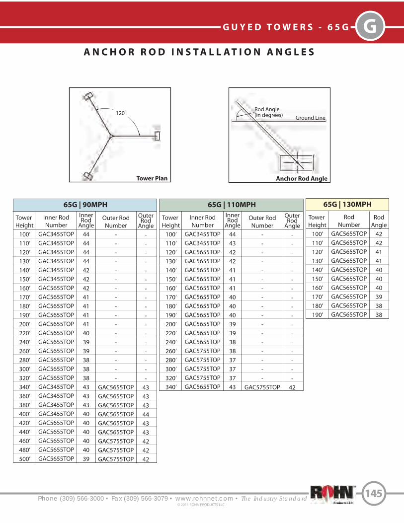
Phone (309) 566-3000 • Fax (309) 566-3079 • www.rohnnet.com • The Industry Standard
GG U Y E D T O W E R S - 6 5 G
145© 2011 ROHN PRODUCTS LLC
A N C H O R R O D I N S T A L L A T I O N A N G L E S
120o
Ground Line
Rod Angle(in degrees)
Tower
Height
100’
110’
120’
130’
140’
150’
160’
170’
180’
190’
200’
220’
240’
260’
280’
300’
320’
340’
360’
380’
400’
420’
440’
460’
480’
500’
Inner Rod
Number
GAC3455TOP
GAC3455TOP
GAC3455TOP
GAC3455TOP
GAC3455TOP
GAC3455TOP
GAC5655TOP
GAC5655TOP
GAC5655TOP
GAC5655TOP
GAC5655TOP
GAC5655TOP
GAC5655TOP
GAC5655TOP
GAC5655TOP
GAC5655TOP
GAC5655TOP
GAC3455TOP
GAC3455TOP
GAC3455TOP
GAC3455TOP
GAC5655TOP
GAC5655TOP
GAC5655TOP
GAC5655TOP
GAC5655TOP
InnerRod
Angle
44
44
44
44
42
42
42
41
41
41
41
40
39
39
38
38
38
43
43
43
40
40
40
40
40
39
65G | 90MPH
Outer Rod
Number
-
-
-
-
-
-
-
-
-
-
-
-
-
-
-
-
-
GAC5655TOP
GAC5655TOP
GAC5655TOP
GAC5655TOP
GAC5655TOP
GAC5655TOP
GAC5755TOP
GAC5755TOP
GAC5755TOP
OuterRod
Angle
-
-
-
-
-
-
-
-
-
-
-
-
-
-
-
-
-
43
43
43
44
43
43
42
42
42
Tower
Height
100’
110’
120’
130’
140’
150’
160’
170’
180’
190’
200’
220’
240’
260’
280’
300’
320’
340’
Inner Rod
Number
GAC3455TOP
GAC3455TOP
GAC5655TOP
GAC5655TOP
GAC5655TOP
GAC5655TOP
GAC5655TOP
GAC5655TOP
GAC5655TOP
GAC5655TOP
GAC5655TOP
GAC5655TOP
GAC5655TOP
GAC5755TOP
GAC5755TOP
GAC5755TOP
GAC5755TOP
GAC5655TOP
InnerRod
Angle
44
43
42
42
41
41
41
40
40
40
39
39
38
38
37
37
37
43
65G | 110MPH
Outer Rod
Number
-
-
-
-
-
-
-
-
-
-
-
-
-
-
-
-
-
GAC5755TOP
OuterRod
Angle
-
-
-
-
-
-
-
-
-
-
-
-
-
-
-
-
-
42
Tower
Height
100’
110’
120’
130’
140’
150’
160’
170’
180’
190’
Rod
Number
GAC5655TOP
GAC5655TOP
GAC5655TOP
GAC5655TOP
GAC5655TOP
GAC5655TOP
GAC5655TOP
GAC5655TOP
GAC5655TOP
GAC5655TOP
Rod
Angle
42
42
41
41
40
40
40
39
38
38
65G | 130MPH
Tower Plan Anchor Rod Angle

G G U Y E D T O W E R S - 6 5 G
Phone (309) 566-3000 • Fax (309) 566-3079 • www.rohnnet.com • The Industry Standard146
© 2011 ROHN PRODUCTS LLC
S T A N D A R D B A S E P I E R S
Base
CB2G
CB3G
CB4G
CB5G
CB6G
CB7G
A
3’ - 0”
3’ - 6”
4’ - 0”
2’ - 0”
2’ - 0”
2’ - 0”
Vertical Bars(No. & Size)
(10) #7
(12) #7
(12) #8
(8) #6
(8) #6
(8) #6
Concrete Vol.(Cu. Yds.)
Round Pier
1.2
1.6
2.1
1.1
1.3
1.6
B
3’ - 0”
3’ - 6”
4’ - 0”
4’ - 0”
4’ - 6”
5’ - 0”
C
N/A
N/A
N/A
1’ - 0”
1’ - 3”
1’ - 6”
Horiz. Barsin Pad
(No. & Size)
NONE
NONE
NONE
(5) #5(Total of 10)
(6) #5(Total of 12)
(6) #5(Total of 12)
D
4’ - 0”
4’ - 0”
4’ - 0”
4’ - 0”
4’ - 0”
4’ - 6”
E
N/A
N/A
N/A
3’ - 3”
3’ - 3”
3’ - 9”
F
N/A
N/A
N/A
1’ - 3”
1’ - 3”
1’ - 3”
AlternateSquarePier
PLAN VIEW
A
B
No. 4 Circular ties, 3” O.C. with 24” laps
Vertical bars equally spaced
(2) No. 4 Circular ties, 2-1/2” O.C. with 2“ cover with 24” laps
4” Projection
6”
No. 4 Circular ties, 3” Max. O.C. with 24” laps
Vertical re-bars equally spacedwith 90 hooks at bottom (for CB5G - CB7G)
Roughen construction joint toa full amplitude of 1/4”
Foundation Pad
Horizontal reinforcing steel bars equally spacedeach way
C
E
D
F
ELEVATION VIEW
B
Pier Pin
Grade
A CL
CL

Phone (309) 566-3000 • Fax (309) 566-3079 • www.rohnnet.com • The Industry Standard
GG U Y E D T O W E R S
147© 2011 ROHN PRODUCTS LLC
G E N E R A L N O T E S F O R G - S E R I E S T O W E R S
1. Standard foundation designs (unless otherwise noted) are in accordance with ANSI/TIA-222-G, “Structural Standards for Steel Antenna Towers and Antenna Supporting Structures,” Section 9 and Annex F for the following presumptive clay soil parameters:
2. The purchaser must verify that actual site soil parameters meet or exceed the assumed soil conditions and that the depth of standard foundations are adequate based on the frost penetration and/or zone of seasonal moisture variation at the site. Foundation design modifications may be required in the event the assumed soil parameters are not applicable for the actual subsurface conditions encountered.
N
(blows/ft)
O
(deg)
Y
(lb/ft )3
c
(psf)
Ultimate Bearing
(psf)
ShallowFdns.
DeepFdns.
Ultimate Skin
Friction
(psf)
k
(pci) 50
8 0 110 1000 5000 9000 500 150 0.01
1. The suitability of a ROHN standard design and standard foundation for a specific application must be verified by thepurchaser based on site-specific data in accordance with ANSI/TIA-222-G.
2. The effective projected area and lines to be installed must not exceed the design values for the structure.
3. Structures supported on buildings or other strucutres require special consideration. Designs assume structures areinstalled on level grade.
4. Designs assume maintenance and inspection will be performed over the life of the structure in accordance with ANSI/TIA-222-G. All towers should be thoroughly inspected by qualified personnel and re-marked as required with appropriate danger and anti-climb labels at least twice a year to ensure safety and proper performance.
5. Standard Designs are intended to be climbed by skilled and competent climbers only. A safety climb system is requiredfor all structures.
6. Installation and dismantling must be performed by qualified and experienced personnel and be in conformancewith ANSI/TIA-222-G.
7. Standard guyed masts and bracketed towers are not stable without guys or brackets attached and will not support personnel in this condition. Temporary steel guys supplied by a qualified contractor may be required to maintain stability during installation or dismantling.
8. Do not install or dismantle structures within falling distance of electrical and/or telephone lines without taking special precautions in accordance with the appropriate utility.
9. All field connections are bolted.
10. The tolerance on installed height is equal to plus 1% and minus 1/2%.
11. Installation must be grounded in accordance with local and national codes. ANSI/TIA-222-G requires that the resistance to ground must not exceed 10 ohms. Additional grounding may be required in addition to the ROHN standard grounding kit provided with the tower.
12. Additional anchor rod corrosion protection may be required based on site-specific conditions.
13. Installation must be in conformance with local, state and federal requirements for obstruction marking and lighting.
14. Warning plate P/N: AWCS provided with the structure must be installed in a highly visible location.
G - S E R I E S F O U N D A T I O N G E N E R A L N O T E S

Phone (309) 566-3000 • Fax (309) 566-3079 • www.rohnnet.com • The Industry Standard
G U Y E D T O W E R S
©2011 ROHN PRODUCTS LLC
G
148
G - S E R I E S F O U N D A T I O N G E N E R A L N O T E S
3. Foundation designs assume field inspections will be performed by the purchasers’ representative to verify that construction materials, installation methods and assumed design parameters are acceptable based on the conditions existing at the site.
4. Work shall be in accordance with local codes, safety regulations and unless otherwise noted, the latest revision of ACI 318, “Building Code Requirements for Reinforced Concrete.” Procedures for the protection of excavations, existing construction and utilities shall be established prior to foundation installations.
5. Concrete materials shall conform to the appropriate state requirements for exposed structural concrete.
6. Proportions of concrete materials shall be suitable for the installation method utilized and shall result in durable concrete for resistance to local anticipated aggressive actions. The durability requirement of ACI 318 Chapter 4 shall be satisfied based on the conditions expected at the site. As a minimum, concrete shall develop a minimum compressive strength of 4000 psi in 28 days.
7. Maximum size of aggregate shall not exceed the size suitable for the installation method utilized or 1/3 the clear distance behind or between reinforcing. Maximum size may be increased to 2/3 the clear distance provided workability and methods of consolidation such as vibrating will prevent honeycombs or voids.
8. Reinforcement shall be deformed and conform to the requirements of ASTM A615 Grade 60 unless otherwise noted. Splices in reinforcement shall not be allowed unless otherwise indicated.
9. Reinforcing cages shall be braced to retain proper dimensions during handling and throughout placement of concrete.
10. Welding is prohibited on reinforcing steel and embedments.
11. Minimum concrete cover for reinforcement shall be 3 inches unless otherwise noted. Appropriate spacers shall be usedto insure a 3 inch minimum cover on reinforcement.
12. Concrete cover from top of foundations to ends of vertical reinforcement shall not exceed 3 inches nor be less than 2 inches.
13. Spacers shall be attached intermittently throughout the entire length of vertical reinforcing cages to insure concentricplacement.
14. Foundation designs assume structural backfill to be compacted in 8 inch maximum layers to 95% of maximum dry density at optimum moisture content in accordance with ASTM D698. Additionally, structural backfill must have a minimum compacted until weight of 100 pounds per cubic foot.
15. Foundation designs assume level grade at the site.
16. Foundation installations shall be supervised by personnel knowledgeable and experienced with the proposed foundation type. Construction shall be in accordance with generally accepted installation practices.
17. Loose material shall be removed from bottom of excavations prior to concrete placement. Sides of excavations shall be rough and free of loose cuttings.
18. Concrete shall be placed in a manner that will prevent segregation of concrete materials and other occurrences which may decrease strength or durability.
19. Free fall concrete may be used provided fall is vertical down without hitting sides of excavation, form work, reinforcing bars, form ties, cage bracing or other obstructions. Under no circumstances shall concrete fall through water.
20. Concrete shall be placed against undisturbed soil except for piers in pier and pad foundations. Forms for piers shall be removed prior to placing structural backfill.
21. Construction joints, if required in piers must be at least 12 inches below bottom of embedments and must be intentionally roughened to a full amplitude of 1/4 inch. Foundation designs assume no other construction joints.
22. Tops of foundations shall be sloped to drain with a floated finished.
23. Exposed edges of concrete shall be chamfered 3/4” x 3/4”.
24. Additional corrosion protection may be required for steel guy anchors in direct contact with soil. Design assumes periodic inspections will be performed over the life of the structure to determine if additional anchor corrosion protection measures must be implemented based on observed site-specific conditions.
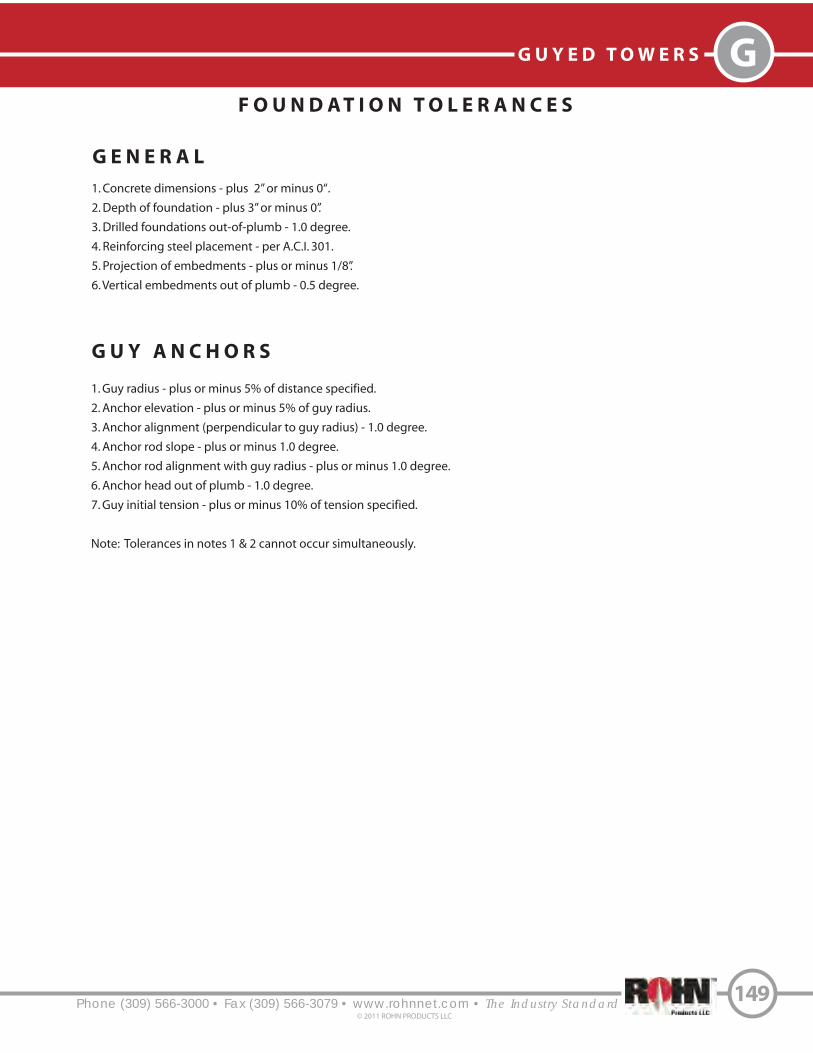
Phone (309) 566-3000 • Fax (309) 566-3079 • www.rohnnet.com • The Industry Standard
GG U Y E D T O W E R S
149© 2011 ROHN PRODUCTS LLC
F O U N D A T I O N T O L E R A N C E S
1. Concrete dimensions - plus 2” or minus 0“.
2. Depth of foundation - plus 3” or minus 0”.
3. Drilled foundations out-of-plumb - 1.0 degree.
4. Reinforcing steel placement - per A.C.I. 301.
5. Projection of embedments - plus or minus 1/8”.
6. Vertical embedments out of plumb - 0.5 degree.
1. Guy radius - plus or minus 5% of distance specified.
2. Anchor elevation - plus or minus 5% of guy radius.
3. Anchor alignment (perpendicular to guy radius) - 1.0 degree.
4. Anchor rod slope - plus or minus 1.0 degree.
5. Anchor rod alignment with guy radius - plus or minus 1.0 degree.
6. Anchor head out of plumb - 1.0 degree.
7. Guy initial tension - plus or minus 10% of tension specified.
Note: Tolerances in notes 1 & 2 cannot occur simultaneously.
G U Y A N C H O R S
G E N E R A L

Phone (309) 566-3000 • Fax (309) 566-3079 • www.rohnnet.com • The Industry Standard
G U Y E D T O W E R S
©2011 ROHN PRODUCTS LLC
G
150
G U Y A R R A N G E M E N T D E T A I L S
1 Guy Attachment 2 Guy Attachment 3 Guy Attachment
4 Guy Attachment 5 Guy Attachment
Turnbuckle (TYP)
Anchor Rod (TYP)
Wire Size Anchor Rod ThimbleTurnbuckle
3/16 EHS
1/4EHS
5/16EHS
3/8EHS
GAC3455TOP
GAC5655TOP
GAC3455TOP
GAC5655TOP
GAC5755TOP
GAC3455TOP
GAC5655TOP
GAC5755TOP
GAC3455TOP
GAC5655TOP
GAC5755TOP
1/2TBE&J
5/8TBE&J
1/2TBE&J
5/8TBE&J
3/4TBE&J
5/8TBE&J
5/8TBE&J
3/4TBE&J
5/8TBE&J
5/8TBE&J
3/4TBE&J
5/16THH
5/16THH
3/8THH
3/8THH
3/8THH
7/16THH
7/16THH
7/16THH
1/2THH
1/2THH
1/2THH
Big Grip w/ End Sleeve
BG2142
BG2144
BG2146
BG2174

G U Y A N C H O R C O N N E C T I O N D E T A I L S
End Sleeve
Turnbuckle (TYP)
Equalizer Plate
Anchor Rod
Thimble (TYP)
Big Grip Preform (TYP)
Cable Clamps
Turnbuckle Safety Cables
1/4” EHS Wire (up to 1” turnbuckles)
5/16” EHS Wire (1 1/4” turnbuckles & larger)
Anchor Connection
Phone (309) 566-3000 • Fax (309) 566-3079 • www.rohnnet.com • The Industry Standard
GG U Y E D T O W E R S
151© 2011 ROHN PRODUCTS LLC

Phone (309) 566-3000 • Fax (309) 566-3079 • www.rohnnet.com • The Industry Standard
G U Y E D T O W E R S
©2011 ROHN PRODUCTS LLC
G
152
G U Y M A S T C O N N E C T I O N D E T A I L S
Tower Brace (REF)Tower Leg (REF)
Guy bracket must rest onhorizontal tower brace andlugs when providedfor larger guys. Big Grip Preform
Thimble
Guy Link
Guy Bracket Connection25G, 45G, 45GSR, 55G
Guy Lug Connection45GSR
Tower Brace (REF)Tower Leg (REF)
Guy Lug
Shackle
Thimble
Big Grip Preform
Guy Tension Bar
Bolt-On Guy Bracket Connection65G
Tower Brace (REF)
Tower Leg (REF)
Big Grip Preform
Thimble
Bolt-OnGuy Bracket

Phone (309) 566-3000 • Fax (309) 566-3079 • www.rohnnet.com • The Industry Standard
GG U Y E D T O W E R S
153© 2011 ROHN PRODUCTS LLC
P A L N U T I N S T A L L A T I O N
When pal nuts are provided, they are to be installed after nuts are tight and with edge lip out as shown. Pal nuts are not
required when self-locking nuts or lock washers are provided.
Flange Plates
Pal Nut
Bolt
Nut
Tower Leg

Phone (309) 566-3000 • Fax (309) 566-3079 • www.rohnnet.com • The Industry Standard
G G U Y E D T O W E R S - 8 0
© 2011 ROHN PRODUCTS LLC
S T A N D A R D 8 0 S E R I E S G U Y E D T O W E R
154
GENERAL USE
The ROHN Model 80 Guyed Tower is designed
with variable sized legs and braces to allow
construction to heights of 1000’. This tower uses
solid or tubular legs with angle or tubular braces
to support microwave, cellular, PCS, AM/FM or
TV applications. The tower is designed on an
equilateral triangle of 41” center-to-center of
each leg. The variable leg and brace sizes allow
!exibility in design so a tower can be created
speci#cally for your unique requirements.
FEATURES
• Solid or Tubular Legs
• Angle or Tubular Braces
• Completely hot-dip galvanized after fabrication
• Easily reinforced for additional loading capability
• Multiple section lengths available
• Guy lug and torque arm sections available
80SERIES
Per Rev G requirements, any structure greater than 10’ requires a climber safety device. Please contact ROHN for ordering information.

S T A N D A R D 8 0 G U Y E D T O W E R
S E C T I O N S
Tower Axis
PLAN VIEW
Phone (309) 566-3000 • Fax (309) 566-3079 • www.rohnnet.com • The Industry Standard
G U Y E D T O W E R S - 8 0
© 2011 ROHN PRODUCTS LLC
G
155
SINGLE BRACED DOUBLE BRACED
35 1/2”
23 11/16”
41”
Tubular or Solid
Round Legs
Tubular or AngleBracing
20’ STANDARD SECTION
80 Sections have several custom designs available depending on your particular
specifications. Sections are available witha variety of different wall thicknesses,
bracing patterns and lengths.
Tubular or Solid Round Leg
Angle Braces
5’ TAPERED BASE
Pier Pin
Bearing Plate

S T A N D A R D 9 0 S E R I E S G U Y E D T O W E R
Phone (309) 566-3000 • Fax (309) 566-3079 • www.rohnnet.com • The Industry Standard
G G U Y E D T O W E R S - 9 0
156© 2011 ROHN PRODUCTS LLC
GENERAL USE
The ROHN Model 90 Guyed tower is designed
speci!cally for microwave installations, cellular,
PCS, other heavy duty communication, TV and
FM broadcast and meteorological equipment
installations. This series has a rating for installations
up to 1500’, using variable size and weight of
tubular or solid steel components. The tower is
designed on an equilateral triangle of 60 1/2”
center-to-center of each leg. The “X” brace
design of the 90 series maximizes strength in
critical areas as well as allows for future upgrading
of the tower for additional loads.
FEATURES
• Solid or Tubular Legs
• Angle Braces
• Completely hot-dip galvanized after fabrication
• Easily reinforced for additional loading capability
• Multiple section lengths available
• Guy lug and torque arm sections available
90SERIES
Per Rev G requirements, any structure greater than 10’ requires a climber safety device. Please contact ROHN for ordering information.
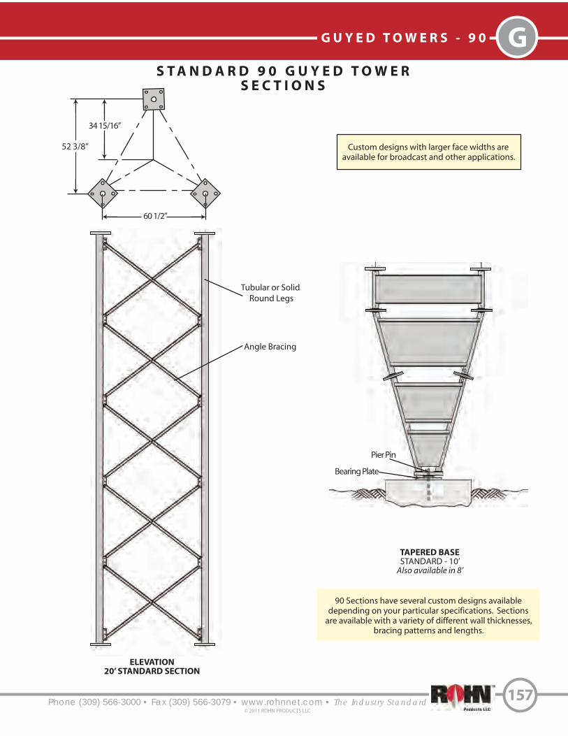
ELEVATION
20’ STANDARD SECTION
S T A N D A R D 9 0 G U Y E D T O W E R
S E C T I O N S
60 1/2”
Phone (309) 566-3000 • Fax (309) 566-3079 • www.rohnnet.com • The Industry Standard
G U Y E D T O W E R S - 9 0
© 2011 ROHN PRODUCTS LLC
G
157
TAPERED BASE
STANDARD - 10’Also available in 8’
90 Sections have several custom designs availabledepending on your particular specifications. Sections
are available with a variety of different wall thicknesses,bracing patterns and lengths.
Pier Pin
Bearing Plate
52 3/8”
34 15/16”
Angle Bracing
Tubular or Solid
Round Legs
Custom designs with larger face widths areavailable for broadcast and other applications.

Phone (309) 566-3000 • Fax (309) 566-3079 • www.rohnnet.com • The Industry Standard© 2011 ROHN PRODUCTS LLC
N O T E S
158


B B R A C K E T E D T O W E R S
S T A N D A R D G - S E R I E S B R A C K E T E D
Phone (309) 566-3000 • Fax (309) 566-3079 • www.rohnnet.com • The Industry Standard© 2011 ROHN PRODUCTS LLC
160
UNIVERSAL HOUSE BRACKET
HBUTVRO
Adjustable to position tower 18” - 36” from wall.
O P T I O N A L A C C E S S O R Y
Typical installation on short base with (2)HBUTVRO brackets.
(Refer to G-Series accessories for short base)
* Per Rev. G requriements, any structure greater than 10’ requires a climber safety device. Please see page 209 for ordering information.
GENERAL USE
ROHN G-Series Bracketed towers can be installed
adjacent to buildings using brackets to secure
the tower along the height of the structure.
FEATURES
• Completely hot-dip galvanized after fabrication
• Cross bracing is formed by a continuous solid
rod bracing fashioned into a Zig-Zag pattern
for strength
• Pre-engineered loading charts to meet varying
individual specs and site conditions
• Typical uses include: small dishes, broadband,
security and two-way communication.
G-SERIES(BRACKETED)

2 5 G B R A C K E T E D
A L L O W A B L E A N T E N N A A R E A S
B R A C K E T E D T O W E R S - 2 5 G B
Phone (309) 566-3000 • Fax (309) 566-3079 • www.rohnnet.com • The Industry Standard© 2011 ROHN PRODUCTS LLC
161
Tower Height(FT.)
40
50
60
70
80
90
100
Upper (FT.)
30.0
36.0
46.0
56.0
66.0
66.0
66.0
Lower (FT.)
15.0
18.0
23.0
28.0
33.0
33.0
33.0
Bracket Elevations Allowable Antenna Areas (SQ. FT.)
70 [85] MPH
15.3
14.6
14.0
13.5
13.1
6.8
1.7
80 [95] MPH
11.3
10.0
8.9
8.3
7.7
4.9
-
90 [105] MPH
7.7
6.8
5.9
5.5
5.0
-
-
1. Tower designs are in accordance with ANSI/EIA-222-F. Wind speeds indicated as fastest mile [3-second gust].
2. All towers must have “fixed bases” with both bracket elevations. Pinned bases must not be used.
3. Designs assume one 5/8” transmission line on each face (total=3), symmetrically placed.
4. Antennas and mounts assumed symmetrically placed at tower apex.
5. Allowable antenna areas assume all round antenna members.
6. Allowable flat-plate antenna areas, based on EIA RS-222-C, may be obtained by multiplying areas shown by 0.6.
7. All brackets are to be ROHN (P/N HBUTVRO).
8. The interface of tower brackets to supporting structure is to be designed by others and must support a minimum horizontal force of 815 lbs.
9. Foundation designs are in accordance with ANSI/TIA/EIA-222-F, “Structural Standards for Steel Antenna Towers and Antenna Supporting
Structures”, Section 7, for “Normal” soil conditions. “Normal” soil is defined as dry, cohesive soil with an allowable net vertical bearing
capacity of 4000 PSF and an allowable net horizontal pressure of 400 PSF per linear foot of depth to a maximum of 4000 PSF.
Refer to pages 147-153 for General Installation and Foundation Notes.
F O U N D A T I O N I N F O R M A T I O N
SB25G5 Base Sectionor Tower Base Section
6” Projection
6”2” Min.
Compacted Sand & Gravel Drainage Bed
2’ - 6” Roundor Square
Tower Axis andCenter of Pier
VOLUME OF CONCRETE
Square Pier 1.0 cu. yds.Round Pier 0.8 cu. yds.
==
4’ - 0”
#3 Circular Tiesat 3” Max O.C.W/ 18” Laps
(8) #7 VerticalBars Equally
Spaced
25G
Grade
6” Min.
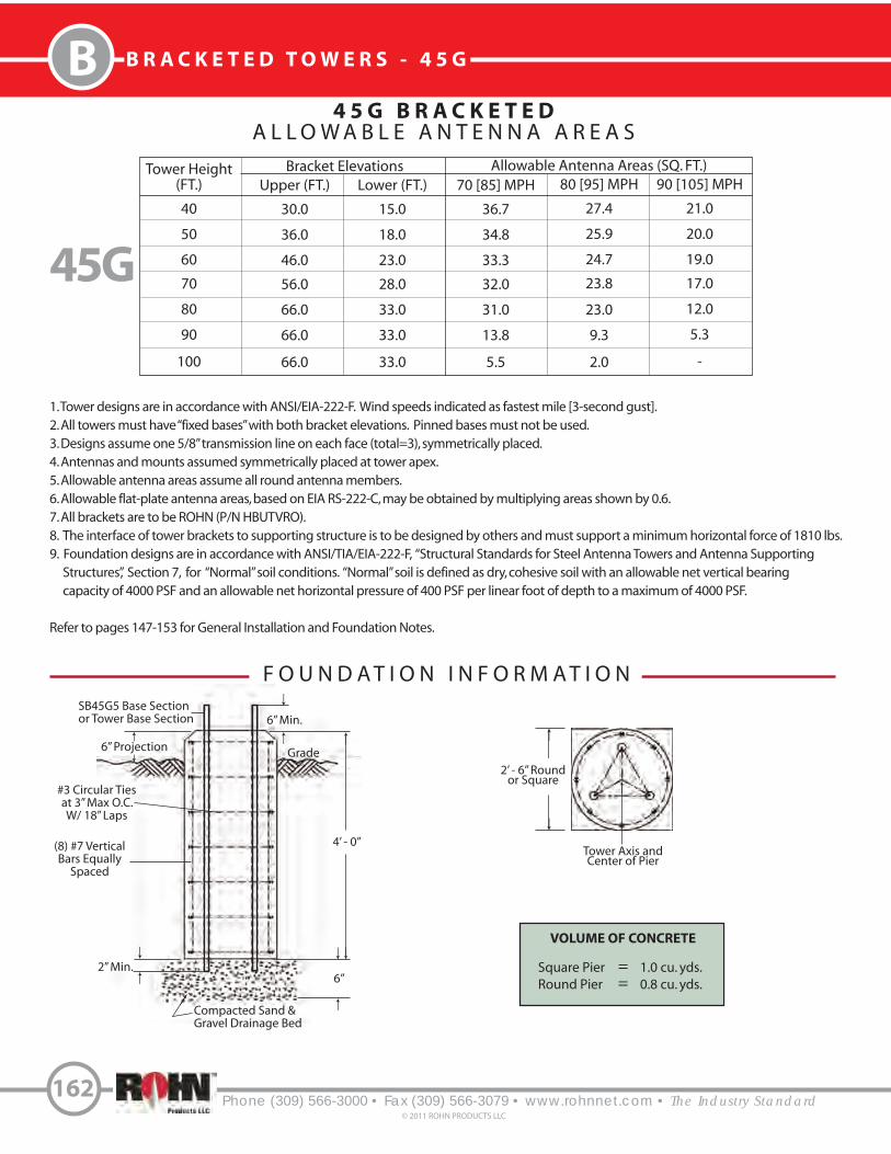
4 5 G B R A C K E T E D
A L L O W A B L E A N T E N N A A R E A S
Tower Height(FT.)
40
50
60
70
80
90
100
Upper (FT.)
30.0
36.0
46.0
56.0
66.0
66.0
66.0
Lower (FT.)
15.0
18.0
23.0
28.0
33.0
33.0
33.0
Bracket Elevations Allowable Antenna Areas (SQ. FT.)
70 [85] MPH
36.7
34.8
33.3
32.0
31.0
13.8
5.5
80 [95] MPH
27.4
25.9
24.7
23.8
23.0
9.3
2.0
90 [105] MPH
21.0
20.0
19.0
17.0
12.0
5.3
-
B B R A C K E T E D T O W E R S - 4 5 G
Phone (309) 566-3000 • Fax (309) 566-3079 • www.rohnnet.com • The Industry Standard© 2011 ROHN PRODUCTS LLC
162
45G
F O U N D A T I O N I N F O R M A T I O N
2’ - 6” Roundor Square
Tower Axis andCenter of Pier
VOLUME OF CONCRETE
Square Pier 1.0 cu. yds.Round Pier 0.8 cu. yds.
==
1. Tower designs are in accordance with ANSI/EIA-222-F. Wind speeds indicated as fastest mile [3-second gust].
2. All towers must have “fixed bases” with both bracket elevations. Pinned bases must not be used.
3. Designs assume one 5/8” transmission line on each face (total=3), symmetrically placed.
4. Antennas and mounts assumed symmetrically placed at tower apex.
5. Allowable antenna areas assume all round antenna members.
6. Allowable flat-plate antenna areas, based on EIA RS-222-C, may be obtained by multiplying areas shown by 0.6.
7. All brackets are to be ROHN (P/N HBUTVRO).
8. The interface of tower brackets to supporting structure is to be designed by others and must support a minimum horizontal force of 1810 lbs.
9. Foundation designs are in accordance with ANSI/TIA/EIA-222-F, “Structural Standards for Steel Antenna Towers and Antenna Supporting
Structures”, Section 7, for “Normal” soil conditions. “Normal” soil is defined as dry, cohesive soil with an allowable net vertical bearing
capacity of 4000 PSF and an allowable net horizontal pressure of 400 PSF per linear foot of depth to a maximum of 4000 PSF.
Refer to pages 147-153 for General Installation and Foundation Notes.
SB45G5 Base Sectionor Tower Base Section
6” Projection
6”2” Min.
Compacted Sand & Gravel Drainage Bed
4’ - 0”
#3 Circular Tiesat 3” Max O.C.W/ 18” Laps
(8) #7 VerticalBars Equally
Spaced
Grade
6” Min.
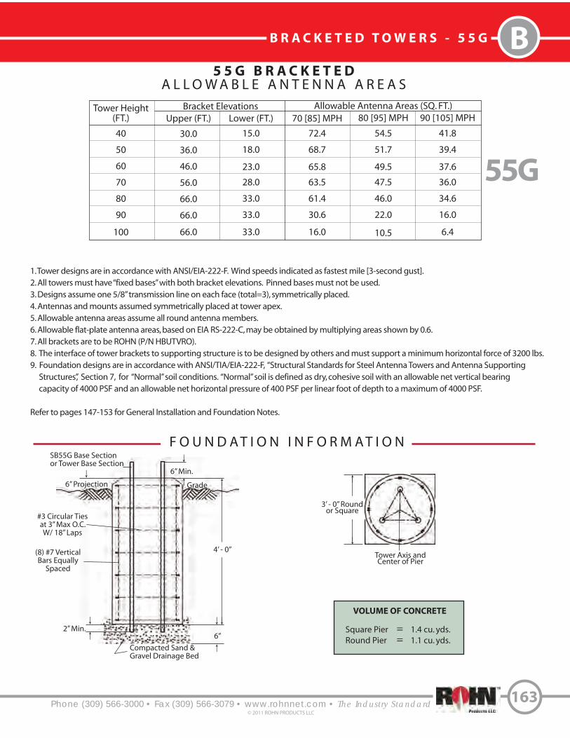
5 5 G B R A C K E T E D
A L L O W A B L E A N T E N N A A R E A S
B R A C K E T E D T O W E R S - 5 5 G B
Phone (309) 566-3000 • Fax (309) 566-3079 • www.rohnnet.com • The Industry Standard© 2011 ROHN PRODUCTS LLC
163
Tower Height(FT.)
40
50
60
70
80
90
100
Upper (FT.)
30.0
36.0
46.0
56.0
66.0
66.0
66.0
Lower (FT.)
15.0
18.0
23.0
28.0
33.0
33.0
33.0
Bracket Elevations Allowable Antenna Areas (SQ. FT.)
70 [85] MPH
72.4
68.7
65.8
63.5
61.4
30.6
16.0
80 [95] MPH
54.5
51.7
49.5
47.5
46.0
22.0
10.5
90 [105] MPH
41.8
39.4
37.6
36.0
34.6
16.0
6.4
55G
F O U N D A T I O N I N F O R M A T I O NSB55G Base Sectionor Tower Base Section
6” Projection
6”2” Min.
Compacted Sand & Gravel Drainage Bed
3’ - 0” Roundor Square
Tower Axis andCenter of Pier
VOLUME OF CONCRETE
Square Pier 1.4 cu. yds.Round Pier 1.1 cu. yds.
==
4’ - 0”
#3 Circular Tiesat 3” Max O.C.W/ 18” Laps
(8) #7 VerticalBars Equally
Spaced
1. Tower designs are in accordance with ANSI/EIA-222-F. Wind speeds indicated as fastest mile [3-second gust].
2. All towers must have “fixed bases” with both bracket elevations. Pinned bases must not be used.
3. Designs assume one 5/8” transmission line on each face (total=3), symmetrically placed.
4. Antennas and mounts assumed symmetrically placed at tower apex.
5. Allowable antenna areas assume all round antenna members.
6. Allowable flat-plate antenna areas, based on EIA RS-222-C, may be obtained by multiplying areas shown by 0.6.
7. All brackets are to be ROHN (P/N HBUTVRO).
8. The interface of tower brackets to supporting structure is to be designed by others and must support a minimum horizontal force of 3200 lbs.
9. Foundation designs are in accordance with ANSI/TIA/EIA-222-F, “Structural Standards for Steel Antenna Towers and Antenna Supporting
Structures”, Section 7, for “Normal” soil conditions. “Normal” soil is defined as dry, cohesive soil with an allowable net vertical bearing
capacity of 4000 PSF and an allowable net horizontal pressure of 400 PSF per linear foot of depth to a maximum of 4000 PSF.
Refer to pages 147-153 for General Installation and Foundation Notes.
Grade
6” Min.

Phone (309) 566-3000 • Fax (309) 566-3079 • www.rohnnet.com • The Industry Standard© 2011 ROHN PRODUCTS LLC
164
N O T E S


Phone (309) 566-3000 • Fax (309) 566-3079• www.rohnnet.com • The Industry Standard
SS S E L F - S U P P O R T I N G T O W E R S
166© 2011 ROHN PRODUCTS LLC
S T A N D A R D G - S E R I E S S E L F - S U P P O R T I N G
Typical Self-Supporting
25G, 45G and 55G Tower
Typical Self-Supporting
45GSR and 65G Tower
REV. G
includes
REV. F &
Per Rev G requirements, any structure greater than 10’ requires a climber
safety device. Please see page 209 for ordering information.
GENERAL USE
The self-supporting G-Series towers o!er an easy,
low-cost solution to get light weight antennas in
the air quickly. By using the G-Series tower as a
self-supporting structure, you minimize land
area usage. They are functional in a wide variety
of wind speeds. See ROHN’s standard designs
to help identify the right structure for your project.
These are the same sturdy, robust tower sections
that ROHN has fabricated for years. Each larger
model allows for more loading capacity.
FEATURES
• Completely hot-dip galvanized after fabrication
• Cross bracing is formed by a continuous solid
rod bracing fashioned into a zig-zag pattern
for strength
• Pre-engineered loading charts meet varying
individual specs and site conditions
• Typical uses include: small dishes, broadband,
security and two-way communication
• All towers have ‘#xed’ bases
KITS
The kit part numbers for ROHN Self-Supporting
G-Series towers include:
• Short base for embedment in concrete
• Rev F ground kit
• All tower sections and connection hardware
• Tapered top (25G and 45G towers)
• Top plate (55G towers)
• Cap plate kit (65G towers)
G-SERIESSELF-SUPPORTING

Note: Antenna areas, ft. , assume all round antenna members.2
167

Exp. B
82
74
66
59
46
35
27
20
13
Part No.
45SR010
45SR020
45SR030
45SR035
45SR040
45SR045
45SR050
45SR055
45SR060
45GSR
Exp. C
66
55
43
38
30
22
15
9
4
Exp. B
95
95
87
76
60
48
38
29
22
Part No.
45SR010
45SR020
45SR030
45SR035
45SR040
45SR045
45SR050
45SR055
45SR060
EPA
Exp. C
84
71
58
52
40
31
23
16
11
Height
10’
20’
30’
35‘
40’
45‘
50’
55‘
60’
Exp. B
16.5
10.6
3.1
110 MPH 3-Second Gust Wind Speed
Part No.
25SS010
25SS020
25SS030
25G
Exp. C
12.7
7.2
0.4
Exp. B
39.4
18.3
6.5
1.7
Part No.
45SS010
45SS020
45SS030
45SS035
45G
Exp. C
31.9
12.3
1.9
-
Exp. B
63
34
17
11
5
Part No.
55SS010
55SS020
55SS030
55SS035
55SS040
55G
Exp. C
51
25
9
4
-
Exp. B
95
95
65
48
35
25
17
10
4
Part No.
65SS010
65SS020
65SS030
65SS035
65SS040
65SS045
65SS050
65SS055
65SS060
65G
Exp. C
95
81
43
30
21
13
7
-
-
Height
10’
20’
30’
35‘
40’
45‘
50’
55‘
60’
Exp. B
20.7
14.0
5.3
2.1
100 MPH 3-Second Gust Wind Speed
Part No.
25SS010
25SS020
25SS030
25SS035
25G
Exp. C
16.4
9.9
2.2
-
Exp. B
47.4
23.2
9.7
5.1
1.2
Part No.
45SS010
45SS020
45SS030
45SS035
45SS040
45G
Exp. C
39.5
16.9
4.8
0.7
-
Part No.
55SS010
55SS020
55SS030
55SS035
55SS040
55SS045
55G
Exp. C
63
32
14
8
3
-
Exp. B
95
95
81
61
47
35
26
17
11
Part No.
65SS010
65SS020
65SS030
65SS035
65SS040
65SS045
65SS050
65SS055
65SS060
65G
Exp. C
95
95
55
40
29
20
13
6
1
G S E R I E SR E V . G E F F E C T I V E P R O J E C T E D A R E A ( S Q . F T . )
NO
ICE
90
MP
H1
00
MP
H1
10
MP
H
Height
10’
20’
30’
35‘
40’
45‘
50’
55‘
60’
Exp. B
26.8
18.5
7.9
4.4
1.3
90 MPH 3-Second Gust Wind Speed
Part No.
25SS010
25SS020
25SS030
25SS035
25SS040
EPA
Exp. C
21.3
13.4
4.1
1.2
-
Exp. B
60.0
31.3
16.1
9.8
4.9
0.7
Part No.
45SS010
45SS020
45SS030
45SS035
45SS040
45SS045
EPA
Exp. C
47.5
22.7
8.4
3.8
-
-
Part No.
55SS010
55SS020
55SS030
55SS035
55SS040
55SS045
55SS050
EPA
Exp. C
79
42
21
14
8
3
-
Exp. B
95
95
95
80
62
48
37
28
20
Part No.
65SS010
65SS020
65SS030
65SS035
65SS040
65SS045
65SS050
65SS055
65SS060
EPA
Exp. C
95
95
71
54
41
30
21
14
7
3-S
eco
nd
Gu
st3
-Se
con
d G
ust
3-S
eco
nd
Gu
st
Exp. B
67
59
51
45
35
26
19
13
7
Part No.
45SR010
45SR020
45SR030
45SR035
45SR040
45SR045
45SR050
45SR055
45SR060
45GSR
Exp. C
53
43
32
27
22
15
9
4
-
Exp. B
78
43
24
17
10
5
Exp. B
80
56
34
25
17
11
5
45GSR25G 45G 55G 65G
EPAEPA EPA EPA EPA
EPAEPA EPA EPA EPA
Phone (309) 566-3000 • Fax (309) 566-3079 • www.rohnnet.com • The Industry Standard
SS S E L F - S U P P O R T I N G T O W E R S
168© 2011 ROHN PRODUCTS LLC
Note: Antenna areas, ft. , assume all round antenna members.2

S E L F - S U P P O R T I N G T O W E R S
Phone (309) 566-3000 • Fax (309) 566-3079 • www.rohnnet.com • The Industry Standard© 2011 ROHN PRODUCTS LLC
169
SS
W(Square)
Tower Axis & Center of Pad
CL
CL
PLAN VIEW
Tower Section orShort Base Section
#7 Bars 12”on CenterEach Way
6”
6”
4’
2” min. projection requiredfor proper drainage
Compacted Sand & GravelDrainage Bed - not requiredfor 45GSR
Grade
25G
45G
55G
45GSR65G
4’ - 0”
5’ - 3”
6’ - 0”
7’ - 9”
2.4
4.1
5.3
8.9
Tower
Mat
Width
(W)
ConcreteVolume
(Cu. Yds.)
CONCRETE BASE PLATEWITH ANCHORS
25GSSBFOR USE WITH SELF-SUPPORTING
25G TOWERS.
ALTERNATIVE TO USING SHORT BASE.BASE BOLTS & TEMPLATE MUSTBE ORDERED SEPARATELY.
S E L F - S U P P O R T I N G G - S E R I E S F O U N D A T I O N S
Grade 6”
4’
Grade6”
#7 Bars 12”on CenterEach Way,
Top & Bottom
ELEVATION VIEW25G (shown), 45G & 55G
SELF-SUPPORTING TOWER FOUNDATION
ELEVATION VIEW45GSR
SELF-SUPPORTING TOWER FOUNDATION
ELEVATION VIEW65G
SELF-SUPPORTING TOWER FOUNDATION
BASE BOLTS & TEMPLATEKH8175A
FOR USE WITH 25GSSBIN SELF-SUPPORTING 25G TOWERAPPLICATIONS. KIT INCLUDES (1)TEMPLATE & (4) BASE BOLTS.
2” min. projection above the !nished
concrete
6” min. projection above the !nished
concrete
4’
0” to 3”
2” Min.

Phone (309) 566-3000 • Fax (309) 566-3079 • www.rohnnet.com • The Industry Standard
SS S E L F - S U P P O R T I N G T O W E R S
170
© 2011 ROHN PRODUCTS LLC
SELF-SUPPORTING G-SERIES DESIGN NOTES
1. Tower designs are in accordance with approved national standard ANSI/EIA-222-F and ANSI/TIA-222G,
Structure Class I, Exposures B and C, Topographic Category I.
2. All towers must have “fixed” bases. Pinned bases may not be used.
3. Designs assume transmission lines symmetrically placed as follows:
25G Tower - One 5/8” Line on each face (Total =3)
45G Tower - One 7/8” Line and one 1/2“ line on each face (Total = 3 @ 7/8” & 3 @ 1/2”)
55G & 65G Towers - Two 7/8” Lines on each face (Total =6)
4. Antennas and mounts assumed symmetrically placed at tower apex.
5. Rev F tabulated allowable antenna areas assume all round antenna members.
6. Allowable flat-plate antenna areas, based on EIA RS-222-C, may be obtained by multiplying Rev. F Antenna areas
shown by 0.6.
7. Standard foundation designs are based on Rev. F normal soil and Rev. G presumptive clay soil parameters.
Refer to pages 147-153 for General Installation and Foundation Notes.

Phone (309) 566-3000 • Fax (309) 566-3079 • www.rohnnet.com • The Industry Standard171
© 2011 ROHN PRODUCTS LLC
N O T E S
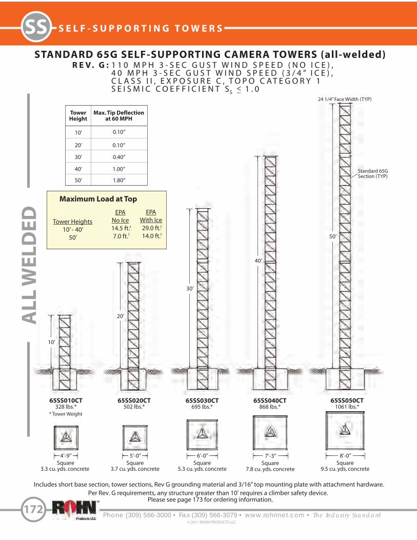
1 1 0 M P H 3 - S E C G U S T W I N D S P E E D ( N O I C E ) ,4 0 M P H 3 - S E C G U S T W I N D S P E E D ( 3 / 4 ” I C E ) ,C L A S S I I , E X P O S U R E C , T O P O C A T E G O R Y 1S E I S M I C C O E F F I C I E N T S 1 . 0
Phone (309) 566-3000 • Fax (309) 566-3079 • www.rohnnet.com • The Industry Standard
SS S E L F - S U P P O R T I N G T O W E R S
172© 2011 ROHN PRODUCTS LLC
STANDARD 65G SELF-SUPPORTING CAMERA TOWERS (all-welded)
5’-0”Square
3.7 cu. yds. concrete
6’-0”Square
5.3 cu. yds. concrete
7’-3”Square
7.8 cu. yds. concrete
8’-0”Square
9.5 cu. yds. concrete
10’
20’
30’
40’
50’
65SS010CT328 lbs.*
65SS020CT502 lbs.*
65SS030CT695 lbs.*
65SS040CT868 lbs.*
65SS050CT1061 lbs.*
TowerHeight
10’
20’
30’
40’
50’
Max. Tip Deflectionat 60 MPH
0.10”
0.10“
0.40”
1.00“
1.80”
Maximum Load at Top
EPANo Ice14.5 ft.7.0 ft.
EPAWith Ice29.0 ft.14.0 ft.
2
4’-9”Square
3.3 cu. yds. concrete
Includes short base section, tower sections, Rev G grounding material and 3/16” top mounting plate with attachment hardware.
Tower Heights10’ - 40’
50’
24 1/4” Face Width (TYP)
R E V . G :
2
2
2
AL
L W
EL
DE
D
S<_
Per Rev. G requirements, any structure greater than 10’ requires a climber safety device. Please see page 173 for ordering information.
Standard 65GSection (TYP)
* Tower Weight

S E L F - S U P P O R T I N G T O W E R S
Phone (309) 566-3000 • Fax (309) 566-3079 • www.rohnnet.com • The Industry Standard© 2011 ROHN PRODUCTS LLC
173
SS
6 5 G C A M E R A T O W E R S
S TA N D A R D F O U N D AT I O N D E TA I L S
1. Tower designs are in accordance with ANSI/TIA/222-G.2. Camera and mount assumed symmetrically placed at tower top.3. Tower design assumes one 7/8” line on each tower face.4. Assembly drawings and standard foundation details are provided with the tower.5. Standard foundation illustrated is for general information only and is based on Rev G presumptive clay soil parameters.
Tower Axis
1’ - 2”1’ - 9”
CL
CL
2’-1/4”
“W”Square
W/2
W/2
6” of Compacted Sand& Gravel for Drainage
3’ - 6”
2” Min.
#7 Horizontal Bars12” O.C. Each Way(Top & Bottom)
6”
G E N E R A L N O T E S
CLIMBING HARNESS
TTFBH-4DJOURNEYMAN HARNESS
TTFBH-C/PPROFESSIONAL HARNESS
SAFETY CABLESLIDER WITH CARABINEER
TT-WG-500-W/SMCANTI-CLIMB PANELS
VW915AORDERED SEPARATELY
A CC E S S O R I E S
Grade
See tower elevation page for “W” dimension.
SAFETY CABLE SYSTEM
TT05065FITS ALL TOWER HEIGHTS
2” Min.

R E V . G :
S<_
1 1 0 M P H 3 - S E C G U S T W I N D S P E E D ( N O I C E ) ,4 0 M P H 3 - S E C G U S T W I N D S P E E D ( 3 / 4 ” I C E ) ,C L A S S I I , E X P O S U R E C , T O P O C A T E G O R Y 1S E I S M I C C O E F F I C I E N T S 1 . 0
Phone (309) 566-3000 • Fax (309) 566-3079 • www.rohnnet.com • The Industry Standard
SS S E L F - S U P P O R T I N G T O W E R S
174© 2011 ROHN PRODUCTS LLC
STANDARD VG SELF-SUPPORTING CAMERA TOWERS (field bolted)
5’-6”Square
4.5 cu. yds. concrete
6’-0”Square
5.3 cu. yds. concrete
7’-3”Square
7.8 cu. yds. concrete
8’-0”Square
9.5 cu. yds. concrete
10’
20’
30’
40’
50’
VG010CT500 lbs.*
VG020CT735 lbs.*
VG030CT1016 lbs.*
VG040CT1251 lbs.*
VG050CT1531 lbs.*
TowerHeight
10’
20’
30’
40’
50’
Max. Tip Deflectionat 60 MPH
0.10”
0.10“
0.20”
0.70“
1.30”
Maximum Load at Top
EPA
No Ice14.5 ft.7.0 ft.
EPAWith Ice29.0 ft.14.0 ft.
2
5’-0”Square
3.7 cu. yds. concrete
Includes anchor bolts, templates, tower sections, Rev G grounding material, 1/2” top mounting plate with attachment hardware and step bolts.
Tower Heights10’ - 40’
50’
30” Face Width (TYP)
2
2
2
KN
OC
KE
D D
OW
N
Per Rev. G requriements, any structure greater than 10’ requires a climber safety device. See page 175 for ordering information.
2 3/8” O.D.Tubular Legs(TYP)
1 1/2” x 1/8”Angle Bracing(TYP)
* Tower Weight

S E L F - S U P P O R T I N G T O W E R S
Phone (309) 566-3000 • Fax (309) 566-3079 • www.rohnnet.com • The Industry Standard© 2011 ROHN PRODUCTS LLC
175
SS
V G C A M E R A T O W E R S
S TA N D A R D F O U N D AT I O N D E TA I L S
1. Tower designs are in accordance with ANSI/TIA/222-G.2. Camera and mount assumed symmetrically placed at tower top. 3. Tower design assumes one 7/8” line on each tower face.4. Assembly drawings and standard foundation details are provided with the tower.5. Standard foundation illustrated is for general information only and is based on Rev G presumptive clay soil parameters.
Refer to pages 147-153 for Foundation General Notes.
Tower Axis
CL
CL
2’- 6”
“W”Square
W/2
W/2
3’ - 6”
#7 Horizontal Bars12” O.C. Each Way(Top & Bottom)
6”
G E N E R A L N O T E S
A C C E S S O R I E S
Anchor BoltsSee Anchor Bolt layout provided withtower prior to placing concrete.
Grade
See tower elevation page for “W” dimensions.
CLIMBING HARNESS
TTFBH-4DJOURNEYMAN HARNESS
TTFBH-C/PPROFESSIONAL HARNESS
SAFETY CABLESLIDER WITH CARABINEER
TT-WG-500-W/SMCANTI-CLIMB PANELS
VW917AORDERED SEPARATELY
14”21”
SAFETY CABLE SYSTEM
TT050SSLFITS ALL TOWER HEIGHTS

Phone (309) 566-3000 • Fax (309) 566-3079 • www.rohnnet.com • The Industry Standard
SS S E L F - S U P P O R T I N G T O W E R S - R S L
176© 2011 ROHN PRODUCTS LLC
18”
21”
25”
28”
32”
35”
38”
42”
45”
49”
52”
Top Mount
GENERAL USE
The ROHN RSL is a light weight self-supporting
tower designed for use in broadband, public
safety and security applications. The RSL reaches
above line-of-site obstacles such as tree tops,
hilly terrain and buildings. If your site is remote
or rugged, the RSL is shipped knocked down to
reduce shipping cost and time.
RSL
FEATURES
• Available in heights from 20’ up to 100’
• High strength 60 formed angle legs
• Aerodynamic tubular bracing
• Easy to transport and assemble
• Ships in 10’ sections or knocked-down
• Tower material is hot-dip galvanized
• Assembly drawings provided with tower
Optional items are available and may be ordered
separately:
• Step bolts
• Safety climbing device
• Top post
• Anti-climb panels
• Side arm mount
• Dish mount
• Grounding kit
Refer to page 185 for foundation details.
o
Per Rev G requirements, any structure greater than 10’ requires a climber
safety device. Please see page 184 for ordering information.
Nominalface width
R110’
R510’
R610’
R410’
R710’
R210’
R810’
R310’
R910’
R1010’
STANDARD RSL SELF-SUPPORTING TOWERS (field bolted)

S E L F - S U P P O R T I N G T O W E R S - R S L
Phone (309) 566-3000 • Fax (309) 566-3079 • www.rohnnet.com • The Industry Standard© 2011 ROHN PRODUCTS LLC
177
SS
18”
28”
R030L103
E.P.A. (ft. )
70
61534130
RSB03
RAL03
Wt. 437 lbs.
Kit No.:Fastest Mile[3-sec Gust]
70 [85]
75 [90]
80 [95]
90 [105]
100 [115]
Short Base
Anchor Base
2
Base Options
Face spread attop of tower
Face spread atbase of tower
Tower weight
Wind speed and allowable EPA for each
The RSL short base or anchor bolt andtemplate base must be ordered separately
R 030 L 1 03
TowerModel
TowerHeight
Load Scheme:Light
MediumHeavy
Tower topsection
Tower basesection
B U Y E R S G U I D E
DESIGN NOTES:
1. Tower designs conform to ANSI/TIA/EIA-222-F for the basic wind speeds indicated without ice. Tower designs also conform to the
ANSI/TIA/EIA-222-F Standard for 1/2 inch radial ice load occuring simultaneously with 75% of the no ice design wind pressures.
2. Antennas and mounts are assumed to be symmetrically mounted at or below the top of the tower for determining overall reactions and
member forces. Design assumes the weight of antennas and mounts does not exceed 300 lbs.
3. Design assumes maximum top mast load is limited to 5 sq. ft. EPA and 100 lbs. vertical load. All other loading is assumed to be mounted
below the top mast.
4. Tower designs assume a 1/2 inch transmission line for each 10 square feet of EPA up to a maximum of three lines, one line per tower face.
5. Foundation designs are in accordance with ANSI/TIA/EIA-222-F, “Structural Standards for Steel Antenna Towers and Antenna Supporting
Structures”, Section 7, for “Normal” soil conditions. “Normal” soil is defined as dry, cohesive soil with an allowable net vertical bearing
capacity of 4000 PSF and an allowable net horizontal pressure of 400 PSF per linear foot of depth to a maximum of 4000 PSF.
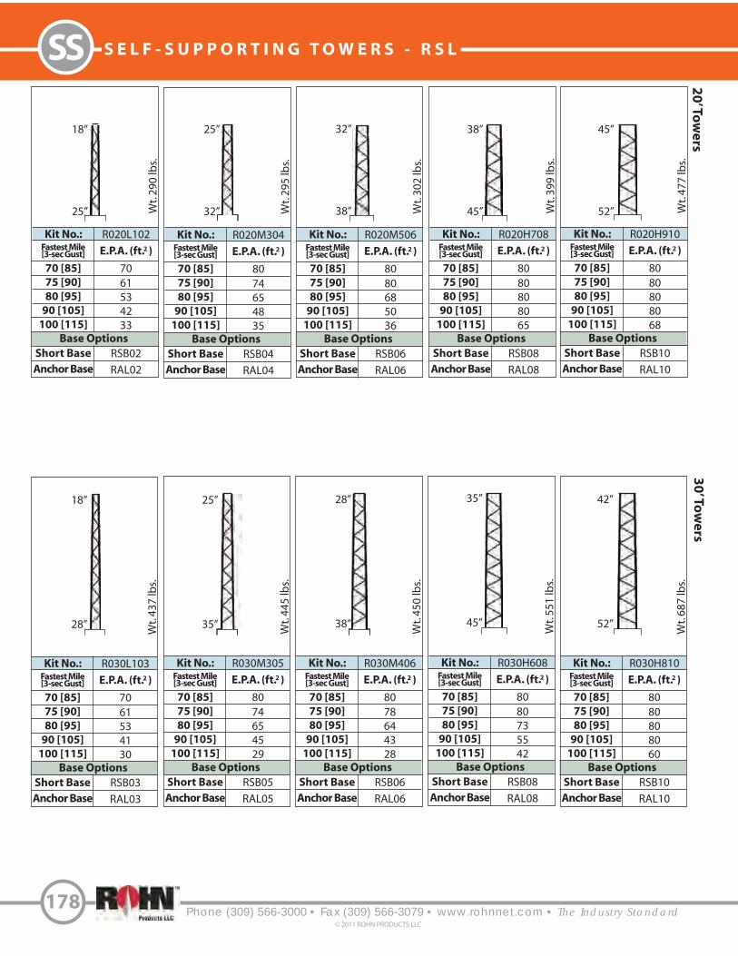
Phone (309) 566-3000 • Fax (309) 566-3079 • www.rohnnet.com • The Industry Standard
SS S E L F - S U P P O R T I N G T O W E R S - R S L
178© 2011 ROHN PRODUCTS LLC
20
’ Tow
ers
30
’ Tow
ers
18”
25”
25”
32”
32”
38”
38”
45”
45”
52”
18”
28”
25”
35”
28”
38”
35”
45”
42”
52”
R020L102
E.P.A. (ft. )
70
61
53
42
33
RSB02
RAL02
Wt. 290 lbs.
Kit No.:Fastest Mile[3-sec Gust]
70 [85]
75 [90]
80 [95]
90 [105]
100 [115]
Short Base
Anchor Base
2
Base Options
R020M304
E.P.A. (ft. )
80
74
65
48
35
RSB04
RAL04
Wt. 295 lbs.
Kit No.:Fastest Mile[3-sec Gust]
70 [85]
75 [90]
80 [95]
90 [105]
100 [115]
Short Base
Anchor Base
2
Base Options
R020M506
E.P.A. (ft. )
80
80
68
50
36
RSB06
RAL06
Wt. 302 lbs.
Kit No.:Fastest Mile[3-sec Gust]
70 [85]
75 [90]
80 [95]
90 [105]
100 [115]
Short Base
Anchor Base
2
Base Options
R020H708
E.P.A. (ft. )
80
80
80
80
65
RSB08
RAL08
Wt. 399 lbs.
Kit No.:Fastest Mile[3-sec Gust]
70 [85]
75 [90]
80 [95]
90 [105]
100 [115]
Short Base
Anchor Base
2
Base Options
R020H910
E.P.A. (ft. )
80
80
80
80
68
RSB10
RAL10
Wt. 477 lbs.
Kit No.:Fastest Mile[3-sec Gust]
70 [85]
75 [90]
80 [95]
90 [105]
100 [115]
Short Base
Anchor Base
2
Base Options
R030L103
E.P.A. (ft. )
70
61
53
41
30
RSB03
RAL03
Wt. 437 lbs.
Kit No.:Fastest Mile[3-sec Gust]
70 [85]
75 [90]
80 [95]
90 [105]
100 [115]
Short Base
Anchor Base
2
Base Options
R030M305
E.P.A. (ft. )
80
74
65
45
29
RSB05
RAL05
Wt. 445 lbs.
Kit No.:Fastest Mile[3-sec Gust]
70 [85]
75 [90]
80 [95]
90 [105]
100 [115]
Short Base
Anchor Base
2
Base Options
R030M406
E.P.A. (ft. )
80
78
64
43
28
RSB06
RAL06
Wt. 450 lbs.
Kit No.:Fastest Mile[3-sec Gust]
70 [85]
75 [90]
80 [95]
90 [105]
100 [115]
Short Base
Anchor Base
2
Base Options
R030H608
E.P.A. (ft. )
80
80
73
55
42
RSB08
RAL08
Wt. 551 lbs.
Kit No.:Fastest Mile[3-sec Gust]
70 [85]
75 [90]
80 [95]
90 [105]
100 [115]
Short Base
Anchor Base
2
Base Options
R030H810
E.P.A. (ft. )
80
80
80
80
60
RSB10
RAL10
Wt. 687 lbs.
Kit No.:Fastest Mile[3-sec Gust]
70 [85]
75 [90]
80 [95]
90 [105]
100 [115]
Short Base
Anchor Base
2
Base Options

S E L F - S U P P O R T I N G T O W E R S - R S L
Phone (309) 566-3000 • Fax (309) 566-3079 • www.rohnnet.com • The Industry Standard© 2011 ROHN PRODUCTS LLC
179
SS4
0’ T
ow
ers
18”
32”
21”
35”
28”
42”
35”
49”
38”
52”
18”
35”
21”
38”
25”
42”
32”
49”
35”
52”
50
’ To
we
rs
R040L104
E.P.A. (ft. )
54
44
36
24
15
RSB04
RAL04
Wt. 585 lbs.
Kit No.:Fastest Mile[3-sec Gust]
70 [85]
75 [90]
80 [95]
90 [105]
100 [115]
Short Base
Anchor Base
2
Base Options
R040M205
E.P.A. (ft. )
63
52
43
29
19
RSB05
RAL05
Wt. 590 lbs.
Kit No.:Fastest Mile[3-sec Gust]
70 [85]
75 [90]
80 [95]
90 [105]
100 [115]
Short Base
Anchor Base
2
Base Options
R040M407
E.P.A. (ft. )
80
75
62
40
25
RSB07
RAL07Wt. 639 lbs.
Kit No.:Fastest Mile[3-sec Gust]
70 [85]
75 [90]
80 [95]
90 [105]
100 [115]
Short Base
Anchor Base
2
Base Options
R040H609
E.P.A. (ft. )
80
80
69
52
40
RSB09
RAL09
Wt. 788 lbs.
Kit No.:Fastest Mile[3-sec Gust]
70 [85]
75 [90]
80 [95]
90 [105]
100 [115]
Short Base
Anchor Base
2
Base Options
R040H710
E.P.A. (ft. )
80
80
80
75
49
RSB10
RAL10
Wt. 876 lbs.
Kit No.:Fastest Mile[3-sec Gust]
70 [85]
75 [90]
80 [95]
90 [105]
100 [115]
Short Base
Anchor Base
2
Base Options
R050L105
E.P.A. (ft. )
37
29
22
11
4
RSB05
RAL05
Wt. 735 lbs.
Kit No.:Fastest Mile[3-sec Gust]
70 [85]
75 [90]
80 [95]
90 [105]
100 [115]
Short Base
Anchor Base
2
Base Options
R050M206
E.P.A. (ft. )
43
34
26
15
6
RSB06
RAL06
Wt. 742 lbs.
Kit No.:Fastest Mile[3-sec Gust]
70 [85]
75 [90]
80 [95]
90 [105]
100 [115]
Short Base
Anchor Base
2
Base Options
R050M307
E.P.A. (ft. )
67
54
44
30
16
RSB07
RAL07
Wt. 786 lbs.
Kit No.:Fastest Mile[3-sec Gust]
70 [85]
75 [90]
80 [95]
90 [105]
100 [115]
Short Base
Anchor Base
2
Base Options
R050H509
E.P.A. (ft. )
80
73
61
42
30
RSB09
RAL09
Wt. 938 lbs.
Kit No.:Fastest Mile[3-sec Gust]
70 [85]
75 [90]
80 [95]
90 [105]
100 [115]
Short Base
Anchor Base
2
Base Options
R050H610
E.P.A. (ft. )
80
76
66
49
38
RSB10
RAL10
Wt. 1028 lbs.
Kit No.:Fastest Mile[3-sec Gust]
70 [85]
75 [90]
80 [95]
90 [105]
100 [115]
Short Base
Anchor Base
2
Base Options

Phone (309) 566-3000 • Fax (309) 566-3079 • www.rohnnet.com • The Industry Standard
SS S E L F - S U P P O R T I N G T O W E R S - R S L
180© 2011 ROHN PRODUCTS LLC
60
’ Tow
ers
18”
38”
21”
42”
25”
45”
28”
49”
32”
52”
R060L106
E.P.A. (ft. )
23
15
9
2
-
RSB06
RAL06
Wt. 887 lbs.
Kit No.:Fastest Mile[3-sec Gust]
70 [85]
75 [90]
80 [95]
90 [105]
100 [115]
Short Base
Anchor Base
2
Base Options
R060M207
E.P.A. (ft. )
40
31
24
13
3
RSB07
RAL07
Wt. 931 lbs.
Kit No.:Fastest Mile[3-sec Gust]
70 [85]
75 [90]
80 [95]
90 [105]
100 [115]
Short Base
Anchor Base
2
Base Options
R060M308
E.P.A. (ft. )
60
48
38
21
11
RSB08
RAL08
Wt. 996 lbs.
Kit No.:Fastest Mile[3-sec Gust]
70 [85]
75 [90]
80 [95]
90 [105]
100 [115]
Short Base
Anchor Base
2
Base Options
R060H409
E.P.A. (ft. )
78
67
54
35
21
RSB09
RAL09
Wt. 1086 lbs.
Kit No.:Fastest Mile[3-sec Gust]
70 [85]
75 [90]
80 [95]
90 [105]
100 [110]
Short Base
Anchor Base
2
Base Options
R060H510
E.P.A. (ft. )
80
68
56
40
27
RSB10
RAL10
Wt. 1178 lbs.
Kit No.:Fastest Mile[3-sec Gust]
70 [85]
75 [90]
80 [95]
90 [105]
100 [110]
Short Base
Anchor Base
2
Base Options

S E L F - S U P P O R T I N G T O W E R S - R S L
Phone (309) 566-3000 • Fax (309) 566-3079 • www.rohnnet.com • The Industry Standard© 2011 ROHN PRODUCTS LLC
181
SS7
0’ T
ow
ers
18”
42”
21”
45”
25”
49”
28”
52”
R070L107
E.P.A. (ft. )
23
15
9
-
-
RSB06
RAL06
Wt. 1076 lbs.
Kit No.:Fastest Mile[3-sec Gust]
70 [85]
75 [90]
80 [95]
90 [105]
100 [115]
Short Base
Anchor Base
2
Base Options
R070M208
E.P.A. (ft. )
38
29
21
8
-
RSB08
RAL08
Wt. 1141 lbs.
Kit No.:Fastest Mile[3-sec Gust]
70 [85]
75 [90]
80 [95]
90 [105]
100 [115]
Short Base
Anchor Base
2
Base Options
R070M309
E.P.A. (ft. )
58
46
36
21
11
RSB09
RAL09
Wt. 1233 lbs.
Kit No.:Fastest Mile[3-sec Gust]
70 [85]
75 [90]
80 [95]
90 [105]
100 [115]
Short Base
Anchor Base
2
Base Options
R070H410
E.P.A. (ft. )
74
60
48
26
13
RSB10
RAL10
Wt. 1326 lbs.
Kit No.:Fastest Mile[3-sec Gust]
70 [85]
75 [90]
80 [95]
90 [105]
100 [115]
Short Base
Anchor Base
2
Base Options

Phone (309) 566-3000 • Fax (309) 566-3079 • www.rohnnet.com • The Industry Standard
SS S E L F - S U P P O R T I N G T O W E R S - R S L
182© 2011 ROHN PRODUCTS LLC
80
’ Tow
ers
18”
45”
90
’ Tow
ers
21”
49”
25”
52”
18”
49”
21”
52”
R080L108
E.P.A. (ft. )
21
14
7
-
-
RSB08
RAL08
Wt. 1286 lbs.
Kit No.:Fastest Mile[3-sec Gust]
70 [85]
75 [90]
80 [95]
90 [105]
100 [115]
Short Base
Anchor Base
2
Base Options
R080M209
E.P.A. (ft. )
36
26
19
6
-
RSB09
RAL09
Wt. 1378 lbs.
Kit No.:Fastest Mile[3-sec Gust]
70 [85]
75 [90]
80 [95]
90 [105]
100 [115]
Short Base
Anchor Base
2
Base Options
R080H310
E.P.A. (ft. )
52
39
26
10
-
RSB10
RAL10
Wt. 1473 lbs.
Kit No.:Fastest Mile[3-sec Gust]
70 [85]
75 [90]
80 [95]
90 [105]
100 [115]
Short Base
Anchor Base
2
Base Options
R090L109
E.P.A. (ft. )
19
12
5
-
-
RSB09
RAL09
Wt. 1523 lbs.
Kit No.:Fastest Mile[3-sec Gust]
70 [85]
75 [90]
80 [95]
90 [105]
100 [115]
Short Base
Anchor Base
2
Base Options
R090H210
E.P.A. (ft. )
33
23
13
-
-
RSB10
RAL10
Wt. 1618 lbs.
Kit No.:Fastest Mile[3-sec Gust]
70 [85]
75 [90]
80 [95]
90 [105]
100 [115]
Short Base
Anchor Base
2
Base Options

S E L F - S U P P O R T I N G T O W E R S - R S L
Phone (309) 566-3000 • Fax (309) 566-3079 • www.rohnnet.com • The Industry Standard© 2011 ROHN PRODUCTS LLC
183
SS1
00
’ To
we
rs
O P T I O N A L A C C E S S O R I E S
3’ - 1 1/2”
Optional accessories continued on next page.
Grounding Kit shown on page 184.
2’
2’2’
DISH MOUNTDM-100
SIDE ARMS-300
TOP POST KITRSLTM12 - FOR SECTION R1 OR R2RSLTM34 - FOR SECTION R3 OR R4RSLTM56 - FOR SECTION R5 OR R6RSLTM78 - FOR SECTION R7 OR R8RSLTM910 - FOR SECTION R9 OR 10
MOUNTS TO TOP ANGLES PROVIDED WITHTOWER KIT. INCLUDES: POST, PLATE AND
ATTACHMENT HARDWARE.
18”
52”
R100S110
E.P.A. (ft. )
17
8---
RSB10
RAL10
Wt. 1763 lbs.
Kit No.:Fastest Mile[3-sec Gust]
70 [85]
75 [90]
80 [95]
90 [105]
100 [115]
Short Base
Anchor Base
2
Base Options
ACCESSORY SHELFRASK01RASK02RASK03RASK04RASK05
2 7/8” O.D.
1 7/8” O.D.
3’
2 7/8” O.D.
MOUNTS TO TOWER LEGS AT 5’ BELOW TOP.KIT INCLUDES PLATE AND ATTACHMENT
HARDWARE.
TOP PLATE KITRTP01RTP02RTP03RTP04RTP05
MOUNTS TO TOP ANGLES PROVIDED WITHTOWER KIT. HOLE PATTERN FITS TB3 (2” O.D.)AND TB4 (3” O.D.) THRUST BEARINGS OR LRCLLIGHTNING ROD. KIT INCLUDES PLATE AND
ATTACHMENT HARDWARE.

Phone (309) 566-3000 • Fax (309) 566-3079 • www.rohnnet.com • The Industry Standard
SS S E L F - S U P P O R T I N G T O W E R S - R S L
184© 2011 ROHN PRODUCTS LLC
R S LG R O U N D I N G K I T
Step Bolt Leg(If Applicable)
Foundation
Ground Lead
Ground Rod
GROUNDING KIT
P/N: RGKF
SAFETY CABLESLIDER WITH CARABINEER
TT-WG-500-W/SMC
Tower Height
20’ - 50‘
60’ - 100’
Part Number
RSL050TT
RSL100TT
TOWER HEIGHT20’30’40’50’60’70’80’90’100’
PARTNUMBERRSLSB20RSLSB30RSLSB40RSLSB50RSLSB60RSLSB70RSLST80RSLSB90
RSLSB100
CLIMBING HARNESSTTFBH-4D
JOURNEYMAN HARNESSTTFBH-C/P
PROFESSIONAL HARNESS
SAFETY CABLE SYSTEMSSTEP BOLT KIT
(5/8” X 7”)
O P T I O N A L A C C E S S O R I E S
Optional Rev F Grounding Kit.
Fits all RSL Sections.
ANTI-CLIMB PANEL
RAC01RAC02RAC03RAC04RAC05
RAC06RAC07RAC08RAC09RAC10
LIGHTNING RODLRCL
5’ COPPER CLAD, MOUNTS TO TOP PLATE KIT.
THRUST BEARINGTB3 - SUPPORTS UP TO 2” O.D. MAST.TB4 - SUPPORTS UP TO 3” O.D. MAST.
MOUNTS TO TOP PLATE KIT.

R S L
F O U N D A T I O N I N F O R M A T I O N
Short Base Section
RSB02
RSB03
RSB04
RSB05
RSB06
RSB07
RSB08
RSB09
RSB10
Dimensions (in.)A84
90
90
96
96
108
114
120
126
B
42
45
45
48
48
54
57
60
63
C
28
29
27
28
26
30
31
32
33
P
10.50
12.50
11.25
11.50
12.00
13.00
12.75
13.50
12.75
Concrete(Cu. Yds)
7.3
8.3
8.3
9.5
9.5
12.0
13.4
14.8
16.3
No. 7Bars Req.
32
32
32
36
36
40
40
44
44
Final Grade6”
48”
Horizontal Brace usedfor Leveling
EmbedmentAngles
42”
Horizontal #7 bars equallyspaced @ 12” c/c each way
top & bottom.
A
B
Center ofFoundationand Tower
P
C
S E L F - S U P P O R T I N G T O W E R S - R S L
Phone (309) 566-3000 • Fax (309) 566-3079 • www.rohnnet.com • The Industry Standard© 2011 ROHN PRODUCTS LLC
185
SS
See RSL tower kit for appropriate short base or anchor base part numbers. Standard foundations illustrated are for general
information purposes only. Actual details are provided with tower assembly drawings.
A
Leg Stubs& Anchors
RAL02
RAL03
RAL04
RAL05
RAL06
RAL07
RAL08
RAL09
RAL10
STANDARD FOUNDATION INFORMATION(Used with short base and anchor base options)
RSL SHORT BASE ANCHOR BASE
SHORT BASE(Ordered separately from tower)
Short Base Leg
(3) 3/4” dia. x 48”long anchor
bolts
Full-size tower template
Anchor base option includes: full-size template, anchor boltlower template, anchor bolts and leg stubs.
ANCHOR BASE(Ordered separately from tower)
A
B
A

Phone (309) 566-3000 • Fax (309) 566-3079 • www.rohnnet.com • The Industry Standard
S E L F - S U P P O R T I N G T O W E R S
186
© 2011 ROHN PRODUCTS LLC
S S V S E L F - S U P P O R T I N G T O W E R S
20’ 2W
20’ 3WN
20’ 4N
20’ 5N
20’ 6N
20’ 7N
20’ 8N
20’ 9N
20’ 10N
20’ 11N
20’ 12N
20’ 13N
20’ 14N
20’ 15N
20’ 16N
Field BoltedConstruction
All-WeldedConstruction
SectionNumber Upper Lower
NominalSpread Dimension
1WB
2W
3WN
4N
5N
6N
7N
8N
9N
10N
11N
12N
13N
14N
15N
16N
1’ - 2”
1’ - 2”
1‘ - 6“
1’ - 10”
2’ - 2”
2’ - 6”
4’ - 6 1/4”
6’ - 6 3/4”
8’ - 6 3/4”
10’ - 6 3/4”
12’ - 7 1/4”
14’ - 7 7/8”
16’ - 8 3/8”
18’ - 8 3/8”
20’ - 9 3/8”
22’ - 9 3/8”
1’ - 2”
1’ - 6”
1‘ - 10“
2’ - 2”
2’ - 6”
4’ - 6 1/4”
6’ - 6 3/4”
8’ - 6 3/4”
10’ - 6 3/4”
12’ - 7 1/4”
14’ - 7 7/8”
16’ - 8 3/8”
18’ - 8 3/8”
20’ - 9 3/8”
22’ - 9 3/8”
24’ - 9 3/8”
SS
GENERAL USE
The ROHN SSV tower has been in service for over
50 years. The design utilizes standard parts
arranged to create a unique structure. The legs
are tubular with angle braces at the bottom and
solid legs and braces in the top sections. This
tower is used in a variety of applications, from
PCS structures and broadband to security, sports
lighting and more. The SSV has proven to be
one of the industry’s most e!cient and preferred
structures. All ROHN SSV towers are hot-dip
galvanized, inside and out for corrosion protection.
SSVSTANDARD
Per Rev G requirements, any structure greater than 10’ requires a climber safety device. Please contact ROHN for ordering information.
10’ 1WB

SS040D70
SS050D70
SS060D70
SS070D70
SS080D70
SS090D70
SS100D70
SS110D70
SS120D70
SS130D70
SS140D70
SS150D70
SS160D70
SS170D70
SS180D70
SS190D70
2W
1WB
2W
1WB
2W
1WB
2W
1WB
2W
1WB
2W
1WB
2W
1WB
2W
1WB
3WN
3WN
4N
4N
5N
5N
6N
6N
7N
7N
8N
8N
9N
9N
10N
10N
SB3
SB3
SB4
SB4
SB5
SB5
-
-
-
-
-
-
-
-
-
-
16.7 (10)
15 (9)
15 (9)
13.3 (8)
13.8 (8)
11.7 (7)
11.7 (7)
10 (6)
10 (6)
9.2 (5.5)
9.2 (5.5)
8.3 (5)
8.3 (5)
7.5 (4.5)
7.5 (4.5)
6.7 (4)
20 (12)
18.3 (11)
18.3 (11)
16.7 (10)
16.7 (10)
15 (9)
15 (9)
14.2 (8.5)
14.2 (8.5)
13.3 (8)
13.3 (8)
12.5 (7.5)
12.5 (7.5)
12.5 (7.5)
12.5 (7.5)
11.7 (7)
S E L F - S U P P O R T I N G S T A N D A R D T O W E R S4 0 ’ - 1 9 0 ’
7 0 M P H R E V F . [ N O I C E ]
TowerAssemblyNumber
TowerHeight
(ft.)
TopSection
Base Section
SectionNumber
ShortBase P/N
Allowable Projected Area
Tower TopRounds (Flats)
30’ Below TopRounds (Flats)
40
50
60
70
80
90
100
110
120
130
140
150
160
170
180
190
S E L F - S U P P O R T I N G T O W E R S
Phone (309) 566-3000 • Fax (309) 566-3079 • www.rohnnet.com • The Industry Standard© 2011 ROHN PRODUCTS LLC
187
SS
General Notes:
1. Standard tower designs are in accordance with approved national standard ANSI/EIA-222-F (no ice).
2. Equivalent flat-plate antenna areas based on EIA RS-222-C, must not exceed the areas shown for flat members.
3. Tower designs assume allowable projected areas are symmetrically placed on the tower.
4. Designs assume one 7/8 line to top and two 7/8 lines to 30 feet below top, one line on each face.
5. All towers are provided with a tapered top.
6. A Rev F grounding kit is provided with each tower.
7. Assembly drawings and standard foundation details are supplied with the tower.
8. Custom designs for site-specific applications are available upon request.
Assy. P/N Tower Section No.
1TT
3TT
4TTN
5TTN
6TT
1W, 1WB, 2W
2WST, 2WB, 3WN
3WNST, 3WNB, 4N
4NST, 4NA, 4WB, 4NC, 5N
5NST, 5NA, 5NB, 5NC, 6C
Tapered Top
14”2 3/8” O.D. Tube
495
564
1012
1077
1441
1505
1863
1927
2449
2513
3173
3248
3952
4017
4816
4880
TowerWeight
(lbs.)
-
-
-
-
-
-
5/8X42
5/8X42
5/8X42
5/8X42
5/8X42
5/8X42
5/8X42
5/8X42
3/4X48
3/4X48
A-Bolts(12 Req.)

Phone (309) 566-3000 • Fax (309) 566-3079 • www.rohnnet.com • The Industry Standard
S E L F - S U P P O R T I N G T O W E R S
188© 2011 ROHN PRODUCTS LLC
S E L F - S U P P O R T I N GS TA N D A R D S E C T I O N S
SS
Bracing Detail for Tapered Sections 6N - 16NTubular Legs & Angle Braces Part No: SB2, SB3, SB4 & SB5
Installed when 2N - 5N sections areused as tower base.
TYPICAL SHORT BASE
Bracing Detail for Sections 1W - 3WNSolid Round Legs & Solid Round Braces
Straight and Tapered Sections
available.
Bracing Detail for Straight Sections 6N - 11NTubular Legs & Angle Braces
Bracing Detail for Sections 4N & 5NSolid Round Legs & Solid Round Braces
Straight and Tapered Sections
available.
Anchor bolt con"gurations are provided with larger towers.

Pier & PadElevation View
6” Grade
Horizontal Barseach way
Vert. Barsequallyspaced
D
CircularTies
2’
C
A(square)
Y
Drilled PierElevation View
6”
D
CircularTies
Vert. Barsequallyspaced
Section A-A
YY
Vertical Bars
AA
MatElevation View
Tower Axisand center
of pad
Plan View
Horizontal bars each way,top and bottom
6”
4’
W(square)
Round or Square Pier
Tower Axis
Plan View
Grade Grade
S E L F - S U P P O R T I N G T O W E R S
Phone (309) 566-3000 • Fax (309) 566-3079 • www.rohnnet.com • The Industry Standard© 2011 ROHN PRODUCTS LLC
189
SS
S E L F - S U P P O R T I N GS T A N D A R D F O U N D A T I O N S
TowerBaseSect.No.
Pier & Pad
D A C
Dimensions Req’d Conc.(cu. yds.3 fdns)
Mat
WReq’dConc.
(cu. yds.)D Y
Req’dConc.
(cu. yds.)
Drilled Pier
1W2W
3WN4N5N6N7N8N9N
10N11N12N13N14N15N16N
------
8‘ - 0”8’ - 9”8‘ - 9”8’ - 9”
10‘ - 0”10’ - 0”11‘ - 0”11’ - 0”12‘ - 6”12’ - 6”
------
4’ - 6”5‘ - 6”5’ - 6”5‘ - 6”5’ - 6”5‘ - 6”5’ - 6”5‘ - 6”6 ‘- 6”6’ - 6”
------
2‘ - 0”2’ - 0”2‘ - 0”2’ - 0”2‘ - 6”2’ - 6”2‘ - 6”2’ - 6”3‘ - 0”3’ - 0”
Round Square------
6.38.78.78.7
10.810.811.311.317.317.3
------
6.99.49.49.4
12.012.012.712.719.719.7
4’ - 0”5’ - 6”6’ - 9”8’ - 0”8’ - 9”
10’ - 3”11’ - 6”14’ - 3“16’ - 0”18’ - 3”
------
2.44.56.89.5
11.315.619.630.137.949. 3
------
-------
18’ - 6”16’ - 0”16’ - 0”21’ - 9”21’ - 6”22’ - 0”22’ - 0”27’ - 6”27’ - 6”
-------
2’ - 6”2‘ - 6”2’ - 6”2‘ - 6”2’ - 6”3‘ - 0”3’ - 0”3‘ - 6”3’ - 6”
-------
10.49.09.0
12.212.017.717.730.030.0
Standard foundations illustrated are for general information purposes only and are based on Rev F normal soil parameters.
Foundation installation details are provided with tower assembly drawings.

Phone (309) 566-3000 • Fax (309) 566-3079 • www.rohnnet.com • The Industry Standard
S E L F - S U P P O R T I N G T O W E R S
190
© 2011 ROHN PRODUCTS LLC
SSV HD SELF-SUPPORTING TOWERS
20’ 3WN10’
3WNB
20’ 4N
20’ 5N
20’ 6N
20’ 7N
20’ 8N
20’ 9NH
20’ 10NH
20’ 11N
20’ 12NH
20’ 13NH
20’ 14NH
20’ 15NH
20’ 16NH
Field BoltedConstruction
3WN
3WNB
4N
5N
6N
7N
8N
9NH
10NH
11N
12NH
13NH
14NH
15NH
16NH
1’ - 6”
1’ - 10”
1’ - 10”
2’ - 2”
2’ - 6”
4’ - 6 1/4”
6’ - 6 3/4”
8’ - 6 3/4”
10’ - 6 3/4”
12’ - 7 1/4”
14’ - 7 7/8”
16’ - 8 3/8”
18’ - 8 3/8”
20’ - 9 3/8”
22’ - 9 3/8”
1’ - 10”
1’ - 10”
2’ - 2”
2’ - 6”
4’ - 6 1/4”
6’ - 6 3/4”
8’ - 6 3/4”
10’ - 6 3/4”
12’ - 7 1/4”
14’ - 7 7/8”
16’ - 8 3/8”
18’ - 8 3/8”
20’ - 9 3/8”
22’ - 9 3/8”
24’ - 9 3/8”
SectionNumber Upper Lower
NominalSpread Dimension
SS
GENERAL USE
The ROHN SSV HD tower has the same features
and utility as the SSV tower, but with Heavy Duty
legs and braces. The heavy duty tower allows for
the structure to support more loading and higher
wind and ice loading. This tower serves the same
applications as the SSV including: PCS, broadband,
security, sports lighting and many others. The
SSV HD also has standard “pre-engineered” towers
created from standard sections. All ROHN SSV
towers are hot-dip galvanized, inside and out for
corrosion protection.
SSVHEAVY DUTY
Per Rev G requirements, any structure greater than 10’ requires a climber safety device. Please contact ROHN for ordering information.
All-WeldedConstruction

Tapered Top
14”2 3/8” O.D. Tube
S E L F - S U P P O R T I N G H E A V Y D U T Y S T A N D A R D T O W E R S4 0 ’ - 1 9 0 ’
9 0 M P H R E V . F [ N O I C E ]
TowerAssemblyNumber
TowerHeight
(ft.)
TopSection
Base Section
SectionNumber
ShortBase P/N
Allowable Projected Area
Tower TopRounds (Flats)
30’ Below TopRounds (Flats)
SS040D90
SS050D90
SS060D90
SS070D90
SS080D90
SS090D90
SS100D90
SS110D90
SS120D90
SS130D90
SS140D90
SS150D90
SS160D90
SS170D90
SS180D90
SS190D90
40
50
60
70
80
90
100
110
120
130
140
150
160
170
180
190
3WN
3WNB
3WN
3WNB
3WN
3WNB
3WN
3WNB
3WN
3WNB
3WN
3WNB
3WN
3WNB
3WN
3WNB
4N
5N
5N
6N
6N
7N
7N
8N
8N
9NH
9NH
10NH
10NH
11N
11N
12NH
SB4
SB5
SB5
-
-
-
-
-
-
-
-
-
-
-
-
-
16.7 (10)
16.7 (10)
14.2 (8.5)
14.2 (8.5)
12.5 (7.5)
12.5 (7.5)
10 (6)
10 (6)
8.3 (5)
8.3 (5)
6.7 (4)
6.7 (4)
5.8 (3.5)
5.8 (3.5)
5 (3)
5 (3)
20 (12)
20 (12)
17.5 (10.5)
17.5 (10.5)
15.8 (9.5)
15.8 (9.5)
13.3 (8)
13.3 (8)
11.7 (7)
11.7 (7)
10 (6)
10 (6)
8.3 (5)
8.3 (5)
7.5 (4.5)
7.5 (4.5)
S E L F - S U P P O R T I N G T O W E R S
Phone (309) 566-3000 • Fax (309) 566-3079 • www.rohnnet.com • The Industry Standard© 2011 ROHN PRODUCTS LLC
191
SS
General Notes:
1. Standard tower designs are in accordance with approved national standard ANSI/EIA-222-F (no ice).2. Equivalent flat-plate antenna areas based on EIA RS-222-C, must not exceed the areas shown for flat members. 3. Tower designs assume allowable projected areas are symmetrically placed on the tower.4. Designs assume one 7/8 line to top and two 7/8 lines to 30 feet below top, one line on each face.5. All towers are provided with a tapered top.6. A Rev F grounding kit is provided with each tower.7. Assembly drawings and standard foundation details are supplied with the tower.8. Custom designs for site-specific applications are available upon request.
Assy. P/N Tower Section No.
1TT
3TT
4TTN
5TTN
6TT
1W, 1WB, 2W
2WST, 2WB, 3WN
3WNST, 3WNB, 4N
4NST, 4NA, 4WB, 4NC, 5N
5NST, 5NA, 5NB, 5NC, 6C
TowerWeight
(lbs.)
853
1198
1282
1620
1704
2206
2290
2941
3025
3829
3913
4810
4894
5712
5796
8045
A-Bolts(12 Req.)
-
-
-
5/8X42
5/8X42
5/8X42
5/8X42
5/8X42
5/8X42
5/8X42
5/8X42
3/4X48
3/4X48
7/8X60
7/8X60
7/8X60

TYPICAL SHORT BASE
Part No: SB2, SB3, SB4 & SB5
Installed when 2N - 5N sections areused as tower base.
Bracing Detail for Sections 1W - 3WNSolid Round Legs & Solid Round Braces
Straight and Tapered Sections
available.
Bracing Detail for Straight Sections 6N - 11NTubular Legs & Angle Braces
Phone (309) 566-3000 • Fax (309) 566-3079 • www.rohnnet.com • The Industry Standard
S E L F - S U P P O R T I N G T O W E R S
192© 2011 ROHN PRODUCTS LLC
S E L F - S U P P O R T I N GH E A V Y D U T Y S E C T I O N S
SS
Bracing Detail for Sections 4N & 5NSolid Round Legs & Solid Round Braces
Straight and Tapered Sections
available.
Bracing Detail for Tapered Sections 6N - 16NHTubular Legs & Angle Braces
Anchor bolt con"gurations are provided with larger towers.

S E L F - S U P P O R T I N G T O W E R S
Phone (309) 566-3000 • Fax (309) 566-3079 • www.rohnnet.com • The Industry Standard© 2011 ROHN PRODUCTS LLC
193
SS
TowerBaseSect.No.
Pier & Pad
D A C
Dimensions Req’d Conc.(cu. yds.3 fdns)
Mat
WReq’dConc.(cu. yds.)
D YReq’dConc.(cu. yds.)
Drilled Pier
1W2W3WN4N5N6N7N8N9NH10NH11N12NH13NH14NH15NH16NH
Round Square------
8’ - 0”8’ - 9”9’ - 0”9’ - 0”10’ - 0”11’ - 0”12‘ - 0”12’ - 0”13‘ - 0”13’ - 0”
------
4’ - 6”5‘ - 6”5’ - 6”5‘ - 6”5’ - 6”5‘ - 6”6’ - 3”6’ - 3”7‘ - 3”7‘ - 3”
------
2’ - 0”2’ - 0”2’ - 0”2’ - 0”2‘ - 6”2’ - 6”3’ - 0”3’ - 0”3‘ - 0”3’ - 0”
------6.38.78.88.810.811.316.316.319.919.9
------6.99.49.59.512.012.718.518.522.422.4
4’ - 0”5’ - 6”6’ - 9”8’ - 0”8’ - 9”10’ - 3”11’ - 6”14’ - 3”16’ - 0”18’ - 3”------
2.44.56.89.511.315.619.630.137.949. 3------
-------
18’ - 6”19’ - 6”19’ - 6”21’ - 9”22’ - 9”25’ - 0”25’ - 0”30’ - 0”30’ - 0”
-------
2’ - 6”2’ - 6”2’ - 6”2’ - 6”3’ - 0”3’ - 6”3’ - 6”4’ - 0”4’ - 0”
-------
10.410.910.912.218.327.327.342.642.6
S E L F - S U P P O R T I N GH E AV Y D U T Y S TA N D A R D F O U N D AT I O N S
Pier & PadElevation View
6” Grade
Horizontal Barseach way
Vert. Barsequallyspaced
D
CircularTies
2’
C
A(square)
Y
Drilled PierElevation View
6”
D
CircularTies
Vert. Barsequallyspaced
Section A-A
YY
Vertical Bars
AA
MatElevation View
Tower Axisand centerof pad
Plan View
Horizontal bars each way,top and bottom
6”
4’
W(square)
Round or Square Pier
Tower Axis
Plan View
Grade Grade
Standard foundations illustrated are for general information purposes only and are based on Rev F normal soil parameters.
Foundation installation details are provided with tower assembly drawings.

Phone (309) 566-3000 • Fax (309) 566-3079 • www.rohnnet.com • The Industry Standard
S E L F - S U P P O R T I N G T O W E R S - S S M W
194
© 2011 ROHN PRODUCTS LLC
S S M W S E L F - S U P P O R T I N G T O W E R S
20’ B
20’ C
20’ E
20’ F
20’ G
20’ H
20’ J
20’ K
20’ M
30’ N
20’ L
30’ P
30’ Q
30’ R
30’ S
30’ T
SectionNumber Upper Lower
NominalSpread Dimension
B
C
D
E
F
G
H
J
K
L
M
N
P
Q
R
S
T
8’ - 6 1/2”
8’ - 6 1/2”
10’ - 7”
12’ - 7 1/2”
14‘ - 11 1/2“
17’ - 5 1/2”
19‘ - 11 1/2”
22’ - 6 1/2“
25‘ - 0 1/2”
27’ - 6 1/2“
30‘ - 0 1/2”
32’ - 6 1/2“
36‘ - 3 1/2”
40’ - 2 1/8“
43‘ - 11 1/8”
47’ - 8 1/8“
51’ - 5 1/8”
8’ - 6 1/2”
10’ - 7”
12’ - 7 1/2”
14‘ - 11 1/2“
17’ - 5 1/2”
19‘ - 11 1/2”
22’ - 6 1/2“
25‘ - 0 1/2”
27’ - 6 1/2“
30‘ - 0 1/2”
32’ - 6 1/2“
36‘ - 3 1/2”
40’ - 2 1/8“
43‘ - 11 1/8”
47’ - 8 1/8“
51’ - 5 1/8”
55’ - 2 1/8”
20’ D
SS
GENERAL USE
The ROHN SSMW tower is a unique design using
a K-Brace system with horizontal plan bracing to
allow free standing towers to reach heights to
900’. The SSMW is designed with pipe legs and
pipe braces with !anges at each end for connection.
The SSMW tower design can be used in conjunction
with the SSV tower. All SSMW towers are hot-dip
galvanized, inside and out for corrosion protection.
SSMW
Per Rev G requirements, any structure greater than 10’ requires a climber safety device. Please contact ROHN for ordering information.

S E L F - S U P P O R T I N G
S S M W S E C T I O N S
S E L F - S U P P O R T I N G T O W E R S - S S M W
Phone (309) 566-3000 • Fax (309) 566-3079 • www.rohnnet.com • The Industry Standard© 2011 ROHN PRODUCTS LLC
195
SS
Typical section assembly detail for sections B, C & D. Section E, F, G, H & J are identical except
for the number of bays of bracing. Typical section assemblydetail for sections K, L & M.
Typical section assemblydetail for sections N, P, Q,
R, S & T.Secondary horizontal sub-bracing are used on sections Q, R, S & T.
Bracing spliceconnections areused on sectionsQ through T.
SSMW SECTIONS
Sections are designed for many differentsizes of braces and legs.
View A-A
View B-B
A
A
B
B

Phone (309) 566-3000 • Fax (309) 566-3079 • www.rohnnet.com • The Industry Standard
S E L F - S U P P O R T I N G T O W E R S - S S V S R
196
© 2011 ROHN PRODUCTS LLC
SSVSR SELF-SUPPORTING TOWERS
20’ 1W
20’ 2W
20’ 3WN
20’ 4N
20’ 5N
20’ 6SR
20’ 7SR
20’ 8SR
20’ 9SR
20’ 11SR
20’ 12SR
20’ 13SR
20’ 14SR
20’ 15SR
20’ 16SR
All BoltedConstruction
All WeldedConstruction
SectionNumber Upper Lower
NominalSpread Dimension
1W
2W
3WN
4N
5N
6SR
7SR
8SR
9SR
10SR
11SR
12SR
13SR
14SR
15SR
16SR
1’ - 2”
1’ - 2”
1’ - 6”
1’ - 10”
2’ - 2”
2’ - 6”
4’ - 6 1/4”
6’ - 6 3/4”
8’ - 6 3/4”
10’ - 6 3/4”
12’ - 7 1/4”
14’ - 7 7/8”
16’ - 8 3/8”
18’ - 8 3/8”
20’ - 9 3/8”
22’ - 9 3/8”
1’ - 2”
1’ - 6”
1’ - 10”
2’ - 2”
2’ - 6”
4’ - 6 1/4”
6’ - 6 3/4”
8’ - 6 3/4”
10’ - 6 3/4”
12’ - 7 1/4”
14’ - 7 7/8”
16’ - 8 3/8”
18’ - 8 3/8”
20’ - 9 3/8”
22’ - 9 3/8”
24’ - 9 3/8”
20’ 10SR
SS
GENERAL USE
The ROHN SSVSR tower is similar in design to the
ROHN SSV tower, but uses solid round legs instead
of tubular legs. The SSVSR tower gives the
versatility to switch to a solid leg, if desired. The
standard side arms, dish mounts, ladders and
waveguide supports that are used on the SSV
tower can be used on the SSVSR tower. All SSVSR
towers are hot-dip galvanized for corrosion
protection.
SSVSR
Per Rev G requirements, any structure greater than 10’ requires a climber safety device. Please contact ROHN for ordering information.

Part No: SB2, SB3, SB4 & SB5
Installed when 2N - 5N sections areused as tower base.
Anchor bolt con"gurations are provided with larger towers.
Bracing Detail for Sections 1W - 3WNSolid Round Legs & Solid Round Braces
Straight and Tapered Sections
available.
Bracing Detail for Straight Sections 6SR & 11SRSolid Round Legs & Angle Braces
S E L F - S U P P O R T I N G T O W E R S - S S V S R
Phone (309) 566-3000 • Fax (309) 566-3079 • www.rohnnet.com • The Industry Standard© 2011 ROHN PRODUCTS LLC
197
SS
S E L F - S U P P O R T I N GS O L I D R O U N D L E G S E C T I O N S
SSVSR SECTIONS
Sections are designed for many differentsizes of braces and legs.
Bracing Detail for Sections 4N & 5NSolid Round Legs & Solid Round Braces
Straight and Tapered Sections
available.
Bracing Detail for Tapered Sections 6SR - 16SRSolid Round Legs & Angle Braces
TYPICAL SHORT BASE

Phone (309) 566-3000 • Fax (309) 566-3079 • www.rohnnet.com • The Industry Standard
S E L F - S U P P O R T I N G T O W E R S - R S
198© 2011 ROHN PRODUCTS LLC
SectionNumber Upper Lower
NominalSpread Dimension
RSS06
RST08
RST10
RST12
RST15
RST18
RST21
RST24
RST27
6’
6‘
8’
10‘
12’
15‘
18’
21‘
24’
6’
8‘
10’
12‘
15’
18‘
21’
24‘
27’
RS SELF-SUPPORTING TOWERS
30’ RST27
30’ RST24
30’ RST21
30’ RST18
30’ RST15
20’ RST12
20’ RST10
20’ RST08
20’ RSS06
20’ RSS06
SS
20’ RSS06
GENERAL USE
The ROHN RS tower is a unique solid round leg
tower that uses angle braces in an X-Brace pattern.
The RS tower is custom designed with standard
components to shorten lead times. All RS towers
are hot-dip galvanized for corrosion protection.
RS
Per Rev G requirements, any structure greater than 10’ requires a climber safety device. Please contact ROHN for ordering information.
5’ RSS06

S E L F - S U P P O R T I N GR S S E C T I O N S
RSS 20’ Straight Section
Solid Round Legs & Angle BracesRST 20’ Tapered Section
Solid Round Legs & Angle Braces
RST 30’ Tapered Section
Solid Round Legs & Angle Braces
S E L F - S U P P O R T I N G T O W E R S - R S
Phone (309) 566-3000 • Fax (309) 566-3079 • www.rohnnet.com • The Industry Standard© 2011 ROHN PRODUCTS LLC
199
SS
RS SECTIONS
Sections are designed for many differentsizes of braces and legs.
RST 30’ Base Section
Solid Round Legs & Angle Braces

Phone (309) 566-3000 • Fax (309) 566-3079 • www.rohnnet.com • The Industry Standard© 2011 ROHN PRODUCTS LLC
200
N O T E S


A G E N E R A L T O W E R & S I T E A C C E S S O R I E S
3’ AND 6’ SIDE ARMS, STR AIGHT/TAPERED TOWER SECTIONS
Phone (309) 566-3000 • Fax (309) 566-3079 • www.rohnnet.com • The Industry Standard© 2011 ROHN PRODUCTS LLC
202
SA32PL
SA325PL
SA33PL
SA335PL
SA34PL
SA35PL
SA36PL
SA38PL
SA310PL
SA312PL
2.38”
2.88”
3.50”
4.00”
4.50”
5.56”
6.63”
8.63”
10.75“
12.75”
Notes:
1. Standard tiebacks to the supporting structure are available for towers with 8.5 ft. or less face width.
2. To order tiebacks, include (1TB) for one or (2TB) for two after side arm assembly part number.
3. Custom side arms and tiebacks are available upon request.
4. Check for leg size to determine assembly number required.
Tower Leg O.D.
2.38” - 4.50”
5.56” - 6.63”
3’ Side Arm 6’ Side Arm
SA324A
SA356A
SA624A
SA656A
Tower Leg O.D.3’ Side Arm 6’ Side Arm
SA62PL
SA625PL
SA63PL
SA635PL
SA64PL
SA65PL
SA66PL
SA68PL
SA610PL
SA612PL
3’
Tower Leg
Tower Leg
2.38” O.D. x 5’ Long
Mounting Tube2.38” O.D. x 5’ LongMounting Tube
6’
3’ Side Arm 6’ Side Arm
All side arms are hot-dip galvanized and include all hardware to attach mount to tower.
U N I V E R S A L K I T S L E G S P E C I F I C K I T S

L E G D I S H M O U N T S
Phone (309) 566-3000 • Fax (309) 566-3079 • www.rohnnet.com • The Industry Standard
G E N E R A L T O W E R & S I T E A C C E S S O R I E S
203© 2011 ROHN PRODUCTS LLC
A
Tower Leg
Tower Leg
4.50” O.D. x 6’ - 8” LongStandard Mounting Tube
Description
Fits leg sizes 2.38” O.D. - 4.50“ O.D.
Fits leg sizes 5.50” O.D. - 6.63“ O.D.
Part No.
S24HUM
S56HUM
Straight Leg
Description
Fits leg sizes 2.38” O.D. - 4.50“ O.D.
Fits leg sizes 5.50” O.D. - 6.63“ O.D.
Part No.
T24HUM
T56HUM
Tapered Leg
Straight Tapered
Leg O.D.
2.38”
2.88“
3.50”
4.00“
4.50”
5.50“
6.63”
Part No.
VY1949A
VY1950A
VY1951A
VY1952A
VY1953A
VY1954A
VY1955A
Kits include (1) clip with u-bolts. Some dishes require (2) tie-backs.
L E G T I E - B AC K P L AT E K I T
9/16”, 11/16” and 13/16”dia. holes
provided.

A G E N E R A L T O W E R & S I T E A C C E S S O R I E S
Phone (309) 566-3000 • Fax (309) 566-3079 • www.rohnnet.com • The Industry Standard© 2011 ROHN PRODUCTS LLC
204
Length
5’
6’
8’
10’
12’
Part No.
TMT6LL05
TMT6LL06
TMT6LL08
TMT6LL10
TMT6LL12
TS 6” x 6” x 3/16”
Step 1. Select Tie-Back Tube Size & Length
Length
5’
6’
8’
10’
12’
Part No.
TMT6L05
TMT6L06
TMT6L08
TMT6L10
TMT6L12
TS 6” x 6“ x 1/4”
Length
5’
6’
8’
10’
12’
Part No.
TMT6H05
TMT6H06
TMT6H08
TMT6H10
TMT6H12
TS 6” x 6“ x 3/8”
Leg O.D.
1.90” - 5.56“
6.63” - 8.63“
Part No.
VY2911A
VY2912A
4” Tube
Leg O.D.
1.90” - 5.56“
6.63” - 8.63“
10.75” - 12.75”
Part No.
VY4457A
VY4458A
VY4459A
6” Tube
Step 2. Select Angle Bracket Kit Based on leg O.D.
Leg O.D.
1.90” - 2.38“
2.88”
3.50”
4.00”
4.50”
5.56”
6.63”
8.63”
10.75”
12.75”
Part No.
JR83AW4
JR84AW4
JR88AW4
JR89AW4
JR85AW4
JR86AW4
JR87AW4
JR90SAW4
JR110AW4
JR120AW4
Step 3. Select U-Bolt Kit Based on leg O.D.
Tube Size
4”
6”
Part No.
AP34T4
AP6T2
Step 4. Select Additional Tie-Back Plate
Kits (if required).
T I E - B A C K A S S E M B L I E S[ F o l l o w s t e p s 1 - 4 t o o r d e r ]
All mounts and tie-back assemblies are hot-dip galvanized and include all hardware to attach mount to tower.
Step 2:Select angle bracketkit (includes (2) brackets).
Step 1:Select tie-back tube.
Step 3:Select u-boltkit (includes(4) u-bolts).
Step 4:Select additional tie-backplate kits, if required.
Optional Position
(1) Tie-back plate kit provided with mount,9/16”, 11/16” and 13/16”dia. holes provided.

F A C E D I S H M O U N T S[ F O L L O W S T E P S 1 - 3 T O O R D E R ]
ORDERING INFORMATION:
Tube Description
4.50” O.D. x 5’
4.50” O.D. x 6.67’
4.50” O.D. x 10’
Part No.
DMF4T050S
DMF4T068S
DMF4T100S
Straight Leg
Step 1. Select Mounting Tube Length (4.50” O.D. x 0.237” wall)
Tube Description
4.50” O.D. x 5’
4.50” O.D. x 6.67’
4.50” O.D. x 10’
Part No.
DMF4T050T
DMF4T068T
DMF4T100T
Tapered Leg
Leg O.D.
1.90” - 2.38“
2.88”
3.50”
4.00”
4.50”
5.56”
Part No.
JR83AW4
JR84AW4
JR88AW4
JR89AW4
JR85AW4
JR86AW4
Straight or Tapered Legs
Step 2. Select Upper and Lower Connections Because leg O.D. may be different at upper and lower connections, select one part number for upper and one part number for lower.
Length
5’
6’
8’
10’
Part No.
TMT4L05
TMT4L06
TMT4L08
TMT4L10
4” x 4” x 11GA
Step 3. Select Square Tube Supports Based on required strength and length. Select (1) part number for upper support and (1) part number for lower support.
Length
5’
6’
8’
10’
Part No.
TMT4H05
TMT4H06
TMT4H08
TMT4H10
4” x 4“ x .25”
Length
5’
6’
8’
10’
Part No.
TMT4XH05
TMT4XH06
TMT4XH08
TMT4XH10
4” x 4“ x .375”
UpperConnection
LowerConnection
UpperConnection
LowerConnection
TowerLeg
TowerLeg
Step 3:Select upper and lowersquare tube supports
(2) Brackets are included with each kit.
Tapered Legs
Step 1:Select
MountingTube
Plan View
Straight Legs
Step 1:Select
MountingTubeStep 2:
Select upperand lower
connections
Phone (309) 566-3000 • Fax (309) 566-3079 • www.rohnnet.com • The Industry Standard
G E N E R A L T O W E R & S I T E A C C E S S O R I E S
205© 2011 ROHN PRODUCTS LLC
A
Step 2:Select upper
and lowerconnections
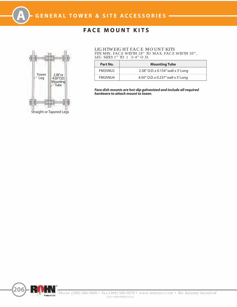
A G E N E R A L T O W E R & S I T E A C C E S S O R I E S
Phone (309) 566-3000 • Fax (309) 566-3079 • www.rohnnet.com • The Industry Standard© 2011 ROHN PRODUCTS LLC
206
F A C E M O U N T K I T S
LIGHTWEIGHT FACE MOUNT KITS
Mounting Tube
2.38“ O.D. x 0.154” wall x 5’ Long
4.50“ O.D. x 0.237” wall x 5’ Long
Part No.
FM35NU2
FM35NU4
FITS MIN. FACE WIDTH 18” TO MAX. FACE WIDTH 30”,LEG SIZES 1” TO 1 3/4” O.D.
TowerLeg
2.38” or4.50” O.D.MountingTube
Face dish mounts are hot-dip galvanized and include all requiredhardware to attach mount to tower.
Straight or Tapered Legs

Phone (309) 566-3000 • Fax (309) 566-3079 • www.rohnnet.com • The Industry Standard
G E N E R A L T O W E R & S I T E A C C E S S O R I E S
207© 2011 ROHN PRODUCTS LLC
A
Face Spread
8’ Max.
8’ Min. - 14’ Max.
Part No.
KY2016A
KY1993A
Frame Support AssemblyStraight Leg
SECTOR MOUNT ORDERING INFORMATION
Step 1. Select frame P/N based on tower face spread.
Mast
2.38” O.D. (0.154“ wall) x 5’ Long
2.38” O.D. (0.218” wall) x 8’ Long
Part No.
VY4935A
VY4935A8
Antenna Mast Kit
Step 2. Select antenna mast kits (2 min.) (1) Kit per mast tube
Standard mount shipswith (1) tie back.
3’ 5”
20’ *
(Qty. is for (1) sector only)
Face Spread
8’ Max.
8’ Min. - 14’ Max.
Part No.
KY2006A
KY2015A
Frame Support AssemblyTapered Leg
Leg O.D.
2.38” O.D.
2.88” O.D.
3.50” O.D.
4.00” O.D.
4.50” O.D.
5.56” O.D.
6.63” O.D.
8.63” O.D.
Part No.
KY1994A
KY1995A
KY1996A
KY1997A
KY1998A
KY1999A
KY2000A
KY2001A
Leg Mounting KitStraight Leg
Step 3. Select leg mounting kit.
Leg O.D.
2.38” O.D.
2.88” O.D.
3.50” O.D.
4.00” O.D.
4.50” O.D.
5.56” O.D.
6.63” O.D.
8.63” O.D.
Part No.
KY2007A
KY2008A
KY2009A
KY2010A
KY2011A
KY2012A
KY2013A
KY2014A
Leg Mounting KitTapered Leg
* Horizontal boom also availablein 12’ - 18‘ lengths (2’ increments).Add desired width to end of framesupport part number if less thana 20‘ width is desired
Example: For an 18’ width, order part numberKY2016A18. (Refer to table for step 1.)
Side View
S E C T O R M O U N T[ F O L LOW S T E P S 1 - 3 T O O R D E R ]
Step 1:Select frame P/N from
table below.
Step 2:Select antenna mast from
table below.
Step 3:Select leg
mounting kitfrom tablebelow.
6’ - 1”
Sector mounts are hot-dip galvanizedand include all required hardware toattach mount to tower. Face Spread
(See Step 1)

A G E N E R A L T O W E R & S I T E A C C E S S O R I E S
R O T O R P L A T E A S S E M B L I E S
F O R R O H N S T A N D A R D S E L F - S U P P O R T I N G T O W E R S
Phone (309) 566-3000 • Fax (309) 566-3079 • www.rohnnet.com • The Industry Standard© 2011 ROHN PRODUCTS LLC
208
4’ - 6”Mast Pipe
TB3 or TB4
Top Plate toMount TB3 or TB4 Thrust Bearing
Tower Axis
1W / 2WTower Leg
P/N: VU479A
NOTES:
1. All plates are 3/8” thick
2. Rotor top plates are pre-drilled to fit a variety of rotors.3. Rotor plate assembly includes top plate and rotor plate.4. Mast pipe, rotor and thrust bearing must be ordered separately.
Mast Pipe
TB3 or TB4
Top Plate toMount TB3 or TB4
Thrust BearingTower Axis
3WN Tower Leg
3 W N 3 W N S T / 3 W N B
5’ - 0”
Mast Pipe
TB3 or TB4
Top Plate toMount TB3
or TB4 Thrust Bearing Tower Axis
3WNST /3WNBTower
Leg
P/N: VU140P/N: VU474A
1 W / 2 W
Rotor plate accessories are hot-dip galvanized and include all required hardware to attach assemblies to tower.

Climbing Harness
S A F E T Y & C L I M B I N GG - S E R I E S T O W E R S | P O L E S
Phone (309) 566-3000 • Fax (309) 566-3079 • www.rohnnet.com • The Industry Standard
G E N E R A L T O W E R & S I T E A C C E S S O R I E S
209© 2011 ROHN PRODUCTS LLC
A
SAFETY CABLE - TOWERS
SAFETY CABLE - POLES
Description
25’ - Pole
50’ - Pole
100’ - Pole
150’ - Pole
200’ - Pole
250’ - Pole
Step Anchor Bracket
Additional 4” StudCable Guide
Cable (ft.)
35
60
110
160
210
260
-
-
Part No.
TT025TSP
TT050TSP
TT100TSP
TT150TSP
TT200TSP
TT250TSP
TTSBAB
TT115317-4
# Guides
1
2
4
6
8
10
-
-
Safety Cable Sliderwith Carabineer
Description Part Number
50’ - 25G tower
100’ - 25G tower
150’ - 25G tower
200’ - 25G tower
TT05025
TT10025
TT15025
TT20025
50’ - 45G/55G tower
100’ - 45G/55G tower
150’ - 45G/55G tower
200’ - 45G/55G tower
250’ - 45G/55G tower
300’ - 45G/55G tower
350’ - 45G/55G tower
TT0504555
TT1004555
TT1504555
TT2004555
TT2504555
TT3004555
TT3504555
Description Part Number
50’ - 65G tower
100’ - 65G tower
150’ - 65G tower
200’ - 65G tower
250’ - 65G tower
300’ - 65G tower
350’ - 65G tower
400’ - 65G tower
450’ - 65G tower
500’ - 65G tower
TT05065
TT10065
TT15065
TT20065
TT25065
TT30065
TT35065
TT40065
TT45065
TT50065
Description Part Number
4-D Ring Climbing Harness
Professional Harness
Safety Cable Slider
TTFBH-4D
TTFBH-C/P
TT-WG-500-W/SMC
Description Part Number
50’ Climbing Ladder
100’ Climbing Ladder
150’ Climbing Ladder
200’ Climbing Ladder
250’ Climbing Ladder
300’ Climbing Ladder
TT050LAD
TT100LAD
TT150LAD
TT200LAD
TT250LAD
TT300LAD
Description Part Number
SAFETY CABLE SYSTEM FORCLIMBING LADDERS - TOWERS
HARNESS & SLIDER

A G E N E R A L T O W E R & S I T E A C C E S S O R I E S
C L I M B I N G L A D D E R S
Phone (309) 566-3000 • Fax (309) 566-3079 • www.rohnnet.com • The Industry Standard© 2011 ROHN PRODUCTS LLC
210
CO N F I G U R AT I O N S
5/8” Dia.
Ladder
Rung
.25” x 1.50”
Side Rails
STANDARD LADDER
NL10 - 10’ ladder
NL20 - 20’ ladder
15” O.C.
3/4” Dia.
Ladder
Rung
.25” x 2.50”
Side Rails
HEAVY DUTY LADDER
HL161A - 10’ ladder
HL162A - 20’ ladder
12” O.C.
Face MountedInside Corner MountedLeg Mounted
Notes:
1. Ladders are available for most ROHN standard tower sections.
2. All ROHN climbing devices are indended for use by professional (competent climbers) only.
3. Specify ladder type and con!guration when ordering.
4. Custom con!gurations and mounting options available.
5. A safety climb system is required for all structures greater than 10’ in height.
Part number for ladder section only. Mounting kit must be ordered separately.

W A V E G U I D E L A D D E RF A C E M O U N T E D 9 - H O L E
Phone (309) 566-3000 • Fax (309) 566-3079 • www.rohnnet.com • The Industry Standard
G E N E R A L T O W E R & S I T E A C C E S S O R I E S
211© 2011 ROHN PRODUCTS LLC
A
Waveguide Ladder Elevation
WL20F93KD20’ Long Waveguide Ladder (3‘ rung spacing)
WL20F94KD20’ Long Waveguide Ladder (4‘ rung spacing)
WL10F93KD10’ Long Waveguide Ladder (3‘ rung spacing)
WL10F94KD10’ Long Waveguide Ladder (4’ rung spacing)
ORDERING INFORMATION
Notes:
1. Waveguide ladder may be moved horizontally for the proper alignment.
2. Waveguide ladder may be mounted inside or outside of tower as required.
Ladder Rail
Bolt Assembly
J-Bolt Assembly
Diagonal
Tower Brace
Ladder Rail
Bolt Assembly
7/16” Dia. Holes(9 Per Rung)
3/4” Dia. Holes
(9 Per Rung)
Ladder Rail
Ladder
Attachment
Clip
Diagonal Tower
Brace
1.9’
3’ or 4’
5” Max. Angle
3/8” Max. Thickness
2 1/2”

W A V E G U I D E L A D D E RF A C E M O U N T E D 1 2 - H O L E
A G E N E R A L T O W E R & S I T E A C C E S S O R I E S
Phone (309) 566-3000 • Fax (309) 566-3079 • www.rohnnet.com • The Industry Standard© 2011 ROHN PRODUCTS LLC
212
Waveguide Ladder Elevation
WL20F123KD20’ Long Waveguide Ladder (3‘ rung spacing)
WL20F124KD20’ Long Waveguide Ladder (4‘ rung spacing)
WL10F123KD10’ Long Waveguide Ladder (3‘ rung spacing)
WL10F124KD10’ Long Waveguide Ladder (4’ rung spacing)
ORDERING INFORMATION
Notes:
1. Waveguide ladder may be moved horizontally for the proper alignment.
2. Waveguide ladder may be mounted inside or outside of tower as required.
Ladder Rail
Bolt Assembly
J-Bolt Assembly
Diagonal
Tower Brace
Ladder Rail
Bolt Assembly
7/16” Dia. Holes(12 Per Rung)
3/4” Dia. Holes
(12 Per Rung)
Ladder Rail
Ladder
Attachment
Clip
Diagonal Tower
Brace
2.6’
3’ or 4’
5” Max. Angle
3/8” Max. Thickness
2 1/2”

W A V E G U I D E L A D D E RF A C E M O U N T E D 1 5 - H O L E
Phone (309) 566-3000 • Fax (309) 566-3079 • www.rohnnet.com • The Industry Standard
G E N E R A L T O W E R & S I T E A C C E S S O R I E S
213© 2011 ROHN PRODUCTS LLC
A
Waveguide Ladder Elevation
WL20F153KD20’ Long Waveguide Ladder (3‘ rung spacing)
WL20F154KD20’ Long Waveguide Ladder (4‘ rung spacing)
WL10F153KD10’ Long Waveguide Ladder (3‘ rung spacing)
WL10F154KD10’ Long Waveguide Ladder (4’ rung spacing)
ORDERING INFORMATION
Notes:
1. Waveguide ladder may be moved horizontally for the proper alignment.
2. Waveguide ladder may be mounted inside or outside of tower as required.
Ladder Rail
Bolt Assembly
J-Bolt Assembly
Diagonal
Tower Brace
Ladder Rail
Bolt Assembly
7/16” Dia. Holes
(15 Per Rung)
3/4” Dia. Holes
(15 Per Rung)
Ladder Rail
Ladder
Attachment
Clip
Diagonal Tower
Brace
2.8’
3’ or 4’
5” Max. Angle
3/8” Max. Thickness
2 1/4”

W A V E G U I D E B R A C K E T S3 - H O L E
A G E N E R A L T O W E R & S I T E A C C E S S O R I E S
Phone (309) 566-3000 • Fax (309) 566-3079 • www.rohnnet.com • The Industry Standard© 2011 ROHN PRODUCTS LLC
214
Waveguide Bracket Elevation
KY2041A
ORDERING INFORMATION
Notes:
1. Kit includes (1) bracket with required mounting hardware.
2. Assembly used for mounting to 3/4” - 2 1/4” O.D. legs.
3. (5) KY2041A required per 20’ of tower for 4’ O.C. spacing.
KY2041A
(3) 7/16” holes
(3) 3/4” holes
2 1/4”

W A V E G U I D E B R A C K E T S8 - H O L E ( 8 0 S E R I E S )
Phone (309) 566-3000 • Fax (309) 566-3079 • www.rohnnet.com • The Industry Standard
G E N E R A L T O W E R & S I T E A C C E S S O R I E S
215© 2011 ROHN PRODUCTS LLC
A
WAF801213(Horizontals)
Order 1 per 15’ or 20’ section
WAF801214(2” Diagonals)
Order 3 per 15’ sectionOrder 4 per 20’ section
WAF801215(1 3/4” Diagonals)
Order 3 per 15’ sectionOrder 4 per 20’ section
ORDERING INFORMATION
Bolt Assembly
DiagonalWaveguide
Brace Bracket
Horizontal WaveguideBrace Bracket
Bolt AssemblyBolt Assembly
HorizontalWaveguide
Brace Bracket
U-Bolt Assembly
DiagonalWaveguide
Brace Bracket
WAF801211(Horizontals)
Order 1 per 15’ or 20’ section
WAF801212(Diagonals)
Order 3 per 15’ sectionOrder 4 per 20’ section
ORDERING INFORMATION
7/16” hole (12 Holes Per Bracket)
3/4” hole (12 Holes Per Bracket)
Diagonal Tower
Brace (TYP)
Tower Leg
(TYP)
Standard ROHN
brace with
pre-punched
holes for bracket
attachment
2 1/4” Spacing
Tubular Bracing1 1/2” Diameter
Angle Bracing1 3/4” x 3/16“
2” x 1/4”
Tower Leg
(TYP)
NOTE: These assemblies may be mounted on the inside or outside face of the tower.

W A V E G U I D E B R A C K E T S1 5 - H O L E ( 9 0 S E R I E S )
A G E N E R A L T O W E R & S I T E A C C E S S O R I E S
Phone (309) 566-3000 • Fax (309) 566-3079 • www.rohnnet.com • The Industry Standard© 2011 ROHN PRODUCTS LLC
216
WAF901521Angle Waveguide Support
& Bolt Assembly
ORDERING INFORMATION
Order (1) assembly part number WAF901521 for each diagonal brace bay
that waveguides cross in a section. (Ex. (5) WAF901521 for a 20’ tower
section, (3) WAF901521 for a 12’ tower section, etc.). This assembly may
be mounted on outside of tower as shown or on inside as required.
Diagonal TowerBrace
Diagonal WaveguideBrace Bracket
7/16” Holes @ 2.25” Horizontal Spacing (14 Holes Per Support)
Tower Leg
3/4” Holes @ 2.25” HorizontalSpacing (15 Holes Per Support)
Bolt Assembly
2” Spacing
Angle Bracing

H E A V Y D U T Y W A V E G U I D E B R I D G E1 0 ’ S I N G L E / D O U B L E
Phone (309) 566-3000 • Fax (309) 566-3079 • www.rohnnet.com • The Industry Standard
G E N E R A L T O W E R & S I T E A C C E S S O R I E S
217© 2011 ROHN PRODUCTS LLC
A
WGBS2410Single Wide Bridge
2 Posts, 1 Bridge Panel (24” W x10’ L)(3) Trapeze Units
WGBD2410Double Bridge
2 Posts, 2 Bridge Panels (24” W x 10’ L, each)(6) Trapeze Units
ORDERING INFORMATION
Notes:
1. Waveguide bridge is not designed to support personnel or equipment.
Ground Line
Support Post4” O.D. Tube
18’ Long
DiagonalBrace Angle
PanelSupport
Angle
10’
12’ Max
4’ Min. Into Undisturbed
Soil
3” Into Gravel 6” Gravel Drain
7’
Space as Required(3 Trapeze Units
provided with eachWaveguide Bridge)
(8) 7/16” O Holes(9) 3/4” O Holes2 1/4” O.C. Hole Spacing
Units bolt togetherin field
24”
10’
Single
Double
Waveguide Panels
ThreadedRod Hangers
Trapeze

A G E N E R A L T O W E R & S I T E A C C E S S O R I E S
Phone (309) 566-3000 • Fax (309) 566-3079 • www.rohnnet.com • The Industry Standard© 2011 ROHN PRODUCTS LLC
218
L I G H T D U T Y W A V E G U I D E B R I D G E1 0 ’ S I N G L E / D O U B L E
WGBS121014Single Wide Bridge
2 Posts, 1 Bridge Panel (12” W x10’ L)(3) Trapeze Units
WGBD121014Double Bridge
2 Posts, 2 Bridge Panels (12” W x 10’ L, each)(6) Trapeze Units
ORDERING INFORMATION
Notes:
1. Waveguide bridge is not designed to support personnel or equipment.
Ground Line
Support Post4” O.D. Tube14’ Long
10’
10’ Max
4’ Min. IntoUndisturbed
Soil
3” Into Gravel 6” Gravel Drain
7’
12”
10’
(3) 7/16” O Holes(4) 3/4” O Holes2 1/4” O.C. Hole Spacing
Single
Double
Units bolt togetherin field
Waveguide Panels
Trapeze
Panel
Support
Angle
ThreadedRod Hangers
Space as Required(3 Trapeze Units provided with eachWaveguide Bridge)


Phone (309) 566-3000 • Fax (309) 566-3079 • www.rohnnet.com • The Industry Standard
P D I R E C T E M B E D P O L E S
D I R E C T E M B E D P O L E
S T A N D A R D D E S I G N S
220
© 2011 ROHN PRODUCTS LLC
180º
270º90º
Safety Climb Support Bracket(Safety Cable System Ordered Separately)
0º
C
D
A B
PORT ORIENTATIONS
8’ Separation
Splice
4’ 3”
AggregateBackfill
2’
Embedment
Bearing Plate(Allows Drainage)
Port A
Port B
Port C
Port D
Cap Plate
(3) Jacking Lugs
Pole HeightAbove Grade
6” Gravel Base
1’ 3”
GENERAL USE
ROHN Direct Embed Poles minimize site
requirements, lowering lease rates and acquisition
costs. They are designed for rapid installation,
meeting the demands of today’s dynamic
communication environments. Whether you are
supporting broadband, PCS, security or other
lightweight systems, ROHN Tapered Steel Poles
o!er extremely e#cient designs.
FEATURES
• Completely hot-dip galvanized after fabrication
• Fast, easy installation
• Designed for applications with stringent de$ection
requirements
• Internal routing of transmission lines
• Each pole ships with the following:
• Assembly Drawings and Standard Foundation Details
• (4) 5” x 7” Ports with (2) port covers
• (3) Jacking Lugs on each side of splices
• (3) Ground attachment clips
• (1) Vented cap plate
• (1) Bearing plate welded to bottom
• Safety Climb Support Brackets
• (1) Safety warning sign
• (1) Pole ID tag
• Attachment clips for optional step bolts
• Optional items are available and may be ordered
separately. Please see accessories on page 225.
• Custom designs available for any height or
application.
DIRECT EMBEDPOLES
Grade
Per Rev G requirements, any structure greater than 10’ requires a climber safety device. Please see page 225 for ordering information.
Ground Attachment Clips

221Phone (309) 566-3000 • Fax (309) 566-3079 • www.rohnnet.com • The Industry Standard
© 2011 ROHN PRODUCTS LLC
PD I R E C T E M B E D P O L E S
Part Number forordering directembed poles
Sway at TIAoperationalwind speed
Total effective projected area of antennas, mountsand lighting allowed on pole (see pg. 226)
LIGHT MEDIUM HEAVY
SWAY LIMIT SWAY LIMIT SWAY LIMIT
WIND SPEED (MPH)
FASTEST MILE
3-SECONDGUST
70
80
90
100
110120
85100
110
120
130
140
4º
69
52
38
271913
3º
49
49
38
2719
13
2º
29
29
2927
19
13
4º
110
80
59
4432
24
3º
108
80
59
4432
24
2º
68
68
59
4432
24
4º
170
126
9574
57
45
3º
170
126
9574
57
45
2º
143126
95
74
57
45
30
’
EMBEDMENT DEPTH DIA.10’ 2.5’ DEPTH DIA.11’ 2.5’ DEPTH DIA.13’ 3.0’
EPA (FT )2 EPA (FT )2 EPA (FT )2
DEP30HADEP30MADEP30LA
Depth and diameter of embedment for gravelbackfill. Installationadds 6” to the depthfor gravel base
B U Y E R S G U I D E
L O A D I N G C H A R T S
LIGHT MEDIUM HEAVY
SWAY LIMIT SWAY LIMIT SWAY LIMITWIND SPEED (MPH)
FASTEST MILE
3-SECONDGUST
70
80
90
100
110
120
85
100
110
120
130
140
4º
69
52
38
27
19
13
3º
49
49
38
27
19
13
2º
29
29
29
27
19
13
4º
110
80
59
44
32
24
3º
108
80
59
44
32
24
2º
68
68
59
44
32
24
4º
170
126
95
74
57
45
3º
170
126
95
74
57
45
2º
143
126
95
74
57
45
40
’
EMBEDMENT DEPTH DIA.12’ 2.5’ DEPTH DIA.13’ 2.5’ DEPTH DIA.15’ 3.0’
EPA (FT )2 EPA (FT )2 EPA (FT )2
DEP40HADEP40MADEP40LA
LIGHT MEDIUM HEAVY
SWAY LIMIT SWAY LIMIT SWAY LIMIT
WIND SPEED (MPH)
FASTEST MILE
3-SECONDGUST
70
80
90
100
110
120
85
100
110
120
130
140
4º
69
52
38
27
19
13
3º
49
49
38
27
19
13
2º
29
29
29
27
19
13
4º
110
80
59
44
32
24
3º
108
80
59
44
32
24
2º
68
68
59
44
32
24
4º
170
126
95
74
57
45
3º
170
126
95
74
57
45
2º
143
126
95
74
57
45
50
’
EMBEDMENT DEPTH DIA.15’ 2.5’ DEPTH DIA.16’ 2.5’ DEPTH DIA.17’ 3.0’
EPA (FT )2 EPA (FT )2 EPA (FT )2
DEP50HADEP50MADEP50LA
The pole loading charts included in this section were created to help you identify the standard pole that most closely meets
your needs. The charts include the design wind speed, sway, total EPA that the pole can support and pole embedment
requirements. Once the correct structure is identified, use the part number at the top of each section to order your pole.
HeightAboveGrade

Phone (309) 566-3000 • Fax (309) 566-3079 • www.rohnnet.com • The Industry Standard
P D I R E C T E M B E D P O L E S
222
© 2011 ROHN PRODUCTS LLC
L O A D I N G C H A R T S
LIGHT MEDIUM HEAVY
SWAY LIMIT SWAY LIMIT SWAY LIMITWIND SPEED (MPH)
FASTEST MILE
3-SECONDGUST
70
80
90
100
110
120
85100
110
120
130
140
4º
28
28
19
9
2
-
3º
17
17
17
9
2
-
2º
6
6
6
6
2
-
4º
65
50
32
19
9
2
3º
44
44
32
19
9
2
2º
23
2323
19
9
2
4º
117
8258
41
28
18
3º
93
82
58
41
28
18
2º
56
56
56
41
28
18
LIGHT MEDIUM HEAVY
SWAY LIMIT SWAY LIMIT SWAY LIMIT
WIND SPEED (MPH)
FASTEST MILE
3-SECONDGUST
70
80
90
100
110
120
85
100
110120
130
140
4º
21
2114
4-
-
3º
11
11
11
4-
-
2º
22
2
2
2
-
4º
51
43
25
12
3
-
3º
33
33
25
12
3
-
2º
16
16
16
12
3
-
4º
106
73
50
33
21
13
3º
77
73
50
33
21
13
2º
44
44
4433
21
13
80
’9
0’
EMBEDMENT DEPTH DIA.16’ 3.0’ DEPTH DIA.18’ 3.0’ DEPTH DIA.20’ 3.5’
EMBEDMENT DEPTH DIA.18’ 3.0’ DEPTH DIA.20’ 3.0’ DEPTH DIA.22’ 3.5’
LIGHT MEDIUM HEAVY
SWAY LIMIT SWAY LIMIT SWAY LIMITWIND SPEED (MPH)
FASTEST MILE
3-SECONDGUST
70
80
90
100
110
120
85100
110
120
130
140
4º
42
42
28
17
9
3
3º
28
2828
17
9
3
2º
13
13
13
13
9
3
4º
89
63
43
29
19
10
3º
63
63
43
29
19
10
2º
36
36
36
29
19
10
4º
137
98
72
53
39
28
3º
129
98
73
53
39
28
2º
81
81
73
53
39
28
70
’
EMBEDMENT DEPTH DIA.16’ 3.0’ DEPTH DIA.18’ 3.0’ DEPTH DIA.20’ 3.5’
EPA (FT )2 EPA (FT )2 EPA (FT )2
DEP70HADEP70MADEP70LA
EPA (FT )2 EPA (FT )2 EPA (FT )2
DEP80HADEP80MADEP80LA
EPA (FT )2 EPA (FT )2 EPA (FT )2
DEP90HADEP90MADEP90LA
LIGHT MEDIUM HEAVY
SWAY LIMIT SWAY LIMIT SWAY LIMITWIND SPEED (MPH)
FASTEST MILE
3-SECONDGUST
70
80
90
100
110
120
85
100
110
120
130
140
4º
52
46
32
21
14
8
3º
35
35
32
21
14
8
2º
19
19
19
19
14
8
4º
99
71
50
36
25
17
3º
80
71
50
36
25
17
2º
48
48
48
36
25
17
4º
150
109
81
61
46
35
3º
150
109
81
61
46
35
2º
104
104
81
61
46
35
60
’
EMBEDMENT DEPTH DIA.15’ 2.5’ DEPTH DIA.17’ 3.0’ DEPTH DIA.19’ 3.0’
EPA (FT )2 EPA (FT )2 EPA (FT )2
DEP60HADEP60MADEP60LA
( - ) Indicates that pole is not recommended for the tabulated wind speed

223Phone (309) 566-3000 • Fax (309) 566-3079 • www.rohnnet.com • The Industry Standard
© 2011 ROHN PRODUCTS LLC
PD I R E C T E M B E D P O L E S
L O A D I N G C H A R T S
LIGHT MEDIUM HEAVY
SWAY LIMIT SWAY LIMIT SWAY LIMIT
WIND SPEED (MPH)
FASTEST MILE
3-SECONDGUST
70
8090
100
110120
85
100110
120130
140
4º
19
1914
2
-
-
3º
88
82
-
-
2º
--
--
-
-
4º
39
3924
11
--
3º
2424
2411
-
-
2º
6
66
6
-
-
4º
83
76
5132
21
10
3º
57
5751
32
2110
2º
30
3030
30
2110
13
0’
EMBEDMENT DEPTH DIA.22’ 4.0’ DEPTH DIA.23’ 4.0’ DEPTH DIA.24’ 4.5’
LIGHT MEDIUM HEAVY
SWAY LIMIT SWAY LIMIT SWAY LIMITWIND SPEED (MPH)
FASTEST MILE
3-SECONDGUST
708090100
110120
85100110120
130140
4º
18185
-
--
3º
10
105-
-
-
2º
--
-
-
-
-
4º
3936
15-
-
-
3º
2424
15-
-
-
2º
666
-
-
-
4º
908055
36
2314
3º
62625536
23
14
2º
35353535
23
14
12
0’
EMBEDMENT DEPTH DIA.19’ 3.5’ DEPTH DIA.22’ 4.0’ DEPTH DIA.23’ 4.0’
EPA (FT )2 EPA (FT )2 EPA (FT )2
DEP120HADEP120MADEP120LA
EPA (FT )2 EPA (FT )2 EPA (FT )2
DEP130HADEP130MADEP130LA
LIGHT MEDIUM HEAVY
SWAY LIMIT SWAY LIMIT SWAY LIMIT
WIND SPEED (MPH)
FASTEST MILE
3-SECONDGUST
708090100
110120
85100110120
130
140
4º
2323
13---
3º
131313---
2º
------
4º
514725
9--
3º
3232259--
2º
1414149
--
4º
103775031178
3º
7070
50
31178
2º
41414131178
11
0’
EMBEDMENT DEPTH DIA.19’ 3.5’ DEPTH DIA.21’ 4.0’ DEPTH DIA.22’ 4.0’
EPA (FT )2 EPA (FT )2 EPA (FT )2
DEP110HADEP110MADEP110LA
LIGHT MEDIUM HEAVY
SWAY LIMIT SWAY LIMIT SWAY LIMIT
WIND SPEED (MPH)
FASTEST MILE
3-SECONDGUST
708090100110120
85
100110
120130140
4º
1616
9---
3º
777
---
2º
------
4º
4236186
--
3º
2626
186-
-
2º
11
11116--
4º
9165432614
7
3º
63634326
147
2º
363636
2614
7
10
0’
EMBEDMENT DEPTH DIA.18’ 3.0’ DEPTH DIA.20’ 3.5’ DEPTH DIA.22’ 3.5’
EPA (FT )2 EPA (FT )2 EPA (FT )2
DEP100HADEP100MADEP100LA
( - ) Indicates that pole is not recommended for the tabulated wind speed

Phone (309) 566-3000 • Fax (309) 566-3079 • www.rohnnet.com • The Industry Standard
P D I R E C T E M B E D P O L E S
224
© 2011 ROHN PRODUCTS LLC
L O A D I N G C H A R T S
1. Pole designs conform to ANSI/TIA/EIA-222-F with 1/2” radial ice and to ANSI/TIA-222-G (Class I, Exposure B, Topographic
Catagory I ). Design criteria must be verified prior to installation based on site-specific requirements.
2. Embedment depths are based on “Normal” soil (TIA Rev. F) and clay “Presumptive” soil (TIA Rev. G) with aggregate backfill.
Actual site soil design parameters must be verified prior to installation.
3. For corrosive groundwater and/or soil conditions, ROHN recommends additional corrosion control protection such as concrete
backfill, additional protective coating over galvanizing or the installation of sacrificial anodes.
4. Embedment depths may require adjustment based on local soil conditions.
( - ) Indicates that pole is not recommended for the tabulated wind speed
LIGHT MEDIUM HEAVY
SWAY LIMIT SWAY LIMIT SWAY LIMIT
WIND SPEED (MPH)
FASTEST MILE
3-SECONDGUST
708090100110120
85100110120130140
4º
17
1717---
3º
555-
--
2º
--
-
---
4º
47473010-
-
3º
26262610--
2º
6666--
4º
89
89
6539226
3º
63
636339226
2º
3131
3131226
15
0’
LIGHT MEDIUM HEAVY
SWAY LIMIT SWAY LIMIT SWAY LIMIT
WIND SPEED (MPH)
FASTEST MILE
3-SECONDGUST
70
80
90
100
110
120
85
100
110
120
130
140
4º
16
16
8
-
-
-
3º
5
5
5
-
-
-
2º
-
-
-
-
-
-
4º
42
42
36
16
-
-
3º
26
26
26
16
-
-
2º
6
6
6
6
-
-
4º
86
86
66
45
28
13
3º
62
62
62
45
28
13
2º
31
31
31
31
28
13
14
0’
EMBEDMENT DEPTH DIA.24’ 4.0’ DEPTH DIA.25’ 4.5’ DEPTH DIA.26’ 4.5’
EMBEDMENT DEPTH DIA.24’ 4.0’ DEPTH DIA.26’ 4.5’ DEPTH DIA.27’ 5.0’
EPA (FT )2 EPA (FT )2 EPA (FT )2
DEP140HADEP140MADEP140LA
EPA (FT )2 EPA (FT )2 EPA (FT )2
DEP150HADEP150MADEP150LA

225Phone (309) 566-3000 • Fax (309) 566-3079 • www.rohnnet.com • The Industry Standard
© 2011 ROHN PRODUCTS LLC
PD I R E C T E M B E D P O L E S
Pole Height
30’ - 50’
60’ - 100’
110’ - 150’
Part Number
TT050TSP
TT100TSP
TT150TSP
15”
Grounding Lug Ground Wire
Ground RodGround Rod Clamp
Grade
P A R T S & A C C E S S O R I E S
STEP BOLTS
STEP BOLTS START AT 20’ ABOVEGRADE (NOMINAL). WHEN
ORDERING STEP BOLTS, PLEASESPECIFY POLE HEIGHT.
EX. SBDEP120 for a 120’ POLE
JOURNEYMANCLIMBING HARNESS
TTFBH-4D
PROFESSIONALCLIMBING HARNESS
TTFBH-C/P
SAFETY CABLE SLIDERWITH CARABINEERTT-WG-500-W/SMC
SAFETY CABLE SYSTEM
LIGHTNING RODLRCL
5’ COPPER CLADBOLTS TO CAP PLATE, PROVIDED
WITH POLE.
5.00
7.00ReferenceElevation
Internal HookFor Ports C-D
A through D PORTSLarger ports are available, upon request.
P O R T D I M E N S I O N S
Cap Plate
GROUNDING KITBGK5GGX
KIT INCLUDES (1) GROUND LEAD, GROUND ROD AND CONNECTIONS.ORDER (3) KITS FOR REV G GROUNDING.

Phone (309) 566-3000 • Fax (309) 566-3079 • www.rohnnet.com • The Industry Standard
P D I R E C T E M B E D P O L E S
A N T E N N A I N D E X
226© 2011 ROHN PRODUCTS LLC
FLAT PANEL ANTENNA
DIMENSION SWAY LIMIT2511
4º2º2º
EPA - FT
1 FT. SQUARE W/ MOUNT2 FT. SQUARE W/ MOUNT3 FT. SQUARE W/ MOUNT
DISH ANTENNA
DIAMETEREPA - FT
SWAY LIMIT
371151119
6132281834
4º3º2º4º3º2º
W/ RADOME W/O RADOME
(1) 2 FT.(1) 3FT.(1) 4FT.
(2) 2 FT. B-TO-B(2) 3 FT. B-TO-B(2) 4 FT. B-TO-B
1. The above antenna data is intended to assist in the selection of the appropriate ROHN pole. Once the total EPA and sway limit
is determined for the antennas, the standard ROHN pole can be selected from the tabulated values. (See example below)
2. Tabulated pole EPA capacities represent the maximum EPA capacity of a pole. The capacity is based on the assumption that 80%
of the total EPA is located at the top of the pole and the remaining 20% is located 20 ft. below the top. When all loading is located
at the top of the pole, the tabulated EPA capacity must be reduced by 20%.
3. Sway limits are determined under a 50 MPH fastest-mile (Rev. F) or 60 MPH 3-second gust (Rev. G) wind speed.
4. The antenna effective projected areas (EPA) and sway limits provided in the antenna index are guidelines for typical antenna
systems. Other values may apply for specific antenna models or for site-specific systems.
2 2
1. Using the antenna index, determine the types of antennas to be installed on the pole.
2. Add together the EPA value of all the antennas to be supported.
3. Determine the most restrictive sway limit considering all the antennas to be supported. For example, for one
3’ dish with a 3º sway limit and one 1’ flat panel with a 4º sway limit, the sway limit for the pole would be 3º and
the required pole EPA capacity would be 13+2=15 ft .
4. If all antennas are to be supported at the top of the pole, only 80% of the tabulated EPA capacity shown may be
considered when selecting a pole. Alternately, the antenna EPA to be supported may be increased by 25%. For example,
the required pole capacity would be 15x1.25=19 ft .
5. Using the pole sway limit and the required EPA capacities, the appropriate pole may be determined from the tabulated
values. For example, for a 120 ft. pole and a 100 mph 3-sec gust wind speed, a medium pole [P/N: DEP120MA] would be
required for an EPA capacity greater than 19 ft for a 3º sway limit.
2
2
2
Determine EPA & Sway Limit for Dishes or Flat Panel Antennas

227Phone (309) 566-3000 • Fax (309) 566-3079 • www.rohnnet.com • The Industry Standard
© 2011 ROHN PRODUCTS LLC
PU T I L I T Y P O L E S
P R E - E N G I N E E R E D U T I L I T Y P O L E S
GENERAL USE
ROHN Pre-Engineered steel utility poles o!er a
light duty solution to satisfy utilities desiring an
alternative to wood poles. ROHN’s line of
Pre-Engineered poles are lighter than typical
wooden and concrete poles and provide easy
installation and low maintenance. ROHN o!ers
Pre-Engineered poles for either direct embed or
#ange installations. The poles come standard with
a hot-dip galvanized coating, but can also be
painted or fabricated with weathering steel.
FEATURES
• Fast, easy installation
• Each pole ships with the following:
• Standard ground sleeve (at grade)
• Standard sub-grade corrosion coating
to 6” above grade
• Cap plate
• (2) 4” Nema Ground Lugs
• Bearing Plate with drain hole
• Jacking Lugs (at slip splices)
• Optional items are available and may be ordered
separately:
• Step attachment clips
• Climbing pegs / step bolts
• Safety climb device
• Port holes
• Flanged base
• Painted $nish
• Custom designs are available for any height
or application.
PRE-ENGINEEREDUTILITY POLES

Phone (309) 566-3000 • Fax (309) 566-3079 • www.rohnnet.com • The Industry Standard
P U T I L I T Y P O L E S
228© 2011 ROHN PRODUCTS LLC
B U Y E R S G U I D E
H 1 0 R P 0 5 0 W
Pole Loading
ROHNProducts
Overall Pole Length (ft.)
Pole Finish, select either:
- Weathering
- Galvanized
The part number shown in the chart includes the pole loading and the overall length of the structure. The coating su!x (W or G) is added by the customer at the time of the order, along with any optional
items (#anged base, step clips and safety device, ports, special grounding lugs, special ground sleeves and paint).
The example below provides a guide, for ordering convenience.
Diameters are out-to-out width between #ats. Slope is change in diameter per foot of length. Overturning moment capacity is at grade.
In the example shown, the customer is purchasing an H10RP, with an overall length of 50’. The pole is to be constructed of Weathering Steel, with a Direct Embed Base.
NOTE: Values in ( ) indicate horizontal factored loads applied 2’ from the tip.
Embedment depths illustrated may require adjustment based on local soil conditions.
Pole Part Number Finish
H 1 0 R P ( 18,400# / 11,500#)
Factored load for steel polesEquivalent factored load
for wood poles
OVERTURNINGTIP BASE
MOMENTDIAMETER DIAMETER SLOPE NO. WEIGHT
CAPACITY(IN) (IN) SECTIONS (LBS)
(FT-KIP)
H 1 0 R P (18,400# / 11,500#)
TOTAL
LENGTH
(FT) “L”
404550556065707580859095
100105110115120
21.222.423.525.126.327.628.830.131.332.633.834.435.736.938.239.440.7
PART
NUMBER
H10RP040H10RP045H10RP050H10RP055H10RP060H10RP065H10RP070H10RP075H10RP080H10RP085H10RP090H10RP095H10RP100H10RP105H10RP110H10RP115H10RP120
12.012.012.012.012.012.012.012.012.012.012.012.012.012.012.012.012.0
0.2300.2310.2300.2380.2380.2400.2400.2410.2410.2420.2420.2360.2370.2370.2380.2380.239
11122222222333333
19452253258130743440389643044765521056666148677972827918845991539731
368420472523576627680730785834890937995
1041110011411206
OT
M @
5’ =
18
3 ft-k
ips
(IN/FT)
34.038.543.047.552.056.561.065.570.074.579.083.588.092.597.0
101.5106.0
TIP
AGL
(FT)
Overturning moment capacity at 5’ below tip.

7.5” Tip
13.1” - 27.5”Base Diameter
Embedment(L x .10) + 2’
229Phone (309) 566-3000 • Fax (309) 566-3079 • www.rohnnet.com • The Industry Standard
© 2011 ROHN PRODUCTS LLC
P R O D U C T D A T A
PU T I L I T Y P O L E S
OVERTURNINGTIP BASE
MOMENTDIAMETER DIAMETER SLOPE NO. WEIGHT
CAPACITY(IN) (IN) SECTIONS (LB)
(FT-KIP)
C 1 R P (4,500# / 2,812#)
TIP
AGL
(FT)
34.038.543.047.552.056.561.065.570.074.579.083.588.092.597.0
101.5106.0
13.113.113.114.814.817.217.219.519.521.321.323.723.725.725.727.527.5
PART
NUMBER
C1RP040C1RP045C1RP050C1RP055C1RP060C1RP065C1RP070C1RP075C1RP080C1RP085C1RP090C1RP095C1RP100C1RP105C1RP110C1RP115C1RP120
7.57.57.57.57.57.57.57.57.57.57.57.57.57.57.57.57.5
0.1400.1240.1120.1330.1220.1490.1390.1600.1500.1620.1530.1710.1620.1730.1650.1740.167
11122222222333333
9811092120114421553187619992337247728402937340335604033419746434820
91103117128143153169179196204223229250267277280305
OVERTURNINGTIP BASE
MOMENTDIAMETER DIAMETER SLOPE NO. WEIGHT
CAPACITY(IN) (IN) SECTIONS (LB)
(FT-KIP)
C 2 R P (3,700# / 2,313#)
TOTAL
LENGTH
(FT) “L”
404550556065707580859095
100105110115120
13.114.514.515.915.917.317.318.718.720.120.122.022.023.723.725.525.5
PART
NUMBER
C2RP040C2RP045C2RP050C2RP055C2RP060C2RP065C2RP070C2RP075C2RP080C2RP085C2RP090C2RP095C2RP100C2RP105C2RP110C2RP115C2RP120
7.57.57.57.57.57.57.57.57.57.57.57.57.57.57.57.57.5
0.1400.1560.1400.1530.1400.1510.1400.1490.1400.1480.1400.1530.1450.1540.1470.1570.150
11122222222333333
9811161127715051629188220072274240626742818322233683774392843834547
758496
105116137147157168178189199209215220230241
OVERTURNINGTIP BASE
MOMENTDIAMETER DIAMETER
SLOPE NO. WEIGHTCAPACITY
(IN) (IN) SECTIONS (LB)(FT-KIP)
C 3 R P (3,000# / 1,875#)
TOTAL
LENGTH
(FT) “L”
404550556065707580859095
100105110115120
13.114.514.515.915.917.317.318.718.720.120.121.521.522.922.924.324.3
PART
NUMBER
C3RP040C3RP045C3RP050C3RP055C3RP060C3RP065C3RP070C3RP075C3RP080C3RP085C3RP090C3RP095C3RP100C3RP105C3RP110C3RP115C3RP120
7.57.57.57.57.57.57.57.57.57.57.57.57.57.57.57.57.5
0.1400.1560.1400.1530.1400.1510.1400.1490.1400.1480.1400.1470.1400.1470.1400.1460.140
11122222222333333
9811161127715051626188220072274240626772818316933123678382842244384
6168788596
102113119131136144153161170178187195
OT
M @
5’ =
51
ft-kip
sO
TM
@ 5
’ = 5
3 ft-k
ips
OT
M @
5’ =
53
ft-kip
s(IN/FT)
(IN/FT)
(IN/FT)
TOTAL
LENGTH
(FT) “L”
404550556065707580859095
100105110115120
34.038.543.047.552.056.561.065.570.074.579.083.588.092.597.0
101.5106.0
34.038.543.047.552.056.561.065.570.074.579.083.588.092.597.0
101.5106.0
TIP
AGL
(FT)
TIP
AGL
(FT)

Phone (309) 566-3000 • Fax (309) 566-3079 • www.rohnnet.com • The Industry Standard
P U T I L I T Y P O L E S
230© 2011 ROHN PRODUCTS LLC
P R O D U C T D A T A
7.5” - 8” Tip
13.1” - 33”Base Diameter
Embedment(L x .10) + 2’
OVERTURNINGTIP BASE
MOMENTDIAMETER DIAMETER SLOPE NO. WEIGHT
CAPACITY(IN) (IN) SECTIONS (LB)
(FT-KIP)
H 1 R P (5,400# / 3,375#)
TOTAL
LENGTH
(FT) “L”
404550556065707580859095
100105110115120
13.114.214.216.016.018.518.521.021.023.023.026.026.028.028.029.529.5
PART
NUMBER
H1RP040H1RP045H1RP050H1RP055H1RP060H1RP065H1RP070H1RP075H1RP080H1RP085H1RP090H1RP095H1RP100H1RP105H1RP110H1RP115H1RP120
7.57.57.57.57.57.57.57.57.57.57.57.57.57.57.57.57.5
0.1400.1490.1340.1550.1420.1690.1570.1800.1690.1820.1720.1950.1850.1950.1860.1910.183
11122222222333333
9811161126115161636196621022465261129523092370538724309448849505133
109138140153171184202214234245246278298305330336363
OVERTURNINGTIP BASE
MOMENTDIAMETER DIAMETER
NO. WEIGHTCAPACITY
(IN) (IN) SECTIONS (LB)(FT-KIP)
H 2 R P (6,400# / 4,000#)
TOTAL
LENGTH
(FT) “L”
404550556065707580859095
100105110115120
13.616.016.017.517.519.419.422.022.024.524.527.327.329.429.431.431.4
PART
NUMBER
H2RP040H2RP045H2RP050H2RP055H2RP060H2RP065H2RP070H2RP075H2RP080H2RP085H2RP090H2RP095H2RP100H2RP105H2RP110H2RP115H2RP120
7.87.87.87.87.87.87.87.87.87.87.87.87.87.87.87.87.8
0.1450.1820.1640.1760.1620.1780.1660.1890.1780.1960.1860.2050.1950.2060.1960.2050.197
11122222222333333
10161251137516381765205621942592274431383304388040554510469852365433
129146165182202
218239254277290314326352362390398428
OVERTURNINGTIP BASE
MOMENTDIAMETER DIAMETER
NO. WEIGHTCAPACITY
(IN) (IN) SECTIONS (LB)(FT-KIP)
H 3 R P (7,500# / 4,688#)
TOTAL
LENGTH
(FT) “L”
404550556065707580859095
100105110115120
14.817.017.018.818.821.021.023.223.226.026.028.628.631.231.233.033.0
PART
NUMBER
H3RP040H3RP045H3RP050H3RP055H3RP060H3RP065H3RP070H3RP075H3RP080H3RP085H3RP090H3RP095H3RP100H3RP105H3RP110H3RP115H3RP120
8.08.08.08.08.08.08.08.08.08.08.08.08.08.08.08.08.0
0.1700.2000.1800.1960.1800.2000.1860.2030.1900.2120.2000.2170.2060.2210.2110.2170.208
11122222222333333
10771309144017281865218423352708287033023475404442264775497354805684
150171193213235255278298321340365382407424451466494
OT
M @
5’ =
52
ft-kip
sO
TM
@ 5
’ = 5
7 ft-k
ips
OT
M @
5’ =
62
ft-kip
s
(IN/FT)
SLOPE
(IN/FT)
SLOPE
(IN/FT)
34.038.543.047.552.056.561.065.570.074.579.083.588.092.597.0
101.5
106.0
34.038.543.047.552.056.561.065.570.074.579.083.588.092.597.0
101.5106.0
34.038.543.047.552.056.561.065.570.074.579.083.588.092.597.0
101.5106.0
TIP
AGL
(FT)
TIP
AGL
(FT)
TIP
AGL
(FT)

8.5” - 9” Tip
16.5” - 38.5”Base Diameter
Embedment(L x .10) + 2’
231Phone (309) 566-3000 • Fax (309) 566-3079 • www.rohnnet.com • The Industry Standard© 2011 ROHN PRODUCTS LLC
P R O D U C T D A T A
PU T I L I T Y P O L E S
OVERTURNINGTIP BASEMOMENTDIAMETER DIAMETER NO. WEIGHT
CAPACITY(IN) (IN) SECTIONS (LB)(FT-KIP)
H 4 R P (8,700# / 5,438#)TOTAL
LENGTH(FT) “L”
404550556065707580859095
100105110115120
16.518.218.220.220.222.222.224.324.327.227.230.030.032.332.334.934.9
PARTNUMBER
H4RP040H4RP045H4RP050H4RP055H4RP060H4RP065H4RP070H4RP075H4RP080H4RP085H4RP090H4RP095H4RP100H4RP105H4RP110H4RP115H4RP120
8.58.58.58.58.58.58.58.58.58.58.58.58.58.58.58.58.5
0.2000.2160.1940.2130.1950.2110.1960.2110.1980.2200.2080.2260.2150.2270.2160.2300.220
11122222222333333
11161336147617861935225324102788295634033589417143654929513757665985
174199223247273296322345372394421443471492522541572
OVERTURNINGTIP BASEMOMENTDIAMETER DIAMETER NO. WEIGHT
CAPACITY(IN) (IN) SECTIONS (LB)(FT-KIP)
H 5 R P (10,000# / 6,250#)TOTAL
LENGTH(FT) “L”
404550556065707580859095
100105110115120
17.520.020.022.022.024.324.326.526.529.029.031.731.734.334.337.037.0
PARTNUMBER
H5RP040H5RP045H5RP050H5RP055H5RP060H5RP065H5RP070H5RP075H5RP080H5RP085H5RP090H5RP095H5RP100H5RP105H5RP110H5RP115H5RP120
9.09.09.09.09.09.09.09.09.09.09.09.09.09.09.09.09.0
0.2130.2440.2200.2360.2170.2350.2190.2330.2190.2350.2220.2390.2270.2410.2300.2430.233
11122222222333333
11811447160119292090245926313016319836253820443646405231544961376365
200228257284314341371397429453487509545566603622662
OVERTURNINGTIP BASEMOMENTDIAMETER DIAMETER NO. WEIGHT
CAPACITY(IN) (IN) SECTIONS (LB)(FT-KIP)
H 6 R P (11,400# / 7,125#)TOTAL
LENGTH(FT) “L”
404550556065707580859095
100105110115120
18.321.021.023.223.425.725.928.328.330.830.833.433.437.037.038.538.5
PARTNUMBER
H6RP040H6RP045H6RP050H6RP055H6RP060H6RP065H6RP070H6RP075H6RP080H6RP085H6RP090H6RP095H6RP100H6RP105H6RP110H6RP115H6RP120
9.09.09.09.09.09.09.09.09.09.09.09.09.09.09.09.09.0
0.2300.2670.2400.2580.2370.2570.2390.2570.2410.2560.2420.2570.2440.2670.2550.2570.246
11122222222333333
12111495165520032173256527413191338138164021462248355592582071827529
228260292324357388421452486517551581616645681709746
OTM
@ 5
’ = 7
1 ft-k
ips
OTM
@ 5
’ = 8
0 ft-k
ips
OTM
@ 5
’ = 8
2 ft-k
ips
SLOPE(IN/FT)
SLOPE(IN/FT)
SLOPE(IN/FT)
34.038.543.047.552.056.561.065.570.074.579.083.588.092.597.0
101.5106.0
34.038.543.047.552.056.561.065.570.074.579.083.588.092.597.0
101.5106.0
34.038.543.047.552.056.561.065.570.074.579.083.588.092.597.0
101.5106.0
TIPAGL(FT)
TIPAGL(FT)
TIPAGL(FT)

10.0” Tip
20.0” - 38.7”Base Diameter
Embedment(L x .10) + 2’
Phone (309) 566-3000 • Fax (309) 566-3079 • www.rohnnet.com • The Industry Standard
P U T I L I T Y P O L E S
232© 2011 ROHN PRODUCTS LLC
P R O D U C T D A T A
OVERTURNINGTIP BASEMOMENTDIAMETER DIAMETER NO. WEIGHT
CAPACITY(IN) (IN) SECTIONS (LB)(FT-KIP)
H 7 R P (13,120# / 8,200#)TOTAL
LENGTH(FT) “L”
404550556065707580859095
100105110115120
20.021.322.522.824.025.226.427.628.830.231.331.933.134.335.536.737.9
PARTNUMBER
H7RP040H7RP045H7RP050H7RP055H7RP060H7RP065H7RP070H7RP075H7RP080H7RP085H7RP090H7RP095H7RP100H7RP105H7RP110H7RP115H7RP120
10.010.010.010.010.010.010.010.010.010.010.010.010.010.010.010.010.0
0.2500.2500.2500.2330.2330.2340.2340.2350.2350.2380.2360.2310.2310.2310.2320.2320.233
11122222222333333
13361558179125652867318035093816421946435008589963656853735678538369
263299337373411446485521559595634668710742784816859
OVERTURNINGTIP BASEMOMENTDIAMETER DIAMETER NO. WEIGHT
CAPACITY(IN) (IN) SECTIONS (LB)(FT-KIP)
H 8 R P (15,040# / 9,400#)TOTAL
LENGTH(FT) “L”
404550556065707580859095
100105110115120
19.220.421.522.223.324.425.626.827.929.130.230.932.033.234.335.436.6
PARTNUMBER
H8RP040H8RP045H8RP050H8RP055H8RP060H8RP065H8RP070H8RP075H8RP080H8RP085H8RP090H8RP095H8RP100H8RP105H8RP110H8RP115H8RP120
10.010.010.010.010.010.010.010.010.010.010.010.010.010.010.010.010.0
0.2300.2310.2300.2220.2220.2220.2230.2240.2240.2250.2240.2200.2200.2210.2210.2210.222
11122222222333333
17121993229526452968336637264161455349615385592563316917740480408560
301343385428471512556597642682727766814851900935986
OVERTURNINGTIP BASEMOMENTDIAMETER DIAMETER NO. WEIGHT
CAPACITY(IN) (IN) SECTIONS (LB)(FT-KIP)
H 9 R P (16,800# / 10,500#)TOTAL
LENGTH(FT) “L”
404550556065707580859095
100105110115120
20.021.222.523.124.525.727.028.129.530.732.033.233.935.136.237.538.7
PARTNUMBER
H9RP040H9RP045H9RP050H9RP055H9RP060H9RP065H9RP070H9RP075H9RP080H9RP085H9RP090H9RP095H9RP100H9RP105H9RP110H9RP115H9RP120
10.010.010.010.010.010.010.010.010.010.010.010.010.010.010.010.010.0
0.2500.2490.2500.2380.2380.2400.2400.2410.2410.2420.2420.2360.2370.2370.2380.2380.239
11122222222333333
17542050236427403085347738534314472851755607615366257240775484018946
315383420478526572621667716761812856908950
100410451100
OTM
@ 5
’ = 8
5 ft-k
ips
OTM
@ 5
’ = 1
30
ft-kip
sO
TM @
5’ =
13
3 ft-k
ips
SLOPE(IN/FT)
SLOPE(IN/FT)
SLOPE(IN/FT)
34.038.543.047.552.056.561.065.570.074.579.083.588.092.597.0
101.5106.0
34.038.543.047.552.056.561.065.570.074.579.083.588.092.597.0
101.5106.0
34.038.543.047.552.056.561.065.570.074.579.083.588.092.597.0
101.5106.0
TIPAGL(FT)
TIPAGL(FT)
TIPAGL(FT)

12.0” Tip
21.2” - 40.7”Base Diameter
Embedment(L x .10) + 2’
233Phone (309) 566-3000 • Fax (309) 566-3079 • www.rohnnet.com • The Industry Standard
© 2011 ROHN PRODUCTS LLC
P R O D U C T D A T A
P U T I L I T Y P O L E S
Design Notes:
1. Pole designs are in accordance with ASCE 48, “Design of Steel Transmission Pole Structures”.
2. Pole sections are ASTM grade 65 material with a charpy impact value of 15 ft-lbs at -20 F.
3. Multiple section poles include slip splice joints with a minimum slip length equal to 1.5 times the inside
diameter across flats of the outer section at the splice.
4. Galvanized poles are hot-dip galvanized in accordance with ASTM A123.
5. Tabulated weights assume galvanized poles.
OVERTURNINGTIP BASE
MOMENTDIAMETER DIAMETER
NO. WEIGHTCAPACITY
(IN) (IN) SECTIONS (LB)(FT-KIP)
H 1 0 R P (18,400# / 11,500#)
TOTAL
LENGTH
(FT) “L”
404550556065707580859095
100105110115120
21.222.423.525.126.327.628.830.131.332.633.834.435.736.938.239.440.7
PART
NUMBER
H10RP040H10RP045H10RP050H10RP055H10RP060H10RP065H10RP070H10RP075H10RP080H10RP085H10RP090H10RP095H10RP100H10RP105H10RP110H10RP115H10RP120
12.012.012.012.012.012.012.012.012.012.012.012.012.012.012.012.012.0
0.2300.2310.2300.2380.2380.2400.2400.2410.2410.2420.2420.2360.2370.2370.2380.2380.239
11122222222333333
19452253258130743440389643044765521056666148677972827918845991539731
368420472523576627680730785834890937995
1041110011411206
OT
M @
5’ =
18
3 ft-k
ips
o
SLOPE
(IN/FT)
34.038.543.047.552.056.561.065.570.074.579.083.588.092.597.0
101.5106.0
TIP
AGL
(FT)

Phone (309) 566-3000 • Fax (309) 566-3079 • www.rohnnet.com • The Industry Standard
P U T I L I T Y P O L E S
234© 2011 ROHN PRODUCTS LLC
Pole Height(AGL)
30’ - 50’
60’ - 100’
110’ - 150’
Part Number
TT050TSP
TT100TSP
TT150TSP
15”
P A R T S & A C C E S S O R I E S
STEP BOLTS
STEP BOLTS AND STEP BOLT CLIPS
ARE OPTIONAL AND MUST BE
SPECIFIED AT TIME OF ORDER.
CLIMBING HARNESSTTFBH-4D
JOURNEYMAN HARNESS
TTFBH-C/PPROFESSIONAL HARNESS
SAFETY CABLE SLIDERWITH CARABINEERTT-WG-500-W/SMC
SAFETY CABLE SYSTEM

Phone (309) 566-3000 • Fax (309) 566-3079 • www.rohnnet.com • The Industry Standard 235© 2011 ROHN PRODUCTS LLC
N O T E S

Phone (309) 566-3000 • Fax (309) 566-3079 • www.rohnnet.com • The Industry Standard
P U T I L I T Y S T R U C T U R E S
U T I L I T Y S T R U C T U R E S
236
© 2011 ROHN PRODUCTS LLC
GENERAL
ROHN has been a trusted name in quality engineered
structures since 1948. Our extensive engineering capabilities
include in-house structural and foundation design. We are
able to design to both domestic and international standards.
ROHN is one of the few tower designers and manufacturers
able to provide drawings sealed by a Professional Engineer,
to customers in 49 states as well as Washington DC and
Puerto Rico. ROHN is able to fabricate even the most di!cult
projects with accuracy and reliability. ROHN can optimize
pole designs based on individual customer requirements,
manufacturing e!ciencies and material availability. Our
commitment to the Utility industry is to provide world class
quality products with the shortest lead time.
CERTIFICATIONS
• CWB Certi#ed Welding Fabricator
• AWS Certi#ed Welding Fabricator, Inspectors and Educators
• Dual AISC Certi#ed Steel Fabricator (Bridges & Highways)
• City of Los Angeles Certi#ed Fabricator
• Clark County Certi#ed Fabricator
• Multiple Vendor Certi#cation
CAPABILITIES
• Heavy Duty Transmission & Distribution Poles
• Direct Embed & Base Plated Poles
• Lattice Structures
• Switches & Substation Steel
• Galvanized, Weathering Steel & Painted Finishes
• Tapered Slip Fit or Connection Flanged Poles

237Phone (309) 566-3000 • Fax (309) 566-3079 • www.rohnnet.com • The Industry Standard
© 2011 ROHN PRODUCTS LLC
PU T I L I T Y S T R U C T U R E S
TRANSMISSION
ROHN fabricates transmission structures for projects ranging
from light-duty in-line poles up to the largest diameter dead
end structures. The structures are cut, formed, fabricated and
galvanized on site at ROHN. ROHN can provide engineering,
detailing and our AISC Certi!ed fabrication facility can support
large or small transmission projects across the globe.
DISTRIBUTION
ROHN provides structures to support electric power distribution
in its many forms. ROHN o#ers both pre-engineered steel
structures (wood pole equivalents) and larger distribution
structures that can either be $anged at the base or direct
embedded. ROHN also o#ers a wide selection of corrosion
resistant coatings to guarantee the product life.
SUBSTATION STEEL
ROHN fabricates all forms of substation steel to allow the entire
transmission and distribution build to be supplied by ROHN.
We have hollow steel structures in stock to turn substation work
around on time to keep pace with project schedules. ROHN
can supply all cross arms, uprights, H-frames and any steel
frame or support to complete the substation. Each substation
item is hot-dip galvanized after fabrication for corrosion
resistance.
SWITCHES
ROHN fabricates switch steel structures including all static
masts, buss supports, arrestor structures, and all other steel
components that make up the switch. The steel is fabricated
by AWS and CWB welders in our AISC certi!ed fabrication
plant. From start to !nish, we have your project covered.

Phone (309) 566-3000 • Fax (309) 566-3079 • www.rohnnet.com • The Industry Standard
P T R A N S P O R T A T I O N S T R U C T U R E S
T R A N S P O R T A T I O N S T R U C T U R E S
238
© 2011 ROHN PRODUCTS LLC
GENERAL
ROHN has been a trusted name in quality engineered
structures since 1948. Our engineers study every aspect of
a prospective job before designing a structure to !t your
needs. We are able to design to both domestic and
international standards. ROHN provides professional
engineering certi!cation for our designs. Our engineers
are certi!ed in 49 states as well as Washington DC and
Puerto Rico. ROHN is able to fabricate the most di#cult
projects with accuracy and reliability. ROHN can optimize
pole designs based on individual customer requirements,
manufacturing e#ciencies and material availability. Our
commitment to the Transportation Industry is to provide world
class quality products with the shortest lead time.
CERTIFICATIONS
• AISC Certi!ed Steel Fabricator (Buildings & Simple Steel Bridges)
• AWS Certi!ed Welders, Inspectors and Educators
• CWB Certi!ed Welding Fabricator
• City of Los Angeles Certi!ed Fabricator
• Clark County Certi!ed Fabricator
• Multiple Vendor Certi!cations
• Manufactured to AASHTO Standards
CAPABILITIES
• Mast Arms
• Monotube Assemblies
• Steel Strain Poles
• High Past Poles
• Galvanized or Painted Finishes
• Weathering Steel
• Sign Structures

239Phone (309) 566-3000 • Fax (309) 566-3079 • www.rohnnet.com • The Industry Standard
© 2011 ROHN PRODUCTS LLC
PT R A N S P O R T A T I O N S T R U C T U R E S
MAST ARMS
ROHN is considered the quality leader to state, county and
municipal buyers of mast arm structures. ROHN mast arms
are in service at intersections as wide as 88’. Our designs
conform to all AASHTO standards as well as local design codes.
ROHN‘s mast arms can be hot-dip galvanized and can also be
painted upon request.
HIGH MAST POLES
For years, ROHN has been a reliable manufacturer of high
mast lighting poles for state D.O.T. projects, prisons, port
authorities and other commercial projects across the country.
These organizations and many others choose ROHN because
of our proven quality in manufacturing and design, as well as
our focus on !nding the best possible value for our customers.
High mast lighting poles range in height from 60’ to 150’ and
are designed to accommodate a number of lowering device
manufacturers’ equipment. High mast poles can be galvanized
or painted based on customer requirements.
MONOTUBE ASSEMBLIES
In applications where a very long span is needed and a more
decorative appearance is needed, some State Departments
of Transportation will specify monotube assemblies for Tubular
Signal Structures and Sign Bridge Applications.
All ROHN monotube assemblies are designed to AASHTO
standards and comply with appropriate state speci!cations.
These monotube assemblies can range from 20’ to 200’ and
are designed to accommodate a number of various highway
signs and signals. Monotube assemblies can be galvanized or
painted based on customer requirements.
SIGN STRUCTURES
ROHN Products, LLC has the experience and expertise to
address all of your metal fabrication needs. Through 60 years,
ROHN has expanded into fabricated Sign Structures and now
has the capabilities to design and build Steel Overhead Sign
Trusses, Cantilever Structures, Butter#y Structures, and DMS
Sign Structures. ROHN Products, LLC is certi!ed by the
American Institute of Steel Construction for both Steel Building
Structures and Simple Steel Bridges. Our welders are quali!ed
in accordance with the American Welding Society and various
State DOT Requirements.

Phone (309) 566-3000 • Fax (309) 566-3079 • www.rohnnet.com • The Industry Standard
P W I N D T U R B I N E S T R U C T U R E S
W I N D T U R B I N E S T R U C T U R E S
240
© 2011 ROHN PRODUCTS LLC
GENERAL
ROHN provides an extensive analysis on Wind Turbine
structures that includes examination of extreme wind,
extreme ice, yawing, fatigue, vibration and more. The
dynamic nature of a wind turbine requires an additional
investment in the analysis of the support structure to
ensure the structures perform safely and e!ciently.
CERTIFICATIONS
• AISC Certi#ed Steel Fabricator (Buildings & Simple Steel Bridges)
• AWS Certi#ed Welders, Inspectors and Educators
• CWB Certi#ed Welding Fabricator
• City of Los Angeles Certi#ed Fabricator
• Clark County Certi#ed Fabricator
• Multiple Vendor Certi#cations
CAPABILITIES
• Pole, Self-Supporting Latticed and Guyed Mast Designs
• Fatigue Analysis
• Natural Frequency Analysis
• Preparation of Loading Documents
• Braking, Short Circuit, Shutdown Analysis
• Special Design Requests Considered

241Phone (309) 566-3000 • Fax (309) 566-3079 • www.rohnnet.com • The Industry Standard
© 2011 ROHN PRODUCTS LLC
PW I N D T U R B I N E S T R U C T U R E S
SELF-SUPPORTING TOWERS
ROHN Self-Supporting Towers provide an e!cient design
speci#c for each turbine’s loading criteria. The towers are
designed with tubular or solid legs and angle braces. The
tower top $ange is designed with a transition plate to
receive the turbine base. ROHN lightweight towers have
been designed with hinged bases to allow the tower to be
slowly lowered for turbine maintenance and repairs.
POLES
ROHN designs both tapered slip joint poles and $anged poles
to support Wind Turbines. ROHN turbine support poles have
ranged from 30’ in height to 140’ in height supporting turbines
up to 50 kW.

Phone (309) 566-3000 • Fax (309) 566-3079 • www.rohnnet.com • The Industry Standard© 2011 ROHN PRODUCTS LLC
242
N O T E S

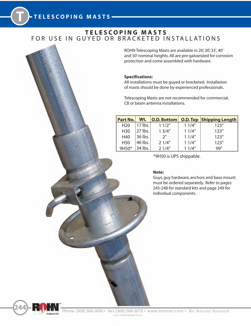
T T E L E S C O P I N G M A S T S
T E L E S C O P I N G M A S T SF O R U S E I N G U Y E D O R B R A C K E T E D I N S T A L L A T I O N S
ROHN Telescoping Masts are available in 20’, 30’, 33‘, 40’ and 50’ nominal heights. All are pre-galvanized for corrosionprotection and come assembled with hardware.
Specifications:
All installations must be guyed or bracketed. Installationof masts should be done by experienced professionals.
Telescoping Masts are not recommended for commercial, CB or beam antenna installations.
Part No.
H20H30H40H50
9H50*
Wt.
17 lbs.27 lbs.36 lbs.46 lbs.34 lbs.
O.D. Bottom
1 1/2”1 3/4”
2”2 1/4”2 1/4”
O.D. Top
1 1/4”1 1/4”1 1/4”1 1/4”1 1/4”
Shipping Length
123”123”123”123”99”
Phone (309) 566-3000 • Fax (309) 566-3079 • www.rohnnet.com • The Industry Standard© 2011 ROHN PRODUCTS LLC
244
*9H50 is UPS shippable.
Note:
Guys, guy hardware, anchors and base mountmust be ordered separately. Refer to pages 245-248 for standard kits and page 249 forindividual components.

T E L E S C O P I N G M A S T S T
Phone (309) 566-3000 • Fax (309) 566-3079 • www.rohnnet.com • The Industry Standard© 2011 ROHN PRODUCTS LLC
245
T E L E S C O P I N G M A S T S
H 2 0 | H 3 0 | H 4 0 | H 5 0 | 9 H 5 0
H20 H30 H50 9H50
NE
W
PRODUC
T9H50
UPS Shippable!
Top rings are adjustable based on antenna
mounting.
114”
231”
108”
223”
336”
102”
211”
435”
322”
96”
199”
415”
304”
527”
72”
152”
410”
233”
320”
H40

Phone (309) 566-3000 • Fax (309) 566-3079 • www.rohnnet.com • The Industry Standard
T T E L E S C O P I N G M A S T S
246© 2011 ROHN PRODUCTS LLC
I N S T A L L A T I O N G U I D E L I N E S
18’ TYP 90 TYPº
18’ TYP
120 TYPº
29’ TYP
23’ TYP
29’ TYP
23’ TYP
TOP VIEW ELEVATION VIEW TOP VIEW ELEVATION VIEW
H203WAYGUY
Actual Wire Required - 200’
H204WAYGUY
Actual Wire Required - 250’
3 Guy Wire Setup 4 Guy Wire Setup
27’ TYP 90 TYPº
27’ TYP
120 TYPº
31’ TYP
TOP VIEW ELEVATION VIEW TOP VIEW ELEVATION VIEW
H303WAYGUY
Actual Wire Required - 350’
H304WAYGUY
Actual Wire Required - 450’
3 Guy Wire Setup 4 Guy Wire Setup
H3
0 G
UY
KIT
35’ TYP
41’ TYP
31’ TYP
35’ TYP
41’ TYP
H2
0 G
UY
KIT
All Telescoping Mast kits include guys, connection hardware, anchors and ground mount.
Mast must be ordered separately.
18’ 18’
27’27’
1 618 1000’ - 6 Strand/18 GA Wire
3 GAS4303 1/2” x 30” Screw Anchor
12 61820GRPL 618/620 Gripple
1 GTMBL Ground Mount
1 618 1000’ - 6 Strand/18 GA Wire
4 GAS4303 1/2” x 30” Screw Anchor
16 61820GRPL 618/620 Gripple
1 GTMBL Ground Mount
1 618 1000’ - 6 Strand/18 GA Wire
3 GAS4303 1/2” x 30” Screw Anchor
18 61820GRPL 618/620 Gripple
1 GTMBL Ground Mount
1 618 1000’ - 6 Strand/18 GA Wire
4 GAS4303 1/2” x 30” Screw Anchor
24 61820GRPL 618/620 Gripple
1 GTMBL Ground Mount

Phone (309) 566-3000 • Fax (309) 566-3079 • www.rohnnet.com • The Industry Standard
T E L E S C O P I N G M A S T S
247© 2011 ROHN PRODUCTS LLC
TI N S T A L L A T I O N G U I D E L I N E S
36’ TYP 90 TYPº
36’ TYP
120 TYPº
39’ TYP
TOP VIEW ELEVATION VIEW TOP VIEW ELEVATION VIEW
3 Guy Wire Setup 4 Guy Wire Setup
H4
0 G
UY
KIT
43.5’ TYP 90 TYPº
43.5’ TYP
120 TYPº
47’ TYP
TOP VIEW ELEVATION VIEW TOP VIEW ELEVATION VIEW
3 Guy Wire Setup 4 Guy Wire Setup
64’ TYP
43’ TYP
47’ TYP
54’ TYP
39’ TYP
43’ TYP
47’ TYP
54’ TYP
49’ TYP
53’ TYP
58’ TYP
47’ TYP
64’ TYP
49’ TYP
53’ TYP
58’ TYP
H5
0 G
UY
KIT
H503WAYGUY
Actual Wire Required - 850’
H504WAYGUY
Actual Wire Required - 1100’
H403WAYGUY
Actual Wire Required - 550’
H404WAYGUY
Actual Wire Required - 750’
All Telescoping Mast kits include guys, connection hardware, anchors and ground mount.
Mast must be ordered separately.
36’36’
43.5’43.5’
1 618 1000’ - 6 Strand/18 GA Wire
3 GAS4303 1/2” x 30” Screw Anchor
24 61820GRPL 618/620 Gripple
1 GTMBL Ground Mount
1 618 1000’ - 6 Strand/18 GA Wire
4 GAS4303 1/2” x 30” Screw Anchor
32 61820GRPL 618/620 Gripple
1 GTMBL Ground Mount
1 618 1000’ - 6 Strand/18 GA Wire
3 GAS604 5/8” x 48” Screw Anchor
30 61820GRPL 618/620 Gripple
1 GTMBL Ground Mount
2 618 1000’ - 6 Strand/18 GA Wire
4 GAS604 5/8” x 48” Screw Anchor
40 61820GRPL 618/620 Gripple
1 GTMBL Ground Mount

I N S T A L L A T I O N G U I D E L I N E S9
H5
0 G
UY
KIT
9H503WAYGUY
Actual Wire Required - 650’
9H504WAYGUY
Actual Wire Required - 850’
All Telescoping Mast kits include guys, connection hardware, anchors and ground mount.
Mast must be ordered separately.
1 618 1000’ - 6 Strand/18 GA Wire
3 GAS604 5/8” x 48” Screw Anchor
30 61820GRPL 618/620 Gripple
1 GTMBL Ground Mount
1 618 1000’ - 6 Strand/18 GA Wire
4 GAS604 5/8” x 48” Screw Anchor
40 61820GRPL 618/620 Gripple
1 GTMBL Ground Mount
I N S T A L L A T I O N G U I D E L I N E S
1. Installation or dismantling of telescoping masts require professional contractors experienced with guyed masts.
2. All installations must be bracketed or guyed.
3. The pictured guy layouts are for a typical installation. Individual installation requirements may vary.
4. Antenna load (top load) should not exceed an effective projected area (EPA) of 2 square feet (see your antenna specifications).
33.5’ TYP 90 TYPº
33.5’ TYP
120 TYPº
36’ TYP
TOP VIEW ELEVATION VIEW TOP VIEW ELEVATION VIEW
3 Guy Wire Setup 4 Guy Wire Setup
50’ TYP
38’ TYP
41’ TYP
45’ TYP
36’ TYP
50’ TYP
38’ TYP
41’ TYP
45’ TYP
33.5’”33.5’
Phone (309) 566-3000 • Fax (309) 566-3079 • www.rohnnet.com • The Industry Standard
T T E L E S C O P I N G M A S T S
248© 2011 ROHN PRODUCTS LLC

Phone (309) 566-3000 • Fax (309) 566-3079 • www.rohnnet.com • The Industry Standard
T E L E S C O P I N G M A S T S
249© 2011 ROHN PRODUCTS LLC
TP A R T S & A C C E S S O R I E S
UNIVERSAL RIDGE MOUNTCompletely assembled for
quick and easy flat or peaked roof installation. Allows tall masts to be swung up along the ridge of
a roof.
Part No. Description
UM20 Holds masts to 1 1/2” O.D.
UM30 Holds masts to 1 3/4” O.D.
UM40 Holds masts to 2” O.D.
UM50 Holds masts to 2 1/4” O.D.
GROUND MOUNTSturdy, galvanized, drive-in type mount for all ROHN telescoping masts, 1 1/4” tubing and 1 1/2”
tubing.
Part No. Description
GTMBL Ground Mount
UNIVERSAL ROOF MOUNTFeatures galvanized finish
and heavy duty steel throughout. Completely assembled. Holds allROHN telescoping masts, 1 1/4”
tubing and 1 1/2” tubing.
Part No. Description
ETMB Universal Mount
GALVANIZED GUYSNon-tangling interconnectedcoils. Packaged 1000’ per box.
Part No. Description
618 6 strand, 18 GA
SCREW ANCHORSHot-dip galvanized screw anchor.
Part No. Description
GAS4303 1/2” dia. x 30“ long with 4” auger
GAS604 5/8” dia. x 48“ long with 6” auger
GUY CONNECTIONSUse for easy installation of 6 strand,
18 GA guys.
Part No. Description
61820GRPL Gripple Grip
Not to be used to suspend or lift personnel.
Refer to page 251 for roof mounts. Refer to page 275 for wall mounts.
Roof mounting hardware not included. Roof mounting hardware not included.

Phone (309) 566-3000 • Fax (309) 566-3079 • www.rohnnet.com • The Industry Standard© 2011 ROHN PRODUCTS LLC
250
N O T E S


Phone (309) 566-3000 • Fax (309) 566-3079 • www.rohnnet.com • The Industry Standard
R O O F M O U N T S
252
© 2011 ROHN PRODUCTS LLC
RM
E F F E C T I V E W I N D V E L O C I T Y F O R M U L A S H E E T
V = (C1) (C2) (V)e
V = E!ective Wind Velocity at centerline of antenna for calculating required ballast. eC1 = Importance factor coe#cient from Table 1.
C2 = Combined exposure and gust e!ect factor coe#cient from Table 2.
V = Design ground wind speed for location, per ANSI/TIA-222-G.
Table 1: Values of C1
I Low hazard to human life and/or damage to property, optional services provided. 1.29 0.93
II Signi$cant hazard to human life and/or damage to property, services available by other means. 1.38 1.00
III Substantial hazard to human life and/or damage to property, essential services provided. 1.48 1.07
Class Description for installing considering height, use or location 60 ft. > 60 ft.
Roof Height
Urban and suburban areas, wooded areas, or
other terrain with numerous closely spaced
obstructions having the size of single-family
dwellings or larger.
Open terrain with scattered obstructions having
heights generally less than 30’ [9.1m], including
%at, open country and grasslands.
Flat, unobstructed shorelines exposed to wind
%owing over open water, smooth mud %ats, salt
%ats, and other similar terrain.
Exposure Description of Surrounding Terrain
B
C
D
Example: 30’ antenna elevation, 90 mph design ground
wind speed, Class I, Exposure B
V = (1.29) (0.82) (90) = 95 mph
The minimum E!ective Wind Velocity for
determining ballast requirements for this
example would be 95 mph.
e
0-15 0.82 0.90 0.99
20 0.82 0.92 1.01
25 0.82 0.95 1.04
30 0.82 0.96 1.05
40 0.85 0.99 1.08
50 0.88 1.02 1.10
60 0.90 1.04 1.12
70 0.92 1.05 1.13
80 0.94 1.07 1.14
90 0.95 1.09 1.16
100 0.97 1.10 1.17
120 0.99 1.12 1.19
140 1.02 1.14 1.20
160 1.04 1.15 1.21
180 1.05 1.17 1.23
200 1.07 1.18 1.24
250 1.10 1.21 1.26
300 1.13 1.23 1.28
350 1.16 1.25 1.30
400 1.18 1.27 1.31
450 1.20 1.29 1.33
500 1.22 1.30 1.34
Antenna Centerline
Elevation AboveGround Level (ft.)
Urban orWooded
Areas
Open Country& Grasslands
Open Water or Smooth Terrain
B C D
Exposure
Table 2: Values of C2
This data sheet is provided to assist consumers in determining
the minimum E!ective Wind Velocity to be used for determining
ballast requirements from a ROHN Non-Penetrating Roof Mount
Ballast Chart. Higher velocities may be required for sites located
on hills, escarpments or ridges (refer to ANSI/TIA-222-G). Potential
increases in wind velocity due to channeling, roof projections
and other obstructions must also be considered. The information
shown should not be relied upon without competent professional
examination and veri$cation of its accuracy and suitability for a
speci$c site or application.
ROHN recommends a minimum 75 mph E!ective Wind Velocity be used for determining ballast requirements.
Refer to page 270 for ballast requirements and general notes.
<_

253Phone (309) 566-3000 • Fax (309) 566-3079 • www.rohnnet.com • The Industry Standard© 2011 ROHN PRODUCTS LLC
ROOF MOUNTS - FRM RM
F R MN O N - P E N E T R A T I N G
Mount Part No.
FRM125
FRM150
FRM166
FRM238
FRM225
FRM238SP5
MastPart No.
FY202
FY203
FY204
FY205
FY205SP
FY253
Mast Description & Height
1.25” O.D. x 16 GA. x 5.0’ (PG)
1.50” O.D. x 16 GA. x 2.5’ (PG)
1.66” O.D. x 16 GA. x 2.5’ (PG)
2.38” O.D. x 0.154“ wall x 2.5’ (HDG)
2.25” O.D. x 14 GA. x 5.0’ (HDG)
2.38” O.D. x 0.154“ wall x 5.0’ (HDG)
MAST SPECIFICATIONS
F R M B A L L A S T R E Q U I R E M E N T SEffectiveProjectedArea (EPA)
(FT )2
Ballast(LBS)
ZeroVelocity
Load(PSF)
Vs(MPH)
Vmax at centroid of projected area, (MPH)
h=2 FT h=3 FT h=4 FT h=5 FT
100200300400
100200300400
100200300400
12243648
12243648
12243648
140198242280
99140171198
81114140161
135188222269
96133157190
78108128155
110153182
219 (197)
78108129
155 (139)
6488
105127 (114)
96133
157 (154)190 (154)
6894
111134(109)
5577
91 (89)110 (89)
85119
141 (131)170 (131)
6084
99 (93)120 (93)
4968
81 (76)98 (76)
2
4
6
h = Distance from support surface to centroid of EPA.Vs = Effective wind velocity resulting in sliding on a flat surface with a .50 coefficient of friction.Vmax = Effective wind velocity based on strength or overturning.
NOTE: The velocities in ( ) apply to the FRM125 mount when the strength of the FRM125 mast governs.
3’ Square
The FRM mount is a lightweight mount and is galvanized for corrosion protection. The FRM mount is easily shipped via UPS.
Order (1) optional FRMMAT (1/8” thick) or (1) optional FRMPAD (3/8” thick) for a protective barrier between the mount and the roof. Order (1) optional SCK150safety cable kit (3/16” x 150’).
1.25” to 2.38” MastTube Diameters
2.5’ and 5’ OverallMast Heights(See Mast Descriptions)
PG = Pre-galvanized mastHDG = Hot-dip galvanized mast
16” Nominal Blocks

Phone (309) 566-3000 • Fax (309) 566-3079 • www.rohnnet.com • The Industry Standard
R O O F M O U N T S - J R M
254© 2011 ROHN PRODUCTS LLC
RM
J R MN O N - P E N E T R A T I N G
5’ Square
The JRM ships broken down on one skid and weighs approximately 50 lbs. when assembled. The JRM is galvanized for corrosionprotection. The JRM is used in cellular, PCS, broadband and other applications.
Order (1) optional JRMMAT (1/8” thick) or (1) optional JRMPAD (3/8” thick) for a protective barrier between the mount and the roof. Order (1) optional SCK150 safety cable kit (3/16” x 150’).
Refer to pages 255-256 for ballast requirements.
MountPart No.
JRM23805
JRM23855
JRM23810
JRM27505
JRM27555
JRM27510
JRM35010
Mast Description & Height
2.38” O.D. x 0.154“ wall x 5.0’ (HDG) (1 piece)
2.38” O.D. x 0.154“ wall x 10.0‘ (HDG) (2 pieces)
2.38” O.D. x 0.154“ wall x 10.0’ (HDG) (1 piece)
2.88” O.D. x 0.203“ wall x 5.0‘ (HDG) (1 piece)
2.88” O.D. x 0.203“ wall x 10.0’ (HDG) (2 pieces)
2.88” O.D. x 0.203“ wall x 10.0‘ (HDG) (1 piece)
3.50” O.D. x 0.216” wall x 10.0’ (HDG) (1 piece)
MAST SPECIFICATIONSMast
Part No.
FZ1755
FZ1753 / FZ1754
FZ1756
FZ1757
FZ1758 / FZ1759
FZ1760
FZ1761
HDG = Hot-dip galvanized mast
2.38” to 3.50” Mast Tube Diameters,1 and 2 piece options
5’ or 10’ (1 & 2 piece) Overall Mast Heights(See Mast Descriptions)
16” Nominal Blocks

255Phone (309) 566-3000 • Fax (309) 566-3079 • www.rohnnet.com • The Industry Standard
© 2011 ROHN PRODUCTS LLC
ROOF MOUNTS - JRM RM
J R M
B A L L A S T R E Q U I R E M E N T SEffectiveProjectedArea (EPA)(FT )2
Ballast(LBS)
ZeroVelocityLoad(PSF)
Vs(MPH)
Vmax at centroid of projected area, (MPH)
h=2 FT h=3 FT h=4 FT h=5 FT h=6 FT h=7 FT h=8 FT h=9 FT
250350450550650750850950105011501250
250350450550650750850950105011501250
250350450550650750850950105011501250
250350450550650750850950105011501250
250350450550650750850950105011501250
250350450550650750850950105011501250
10.014.018.022.026.030.034.038.042.046.050.0
10.014.018.022.026.030.034.038.042.046.050.0
10.014.018.022.026.030.034.038.042.046.050.0
10.014.018.022.026.030.034.038.042.046.050.0
10.014.018.022.026.030.034.038.042.046.050.0
10.014.018.022.026.030.034.038.042.046.050.0
110131148164178191204215226237247
99117133147159171182193203212221
90107121134145156166176185193202
8499112124135145154163171179187
7892105116126135144152160168175
708394104113121129136143150156
129153173191208224238252265277289
115137155171186200213225237248258
105125141156170183194205216226236
98115131145157169180190200209218
91108122135147158168178187196204
8297110121132141151159167175183
105125141156170183194205216226236
94112126140152163174184193202211
86102115128139149159168176185192
8094107118128138147155163171178
7588100111120129137145153160167
67798999107115123130137143149
91108122135147158168178187196204
8297110121132141151159167175183
7588100111120129137145153160167
698293102111120127135141148154
65768796104112119126132138144
5868778693100106113118124129
8297110121132141151159167175183
738698108118126135142150157163
67798999107115123130137143149
62738392100107114120126132138
5868778693100106113118124129
52616977838995101106111115
7588100111120129137145153160167
67798999107115123130137143149
6172829098105112119125131136
566776849198104110115121126
53627178859197103108113118
475663707682879297101105
698293102111120127135141148154
62738392100107114120126132138
566776849198104110115121126
52627077849096102107112117
4958657279859095100105109
4452596570768085899498
65768796104112119126132138144
5868778693100106113118124129
53627178859197103108113118
4958657279859095100105109
46546168747984899498102
4148556166717580848891
6172829098105112119125131136
546473818894100106112117122
5059677480869297102107111
46546268748085909499103
4351586469757984889296
3846525762677175798386
4
5
6
7
8
10
Vmax = Effective wind velocity based on strength or overturning.
h = Distance from support surface to centroid of EPA.
Vs = Effective wind velocity resulting in sliding on a flat surface with a .50 coefficient of friction.
NOTE: Mast strength may govern antenna capacity.

Phone (309) 566-3000 • Fax (309) 566-3079 • www.rohnnet.com • The Industry Standard
R O O F M O U N T S - J R M
256© 2011 ROHN PRODUCTS LLC
RM
J R M
B A L L A S T R E Q U I R E M E N T SEffectiveProjectedArea (EPA)(FT )2
Ballast(LBS)
ZeroVelocityLoad(PSF)
Vs(MPH)
Vmax at centroid of projected area, (MPH)
h=2 FT h=3 FT h=4 FT h=5 FT h=6 FT h=7 FT h=8 FT h=9 FT
250350450550650750850950105011501250
250350450550650750850950105011501250
250350450550650750850950105011501250
250350450550650750850950105011501250
250350450550650750850950105011501250
250350450550650750850950105011501250
10.014.018.022.026.030.034.038.042.046.050.0
10.014.018.022.026.030.034.038.042.046.050.0
10.014.018.022.026.030.034.038.042.046.050.0
10.014.018.022.026.030.034.038.042.046.050.0
10.014.018.022.026.030.034.038.042.046.050.0
10.014.018.022.026.030.034.038.042.046.050.0
64758695103110118124131137143
5970798895102109115121127132
556574828996102108113118124
52627077849096102107112116
4958667380869196101106110
475663707682879297101105
7588100111120129137145153160167
698293102111120127135141148154
65768796104112119126132138144
6172829098105112119125131136
5868778693100106113118124129
556574828995102107113118123
6172829098105112119125131136
566776849198104110115121126
53627178859197103108113118
5059677480869297102107111
475663707682879297101105
45536067727883889296101
53627178859197103108113118
4958657279859095100105109
46546168747984899498102
4351586469757984889296
4148556166717580848891
39465258636772
76808387
475663707682879297101105
4452596570768085899498
4148556166717580848891
3846525762677175798386
3743495459636771757882
3541475256606468717578
4351586469757984889296
4047535964697378828589
3744505560656973768083
3542475257616568727579
3339454954586165687175
3238434751555962656871
4047535964697378828589
3744495559646872767982
3541465156606467717477
3338444852566063677073
3137414650535760636669
2935394447515457606366
3744505560656973768083
3541465156606467717477
3238434852566063666972
3036414549535659626568
2934394347505356596265
2833374144485154565962
3542475257616568727579
3338444852566063677073
3036414549535659626568
2934384346505356596264
2732374044475053565861
2631353842454851535658
12
14
16
18
20
22
Vmax = Effective wind velocity based on strength or overturning.
h = Distance from support surface to centroid of EPA.
Vs = Effective wind velocity resulting in sliding on a flat surface with a .50 coefficient of friction.
NOTE: Mast strength may govern antenna capacity.

257Phone (309) 566-3000 • Fax (309)566-3079 • www.rohnnet.com • The Industry Standard© 2011 ROHN PRODUCTS LLC
ROOF MOUNTS - BRM4 RM
B RM 4N O N - P E N E T R A T I N G
Mount Part No.
BRM425
BRM430
BRM435
BRM440
BRM445
BRM455
BRM42510
BRM43510
BRM44510
Mast Part No.
KY1590
KY1592
KY1594
KY1596
KY1598
KY1600
KY2061
KY2063
KY2065
Mast Description & Height
2.38” O.D. x 0.154“ wall x 3.0’
2.88” O.D. x 0.203“ wall x 3.0‘
3.50” O.D. x 0.216“ wall x 3.0’
4.00” O.D. x 0.226“ wall x 3.0‘
4.50” O.D. x 0.237” wall x 3.0’
5.56“ O.D. x 0.258” wall x 3.0‘
2.38“ O.D. x 0.154” wall x 10.0’
3.50“ O.D. x 0.216” wall x 10.0‘
4.50” O.D. x 0.237” wall x 10.0’
MAST SPECIFICATIONS
6.5’Square
The BRM4 mount is hot-dip galvanized after fabrication for corrosion protection.
Order (1) optional BRM4MAT (1/8” thick) or (1) optional BRM4PAD (3/8” thick) for a protective barrier between the mount and the roof. Order (1) optional SCK150safety cable kit (3/16” x 150’).
Refer to pages 258-259 for ballast requirements. 2.38” to 5.56” Mast Tube Diameters
3’ and 10’ Overall Mast Heights(See Mast Descriptions)
16” Nominal Blocks
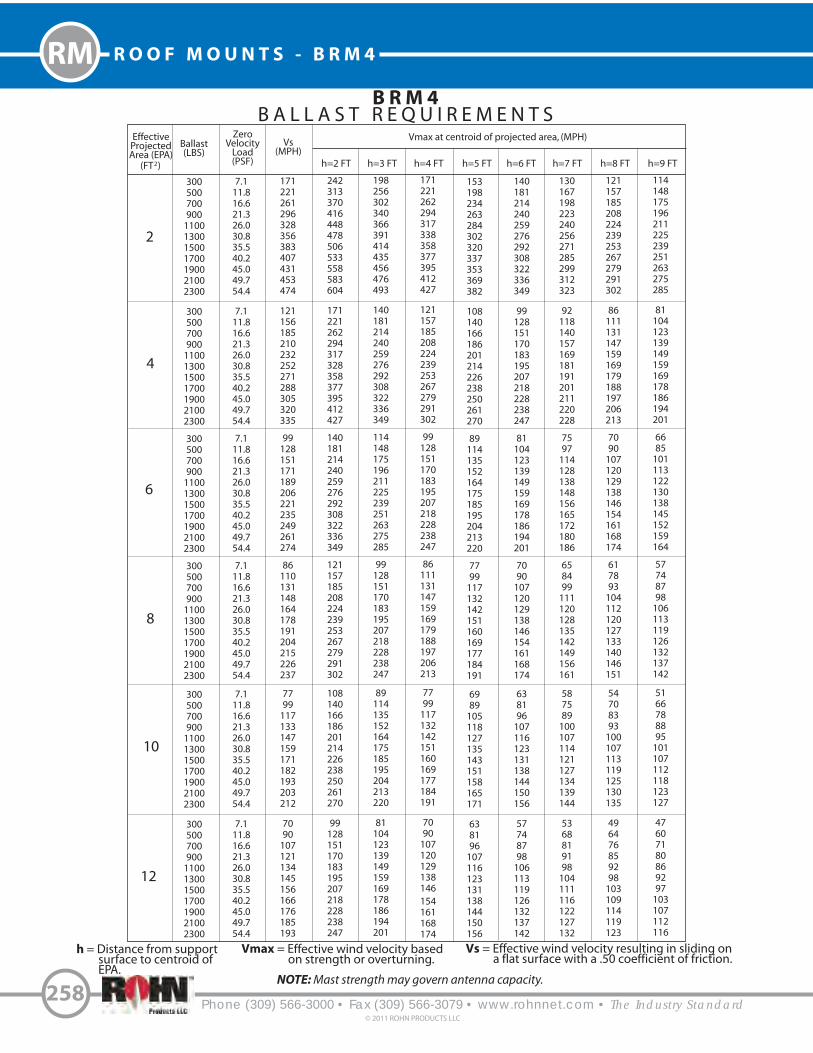
Phone (309) 566-3000 • Fax (309) 566-3079 • www.rohnnet.com • The Industry Standard
R O O F M O U N T S - B R M 4
258© 2011 ROHN PRODUCTS LLC
RM
B R M 4B A L L A S T R E Q U I R E M E N T S
EffectiveProjectedArea (EPA)(FT )2
Ballast(LBS)
ZeroVelocityLoad(PSF)
Vs(MPH)
Vmax at centroid of projected area, (MPH)
h=2 FT h=3 FT h=4 FT h=5 FT h=6 FT h=7 FT h=8 FT h=9 FT
3005007009001100130015001700190021002300
3005007009001100130015001700190021002300
3005007009001100130015001700190021002300
3005007009001100130015001700190021002300
3005007009001100130015001700190021002300
3005007009001100130015001700190021002300
7.111.816.621.326.030.835.540.245.049.754.4
7.111.816.621.326.030.835.540.245.049.754.4
7.111.816.621.326.030.835.540.245.049.754.4
7.111.816.621.326.030.835.540.245.049.754.4
7.111.816.621.326.030.835.540.245.049.754.4
7.111.816.621.326.030.835.540.245.049.754.4
171221261296328356383407431453474
121156185210232252271288305320335
99128151171189206221235249261274
86110131148164178191204215226237
7799117133147159171182193203212
7090107121134145156166176185193
242313370416448478506533558583604
171221262294317328358377395412427
140181214240259276292308322336349
121157185208224239253267279291302
108140166186201214226238250261270
99128151170183195207218228238247
198256302340366391414435456476493
140181214240259276292308322336349
114148175196211225239251263275285
99128151170183195207218228238247
89114135152164175185195204213220
81104123139149159169178186194201
171221262294317338358377395412427
121157185208224239253267279291302
99128151170183195207218228238247
86111131147159169179188197206213
7799117132142151160169177184191
7090107120129138146
154161168174
153198234263284302320337353369382
108140166186201214226238250261270
89114135152164175185195204213220
7799117132142151160169177184191
6989105118127135143151158165171
638196107116123131138144150156
140181214240259276292308322336349
99128151170183195207218228238247
81104123139149159169178186194201
7090107120129138146154161168174
638196107116123131138144150156
57748798106113119126132137142
130167198223240256271285299312323
92118140157169181191201211220228
7597114128138148156165172180186
658499111120128135142149156161
587589100107114121127134139144
5368819198104111116122127132
121157185208224239253267279291302
86111131147159169179188197206213
7090107120129138146154161168174
617893104112120127133140146151
54708393100107113119125130135
496476859298103109114119123
114148175196211225239251263275285
81104123139149159169178186194201
6685101113122130138145152159164
57748798106113119126132137142
5166788895101107112118123127
47607180869297103107112116
2
4
6
8
10
12
Vmax = Effective wind velocity based on strength or overturning.
h = Distance from support surface to centroid of EPA.
Vs = Effective wind velocity resulting in sliding on a flat surface with a .50 coefficient of friction.
NOTE: Mast strength may govern antenna capacity.

259Phone (309) 566-3000 • Fax (309) 566-3079 • www.rohnnet.com • The Industry Standard
© 2011 ROHN PRODUCTS LLC
ROOF MOUNTS - BRM4 RM
B R M 4
B A L L A S T R E Q U I R E M E N T SEffectiveProjectedArea (EPA)(FT )2
Ballast(LBS)
ZeroVelocityLoad(PSF)
Vs(MPH)
Vmax at centroid of projected area, (MPH)
h=2 FT h=3 FT h=4 FT h=5 FT h=6 FT h=7 FT h=8 FT h=9 FT
3005007009001100130015001700190021002300
3005007009001100130015001700190021002300
3005007009001100130015001700190021002300
3005007009001100130015001700190021002300
3005007009001100130015001700190021002300
3005007009001100130015001700190021002300
7.111.816.621.326.030.835.540.245.049.754.4
7.111.816.621.326.030.835.540.245.049.754.4
7.111.816.621.326.030.835.540.245.049.754.4
7.111.816.621.326.030.835.540.245.049.754.4
7.111.816.621.326.030.835.540.245.049.754.4
7.111.816.621.326.030.835.540.245.049.754.4
658499112124135145154163171179
617892105116126135144152160168
57748799109119128136144151158
54708394104113121129136143150
5267798999107115123130137143
4964758695103110118124131137
92118140157169181191201211220228
86111131147159169179188197206213
81104123139149159169178186194201
7799117132142151160169177184191
7394112126135144153161168176182
7090107120129138146154161168174
7597114128138148156165172180186
7090107120129138146154161168174
6685101113122130138145152159164
638196107116123131138144150156
607791102110118125131137143149
57748798106113119126132137142
658499111120128135142149156161
617893104112120127133140146151
57748798106113119126132137142
54708393100107113119125130135
5267798996102108114119124129
496476859298103
109114119123
587589100107114121127134139144
54708393100107113119125130135
5166788895101107112118123127
486374839096101107112117121
46607179869197102106111115
4457687682879297102106110
5368819198104111116122127132
496476859298103109114119123
47607180869297103107112116
4457687682879297102106110
425464727883889397101105
40526269758084899397101
496375849197102108113118122
46597079859096101106110114
4356667480859095100104108
41536370768186909499102
3950606772778286909497
3748576469747882869093
46597079859096101106110114
435565747985909499103107
40526269758084899397101
3849596671768084889295
3747566368727680848891
3545536065697377818487
4356667480859095100104108
40526269758084899397101
3849586570758084889295
3647556267717579838790
3444535964687276798386
3343505761656973767982
14
16
18
20
22
24
Vmax = Effective wind velocity based on strength or overturning.
h = Distance from support surface to centroid of EPA.
Vs = Effective wind velocity resulting in sliding on a flat surface with a .50 coefficient of friction.
NOTE: Mast strength may govern antenna capacity.
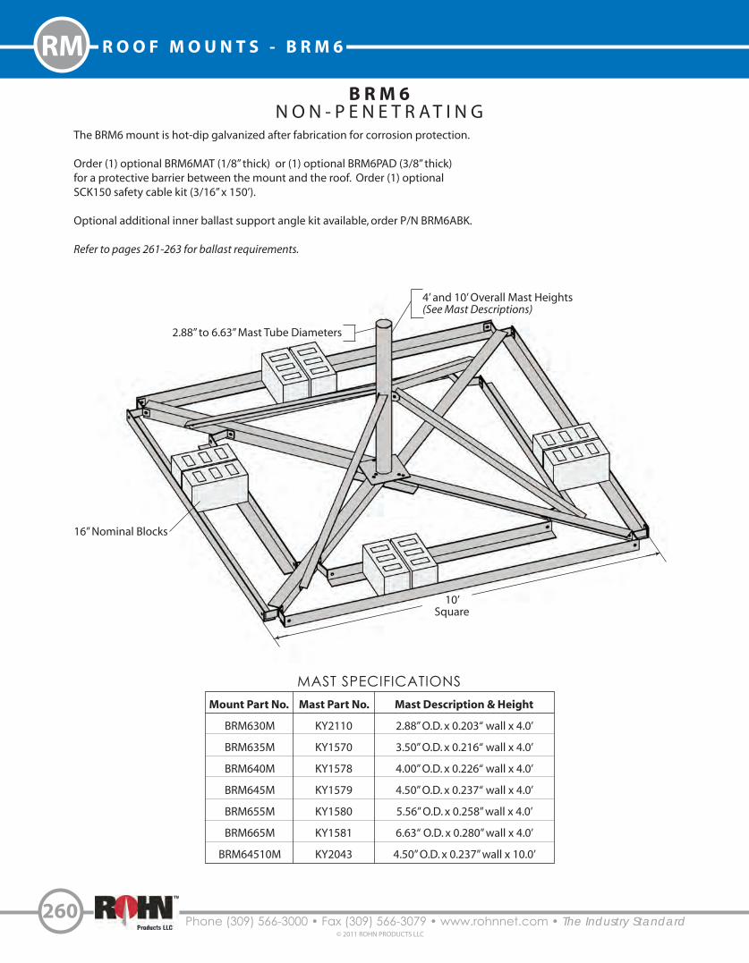
Phone (309) 566-3000 • Fax (309) 566-3079 • www.rohnnet.com • The Industry Standard
R O O F M O U N T S - B R M 6
260© 2011 ROHN PRODUCTS LLC
RM
10’Square
B R M 6N O N - P E N E T R A T I N G
Mount Part No.
BRM630M
BRM635M
BRM640M
BRM645M
BRM655M
BRM665M
BRM64510M
Mast Description & Height
2.88” O.D. x 0.203“ wall x 4.0’
3.50” O.D. x 0.216“ wall x 4.0’
4.00” O.D. x 0.226“ wall x 4.0’
4.50” O.D. x 0.237“ wall x 4.0’
5.56” O.D. x 0.258” wall x 4.0’
6.63“ O.D. x 0.280” wall x 4.0’
4.50” O.D. x 0.237” wall x 10.0’
MAST SPECIFICATIONSMast Part No.
KY2110
KY1570
KY1578
KY1579
KY1580
KY1581
KY2043
The BRM6 mount is hot-dip galvanized after fabrication for corrosion protection.
Order (1) optional BRM6MAT (1/8” thick) or (1) optional BRM6PAD (3/8” thick)for a protective barrier between the mount and the roof. Order (1) optional SCK150 safety cable kit (3/16” x 150’).
Optional additional inner ballast support angle kit available, order P/N BRM6ABK.
Refer to pages 261-263 for ballast requirements.
2.88” to 6.63” Mast Tube Diameters
4’ and 10’ Overall Mast Heights(See Mast Descriptions)
16” Nominal Blocks

261Phone (309) 566-3000 • Fax (309) 566-3079 • www.rohnnet.com • The Industry Standard
© 2011 ROHN PRODUCTS LLC
ROOF MOUNTS - BRM6 RM
B R M 6
4 F T . D I S H E L E VAT I O NB A L L A S T R E Q U I R E M E N T S
DishDiameter
Ballast(LBS)
ZeroVelocityLoad(PSF)
Design Wind Velocities(MPH)
EL=0º EL=20º EL=40º
500
750
1000
1250
1500
1750
2000
500
750
1000
1250
1500
1750
2000
2250
2500
2750
3000
750
1000
1250
1500
1750
2000
2250
2500
2750
3000
4’(1.2 m)
6’(1.8 m)
8’(2.4 m)
Vmax Vs Vmax Vs Vmax Vs
5.0
7.5
10.0
12.5
15.0
17.5
20.0
5.0
7.5
10.0
12.5
15.0
17.5
20.0
22.5
25.0
27.5
30.0
7.5
10.0
12.5
15.0
17.5
20.0
22.5
25.0
27.5
30.0
87
107
125
139
148
157
165
58
71
83
93
99
105
110
115
120
125
127
53
62
69
74
78
82
86
90
94
95
67
82
95
106
117
126
135
45
55
63
71
78
84
90
95
100
105
110
41
47
53
58
63
67
71
75
79
82
103
131
154
169
180
190
196
65
83
99
112
120
127
130
130
130
130
130
57
69
79
85
91
97
98
98
98
98
75
92
107
119
131
141
151
50
61
71
79
87
94
101
107
113
118
123
46
53
59
65
70
75
80
84
88
92
112
142
167
189
203
211
211
69
89
106
120
129
137
141
141
141
141
141
60
73
84
90
96
102
103
103
103
103
92
113
131
146
160
173
185
61
75
87
97
107
115
123
131
138
141
141
56
65
73
80
86
92
98
103
103
103
Vmax = Effective wind velocity based on strength or overturning.
EL = Dish antenna azimuth angle with horizontal.
Vs = Effective wind velocity resulting in sliding on a flat surface with a .50 coefficient of friction.
NOTE: Mast strength may govern antenna capacity.

Phone (309) 566-3000 • Fax (309) 566-3079 • www.rohnnet.com • The Industry Standard
R O O F M O U N T S - B R M 6
262© 2011 ROHN PRODUCTS LLC
RM
B R M 6
B A L L A S T R E Q U I R E M E N T SEffectiveProjectedArea (EPA)(FT )2
Ballast(LBS)
ZeroVelocityLoad(PSF)
Vs(MPH)
Vmax at centroid of projected area, (MPH)
h=4 FT h=5 FT h=6 FT h=7 FT h=8 FT h=9 FT h=10 FT
500750100012501500175020002250250027503000
500750100012501500175020002250250027503000
500750100012501500175020002250250027503000
500750100012501500175020002250250027503000
500750100012501500175020002250250027503000
500750100012501500175020002250250027503000
5.07.510.012.515.017.520.022.525.027.530.0
5.07.510.012.515.017.520.022.525.027.530.0
5.07.510.012.515.017.520.022.525.027.530.0
5.07.510.012.515.017.520.022.525.027.530.0
5.07.510.012.515.017.520.022.525.027.530.0
5.07.510.012.515.017.520.022.525.027.530.0
99121140156171185198210221232242
8199114128140151161171180189198
708699110121131140148156164171
63778899108117125133140147153
5770819099107114121128134140
536575849199106112118124129
128156180202218230242254265275280
104128147165178188198207216225228
90110128143154163171179187195198
8199114128138146153160167174177
7490104116126133140147153159161
688496108116123130136141147149
114140161180195206217227237246250
93114132147159168177185193201204
8199114128138146153160167174177
7288102114123130137144150156158
668193104113119125131137142144
61758696104110116121127132134
104128147165178188198207216225228
85104120134145154162169176183186
7490104116126133140147153159161
668193104113119125131137142144
60748595103109114120125130132
5668798895101106111
115120122
96118136152165174183192200208211
7996111125134142150157163170173
688496108116123130136141147149
61758696104110116121127132134
5668798895101106111115120122
52637382889398103107111113
90110128143154163171179187195198
7490104116126133140147153159161
647890101109115121127132138140
5770819097103108113118123125
52647482899499104108112114
4859687682879296100104106
85104120134145154162169176183186
698598110119125132138144150152
60748595103109114120125130132
546676859297102107112116118
4960697884899398102106108
45566472788286909498100
8199114128138146153160167174177
668193104113119125131137142144
5770819097103108113118123125
51637281879297101106110112
475766748084899397100102
4353616874788286899394
10
15
20
25
30
35
Vmax = Effective wind velocity based on strength or overturning.
EL = Dish antenna angle with horizontal.
Vs = Effective wind velocity resulting in sliding on a flat surface with a .50 coefficient of friction.
NOTE: Mast strength may govern antenna capacity.

263Phone (309) 566-3000 • Fax (309) 566-3079 • www.rohnnet.com • The Industry Standard
© 2011 ROHN PRODUCTS LLC
ROOF MOUNTS - BRM6 RM
B R M 6
B A L L A S T R E Q U I R E M E N T S
EffectiveProjectedArea (EPA)(FT )2
Ballast(LBS)
ZeroVelocityLoad(PSF)
Vs(MPH)
Vmax at centroid of projected area, (MPH)
h=4 FT h=5 FT h=6 FT h=7 FT h=8 FT h=9 FT h=10 FT
500750100012501500175020002250250027503000
500750100012501500175020002250250027503000
500750100012501500175020002250250027503000
5.07.510.012.515.017.520.022.525.027.530.0
5.07.510.012.515.017.520.022.525.027.530.0
5.07.510.012.515.017.520.022.525.027.530.0
49617078869299105110116121
4757667481879399104109114
445463707783889499104108
647890101109115121127132138140
60748595103109114120125130132
5770819097103108113118123125
5770819097103108113118123125
546676859297102107112116118
51637281879297101106110112
52647482899499104108112114
4960697884899398102106108
475766748084899397100102
4859687682879296100104106
45566472788286909498100
4353616874788286899394
4555647177818690949799
4352606773778185889293
4049576469737780848788
4352606773778185889293
4049576368727680838688
3847546065697276798283
4049576469737780848788
3847546065697276798283
3644515762656972757879
40
45
50
Vmax = Effective wind velocity based on strength or overturning.
EL = Dish antenna angle with horizontal.
Vs = Effective wind velocity resulting in sliding on a flat surface with a .50 coefficient of friction.
NOTE: Mast strength may govern antenna capacity.

Phone (309) 566-3000 • Fax (309) 566-3079 • www.rohnnet.com • The Industry Standard
R O O F M O U N T S - N P P K
264© 2011 ROHN PRODUCTS LLC
RM
N P P KN O N - P E N E T R A T I N G
3.4’
Mount Adjusts to Roof Angle
The NPPK mount is a great solution for broadband antennas and satellite TV dishes. The adjustable mounting plate can be center mounted or to one side as needed to accommodate other satellite TV dish mounts. Our 1LG mount (located on page 274) with a base and 1-1/4” mounting tube can be attached to the NPPK. The mount comes standard with double ballast trays on each side tohold concrete blocks. The NPPK mount is hot-dip galvanized after fabrication for corrosion protection.
Order (2) optional FRMMAT (1/8” thick) or (2) optional FRMPAD (3/8” thick) for a protective barrier between the mount and the roof. Order (1) optional SCK150 safety cable kit (3/16” x 150’).
3’
AdjustableMounting Plate
16” NominalBlocks

265Phone (309) 566-3000 • Fax (309) 566-3079 • www.rohnnet.com • The Industry Standard© 2011 ROHN PRODUCTS LLC
ROOF MOUNTS - 25GBRM RM
2 5 G B R MN O N - P E N E T R A T I N G
The 25GBRM mount is designed to support one or two 25G tower sections in a self-supporting application. The 25GBRM mount is galvanized after fabrication for corrosion protection.
Order (1) optional BRM6MAT (1/8” thick) or (1) optional BRM6PAD (3/8” thick) for a protective barrier between the mount and the roof. Order (1) optional SCK150 safety cable kit (3/16” x 150’).
Refer to page 266 for ballast requirements.
Standard 25G sections mountto top of 25GBRM
10’ Square
Overall Mast Heights(1) 25G Section - 12.4’(2) 25G Sections - 22.4’
16” Nominal Blocks

Phone (309) 566-3000 • Fax (309) 566-3079 • www.rohnnet.com • The Industry Standard
R O O F M O U N T S - 2 5 G B R M
266© 2011 ROHN PRODUCTS LLC
RM
2 5 G B R M
B A L L A S T R E Q U I R E M E N T S
EffectiveProjectedArea (EPA)(FT )2
Ballast(LBS)
ZeroVelocityLoad(PSF)
VsOne
Section(MPH)
h=12.4 FT
Vmax at centroid of projected area, (MPH)
VsTwo
Sections(MPH)
h=22.4 FT1 Sectionh=12.4 FT
2 Sectionsh=22.4 FT
500750100012501500175020002250250027503000
500750100012501500175020002250250027503000
500750100012501500175020002250250027503000
500750100012501500175020002250250027503000
500750100012501500175020002250250027503000
500750100012501500175020002250250027503000
5.07.510.012.515.017.520.022.525.027.530.0
5.07.510.012.515.017.520.022.525.027.530.0
5.07.510.012.515.017.520.022.525.027.530.0
5.07.510.012.515.017.520.022.525.027.530.0
5.07.510.012.515.017.520.022.525.027.530.0
5.07.510.012.515.017.520.022.525.027.530.0
131160185207227245250250250250250
113138159178195211225239250250250
100123142159174188201213224235246
91112129144158171183194204214224
84103119133146158169179189198207
7997112125137148158167176185193
96117135151165179191203214224234
88107124139152164175186196206215
82100115129141152163173182191200
7694108121132143153162171179187
7289102114125135145153162169177
698497109119128137146154161168
111136157176190201211221231240244
92112130145157166174182190198201
8098113126136144152159166172175
7288101113122129136142149154157
668093104112118124130136141144
61748696104110115121126131133
658092103111118124130135140143
5770819198104109114119124126
52637382889498103107112113
485867758186909599103104
4454637076808488929597
425159667175
7983869091
2
4
6
8
10
12
EffectiveProjectedArea (EPA)(FT )2
Ballast(LBS)
ZeroVelocityLoad(PSF)
VsOne
Section(MPH)
h=12.4 FT
Vmax at centroid of projected area, (MPH)
VsTwo
Sections(MPH)
h=22.4 FT1 Sectionh=12.4 FT
2 Sectionsh=22.4 FT
500750100012501500175020002250250027503000
500750100012501500175020002250250027503000
500750100012501500175020002250250027503000
5.07.510.012.515.017.520.022.525.027.530.0
5.07.510.012.515.017.520.022.525.027.530.0
5.07.510.012.515.017.520.022.525.027.530.0
7491105117129139149158166174182
7086100111122132141149157165172
678295106116126134142150157164
668093104114123131139147154161
63778999109118126133141147154
60748696105113121128135142148
5770809097103108113118123125
546676859297102107111116118
51627281879297101106110112
3948566267717578818586
3746535964677174778082
3644505661646871747778
14
16
18
h = Distance from support surface to centroid of EPA.Vs = Effective wind velocity resulting in sliding on a flat surface with a .50 coefficient of friction.Vmax = Effective wind velocity based on strength or overturning.

267Phone (309) 566-3000 • Fax (309) 566-3079 • www.rohnnet.com • The Industry Standard© 2011 ROHN PRODUCTS LLC
ROOF MOUNTS - AAGM RM
A A G MN O N - P E N E T R A T I N G
Mount Part No.
AAGM35
AAGM40
AAGM45
AAGM55
AAGM6560
Mast Part No.
FYS75
FYS76
FYS77
FYS78
FYS96
Mast Description & Height
3.50” O.D. x 0.216” wall x 4.5’
4.00” O.D. x 0.226” wall x 4.5’
4.50” O.D. x 0.237 wall x 4.5’
5.56” O.D. x 0.258” wall x 4.5’
6.63” O.D. x 0.280” wall x 5.0’
MAST SPECIFICATIONS
16.3’
14.3’
The AAGM mount is capable of supporting dishes with diameters up to 10 feet. The AAGM mount is hot-dip galvanized after fabrication for corrosion protection.
Order (1) optional AGMMAT (1/8” thick) or (1) optional AGMPAD (3/8” thick) for a protective barrier between the mount and the roof. Order (1) optional SCK150 safety cable kit (3/16” x 150’).
Refer to page 268 for ballast requirements.
3.50” to 6.63” Mast Tube Diameters2.5’ and 5’ Overall Mast Heights(See Mast Descriptions)
16” Nominal Blocks

Phone (309) 566-3000 • Fax (309) 566-3079 • www.rohnnet.com • The Industry Standard
R O O F M O U N T S - A A G M
268© 2011 ROHN PRODUCTS LLC
RM
A A G M
4 . 5 F T D I S H E L E VAT I O NB A L L A S T R E Q U I R E M E N T S
DishDiameter
Ballast(LBS)
ZeroVelocityLoad(PSF)
Vmax(MPH)
Vs (MPH)
EL=0º EL=20º EL=40º
1000
1500
2000
2500
3000
3500
4000
5000
6000
1000
1500
2000
2500
3000
3500
4000
5000
6000
1000
1500
2000
2500
3000
3500
4000
5000
6000
1000
1500
2000
2500
3000
3500
4000
5000
6000
4’(1.2 m)
6’(1.8 m)
8’(2.4 m)
10’(3.0 m)
6.0
9.0
12.0
15.1
18.1
21.1
24.1
30.1
36.1
6.0
9.0
12.0
15.1
18.1
21.1
24.1
30.1
36.1
6.0
9.0
12.0
15.1
18.1
21.1
24.1
30.1
36.1
6.0
9.0
12.0
15.1
18.1
21.1
24.1
30.1
36.1
135
164
187
207
225
240
250
250
250
90
109
125
138
150
160
165
165
165
68
82
94
104
112
120
125
125
125
46
56
64
71
77
82
85
85
85
91
111
128
143
157
170
181
203
222
60
74
85
96
105
113
121
135
148
45
56
64
72
79
85
91
101
111
31
38
44
49
54
58
62
69
76
93
114
132
147
161
174
186
208
228
62
76
88
98
108
116
124
139
152
47
57
66
74
81
87
93
104
114
33
40
46
52
57
61
65
73
80
101
123
142
159
174
188
201
225
246
67
82
95
106
116
125
134
150
164
50
62
71
79
87
94
101
112
123
40
49
57
64
70
75
80
85
85
Vmax = Effective wind velocity based on strength or overturning.
EL = Dish antenna azimuth angle with horizontal.
Vs = Effective wind velocity resulting in sliding on a flat surface with a .50 coefficient of friction.
NOTE: Mast strength may govern antenna capacity.

269Phone (309) 566-3000 • Fax (309) 566-3079 • www.rohnnet.com • The Industry Standard© 2011 ROHN PRODUCTS LLC
ROOF MOUNTS - PRM6 RM
P R M 6N O N - P E N E T R A T I N G
Mount Part No.
PRM635
PRM640
PRM645
PRM655
Mast Description
3.50” O.D. x 0.216“ wall
4.00” O.D. x 0.226“ wall
4.50” O.D. x 0.237“ wall
5.50” O.D. x 0.258” wall
MAST SPECIFICATIONSMast Part No.
KY1672
KY1673
KY1674
KY1675
2.4’
10.4 ’
DishDiameter
Ballast(LBS)
ZeroVelocity
Load(PSF)
Design Wind Velocities(MPH)
EL=0º EL=20º EL=40º
16001800200022002400
160018002000220024002600280030003200340036003800
4’(1.2 m)
6’(1.8 m)
Vmax Vs Vmax Vs Vmax Vs17.219.421.523.725.8
17.219.421.523.725.828.030.132.334.436.638.740.9
145154162168171
97102108112114116118120122124125125
122130137144150
81869196
100104108112115119122125
180184187189189
117123125126126126126126126126126126
137146154161168
9197
102107112117121125126126126126
198198198198198
126132132132132132132132132132132132
168179188197198
112119125131132132132132132132132132
BALLAST REQUIREMENTS
The PRM6 mount is capable of supporting dishes with diameters up to 6 feet. The mount is hot-dip galvanized after fabrication forcorrosion protection. Th PRM6 mount is also UPS shippable.
Order (1) optional PRM6MAT (1/8” thick) or (1) optional PRM6PAD (3/8” thick) for a protective barrier between the mount and the roof. Order (1) optional SCK150 safety cable kit (3/16” x 150’).
Vmax = Effective wind velocity based on strength or overturning.
EL = Dish antenna azimuth angle with horizontal.
Vs = Effective wind velocity resulting in sliding on a flat surface with a .50 coefficient of friction.
NOTE: Mast strength may govern antenna capacity.
Concrete blocks notprovided with mount.
Post Tensioning Rods (TYP)
3.50” to 5.50” Mast Tube Diameters 5.0’ Overall Mast Heights(See Mast Descriptions)

Phone (309) 566-3000 • Fax (309) 566-3079 • www.rohnnet.com • The Industry Standard
R O O F M O U N T S
270
© 2011 ROHN PRODUCTS LLC
RM
B A L L A S T R E Q U I R E M E N T S F O R R O O F M O U N T S
1. Ballast requirements are provided to assist consumers in determining the applicability of a non-penetrating roof mount for an antenna installation and to assist in determining the amount of ballast required. The ballast requirements should not be relied upon without competent local professional examination and verification of its accuracy and suitability for a specific site or application.
2. Specific antennas and/or other mounting configurations may require more stringent strength and ballast requirements and must be investigated for each installation. The load carrying requirements of the supporting surface, the mount and mast, the antenna and the antenna’s connection to the mast must be investigated for each installation.
3. When antenna areas are indicated vs. specific antenna types, the areas tabulated are effective projected areas that include appropriate wind drag factors applied to the projected areas of the supported antennas and the exposed portions of the mount and ballast. The center of the effective projected area is assumed to be at the top of the mounting pipe or the height indicated in the ballast table. Unless otherwise indicated, tabulated ballast requirements assume that the effective projected areas are concentric to the mount and that uplift or download wind forces are insignificant.
4. The tabulated wind velocities are considered to occur at the centroid of the effective projected areas. The wind velocity appropriate for an installation must be determined on an individual site basis considering the location and elevation of the mount. The wind velocity at ground level must be multiplied by appropriate height escalation and gust factors. Potential increases in wind velocity due to channeling, roof projections, and other obstructions, must also be considered when determining ballast requirements.
5. The ballast weights indicated are assumed to be uniformly distributed on the mount. The weight of the mount and antenna may be considered as ballast. Mounts are assumed to be mounted on a flat supporting surface.
6. The zero velocity loads shown are equal to the tabulated ballast weights divided by the total area enclosed by the perimeter of the mount. This area is greater than the ballast contact area. Loads which must be investigated include reactions caused by wind forces and moments, live loads, ice loads, earthquake loads and the dead loads of ballast, mount, antenna, mounting hardware, miscellaneous equipment and roof pads.
7. The tabulated maximum wind velocities (Vmax) are based on a minimum 1.5 factor of safety against structural failure and overturning.
8. The tabulated wind velocities resulting in sliding (Vs) are based on a factor of safety equal to 1.0 and an effective coefficient of friction equal to 0.50 between the mount and a flat supporting surface. A 1.0 factor of safety was used assuming that at higher wind velocities, safety cables or other suitable attachments to the support structure would prevent sliding beyond a safe, designated area.
9. The appropriate coefficient of friction and factor of safety to determine wind velocities resulting in sliding must be determined on an individual site basis. The coefficient of friction may vary under changing moisture and temperature conditions. The minimum coefficient of friction must be used to evaluate sliding resistance. Wind speeds resulting in sliding for other factors of safety or for other coefficients of friction may be found by multiplying the tabulated values of Vs by the following modification factor:
Modification Factor = [µ /(.5 x FS)]1/2
µ= Coefficient of Friction FS = Factor of Safety
10. The values of Vs indicated do not apply for installations which are prevented from sliding by cables or other suitable attachments to the supporting structure.
11. Roof pads are recommended to prevent damage to roof membranes. Pads should be placed under all contact areas.
12. ROHN recommends that ballast material always be placed prior to mounting the antenna and that roof pads and mount be secured to prevent hazards from occurring under extreme wind loading conditions. Precautions should also be taken to prevent the inadvertent removal of ballast material after installation and to insure that all ballast material is fully supported by the mount (required for ballast to be effective in resisting overturning and sliding).
13. When adhesives are used to secure roof pads, the adhesive must be compatible with the supporting surface. Precautions should be taken to insure that damage to the supporting surface will not occur upon wind loading.
14. The installation, roof material and supporting structure must be capable of withstanding all loads imposed by the antenna system. Supporting surfaces, anchors and/or safety cables must be sufficient to resist the reactions from the antenna system. The installation must meet all applicable local, state and federal requirements.

271Phone (309) 566-3000 • Fax (309) 566-3079 • www.rohnnet.com • The Industry Standard
© 2011 ROHN PRODUCTS LLC
ROOF MOUNTS - URM RM
U R M
Features: 1. URM mount can be used on a flat roof, sloped roof or over a roof peak. 2. URM mount can be used with 2.88” to 4.50” O.D. masts (order separately). 3. Bottom of mount pivots to match roof pitch. 4. Rear leg adjusts for extra length. 5. Mount base angles are pre-drilled to accept 1/2” diameter connectors.
Optional Masts - Ordered Separately
P2530 2.88” O.D. x 0.203“ wall x 30” Long
P330 3.50” O.D. x 0.216“ wall x 30” Long
P3530 4.00” O.D. x 0.226“ wall x 30” Long
P430 4.50” O.D. x 0.237“ wall x 30” Long
16”
24” 28”
25”
ROHN’s Universal Roof Mount (URM) is capable of supporting most PCS, Cellular, and Microwave antennas. The URM adapts to
various roof pitches and the fully adjustable rear-leg allows for use on a !at or up to a 12”/12” pitched roof. Installation is easy
because of the quick adaptability, plus there’s no need for concrete blocks. The URM is hot-dip galvanized after fabrication for
corrosion protection, and can easily ship UPS.
Braces provided with
multiple holes to allow
+ / - 26” of length
adjustment.

Phone (309) 566-3000 • Fax (309) 566-3079 • www.rohnnet.com • The Industry Standard
R O O F M O U N T S - S H R M
272© 2011 ROHN PRODUCTS LLC
RM
S H R M
26”28”
24”
16”
Features:
1. SHRM mount can be used on a flat roof or on a roof peak, up to 45 degrees maximum pitch.
2. SHRM mount can be used with 2.88” to 5.00” O.D. masts (ordered separately).
3. Bottom of mount pivots to match roof pitch.
4. Mount base angles are pre-drilled to accept 1/2” diameter connectors.
ROHN’s Saw Horse Roof Mount (SHRM) is capable of supporting most PCS, Cellular, and Microwave antennas. The SHRM
allows for placement of antennas on !at roofs or roof peaks with up to a 12”/12” pitch. The SHRM is also able to be installed on
!at roofs. Installation is easy because of the quick adaptability, plus there’s no need for concrete blocks. The SHRM is hot-dip
galvanized after fabrication for corrosion protection, and can easily ship UPS.
Optional Masts - Ordered Separately
P2530 2.88” O.D. x 0.203“ wall x 30” Long
P330 3.50” O.D. x 0.216“ wall x 30” Long
P3530 4.00” O.D. x 0.226“ wall x 30” Long
P430 4.50” O.D. x 0.237“ wall x 30” Long
28”

273Phone (309) 566-3000 • Fax (309) 566-3079 • www.rohnnet.com • The Industry Standard
© 2011 ROHN PRODUCTS LLC
ROOF MOUNTS - TRT RM
T R T 3 6 / T R T 6 0 / T R T A G 2
Description
3’ tall, tube legs (PG)
5’ tall, tube legs (PG)
5’ tall, angle legs (HDG)with 2.38” O.D. x 0.154“ wall x 3.5’ long mast (HDG)
SPECIFICATIONS
Part No.
TRT36
TRT60
TRTAG2
TRT60
The TRT is a Tripod Roof Tower, which comes fully assembled and snaps out into position for quick installation using up to 1/4” dia. connectors.
The TRTAG2 mount comes with a 2 3/8” O.D. hot-dip galvanized mast, the TRT36 and TRT60 mounts accept masts up to 1 3/4” O.D. (ordered
separately). The bolt-on swivel feet adjust to most any pitch roof. TRT mounts are galvanized for corrosion protection. All TRT mounts are
UPS shippable.
TRTAG2
TRT36
Angle leg
Tube leg
TRTAG2 comes with a 2 3/8” O.D. mast.
Masts must be ordered separately for
the TRT36 and TRT60.
Please see page 301 for mast options.
TRT36 and TRT60 "t ROHN’s
Telescoping masts
(see pages 244-249).
PG = Pre-galvanizedHDG = Hot-dip galvanized
Mast

Phone (309) 566-3000 • Fax (309) 566-3079 • www.rohnnet.com • The Industry Standard© 2011 ROHN PRODUCTS LLC
274
N O T E S


1 L G
Phone (309) 566-3000 • Fax (309) 566-3079 • www.rohnnet.com • The Industry Standard
W A L L M O U N T S - 1 L G
276
© 2011 ROHN PRODUCTS LLC
WM
The Universal One-Legged Mount (1LG) may be the one and only mount that can be installed on any part of any building. This
mount is designed for many types of antennas – home, TV, MMDS, DBS and more. The mount has a 1-1/4” O.D. mounting pipe
and includes (4) 1/4” dia. x 2” long lag screws for installation. The mount is galvanized for corrosion protection and goes together
quickly. The mount is easily shipped via UPS.
7”
12”
115o
1.25” O.D. x 16GA
Mounting Tube

277Phone (309) 566-3000 • Fax (309) 566-3079 • www.rohnnet.com • The Industry Standard
© 2011 ROHN PRODUCTS LLC
P W M
WALL MOUNTS - PWM
36”
WM
The ROHN Pole Wall Mount (PWM) is designed to support most Satellite, PCS, Cellular, and Microwave antennas. The PWM
allows you to vary the mounting pipe length and diameter, accepting 2 7/8” O.D. - 5“ O.D. mounting tubes. The PWM is
hot-dip galvanized after fabrication for corrosion protection, and can easily be shipped UPS.
Adjustable mast o!set
from wall at 16”, 22” and 28”
Optional inside mounting angles,
ordered separately.
P/N: FY77(2) required
for mounting inside
Optional hardwaremounting kit
P/N: HMK18MIncludes: (4) 1/2” dia. x 18”threaded rods and sealant.
32”

W M 4
Single: Wall ClearanceWM6S 6“ clearanceWM8S 8” clearanceWM12S 12“ clearanceWM18S 18” clearanceWM24S 24“ clearance
Double: Wall ClearanceWM8D 8” clearanceWM12D 12“ clearanceWM18D 18” clearanceWM24D 24“ clearance
Phone (309) 566-3000 • Fax (309) 566-3079 • www.rohnnet.com • The Industry Standard
W A L L M O U N T S
278© 2011 ROHN PRODUCTS LLC
WM
WM212
Single and double extended wall mount assemblies can be used on masonry, wood, metal,
and other types of walls using up to 1/4” dia. lag screws or bolts. The Wall Mounts are
versatile, coming in a variety of stand o! lengths and supporting 7/8” to 2 3/4“ O.D. masts.
The mounts are available as single brackets or double brackets. Masts are held in place with
a unique “Anti-Twist” locking clamp. Galvanized for durability, these Wall Mounts are UPS shippable.
Clamp Accepts 7/8” to 2 3/4” O.D.Mast Tube Diameters, mastordered separately.
WMB12AOptional diagonalstrap kit, ordered
separately.
Anti-Twist Locking Screw
W M 2 1 2
The WM212 mount provides 12” clearance to the wall. The WM212 is hot-dip
galvanized for corrosion protection. Optional WMB12A diagonal is available
to provide extra strength. Mount is pre-drilled to accept 1/2” dia. connectors.
E X T E N D E D W A L L M O U N T A S S E M B L I E S
2 3/8” O.D. x 0.154” wall x 6’ longMounting Tube, provided
with mount.
WM4
Single: Upper Bracket only
Double: Upperand Lower Bracket
Clamp Accepts 7/8” to 2 3/4” O.D.Mast Tube Diameters, mast
ordered separately.
Anti-Twist Locking Screw
2.38” O.D. x 0.154” wall
NOTE: Connectors to wall not included.
See page 301 for Mast options.
The WM4 mount provides 3” clearance to the wall. The WM4 is hot-dip galvanized
for corrosion protection. Masts are held in place with a unique “Anti-Twist” locking
clamp. This mount includes (4) 1/4” dia. x 2” long lag screws for mounting.

279Phone (309) 566-3000 • Fax (309) 566-3079 • www.rohnnet.com • The Industry Standard
© 2011 ROHN PRODUCTS LLC
G-SERIES WALL MOUNTS WM
H B U T V R O
The HBUTVRO provides lateral support for 25G, 45G and 55G
bracketed towers.
The bracket is pre-drilled to accept 5/8” dia.
connectors to wall at 16“ or 24” spacing.
Adjustable to position tower 18” - 36” from wall.
The 25GWM upper bracket provides lateral support for 25G wall supported
towers. The lower bracket provides both lateral and vertical support. The 25G
base plate (P/N KH6775, not shown) is provided with mount to provide an
adjustable 6” - 20” of clearance to wall.
The brackets are pre-drilled to accept 5/8” dia. connectors at 16” or 24”
spacing. A minimum 5’ separation between the top and bottom brackets
is recommended.
K H 1 0 1 4
F O R 6 5 G B R A C K E T E D T OW E R S
The KH1014 bracket provides lateral support for 65G
bracketed towers.
The brackets are pre-drilled to accept 3/4” dia. connectors
to wall at various center-to-center spacings (4.75“ increments).
Adjustable to position tower 18” - 30” from wall.
G - S E R I E S W A L L B R A C K E T S & B A S E M O U N T S
2 5 G W M
F O R 2 5 G WA L L S U P P O R T E D T OW E R S
All mounts shown are hot-dip galvanized.
60”
27”
74”
60”

Phone (309) 566-3000 • Fax (309) 566-3079 • www.rohnnet.com • The Industry Standard© 2011 ROHN PRODUCTS LLC
280
N O T E S


Phone (309) 566-3000 • Fax (309) 566-3079 • www.rohnnet.com • The Industry Standard
M T O W E R M O D I F I C A T I O N M A T E R I A L - G U Y E D T O W E R S
282© 2011 ROHN PRODUCTS LLC
Item
1
2
3
4
5
Qty.
3
3
6
9
3
Part No.
KC144
KC465
210050GA
210059GA
KC441
Description
Bar Flat Bracket Guy .38 x 5 x 4.5’
Bar Flat TA .38 x 3.5 x1.83’
Bolt Assembly 3/4 x 2-3/4 HSB A325
Bolt Assembly 3/4 x 5-1/2 HSB A325
Spacer Bracket Guy .63 x 3.13 x 4.5”5
GA85 Bill of Material
R O H N M O D E L 8 0 G U Y E D T O W E RS TA N D A R D G U Y B R A C K E T S F O R 8 3 & 8 4 S E C T I O N S
( 2 3 / 8 ” & 2 7 / 8 ” O . D . L E G S )
Item
1
2
3
4
Qty.
3
3
6
9
Part No.
KC143
KC145
210047GA
210058GA
Description
Bar Flat Bracket Guy .38 x 4.5 x4.5’
Bar Flat TA 2.75 x .38 x 1.82’
Bolt Assembly 3/4 x 2 HSB A325
Bolt Assembly 3/4 x 5 HSB A325
Torque Bar Shown
1
23
4
Tower Brace (REF)
These guy brackets are designed for 5/8” EHS maximum guys at 80% guy radius. For use on ROHN Model 80 tower only, supported on brace clips.
For single braced standard sections, guy bracket must be used at the top of the section.
For double braced standard sections, guy brackets may be used at any panelpoint.
GA80 Bill of Material
*
Torque Bar Shown
1
23
4
Tower Brace (REF)
*
5
These guy brackets are designed for 5/8” EHS maximum guys at 80% guy radius. For use on ROHN Model 80 tower only.
For single braced standard sections, guy bracket must be used at the top of the section.
For double braced standard sections, guy brackets may be used at any panelpoint.
R O H N M O D E L 8 0 G U Y E D T O W E RS TA N D A R D G U Y B R A C K E T S F O R 8 5 S E C T I O N S
( 3 1 / 2 ” O . D . L E G S )

Phone (309) 566-3000 • Fax (309) 566-3079 • www.rohnnet.com • The Industry Standard
T O W E R M O D I F I C A T I O N M A T E R I A L - G U Y E D T O W E R S
283© 2011 ROHN PRODUCTS LLC
MT O R Q U E A R M
C H A N N E L A S S E M B LY F O R 8 0 T OW E R S
NOTE: For single braced sections, torque arm must bear on brace clips above flange plates. For double braced sections,
torque arm must bear on brace clips at any panel point.
Tower
Leg Clamp
Bolt Assembly withBeveled Washers
Equalizer PlateTower Leg
Bolt Assembly
Bottom Plate
Bolt Assembly withBeveled Washers
Available Sizes:
nnel (C10x15.3)
To order, provide leg size and desired channel size.

Phone (309) 566-3000 • Fax (309) 566-3079 • www.rohnnet.com • The Industry Standard
T O W E R M O D I F I C A T I O N M A T E R I A L - G U Y E D T O W E R S
©2011 ROHN PRODUCTS LLC
M
284
R E I N F O R C E M E N T S F O R 8 0 S E R I E S T O W E R SS TA N D A R D PA R T S AVA I L A B L E F O R T OW E R M O D I F I C AT I O N S
A N D F I E L D R E I N F O R C EM E N T
Detail of bolt-on midspan horizontal brace.
Detail of horizontal girt.
Added braces are shown as a bold line.
To order, provide leg size and size of horizontal desired.

Phone (309) 566-3000 • Fax (309) 566-3079 • www.rohnnet.com • The Industry Standard
T O W E R M O D I F I C A T I O N M A T E R I A L - G U Y E D T O W E R S
© 2011 ROHN PRODUCTS LLC
M
285
R E I N F O R C E M E N T S F O R 8 0 S E R I E S T O W E R SS TA N D A R D PA R T S AVA I L A B L E F O R T OW E R M O D I F I C AT I O N S
A N D F I E L D R E I N F O R C EM E N T
For 80 Series towers
For 80/90 Series towers
Detail of bolt-on lug.
Detail of bolt-on midspan horizontal bracket.
Added braces are shown as a bold line.
Standard and Heavy Duty replacement braces areavailable. To order heavy duty braces, specify leg size
and desired brace size.
Lug P/N (1)
KB299
KB299SP
KB489
KB489SP
KB489SP1
KB492
U-Bolt Assy. (4)
JR83A
JR84A
JR84A
JR88A
JR89A
JR88A
X-Brace Lug Requirements (Pipe)
Leg O.D.
2.38
2.38
2.88
2.88
2.88
3.50
Assy. P/N
KB497A
KB497ASP
KB498A
KB498ASP
KB498ASP1
KB499A
Lug P/N (1)
KB555
KB556
KB557
KB558
KB559
U-Bolt Assy. (4)
JR83A
JR83A
JR84A
JR84A
JR88A
X-Brace Lug Requirements (Solid Rod)
Leg O.D.
2.25
2.50
2.75
3.00
3.25
Assy. P/N
KB565A
KB566A
KB567A
KB568A
KB569A
Bracing (16 GA)
Part No.
KB35R
KB36R
210018GA
Description
1.50” Tube, 16GA Diagonal
1.50” Tube, 16GA Horizontal
1/2 x 1-1/2 A325 Bolt Assy.
Bracing (11 GA)
Part No.
KB37R
KB38R
210019GA
Description
1.50” Tube, 11GA Diagonal
1.50” Tube, 11GA Horizontal
1/2 x 1-3/4 A325 Bolt Assy.
Detail of bolt-on horizontal brace.
Standard Bracing Available
Similar reinforcements available for 90 series towers.

Girt SupportBracket
Tower Leg(Ref )
1/2” LegU-bolt
Diagonal TowerBraces
BoltAssembly
Center Plate
Horizontal Girt(Typ)
S E L F - S U P P O R T I N G R E I N F O R C E M E N T S
S T A N D A R D P A R T S A V A I L A B L E F O R T O W E R M O D I F I C A T I O N S
A N D F I E L D R E I N F O R C E M E N T
Bolt on brackets are available for all SSV towers.
Girt Support Bracket
1/2” LegU-Bolt
BoltAssemblies
Diagonal TowerBraces (Ref )
Center Plate
Horizontal Girt (Typ)
VIEW A-A
Phone (309) 566-3000 • Fax (309) 566-3079 • www.rohnnet.com • The Industry Standard
TOWER MODIFICATION MATERIAL - SELF-SUPPORTING TOWERS
286
© 2011 ROHN PRODUCTS LLC
M
Added horizontalgirt to increase leg
capacity (TYP)

U-bolt Connection(Typical)
Added redundants toincrease brace and legcapacity (TYP)
S S M W S E L F - S U P P O R T I N G R E I N F O R C E M E N T S
S T A N D A R D P A R T S A V A I L A B L E F O R T O W E R M O D I F I C A T I O N S
A N D F I E L D R E I N F O R C E M E N T
TOWER MODIFICATION MATERIAL - SELF-SUPPORTING TOWERS
Phone (309) 566-3000 • Fax (309) 566-3079 • www.rohnnet.com • The Industry Standard© 2011 ROHN PRODUCTS LLC
287
M
INTERNAL TOWER VIEW(Hip Bracing)
Bolt-on brackets are available for allSSMW legs and internal braces.

Phone (309) 566-3000 • Fax (309) 566-3079 • www.rohnnet.com • The Industry Standard
T O W E R M O D I F I C A T I O N M A T E R I A L
288© 2011 ROHN PRODUCTS LLC
M
SIZE & TYPEULTIMATESTRENGTH(LBS)
SIZEULTIMATESTRENGTH(LBS)
3/16EHS
1/4EHS
5/16EHS
3/8EHS
7/16EHS
1/2EHS
9/16EHS
5/8EHS
3/4EHS
3990
6650
11200
15400
20800
26900
35000
42400
58300
6000
11000
17500
17500
26000
36000
36000
50000
76000
GAR
GAR
GAR
GAR
GAC34
GAC34
GAC34
GAC34
GAC56
GAC56
GAC56
GAC56
GAC56
GAC57
GAC57
GAC57
GAC57 GAC58
GAC58
GAC59
GAC59
G U Y A N C H O R S E L E C T I O N C H A R T
ANCHOR RODS COMPATIBLE WITH TURNBUCKLE SIZE
ANCHOR RODS
Part No.
GAR30
GAC303
GAC305
GAC3455TOP
GAC5655TOP
GAC5755TOP
GAC5855TOP
GAC5955TOP
L
84”
84”
84”
84”
120”
168”
192”
240”
A
1”
2”
2”
2”
2-1/2”
3”
4”
4”
B
-
-
-
12”
12”
12”
12”
18”
C
2”
1”
1”
1”
1-1/4”
1-3/8”
1-3/4”
1-3/4”
D
5/8”
5/8”
5/8”
3/4”
1-1/4”
1-7/16”
1-1/4”
1-7/16”
T
-
3/16”
3/16”
3/8”
1/2“
3/4”
1”
1”
Weight (lbs.)
9
13
14
25
65
125
220
310
Type
GAR
GAC
GAC
GAC34
GAC56
GAC57
GAC58
GAC59
GAC303(3) 9/16” HOLES
GAC305(5) 9/16” HOLES
A A
T T
A
5-1/4"
C
LL L
GAR30
GAC3455TOP(5) 11/16” HOLES
GAC5655TOP(5) 13/16” HOLES
GAC5755TOP(5) 15/16” HOLES
GAC5855TOP(5) 1-3/16” HOLES
GAC5955TOP(5)1-3/16” HOLES
A
L
5-1/4"
(2) 3/16”plates, one
on eachside
D DD D
B B
GAR30Anchor
Rod
C
3/4” dia.bolt
included
C C
NOTE: GAC Anchors require use of eye and eye turnbuckles. All other anchors are for use with eye and jaw turnbuckles. Refer to page 297.
3/8
1/2
5/8
5/8
3/4
7/8
7/8
1
1-1/4
GAC
GAC
GAC
1/2” dia.bolts
provided
GUYS TURNBUCKLES


N U T S , B O LT S & W A S H E R S
Phone (309) 566-3000 • Fax (309) 566-3079 • www.rohnnet.com • The Industry Standard
H A R D W A R E
290© 2011 ROHN PRODUCTS LLC
H
Dia. x Length (inches)
5/16 x 2-3/8
3/8 x 1-1/4
3/8 x 1-1/2
3/8 x 2
3/8 x 2-1/2
3/8 x 2-1/2 (Full Thread)
3/8 x 4
3/8 x 4 (Full Thread)
7/16 x 2-1/2
5/8 x 1-3/4
5/8 x 2
5/8 x 3-1/4
5/8 x 3-3/4
3/4 x 4-1/2
7/8 x 3
Assembly Part No.
210003GA
210005GA
210008GA
210009GA
210011GA
210176GA
210014GA
210013GA
210016GA
210146GA
210140GA
210036GA
210038GA
210091GA
210062GA
GRADE 5 BOLT ASSEMBLIES, GALVANIZED[HEX BOLTS, NUT & LOCKING DEVICE]
Full Thread
Pal nuts included with assembly P/N shown.See table below for other nut locking devices.
Thread Length
= 2 (bolt dia.) + 1/4”
Weight (lbs./100pcs)
7/100
10/100
10/100
12/100
13/100
13/100
18/100
18/100
17/100
35/100
38/100
51/100
53/100
91/100
103/100
Suffix
-
AN
TLN
LW
Nut Locking Device
Pal Nut
Anco Nut
Tri-Loc Nut
Split Ring Washer
NUT LOCKING DEVICE OPTIONS[ADD SUFFIX AFTER BOLT ASSEMBLY PART NUMBER]
Example:
For 3/8” x 1-1/2” bolt assembly with a split ring lock washer used for a nut locking device, in place of a pal nut, orderpart number: 210011GALW
NOTE: To order bolts or other hardware in this catalog without nuts and nut locking devices, remove the “A” from the end of the assembly part number.

Dimensions (inches) Weight(lbs./100 pcs)
73/100
87/100
91/100
119/100
277/100
U-BOLTS, SQUARE BEND, GALVANIZED
Assy. Part No.
JR811A
JR812A
JR812LA
JR815A
JR12685SQA
A
1/2
1/2
1/2
1/2
3/4
B
3-1/4
4-1/4
4-1/4
6-1/4
6-1/4
C
4-3/8
5-5/16
5-13/16
7-13/16
8-1/2
D
1-1/4
1-1/4
1-3/4
1-3/4
2-1/2
Dia. x Length (inches)
1/2 x 1-1/4
1/2 x 1-1/2
1/2 x 1-3/4
1/2 x 2
5/8 x 1-1/2
5/8 x 1-3/4
5/8 x 2
5/8 x 2-1/4
5/8 x 2-1/2
5/8 x 3-1/4
3/4 x 1-3/4
3/4 x 2
3/4 x 2-1/4
3/4 x 2-1/2
3/4 x 2-3/4
3/4 x 4-1/2
3/4 x 5
3/4 x 5-1/2
7/8 x 2-1/4
7/8 x 3-1/2
1 x 4-1/4
1 x 5-1/2
1 x 6
Weight(lbs./100 pcs)
21/100
22/100
24/100
25/100
34/100
36/100
68/100
42/100
43/100
45/100
58/100
61/100
62/100
66/100
70/100
91/100
94/100
104/100
94/100
113/100
172/100
197/100
204/100
STRUCTURAL BOLT ASSEMBLIES, 120 KSI TENSILESTRENGTH, GALVANIZED[HEAVY HEX BOLTS, NUTS & NUT LOCKING DEVICE]
Assy. Part No.
210017GA
210018GA
210019GA
210020GA
210029GA
210030GA
210031GA
210032GA
210033GA
210072GA
210046GA
210047GA
210048GA
210048GA
210050GA
210057GA
210058GA
210059GA
210061GA
210063GA
210069GA
210070GA
210164GA
Phone (309) 566-3000 • Fax (309) 566-3079 • www.rohnnet.com • The Industry Standard
HH A R D W A R E
291© 2011 ROHN PRODUCTS LLC
N U T S , B O LT S & W A S H E R S
AB
D
C
Pal nuts included with assembly P/N shown.Add su"x from page 288 for other nut locking device.
Pal nuts included with assembly P/N shown.Add su"x from page 288 for other nut locking device.
Bolt Diameter
1/2”
5/8”
3/4”
7/8”
1”
1-1/8”
1-1/4”
1-3/8”
1-1/2”
Thread Length (inches)
1
1.25
1.38
1.5
1.75
2
2
2.25
2.25
THREAD LENGTHS

N U T S , B O LT S & W A S H E R S
Phone (309) 566-3000 • Fax (309) 566-3079 • www.rohnnet.com • The Industry Standard
H A R D W A R E
292© 2011 ROHN PRODUCTS LLC
H
A
B
D
C
Dimensions (inches)
U-BOLTS, ROUND BEND, GALVANIZED
Assy. Part No.
JR45GA
JR51A
JR55A
JR54A
JR69A
JR67A
JR66A
JR65A
JR68A
JR60A
JR61A
JR64A
JR62A
JR63A
JR81A
JR810A
JR82A
JR83A
JR84A
JR84SA
JR88A
JR89A
JR85A
JR86A
JR87A
JR90SA
JR110A
JR120A
JR121A
JR122A
JR123A
JR124A
JR125A
JR126STA
JR128A
JR1210A
JR1212A
A
1/4
5/16
5/16
5/16
3/8
3/8
3/8
3/8
3/8
3/8
3/8
3/8
3/8
3/8
1/2
1/2
1/2
1/2
1/2
1/2
1/2
1/2
1/2
1/2
1/2
1/2
1/2
1/2
3/4
3/4
3/4
3/4
3/4
3/4
3/4
3/4
3/4
B
1-1/4
1-1/2
1-1/2
1-11/6
13/16
1
1-1/4
1-1/2
2-1/8
2-1/2
2-1/2
3-1/2
4
4-1/2
3/4
2
2-1/4
2-1/2
3
3
3-1/2
4
4-1/2
5-5/8
6-3/4
8-3/4
10-7/8
12-7/8
3
3-1/2
4
4-1/2
5-5/8
6-3/4
8-3/4
10-7/8
12-3/4
C
2-1/4
2-5/8
2
2-1/4
1-5/8
2-1/4
2-3/4
3
3
4
3-1/2
4-5/8
6
6-1/2
3-1/2
3-3/4
4-1/2
4-1/2
5-5/8
4-1/8
6
6-1/2
6
8
9
11-1/8
13
15
5-3/4
6-1/4
6-3/4
7-1/4
8-5/16
10
11-3/8
13-3/8
15
D
1-3/8
1-1/4
1-1/4
1
7/8
1-1/4
1-5/8
1-3/4
1-1/4
2
1-1/2
1-5/8
2-1/4
2-1/4
2-1/2
1-3/4
2-1/4
2-1/2
3
1-1/2
3
3-1/2
2-1/4
3-1/4
3-1/4
2-1/2
2-1/2
2-1/2
3
2-3/4
2-1/2
2-1/2
2-1/2
3-1/2
2-1/2
2-5/8
2-1/2
Pal nuts included with assembly P/N shown.Add su"x from page 288 for other nut locking device.
Weight(lbs./100pcs)
12/100
15/100
14/100
15/100
21/100
23/100
31/100
29/100
31/100
35/100
33/100
41/100
42/100
52/100
60/100
63/100
71/100
71/100
84/100
73/100
88/100
98/100
91/100
114/100
127/100
188/100
198/100
243/100
199/100
263/100
284/100
280/100
318/100
390/100
424/100
517/100
591/100

Description
5/8” x 7“ (2-1/2” THD Length)
5/8“ x 7” (2-1/2” THD Length)With 2 Heavy Hex Nuts
Weight (lbs./100pcs)
84/100
108/100
Part No.
210042G
5/8STEP
Description
1/2” x 12” + 2” (Hook)
5/8” x 12“
3/4” x 16” + 3” (Hook)
Weight (lbs.)
1/2 ea.
1 ea.
1-1/2 ea.
Part No.
1/2X12BB
260145G
3/4X16BB
Description
5/16” dia. (18 THD)For 1-1/4” Tubing
Assy. Part No.
TB5125BA
Weight (lbs./100pcs)
54/100
Phone (309) 566-3000 • Fax (309) 566-3079 • www.rohnnet.com • The Industry Standard
HH A R D W A R E
293© 2011 ROHN PRODUCTS LLC
N U T S , B O LT S & W A S H E R S
J-BOLTS, GALVANIZED
A
B
D
C
Dimensions (inches)Assy. Part No.
J44AA
J51A
J170A
J167A
A
3/8
3/8
3/8
3/8
B
5/8
5/8
5/8
3/4
C
4
5-11/16
7-9/16
2
D
2-5/8
2-3/4
5-1/2
1-1/2
U-BOLTS, DOUBLE BEND, GALVANIZED
BASE BOLT, GALVANIZED
Includes base bolt
and nuts.
STEP BOLT, GALVANIZED
5/8” x 12”
1/2” x 12”
3/4” x 16”
Pal nuts included with assembly P/N shown.Add su"x from page 288 for other nut locking device.
Weight (lbs./100pcs)
16/100
23/100
35/100
10/100

N U T S , B O LT S & W A S H E R S
Phone (309) 566-3000 • Fax (309) 566-3079 • www.rohnnet.com • The Industry Standard
H A R D W A R E
294© 2011 ROHN PRODUCTS LLC
H
HEAVY HEX NUT OPTIONS, GALVANIZED
HARDENED FLAT WASHERS, GALVANIZED
Description
3/8“
1/2”
5/8“
3/4”
7/8“
1”
Description
3/8” - 16
1/2” - 13
5/8” - 11
3/4” - 10
7/8” - 9
1” - 8
Anco NutPlain Nut
Pal Nut
(used with plain nut)
Tri-Loc Nut
Plain Nut
230005
110143
110146
230020
110149
110150
Weight(lbs./100pcs)
3/100
7/100
12/100
19/100
30/100
43/100
Weight(lbs./100pcs)
0.4/100
1/100
1/100
2/100
2/100
4/100
Pal Nut P/N
110159
110160
110161
110162
110163
110164
Weight(lbs./100pcs)
3/100
7/100
12/100
19/100
30/100
43/100
Tri-Loc P/N
38CTLFG/2H
50CTLFG/2H
58CTLFG/2H
75CTLFG/2H
78CTLFG/2H
1CTLFG/2H
Weight(lbs./100pcs)
3/100
7/100
12/100
19/100
30/100
43/100
Anco P/N
230008
110581
110510
110511
110512
110513
Plain Washer
Split Ring Washer
Weight(lbs./100pcs)
1/100
2/100
3/100
5/100
6/100
8/100
Plain Washer
110950
110202
110205
110208
110210
110214
Weight(lbs./100pcs)
1/100
2/100
3/100
5/100
10/100
10/100
Split Ring Washer
250082
250083
250084
250042
250046
250047

Phone (309) 566-3000 • Fax (309) 566-3079 • www.rohnnet.com • The Industry Standard
HH A R D W A R E
295© 2011 ROHN PRODUCTS LLC
N U T S , B O LT S & W A S H E R S
BEVELED WASHERS, GALVANIZED
Description
3/8”
1/2”
5/8“
3/4”
7/8”
1”
Part No.
110398
110399
110400
110551
250062G
110686
Description
1/4” Standard thimble,open for 1/8“ to 3/16” guys
5/16“ Heavy duty thimble,open for 3/16” guys
3/8“ Heavy duty thimble,open for 1/4” guys
7/16” Heavy duty thimble,open for 5/16“ guys
1/2” Heavy duty thimble,open for 3/8” guys
9/16” Heavy duty thimble,open for 7/16” guys
5/8” Heavy duty thimble,open for 1/2” or 9/16” guys
3/4” Heavy duty thimble,open for 5/8” guys
7/8” Heavy duty thimble,open for 3/4” guys
1” Heavy duty thimble,open for 7/8” guys
THIMBLES, GALVANIZED
Assy. Part No.
1/4TH
5/16THH
3/8THH
7/16THH
1/2THH
9/16THH
5/8THH
3/4THH
7/8THH
1THH
R O H N G U Y M A T E R I A L S
Weight (lbs./100pcs.)
7/100
7/100
15/100
14/100
31/100
28/100
Weight (lbs./100pcs.)
4/100
12/100
25/100
30/100
51/100
51/100
75/100
147/100
175/100
275/100

R O H N G U Y M A T E R I A L S
Phone (309) 566-3000 • Fax (309) 566-3079 • www.rohnnet.com • The Industry Standard
H A R D W A R E
296© 2011 ROHN PRODUCTS LLC
H
CABLE CLAMPS, FORGED, GALVANIZED
Description
3/16” Cable Clamp, Forged
1/4” Cable Clamp, Forged
5/16” Cable Clamp, Forged
3/8” Cable Clamp, Forged
Part No.
140214
140001
140002
140003
NUT & PIN TYPE SHACKLES, HEAT TREATED,GALVANIZED
Description
3/8” (13,200 lbs. ultimate strength)
1/2” (26,400 lbs. ultimate strength)
5/8” (42,000 lbs. ultimate strength)
3/4” (67,700 lbs. ultimate strength)
7/8” (85,800 lbs. ultimate strength)
1” (112,200 lbs. ultimate strength)
1-1/8” (125,400 lbs. ultimate strength)
1-1/4” (158,400 lbs. ultimate strength)
Part No.
3/8S
1/2S
5/8S
3/4S
7/8S
1S
1-1/8S
1-1/4S
BIG GRIP END SLEEVES, GALVANIZED
Description
3/16”
1/4“
5/16”
3/8“
7/16”
1/2“
9/16”
5/8”
3/4”
7/8”
1”
Part No.
GC65303
GC65136
GG65128
GC65264
GC65265
GC65266
GC65267
GC65268
GC65269
GC65270
GC65271
NOTES:
1. Oversized heavy duty thimbles must be used with all Big-Grips.
Weight (lbs./100pcs.)
10/100
20/100
30/100
47/100
Weight (lbs./100pcs.)
25/100
70/100
150/100
232/100
340/100
500/100
700/100
975/100
Weight (lbs./100pcs.)
3/100
3/100
3/100
5/100
7/100
10/100
11/100
14/100
21/100
27/100
32/100

Phone (309) 566-3000 • Fax (309) 566-3079 • www.rohnnet.com • The Industry Standard
HH A R D W A R E
297© 2011 ROHN PRODUCTS LLC
R O H N G U Y M A T E R I A L S
TURNBUCKLES, HEAT-TREATED, GALVANIZED
Thread Diameter x Take Up
3/8” x 6“ (6,000 lbs. ultimate strength)
3/8” x 6“ (6,000 lbs. ultimate strength)
1/2” x 12“ (11,000 lbs. ultimate strength)
1/2” x 12“ (11,000 lbs. ultimate strength)
5/8” x 12“ (17,500 lbs. ultimate strength)
3/4” x 12“ (26,000 lbs. ultimate strength)
7/8” x 12“ (36,000 lbs. ultimate strength)
1” x 12“ (50,000 lbs. ultimate strength)
1-1/4” x 18“ (76,000 lbs. ultimate strength)
1-1/2” x 18“ (107,000 lbs. ultimate strength)
1-3/4“ x 18” (140,000 lbs. ultimate strength)
Part No.
3/8TBE&E
3/8TBE&J
1/2TBE&E
1/2TBE&J
5/8TBE&J
3/4TBE&J
7/8TBE&J
1TBE&J
11/4X18TB
11/2X18TB
13/4X18TB
Description
3/16”
1/4“
5/16”
3/8“
7/16”
1/2“
9/16”
5/8”
3/4”
7/8”
Part No.
BG2142
BG2144
BG2146
BG2147
BG2148
BG2115
BG2116
BG2111
BG2112
BGMS7023
BIG-GRIPS, GALVANIZED[BIG-GRIP WITH END SLEEVE]
EYE BOLT, GALVANIZED
Description
5/8” x 18“ Eye Bolt with Nuts
Part No.
260004P
SCREW ANCHOR, GALVANIZED
Description
1/2” dia. x 30“ long (4” auger)
5/8” dia. x 48“ long (6” auger)
Part No.
GAS4303
GAS604
Weight (lbs./100pcs.)
33/100
50/100
82/100
112/100
188/100
315/100
480/100
650/100
1080/100
1125/100
Weights (lbs.)
1
1
2
2
4
5
8
11
24
35
54
Weight (lbs.)
2
Weight (lbs.)
7
7
Type
EE
EJ
EE
EJ
EJ
EJ
EJ
EJ
EJ
EJ
EJ
Eye & Jaw (EJ)
Eye & Eye (EE)

R O H N G U Y M A T E R I A L S
Phone (309) 566-3000 • Fax (309) 566-3079 • www.rohnnet.com • The Industry Standard
H A R D W A R E
298© 2011 ROHN PRODUCTS LLC
H
GUYS, GALVANIZED
Description
6 Strand, 18GA - 1,000’ coil (610 lbs. ultimate strength)
3/16” - 500’ coil (3,990 lbs. ultimate strength)
3/16” - 1,000’ coil (3,990 lbs. ultimate strength)
3/16” - cut length* (3,990 lbs. ultimate strength)
1/4” - 500’ coil (6,650 lbs. ultimate strength)
1/4” - 1,000’ coil (6,650 lbs. ultimate strength)
1/4” - cut length* (6,650 lbs. ultimate strength)
5/16” - cut length* (11,200 lbs. ultimate strength)
3/8” - cut length* (15,400 lbs. ultimate strength)
7/16” - cut length* (20,800 lbs. ultimate strength)
1/2” - cut length* (26,900 lbs. ultimate strength)
9/16” - cut length* (35,000 lbs. ultimate strength)
5/8” - cut length* (42,400 lbs. ultimate strength)
3/4” - cut length* ( 58,300 lbs. ultimate strength)
7/8” - cut length* (79,700 lbs. ultimate strength)
1” - cut length* (122,000 lbs. ultimate strength)
Part No.
618
3/16EHS500
3/16EHS1000
3/16EHS
1/4EHS500
1/4EHS1000
1/4EHS
142265
142261
142260
142259
142258
142264
142257
142256
1BS
GUY STRAIN INSULATORS, PORCELAIN
Description
10,000 lbs. ultimate strength
12,000 lbs. ultimate strength
20,000 lbs. ultimate strength
Part No.
502
504
506
Weight (lbs.)
42
36
73
73/MFT
60
120
120/MFT
205/MFT
279/MFT
399/MFT
517/MFT
671/MFT
813/MFT
1155/MFT
1581/MFT
2100/MFT
Weight (lbs.)
1
1.5
3
*Please provide desired guy length with order.
MFT = 1,000 FT
GRIPPLE GRIP
Description
Gripple Grip for 6 strand, 18 GA guy installation
Part No.
61820GRPL

R O H N R E V G G R O U N D I N G
Phone (309) 566-3000 • Fax (309) 566-3079 • www.rohnnet.com • The Industry Standard
HH A R D W A R E
299© 2011 ROHN PRODUCTS LLC
Tower Leg
Tower Base
Tower Leg
Ground Rod
Ground RodGround Rod
(2) provided
Ground Rod
Clamp
Ground Rod
Clamp
Ground Rod
Clamp
Ground Lead
Round member
ground clamp
Top of
Ground Rod
6" Min. below
ground
Top of
Ground Rod6" Min. below
ground Top of
Ground Rod
6" Min. below
ground
Ground lugGround Wire
Attachment Lug
G-Series tower basesTower/Pole bases with anchor bolts
GUY ANCHOR GROUNDING KIT
No. 80 & 90 tower bases
Description
80 & 90 Tower Base Grounding Kit
55G & 65G Base Grounding Kit
25G & 45G Base Grounding Kit
Guy Anchor Grounding Kit
Guy Anchor Clamp for 1/2” - 3/4“ O.D. Rods
Guy Anchor Clamp for 1” - 1-1/4“ O.D. Rods
Guy Anchor Clamp for 1-1/2” - 2“ O.D. Rods
Guy Anchor Clamp for Angle Anchor Rods
1/2” Anchor Bolt Grounding Kit
5/8“ Anchor Bolt Grounding Kit
3/4” Anchor Bolt Grounding Kit
7/8“ Anchor Bolt Grounding Kit
1” Anchor Bolt Grounding Kit
Kit Part No.
BGK1GGX
BGK2GGX
BGK3GGX
AGK1GGX
CPC.5/.75
CPC1/1.25
CPC1.5/2
213
BGK4GGX
BGK5GGX
BGK6GGX
BGK7GGX
BGK8GGX
Ground Wire
Ground Rod Clamp
Ground Rod
Clamp ordered separatelyfrom guy anchor groundingkit based on anchor rod sizeand type. See chart below.
Ground Lead
Ground Lead
6” Min.
Anchor Rod
Tower Type
Guyed Masts
Self-Supporting
Structures
No. of Kits Required
3 per tower
3 per tower
3 per tower
1 per each anchor radius
1 per anchor
1 per anchor
1 per anchor
1 per anchor
3 per tower/pole
3 per tower/pole
3 per tower/pole
3 per tower/pole
3 per tower/pole

Phone (309) 566-3000 • Fax (309) 566-3079 • www.rohnnet.com • The Industry Standard
H A R D W A R E
300© 2011 ROHN PRODUCTS LLC
HS T E E L T U B I N G
ROHN o!ers both swaged and expanded 16 GA. tubing, commonly used with our roof and wall
mounts.
Swaged - This tubing has a locking joint. When tubing is swaged, the metal is compressed
and made thicker so that the joint is stronger than the original material. Swaging also
eliminates the “joint bulge” common with expanded tubing.
Expanded - A tube with an expanded end used along with a tube with a plain end.
ROHN tubing is o!ered in two types of #nishes, hot-dip galvanized and pre-galvanized.
ROHN’s hot-dip galvanized tubing is fabricated from high strength steel, then immersed in
molten zinc giving all surfaces, including the interior, an even coating of zinc for maximum
corrosion protection. There are no seams, holes or edges left uncoated. Pre-galvanized
tubing is made from a coil of steel which is galvanized at the steel mill, cut into strips, and
then formed into a piece of tubing. Where the tubing is welded, zinc is sprayed over the
weld to give it protection. It has a slightly uncoated seam on the inside and ends.
Tubing Part No.
160505GHS
160505PHS
160506PLX
161005GHS
161005PHS
Description
1-1/4” O.D. x 16 GA. x 5’ long
1-1/4” O.D. x 16 GA. x 5’ long
1-1/2” O.D. x 16 GA. x 5’ long
1-1/4” O.D. x 16 GA. x 10‘ long
1-1/4” O.D. x 16 GA. x 10’ long
TUBING SPECIFICATIONS
End Type
Swaged
Swaged
Expanded
Swaged
Swaged
Finish
Hot-Dip Galvanized
Pre-Galvanized
Pre-Galvanized
Hot-Dip Galvanized
Pre-Galvanized
Expanded Swaged
Locking Joint - Swaged Ends

M O U N T I N G T U B E SH O T - D I P G A L V A N I Z E D
Phone (309) 566-3000 • Fax (309) 566-3079 • www.rohnnet.com • The Industry Standard
HH A R D W A R E
301© 2011 ROHN PRODUCTS LLC
DescriptionPart
Length Number
2.38” O.D. x 0.154“ wall
2.38” O.D. x 0.154“ wall
2.38” O.D. x 0.154“ wall
2.38” O.D. x 0.154“ wall
2.38” O.D. x 0.154“ wall
2.38” O.D. x 0.154“ wall
2.38” O.D. x 0.154“ wall
2.38” O.D. x 0.154“ wall
2.38” O.D. x 0.154“ wall
2.88” O.D. x 0.203“ wall
2.88” O.D. x 0.203“ wall
2.88” O.D. x 0.203“ wall
2.88” O.D. x 0.203“ wall
2.88” O.D. x 0.203“ wall
2.88” O.D. x 0.203“ wall
2.88” O.D. x 0.203“ wall
2.88” O.D. x 0.203“ wall
2.88” O.D. x 0.203“ wall
2.88” O.D. x 0.203“ wall
4.50” O.D. x 0.237“ wall
4.50” O.D. x 0.237“ wall
4.50” O.D. x 0.237“ wall
4.50” O.D. x 0.237“ wall
4.50” O.D. x 0.237” wall
4.50” O.D. x 0.237” wall
5' KH275
6' KH1256
8' KY1304
10' KH287
12'
14'
KH365
16’ KH2806
18’
KH2805
5' KH276
6' KH2576
8' KH2541
10' KH288
12' KH366
14' KH2802
16' KH2803
18' KH2804
20’ KH4813
5' KH279
8' KH2447
10' KH291
12' KH369
14' KH2509
5' KH1193
6' - 8” KH1194
8' KH2229
5' KH1200
8' KH2987
10' KH1202
12' KH1203
14' KH5768
5' KH1221
8' KH1977
10' KH1223
12' KH1224
16' KH3614
18' KH5627
DescriptionPart
Length Number
KH2807
2.38” O.D. x 0.218“ wall
2.38” O.D. x 0.218“ wall
2.38” O.D. x 0.218“ wall
2.88” O.D. x 0.276” wall
2.88“ O.D. x 0.276” wall
2.88” O.D. x 0.276“ wall
2.88” O.D. x 0.276“ wall
2.88” O.D. x 0.276“ wall
2.88” O.D. x 0.276“ wall
4.50” O.D. x 0.337“ wall
4.50” O.D. x 0.337“ wall
4.50” O.D. x 0.337“ wall
4.50” O.D. x 0.337“ wall
4.50” O.D. x 0.337“ wall
4.50” O.D. x 0.337“ wall
4.50” O.D. x 0.337” wall
27
36
43
41
55
65
82
98
114
80
106
127
159
191
254
286
Weight(lbs.)
20
24
26
30
39
47
55
62
70
31
37
41
50
62
74
86
99
111
123
58
77
92
115
138
161
Weight(lbs.)
6' 8” KH281
6' 8” KH282
6' 8” KH285
6' - 8” KH1222
6' - 8” KH1201
Standard Extra Heavy

Phone (309) 566-3000 • Fax (309) 566-3079 • www.rohnnet.com • The Industry Standard
H A R D W A R E
302© 2011 ROHN PRODUCTS LLC
H
PAINT
Description Part No.
PNTNPO5
PNTNPW9
Tower Paint, Orange, Acrylic Latex
Tower Paint, White, Acrylic Latex
COLD GALVANIZE
Description
Cold Galvanize, Spray
Cold Galvanize, Gallon
Part No.
380063
380147
Weight (lbs.)
11/gal.
11/gal.
Weight (lbs.)
1/can
1/gal.
M I S C E L L A N E O U S


F A A S T Y L E “ A ” S E R I E S
R E D O B S T R U C T I O N
Phone (309) 566-3000 • Fax (309) 566-3079 • www.rohnnet.com • The Industry Standard
T O W E R L I G H T I N G G U I D E L I N E S
304
© 2011 ROHN PRODUCTS LLC
L
0’ - 150’[0m - 46m]
151’ - 350’[46m - 107m]
351’ - 700’[108m - 213m]
701’ - 1050’[213m - 320m]
1051’ - 1400’[320m - 427m]
1401’ - 1750’[427m - 533m]
1751’ - 2200’[535m - 671m]
L-864 (Red Beacon)
L-810 (Obstruction Light)
A-0 A-1 A-2 A-3 A-4 A-5 A-6
Day Protection = Aviation Orange/White PaintNight Protection = 2,000cd Red Beacon and Sidelights
1/2 of tower height but not lower than 200’ (61m)

Phone (309) 566-3000 • Fax (309) 566-3079 • www.rohnnet.com • The Industry Standard
LT O W E R L I G H T I N G G U I D E L I N E S
305© 2011 ROHN PRODUCTS LLC
F A A S T Y L E “ B ” S E R I E S
H I G H I N T E N S I T Y
501’ - 700’[152m - 213m]
701’ - 1050’[213m - 320m]
1401’ - 1750’[427m - 533m]
1051’ - 1400’[320m - 427m]
1751’ - 2200’[533m - 671m]
B-2 B-3 B-4 B-5 B-6
L-856 (High Intensity Strobe3 Flashheads required perlevel for 360 coverage
Day Protection = 200,000cd White StrobeTwilight Protection = 20,000cd White StrobeNight Protection = 2,000cd White Strobe
o

F A A S T Y L E “ C ” S E R I E S
H I G H I N T E N S I T Y
Phone (309) 566-3000 • Fax (309) 566-3079 • www.rohnnet.com • The Industry Standard
T O W E R L I G H T I N G G U I D E L I N E S
306
© 2011 ROHN PRODUCTS LLC
L
501’ - 700’[152m - 213m]
701’ - 1050’[213m - 320m]
1051’ - 1400’[320m - 427m]
1401’ - 1750’[427m - 533m]
1751’ - 2200’[533m - 671m]
L-865 (Medium Intensity Strobe)Required for appurtenances of 40’or greater
C-2 C-3 C-4 C-5 C-6
L-856 (High Intensity Strobe)3 Flashheads required per levelfor 360 coverage
Day Protection = 200,000cd White StrobeTwilight Protection = 20,000cd White StrobeNight Protection = 2,000cd White Strobe
o

Phone (309) 566-3000 • Fax (309) 566-3079 • www.rohnnet.com • The Industry Standard
LT O W E R L I G H T I N G G U I D E L I N E S
307© 2011 ROHN PRODUCTS LLC
F A A S T Y L E “ D ” S E R I E S
M E D I UM I N T E N S I T Y W H I T E
200’ - 350’[61m - 107m]
351’ - 500’[107m - 152m]
200’ - 350’[61m - 106m]
351’ - 500’[106m - 152m]
D-1 D-2
E-1 E-2
L-865 (Medium Intensity Strobe)
L-864/L-865 (Dual Red/WhiteMedium Intensity Strobe)
L-810 (Obstruction Light)
F A A S T Y L E “ E ” S E R I E S
M E D I UM I N T E N S I T Y D UA L
Day/Twilight Protection = 20,000cd White StrobeNight Protection = 2,000cd White Strobe
Day/Twilight Protection = 20,000cd White StrobeNight Protection = 2,000cd Red Strobe & Sidelights
1/2 of tower heightbut not lower than200’ [61m]
1/2 of tower heightbut not lower than 200’ [61m]
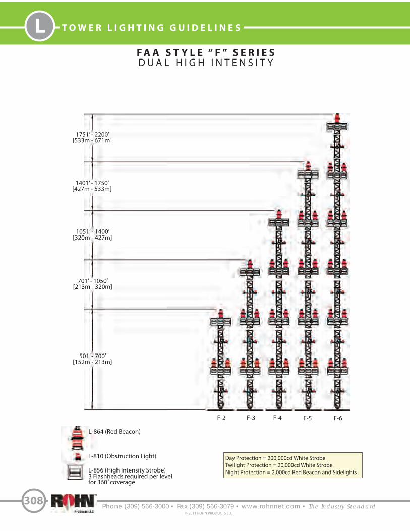
F A A S T Y L E “ F ” S E R I E S
D U A L H I G H I N T E N S I T Y
Phone (309) 566-3000 • Fax (309) 566-3079 • www.rohnnet.com • The Industry Standard
T O W E R L I G H T I N G G U I D E L I N E S
308
© 2011 ROHN PRODUCTS LLC
L
501’ - 700’[152m - 213m]
701’ - 1050’[213m - 320m]
1051’ - 1400’[320m - 427m]
1401’ - 1750’[427m - 533m]
1751’ - 2200’[533m - 671m]
F-2 F-3 F-4 F-5 F-6
L-864 (Red Beacon)
L-810 (Obstruction Light) Day Protection = 200,000cd White StrobeTwilight Protection = 20,000cd White StrobeNight Protection = 2,000cd Red Beacon and Sidelights
o
L-856 (High Intensity Strobe)3 Flashheads required per levelfor 360 coverage


R O H N C O N S T R U C T I O N S E R V I C E S
Phone (309) 566-3000 • Fax (309) 566-3079 • www.rohnnet.com • The Industry Standard
C O N S T R U C T I O N M A N A G E M E N T
310
© 2011 ROHN PRODUCTS LLC
I
ROHN’s Construction Group has direct and immediate access to company management, engineering, production and
shipment to provide you with the highest quality products and a wide range of services to help you complete your project.
This direct and simple line of communication saves time and eliminates long distance contact between the manufacturer
and installer. It enables us to answer questions internally before they have the chance to grow into costly delays.
We employ professionals with the expertise required to provide you a full turnkey communication project. We understand
your needs, and when your job becomes a ROHN Construction project, we assign a single sta! member to take charge.
This one point of contact provides you the answers from scope changes to shipping schedules. At any time, you can be
assured of the updated status of all phases of your project without having to contact multiple manufacturers and
contractors.
ROHN’s Construction Group, in addition to our in-house sta!, has a network of suppliers, consultants and contractors
to provide:
services more quickly and e#ciently than ROHN? Nobody knows the products and installation methods the way ROHN


C O N S I D E R A T I O N S I N E R E C T I N G
T O W E R S & S I M I L A R P R O D U C T S
Phone (309) 566-3000 • Fax (309) 566-3079 • www.rohnnet.com • The Industry Standard
C O N S I D E R A T I O N S I N E R E C T I N G T O W E R S
312
© 2011 ROHN PRODUCTS LLC
I
Your local municipality or development may have established height and building standards governing the use of towers and similar products. Height restrictions are found in zoning ordinances and private deed restrictions. Building standards may be found in local building codes. Complying with these requirements is usually easy and will help to provide many years of safe and trouble free operation of your installation.
Zoning ordinances, building codes and private deed restrictions are complex legal documents. If you question whether they apply to you, consult a local attorney. Five minutes spent in advance may save hours later.
Zoning ordinances, building codes and deed restrictions are local. If you move from city to city, these restrictions may change.
Zoning ordinances are concerned with the type of buildings or other structures you can erect in your neighborhood. In terms of towers and similar products, zoning laws will tell you if your property is zoned for such items, and if so, what height limitations, if any are involved.
Building codes are concerned with the safety of buildings or other structures permitted by local zoning ordinances. Building codes will tell you where on your property you can put the installation and the type of loading you will need to consider.
Both zoning and building codes are usually administered by the same governmental agency, often known as the Department ofBuilding and Safety or the Zoning Board.
The following steps will help make sure you have a safe, legal installation.
1. Check with the local governmental agency. Ask whether your home is zoned for the type of product you wish to install.
2. Look at the actual zoning ordinances. Pay special attention to the definitions. Many zoning ordinances distinguish between “buildings” and “structures”. Others distinguish between towers physically attached to the house, either by guy wires or mounting and towers that are not attached.
3. See if a building permit is required. If so, be sure to get one. They are usually quite inexpensive, often less than one percent of the cost of the tower. As part of the building permit, a local inspector will check and make sure that the base, guy wires, etc. meet local safety requirements. Properly manufactured commercially made towers are extremely safe and have a large safety margin, but only if you install them according to the directions! If a permit is required and not obtained, your home-owner’s insurance may not insure the tower and you have given neighbors, who might object, a reason to require you to take the tower down.
4. In a limited number of cases, you may need either a zoning variance or a conditional use permit to erect a structure higher than the local zoning board requirements. If so, it is far easier to apply in advance than to put up the structure and apply later. Most local governments are quite cooperative if you apply in advance and follow their rules. Variance provisions are used to provide flexibility from dimensional regulations such as setback or height restrictions. Conditional use permits are used where towers or antennas are not otherwise allowed. A public hearing is usually required before such permits are issued.
5. In addition to local ordinances, real estate developers or homeowners’ associations may impose their own requirements in a subdivision. These requirements are usually known as deed restrictions or Conditions, Covenants and Restrictions (CC&R).
If you are thinking of moving into a new area, ask for a copy of the deed restrictions in advance of signing an offer to purchase the property. If you already own a home, a local realtor, title insurance company or lawyer can obtain copies of the deed restrictions, if any,for you. Don’t take the word of the realtor who may be wrong.
If there are no deed restrictions, you need only be concerned with local zoning and building codes. If there are deed restrictions, read them carefully. Look at the definitions. See if there are any restrictions on outside structures or if a local architectural control committee must pass on any additions or changes to your property.
Deed restrictions are legal documents. A local lawyer familiar with real estate law can read the restrictions in only a few minutes and advise you. Even if the deed restrictions prohibit or restrict the size of towers and similar products, they may be unenforceable if many of your neighbors have erected such products and no objections have been raised.

Phone (309) 566-3000 • Fax (309) 566-3079 • www.rohnnet.com • The Industry Standard
IC O M M U N I C A T I O N T O W E R S P E C I F I C A T I O N S
313© 2011 ROHN PRODUCTS LLC
R E C O M M E N D A T I O N S F O R S P E C I F Y I N G C O M M U N I C A T I O N S T R U C T U R E S
The basic standard for the design of steel antenna supporting structures is ANSI/TIA-222-G. Prior to issuing a specification, the specifying authority must have a working familiarity with this standard and its requirements. The following information is presented as the basis for preparing a tower specification.
Location: The tower is to be installed at _________________________________________ (include site name, state and county).
Tower Requirements: The structure is to be guyed/self-support/pole (circle one) with a normal overall structural height of_________ feet. The tower is to be designed for a _________ mph wind speed as defined by ANSI/TIA-222-G.
Ice loading shall be considered at _________ inches per ANSI/TIA-222-G and ___________ mph wind speed.
The tower shall be designed to accommodate the following antenna loads: (At this point, please list all antennas, their mounting elevations, and transmission line requirements, providing as specific detail as possible. This should include microwave antenna azimuths, if known, and frequencies.)
Owner shall define structure class, exposure and topographic category (see pages 14-16).
The structure should be oriented on the property with one leg at _________ degrees, true north. Provide orientation if there is a specific orientation required due to property restrictions or desired by the purchaser. (Does not apply to poles).
The following appurtenances shall be incorporated into design as required by ANSI/TIA-222-G. (Note which appurtenances are to be provided with the structure.)
1. Climbing Ladder 2. Safety Device 3. Rest/Working Platforms 4. Transmission Line Support Ladders/Brackets 5. Obstruction Warning Lights and/or Paint 6. Antenna Mounts 7. Ice Shields 8. Grounding Materials 9. Waveguide Bridge 10. Port Size / Location for Poles
ROHN recommends the following requirements be included in specifications for the benefit of the purchaser:
The vendor shall be a manufacturer, primarily and continuously involved in the design and production of communication towers for at least ten years.
In order to specifically define responsibilities, the vendor shall maintain in-house control over the design and fabricating functions. Subcontracting of these responsibilities will be cause for rejection of a vendor’s proposal.
Each structural member shall be identified by a part number and all parts with the same part number must be interchangeable. This will result in tower sections capable of being installed in any 120 degree rotation. Match marking requirements of tower sections by the manufacturer, for proper assembly, shall not be acceptable.
Tower leg members shall utilize a 50 KSI minimum yield strength. Tubular leg members with flange splices shall maintain an open interior diameter through the flange plate at least as large as the inside diameter of the tube and shall be welded externally and internally. Flange leg connections shall utilize a minimum of four bolts per leg.
All fabricated tower members shall be hot-dip galvanized after fabrication per ASTM Standard A123. Hardware shall be galvanized per ASTM Standard A153 and B695. Other types of coatings are not acceptable.
Four sets of tower assembly drawings illustrating all component part numbers and their respective locations shall be provided. As a minimum, assembly drawing shall be accompanied by a letter sealed by a registered professional engineer licensed in the state in which construction is to be performed, certifying that the tower meets all design requirements per ANSI/TIA-222-G.
The tower manufacturer shall be an AISC Certified Fabricator and shall maintain the highest quality steel manufacturing standards for production. Only AWS Certified Welders shall be employed for tower fabrication. A fully qualified quality control department shall be employed with a quality control manual maintained to establish minimum acceptable fabrication standards, procedures and requirements for documentation.
With the use of ANSI/TIA-222-G and the procurement and user guidelines (Annex A), accompanied by the commentary noted above, a thorough specification can be developed.
Copyright 2011 by ROHN Products, LLC. All rights reserved.

G U I D E L I N E S F O R T H E P R E P A R A T I O N
O F A G E O T E C H N I C A L R E P O R T
Phone (309) 566-3000 • Fax (309) 566-3079 • www.rohnnet.com • The Industry Standard
G E O T E C H N I C A L R E P O R T G U I D E L I N E S
314
© 2011 ROHN PRODUCTS LLC
I
I. PURPOSE AND INTENT
a) The intended purpose of these guidelines is to assist the customer and/or owner to retain the services of a Geotechnical Engineer. b) It is not ROHN’s purpose or intent to supercede the Geotechnical Engineer’s knowledge, judgement and/or experience. It is the Geotechnical Engineer’s responsibility to add or delete from these items, based on local site conditions and other factors.
c) Additional information is provided in ANSI/TIA-222-G Annex G “Geotechnical Investigations”.
II. DISCLAIMER
a) ROHN will not accept any liability, either expressed or implied, for the use of, and omissions in, these guidelines.
III. EXPLORATORY BORINGS
a) Borings should be taken at tower legs for self-supporting towers and at the base and anchor points for guyed towers. For small self-supporting towers, two borings may suffice. For large self-supporting towers, one boring should be taken at each tower leg. A “small” self-supporting tower is assumed to have a face width less than 20 feet and a compression load less than 50 kips per leg. For pole structures, one boring may suffice.
b) The minimum boring depth should be 30 feet for pole structures, self-supporting towers and guyed tower bases. For guyed tower anchors, the minimum depth should be 15 feet. The actual depth of boring must be determined by the Geotechnical Engineer based on reactions, soil conditions and the type of foundation recommended.
c) If borings cannot be advanced to the desired depth, rock corings should be taken. Rock Quality Designation (RQD) values and compressive strengths should be determined.
IV. GEOTECHNICAL REPORT
a) The following properties, for each soil layer encountered, should be determined by field or laboratory testing and summarized in the geotechnical report:
1. Soil classification and elevations 2. Standard penetration values 3. Unconfined compression strength 4. Angle of internal friction 5. Cohesion 6. “In-Situ” soil density and moisture content 7. Rock quality designation (RQD) and percent rock sample recovered 8. Other properties unique to site conditions
b) The following items should be discussed in the geotechnical report:
1. Geological description of site 2. Observed and expected ground water conditions 3. Expected frost penetration depth 4. Corrosion potential of soil and corrosion protection recommendations 5. Site access and potential construction difficulties 6. Dewatering or site drainage requirements 7. Backfill material recommendations 8. Settlement considerations 9. Additional information to aid foundation designer 10. Recommended types of foundations 11. Design parameters for uplift, download and lateral load 12. Factor of safety considered when allowable vs. ultimate design parameters are provided 13. Recommended construction techniques and inspections

Phone (309) 566-3000 • Fax (309) 566-3079 • www.rohnnet.com • The Industry Standard
IS A F E T Y I N F O R M A T I O N
315© 2011 ROHN PRODUCTS LLC
This information may save you from death or injury. Do not attempt to install or dismantle any ROHN products until you have read and understood the information in this document.
Do not attempt to install or dismantle ROHN products near any type of power line. Should your installation come into contact with power lines, you can be killed! Be sure your installation is out of falling distance of any overhead wires – including the lead to any building. Read all instructions carefully before you begin, or better yet, call a professional – it may save your life.
ROHN’s ACWS sign must be attached to all poles, towers, guyed mast bases in a location which is conspicuous and readable from the ground so that all personnel are notified and warned. Aluminum wire is furnished for attaching signs. ROHN recommends you check frequently to make sure the sign has not been removed. These 6" x 9" signs may be ordered, specify part number ACWS.
Tower Erectors – Please see that these signs are attached per the instructions above before leaving the site.
Guyed and bracketed towers are not self-supporting at any height. When installing or dismantling a guyed tower always consult your local tower installer. The condition of a used tower is difficult to determine and in the process of dismantling you could be killed or injured. Dismantling and installation may require the use of temporary steel guys.
General Information & Precautions
ROHN field technicians, warning labels, catalogs, guy charts, etc. are available from ROHN. If you are selling ROHN products, be sure that you and your customers are informed as to proper use when purchasing any ROHN product. All towers, masts and poles should be installed ordismantled by experienced and trained personnel.
Mixing of Products
The mixing of so-called interchangeable copies of ROHN products with ROHN products is dangerous and voids all engineering or warranty data supplied by ROHN. Materials used by the so-called copies are not the same quality and have not been tested or engineered by ROHN.
Who should install or Dismantle ROHN Products?
Installing, dismantling and rigging ROHN products requires specialized skills and experience. Information supplied by ROHN assumes that all products will be installed or dismantled by personnel having these skills and having worked with similar products before. No one should attempt to install or dismantle ROHN products without these skills and experience. ROHN assumes no liability if faulty or dangerous practices are used. There are available trained and experienced personnel to assist in installation, maintenance, and disassembly. Contact your local installer if consultation or assistance is required.
What about used material?
ROHN does not recommend or warrant in any way the use of used materials. The use of used materials voids all warranties set forth byROHN because no one knows if the used material has been misused, overloaded, or damaged. If, for some reason, materials are re-used, all new, galvanized, high strength bolt assemblies must be used.
General Precautions
Anti-climb sections are available on all structures to prevent unauthorized persons from climbing. Installation and dismantling may require the use of temporary steel guys. All installations must be grounded per local and national codes. All types of installations must be thoroughly inspected by qualified personnel and re-marked with hazard and warning labels at least twice a year to ensure safety and proper performance. ROHN makes available many items, which may or may not be required for your particular installation. Some items available in various types and sizes are: safety climbing devices, ladders, safety cages, anti-climb devices, work platforms, F.A.A. painting and lighting, grounding, and fencing. Special product services and special packaging are also available. Based on local, state, or federal laws and building codes for your area, it may be necessary for your particular installation to have special items or be given special consideration. If there are any special requirements for your particular installation, be sure to include them in your request for quotation and on your order form. ROHN cannot be responsible for any omission at any time.
S A F E T Y I N F O R M A T I O N

S A F E T Y I N F O R M A T I O N
Phone (309) 566-3000 • Fax (309) 566-3079 • www.rohnnet.com • The Industry Standard
S A F E T Y I N F O R M A T I O N
316© 2011 ROHN PRODUCTS LLC
I
About OSHA
In accordance with the Occupational Safety and Health Act regulations, parts are available incorporating features, which will permit a safe product. It is a policy of ROHN Products to design and make our products safe to use without hazards to people and/or property. We ask that you list specific requirements you wish us to comply with in accordance with the intended use of a product. These requirements may or may not affect the price of the materials and equipment under consideration for purchase. We would be happy to answer any additional questions you may have.
About Step Bolts
Structures may or may not include step bolts. Step bolts are supplied as a convenience during construction. Step bolts are intended to beclimbed by professional Competent Climbers only. 100% Fall protection is required at all times. Climber safety devices are required on allstructures 10 ft. or greater in height. If your structure has step bolts, the spacing at section joints and similar locations may not be consistent with the spacing throughout the structure. Flange plates, guys, attachments to legs, appurtenances, etc. may be an obstructionto continuous climbing. Climbing step bolts is dangerous and can cause serious injury or death. Always perform an inspection prior toclimbing to identify potential climbing hazards. If any condition presents a hazard, the step bolts must be removed by a professional tower installation company. ROHN will not be responsible for the use of step bolts. If you wish to use step bolts, the responsibility fortheir use will be totally yours or your customers.
Installation & Dismantling Safety Instructions
Each year people are killed, mutilated, or receive severe permanent injuries when attempting to install or dismantle towers, poles, and other structures. In many of these cases, the victim was aware of the dangers of electrocution but did not take adequate steps to avoid the hazard. Good practice is to install your products away from power lines and obstructions. Your dealer carries a complete line of installation and grounding hardware. For your safety and to help you achieve a safe installation, please read and follow the safety precautions below. They may save your life! Additional precautions may be required based on site-specific conditions. 1. If you are not experienced in installing or dismantling, please, for your own safety as well as others, seek professional assistance. Consult your dealer.
2. Select your installation site with safety, as well as performance, in mind. REMEMBER: Power lines and phone lines look alike. For your safety, assume that any overhead lines can kill you.
3. Call your power company. Tell them your plans and ask them to look at your site. This is little inconvenience, considering your life is at stake.
4. Before you begin, plan your installation or dismantling procedure carefully. Successful installation or dismantling is largely a matter of coordination. Each person should be assigned to a specific task and should know what to do and when to do it. One person should be designated as the “boss” to call out instructions and watch for signs of trouble.
5. When installing or dismantling, REMEMBER: Do not use a metal ladder. Do not work on a wet or windy day or if a thunderstorm is approaching. Do dress properly – shoes with rubber soles and heels, rubber gloves, long sleeve shirt or jacket, and a hard hat and safety glasses.
6. If the assembly starts to drop, get away from it and let it fall. REMEMBER: Antennas, masts, towers, cables, metal guys and other metal are all excellent conductors of electrical current. Even the slightest touch of any of these parts to a power line completes an electrical path through the installer!
7. If any part of the assembly should contact a power line – Don’t touch it or try to remove it yourself. Call your local power company. They will remove it safely.
8. If an electrical accident should occur – don’t grab hold of the person in contact with the power line or you too may be electrocuted. Use a dry board, stick or rope to push or pull the victim away. Have someone call for medical help.

Phone (309) 566-3000 • Fax (309) 566-3079 • www.rohnnet.com • The Industry Standard
IT E R M S & C O N D I T I O N S
317© 2011 ROHN PRODUCTS LLC
1. All quotation, proposals, prices, or other terms are made for acceptance within 30 days (after 30 days, prices in effect at time of shipment will apply) and shipment within 30 days of purchase order date, unless otherwise stated. They are subject to change without notice; however, ROHN invites your request for an extension. They are also subject to Credit and Marketing Department approval prior to acceptance. No other price protection is available. 2. Every effort will be made to maintain shipping schedules, either on ROHN equipment or via common carrier. ROHN cannot be responsible for delays in shipping caused by state or local agencies with regard to permits, routing, weather, detours, etc. All deliveries and schedules are contingent on availability of raw materials, fuel, and transportation. ROHN will not be liable for damages on account of any delays or abnormalities caused in shipping due to causes beyond our reasonable control. ROHN reserves the right to make partial shipments and to submit invoices accordingly. 3. Changes or modifications to orders can be made only by written agreement executed by all parties affected thereby, which agreement shall include any price modification. 4. ROHN's responsibility ceases upon delivery of all shipments to the carrier. The unloading of all shipments is the responsibility of the Buyer, not the carrier or ROHN. Buyer is warned against receipting for merchandises until careful inspection has been made. Any claim made against ROHN must be made within 90 days after receipt of merchandise. All merchandise leaving ROHN’s factory has been carefully inspected and ROHN does not assume responsibility for damages or shortages which occur in transit. Buyer must make all claims and report all damages and losses to the delivering transportation company. 5. No federal, state, or local taxes are included in quoted prices. All quotations, proposals, prices, or other terms are subject to increase without notification by the amount of any sales, excise, or other tax levied or charged to seller by any governmental agency and any such tax will be passed onto purchaser as a tax or as an addition to the selling price. This also applies to all costs incurred due to local statutes or governmental regulations. 6. Orders are not subject to cancellation by Buyer except by written agreement with seller. Any order canceled, after any work has been done by ROHN, such as drawings, production, etc., will have a cancellation charge, to be determined solely at the discretion of ROHN for whatever work has been performed with a minimum of 25% of the purchase order price. If Buyer so chooses, he shall have the right to receive the material already performed at time of cancellation at the quoted price. If an order is canceled before any work has been done by ROHN, a $200 cancellation charge will apply. 7. Material received may not be returned by Buyer except by written agreement with seller. In all cases, permission must be secured from ROHN prior to the returning of any goods for credit. All returned goods are subject to a minimum service charge of 25%, plus all transportation charges, and are subject to inspection by ROHN. Returned goods will be offered and paid for only upon proof of purchase (i.e. invoice no.) and credit will be issued against invoice value. ROHN reserves the sole right to determine amount of credit to be issued on all goods returned for credit. Only standard, currently manufactured ROHN products may be considered for return and credit. Unsaleable products will be scrapped and no credit will be received. If returned goods are determined to have no value and Buyer wishes them returned, the Buyer will be charged return freight. Safety equipment, erection equipment, insulators, transformers, nuts and bolts are not returnable. 8. ROHN warrants the commercial items of its manufacture only, to be reasonably fit for the purpose for which they are manufactured and sold, provided, however, that this warranty shall be effective only if purchaser installs all material according to ROHN's recommendations and specifications and that purchaser during the warranty period shall regularly, not less than semi-annually, inspect and properly maintain all items. Any item found unfit for its purpose within 12 months from date of delivery will be repaired or replaced free of charge, F.O.B. ROHN's plant. ROHN shall be immediately notified in writing of such unfitness. ROHN reserves the sole right to determine if any material is to be repaired or replaced free of charge or to be supplied at ROHN's standard prices. Such obligation shall be limited to parts returned for inspection, properly packed and expenses prepaid, and providing inspection shall satisfactorily indicate defects. The warranty herein made is in lieu of all other warranties and, except as expressly stated herein, ROHN does not make and there are no warranties or obligations of any kind or nature whatsoever either expressed or implied including, but not restricted to, warranty or obligations as to product, material, workmanship, or manufacture or as to the use of the items covered hereby. ROHN shall not under any circumstances be liable to third persons for any claims for damages including direct, special, indirect, or consequential damages for any reason. The Buyer agrees to indemnify and to hold ROHN harmless for, of, and from any loss, claims, damages, expenses and attorney’s fees, including but not limited to, any fines, penalties and corrective measures ROHN may sustain by reason of Buyer’s failure to comply with said laws, rules, and regulations in connection with the performance of this sale. The above warranty warranted applies only to items manufactured by ROHN. Items not manufactured by ROHN are guaranteed only to the extent and in the manner warranted and guaranteed to ROHN by the manufacturer of
such items and then only to the extent ROHN is liable to enforce such warranty or guarantee. ROHN will assume no responsibility for the adequacy of any product if material is used which is not totally supplied by ROHN. The above sets forth the only warranty made by ROHN in connection with items manufactured or sold by it, and any provisions in any proposals, specifications, advertising, or other provisions hereof, are merely descriptive and are not to be construed as warranties made by ROHN. All warranties are void on drawings made by others, whether by a professional engineer, sealed or not, that are not rechecked by ROHN and approved by ROHN. ROHN assumes no liability for the adequacy of the drawings or the product. Without limiting the generality of the foregoing, the Buyer hereby indemnifies ROHN and hold ROHN harmless from any and all claims and/or damages (including direct, special, indirect or consequential damages, attorneys’ fees and costs) relating to or arising out of any highway structure or component not designed by ROHN. ROHN hereby disclaims any and all warranties, including express or implied warranties of merchantability and fitness for any particular purpose, relating to or arising out of metal fatigue. 9. ROHN reserves the right to change or modify the product and construction of any product manufactured by ROHN and to substitute material equal to or superior to that originally specified. 10. Buyer agrees not to disclose or make available to any third party processes, drawings, specifications, reports, photographs, data and other technical or proprietary information relating to ROHN products without obtaining prior written consent of ROHN. 11. No proposal, order, quotation, or acceptance may be changed or varied by verbal agreement, and all orders are accepted only under the provisions set forth herein. 12. Purchase orders and requests for quotations must be submitted in writing to ROHN. It is the responsibility of the Buyer or Buyer Representative to provide ROHN design criteria (environmental loads, equipment loads, operational limitations, geotechnical information, etc.) based on site-specific data. In designing the product for the Buyer, ROHN is relying solely and entirely on design criteria provided by the Buyer to ROHN. Without limiting the generality of the indemnities in these Terms & Conditions, the Buyer hereby indemnifies ROHN and holds ROHN harmless from and against any and all claims and/or damages (including direct, special, indirect or consequential damages, attorneys’ fees and costs) relating to or arising out of any inaccuracy or incompleteness in design criteria provided to ROHN by the Buyer, and the Buyer waives all claims against ROHN for same. 13. If outside source inspection, assembly, etc. is required prior to shipment of an order, $50.00 per man hour (plus equipment time, if applicable) is chargeable, with $300.00 as a minimum. 14. Any welding inspection required by Buyer or Buyer's specifications must be done at ROHN's plant prior to packing and shipment of material from ROHN's plant. 15. A minimum charge of $25.00 will be billed for special handling and preparation of material for air shipments. 16. ROHN reserves the right to apply all remittances and credit memos to the oldest outstanding balance in your account. No credits will be issued for any reason against a purchase order whose billing is more than 90 days old. Buyer corrections or complaints must be made within this period of time. 17. Standard catalog prices do not include special drawings or product evaluations. If any are required, there will be a charge. 18. ROHN at all times reserves the right to take pictures of any or all of its products after installation for advertising purposes, except those which are under classified governmental control. 19. The Buyer will be responsible for any extra charges incurred on prepaid shipments. 20. A service charge not to exceed 2% per month or maximum allowable per State law will be billed on all accounts not paid within 30 days of invoice date. 21. Minimum total net worth of merchandise which can be ordered is $100.00. Any orders placed for less will be billed at $100.00. 22. Storage charges will be .02% of invoice amount per day with a minimum charge of $8.00 a day. These charges will be invoiced on a monthly basis for material requested to be withheld from shipment starting 30 days from the initial notification from ROHN, that the material was available for shipment. 23. All CIA requirements must be met with certified checks or money orders to insure prompt shipment. 24. All expenses incurred by ROHN during any collection effort shall be charged to the Buyer. 25. There will be a minimum of a $100 fee per truck or container, for ROHN to receive, handle and pack for reshipment, any material not purchased through ROHN, but drop shipped to ROHN for shipment with a ROHN structure. This includes light kits, platforms, mounts, rigging equipment, etc. that is provided by others. There will be a minimum $250 per truck or container for those drop shipped items that must be handled with ROHN forklifts or other mechanical device.

Phone (309) 566-3000 • Fax (309) 566-3079 • www.rohnnet.com • The Industry Standard© 2011 ROHN PRODUCTS LLC
318
N O T E S

Phone (309) 566-3000 • Fax (309) 566-3079 • www.rohnnet.com • The Industry Standard 319© 2011 ROHN PRODUCTS LLC
N O T E S

Phone (309) 566-3000 • Fax (309) 566-3079 • www.rohnnet.com • The Industry Standard
I N F O R M A T I O N
320
© 2011 ROHN PRODUCTS LLC
I
The information contained in this catalog does not purport to cover all details or variations in
equipment nor provide for every possible contingency to be met in connection with installation,
operation or maintenance. ROHN assumes no obligation to revise any of the information contained
in this catalog if changes are made in criteria or evaluation techniques at a later date. Should
particular situations arise which are not covered su"ciently herein for the purchasers’ purposes,
the matter should be deferred to ROHN.
All towers, poles and masts must be installed and dismantled by experienced and trained personnel.
All installations must be thoroughly inspected by quali#ed personnel and remarked as required with hazard
and warning labels at least twice a year to ensure safety and proper performance.
All installations must be grounded per local and national codes.
The mixing of so-called interchangeable copies of ROHN products is dangerous and voids all data
or warranty supplied by ROHN. Materials used by others are not the same quality and have not been
tested or checked by ROHN to conform to the same quality standards. Mixing of non-ROHN items may
endanger lives and cause serious failures and #nancial misfortune for all concerned.

Manufacturing Locations:
6718 W. Plank Road
Peoria, IL 61604
#1 Fairholm Avenue
Peoria, IL 61603
Mailing Address:
PO Box 5999
Peoria, IL 61601-5999
Phone:
(309) 566-3000
(800) 727-ROHN (7646)
Fax:
(309) 566-3079
Web:
www.rohnnet.com
