the 1995 alp identifies the “future” design...runway length. based on the faa runway length...
TRANSCRIPT


Methow Valley State Airport
Airport Layout Plan Report
September 2010 3-1 Facility Requirements
Century West Engineering
CHAPTER THREE
AIRPORT FACILITY REQUIREMENTS
Introduction
This chapter uses the results of the inventory and aviation activity forecasts contained in Chapter
Two, as well as established planning criteria, to determine the airport facility requirements Methow
Valley State Airport through the current twenty-year planning period. The chapter contains detailed
descriptions for the applicable FAA airport design and airspace planning standards that are
consistent with the existing and forecast activity (including the design aircraft) for runways used by
large aircraft. Standards for both visual and non precision instrument approach capabilities are
presented based on the request for the FAA to evaluate the feasibility of developing an instrument
approach to the airport. Note: the outcome of the FAA evaluation was unknown at the time this
chapter was written; to maintain consistency, the original content has not been altered based on
subsequent evaluations.
The facility requirements evaluation is used to identify the adequacy or inadequacy of existing
airport facilities and to identify what new facilities may be needed during the planning period to
accommodate forecast demand or to meet FAA safety and design standards. Airport facility
requirements include runways, taxiways, pavement condition, navigational aids, lighting systems,
aircraft parking apron, hangars, fixed base operator (FBO) facilities, aircraft fueling, automobile
parking, utilities and surface access. Options for providing these facilities will be evaluated in
Chapter Four to determine the most practical, cost effective and efficient means for
implementation.
Summary of Key Issues
This section provides a brief overview of the key issues associated with conformance to FAA design
and safety standards at Methow Valley State Airport.
Prior Planning
The current Airport Layout Plan (ALP) drawing for Methow Valley State Airport was approved by
FAA and WSDOT Aviation in 1995. The “current” planning criteria reflected on the drawing was
based on a design aircraft in common use at the USFS smoke jumper base, a short takeoff and
landing (STOL) twin-engine turboprop (de Havilland DHC-6 Twin Otter). This aircraft is included in

Methow Valley State Airport
Airport Layout Plan Report
September 2010 3-2 Facility Requirements
Century West Engineering
FAA Airplane Design Group II (ADG II) and Aircraft Approach Category A.6 These design parameters
combine to create Airport Reference Code (ARC) A-II. The 1995 ALP identifies the “future” design
aircraft as a Beechcraft Super King Air 200 (ARC B-II). Both the DHC-6 and Beechcraft Super King Air
200 have a maximum takeoff weight of 12,500 pounds. By FAA definition, “small aircraft” weigh
12,500 pounds or less.
The 1995 ALP also indicates that airspace planning criteria was based on the requirements of small
aircraft. Current and future airspace planning for Runway 13/31 was based on visual approaches for
utility runways. By FAA definition, “utility” runways are designed for small aircraft (weighing 12,500
pounds or less).
The 1995 ALP depicts limited facility improvements on the west side of the runway including a new
apron and hangar sites. The plan recommended removal of several hangars located south of the
USFS complex on the east side of the runway. No future parallel taxiways or major access taxiways
are depicted on the drawing. The recommendations from the 1986 ALP to construct an east parallel
taxiway and an aircraft apron, fixed base operation (FBO) facilities and hangars near the northeast
corner of the airport were not maintained. Some facilities, such as the runway and taxiway widths
are largely consistent with ADG II dimensional standards. However, other standards such as aircraft
parking and building setbacks and runway protection zones are not consistent with ADG II
standards. The mixed use of small and large design standards reflected on the 1995 ALP does not
appear to reflect a facility configuration that is entirely adequate for ADG II design aircraft.
Activity
The updated forecasts of aviation activity for Methow Valley State Airport presented in Chapter
Two reflect modest air traffic volumes (2008: 3,700 annual takeoffs and landings, projected to
increase to 7,600 by 2030). Based on the type of aircraft used by the North Cascades Smokejumper
Base, medevac operators and general aviation users, the current and future airport reference code
(ARC) is A-II/B-II. These aircraft generally weigh above 12,500 pounds, which classifies them as
“large airplanes.” It is recognized that the majority of aircraft operations at Methow Valley State
Airport are associated with small single-engine airplanes. However, the unique demands of
government and privately-owned turbine aircraft operating at the airport meet the FAA criteria for
“substantial use” and definition as design aircraft.
6 ADG is based on wingspan and tail height of aircraft; Approach Category is based on the typical approach speed of an aircraft.
ADG II aircraft have wingspans 49 to 78.9 feet or tail heights from 20 to 30 feet. Approach Category A aircraft have approach
speeds less than 91 knots. Approach Category B aircraft have approach speeds from 91 knots or more but less than 121 knots.

Methow Valley State Airport
Airport Layout Plan Report
September 2010 3-3 Facility Requirements
Century West Engineering
Existing Facility Characteristics
Runway 13/31 reflects design related features that are consistent with use by large ADG II aircraft.
Runway Length. Based on the FAA runway length model, at 5,049 feet Runway 13/31 can
accommodate 100 percent of small aircraft (12,500 pounds or less) and 75 percent of large
aircraft weighing less than 60,000 pounds at 60 percent useful load on a typical summer
day.
Pavement Strength. Runway 13/31 has a runway weight bearing capacity of 30,000 pounds
for aircraft with a single-wheel landing gear. The standard pavement rating for runways
designed to accommodate small aircraft is 12,500 pounds. Pavement sections can typically
accommodate heavier aircraft that are equipped with a dual wheel landing gear, which are
common on larger business class turboprops and business jets.
Assessment
The above-noted characteristics indicate that Runway 13/31 has been designed to accommodate
large aircraft. The updated evaluation of airport design standards and airspace planning standards
for this project is intended to accurately reflect existing and future activity, which is in part
determined by facility design characteristics.
Based on the information noted above, it appears that previously-defined ADG II design standards
continue to be appropriate for both current and future facility planning (current/future: A-II/B-II)
for Runway 13/31. However, it also appears that based on the physical characteristics of Runway
13/31, standards consistent with use by “large aircraft” are appropriate. This specific change
presents a unique challenge to apply FAA standards to existing airfield facilities and the overall
airport footprint, which is constrained by both property ownership and physical features.
The airspace planning criteria historically used for Runway 13/31 is based on visual approaches.
Some interest in developing a nonprecision instrument approach has been expressed in recent
years and is noted in the 1986 airport master plan.7 The mountainous terrain surrounding the
airport will be the primary determinant in both the feasibility of establishing an approach and the
actual approach minimums (altitude and visibility) that can be obtained. Based on a preliminary
evaluation, it appears that a circling approach to the airport may be feasible, although the high
terrain would affect both the inbound and missed approach segments of a procedure, requiring
high minimum descent altitudes. For planning purposes, this type of instrument approach requires
the same airspace surfaces as an ordinary visual approach.
7 Master Plan Intercity/Methow Valley State Airport (1986, Reid Middleton)

Methow Valley State Airport
Airport Layout Plan Report
September 2010 3-4 Facility Requirements
Century West Engineering
Summary
The technical information contained in this chapter is intended to support the evaluation of options
by the airport owner (WSDOT Aviation) to address overall airport development considerations and
FAA standards. Future improvements at the airport will be based on decisions made by WSDOT
Aviation and the FAA about the feasibility of applying and meeting specific design standards.
Figures 3-1 and 3-2 depict specific items that do not fully conform to ADG II design standards and
FAR Part 77 airspace planning for large aircraft and visual approaches. As indicated in the figures,
there are two specific areas identified on the airport with a significant number of nonconforming
items: the south end of the runway (affected by Evans Road and the Methow River) and the east
side of the runway (affected by USFS facilities and aircraft hangars on and off airport property). The
runway safety area, object free area, and obstacle free zone are defined areas along both sides and
beyond the ends of a runway that are required be free of parked aircraft, structures or items.
Parallel taxiways are required be located outside of some of these clear areas. The standard ADG II
runway-parallel taxiway centerline separation is 240 feet. Figure 3-3 illustrates how a standard
parallel taxiway could be configured on either side of the runway (with the exception of the area
limited by the Methow River) and the existing facilities affected.
Note: the figures contained in this chapter are intended only to illustrate applicable FAA design
standards for the existing runway and do not presume acquisition of adjacent properties.
More detailed descriptions of the standards are provided later in this chapter. A discussion of
possible options to address the nonconforming items or other facility needs will be developed
through the alternatives evaluation in Chapter Four.


Methow Valley State Airport
Airport Layout Plan Report
September 2010 3-8 Facility Requirements
Century West Engineering
Land Utilization
The current FAA Airport Master Record (Form 5010-1) lists airport acreage at 65 acres. However, a
review of the current airport property ownership mapping indicates that overall acreage is
approximately 87 acres; WSDOT property records indicate total ownership is approximately 90.5
acres. An updated boundary survey and title search may be required to reconcile the varying
acreage estimates. Table 3-1 summarizes the existing areas and land uses, based on the estimated
87 acres and a review of aerial photography.
The airport land area includes the runway and its protected areas and landside areas on the east
and west side of the runway. As noted in the inventory, the existing airport land base is relatively
limited in size beyond the runway area. The west landside area includes the public aircraft parking
apron and previously a small hangar which was recently removed after its roof collapsed. USFS-
related helicopter parking and ground operations are also accommodated in the grass area along
the runway during fire season. The east landside area includes four hangars located south of the
USFS complex, and a small undeveloped area along the northern one-third of the runway.
TABLE 3-1: METHOW VALLEY STATE AIRPORT LAND USE CONFIGURATION
Existing Land Use Acreage
(rounded)
Percentage of Total Airport Property
(rounded)
Airside Area Runway, Runway Protection Zones, Object Free Area, Runway Safety Area, Obstacle Free Zone, Primary Surface
60.4 69%
West Landside Area Aircraft Parking Apron; helicopter parking
22.9 26%
East Landside Area Hangars and Undeveloped Land (does not include off-airport development)
3.7 4%
Total 87 100%
The airport’s available undeveloped west landside area appears to have adequate capacity to
accommodate the modest 20-year forecast demand for facilities (i.e., hangars, apron parking, etc.).
However, the shape and the limited depth of this land area significantly limit the configuration of
facilities. In addition, the existing airport property configuration does not fully accommodate
several protected areas for the runway. Without property acquisition, changes to Evans Road, or
modification to specific design standards, some shortening of Runway 13/31 may be required to
meet FAA design standards. The east side of the runway does not have sufficient area to
accommodate new hangars or aircraft parking, while observing FAA runway and/or future parallel
taxiway clearance standards.

Methow Valley State Airport
Airport Layout Plan Report
September 2010 3-9 Facility Requirements
Century West Engineering
AIRSPACE
The airspace structure in the vicinity of Methow Valley State Airport is uncomplicated and is not
expected to constrain future airport development or operation. Mountainous terrain in the vicinity
of the airport creates several unique operational considerations for pilots.
The FAR Part 77 airspace surfaces previously associated with Runway 13/31 were based on visual
approach capabilities and use by small aircraft (weighing less than 12,500 pounds).8,9 However, as
noted earlier, based on the runway’s physical characteristics and use airspace planning criteria for
runways designed to accommodate large aircraft (more than 12,500 pounds) is appropriate. The
updated analysis of airspace for Runway 13/31 will be based on “larger-than-utility” standards for
either visual or nonprecision instrument runways, depending on the findings of an FAA feasibility
assessment for instrument approach development being performed for the runway.
It is noted that visual PART 77 airspace surfaces are also compatible with circling instrument
approach procedures. A circling instrument approach provides guidance to the airport environment,
rather than a particular runway end, and the pilot must maintain visual contact with the airport
environment once passed the missed approach point. By comparison, a straight-in instrument
approach procedure is designed for a specific runway end and requires larger and flatter approach
surfaces, which can be more difficult to accommodate in a mountainous area.
The 1995 Airspace Plan depicts large areas of terrain penetration in the horizontal and conical
surfaces, west and east of the runway. Terrain penetrations to the airspace surfaces will be
reviewed during development of an updated FAR Part 77 airspace plan drawing (see Chapter Six).
The displaced thresholds located on both ends of Runway 13/31 mitigate close-in obstructions for
landing aircraft. However, displaced thresholds do not alter the configuration or obstruction
clearance for FAR Part 77 airspace surfaces. Options for relocating roadways away from runway
ends should be considered in the alternatives analysis to improve approach clearances and reduce
or eliminate the need for displaced thresholds.
AIRPORT DESIGN STANDARDS
The selection of the appropriate design standards for the development of airfield facilities is based
primarily upon the characteristics of the aircraft that are expected to use the airport. The most
critical characteristics are the approach speed and wingspan of the design aircraft anticipated for
the airport. The design aircraft is defined as the most demanding aircraft type operating at the
8 In FAR Part 77, utility runways are designed to accommodate aircraft weighing less than 12,500 pounds.
9 As depicted on current FAA-approved Airport Airspace Drawing (W&H Pacific 1995)

Methow Valley State Airport
Airport Layout Plan Report
September 2010 3-10 Facility Requirements
Century West Engineering
airport with a minimum of 500 annual itinerant operations (takeoffs and landings). This level of
annual activity is considered to be “substantial use” by FAA.
Federal Aviation Administration (FAA) Advisory Circular (AC) 150/5300-13, Airport Design, serves
as the primary reference in planning airfield facilities. Federal Air Regulation (FAR) Part 77, Objects
Affecting Navigable Airspace, defines airport imaginary surfaces, which are established to protect
the airspace immediately surrounding a runway. The airspace and ground areas surrounding a
runway should be free of obstructions (i.e., structures, parked aircraft, terrain, trees, etc.) to the
greatest extent possible.
FAA Advisory Circular 150/5300-13 groups aircraft into five categories based upon their approach
speed. Categories A and B include small propeller aircraft, some smaller business jet aircraft, and
some larger aircraft with approach speeds of less than 121 knots. Categories C, D, and E consist of
the remaining business jets as well as larger jet and propeller aircraft generally associated with
commercial and military use with approach speeds of 121 knots or more.
The advisory circular also establishes six airplane design groups (ADG), based on the physical size
(wingspan) of the aircraft. The categories range from ADG I, for aircraft with wingspans of less than
49 feet, to ADG VI for the largest commercial and military aircraft. ADG I is further divided into two
subcategories: runways serving “small airplanes exclusively” and runways serving aircraft weighing
more than 12,500 pounds. Aircraft with a maximum gross takeoff weight of less than 12,500 pounds
are classified as “small aircraft” by the FAA.
A summary of typical aircraft and their respective design categories is presented in Table 3-2. Figure
3-4 illustrates common aircraft types by airport reference code.

Methow Valley State Airport
Airport Layout Plan Report
September 2010 3-11 Facility Requirements
Century West Engineering
TABLE 3-2: TYPICAL AIRCRAFT & DESIGN CATEGORIES
Aircraft Airplane Design
Group Aircraft Approach
Category Maximum Gross Takeoff
Weight (Lbs)
Piper PA-28/32 Cherokee A I 2,550
Cessna 182 A I 2,950
Cirrus SR20 A I 3.000
Lancair Columbia 300 A I 3,400
Cessna 206 A I 3,600
Beechcraft Bonanza A36 A I 3,650
Cessna 210 A I 3,850
Socata/Aerospatiale TBM 700C2 A I 7,394
Beechcraft Baron 58 B I 6,200
Eclipse 500 B I 5,640
Cessna P337 Skymaster B I 4,630
Cessna 402 B I 6,300
Cessna 421 B I 7,450
Cessna Citation Mustang (CE525) B I 8,730
Cessna Citation CJ1 (CE525) B I 10,600
Beechcraft Super King Air 200 B II 12,500
Piper Malibu A II 4,300
Cessna Caravan 1 A II 8,000
Pilatus PC-12 A II 10,450
deHavilland DHC-6 Twin Otter A II 12,500
Casa C 212-200 Aviocar A II 16,976
Cessna Citation CJ2+ (CE525A) B II 12,500
Cessna Citation Bravo (CE550) B II 14,800
Beech King Air 350 B II 15,000
Cessna Citation Encore (CE560) B II 16,630
Cessna Citation Excel (CE560XL) B II 20,000
Shorts Sherpa (C-23A/330) B II 25,600
Shorts Sherpa (360) 60)
B II 26,453
Dassault Falcon 20 B II 28,660
Bombardier Learjet 45 C I 20,500
Bombardier Learjet 60 C I 23,100
Hawker HS125-700 C I 24,200
Gulfstream 100 C II 24,650
Cessna Citation Sovereign C II 30,250
Cessna Citation X C II 36,100
Bombardier Challenger 300 C II 37,500
Gulfstream III (G300) C II 68,700
Gulfstream IV (G450) D II 71,780
Source: FAA Advisory Circular (AC) 150/5300-13; Jane’s Aircraft Guide; aircraft manufacturer data.


Methow Valley State Airport
Airport Layout Plan Report
September 2010 3-13 Facility Requirements
Century West Engineering
Design Aircraft
Historically, the design aircraft for Methow State Airport has been the largest aircraft used on
regular basis to support smoke jumper operations. The 1995 Airport Layout Plan identifies the de
Havilland Twin Otter (DHC-6) as the “existing” design aircraft. The Twin Otter is a short field takeoff
and landing (STOL) aircraft that is capable of operating on unimproved runways with takeoff
distances 1,200 feet or less. The maximum takeoff weight for the Twin Otter is 12,500 pounds,
which is the upper limit for the FAA definition of “small aircraft.” The Twin Otter is included in
Aircraft Approach Category A and Airplane Design Group II, which results in Airport Reference Code
A-II.
The USFS smoke jumper operations also use the CASA 212, twin-engine turboprop aircraft. Like the
Twin Otter, the CASA 212 is an A-II aircraft capable of operating on short, unimproved runways.
However, the CASA 212 has a maximum gross takeoff weight of 16,976 pounds, which places it in
the “large” aircraft category. Other large twin-engine turboprops are used in smokejumper
operations including the Shorts C-23 Sherpa and a turboprop-conversion DC-3TP. The Shorts Sherpa
is a B-II aircraft and the DC-3TP is an A-III aircraft.
Methow Valley State Airport accommodates a variety business class aircraft on a limited basis.
Based in large part on the available runway dimensions and pavement strength, a wide variety of
business jets and turboprop aircraft are known to use the airport. It is estimated that this segment
of activity totals approximately 100 to 200 annual operations. Based on local accounts of the
aircraft types observed at the airport, they range from turboprops and smaller business jets (ARC B-
II, C-I) to large business jets (ARC C-II, D-II). One example is a Gulfstream III business jet (ARC C-II)
that transports the owners of a local ranch from Seattle, on average about two or three trips per
month, for about half the year (estimated to be less than 50 annual operations). Other corporate
aircraft are flown in owner, company, or fractional flight operations and charter flights, including
federal government agencies (ATF, Bureau of Reclamation, USFS, BLM, etc.).
Based on the predominance of Approach Category A and B ADG II aircraft operating at the airport,
Airport Reference Code B-II (large airplanes) is recommended for current and long-term planning
purposes. It is noted that the FAA airport design standards for Approach Category A and B aircraft
in Airplane Design Group II are identical, which makes combining A and B aircraft activity a
reasonable basis for defining facility requirements. The current and forecast levels of Approach
Category C and D activity are not sufficient to define the design aircraft per FAA standards.
The design standards for ADG II (visual and nonprecision instrument approaches) are summarized in
Table 3-3. A summary of Methow Valley State Airport’s current conformance with ADG II design
standards and FAR Part 77 airspace surfaces is presented in Table 3-4. The airport’s ability to meet
established design standards and development setbacks will require an evaluation of facility

Methow Valley State Airport
Airport Layout Plan Report
September 2010 3-14 Facility Requirements
Century West Engineering
reconfiguration/relocation, property acquisition and roadway closures/realignments. These issues
will be addressed in the alternatives analysis in Chapter Four.
Most A-II/B-II design standards that would be applied to Runway 13/31 will not significantly
increase if a basic nonprecision instrument approach is added. The protected areas and
development setbacks for runways serving large aircraft for both visual and nonprecision
instrument approaches are similar. However, an upgrade from visual to nonprecision (straight-in)
instrument approach capabilities significantly increases the dimensions of the FAR Part 77 approach
and horizontal surfaces. In addition, the 20:1 slope (20 feet horizontal distance for 1 foot of vertical
rise) required for a visual approach surface increases to 34:1 for a non-precision instrument
straight-in approach to a runway end.

Methow Valley State Airport
Airport Layout Plan Report
September 2010 3-15 Facility Requirements
Century West Engineering
TABLE 3-3: AIRPORT DESIGN STANDARDS SUMMARY
(DIMENSIONS IN FEET)
Standard Runway 13/31 Existing Conditions
ADG II1
A&B Aircraft
Visual Approaches
ADG II2
A&B Aircraft
Nonprecision Instrument
Runway Length 5,049 3,630/4,250 3 5,500
4
Runway Width 75 75 75
Runway Shoulder Width 10 10 10
Runway Safety Area Width
<150 5
(majority of runway meets ADG II width std; width and length at south end by
road and property ownership; north end limited by fence, irrigation ditch, and
property ownership
150 150
Runway Safety Area Length (Beyond Rwy End)
50 (south); 60 (north) 5
300 300
Obstacle-Free Zone Width / Length
Beyond Runway Ends
250 / 50 (south), 60 (north) 6
(majority of runway does not meets OFZ width std; width at south and north ends
limited by roads)
400 / 200 400 / 200
Object Free Area Width / Length Beyond
Runway Ends
250 / 50 (south), 60 (north) 6
(majority of runway does not meet OFA width std; width at south and north ends
limited by roads)
500 / 300 500 / 300
Primary Surface Width / Length Beyond
Runway Ends
<250 / 50 (south), 60 (north) 6
(majority of runway does not meet primary sfc width std; width at south end
limited by road; north end limited by fence)
500 / 200 500 / 200
Runway Protection Zone Length 1,000 7 1,000 1,000
Runway Protection Zone Inner Width 250 7 500 500
Runway Protection Zone Outer Width 450 7 700 700
Runway Centerline to:
Parallel Taxiway/Taxilane CL
Aircraft Parking Area
Building Restriction Line
Taxiway Width
Taxiway Shoulder Width
Taxiway Safety Area Width
Taxiway Object Free Area Width
Taxiway Centerline to Fixed or Movable
Object
Taxilane Object Free Area Width
Taxilane Centerline to Fixed or Movable
Object
N/A
250 (west) / 125 feet (east) 8
N/A (west) 130 (east) 11
30 (west) / 30-40 (east)
10
79
131
65.5
<115 14
<57.5 14
240
306 9
376 12
35
10
79
131
65.5
115
57.5
240
369 10
376 13
35
10
79
131
65.5
115
57.5

Methow Valley State Airport
Airport Layout Plan Report
September 2010 3-16 Facility Requirements
Century West Engineering
Table 3-3 Notes:
1. Larger-Than-Utility (visual) runways (Per FAR Part 77); all other dimensions reflect visual runways and runways with not
lower than 3/4-statute mile approach visibility minimums (per AC 150/5300-13). RPZ dimensions base on visual and not
lower than 1-mile approach visibility minimums.
2. Larger-Than-Utility (nonprecision instrument) runways (Per FAR Part 77); all other dimensions reflect visual runways and
runways with not lower than 3/4-statute mile approach visibility minimums (per AC 150/5300-13). RPZ dimensions base
on visual and not lower than 1-mile approach visibility minimums.
3. Runway lengths required to accommodate 95 and 100 percent of General Aviation Fleet 12,500 pounds or less. 87
degrees F, 18-foot change in runway centerline elevation.
4. Runway length required to accommodate 75 percent of Large Airplane Fleet (60,000 pounds or less) with 60 percent
useful load. 87 degrees F, 18-foot change in runway centerline elevation.
5. Width and length of standard B-II RSA is limited by adjacent roadways and other items; portions of RSA beyond both
runway ends appear to extend beyond airport property (airport control); minor elevated terrain (< 1 foot) may by located
within RSA along the sides and end of runway (conduct grading as required).
6. Width and length of OFZ, OFA and primary surface are limited by adjacent roadways and other items; portions of these
areas beyond both runway ends appear to extend off airport property (airport control).
7. RPZs extend beyond airport property at both ends of the runway.
8. The nearest aircraft parking position on the tiedown apron is approximately 225 feet from runway centerline.
9. Distance required for an ADG II (A&B Aircraft) parallel taxiway OFA and clear 8-foot aircraft tail height (typ. small single-
engine) in transitional surface for visual approach.
10. Distance required to protect an ADG II (A&B Aircraft) parallel taxiway OFA and clear 17-foot aircraft tail height
(typ.medium business jet) in transitional surface for nonprecision instrument approach.
11. The nearest hangar (east side of runway) is approximately 130 feet from runway centerline.
12. Distance required to protect an ADG II (A&B Aircraft) parallel taxiway OFA and to accommodate an 18-foot structure (at
the BRL) without penetrating the 7:1 Transitional Surface for visual approach (assumes 500-foot wide primary surface
required for “large airplanes”).
13. Distance required to protect an ADG II (A&B Aircraft) parallel taxiway OFA and to accommodate an 18-foot structure (at
the BRL) without penetrating the 7:1 Transitional Surface (assumes 500-foot wide primary surface required for “large
airplanes”).
14. Parked aircraft and tiedowns on West Apron located within ADG II taxilane OFAs.

Methow Valley State Airport
Airport Layout Plan Report
September 2010 3-17 Facility Requirements
Century West Engineering
TABLE 3-4: RUNWAY 13/31 CURRENT CONFORMANCE WITH FAA AIRPORT DESIGN & FAR PART 77 AIRSPACE PLANNING STANDARDS
Item ADG II
Visual and NTL ¾ Mile Visibility FAR Part 77: Visual (Larger than Utility)
ADG II Visual and NTL ¾ Mile Visibility
FAR Part 77: Non-Precision Instrument (Larger than Utility)
Runway Safety Area No No
Runway Object Free Area No No
Runway Obstacle Free Zone No No
Taxiway Safety Area Yes (public taxiway – west apron) Yes (public taxiway – west apron)
Taxiway Object Free Area Yes (public taxiway – west apron) Yes (public taxiway – west apron)
Taxilane Object Free Area Yes (public taxiway – west apron) Yes (public taxiway – west apron)
Building Restriction Line – West Yes Yes
Aircraft Parking Line – West No No
Building Restriction Line – East No No
Aircraft Parking Line – East No No
Runway Protection Zones No No
Runway-Parallel Taxiway Separation No
(private taxiway east side of runway) No
(private taxiway east side of runway)
Runway Width Yes Yes
Runway Length No No
Taxiway Width Yes (public taxiway – west apron) Yes (public taxiway – west apron)
Approach Surfaces (Req. Slope/Clear: Yes/No?)
20:1/No 34:1/No
Primary Surface (Clear) No No
Transitional Surface (Clear) No No
Horizontal Surface (Clear) No No
Conical Surface (Clear) No No
Runway Safety Area (RSA)
The FAA defines runway safety area (RSA) as “A defined surface surrounding the runway prepared or
suitable for reducing the risk of damage to airplanes in the event of an undershoot, overshoot, or
excursion from the runway.” Runway safety areas are most commonly used by aircraft that
inadvertently leave (or miss) the runway environment during landing or takeoff.
By FAA design standard, the RSA “shall be:
1) cleared and graded and have no potentially hazardous ruts, humps, depressions, or other
surface variations;
2) drained by grading or storm sewers to prevent water accumulation;
Methow Valley State Airport
Airport Layout Plan Report
September 2010 3-18 Facility Requirements
Century West Engineering
3) capable, under dry conditions, of supporting snow removal equipment, aircraft rescue and
firefighting equipment, and the occasional passage of aircraft without causing structural
damage to the aircraft; and
4) free of objects, except for objects that need to be located in the runway safety area because
of their function. Objects higher than 3 inches above grade should be constructed on low
impact resistant supports (frangible mounted structures) of the lowest practical height with
the frangible point no higher than 3 inches. Other objects such as manholes should be
constructed at grade. In no case should their height exceed 3 inches.”
The recommended transverse grade for the lateral RSA ranges between 1½ and 5 percent from
runway shoulder edges. The recommended longitudinal grade for the first 200 feet of extended RSA
beyond the runway end is 0 to 3 percent. The remainder of the RSA must remain below the runway
approach surface slope. The maximum negative grade allowed is 5 percent. Limits on longitudinal
grade changes are plus or minus 2 percent per 100 feet within the RSA.
The airport sponsor should regularly clear the RSA of brush or other debris and periodically grade
and compact the RSA to maintain FAA standards. Items located within the RSA, such as runway
edge lights or threshold lights are mounted on frangible supports (breakable coupling and
disconnect plug). Any future lighting (such as PAPI, REILS, etc.) located within the RSA will also need
to meet the FAA frangibility standard.
The FAA, emphasizing the significance placed on meeting runway safety area standards provides
the following guidance “RSA standards cannot be modified or waived like other design standards.
The dimensional standards remain in effect regardless of the presence of natural or man-made
objects or surface conditions that might create a hazard to aircraft that leave the runway surface…A
continuous evaluation of all practicable alternatives for improving each sub-standard RSA is required
until it meets all standards…”
Portions of the RSA for Runway 13/31 extend beyond airport property at both ends of the runway,
which limits the airport’s ability to control and protect the area. The south end of the RSA is
physically limited by the following items:
Evans Road, which is located approximately 75 feet from the runway at its nearest point.
A series of concrete highway barriers placed end to end (on airport property) to prevent
vehicles from driving from Evans Road on to the runway. The barriers extend approximately
1,400 feet, separating the road and runway, with approximately 290 feet located in the RSA.
The concrete barriers do not meet the “frangibility standard” established by FAA. Options
for replacing the barriers with frangible fencing should be considered.
Methow Valley State Airport
Airport Layout Plan Report
September 2010 3-19 Facility Requirements
Century West Engineering
The southern end of the RSA also extends beyond Evans Road, over a drainage associated
with the Methow River.
Other RSA non-conforming items:
The north end of the RSA is limited by a range fence and an irrigation ditch.
A portion of the southern-most access taxiway that parallels the runway on its east side is
located within the RSA.
The physical items and terrain limitations are continuous hazards to aircraft operating on the
runway; vehicles traveling on the roadway are occasional hazards. The RSA that is contained within
airport property appears to be relatively level and requires only periodic grading and compaction to
meet FAA surface condition standards.
ARC: A-II/B-II
Meeting the A-II/B-II standard for Runway 13/31 will require either eliminating or modifying the
conflicting items (road, fence, ditch, concrete barriers) or reconfiguring the runway. If any of the
conflicting items cannot be mitigated, the useable runway lengths may be reduced fully or partially,
through the use of declared distances to meet FAA standards. As noted in Table 3-4, the ADG II RSA
is 150 feet wide and extends 300 feet beyond the ends of the runway. Options for providing
standard RSA should be evaluated in the alternatives analysis.
Runway Object Free Area (OFA)
Runway object free areas (OFA) are two dimensional surfaces intended to be clear of ground
objects that protrude above the runway safety area edge elevation. Obstructions within the OFA
may interfere with aircraft flight in the immediate vicinity of the runway. The airport sponsor should
regularly clear the OFA of brush or other debris to maintain FAA standards.
The FAA defines the OFA clearing standard:
“The OFA clearing standard requires clearing the OFA of above ground objects protruding above the
runway safety area edge elevation. Except where precluded by other clearing standards, it is
acceptable to place objects that need to be located in the OFA for air navigation or aircraft ground
maneuvering purposes and to taxi and hold aircraft in the OFA. Objects non-essential for air
navigation or aircraft ground maneuvering purposes are not to be placed in the OFA. This includes
parked airplanes and agricultural operations.”
Portions of the OFA for Runway 13/31 extend beyond airport property along the side of the runway
(east side - approximately 3,600 feet of the runway; northeast, northwest and southwest corners)

Methow Valley State Airport
Airport Layout Plan Report
September 2010 3-20 Facility Requirements
Century West Engineering
and at both ends of the runway. The nonconforming items noted above for the RSA also conflict
with the OFA. Additional nonconforming items include four hangars (on airport) located on the east
side of the runway, the front section of the USFS apron, the three western-most buildings in the
USFS complex, a fence, and equipment storage. Another section of fencing located along the
southeast portion of the airport is also located in the OFA.
The west side of OFA and the south end are limited by Evans Road and the concrete barriers
between the road and the runway. Approximately 1,900 feet of Evans Road and 1,200 feet of the
concrete highway barriers are located in the OFA at the south end of the runway. The OFA that is
contained within airport property appears to be relatively level and requires only periodic grading
and clearing to meet FAA standards.
ARC: A-II/B-II
Meeting the A-II/B-II standard for Runway 13/31 will require either eliminating or modifying the
conflicting items (road, fence, ditch, concrete barriers) or a reconfiguration of the runway. If
conflicting items cannot be fully mitigated, modifications to the runway configuration and the use
of declared distances may be required to meet FAA standards. In addition, several existing hangars
and other buildings, and a portion of the USFS apron would need to be relocated outside the OFA to
meet the FAA clearing standard. As noted in Table 3-3, the ADG II OFA is 500 feet wide and extends
300 feet beyond the ends of the runway. Options for clearing the OFA should be evaluated in the
alternatives analysis.
Obstacle Free Zone (OFZ)
The OFZ is a plane of clear airspace extending upward to a height of 150 feet above runway
elevation, which coincides with the FAR Part 77 horizontal surface elevation. The FAA defines the
following clearing standard for the OFZ:
“The OFZ clearing standard precludes taxiing and parked airplanes and object penetrations, except
for frangible visual NAVAIDs that need to located in the OFZ because of their function.”
The OFZ may include the Runway OFZ, the Inner-approach OFZ (for runways with approach lighting
systems), and the Inner-transitional OFZ (for runways with lower than ¾-statute mile approach
visibility minimums. At Methow Valley State Airport, only the Runway OFZ is required based on
runway configuration and planned approach capabilities. The future development of aircraft
holding areas or new taxiway connections should be designed to allow holding aircraft to remain
clear of the OFZ. By standard, all items located within the OFZ should be frangible.
Methow Valley State Airport
Airport Layout Plan Report
September 2010 3-21 Facility Requirements
Century West Engineering
The FAA defines the Runway OFZ as:
“The runway OFZ is a defined volume of airspace centered above the runway centerline. The runway
OFZ is the airspace above a surface whose elevation at any point is the same as the elevation of the
nearest point on the runway centerline. The runway OFZ extends 200 feet beyond each end of the
runway.”
Many of the items that conflict with the RSA and OFA described earlier also conflict with the OFZ. In
addition to limitations described for the OFA, the OFZ clearing standard does not permit taxiing or
holding aircraft. The existing aircraft hold lines on taxiway connections to Runway 13/31 are located
125 feet from runway centerline, which is consistent with a Runway OFZ for small aircraft. Aircraft
hold lines should be located 200 feet from runway centerline to meet OFZ large aircraft clearance
standards. A portion of the USFS aircraft apron and one privately-owned hangar located on the east
side of the runway (immediately south of the USFS complex) are located within the OFZ. The
parallel section of access taxiway to the southern-most hangar on the east side of the runway is also
located in the OFZ; no aircraft hold lines were observed on the taxiway.
The aircraft turnarounds located at the ends of Runway 13/31 are contained entirely within the
OFZ. The turnarounds may be used to facilitate aircraft taxiing/turnaround before and after takeoff
or landing, but do not meet the FAA OFZ clearing standard for use as aircraft holding areas while
other aircraft takeoff or land on the runway.
ARC: A-II/B-II
Meeting the A-II/B-II standard for Runway 13/31 will require either eliminating or modifying the
conflicting items (road, fence, ditch, concrete barriers) or reconfiguring the runway. In addition, one
privately owned hangar and the USFS apron would need to be relocated outside the OFZ to meet
FAA standards. As noted in Table 3-3, the OFZ for runways accommodating large aircraft (above
12,500 pounds) is 400 feet wide (centered on the runway) and extends 200 feet beyond runway
end. Options for clearing the OFZ should be evaluated in the alternatives analysis.
Taxiway Safety Area
Methow Valley State Airport has several taxiways that provide access to aircraft parking areas and
hangars. The airport has one public taxiway that connects the west apron to the runway. All other
taxiways extend off airport property and are owned and maintained by the users.
ARC: A-II/B-II
The existing west access taxiway appears to meet ADG II standards for obstruction clearance within
the safety area, although the surface may require periodic grading to meet FAA standards. The

Methow Valley State Airport
Airport Layout Plan Report
September 2010 3-22 Facility Requirements
Century West Engineering
various taxiways that extend from the east side of the runway also appear to meet safety area
clearance standards.
Taxiway/Taxilane Object Free Area
A taxiway or taxilane object free area (OFA) is intended to protect taxiing aircraft from obstructions
that could interfere with safe movement, particularly at night or during reduced visibility
conditions. Based on FAA clearance requirements, no parked aircraft or structures should be
located within a taxiway or taxilane OFA.
The west apron is configured with a center taxilane located between two rows of aircraft tiedowns.
The taxilane centerline is located approximately 41 feet from the top of each painted tiedown “T,”
and the clearance between the two rows is approximately 82 feet. The spacing between taxilane
centerline and the adjacent aircraft tiedowns is consistent with typical apron designs for ADG I
aircraft. The south section of the apron is configured to accommodate large aircraft (ADG II),
although the spacing between the tiedowns and the taxilane centerline is the same as the north
section of apron. It is observed that the nose of an aircraft parked in the small tiedown positions
typically extends 3 to 5 feet ahead of the tiedown markings, which effectively reduces the clearance
between taxilane centerline and a parked aircraft to less than the FAA standard (39.5 feet) for ADG
I. Reconfiguration of tiedowns on the main apron to meet the clearing standard should be
considered and all future apron designs should provide adequate clearance between parked aircraft
and taxilane centerlines.
As noted earlier, the addition of an east parallel taxiway cannot be accomplished without removing
several existing hangars, in part to meet the taxiway OFA standards.
ARC: A-II/B-II
The existing west apron taxiway appears to meet ADG II standards for OFA clearance. The west
apron taxilanes do not fully meet ADG I or ADG II clearing standards.
Building Restriction Line (BRL)
A building restriction line (BRL) identifies areas on an airport where structures can be located to be
compatible with airfield operations. Buildings should not conflict with the recommended airport
design standards defined for a particular runway-taxiway system or the protected airspace
associated with the runway. The location of the BRL is measured from the runway centerline
outward in a perpendicular direction. BRL locations are established based on the ability to
accommodate common airport building types (e.g., T-hangars, small conventional hangars, large
conventional hangars, etc.) while protecting the FAR Part 77 primary and transitional surfaces that
extend outward along the sides of a runway.

Methow Valley State Airport
Airport Layout Plan Report
September 2010 3-23 Facility Requirements
Century West Engineering
All structures at Methow Valley State Airport are currently located on the east side of the runway. A
small hangar previously located near the northwest corner of the west apron was removed after its
roof collapsed. Four hangars are located on airport property; all other buildings located off airport
property.
The nearest building (hangar) is located approximately 135 feet from the centerline (east) of the
runway. Six other buildings are fully or partially located within 250 feet of the runway centerline
(inside the Runway OFA and primary surface). Several additional buildings are located between 250
and 500 feet from runway centerline. The back edge of the west aircraft apron is approximately 440
feet from runway centerline. At this distance, the area could accommodate structures with a top
roof elevation up to 27 feet above the runway.
Assuming level ground, an 18-foot tall structure would need to be located a minimum of 376 feet
from the runway centerline to clear all runway protected areas and to avoid penetrating the runway
transitional airspace surface that extends outward at a 7:1 slope from the sides of the primary
surface, beginning 250 feet from runway centerline. Larger buildings would require increased
separation distances, depending on their roof heights (based on their relative height above the
runway). All existing structures that penetrate FAR Part 77 airspace surfaces should be marked with
roof-mounted red obstruction lights or relocated if feasible. All new structures should be located
and designed to avoid FAR Part 77 surface penetrations.
A 376-foot BRL is also compatible with an ADG II parallel taxiway, which would be located 240 feet
from runway centerline. The ADG II taxiway OFA extends 65.5 feet from taxiway centerline, which is
305.5 feet from runway centerline. The area between a parallel taxiway OFA and the BRL could
accommodate aircraft parking.
ARC: A-II/B-II
Based on ADG II standards and larger-than-utility visual or nonprecision instrument runway
configuration, a BRL of 376 feet on both sides of Runway 13/31 is recommended to accommodate
18-foot tall structures; taller structures should be located to avoid transitional surface penetrations.
An increase in the BRL separation may be appropriate for the west side of the runway depending on
the configuration of the aircraft apron and potential hangar sites.
Runway Protection Zones (RPZ)
Runway protection zones (RPZ) are located at each end of a runway. The FAA provides the following
definition for runway protection zones (RPZ):
“The RPZ’s function is to enhance the protection of people and property on the ground. This is
achieved through airport owner control over RPZs. Such control includes clearing RPZ areas (and

Methow Valley State Airport
Airport Layout Plan Report
September 2010 3-24 Facility Requirements
Century West Engineering
maintaining them clear) of incompatible objects and activities. Control is preferably exercised
through the acquisition of property interest in the RPZ. The RPZ is trapezoidal in shape and centered
about the extended runway centerline. The RPZ begins 200 feet beyond the end of the area useable
for takeoff or landing.”
As noted above, RPZs with buildings, roadways, or other items do not fully comply with FAA
standards. It is recognized that realigning major surface roads routes located within the RPZs may
not be highly feasible. Where possible, Okanogan County should discourage development within
the RPZs (particularly structures) that is inconsistent with FAA standards.
The 1995 ALP depicts RPZ dimensions (250 x 450 x 1,000 feet) are consistent with design standards
based on the following criteria: “Facilities expected to serve small aircraft exclusively with visual and
not lower than 1-mile approach visibility minimums.”
As noted earlier, the design characteristics of Runway 13/31 are consistent with use by large
aircraft. As such, the appropriate RPZ dimensions (500 x 700 x 1,000 feet) are based on the
following FAA criteria: “Aircraft Approach Category A & B with visual and not lower than 1-mile
approach visibility minimums.”
WSDOT has acquired avigation easements for the portions of the smaller RPZs and other areas at
the runway ends that are not in airport ownership. Options for relocating roads away from runway
ends should be considered in the alternatives analysis. WSDOT should review existing avigation
easements within the defined large airplane RPZs to ensure that adequate protections are in place
upon approval of the updated ALP.
ARC: A-II/B-II
The RPZ dimensions 500 x 700 x 1,000 feet for Approach Category A and B aircraft; not lower than
1-mile approach visibility minimums should be applied to Runway 13 and 31.
Aircraft Parking Line (APL)
Aircraft parking lines (APL) are used to identify areas on an airport where aircraft can be parked
clear of all airfield protected areas and airspace.
The 1995 Airport Layout Plan does not depict aircraft parking lines on either side of Runway 13/31.
The Airspace Plan drawing depicts a 250-foot wide primary surface for Runway 13/31 based on
standards for small aircraft. No future parallel taxiways are depicted on the 1995 ALP.

Methow Valley State Airport
Airport Layout Plan Report
September 2010 3-25 Facility Requirements
Century West Engineering
West Landside Area
The nearest aircraft parking positions (8 tiedowns) on the west side of the runway are located
approximately 250 feet from runway centerline in the outer row of tiedowns on the west apron.
The outer edge of the apron coincides with edge of the 500-foot wide primary surface and
beginning of the transitional surface slope recommended for Runway 13/31. As a result, aircraft
parked in any of the tiedown positions located along the outside of apron penetrate the runway
transitional surface. The apron also has a back row of light aircraft tiedowns and large aircraft
parking positions that are located approximately 350 feet from runway centerline. Most aircraft
parked in these positions will not penetrate the transitional surface, although some larger business
jets or other large aircraft with tail heights greater than 20 feet may penetrate the surface. In the
aerial photography flown for this project, a Gulfstream III business jet is located in one of the large
aircraft parking positions. The nose of the aircraft is located in line with the top of the painted
tiedown markings, 350 feet from runway centerline. In this location, the tail of the aircraft (24.4
feet tall) would penetrate the transitional surface by approximately 3 feet (assuming the nose of
the aircraft is pointed toward the runway).
Some reconfiguration of the large aircraft parking positions may be possible to address the
transitional surface penetrations. Future apron expansion projects considered relocating the front
row of tiedowns to eliminate the transitional surface penetration.
East Landside Area
The nearest aircraft parking positions on the east side of the runway are located just beyond the
aircraft hold lines on the USFS apron (125 to 200 feet from runway centerline). The back section of
the USFS apron is connected to the front section at its south end, and extends to approximately 400
feet from runway centerline. There are no other designated aircraft parking aprons on the east side
of the runway, although several small aprons are located in front of individual hangars and some
aircraft park in unimproved areas adjacent to hangars on the east side of the runway.
ARC: A-II/B-II
An APL of 306 feet from runway centerline would be required to accommodate an 8-foot tail height
without penetrating the transitional surface for either a visual or nonprecision instrument runway.
This setback is also compatible with the clearances required for a parallel taxiway object free area
(65.6 feet from taxiway centerline) and a 240-foot runway to parallel taxiway separation (305.5
feet). Options for reconfiguring aircraft parking areas to conform to FAA design standards should be
evaluated in the alternatives analysis. Larger aircraft, such as typical medium business jet with a 17-
foot tail height (typ.) would require approximately 376 feet from runway centerline to avoid
penetrating the transitional surface.

Methow Valley State Airport
Airport Layout Plan Report
September 2010 3-26 Facility Requirements
Century West Engineering
Runway-Parallel Taxiway Separation
ARC: A-II/B-II
The ADG II standard separation (centerline to centerline) between the runway and a parallel
taxiway is 240 feet. Runway 13/31 is not currently equipped with a full- or partial-length parallel
taxiway and a lengthy back-taxi on the runway is required for aircraft to reach the turnarounds at
each runway end.
The addition of a parallel taxiway to a runway is most commonly designed to increase runway
capacity by reducing runway occupancy times for aircraft. At airports without significant capacity
constraints, parallel taxiways are often added to increase safety by reducing or eliminating the need
to back-taxi on runways. The latter example would apply to Runway 13/31.
The southern-most hangar access taxiway on the east side of the runway has a section that parallels
the runway, with a centerline-to-centerline separation of approximately 85 feet. Although the
taxiway is not used as a parallel taxiway, its parallel section is located entirely within the Runway
OFZ, which does not meet FAA standards.
As depicted in Figure 3-3, presented earlier, the future development of parallel taxiways on Runway
13/31 presents a challenge based on physical site constraints and the location of existing facilities.
Options for providing parallel taxiway access on the runway should be evaluated in the alternatives
analysis. There may be significant benefits in adding a partial-length parallel taxiway to the runway
end used most often for takeoff, thereby reducing runway back-taxiing for those operations. For
landing operations, the shortest distance from either end of the runway to the nearest taxiway exit
is approximately 1,500 to 2,000 feet, which allows most aircraft to stop and exit the runway without
having to turnaround and back-taxi.
FAR Part 77 Surfaces
Airspace planning for U.S. airports is defined by Federal Air Regulations (FAR) Part 77 – Objects
Affecting Navigable Airspace. FAR Part 77 defines imaginary surfaces (airspace) to be protected
around airports. Figures 3-5 and 3-6 illustrate plan and isometric views of the Part 77 surfaces. As
noted earlier in this chapter, “larger-than-utility” standards based on visual approach capabilities
(per Part 77) reflect current runway use and capabilities. The basic feasibility of developing an
instrument approach to the runway is being evaluated by FAA Flight Procedures staff. Both visual
and nonprecision instrument standards will be evaluated in this section. Once the FAA completes
the feasibility analysis, a decision will be made by WSDOT Aviation about defining long-term
airspace planning for Methow Valley State Airport.
Methow Valley State Airport
Airport Layout Plan Report
September 2010 3-27 Facility Requirements
Century West Engineering
The airspace plan drawing in the 1995 ALP drawing set used visual approach standards for utility
(small aircraft) runways. The drawing depicts 29 obstructions at the ends of the runway and along
the east side of the runway. Most built item obstructions (hangars, etc.) have not been eliminated.
It appears that some of the obstructions have been mitigated, although an obstruction survey
would be required to thoroughly identify the location and heights of all current obstructions based
on the selected airspace planning criteria.
Based on the airport design standards described earlier in the chapter, the use of “larger-than-
utility” airspace planning standards for Runway 13/31 is appropriate. As noted earlier, the FAA is
currently evaluating the technical feasibility to develop a nonprecision instrument approach to
either end of Runway 13/31 or the overall airport environment. For the purposes of this analysis,
both visual and nonprecision instrument standards for larger-than-utility runways will be addressed.
Table 3-5 summarizes FAR Part 77 standards for Runway 13/31 for both visual and nonprecision
instrument approaches.
A review of terrain penetrations and other physical obstructions to Part 77 surfaces will be
conducted during the update of the Airport Airspace Plan drawings (see Chapter Six). In cases
where obstructions are identified beyond airport property, avigation easements should be acquired
by the airport sponsor to preserve the integrity of the protected airspace, particularly within the
inner approach surfaces (generally corresponding to the runway protection zones). For obstructions
that cannot be removed or eliminated outright, red obstruction lights are recommended to increase
visual recognition of potential hazards to pilots operating the vicinity of the airport.
TABLE 3-5: FAR PART 77 AIRSPACE SURFACE DIMENSIONS
Item Larger-than-Utility1 (visual)
Larger-than-Utility1
(nonprecision instrument)2
Width of Primary Surface 500 feet 500 feet
Radius of Horizontal Surface 5,000 feet 10,000 feet
Approach Surface Width at End 1,500 feet 3,500 feet
Approach Surface Length 5,000 feet 10,000 feet
Approach Slope 20:1 34:1
1. Larger-Than-Utility runways are designed for aircraft weighing more than 12,500 pounds.
2. Instrument approach visibility minimums not lower than 1-mile.


Methow Valley State Airport
Airport Layout Plan Report
September 2010 3-30 Facility Requirements
Century West Engineering
Approach Surfaces
Runway approach surfaces extend outward and upward from each end of the primary surface,
along the extended runway centerline. As noted earlier, the dimensions and slope of approach
surfaces are determined by the type of aircraft intended to use the runway and most demanding
approach planned for the runway.
Providing unobstructed approaches to runway ends is a high priority item associated with airport
safety. When obstructions exist, options include removing, lowering or relocating the obstructions;
or modifying runway approaches and/or runway configurations. Use of obstacle clearance surfaces
(OCS) is often recommended in conjunction with obstruction removal to mitigate close-in
obstructions that cannot otherwise be eliminated.
The 1995 ALP Airspace Plan drawing depicts 20:1 visual approaches for utility runways. The
approach surfaces extend 5,000 feet from each runway end. No terrain penetrations are depicted
for the approach surfaces. Close-in obstructions (roads, fences, etc.) are depicted at both runway
ends. Evans Road passes through the inner end of the approach surface where it connects to the
primary surface, which results in a 0:1 clear approach. A recommendation to displace the runway
landing thresholds was completed in a subsequent runway reconstruction project based on a 250-
foot inner width of the approach surface. The 1995 ALP Airspace drawings also recommended
obstacle clearance surfaces (OCS) for both runway ends based on standards for small aircraft and
visual approaches.
If existing visual approach capabilities are maintained, the runway approach surfaces retain the
same length (5,000 feet) and slope (20:1) as the previously depicted surfaces. However, the inner
width (500 feet) and outer width (1,500 feet) of the approach surfaces are larger than the visual
surfaces previously depicted. The use of an OCS appropriate for large aircraft and visual approaches
may require an increase in the displaced threshold distances, which would reduce available runway
length for landing.
The potential addition of a straight-in nonprecision instrument approach would enlarge the
approach surface to 10,000 feet long and the increase (flatten) the approach slope to 34:1. OCS
dimensional standards for runway ends with instrument approaches also increase over the surfaces
for visual approaches. Options for providing clear approaches to the runway ends will be addressed
in the alternatives analysis.
Primary Surface
The primary surface is a rectangular plane of airspace, which rests on a runway (at centerline
elevation) and extends 200 feet beyond the runway end. The primary surface end connects to the

Methow Valley State Airport
Airport Layout Plan Report
September 2010 3-31 Facility Requirements
Century West Engineering
inner portion of the runway approach surface. The width of the primary surface is determined by
the runway category and approach type. The primary surface should be free of any penetrations,
except items with locations fixed by function (i.e., PAPI, runway or taxiway edge lights, etc.).
The 1995 ALP Airspace Plan drawing depicts a 250 foot wide primary surface for Runway 13/31. Six
primary surface obstructions were identified with recommended dispositions ranging from removal
to no action. It is noted that by applying the 500-foot primary surface to Runway 13/31, the number
of primary surface penetrations will increase significantly, particularly on the east side of the
runway. Most of the items previously noted that do not conform with the ADG II runway OFA
clearing standards also apply to the primary surface (same width dimension).
As noted earlier, the 500-foot wide primary surface required for Runway 13/31 applies to both
visual and straight-in nonprecision instrument approaches. The standard primary surface for the
existing 5,049-foot runway extends beyond the airport property lines along most of the east side of
the runway and at both ends of the runway (northwest and southwest corners). Approximately
1,200 feet of Evans Road is located in the primary surface near the end of Runway 31. Vehicles
traveling on the road penetrate the primary surface and addition to the runway approach and
transitional surfaces.
Transitional Surface
The transitional surface is located at the outer edges of the primary surface for the runway,
represented by two planes of airspace that rises perpendicularly at a slope of 7 to 1, until reaching
the horizontal surface at an elevation 150 feet above runway elevation. This surface should be free
of obstructions (i.e., parked aircraft, hangars, trees, etc.). Any structures penetrating transitional
surfaces should have roof-mounted obstruction lights if they cannot be relocated. Relocation of
existing buildings may also be considered where feasible and no new structures should be
permitted that would penetrate the transitional surface.
No areas of terrain penetration are depicted within the transitional surface for Runway 13/31 on
the 1995 ALP Airspace Plan. It appears that the transitional surface extending from the runway’s
500-foot wide primary surface will also not be penetrated by terrain. Vehicles traveling on Evans
Road penetrate the west side transitional surface where it connects to the primary surface.
The transitional surfaces for Runway 13/31 associated with either a straight-in nonprecision
instrument approach or a visual approach begins 250 feet from the runway centerline. The east side
transitional surface appears to be penetrated by several off-airport structures located in close
proximity to the runway. As noted earlier, all penetrating items that cannot be removed or
relocated should be marked with red obstruction lights.

Methow Valley State Airport
Airport Layout Plan Report
September 2010 3-32 Facility Requirements
Century West Engineering
Horizontal Surface
The horizontal surface is a flat plane of airspace located 150 feet above runway elevation.
Depending on the runway designation, the outer boundary of the horizontal surface is defined by
5,000- or 10,000-foot radii, extending from the runway ends (the intersection point of the extended
runway centerline, the outer edge of primary surface, and the inner edge of the approach surface).
The outer points of the radii for each runway end are connected to form a semi-oval shape, which is
defined as the horizontal surface. The elevation of the existing horizontal surface is based on the
published elevation of the airport (1,706 feet MSL), plus 150 feet (1,856 feet).
The 1995 ALP Airspace Plan drawing depicts large areas of terrain penetration within the horizontal
surface east and west of the airport, along the sides of the valley. The areas of horizontal surface
terrain penetration would increase significantly if the surface is increase from 5,000 (visual) to
10,000 feet (nonprecision instrument). The degree to which increased terrain penetration is
significant will be reflected in the FAA’s technical evaluation of instrument approach feasibility and
potential approach minimums. In general, the presence of close-in terrain increases instrument
approach minimums considerably. This information will be used in determining whether an upgrade
from visual to instrument approach capabilities is both feasible and practical.
Conical Surface
The conical surface is an outer band of airspace, which abuts the horizontal surface. The conical
surface begins at the elevation of the horizontal surface and extends outward 4,000 feet at a slope
of 20:1. The top elevation of the conical surface (2,056 feet MSL) is 350 feet above airport elevation
(1,706 feet MSL). The 1995 ALP Airspace Plan drawing depicts large areas of terrain penetration
within the conical surface east and west of the airport, along the sides of the valley. Increasing the
radius of the horizontal surface, as described earlier, will likely also increase conical surface terrain
penetrations.
AIRSIDE REQUIREMENTS
Airside facilities are those directly related to the arrival and departure and movement of aircraft:
• Runways
• Taxiways
• Airfield Instrumentation and Lighting

Methow Valley State Airport
Airport Layout Plan Report
September 2010 3-33 Facility Requirements
Century West Engineering
Runways
The adequacy of the existing runway system at Methow Valley State Airport was analyzed from a
number of perspectives including runway orientation, airfield capacity, runway length, and
pavement strength.
Runway Orientation
The orientation of runways for takeoff and landing operations is primarily a function of wind
velocity and direction, combined with the ability of aircraft to operate under adverse wind
conditions. When landing and taking off, aircraft are able to maneuver on a runway as long as the
wind component perpendicular to the aircraft's direction of travel (defined as crosswind) is not
excessive. For runway planning and design, a crosswind component is considered excessive at 12
miles per hour for smaller aircraft (gross takeoff weight 12,500 pounds or less) and 15 miles per
hour for larger aircraft. FAA planning standards indicate that an airport should be planned with the
capability to operate under allowable wind conditions at least 95 percent of the time.
No tabulated wind data is available for Methow Valley State Airport. Although the wind coverage on
Runway 13/31 is generally believed to be adequate, occasional crosswind conditions would be
expected. The airport is situated within valley created by the Methow River with rising terrain
located on either side.
It appears that the current runway alignment was determined when the airport was first developed
as early as the 1930s or 1940s. The airport site is relatively narrow and could not accommodate
changes in runway alignment without significant property acquisition and relocation of existing
tenants. It is noted that Runway 10/28 at Twisp Municipal Airport is aligned within approximately
30 degrees of Runway 13/31. In both cases, prevailing winds from the west-northwest are generally
aligned with the runways, although quartering crosswinds are common.
It is believed that none of the airports located nearby with tabulated wind data would be useful for
comparison with Methow Valley State Airport to gauge wind coverage due to the effect of
surrounding mountainous terrain on local wind patterns.
Runway Length
Runway length requirements are based primarily upon airport elevation, mean maximum daily
temperature of the hottest month, runway gradient, and the critical aircraft type expected to use
the runway. The existing dimensions and pavement strength of Runway 13/31 are consistent with
FAA design criteria established for large airplanes.
Methow Valley State Airport
Airport Layout Plan Report
September 2010 3-34 Facility Requirements
Century West Engineering
Runway 13/31 accommodates small single engine and multi-engine piston aircraft and turbine
aircraft, including business class turboprops and business jets and a variety of aircraft used in fire
related operations and medevac flights. Many of these aircraft weigh more than 12,500 pounds.
The airport also regularly accommodates a smaller number of large business jets weighing more
than 60,000 pounds, including a Gulfstream III operated by a local ranch owner.
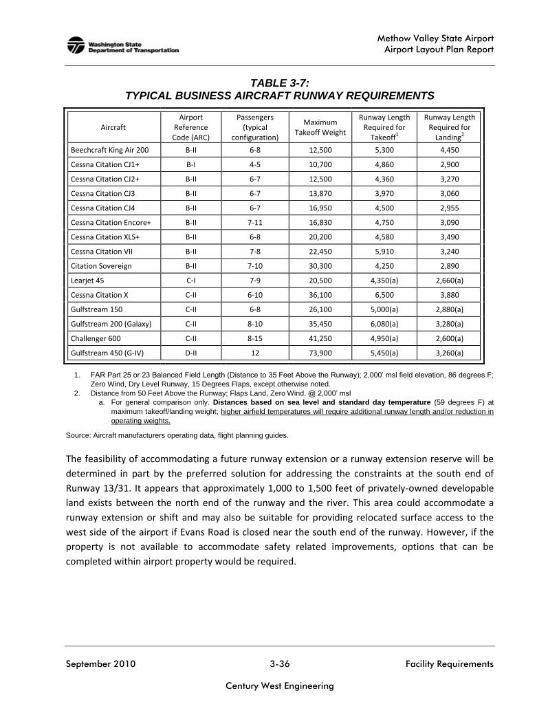
For planning purposes, general aviation (GA) runways used by larger business class aircraft typically
have length requirements greater than the small airplane fleet, consistent with the specific needs of
the design aircraft or family of design aircraft. A summary of FAA-recommended runway lengths
based on local conditions is presented in Table 3-6. For comparison, the runway length
requirements of several specific ADG II business jets are also summarized in the table and in Table
3-7.

Methow Valley State Airport
Airport Layout Plan Report
September 2010 3-35 Facility Requirements
Century West Engineering
TABLE 3-6: FAA-RECOMMENDED RUNWAY LENGTHS (From FAA Computer Model)
Runway Length Parameters for Methow Valley State Airport
Airport Elevation: 1,706 feet MSL
Mean Max Temperature in Hottest Month: 86.6F
Maximum Difference in Runway Centerline Elevation: 18 feet
Existing Runway Length: Runway 13/31 - 5,049 feet
Small Airplanes with less than 10 seats: 75 percent of these airplanes 95 percent of these airplanes 100 percent of these airplanes Small airplanes with 10 or more seats
Large Airplanes of 60,000 pounds or less: 75 percent of these airplanes at 60 percent useful load 75 percent of these airplanes at 90 percent useful load 100 percent of these airplanes at 60 percent useful load 100 percent of these airplanes at 90 percent useful load
Selected Small/Medium Business Jets: Cessna Citation CJ2 (6-7 passengers / 1 crew 12,375# MGW)
Cessna Citation Encore (7-11 passengers / 2 crew 16,375# MGW) Cessna Citation Excel (6-8 passengers / 2 crew 20,000# MGW)
3,040 feet 3,630 feet 4,250 feet 4,530 feet
5,500 feet 7,000 feet 5,980 feet 8,820 feet
4,300 feet* 4,570 feet* 4,640 feet*
* Takeoff distances based on maximum gross weight and conditions listed above under balanced field requirements defined in FAR Part 25; passenger and/or fuel loads may be reduced based on aircraft operating weight limits and runway length available. Runway length requirements based on 15 degrees flaps, 86 degrees F, MGTW, distance to 35 feet above the runway, and a runway elevation of 1,694 feet; data provided by manufacturer (Cessna Citation Flight Planning Guides).
At 5,049 feet, Runway 13/31 is 451 feet shorter than the length recommended to accommodate 75
percent of the larger airplane fleet at 60 percent useful load under the conditions common during a
typical summer day at the airport. Useful load is defined as the amount of passengers, baggage,
freight and fuel that can be carried on a particular aircraft.
The existing runway length is generally considered to be adequate for existing use, although it is
recognized that the current configuration does not meet several FAA design standards. Both ends of
Runway 13/31 are constrained by roads, other physical items and property ownership. An increase
in the length of Runway 13/31 or the ability to meet conventional ADG II standards for RSA, OFA,
and OFZ for the current runway length is not feasible without property acquisition. The realignment
or closure of Evans Road at the south end of the runway or a significant shift of the runway to the
north would be required to meet several FAA design standards for the existing runway. If property
acquisition or road reconfigurations are not possible, the use of declared distances and modified
runway configurations may be considered, or the runway length may need to be reduced to meet
ADG II standards.
Methow Valley State Airport
Airport Layout Plan Report
September 2010 3-36 Facility Requirements
Century West Engineering
TABLE 3-7: TYPICAL BUSINESS AIRCRAFT RUNWAY REQUIREMENTS
Aircraft Airport
Reference Code (ARC)
Passengers (typical
configuration)
Maximum Takeoff Weight
Runway Length Required for
Takeoff1
Runway Length Required for
Landing2
Beechcraft King Air 200 B-II 6-8 12,500 5,300 4,450
Cessna Citation CJ1+ B-I 4-5 10,700 4,860 2,900
Cessna Citation CJ2+ B-II 6-7 12,500 4,360 3,270
Cessna Citation CJ3 B-II 6-7 13,870 3,970 3,060
Cessna Citation CJ4 B-II 6-7 16,950 4,500 2,955
Cessna Citation Encore+ B-II 7-11 16,830 4,750 3,090
Cessna Citation XLS+ B-II 6-8 20,200 4,580 3,490
Cessna Citation VII B-II 7-8 22,450 5,910 3,240
Citation Sovereign B-II 7-10 30,300 4,250 2,890
Learjet 45 C-I 7-9 20,500 4,350(a) 2,660(a)
Cessna Citation X C-II 6-10 36,100 6,500 3,880
Gulfstream 150 C-II 6-8 26,100 5,000(a) 2,880(a)
Gulfstream 200 (Galaxy) C-II 8-10 35,450 6,080(a) 3,280(a)
Challenger 600 C-II 8-15 41,250 4,950(a) 2,600(a)
Gulfstream 450 (G-IV) D-II 12 73,900 5,450(a) 3,260(a)
1. FAR Part 25 or 23 Balanced Field Length (Distance to 35 Feet Above the Runway); 2,000’ msl field elevation, 86 degrees F;
Zero Wind, Dry Level Runway, 15 Degrees Flaps, except otherwise noted.
2. Distance from 50 Feet Above the Runway; Flaps Land, Zero Wind. @ 2,000’ msl
a. For general comparison only. Distances based on sea level and standard day temperature (59 degrees F) at
maximum takeoff/landing weight; higher airfield temperatures will require additional runway length and/or reduction in
operating weights.
Source: Aircraft manufacturers operating data, flight planning guides.
The feasibility of accommodating a future runway extension or a runway extension reserve will be
determined in part by the preferred solution for addressing the constraints at the south end of
Runway 13/31. It appears that approximately 1,000 to 1,500 feet of privately-owned developable
land exists between the north end of the runway and the river. This area could accommodate a
runway extension or shift and may also be suitable for providing relocated surface access to the
west side of the airport if Evans Road is closed near the south end of the runway. However, if the
property is not available to accommodate safety related improvements, options that can be
completed within airport property would be required.
Methow Valley State Airport
Airport Layout Plan Report
September 2010 3-37 Facility Requirements
Century West Engineering
Family Grouping of Aircraft
The majority of business jet aircraft and the CASA 212 used for smoke jumping during fire season at
Methow Valley State Airport are categorized as “large aircraft” by FAA based on their maximum
gross takeoff weights (MGTW) above 12,500 pounds. It is estimated that these aircraft currently
generate approximately 500 annual operations. A variety of “small” ADG II aircraft are estimated to
currently generate approximately 50 annual operations.
FAA Advisory Circular (AC) 150/5325-4B prescribes a particular design approach based on the
appropriate airplane weight category of the design aircraft.10 Based on the current and future
design aircraft weighing over 12,500 pounds and less than 60,000 pounds, the recommended
design approach is based on the needs of the “Family Grouping of Large Airplanes,” rather than the
requirements associated with a specific aircraft model or type. The majority of these aircraft are
listed in FAA AC 150/5325-4B Table 3-1, Aircraft that Make Up 75 Percent of the Fleet. The use of
performance curves based on the 75 percent of the family of large aircraft provides the
recommended runway lengths based on several airport-specific inputs and the percentage of
aircraft useful load to be accommodated.
It appears that the existing runway can accommodate a wide range of business jet aircraft (Lear,
Gulfstream, Falcon, Hawker, etc.) at less than maximum gross takeoff weights. As noted earlier, the
airport accommodates a limited amount of large business jet activity (aircraft weighing more than
60,000 pounds). A local ranch operates a Gulfstream III two or three times per month during part of
the year from its home airport in Seattle (Boeing Field). Other corporate and charter aircraft
including a variety of Gulfstream models are known to use the airport on a limited basis.
Since the volume of Approach Category C or D aircraft is expected to remain well below the levels
needed to meet the criteria for design aircraft, the use of the 75% of the large aircraft fleet (most
consistent with ARC: B-II) at 60% useful load is considered reasonable planning standard. It is also
noted that the physical capabilities of the existing site would be difficult to overcome in meeting
the increased lateral separations between the runway, parallel taxiways and adjacent aircraft
parking and hangar areas.
The existing width of Runway 13/31 is 75 feet, which meets the ADG II standard of 75 feet.
10
Chapter 3 Runway Lengths for Airplanes Within a Maximum Certificated Takeoff Weight of More than 12,500 Pounds Up To
and Including 60,000 Pounds.

Methow Valley State Airport
Airport Layout Plan Report
September 2010 3-38 Facility Requirements
Century West Engineering
Airfield Pavement
The weight bearing capacity for Runway 13/31 is 30,000 pounds for aircraft with single wheel (SW)
landing gear, which is consistent with use by large aircraft.11 According to available pavement data,
Runway 13/31 has a 3-inch asphalt surface course (1996) over a 6-inch crushed aggregate base and
a 5-inch aggregate base. The west tiedown apron was constructed at the same time as the runway,
with the same section design.
Based on 2005 inspections,12 most pavements at Methow Valley State Airport were rated “good” or
better with pavement condition indices (PCI) ranging from 12 to 100. The runway, USFS apron, west
apron and west taxiway, and other taxiways were rated “very good” or “excellent.” The circular
taxiway (private) located near the off-airport fueling area was rated “very poor.”
Most airfield pavements are projected to be in “good” or “very good” condition in 2015, although
some sections are projected to be in “poor” or “very poor” condition. The pavement maintenance
plan contains a recommended 7-year program of pavement maintenance for the airport. It is noted
that the pavement inventory for Methow Valley State Airport includes several private and USFS
taxiways and aprons. In general, FAA or WSDOT pavement maintenance funds can only be used for
airport-owned pavements. Table 3-8 summarizes recommended items (preventative maintenance)
for the initial seven-year period and items anticipated during the remainder of the current twenty-
year planning period.
11
Published pavement strength in FAA Airport/Facility Directory (A/FD) 12
Applied Pavement Technology (2005).

Methow Valley State Airport
Airport Layout Plan Report
September 2010 3-39 Facility Requirements
Century West Engineering
TABLE 3-8: SUMMARY OF RECOMMENDED AIRFIELD PAVEMENT MAINTENANCE
Pavement Section 7-Year Recommended Maintenance Other Recommended
Maintenance During 20-Year Planning Period
Runway 13/31
Preventive Maintenance (Vegetation control, crack filling, periodic sealcoats, etc.)
Overlay/Rehabilitation; Sealcoats or Slurry Seals on 5 to 6 year intervals
West Apron & Taxiway Rehabilitation; Preventive Maintenance
(Vegetation control, crack filling, periodic sealcoats, etc.) Sealcoats or Slurry Seals on 5 to 6
year intervals; Overlay
USFS Apron Preventive Maintenance
(Vegetation control, crack filling, periodic sealcoats, etc.) Sealcoats or Slurry Seals on 5 to 6
year intervals; overlay (2023+)
Other Taxiways (private)
Preventive Maintenance (Vegetation control, crack filling, periodic sealcoats, etc.)
Sealcoats or Slurry Seals on 5 to 6 year intervals; overlay as needed
New Airfield Pavements Preventive Maintenance
(Vegetation control, crack filling, periodic sealcoats, etc.) Sealcoats or Slurry Seals on 5 to 6
year intervals
For planning purposes, it is assumed that the useful life of most airfield asphalt pavements is
approximately 20 years. The useful life of pavement can be significantly reduced if preventative
maintenance is not performed in a timely manner. In addition, the rate of deterioration increases
with age. A regular maintenance program of vegetation control, crack filling, and sealcoating is
recommended to extend the useful life of all airfield pavements. Based on the age of the Runway
13/31 pavement (12 years) and the projected pavement condition, an overlay should be assumed in
the current 20-year planning period. The west access taxiway and tiedown apron would also be
expected to require overlays during the current planning period.
Airfield Capacity
The capacity of a single runway without a parallel taxiway typically is approximately 30 operations
per hour during visual flight rules (VFR) conditions. However, the back-taxiing required on the
5,049-foot runway- from near the middle to the ends, can significantly reduce capacity during busy
periods. However, the 20-year forecast of peak hour activity at Methow Valley State Airport is
expected to remain well below current capacity.
Taxiways
Runway 13/31 is not served by a parallel taxiway. The runway has a single access taxiway on its
west side that connects the west apron and runway. The runway has six taxiway connections on its
east side, all of which provide access to off-airport facilities. The west taxiway is 35 feet wide, which
meets the ADG II standard width of 35 feet. Other taxiway widths vary from 30 to 40 feet.
Methow Valley State Airport
Airport Layout Plan Report
September 2010 3-40 Facility Requirements
Century West Engineering
The addition of a parallel taxiway on the east side of the runway was recommended in the 1986
ALP. Initial steps taken to develop the taxiway included land and hangar acquisition along the east
edge of the airport, but no development occurred.
As noted earlier, the volume of air traffic at the airport is relatively modest which suggests that a
parallel taxiway is not required to address capacity issues. However, due to the overall runway
length (5,049 feet), the back-taxiing distances on the runway are significant, which creates opposite
flow aircraft movements (ground and air). The addition a full- or partial-length parallel taxiway
could benefit aircraft operational efficiency and safety by reducing runway occupancy times and
physically separating taxiing operations and runway operations.
Airfield Instrumentation, Lighting and Marking
The feasibility of developing an instrument approach to Methow Valley State airport is currently
being evaluated by FAA. In the event that it is feasible to develop a procedure, it would likely be a
Wide Area Augmentation System (WAAS) approach, which is based on the global position system
(GPS). A WAAS approach offers a high degree of design flexibility, although the mountainous terrain
surrounding the airport will continue to be the primary determinant in approach design and
minimums (descent altitude and visibility requirements). No ground equipment or other
instrumentation is required for a WAAS approach. However, if an approach is developed,
installation of runway end identifier lights (REILS) is recommended to improve pilot identification of
the runway ends during low visibility or darkness.
Runway 13/31 has medium intensity runway edge lighting (MIRL) and threshold lights, the standard
for general aviation runways. The existing MIRL system appears to be in fair/poor condition and
replacement is expected early in the current twenty-year planning period. The flush-mounted
threshold lights installed in the pavement for Runway 13 require more frequent replacement as
they are prone to damage from snow plows or other maintenance vehicles.
Runway 13/31 is not equipped with a Precision Approach Path Indicator (PAPI), the current
standard for visual guidance indicators (VGI) at general aviation airports. The 1995 ALP identifies
“future” PAPIs for both ends of the runway.
Portions of the existing taxiway system have edge reflectors. Based on the anticipated level of
nighttime operations, edge reflectors are adequate. Parallel taxiways and major access taxiways
should be marked with edge reflectors or lighting.
The location of existing runway distance remaining signs may need to be adjusted if there are
changes in runway configuration.

Methow Valley State Airport
Airport Layout Plan Report
September 2010 3-41 Facility Requirements
Century West Engineering
Limited overhead lighting is available in aircraft hangar and apron areas. Additional flood lighting is
recommended for all expanded operations areas for improved utilization and security. The
installation of new outdoor lighting for hangars and apron areas should be designed to limit light
emissions (glare) that can create a hazard for aircraft and adversely affect the natural dark skies
setting of the Methow Valley. Unshielded floodlights, wallpacks, streetlights, and barn lights are
examples of commonly used light fixtures that produce excessive glare. The use of full or partial
cutoff (shielded) fixtures is recommended, which limit the amount of light that escapes outward
and upward into the sky, rather than illuminating the areas on the ground that require coverage.
Markings
Runway 13/31 has basic runway markings (displaced threshold markings, threshold bars, runway
numbers, centerline stripe, edge stripe) that are in fair condition. The taxiway markings are in fair
condition. All markings require periodic repainting.
There are currently seven direct taxiway connections to Runway 13/31 (six on the east side of the
runway and one on the west side). All but one taxiway is marked with aircraft hold lines located 125
feet from runway centerline. The southern-most taxilane located south of the USFS complex has no
markings. In order to be consistent with the outer edge of the runway OFZ (400 feet wide), aircraft
hold lines would need to be relocated 75 feet further from the runway centerline (200 feet from
centerline). In the case of the USFS apron, the entire front section of apron is located within the
OFZ, which prevents the hold lines from being relocated without also relocating or reconfiguring the
apron. This issue should be addressed in the alternatives analysis.
On-Field Weather Data
Methow Valley State Airport has a privately-owned Automated Weather Observation System
(AWOS-3) that provides basic weather data to pilots. The AWOS was recently acquired and installed
by an airport user. WSDOT Aviation Division plans to relocate an existing AWOS from another state
airport to Methow Valley State Airport or to acquire a new unit to ensure uninterrupted public
access to local weather data in the future.

Methow Valley State Airport
Airport Layout Plan Report
September 2010 3-42 Facility Requirements
Century West Engineering
LANDSIDE FACILITIES
The purpose of this section is to determine the space requirements during the planning period for
landside facilities. The following types of facilities are associated with landside aviation operations
areas:
Hangars
Aircraft Parking and Tiedown Apron
Fixed Base Operator (FBO) Facilities
Hangars
There are currently (Spring 2010) 4 hangars located on the airport and 6 hangars located off the
airport. Most of the hangars are used primarily for aircraft storage. The larger hangars can
accommodate multiple aircraft. It is estimated that the hangars can accommodate approximately
13 to 15 aircraft.
Currently, all but one of the airport’s 9 based aircraft are stored in hangars. For planning purposes,
it is assumed that 90 percent of forecast based aircraft will be stored in hangars, with the remaining
10 percent parked on aircraft apron.
Although a portion of future demand may be accommodated within the existing hangar capacity, it
is assumed that the majority of increased hangar demand will be met through new construction. It
is also assumed that the four hangars located on the east side of the runway will be relocated
during the current planning period, requiring replacement sites on the airport. A planning standard
of 1,500 square feet per based aircraft stored in hangars is used to project gross space
requirements.
As indicated in the updated forecasts, the number of based aircraft at Methow Valley State Airport
is projected to increase from 9 to 22 aircraft during the twenty-year planning period. Based on
projected hangar utilization levels, long-term demand for new hangar space is estimated to be 12
spaces, or approximately 18,000 square feet. Hangar construction trends vary by tenant needs.
Future hangar developments should be capable of accommodate a variety of hangar types
(conventional, T-hangar, etc.) and sizes. The projected hangar needs for the updated forecasts are
presented in Table 3-9.
As indicated in the updated aviation activity forecast, it is estimated that 15 of the 22 based aircraft
(68 percent) projected for 2030 will be located in adjacent off-airport hangar developments and 32
percent (7 aircraft) will be located on airport property. For the current 20-year planning period, the
Methow Valley State Airport
Airport Layout Plan Report
September 2010 3-43 Facility Requirements
Century West Engineering
projected on-airport hangar demand is 6 spaces (9,000 square feet), including the relocation of the
four east hangars.
Individual aircraft owners’ needs vary and demand can be influenced by a wide range of factors,
often beyond the control of an airport. In addition, the potential exists for significant changes in
demand to occur as the result of specific airport actions. For these reasons, it is recommended that
hangar development reserve areas be identified to accommodate potential demand beyond long-
term forecast levels. A reasonable planning standard for defining landside development reserves at
small airports is to double the land area needed to accommodate twenty-year forecast demand.
Aircraft Parking and Tiedown Apron
Aircraft parking apron should be provided for locally based aircraft that are not stored in hangars
and for transient aircraft visiting the airport. The public aircraft apron at Methow Valley State
Airport is currently configured with 13 tiedown positions. The parking requirements for the USFS
apron and other apron areas located off airport property are not included in this analysis.
However, as noted earlier, the possible reconfiguration of the apron to meet FAA taxilane object
free area standards, providing designated parking for business class aircraft, and the potential
development of a west parallel taxiway could reduce current tiedown capacity. The aircraft parking
area requirements for the updated forecasts are described below and summarized in Table 3-9.
As noted earlier, for planning purposes it is assumed that 10 percent of the on-airport based aircraft
fleet will be accommodated on an aircraft apron. The long term (2030) forecast increase from 9 to
22 based aircraft will require 1 parking position for locally based aircraft. Per FAA design standards,
locally based aircraft tiedowns are planned at 300 square yards per position.
FAA Advisory Circular 150/5300-13 suggests a methodology by which itinerant parking
requirements can be determined from knowledge of busy-day operations. At Methow Valley State
Airport, the demand for itinerant parking spaces was estimated based on 30 percent of busy day
itinerant operations (30% of busy day itinerant operations divided by two, to identify peak parking
demand). For planning purposes, busy day activity is estimated to account for 25 percent of the
operations that occur in an average week of the peak month. Peak month is estimated to account
for 18 percent of annual operations. Based on these planning assumptions and the updated
forecasts, typical peak demand for itinerant parking spaces is estimated to range from 5 to 10
aircraft during the twenty-year planning period. The FAA planning criterion of 360 square yards per
itinerant aircraft was applied to the number of itinerant spaces to determine future itinerant ramp
requirements.
Methow Valley State Airport
Airport Layout Plan Report
September 2010 3-44 Facility Requirements
Century West Engineering
In addition to accommodating the parking needs of small aircraft in tiedown positions, there is a
need to provide parking space designed for multi-engine aircraft, including business jets or
turboprop aircraft. It is recommended that drive-through parking positions be created where
aircraft can taxi in and out under their own power. Initially, it appears that 2 parking positions will
be adequate to accommodate typical peak demand, with demand for additional positions expected
to increase during the twenty-year planning period. These positions would also accommodate
medevac aircraft ground operations.
The Forest Service has indicated a need to develop hard surfaced helicopter parking pads on the
west side of the runway. It appears that providing two or three parking pads that are physically
separated from fixed wing aircraft parking could be accomplished within the confines of existing
airport property. Additional expansion of helicopter parking would be determined by demand.
As with aircraft hangars, reserve areas should be identified to accommodate demand for aircraft
parking which may exceed current projections. A development reserve area equal to 100 percent of
the 20-year parking demand will provide a conservative planning guideline to accommodate
unanticipated demand, changes in existing apron configurations, and demand beyond the current
planning period. The location and configuration of the development reserves will be addressed in
the alternatives analysis.
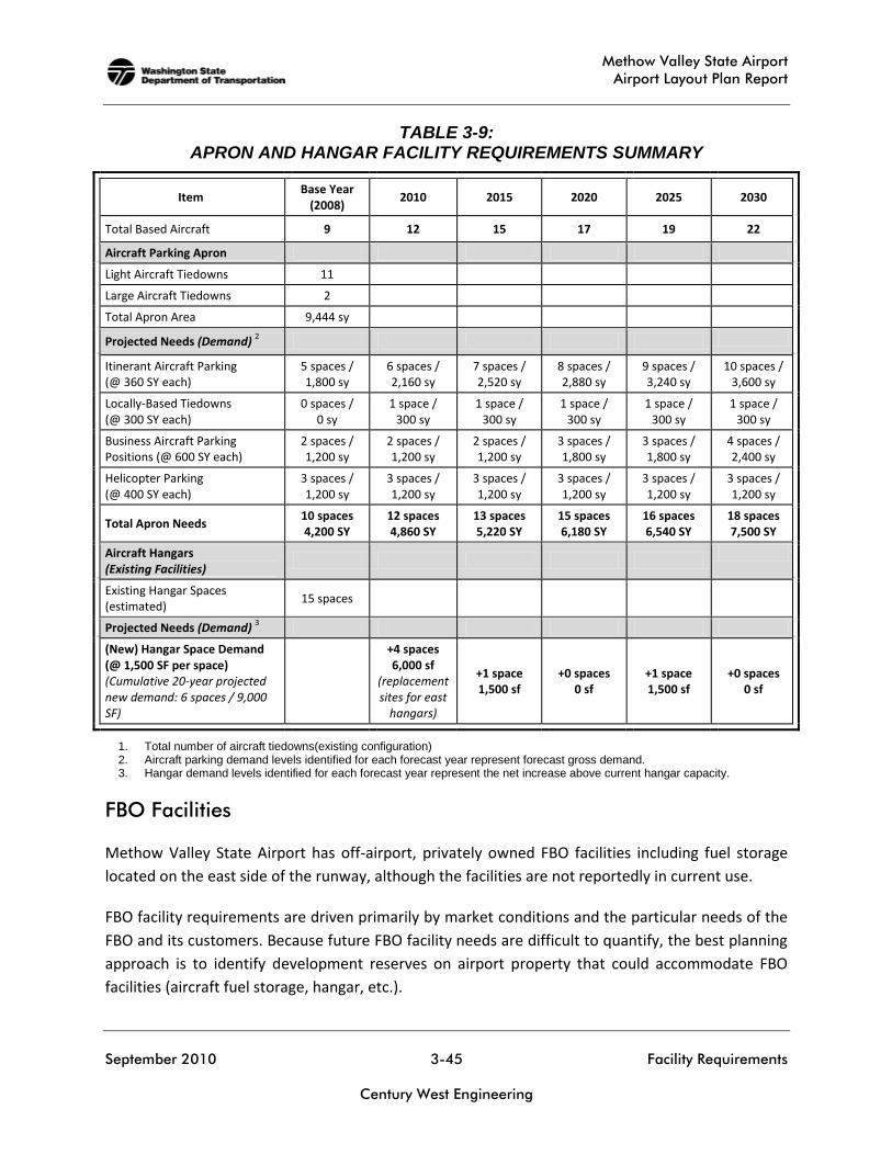
Methow Valley State Airport
Airport Layout Plan Report
September 2010 3-45 Facility Requirements
Century West Engineering
TABLE 3-9: APRON AND HANGAR FACILITY REQUIREMENTS SUMMARY
Item Base Year
(2008) 2010 2015 2020 2025 2030
Total Based Aircraft 9 12 15 17 19 22
Aircraft Parking Apron
Light Aircraft Tiedowns 11
Large Aircraft Tiedowns 2
Total Apron Area 9,444 sy
Projected Needs (Demand) 2
Itinerant Aircraft Parking (@ 360 SY each)
5 spaces / 1,800 sy
6 spaces / 2,160 sy
7 spaces / 2,520 sy
8 spaces / 2,880 sy
9 spaces / 3,240 sy
10 spaces / 3,600 sy
Locally-Based Tiedowns (@ 300 SY each)
0 spaces / 0 sy
1 space / 300 sy
1 space / 300 sy
1 space / 300 sy
1 space / 300 sy
1 space / 300 sy
Business Aircraft Parking Positions (@ 600 SY each)
2 spaces / 1,200 sy
2 spaces / 1,200 sy
2 spaces / 1,200 sy
3 spaces / 1,800 sy
3 spaces / 1,800 sy
4 spaces / 2,400 sy
Helicopter Parking (@ 400 SY each)
3 spaces / 1,200 sy
3 spaces / 1,200 sy
3 spaces / 1,200 sy
3 spaces / 1,200 sy
3 spaces / 1,200 sy
3 spaces / 1,200 sy
Total Apron Needs 10 spaces 4,200 SY
12 spaces 4,860 SY
13 spaces 5,220 SY
15 spaces 6,180 SY
16 spaces 6,540 SY
18 spaces 7,500 SY
Aircraft Hangars (Existing Facilities)
Existing Hangar Spaces (estimated)
15 spaces
Projected Needs (Demand) 3
(New) Hangar Space Demand (@ 1,500 SF per space) (Cumulative 20-year projected new demand: 6 spaces / 9,000 SF)
+4 spaces 6,000 sf
(replacement sites for east
hangars)
+1 space 1,500 sf
+0 spaces 0 sf
+1 space 1,500 sf
+0 spaces 0 sf
1. Total number of aircraft tiedowns(existing configuration) 2. Aircraft parking demand levels identified for each forecast year represent forecast gross demand. 3. Hangar demand levels identified for each forecast year represent the net increase above current hangar capacity.
FBO Facilities
Methow Valley State Airport has off-airport, privately owned FBO facilities including fuel storage
located on the east side of the runway, although the facilities are not reportedly in current use.
FBO facility requirements are driven primarily by market conditions and the particular needs of the
FBO and its customers. Because future FBO facility needs are difficult to quantify, the best planning
approach is to identify development reserves on airport property that could accommodate FBO
facilities (aircraft fuel storage, hangar, etc.).
Methow Valley State Airport
Airport Layout Plan Report
September 2010 3-46 Facility Requirements
Century West Engineering
Surface Access & Security Requirements
The existing surface access to the airport is provided by Evans Road (west side of runway) and Inter-
City Airport Road (east side of runway). In both cases, some changes in access may be needed to
address conflicts with runway protected areas or to effectively control traffic that inadvertently
enters the USFS smoke jumper base. The four hangars located on airport property on the east side
of the runway do not have dedicated vehicle access. Although these hangars have been planned for
relocation since 1991, current use creates access requirements for several tenants.
Adding fencing and vehicle gates should be considered to control unauthorized public access to the
airfield. The concrete barriers located near the end of Runway 31 are intended to prevent vehicles
from driving directly on the runway from Evans Road, which passes within 100 feet of the runway at
its nearest point. Some of the barriers are located within the runway safety area and do not meet
the FAA standard for frangibility. Replacement of the barriers with fencing mounted on frangible
posts should be considered.
Some overhead lighting is mounted on aircraft hangars; additional lighting is recommended to
illuminate new aprons and adjacent landside facilities.
SUPPORT FACILITIES
Aviation Fuel Storage
As noted in the inventory chapter, Methow Valley State Airport does not have aviation gasoline
(AVGAS) or jet fuel available for sale. The two privately owned fuel tanks are located off airport
property on the east side of the runway. The fueling area is located near the circular taxiway that is
located immediately north of the USFS complex. According to airport users, the tanks have not been
in use for several years. It is unknown whether the owner of the tanks intends to provide aviation
fuel for sale in the near future.
For planning purposes, a small fuel storage reserve should be identified on airport property,
adjacent to facilities used by itinerant aircraft. The airport may also want to discuss aviation fuel
storage needs with the USFS and the owner of the existing fuel tanks to identify possible long-term
options.
Airport Utilities
The airport has electrical power, with limited telephone and water service (wells) on the east side of
the runway. The airport has no sanitary sewer service, although the facilities on east side of the
runway utilize individual septic systems. The extension of electrical power on the west side of

Methow Valley State Airport
Airport Layout Plan Report
September 2010 3-47 Facility Requirements
Century West Engineering
airport (south of the apron) has been identified as an existing need to support seasonal (fire)
helicopter ground operations. Additional electrical extensions may be required to serve new
development or facilities (AWOS, lighting, etc.).
FACILITY REQUIREMENTS SUMMARY
The projected twenty-year facility needs for Methow Valley State Airport are summarized in Table
3-10. However, several other facility requirements needs are related to upgrading or replacing
existing facilities that do not meet FAA airport design standards.
TABLE 3-10: FACILITY REQUIREMENTS SUMMARY (ARC: A-II/B-II)
Item Short Term Long Term
Runway 13/31 Pavement Rehabilitation/ Maintenance
1
Obtain Clear Approaches and standard RSA, OFA, and OFZ
Pavement Maintenance1
Runway Extension Reserve
Taxiways/Taxilanes (Public Use Taxiways Only)
Pavement Maintenance1
Construct Taxiways/Taxilanes for new hangar areas, as needed
Pavement Maintenance1
Parallel Taxiway/Reserve
Construct Taxiways/Taxilanes for New Hangar Areas, as needed
Aircraft Aprons (Public Use Aprons Only)
Pavement Maintenance1
Reconfigure/Expand West Aircraft Apron to meet FAA Standards
Pavement Maintenance1
Development Reserves (fuel, tiedowns, etc.)
West Apron Expansion Reserve
Overlay West Apron
Hangars Develop Hangar Sites (market demand)
Remove/Relocate 4 hangars on east side of runway
Hangar Development Reserves
Navigational Aids Lighting, and Weather
Install PAPI
Replace MIRL
AWOS
GPS Approach (feasibility TBD)
Fuel Storage & FBO Facilities
Define Reserve for on-airport storage capacity
Same
Utilities Extend Electrical to new facilities
Water Improvements (fire protection) Same
Roadways & Vehicle Parking
Relocate/Reconfigure Evans Road to address safety issues
Extend internal access roads to new facilities; add vehicle parking
Extend internal access roads to new facilities; add vehicle parking
Security Airport Perimeter Fencing and Vehicle Gates
Flood Lighting Same
1. Vegetation control, crackfill, sealcoat