the 19th chesapeake sailing yacht symposium
TRANSCRIPT
Alpha and Rocker - Two Design Approaches that led to the Successful Challenge for the 2007 International C-Class Catamaran Championship Steve Killing, Steve Killing Yacht Design, Midland, Ontario, Canada
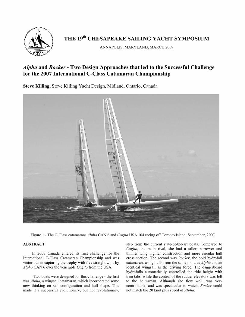
Figure 1 - The C-Class catamarans Alpha CAN 6 and Cogito USA 104 racing off Toronto Island, September, 2007 ABSTRACT
In 2007 Canada entered its first challenge for the
International C-Class Catamaran Championship and was victorious in capturing the trophy with five straight wins by Alpha CAN 6 over the venerable Cogito from the USA.
Two boats were designed for this challenge - the first
was Alpha, a wingsail catamaran, which incorporated some new thinking on sail configuration and hull shape. This made it a successful evolutionary, but not revolutionary,
step from the current state-of-the-art boats. Compared to Cogito, the main rival, she had a taller, narrower and thinner wing, lighter construction and more circular hull cross section. The second was Rocker, the bold hydrofoil catamaran, using hulls from the same mold as Alpha and an identical wingsail as the driving force. The daggerboard hydrofoils automatically controlled the ride height with trim tabs, while the control of the rudder elevators was left to the helmsman. Although she flew well, was very controllable, and was spectacular to watch, Rocker could not match the 20 knot plus speed of Alpha.
THE 19th CHESAPEAKE SAILING YACHT SYMPOSIUM ANNAPOLIS, MARYLAND, MARCH 2009
INTRODUCTION Early boats designed to the rule for the International
C-Class Catamaran Championship were sloop rigged catamarans, but by 1978 all boats in the competition carried wingsails. Amazing as today’s boats are, it is a great tribute to those early pioneers that Alpha, although faster, doesn’t look a lot different. The current developments are refinements in construction to reduce weight, in foil sections and wing philosophy to increase lift and reduce drag, and in hull shape to extend the top-end speed and retain control in heavy air.
As with all sailboat racing, the credit for this
successful challenge cannot rest solely with the design and construction of the boat. The C-Class catamaran is not an easy boat to sail, and preparation for a day of practice sailing can only be described as tedious. The hardsail does not roll up like a fabric sail - it must be stored in a ‘garage’ for the night and the sail and the mast are not independent -they must be raised up on the boat together. Fred Eaton and Magnus Clarke, Alpha’s crew, endured the long preparation time and continually experimented with hull-flying techniques, tacking efficiency, and downwind gybing angles until they knew what was best. Good technique combined with lighter weight gave them a marked edge in lighter airs, and sheer grunt work saw them through the heavy air races.
With C-Class cats being expensive, delicate,
complicated and somewhat nerve-racking to sail, they are not an abundant class. Nurturing new sailors for the cats is a careful process and the trade-off between hiding team secrets and freely divulging information must be weighed with care. Steve Clark, Duncan MacLane and David Hubbard, the brain trust behind Cogito, knew that in order for the class to survive they needed to have an “open house” attitude. They invited anyone with serious interest in the class to come for a visit. So on December 10, 2004, we learned what we could from Steve Clark and Cogito, in preparation for an event almost three years away. They were very generous in offering information, showing photos, having theoretical discussions and even holding the end of the tape measure during our inaugural visit to see their boat in Rhode Island. In order to continue that spirit of sharing which now pervades the class, we felt it appropriate to detail what we have learned from the Alpha program through this paper.
THE C-CLASS CATAMARAN CHALLENGE
The C-Class catamaran world is somewhat rarified -
not many players, not many newcomers at each event. But quantity has never been the target in the class - innovation, speed and more speed is what drives these sailors. In 2007 the Championship was won with a clean sweep by Canada’s Fred Eaton and Magnus Clarke sailing Alpha, in their first C-Class event.
None of the principal participants in the Canadian
program—project leader/skipper Fred Eaton, wingman Magnus Clarke, nor I, the chief designer—had ever sailed, designed, or even touched a C-Class cat prior to initiating this challenge for the C-Class Catamaran Championship. So our goal was modest: to create and sail a competitive C-Class cat, not necessarily to win the competition. It wasn’t until the beginning of the match race competition that we realized that Alpha and her crew had a real shot at beating Cogito, the formidable trophy holder from the US.
If you ask most designers what kind of project they
enjoy (and I include Fred and Magnus as key members of the all-Canadian design team), they will tell you it is the project with technical uncertainties that stretch the imagination, and the C-Class rules certainly leave ample room for imagination. Make a symmetrical catamaran that fits into a box 25 feet long, 14 feet wide, stick on 300 square feet of sail area and you will be legal. Any kind of sail, any hull shape, any weight, any material. A designer’s dream. Our lack of experience in the class led to a ‘science experiment’ approach to the design, construction, and sailing program. Whether it was strength of materials, hydrodynamics, aerodynamics, or sailing technique, the analysis was the same - calculate what you can, then test it, then refine it.
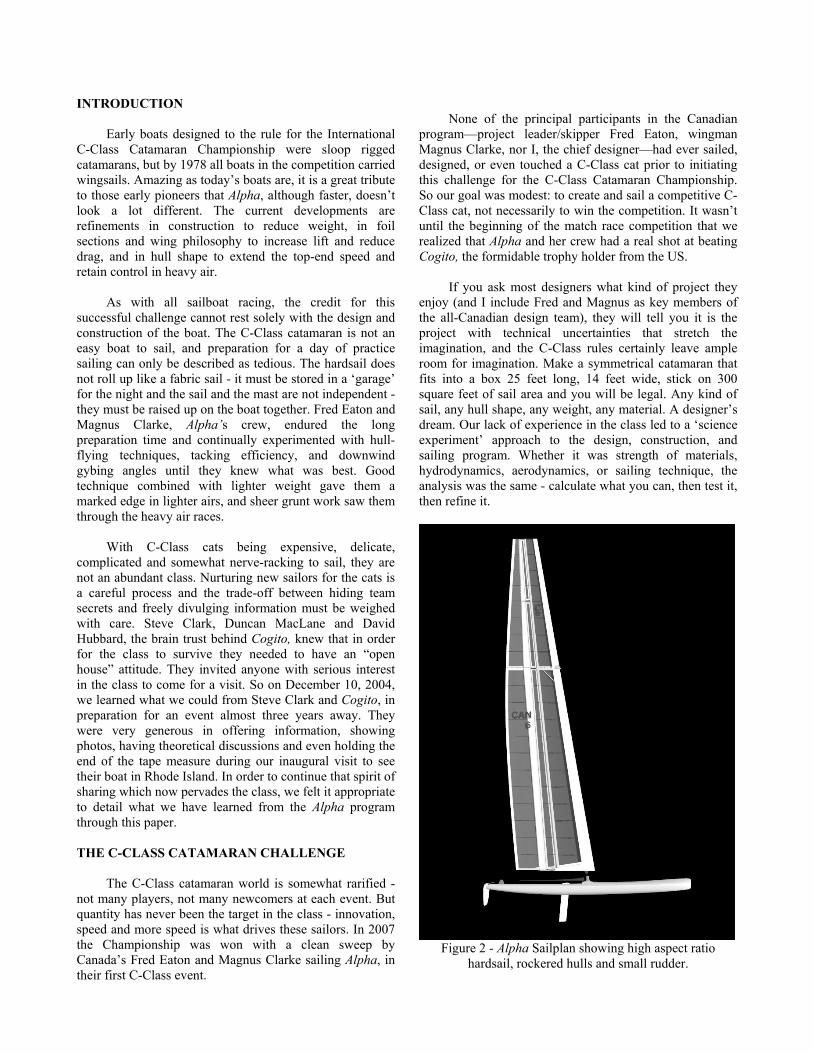
Figure 2 - Alpha Sailplan showing high aspect ratio
hardsail, rockered hulls and small rudder.
OVERALL PHILOSOPHY
From the outset we discussed a two boat campaign: one a conservative boat and a second that took aggressive design risks. The design of the radical boat (eventually built and called Off Yer Rocker) was set aside while we developed the safer, more sensible Alpha (if anything in the C-Class can be considered sensible). The design, construction, and sailing of Rocker will be discussed in the second half of this paper.
Since the championship was to be held near Perth,
Australia, we started to collect wind data, but soon decided that, because of the time and expense to be invested in the main boat, we couldn’t create a one-contest cat. Alpha needed to be an all-round performer up to the class’s competition wind speed limit of 20 knots. Our bias was to focus on one advantage we already had - a lightweight crew skilled at sailing in light airs (5-15 knots). As it turned out the event was eventually hosted in Toronto, Canada, and Alpha saw the full range of wind speeds.
Team Cogito had been particularly careful to
emphasize the importance of building the boat as light as prudently possible, noting that every pound cost several boat lengths over the course of a race. Those individual pounds added up quickly, and therefore every pound needed to serve a purpose. We were naively confident that with our design skills and the carbon composite experience of our builder, Multimatic Technical Centre, in Markham, Ontario, we could better the overall weight of Cogito, our prime competitor and the lightest C-cat ever built. As it turned out, Alpha weighed 360 pounds, compared to Cogito’s 383 pounds. In addition to the boat weight, our crew weight turned out to be approximately 30 pounds lower than Cogito’s, so on the light air days of the regatta we were sailing at a distinct advantage.
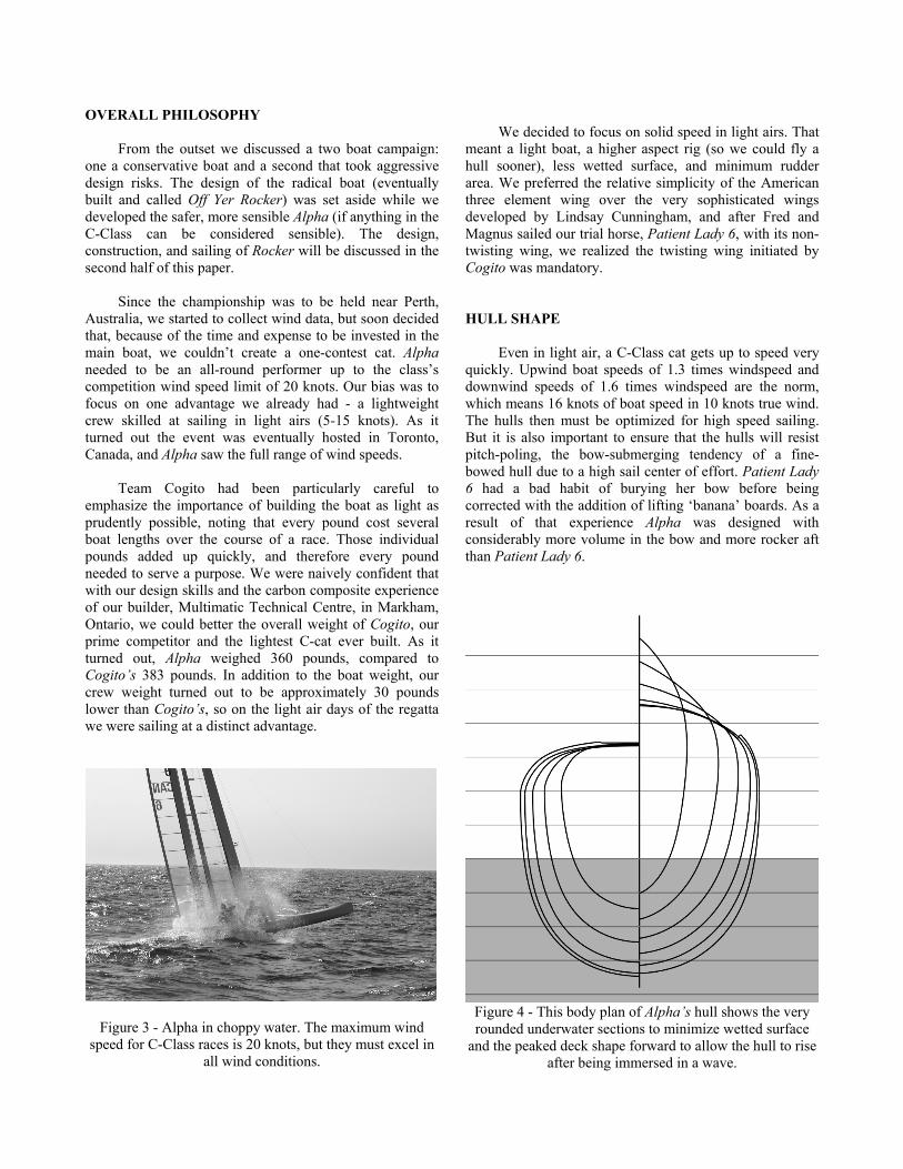
Figure 3 - Alpha in choppy water. The maximum wind speed for C-Class races is 20 knots, but they must excel in
all wind conditions.
We decided to focus on solid speed in light airs. That
meant a light boat, a higher aspect rig (so we could fly a hull sooner), less wetted surface, and minimum rudder area. We preferred the relative simplicity of the American three element wing over the very sophisticated wings developed by Lindsay Cunningham, and after Fred and Magnus sailed our trial horse, Patient Lady 6, with its non-twisting wing, we realized the twisting wing initiated by Cogito was mandatory.
HULL SHAPE
Even in light air, a C-Class cat gets up to speed very quickly. Upwind boat speeds of 1.3 times windspeed and downwind speeds of 1.6 times windspeed are the norm, which means 16 knots of boat speed in 10 knots true wind. The hulls then must be optimized for high speed sailing. But it is also important to ensure that the hulls will resist pitch-poling, the bow-submerging tendency of a fine-bowed hull due to a high sail center of effort. Patient Lady 6 had a bad habit of burying her bow before being corrected with the addition of lifting ‘banana’ boards. As a result of that experience Alpha was designed with considerably more volume in the bow and more rocker aft than Patient Lady 6.
Figure 4 - This body plan of Alpha’s hull shows the very rounded underwater sections to minimize wetted surface
and the peaked deck shape forward to allow the hull to rise after being immersed in a wave.
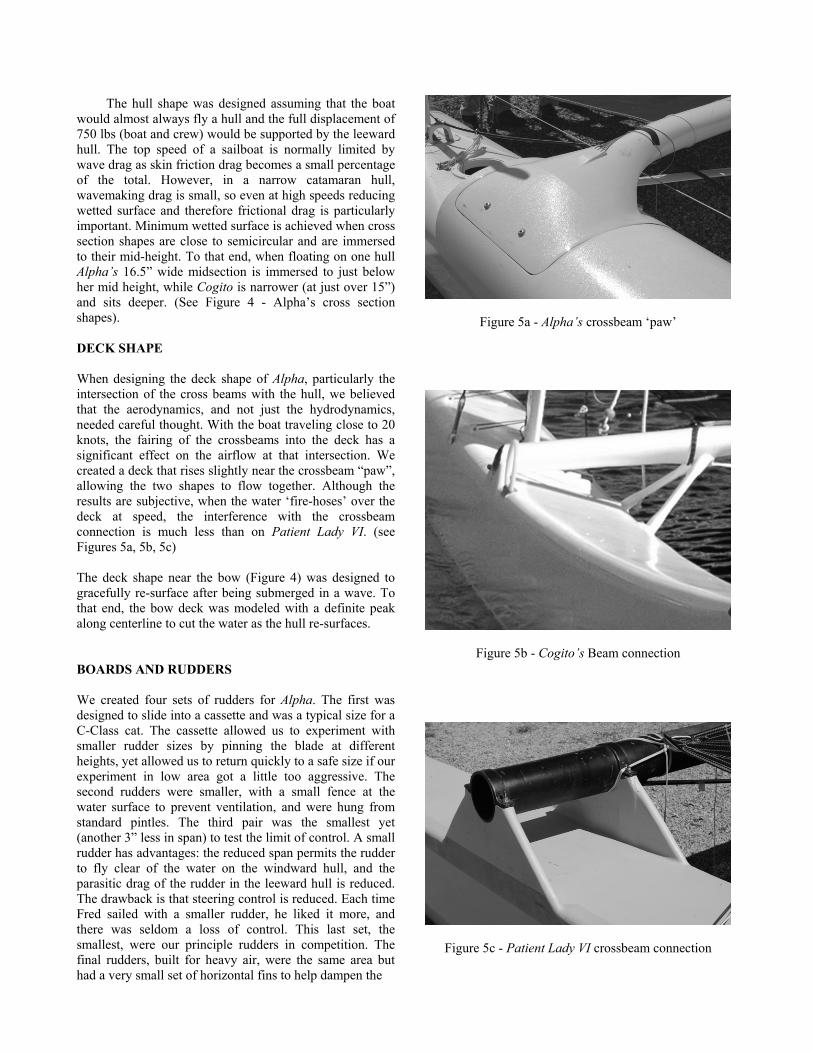
The hull shape was designed assuming that the boat would almost always fly a hull and the full displacement of 750 lbs (boat and crew) would be supported by the leeward hull. The top speed of a sailboat is normally limited by wave drag as skin friction drag becomes a small percentage of the total. However, in a narrow catamaran hull, wavemaking drag is small, so even at high speeds reducing wetted surface and therefore frictional drag is particularly important. Minimum wetted surface is achieved when cross section shapes are close to semicircular and are immersed to their mid-height. To that end, when floating on one hull Alpha’s 16.5” wide midsection is immersed to just below her mid height, while Cogito is narrower (at just over 15”) and sits deeper. (See Figure 4 - Alpha’s cross section shapes).
DECK SHAPE When designing the deck shape of Alpha, particularly the intersection of the cross beams with the hull, we believed that the aerodynamics, and not just the hydrodynamics, needed careful thought. With the boat traveling close to 20 knots, the fairing of the crossbeams into the deck has a significant effect on the airflow at that intersection. We created a deck that rises slightly near the crossbeam “paw”, allowing the two shapes to flow together. Although the results are subjective, when the water ‘fire-hoses’ over the deck at speed, the interference with the crossbeam connection is much less than on Patient Lady VI. (see Figures 5a, 5b, 5c) The deck shape near the bow (Figure 4) was designed to gracefully re-surface after being submerged in a wave. To that end, the bow deck was modeled with a definite peak along centerline to cut the water as the hull re-surfaces. BOARDS AND RUDDERS
We created four sets of rudders for Alpha. The first was designed to slide into a cassette and was a typical size for a C-Class cat. The cassette allowed us to experiment with smaller rudder sizes by pinning the blade at different heights, yet allowed us to return quickly to a safe size if our experiment in low area got a little too aggressive. The second rudders were smaller, with a small fence at the water surface to prevent ventilation, and were hung from standard pintles. The third pair was the smallest yet (another 3” less in span) to test the limit of control. A small rudder has advantages: the reduced span permits the rudder to fly clear of the water on the windward hull, and the parasitic drag of the rudder in the leeward hull is reduced. The drawback is that steering control is reduced. Each time Fred sailed with a smaller rudder, he liked it more, and there was seldom a loss of control. This last set, the smallest, were our principle rudders in competition. The final rudders, built for heavy air, were the same area but had a very small set of horizontal fins to help dampen the
Figure 5a - Alpha’s crossbeam ‘paw’
Figure 5b - Cogito’s Beam connection
Figure 5c - Patient Lady VI crossbeam connection
pitching motion of the boat. They proved key on the final day of competition, allowing the crew to push the boat a little harder downwind in high wind and waves.
C-Class cats spend most of their time sailing on one
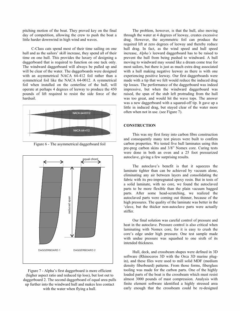
hull and as the sailors’ skill increase, they spend all of their time on one hull. This provides the luxury of designing a daggerboard that is required to function on one tack only. The windward daggerboard will always be pulled up and will be clear of the water. The daggerboards were designed with an asymmetrical NACA 64-412 foil rather than a symmetrical foil like the NACA 64-0012. A symmetrical foil when installed on the centerline of the hull, will operate at perhaps 4 degrees of leeway to produce the 450 pounds of lift required to resist the side force of the hardsail.
Figure 6 - The asymmetrical daggerboard foil
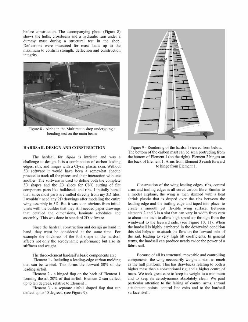
Figure 7 - Alpha’s first daggerboard is more efficient (higher aspect ratio and reduced tip loss), but lost out to
daggerboard 2. The second daggerboard of equal area pulls up further into the windward hull and makes less contact
with the water when flying a hull.
The problem, however, is that the hull, also moving through the water at 4 degrees of leeway, creates excessive drag. However, the asymmetric foil can produce the required lift at zero degrees of leeway and thereby reduce hull drag. In fact, as the wind speed and hull speed increase, Alpha’s leeward daggerboard has to be raised to prevent the hull from being pushed to windward. A hull moving to windward may sound like a dream come true for most sailors, but there is just as much extra drag associated with a hull making negative leeway as there is with one experiencing positive leeway. Our first daggerboards were made with a tip that we felt would reduce the induced drag tip losses. The performance of the daggerboard was indeed impressive, but when the windward daggerboard was raised, the span of the stub left protruding from the hull was too great, and would hit the wave tops. The answer was a new daggerboard with a squared-off tip. It gave up a little in induced drag, but stayed clear of the water more often when not in use. (see Figure 7).
CONSTRUCTION This was my first foray into carbon fibre construction
and consequently many test pieces were built to confirm carbon properties. We tested five hull laminates using thin pre-preg carbon skins and 3/8” Nomex core. Curing tests were done in both an oven and a 25 foot pressurized autoclave, giving a few surprising results.
The autoclave’s benefit is that it squeezes the
laminate tighter than can be achieved by vacuum alone, eliminating any air between layers and consolidating the fabric with its pre-impregnated epoxy resin. But in tests of a solid laminate, with no core, we found the autoclaved parts to be more flexible than the plain vacuum bagged parts. After some head-scratching, we realized the autoclaved parts were coming out thinner, because of the high pressures. The quality of the laminate was better in the ‘clave, but the thicker non-autoclave parts were actually stiffer.
Our final solution was careful control of pressure and
heat in the autoclave. Pressure control is also critical when laminating with Nomex core, for it is easy to crush the core’s edge under high pressure. One test sample made with undue pressure was squashed to one sixth of its intended thickness.
Hull, deck, and crossbeam shapes were defined in 3D
software (Rhinoceros 3D with the Orca 3D marine plug-in), and these files were used to mill solid MDF (medium density fiberboard) patterns. From those forms, fiberglass tooling was made for the carbon parts. One of the highly loaded parts of the boat is the crossbeam which must resist almost 3000 pounds of mast compression. Analysis with finite element software identified a highly stressed area early enough that the crossbeam could be re-designed
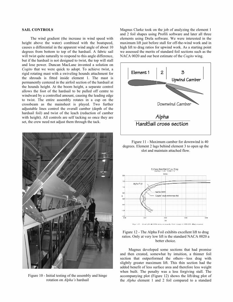
before construction. The accompanying photo (Figure 8) shows the hulls, crossbeam and a hydraulic ram under a dummy mast during a structural test in the shop. Deflections were measured for mast loads up to the maximum to confirm strength, deflection and construction integrity.
Figure 8 - Alpha in the Multimatic shop undergoing a
bending test on the main beam
HARDSAIL DESIGN AND CONSTRUCTION
The hardsail for Alpha is intricate and was a
challenge to design. It is a combination of carbon leading edges, ribs, and hinges with a Clysar plastic skin. Without 3D software it would have been a somewhat chaotic process to track all the pieces and their interaction with one another. The software is used to define both the complete 3D shapes and the 2D slices for CNC cutting of flat component parts like bulkheads and ribs. I initially hoped that, since most parts are milled directly from my 3D files, I wouldn’t need any 2D drawings after modeling the entire wing assembly in 3D. But it was soon obvious from initial visits with the builder that they still needed paper drawings that detailed the dimensions, laminate schedules and assembly. This was done in standard 2D software.
Since the hardsail construction and design go hand in
hand, they must be considered at the same time. For example the thickness of the foil shape in the hardsail affects not only the aerodynamic performance but also its stiffness and weight.
The three-element hardsail’s basic components are: Element 1 - Including a leading-edge carbon molding
that can be twisted. This forms the forward 80% of the leading airfoil.
Element 2 - a hinged flap on the back of Element 1 forming the aft 20% of that airfoil. Element 2 can deflect up to ten degrees, relative to Element 1
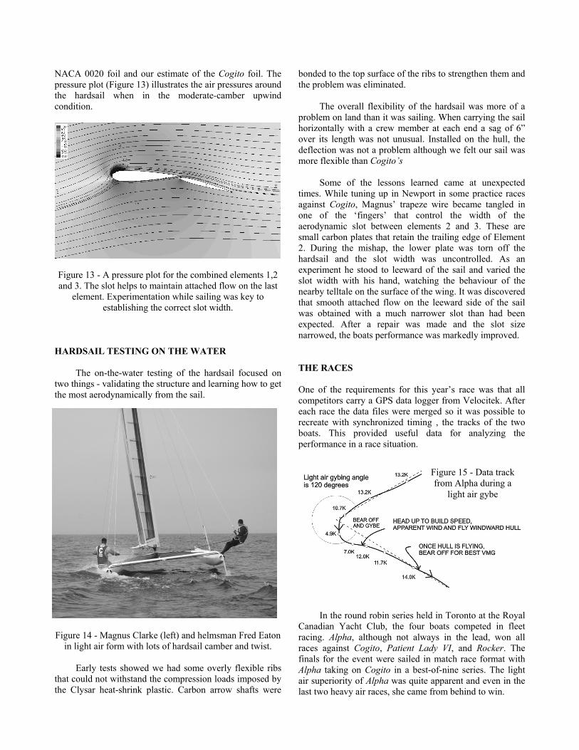
Element 3 - a separate airfoil shaped flap that can deflect up to 40 degrees. (see Figure 9).
Figure 9 - Rendering of the hardsail viewed from below. The bottom of the carbon mast can be seen protruding from the bottom of Element 1 (on the right). Element 2 hinges on the back of Element 1. Arms from Element 3 reach forward
to hinge from Element 1.
Construction of the wing leading edges, ribs, control
arms and trailing edges is all cored carbon fibre. Similar to a model airplane, the wing is then skinned with a heat shrink plastic that is draped over the ribs between the leading edge and the trailing edge and taped into place, to create a smooth yet flexible wing surface. Between elements 2 and 3 is a slot that can vary in width from zero to about one inch to allow high-speed air through from the windward to the leeward side. (see Figure 10, 11). When the hardsail is highly cambered in the downwind condition this slot helps to re-attach the flow on the leeward side of the sail, leading to very high lift coefficients. In general terms, the hardsail can produce nearly twice the power of a fabric sail.
Because of all its structural, moveable and controlling
components, the wing necessarily weighs almost as much as the hull platform. This has drawbacks relating to both a higher mass than a conventional rig, and a higher centre of mass. We took great care to keep its weight to a minimum and to keep its aerodynamics absolutely clean. We paid particular attention to the fairing of control arms, shroud attachment points, control line exits and to the hardsail surface itself.
SAIL CONTROLS The wind gradient (the increase in wind speed with
height above the water) combined with the boatspeed, causes a differential in the apparent wind angle of about 10 degrees from bottom to top of the hardsail. A fabric sail will twist quite naturally to respond to this angle difference, but if the hardsail is not designed to twist, the top will stall and lose power. Duncan MacLane invented a solution on Cogito that we were quick to adopt. To achieve twist, a rigid rotating mast with a swiveling hounds attachment for the shrouds is fitted inside element 1. The mast is permanently centered in the airfoil section of the hardsail at the hounds height. At the boom height, a separate control allows the foot of the hardsail to be pulled off centre to windward by a controlled amount, causing the leading edge to twist. The entire assembly rotates in a cup on the crossbeam as the mainsheet is played. Two further adjustable lines control the overall camber (depth of the hardsail foil) and twist of the leach (reduction of camber with height). All controls are self tacking so once they are set, the crew need not adjust them through the tack.
Figure 10 - Initial testing of the assembly and hinge rotation on Alpha’s hardsail
Magnus Clarke took on the job of analyzing the element 1 and 2 foil shapes using Profili software and later all three elements using Drela software. We were interested in the maximum lift just before stall for off-the-wind work and in high lift to drag ratios for upwind work. As a starting point we assessed the merits of standard foil sections such as the NACA 0020 and our best estimate of the Cogito wing.
Figure 11 - Maximum camber for downwind is 40 degrees. Element 2 lags behind element 3 to open up the
slot and maintain attached flow.
Figure 12 - The Alpha Foil exhibits excellent lift to drag ratios. Only at very low lift is the standard NACA 0020 a
better choice. Magnus developed some sections that had promise
and then created, somewhat by intuition, a thinner foil section that outperformed the others—less drag with slightly greater maximum lift. This thin section had the added benefit of less surface area and therefore less weight when built. The penalty was a less forgiving stall. The accompanying plot (Figure 12) shows the lift/drag plot of the Alpha element 1 and 2 foil compared to a standard
NACA 0020 foil and our estimate of the Cogito foil. The pressure plot (Figure 13) illustrates the air pressures around the hardsail when in the moderate-camber upwind condition.
Figure 13 - A pressure plot for the combined elements 1,2 and 3. The slot helps to maintain attached flow on the last
element. Experimentation while sailing was key to establishing the correct slot width.
HARDSAIL TESTING ON THE WATER
The on-the-water testing of the hardsail focused on
two things - validating the structure and learning how to get the most aerodynamically from the sail.
Figure 14 - Magnus Clarke (left) and helmsman Fred Eaton
in light air form with lots of hardsail camber and twist. Early tests showed we had some overly flexible ribs
that could not withstand the compression loads imposed by the Clysar heat-shrink plastic. Carbon arrow shafts were
bonded to the top surface of the ribs to strengthen them and the problem was eliminated.
The overall flexibility of the hardsail was more of a
problem on land than it was sailing. When carrying the sail horizontally with a crew member at each end a sag of 6” over its length was not unusual. Installed on the hull, the deflection was not a problem although we felt our sail was more flexible than Cogito’s
Some of the lessons learned came at unexpected times. While tuning up in Newport in some practice races against Cogito, Magnus’ trapeze wire became tangled in one of the ‘fingers’ that control the width of the aerodynamic slot between elements 2 and 3. These are small carbon plates that retain the trailing edge of Element 2. During the mishap, the lower plate was torn off the hardsail and the slot width was uncontrolled. As an experiment he stood to leeward of the sail and varied the slot width with his hand, watching the behaviour of the nearby telltale on the surface of the wing. It was discovered that smooth attached flow on the leeward side of the sail was obtained with a much narrower slot than had been expected. After a repair was made and the slot size narrowed, the boats performance was markedly improved.
THE RACES
One of the requirements for this year’s race was that all competitors carry a GPS data logger from Velocitek. After each race the data files were merged so it was possible to recreate with synchronized timing , the tracks of the two boats. This provided useful data for analyzing the performance in a race situation.
In the round robin series held in Toronto at the Royal
Canadian Yacht Club, the four boats competed in fleet racing. Alpha, although not always in the lead, won all races against Cogito, Patient Lady VI, and Rocker. The finals for the event were sailed in match race format with Alpha taking on Cogito in a best-of-nine series. The light air superiority of Alpha was quite apparent and even in the last two heavy air races, she came from behind to win.
Figure 15 - Data track from Alpha during a
light air gybe
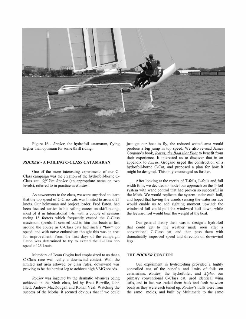
Figure 16 - Rocker, the hydrofoil catamaran, flying higher than optimum for some thrill riding.
ROCKER - A FOILING C-CLASS CATAMARAN
One of the more interesting experiments of our C-
Class campaign was the creation of the hydrofoil-borne C-Class cat, Off Yer Rocker (an appropriate name on two levels), referred to in practice as Rocker.
As newcomers to the class, we were surprised to learn
that the top speed of C-Class cats was limited to around 23 knots. Our helmsman and project leader, Fred Eaton, had been focused earlier in his sailing career on skiff racing, most of it in International 14s, with a couple of seasons racing 18 footers which frequently exceed the C-Class maximum speeds. It seemed odd to him that boats as fast around the course as C-Class cats had such a “low” top speed, and with naïve enthusiasm thought this was an area for improvement. From the first days of the campaign, Eaton was determined to try to extend the C-Class top speed of 23 knots.
Members of Team Cogito had emphasized to us that a
C-Class race was really a downwind contest. With the limited sail area allowed by class rules, downwind was proving to be the hardest leg to achieve high VMG speeds.
Rocker was inspired by the dramatic advances being
achieved in the Moth class, led by Brett Burville, John Illett, Andrew MacDougall and Rohan Veal. Watching the success of the Moths, it seemed obvious that if we could
just get our boat to fly, the reduced wetted area would produce a big jump in top speed. We also re-read James Grogano’s book, Icarus, the Boat that Flies to benefit from their experience. It interested us to discover that in an appendix to Icarus, Grogano urged the construction of a hydrofoil-borne C-Cat, and proposed a plan for how it might be designed. This only encouraged us further.
After looking at the merits of T-foils, L-foils and full
width foils, we decided to model our approach on the T-foil system with wand control that had proven so successful in the Moth. We would replicate the system under each hull, and hoped that having the wands sensing the water surface would enable us to add righting moment upwind: the windward foil could pull the windward hull down, while the leeward foil would bear the weight of the boat.
Our general theory then, was to design a hydrofoil
that could get to the weather mark soon after a conventional C-Class cat, and then pass them with dramatically improved speed and direction on downwind legs.
THE ROCKER CONCEPT
Our experiment in hydrofoiling provided a highly controlled test of the benefits and limits of foils on catamarans. Rocker, the hydrofoiler, and Alpha, our primary conventional C-Class cat, used identical wing sails, and in fact we traded them back and forth between boats as they were each tuned up. Rocker’s hulls were from the same molds, and built by Multimatic to the same
careful standards they had used in Alpha. If anything, Rocker was better built as a result of the experience gained building Alpha.
In the initial design stages, we found there were an overwhelming number of unknowns and subjective decisions to be made.
- At what speed should we design the boat to take off? Large foils would get us flying early, but would pay a drag penalty at high speeds.
- How high a lift coefficient should we expect to get from the foils? We knew the theory, but what would the tip losses be on the foil, and the losses due to imperfections in the foil surface?
- How could we determine the dynamic response of the boat when flying? Could we ask the helmsman to fly the boat or would an automatic system be better?
- What were the dynamic loads? We could calculate the static loads, but how strong did the hydrofoils need to be for the dynamic loads?
It was hard to know which decisions to make first,
and some sailors have asked us why we didn’t tank-test the boat before we committed to building. The answer was that the cost and time required to tank-test a full-size model of the boat is about the same as that required to build and sail the real boat, thus the building of the boat was truly our full-size tank-test. Tank testing has the advantage of being able to isolate various parts, eliminating the effect of the helmsman or the influence of the wave state for example, but in this case the interaction of the parts and the dynamics of the entire boat were critical and needed to be included. So we felt it important that the analysis of the complete boat be done on the water. The acceptance by our
entire team of the Rocker program as a complicated science experiment was critical. It removed the pressure for success on the first try, and freed the mind to dabble in the unknown. When the science was not available to provide a definitive answer, then a considered estimate was an honorable choice.
The initial analysis of whether we could make speed
gains was done with the help of the WinDesign VPP software. This software tool is adequate for analyzing standard monohulls and multihulls, but with a foiling C-Class cat, the software’s lift and drag characteristics for the sailplan had to be replaced with estimates of those for the multi-element hardsail, and the VPP’s hull model was replaced with the hydrofoil’s lift and drag. We tried to be pessimistic on all counts and yet the speed gains still indicated a couple of knots of improvement, giving us the confidence to move ahead.
Rocker was raced by 49er sailors Dan Cunningham
and Rob Paterson, who had proven in 2006 that they could race our trial horse, Patient Lady VI, competitively against Cogito and Alpha. If Rocker failed, it would not be due to the construction, crew, or the power plant.
HULLS The hulls on a hydrofoiler need only be of sufficient
volume to keep the boat from sinking, and long enough to allow the boat to comfortably achieve lift-off speed. For a C-Class that length is well under the 25 feet allowed by the class. We had initially considered building shorter hulls for
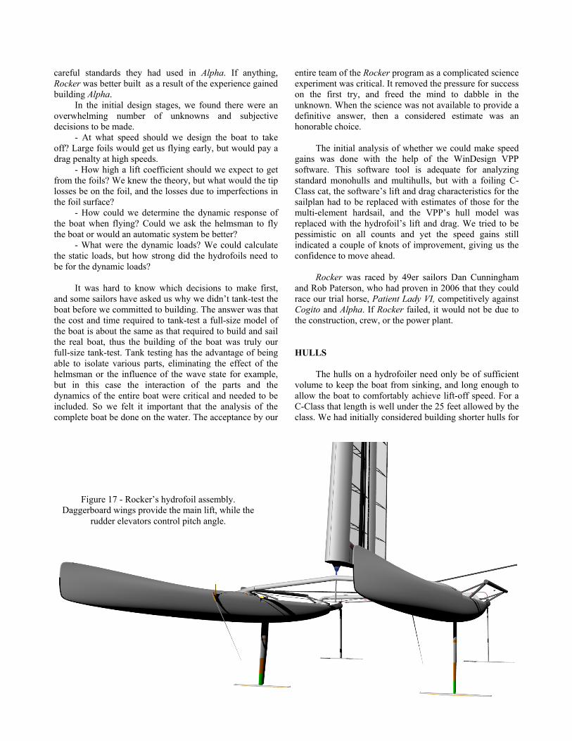
Figure 17 - Rocker’s hydrofoil assembly. Daggerboard wings provide the main lift, while the
rudder elevators control pitch angle.

Rocker in order to save weight, but ultimately we chose to use the same hull shapes as Alpha, thus avoiding the cost of new molds, and maintaining long bows for landing in the event of foil ventilation. All hydrofoil boats seem to lose control eventually, whether due to crew inattention or (as Rocker did on several days of training) flying too high in strong winds. We needed a sufficiently long platform to ensure the hardsail stayed upright when we landed. Capsizing with a carbon and heat-shrink plastic hardsail is not just the end of the day’s sailing, but at best, means several days of carbon repair, and at worst, the end of a campaign. A shorter hull length might have improved lift-off by saving ten pounds, but it was not worth the risk.
Transverse stability of a C-Cat is limited by the class
rule of a maximum beam of 14 feet. But since all components of the boat have to fit within this width and foils extend laterally beyond the deck edge, the hulls of the foiling Rocker had to be positioned more closely together than those of Alpha. Once foil-borne, fore and aft stability as well as steering sensitivity is related to the foil “wheelbase”—the fore and aft separation of the foils on the daggerboards and rudders. Since we were using the standard hull and deck from Alpha, our crossbeam locations were fixed, and that caused some concern. With the forward crossbeam and therefore the hardsail’s position locked, to keep helm balance reasonable the daggerboard could not stray from the location we had on Alpha, 9 feet forward of the transom. The separation between rudder elevator and daggerboard wing was therefore short. Our hunch was that the boat would be much too sensitive at speed.
Figure 18 - Rob Paterson and Dan Cunningham keep
Rocker four-point foiling in light air. To gain adequate separation between the underwater
foils we added carbon “exhaust pipes” out the transom – a stretch of the class rules, but technically legal as we read them. Since the rudders hang off the back end of these extensions they had to be stiff in bending and torsion. Some Finite Element analysis was performed to find the most efficient way to support the rudders and that investigation changed our thinking from the initial plan of a multi-tube truss to the single 33” long by 5” diameter carbon tubes.
FOILS A quick look at some historic foiling vessels
illustrates the range of possible foiling arrangements – surface-piercing vee-foils, ladder foils, submerged T-foils, L-foils, and full-width foils. In our assessment the surface-piercing options have too much associated spray drag and loss of lift, although the fact that they are self-adjusting in height was attractive. Submerged foils have better lift characteristics and less spray drag, but the immersed depth is difficult to control and their structure is more challenging to build. Since this project was all about speed and efficiency, the benefits of the submerged foils overshadowed any challenges they added.
Full-width foils that stretch between the two
daggerboards were tempting from a structural standpoint, but we wanted to be able to decouple the port and starboard underwater wings. That is, we wanted to be able to shift the lift all to port or all to starboard. If this is not done and the lift is equal on both hulls, the stability of the catamaran is significantly reduced.
The final decision of T-foil versus L-shaped foil came
down to structure. Our final choice of the T-foil allowed us to have a smaller joint between the horizontal hydrofoil and the vertical rudder or daggerboard (we went with the same solution for both control surfaces).
The vertical foil shapes for the rudder and
daggerboard were different as they were chosen for different purposes. The daggerboard in Alpha was an asymmetrical section chosen to limit the leeway and therefore the drag of the hull. In Rocker, the take-off from displacement sailing to hydrofoil flying was expected to occur with all four foils in the water. Consequently, asymmetrical sections on both port and starboard daggerboards would simply try to squeeze the hulls together. Instead we chose a symmetrical NACA 63-012 for Rocker, which has low drag at low angles of attack from speeds of 5 to 25 knots. The rudder, however, can see higher angles of attack as the helmsman aggressively steers the boat and there we used the NACA 0012 foil, which has less drag at higher angles and a more gradual stall.
The main daggerboard wing area was chosen to fly
the hull at a minimum of 8 knots. At 1.67 square feet for each daggerboard wing, take-off requires a lift coefficient of 1.25, dangerously close to stall, while takeoff at 10 knots only requires a coefficient of 0.75. Although the 10 knot takeoff requirement is easily achievable before stall with our chosen foil section (a modified Selig 3010), the hinged flap making up the last 25% of the foil can boost the lift to make an 8 knot take-off possible. Having a flap which controls the lift means ride height can be regulated as speed increases, without which the boat would continue to rise and fly out of the water (which did happen on occasion).
The above foil-size considerations were all done assuming the daggerboards alone are doing all the lifting, with none coming from the rudders. In fact, depending on the situation, Rocker’s rudders are at times producing negative (that is downward) lift, such as at take off in order to raise the bows and increase the angle of attack of the daggerboard foils. Suffice to say that this part of the theory seemed to work. The boat can take off and begin to fly at 8 knots of boat speed.
A quick check in a reference text like Theory of Wing
Sections by Abbott and Von Doenhoff shows that in order for a wing to maintain a reasonable lift to drag ratio, the aspect ratio should be above 5, and the higher the better. Long, skinny wings are very efficient. The daggerboard wing has an aspect ratio of 6.6 with a span of 44” and as such protrudes past the outboard edge of the hulls. As noted, this required a shortening of the main crossbeam at the design stage to keep the outboard tips of the wings within the class limit of 14 feet maximum allowable beam.
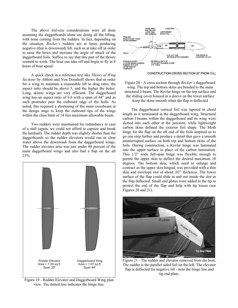
Two rudders were maintained for redundancy in case
of a stall (again, we could not afford to capsize and break the hardsail). The rudder depth was slightly shorter than the daggerboards so the rudder elevators would run in clear water above the downwash from the daggerboard wings. The rudder elevator area was just under 80 percent of the main daggerboard wings and also had a flap on the aft 23%.
Figure 19 - Rudder Elevator and Daggerboard Wing plan
view. The dotted line indicates the hinge line.
Figure 20 - A cross section through Rocker’s daggerboard wing. The top and bottom skins are bonded to the main
structural I-beam. The Kevlar hinge on the top surface and the sliding cover housed in a sleeve on the lower surface
keep the skins smooth when the flap is deflected The daggerboard vertical foil was tapered in chord
length as it terminated at the daggerboard wing. Structural carbon I-beams within the daggerboard and its wing were slotted into each other at the junction, while lightweight carbon skins defined the exterior foil shape. The Moth hinge for the flap on the aft end of the foils inspired us to go one step further and produce a detail that gave a smooth uninterrupted surface on both top and bottom skins of the foils. During construction, a Kevlar hinge was laminated into the upper surface in place of the carbon lamination. This 1/2” wide full-span hinge was flexible enough to permit the upper skin to deflect the desired maximum 10 degrees. The bottom skin, which need to enlarge and contract as the upper skin hinged, was provided with a thin skin and envelope slot of about .02” thickness. The lower surface of the flap could slide in and out inside the slot as the flap deflected. Small end plates were added to the tip to protect the end of the flap and help with tip losses (see Figures 20 and 21).
Figure 21 - The rudder and elevator removed from the boat. The rudder is the parallel sided foil on the left. The elevator
flap is deflected for negative lift - note the hinge line and tip end plate.
CONTROLS The now-common practice of CNC cutting of sheet
material makes the creation of parts like the wand driving mechanism quite practical (although for some pieces the shape was so simple that the builder simply glued the drawing straight to a carbon plate and cut it out by hand). Rocker’s wand control is modeled after the system developed for the Moth. The wand’s job is to control the ride height. When the boat is too low, the wand rotates aft, which pushes on the control cable and deflects the flap downwards on the daggerboard wing to raise the boat. If the wand is too far from the daggerboard then it will get a false reading. For example if the ride height is already optimum (the daggerboard is exposed about 12”), but the bow is raised, a wand mounted forward on the hull would indicate the hull is too high and reduce the flap angle—not the desired response. Our wand pivot is six feet forward of the wing that it controls. With a long hull forward of the daggerboard we had complete freedom as to where the wand should be. The initial location we chose proved suitable and was never changed.
After talking over several control techniques, we decided to give the rudder elevator control to the helmsman. The dynamics between the rudder elevators and the daggerboard wings were unknown, and while we didn’t want to increase the helmsman’s tasks, it seemed like the best solution. It turned out that Eaton could easily control the elevators and thereby the hull trim angle. We used double tiller extensions leading into a tiller-mounted gearbox to provide the manual pitch control through the elevator flaps.
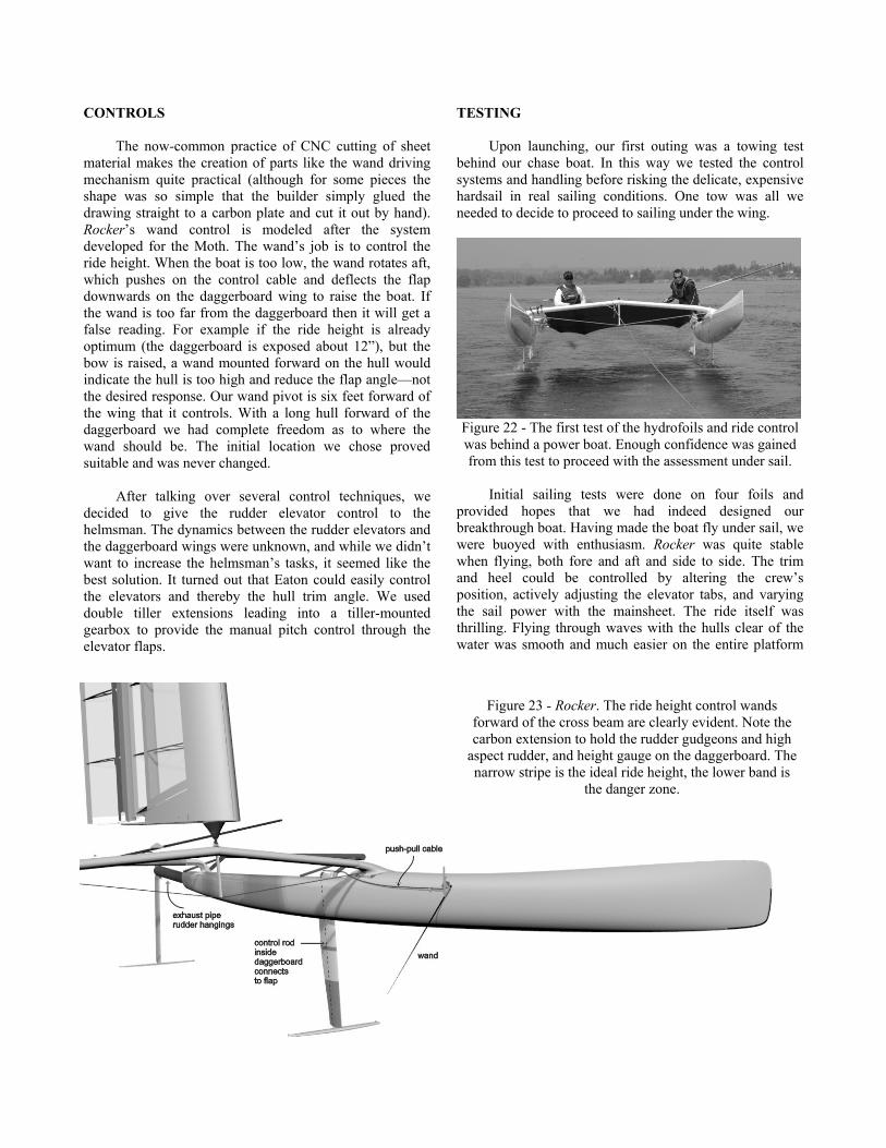
TESTING Upon launching, our first outing was a towing test
behind our chase boat. In this way we tested the control systems and handling before risking the delicate, expensive hardsail in real sailing conditions. One tow was all we needed to decide to proceed to sailing under the wing.
Figure 22 - The first test of the hydrofoils and ride control was behind a power boat. Enough confidence was gained from this test to proceed with the assessment under sail.
Initial sailing tests were done on four foils and
provided hopes that we had indeed designed our breakthrough boat. Having made the boat fly under sail, we were buoyed with enthusiasm. Rocker was quite stable when flying, both fore and aft and side to side. The trim and heel could be controlled by altering the crew’s position, actively adjusting the elevator tabs, and varying the sail power with the mainsheet. The ride itself was thrilling. Flying through waves with the hulls clear of the water was smooth and much easier on the entire platform
Figure 23 - Rocker. The ride height control wands forward of the cross beam are clearly evident. Note the carbon extension to hold the rudder gudgeons and high
aspect rudder, and height gauge on the daggerboard. The narrow stripe is the ideal ride height, the lower band is
the danger zone.
than Alpha, as there was no racking (the raising of one bow relative to the other). Sailing the boat was eerily quiet, and although there was no trial horse alongside, Rocker seemed fast.
The wand control system did its job, more or less,
although it seemed we always needed more lift. Pulling in the mainsheet for more driving force would drive the foils back down into the water rather than speed the boat up. Later work proved that our best results occurred when we were footing. We could at times get the boat up to speed, but could not match Alpha in upwind sailing.
In an attempt to reduce drag and boost upwind speed,
we tested for several days using only three foils in the boat – one daggerboard and two rudders. Rocker flew only once on three foils and while she seemed impressive while doing so, we could never repeat the success. Three foils produced slightly better windward performance, but downwind, the inability to “foil” left it as a losing strategy for racing around the course.
To achieve stability close to a conventional C-Class
cat, two foil sailing has to be achieved. The windward daggerboard and its wing need to be lifted out of the water, or its flap angle adjusted to get zero lift. Otherwise, the windward foil is lifting the windward hull and negating the benefit of the crew on the trapeze. Adjusting the flap angle to zero lift still left a large surface area of foils dragging through the water, and was not a good solution. Lifting the foil out of the water on each tack, although theoretically beneficial, was never mastered with any level of finesse and could not be done quickly while racing. Since we also needed to attach and detach the control systems for the flaps, it was ponderously slow. In addition, the benefits were limited, as the weather foil would slap the passing wave surfaces. The attempt was abandoned after one race, and Rocker carried on competing on four foils. It is worth repeating that the huge detriment to four-foil sailing is the loss in stability from that normally associated with multihull sailing. Four-foil hydrofoiling results in the same stability as a narrow monohull.
A month before the International C-Class
Championship, we had exhausted all ideas of how to get Rocker up to speed, but Rohan Veal was in America promoting Bladerider Moths. We invited him up to Toronto, to see if we were missing something important in the way we were sailing the boat, or in its setup. We had a very productive day with him that led to the re-pitching of our main wings, adding 3 degrees to their permanent angle of attack. The boat did perform better thereafter, but it was still a long way from being competitive. The week before the event we added some trapezing racks onto the hulls to get back some of the righting moment we had lost due to the reduced beam of the boat.
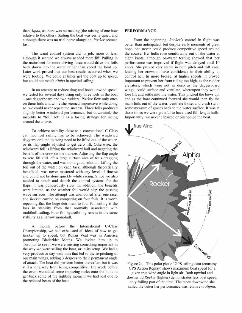
PERFORMANCE From the beginning, Rocker’s control in flight was
better than anticipated, but despite early moments of great hope, she never could produce competitive speed around the course. Her hulls rose comfortably out of the water at eight knots, although on-water testing showed that her performance was improved if flight was delayed until 10 knots. She proved very stable in both pitch and roll axes, leading her crews to have confidence in their ability to control her. In more breeze, at higher speeds, it proved important to prevent her from riding too high, as the rudder elevators, which were not as deep as the daggerboard wings, could surface and ventilate, whereupon they would lose lift and settle into the water. This pitched the bows up, and as the boat continued forward she would then fly the main foils out of the water, ventilate those, and crash (with some measure of grace) back to the water surface. It was at those times we were grateful to have used full-length hulls. Importantly, we never capsized or pitchpoled the boat.
Figure 24 - This polar plot of GPS sailing data (courtesy GPS Action Replay) shows maximum boat speed for a
given true wind angle in light air. Both upwind and downwind Rocker (lighter) demonstrates less boat speed,
only foiling part of the time. The more downwind she sailed the better her performance was relative to Alpha.

Working to windward on three foils in light air she was able to keep up with Patient Lady VI, and was faster downwind. On four foils she was never acceptable upwind, but she had her best performances downwind, frequently beating PLVI and occasionally approaching the speed of Alpha. During the regatta, Rocker’s helmsman, Dan Cunningham, reported that on a couple of downwind legs there were times when he thought Rocker was faster than Alpha or Cogito in light conditions, although he was by then too far behind to be certain.
PERFORMANCE AFTER SURGERY
After two days of fleet racing, the competitive story
of Rocker had been told. Paterson and Cunningham approached Fred Eaton about modifying the boat to try to salvage some of the regatta for themselves. After a couple of hours of discussion, which included Steve Clark of Cogito, we elected to cut the foils off the boat completely. Renamed Off Yer Rocker No More, she immediately proved to be competitive, easily beating PLVI with whom she had been pacing previously, and sailing near the speeds of Cogito and Rocker, despite using daggerboards and rudders designed more for foiling than displacement sailing.
ANALYSIS OF PROBLEMS
a) Righting Moment
To harness the power of the efficient hardsail in either
a standard or foiling C-Class cat, the crew must balance the overturning moment of the sail by hanging their weight on the trapeze. The further they are from the leeward hull, (normally the point about which the boat heels), the more power they can apply. The challenge with Rocker’s four-point configuration is that there is a foil still lifting under the windward hull and the effective point of heeling rotation has moved to the platform centerline some six feet inside the leeward hull. The loss of restoring moment is dramatic, and much of the time Rocker sailed with the mainsail operating at half power or less. Our experiments in three-point foiling solved the righting moment, but left our underwater wing area lacking. Perhaps a larger set of main wings and the ability to efficiently raise the windward foil are areas for future investigation.
b) Lateral Resistance to Windward
Sailing efficiently to windward requires an efficient
daggerboard of appropriate area. As a foiling cat increases its height above the water, the area of immersed daggerboard is reduced. Although there is an ideal height and area, it was easy to see the boat sag to leeward when the optimal ride height was exceeded and the daggerboards became less and less immersed.
c) Induced Drag The benefit of flying the hull of any boat is that the
wetted surface is dramatically reduced. In Rocker’s case the wetted surface of the four-point foiling configuration (including 2 wings, 2 elevators, 2 daggerboards and 2 rudders) is reduced to less than half of Alpha’s single leeward hull. Offsetting that reduction is the added induced drag of the elevator and wing lifting the combined 750 pounds of boat and crew. Perhaps a larger wing, with more wetted surface but less induced drag, would be a better trade-off. But we might also just be realizing the fact that a C-Class hull 25 feet long and less than a foot and a half wide is already a very efficient, low-drag torpedo, and that the gains to be made by foiling the boat are just not there. CONCLUSIONS
Rocker
After this fairly careful experiment in foiling, we are comfortable concluding that hydrofoils don’t perform in this configuration on a C-Class catamaran. There is no doubt that fine-tuning our parameters could increase Rocker’s speed, but it will take more than fine tuning to make the required leap in performance. We encourage other teams to learn from our experiments and go forward to find the solution that will push hydrofoiling catamarans to the next level of performance.
Alpha
In any race victory there are a host of small factors that combine to produce success. In our opinion, the three biggest factors that led to our win in the C Class Championships were:
- our lower overall weight - our higher aspect ratio, thinner foil section hardsail - more time on the water that gave us an edge in
boathandling and racecourse tactics There are obviously a host of other items, many
discussed in this paper, that proved important to the victory. I hope it is encouraging to note that in our analysis it is not all about technology, and that boat handling and tactics were still key components in the success story.
ACKNOWLEDGEMENTS
My thanks to Magnus Clarke and Fred Eaton for their
superb sailing, technical input and analysis during the tune-up sessions. Our continuing thanks to Steve Clark, Duncan MacLane and David Hubbard for “inviting us” into the class. We look forward to future events.
REFERENCES
Abbott, Ira H and Von Doenhoff, Albert E , “Theory of Wing Sections”, Dover Publications, New York, 1959
Grogono, James, “Icarus, The Boat That Flies”,
Adlard Coles Ltd., London, U.K. 1987 Killing, Steve, C-Class Catamaran Development ,
Seahorse Magazine, January, February, March, April 2008, Hampshire, UK
Recommended reading: Maclane, Duncan T., “The
Cogito Project: Design and Development of an International C-Class Catamaran and Her Successful Challenge to Regain the Little America’s Cup”, 13th Chesapeake Sailing Yacht Symposium , Annapolis MD
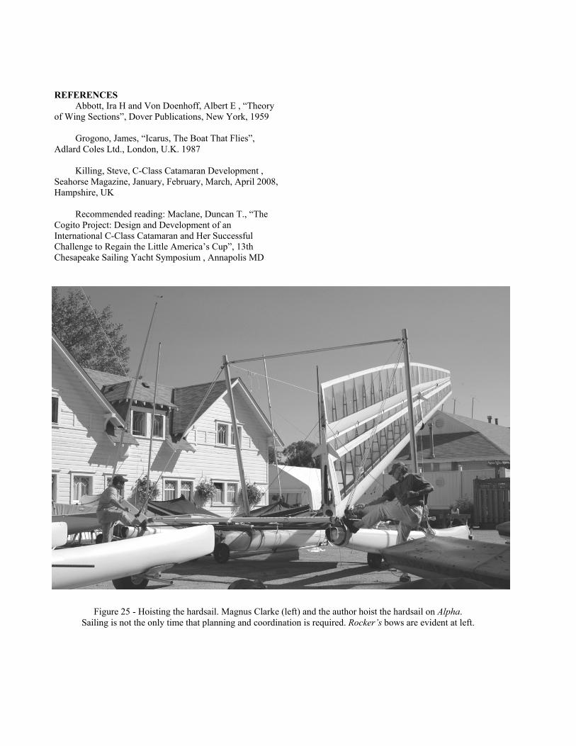
Figure 25 - Hoisting the hardsail. Magnus Clarke (left) and the author hoist the hardsail on Alpha. Sailing is not the only time that planning and coordination is required. Rocker’s bows are evident at left.