the 2012 audi a6 vehicle introduction -...
TRANSCRIPT

The 2012 Audi A6 Vehicle Introduction
Self-Study Program 990613
Audi of America, LLC
Service Training
Printed in U.S.A.
Printed 4/2011
Course Number 990613
©2011 Audi of America, LLC
All rights reserved. Information contained in this manual is
based on the latest information available at the time of printing
and is subject to the copyright and other intellectual property
rights of Audi of America, LLC., its affi liated companies and its
licensors. All rights are reserved to make changes at any time
without notice. No part of this document may be reproduced,
stored in a retrieval system, or transmitted in any form or by
any means, electronic, mechanical, photocopying, recording or
otherwise, nor may these materials be modifi ed or reposted to
other sites without the prior expressed written permission of
the publisher.
All requests for permission to copy and redistribute
information should be referred to Audi of America, LLC.
Always check Technical Bulletins and the latest electronic
service repair literature for information that may supersede any
information included in this booklet.
Table of Contents
Introduction . . . . . . . . . . . . . . . . . . . . . . . . . . . . . . . . . . . . . . .1
Body . . . . . . . . . . . . . . . . . . . . . . . . . . . . . . . . . . . . . . . . . . . . . .2 Exterior Dimensions . . . . . . . . . . . . . . . . . . . . . . . . . . . . . . . . . . . . . . . . . . . . . . . . . 2
Overview . . . . . . . . . . . . . . . . . . . . . . . . . . . . . . . . . . . . . . . . . . . . . . . . . . . . . . . . . . . 4
Occupant Protection . . . . . . . . . . . . . . . . . . . . . . . . . . . . . . . .6 Introduction . . . . . . . . . . . . . . . . . . . . . . . . . . . . . . . . . . . . . . . . . . . . . . . . . . . . . . . . 6
Engine . . . . . . . . . . . . . . . . . . . . . . . . . . . . . . . . . . . . . . . . . . .11 3.0L V6 TFSI Engine . . . . . . . . . . . . . . . . . . . . . . . . . . . . . . . . . . . . . . . . . . . . . . . . . 11
Innovative Thermal Management . . . . . . . . . . . . . . . . . . . . . . . . . . . . . . . . . . . . 13
ATF Heating / Cooling . . . . . . . . . . . . . . . . . . . . . . . . . . . . . . . . . . . . . . . . . . . . . . . 14
2.0L TFSI Engine . . . . . . . . . . . . . . . . . . . . . . . . . . . . . . . . . . . . . . . . . . . . . . . . . . . . 16
ATF Cooling . . . . . . . . . . . . . . . . . . . . . . . . . . . . . . . . . . . . . . . . . . . . . . . . . . . . . . . . 18
Power Transmission . . . . . . . . . . . . . . . . . . . . . . . . . . . . . . .20 Overview . . . . . . . . . . . . . . . . . . . . . . . . . . . . . . . . . . . . . . . . . . . . . . . . . . . . . . . . . . 20
Suspension System . . . . . . . . . . . . . . . . . . . . . . . . . . . . . . .22 Overview . . . . . . . . . . . . . . . . . . . . . . . . . . . . . . . . . . . . . . . . . . . . . . . . . . . . . . . . . . 22
Axles . . . . . . . . . . . . . . . . . . . . . . . . . . . . . . . . . . . . . . . . . . . . . . . . . . . . . . . . . . . . . . 23
Electromechanical Steering . . . . . . . . . . . . . . . . . . . . . . . . . . . . . . . . . . . . . . . . . . 24
Brake System . . . . . . . . . . . . . . . . . . . . . . . . . . . . . . . . . . . . . . . . . . . . . . . . . . . . . . 25
ESP . . . . . . . . . . . . . . . . . . . . . . . . . . . . . . . . . . . . . . . . . . . . . . . . . . . . . . . . . . . . . . . 26
Audi Drive Select . . . . . . . . . . . . . . . . . . . . . . . . . . . . . . . . . . . . . . . . . . . . . . . . . . . 27
Electrical System . . . . . . . . . . . . . . . . . . . . . . . . . . . . . . . . . .28 Power Supply Overview . . . . . . . . . . . . . . . . . . . . . . . . . . . . . . . . . . . . . . . . . . . . 28
Fuses and Relays . . . . . . . . . . . . . . . . . . . . . . . . . . . . . . . . . . . . . . . . . . . . . . . . . . . 29
Control Module Locations . . . . . . . . . . . . . . . . . . . . . . . . . . . . . . . . . . . . . . . . . . . 30
Topology . . . . . . . . . . . . . . . . . . . . . . . . . . . . . . . . . . . . . . . . . . . . . . . . . . . . . . . . . . 32
Exterior Lighting . . . . . . . . . . . . . . . . . . . . . . . . . . . . . . . . . . . . . . . . . . . . . . . . . . . . 34
Headlights . . . . . . . . . . . . . . . . . . . . . . . . . . . . . . . . . . . . . . . . . . . . . . . . . . . . . . . . . 36
Rear Lights . . . . . . . . . . . . . . . . . . . . . . . . . . . . . . . . . . . . . . . . . . . . . . . . . . . . . . . . 47
Rear Lights at Night . . . . . . . . . . . . . . . . . . . . . . . . . . . . . . . . . . . . . . . . . . . . . . . . 48
i
Table of Contents
ii
Climate Control . . . . . . . . . . . . . . . . . . . . . . . . . . . . . . . . . . .50 Overview . . . . . . . . . . . . . . . . . . . . . . . . . . . . . . . . . . . . . . . . . . . . . . . . . . . . . . . . . . 50
Infotainment . . . . . . . . . . . . . . . . . . . . . . . . . . . . . . . . . . . . . .51 Introduction . . . . . . . . . . . . . . . . . . . . . . . . . . . . . . . . . . . . . . . . . . . . . . . . . . . . . . . 51
Topology . . . . . . . . . . . . . . . . . . . . . . . . . . . . . . . . . . . . . . . . . . . . . . . . . . . . . . . . . . 51
Radio Media Center (RMC) . . . . . . . . . . . . . . . . . . . . . . . . . . . . . . . . . . . . . . . . . . . 52
MMI Radio Plus (RMC) . . . . . . . . . . . . . . . . . . . . . . . . . . . . . . . . . . . . . . . . . . . . . . . 53
MMI Navigation Plus . . . . . . . . . . . . . . . . . . . . . . . . . . . . . . . . . . . . . . . . . . . . . . . . 54
Google Earth Mapping . . . . . . . . . . . . . . . . . . . . . . . . . . . . . . . . . . . . . . . . . . . . . . 56
WLAN Hotspot . . . . . . . . . . . . . . . . . . . . . . . . . . . . . . . . . . . . . . . . . . . . . . . . . . . . . 57
Operating Unit . . . . . . . . . . . . . . . . . . . . . . . . . . . . . . . . . . . . . . . . . . . . . . . . . . . . . 59
MMI Display . . . . . . . . . . . . . . . . . . . . . . . . . . . . . . . . . . . . . . . . . . . . . . . . . . . . . . . 60
MMI Display Swivel Mechanism . . . . . . . . . . . . . . . . . . . . . . . . . . . . . . . . . . . . . 61
Sound Systems . . . . . . . . . . . . . . . . . . . . . . . . . . . . . . . . . . . . . . . . . . . . . . . . . . . . 62
Antenna Overview . . . . . . . . . . . . . . . . . . . . . . . . . . . . . . . . . . . . . . . . . . . . . . . . . 64
Head-Up Display . . . . . . . . . . . . . . . . . . . . . . . . . . . . . . . . . .65 Introduction . . . . . . . . . . . . . . . . . . . . . . . . . . . . . . . . . . . . . . . . . . . . . . . . . . . . . . . 65
Display Information . . . . . . . . . . . . . . . . . . . . . . . . . . . . . . . . . . . . . . . . . . . . . . . . . 66
Windshield Projection Display Control Module J898 . . . . . . . . . . . . . . . . . . . . 68
Self-Study Programs for the 2012 Audi A7 . . . . . . . . . . .72
Knowledge Assessment . . . . . . . . . . . . . . . . . . . . . . . . . . .73
Reference Note
!
The Self-Study Program provides introductory information regarding the design
and function of new models, automotive components, or technologies.
The Self-Study Program is not a Repair Manual!All values given are intended as a guideline only.
For maintenance and repair work, always refer to current technical literature.

Introduction
1
The lineage of the Audi A6 sedan begins in
the late 1960s with the launch of the Audi 100.
The impact of the Audi 100 was revolutionary,
embodying what was to become a new
innovative spirit for the Audi brand.
With its classic, uncluttered design, the Audi 100
formed the cornerstone for many legendary Audi
C-platform vehicles that would emerge in the
1970s, ‘80s, and ‘90s, each leaving a lasting mark
and forecasting the future.
In the process, the Audi 100 became the Audi
A6. Through it all, timeless and innovative
Audi design cues and technology redefi ned
automotive elegance and sportiness for each
new decade.
The 2012 Audi A6 continues this tradition.
Its Audi internal designation is C7, being the
seventh generation of the company’s C-platform.
Like its predecessors, the C7 design inspires and
creates enthusiasm.
The new Audi A6 is a remarkable sedan that
blends comfort and sport characteristics
seamlessly. It is both a practical car and a car
that excites every time you turn the wheel. Many
of the A6’s technology and comfort features
have only been available previously in luxury
class vehicles.
What the Audi 100 began, the new Audi A6 takes
to new levels.
486_064

Body
2
Exterior Dimensions
486_016486_015
57.2
in (1
445
mm
)
73.7 in (1874 mm)
64.05 in (1627 mm)
82.1 in (2086 mm)
63.7 in (1618 mm)
37.3 in (949 mm)
114.6 in (2912 mm)
193.5 in (4915 mm)
42.9 in(1091 mm)
35.9 in(916 mm)
26.5
in(6
74 m
m)
478_031
37.8
in(9
62 m
m)
41.1
in(1
046
mm
)

3
Length
Width
Height
Front track width
Rear track width
Wheelbase
Curb weight
Maximum
gross weight
193.5 in (4915 mm)
73.7 in (1874 mm)
57.2 in (1455 mm)
64.05 in (1627 mm)
63.7 in (1618 mm)
114.6 in (2912 mm)
3472.2 lb (1575 kg)
4750.9 lb (2155 kg)
Front internal width
Rear internal width
Front headroom
Rear headroom
Loading width
Load sill height
Trunk capacity
Fuel tank capacity
Drag coeffi cient
57.4 in (1460 mm)
56.2 in (1429 mm)
41.1 in (1046 mm)
37.8 in (962 mm)
37.3 in (949 mm)
26.5 in (674 mm)
18.7 cu ft / 35.1 cu ft
(530 l / 995 l)
19.8 gal (75.0 l)
0.26
486_018
58.7
in (1
491
mm
)58
.7 in
(149
1 m
m)
57.4
in (1
460
mm
)57
.4 in
(146
0 m
m)
60.1
in (1
527
mm
)60
.1 in
(152
7 m
m)
56.2
in (1
429
mm
)56
.2 in
(142
9 m
m)
41.3 in41.3 in(1050 mm)(1050 mm)
46.2 in (1176 mm)46.2 in (1176 mm)
4
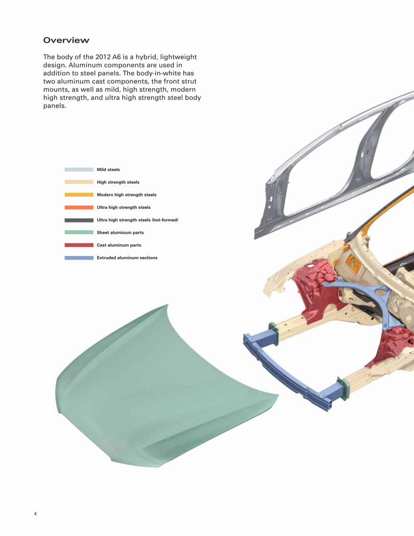
Overview
The body of the 2012 A6 is a hybrid, lightweight
design. Aluminum components are used in
addition to steel panels. The body-in-white has
two aluminum cast components, the front strut
mounts, as well as mild, high strength, modern
high strength, and ultra high strength steel body
panels.
Mild steels
High strength steels
Modern high strength steels
Ultra high strength steels
Ultra high strength steels (hot-formed)
Sheet aluminum parts
Cast aluminum parts
Extruded aluminum sections

5
486_019

Occupant Protection
6
Introduction
The occupant protection system in the 2012
A6 is comparable to that of the 2012 Audi A7,
with individual components adapted to the
A6. A safety belt warning feature for the rear
passengers is new.
ReferenceFor more information about the occupant safety system of the 2012 Audi A6, refer to Self-Study Program
920603, The 2012 Audi A7 Occupant Protection, Infotainment, Climate Control, and Head-Up Display.

7
486_011

8
K19 Seat Belt Indicator Light
K75 Airbag Indicator Lamp
K145 Front Passenger Airbag –Disabled– Indicator Lamp
N95 Driver Airbag Igniter
N131 Front Passenger Airbag Igniter 1
N132 Front Passenger Airbag Igniter 2
N153 Driver Seat Belt Tensioner Igniter 1
N154 Front Passenger Seat Belt Tensioner Igniter 1
N196 Left Rear Seat Belt Tensioner Igniter
N197 Right Rear Seat Belt Tensioner Igniter
N199 Driver Thorax Airbag Igniter
N200 Front Passenger Thorax Airbag Igniter
N201 Left Rear Thorax Airbag Igniter
N202 Right Rear Thorax Airbag Igniter
N251 Driver Head Curtain Airbag Igniter
N252 Passenger Head Curtain Airbag Igniter
N253 Battery Interrupt Igniter
N295 Driver Knee Airbag Igniter
N296 Front Passenger Knee Airbag Igniter
N490 Driver Airbag Release Valve Igniter
T16 Data Link Connector
E24 Driver’s Seat Belt Switch
E25 Front Passenger Seat Belt Switch
E258 Driver Side Rear Seat Belt Switch
E259 Front Passenger Side Rear Seat Belt Switch
E609 Center Rear Seat Belt Switch
G128 Front Passenger Seat Occupant Sensor
G179 Driver Side Airbag Crash Sensor
G180 Front Passenger Side Airbag Crash Sensor
G256 Driver Side Rear Side Airbag Crash Sensor
G257 Front Passenger Side Rear Side Airbag Crash Sensor
G283 Driver Front Airbag Crash Sensor
G284 Front Passenger Front Airbag Crash Sensor
G551 Driver Belt Force Limiter
G552 Front Passenger Belt Force Limiter
G553 Driver Seat Position Sensor
G554 Front Passenger Seat Position Sensor
J234 Airbag Control Module
J285 Instrument Cluster Control Module
J533 Data Bus On Board Diagnostic Interface
J623 Engine Control Module
J706 Passenger Occupant Detection System Control Module
J854 Left Front Seat Belt Tensioner Control Module
J855 Right Front Seat Belt Tensioner Control Module
Legend:
Components
The following components are used in the 2012
A6 occupant protection system for the North
American market:
– Airbag control module
– Adaptive driver and front passenger airbags
– Front side airbags
– Audi Sideguard (side curtain airbags)
– Driver and front passenger knee airbags
– Up-front airbag crash sensors
– Door-integrated pressure type sensors for side
impact detection
– Acceleration-type sensors for side impact
detection on the C-pillars
– Front inertia-reel safety belts with pyrotechnic
and electrically reversible belt tensioners and
active belt force limiters
– Battery interrupt igniter
– Safety reminder for driver and front passenger
– Safety belt switch, driver and front passenger
– Seat occupancy sensor in front passenger seat
(PODS)
– Driver and front passenger seat position
recognition
– Rear passenger safety belt usage warning

9
A6_Airbag_USAa

10
Driver and Front PassengerSeat Belt Switches E24 and E25
E24 and E25 are integrated into the front
safety belt buckles. These reed switches are
components of the safety belt reminder system.
If the safety belt is not buckled, the reed switch
is closed. In this position, a magnet built into the
tip of a plastic pin acts on the reed switch.
If the safety belt is buckled, the reed switch is
open. The inserted belt tongue lifts the plastic
pin. The magnet no longer acts on the reed
switch and it opens. Airbag Control Module J234
reads the resistance and determines if the safety
belt is buckled or not.
484_011
484_010
Plastic pin
Magnet
Reed switchRear Safety Belt Reminder
After the ignition is switched ON, a status display
for the rear safety belts (fastened/not fastened)
appears for approximately 31 seconds in the
Driver Information System of the instrument
cluster.
At each change in status, a new display appears
for approximately 31 seconds. If a rear-seat
passenger unfastens the safety belt while the
vehicle is moving at a speed above 15.5 mph (25
km/h), an acoustic warning sounds once and the
corresponding indicator in the display begins
fl ashing for approximately 31 seconds.
Airbag Control Module J234 receives the
information whether the safety belts are
fastened through the rear safety belt switches
(E258, E259, E609.)
486_012Safety belt fastened
Safety belt not fastened
486_013
Blinks 31 seconds
> 15.5 mph(25 km/h)
OFF
Safety belt
ON“terminal 15”
Visual warning
Acoustic warning
< 15.5 mph(25 km/h)
Active
Rear safety belt not fastened warning
OFF
Lights 31 seconds
Lights 31 seconds
Active
OFF
Vehicle speed
Not
FastenedFastened

Engine
11
3.0L V6 TFSI Engine
Technical Features
486_003
Adapted belt drive(without power steering pump)
ReferenceFor further information about the design and operation of the 3.0L V6 TFSI engine, refer to Self-Study
Program 925803, The Audi 3.0L V6 TFSI Engine with Roots Blower.
Modifi cations to the 3.0L V6 TFSI Engine for the 2012 A6
Cylinder block
Cylinders
Main bearing
inserts
Chain drive
Camshafts
Camshaft
adjusters
Valve gear
Oil pump
– New Innovative Thermal Management System (ITM)
– Honed to a textured fi nish to reduce oil consumption and wear
– Increased piston installation clearance
– Reduced pre-stress on the third piston ring land
– Bearing surfaces coated with an additional wear-resistant
layer designed to withstand composite friction
– Chain tensioners reconfi gured and adapted for reduced oil fl ow
– Weight of intake valve camshafts reduced
– Cam contour revised
– Weight of exhaust valve camshafts reduced
– All camshafts are now composite construction
– Enhancements reduce leakage, resulting in reduced oil circuit pressure
– Reduced spring forces
– Smaller, consumes less power, and generates less friction
Spark plugs – Heat ratings adapted for optimized combustion

12
Specifi cations
Engine type
Displacement
Maximum power
Maximum torque
Valves per cylinder
Bore
Stroke
Compression ratio
Powertrain
Six cylinder V engine with 90° included angle
182.7 cu in (2995 cc)
310 hp (220 kW) @ 5500–6500 rpm
325 lb ft (440 Nm) @ 2900–4500 rpm
4
3.32 in (84.5 mm)
3.50 in (89.0 mm)
10.5 : 1
quattro
Engine Code CGWB
Engine management
Fuel grade
Exhaust emission standard
Simos 8
91 AKI
ULEV 2
Power in hp (kW)
Torque in lb ft (Nm)
478_053
268.2 hp (200 kW)
201.1 hp (150 kW)
234.6 hp (175 kW)
167.6 hp (125 kW)
134.1 hp (100 kW)
301.7 hp (225 kW)
hp (kW)
335.2 hp (250 kW)
100.5 hp (75 kW)
0
33.5 hp (25 kW)
295.0 lb ft (400 Nm)
221.2 lb ft (300 Nm)
258.1 lb (350 Nm)
184.3 lb ft (250 Nm)
147.5 lb ft (200 Nm)
331.9 lb ft (450 Nm)
lb ft (Nm)
368.7 lb ft (500 Nm)
110.6 lb ft (150 Nm)
36.8 lb ft (50 Nm)
2000 4000 5000 70001000 3000 6000

13
Innovative Thermal Management
Innovative Thermal Management (ITM) for the
3.0L V6 TFSI engine is similar to the system
designed for the 2011 Audi A8 4.2L V8 TFSI. It is
an electronically controlled system designed to
optimally distribute engine heat fl ow. The system
is controlled by the Heat Manager, a recently
developed software module fully integrated into
the engine control module (ECM).
The engine coolant is distributed on demand
between the engine, transmission, and
passenger compartment by a system of valves.
To ensure maximum comfort, the demands of
the heating and climate control systems are
evaluated at all times.
The climate control and transmission
control modules communicate their heating
requirements to the ECM via CAN bus. These
heating requirements, together with the engine
heating request from the ECM, are then analyzed
and prioritized. ITM components are activated
accordingly.
During phase one of operation, the engine
coolant does not circulate. This results in the
stationary coolant temperature increasing faster
than if it was circulated, thus reducing frictional
losses in the engine.
After the non-circulation phase, engine
coolant is used to rapidly heat the ATF via a
heat exchanger. The coolant is directed by
an electrical control valve actuated by the
Transmission Control Module.
A mixing phase is cycled by the ECM to ensure
that hot engine coolant is not circulated
immediately, which would impair the frictional
properties of the engine.
Passenger Compartment Heating
The stationary coolant phase normally takes
approximately 120 seconds. However, there
are circumstances where stationary coolant is
unwanted, for example, when the Defrost button
is pressed. Warm coolant fl ows immediately to
the heater in order to prevent the windshield
from fogging up.
If the heater does not need any energy to
heat the vehicle interior (at warm ambient
temperatures), the climate control module does
not send a heating request.
Transmission Heating/Cooling
The ATF is heated and cooled as needed, and
is only cooled to the temperature level of the
engine coolant.
ITM System Technical Summary
– Active coolant pump
Two sensors:
– Engine Temperature Control
Temperature Sensor G694
– Coolant Temperature Sensor G62
– ATF heating/cooling
– Heating cut off
– Thermostat opens at 188.6°F (87°C)
ReferenceFor more information about the Innovative Thermal Management system of the 3.0L V6 TFSI engine,
refer to Self-Study Program 990203, The 2012 Audi A7 Introduction.

14
ATF Heating / Cooling
Overview
The software for the Innovative Thermal
Management (ITM) system is located in the
Engine Control Module. It receives information
about ATF temperature from Transmission
Control Module J217.
486_068
2
G694G694
F265
V188
J293
N4897
5
G62
J671
9
1011
8
N509
6
4
2
5
ATF
Warmed coolant (charge air coolant)
Warmed coolant
Cooled coolant
Cooled coolant (charge air coolant)
1
V502
3
ITM controls heating and cooling of the ATF. The
ECM gives the TCM the command to open or
close the Transmission Fluid Cooling Valve N509.
1 Heat exchange (passenger compartment)
2 Bleeders
3 Quick connector (black)
4 ATF heat exchanger
5 Charge air intercooler
6 Engine coolant expansion bottle
7 Active engine coolant pump
8 Engine oil cooler
9 Radiator
10 Low temperature cooler for coolant
11 Low temperature auxiliary cooler for engine coolant
G62 Engine Coolant Temperature Sensor
G694 Engine Temperature Control Temperature Sensor
J293 Coolant Fan Control Module1
J671 Coolant Fan Control Module 21
N489 Cylinder Head Coolant Valve1,4
N509 Transmission Fluid Coolant Valve2
V50 Coolant Recirculation Pump3
V188 Charge Air Cooling Pump1
Legend:
1 Controlled to ECM J6232 Controlled by TCM J2173 Controlled by Climatronic Control Module J2554 Switches the engine coolant pump
15
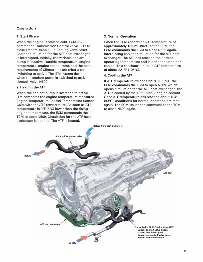
Operation
1. Start Phase
When the engine is started cold, ECM J623
commands Transmission Control Valve J217 to
close Transmission Fluid Cooling Valve N509.
Coolant circulation for the ATF heat exchanger
is interrupted. Initially, the variable coolant
pump is inactive. Outside temperature, engine
temperature, engine speed (rpm), and the heat
requirements of Climatronic are criteria for
switching to active. The ITM system decides
when the coolant pump is switched to active
through valve N509.
2. Heating the ATF
When the coolant pump is switched to active,
ITM compares the engine temperature measured
Engine Temperature Control Temperature Sensor
G694 with the ATF temperature. As soon as ATF
temperature is 9°F (5°C) lower than the rising
engine temperature, the ECM commands the
TCM to open N509. Circulation for the ATF heat
exchanger is opened. The ATF is heated.
3. Normal Operation
When the TCM reports an ATF temperature of
approximately 183.2°F (84°C) to the ECM, the
ECM commands the TCM to close N509 again,
interrupting coolant circulation for the ATF heat
exchanger. The ATF has reached the desired
operating temperature and is neither heated nor
cooled. This continues up to an ATF temperature
of about 221°F (105°C).
4. Cooling the ATF
If ATF temperature exceeds 221°F (105°C), the
ECM commands the TCM to open N509, which
opens circulation for the ATF heat exchanger. The
ATF is cooled by the 185°F (85°C) engine coolant.
Once ATF temperature has reached about 194°F
(90°C), conditions for normal operation are met
again. The ECM issues the command to the TCM
to close N509 again.
486_069
ATF heat exchanger
Return
Supply
Return from heat exchanger
Transmission Fluid Cooling Valve N509 – Current applied: valve closed, coolant fl ow interrupted – Current not applied: valve open, coolant fl ow unrestricted
Black quick-connect valve
16
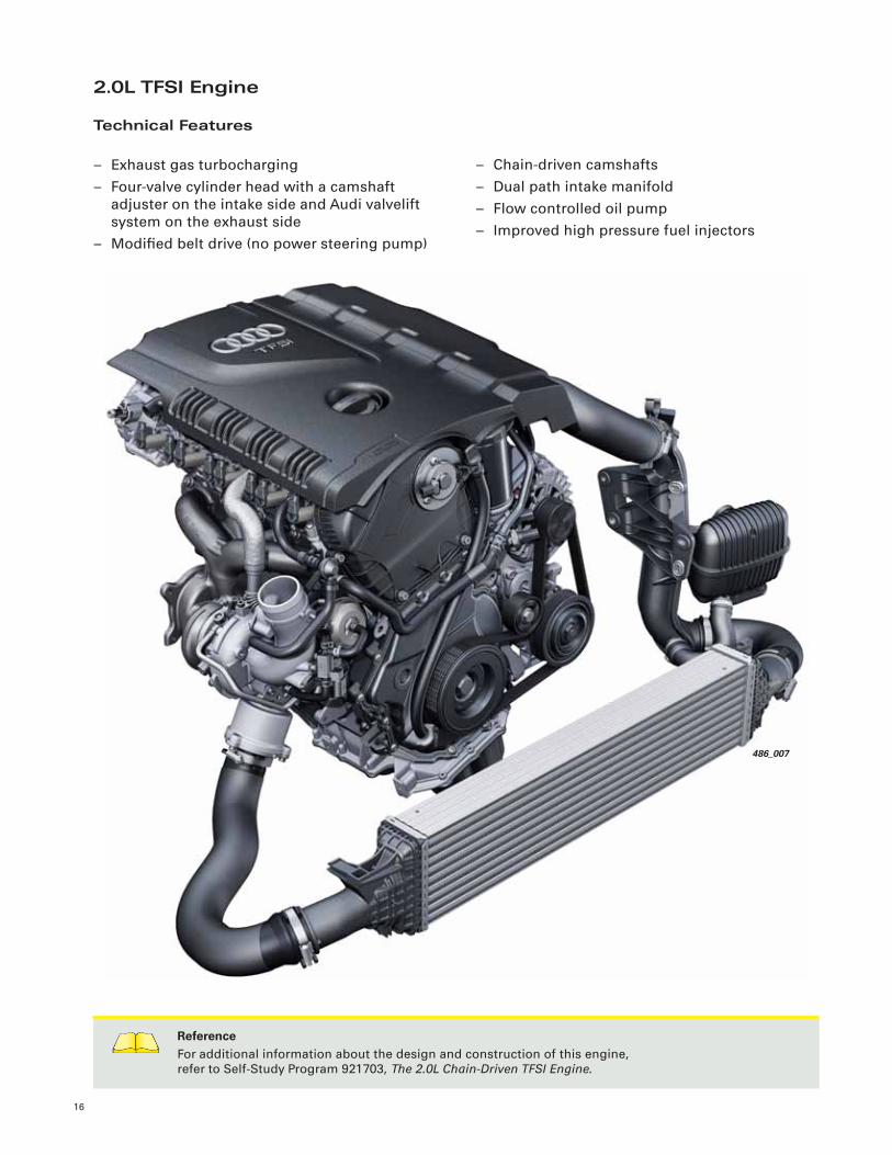
– Chain-driven camshafts
– Dual path intake manifold
– Flow controlled oil pump
– Improved high pressure fuel injectors
2.0L TFSI Engine
Technical Features
– Exhaust gas turbocharging
– Four-valve cylinder head with a camshaft
adjuster on the intake side and Audi valvelift
system on the exhaust side
– Modifi ed belt drive (no power steering pump)
486_007
ReferenceFor additional information about the design and construction of this engine,
refer to Self-Study Program 921703, The 2.0L Chain-Driven TFSI Engine.

17
Specifi cations
Engine type
Displacement
Maximum power
Maximum torque
Valves per cylinder
Bore
Stroke
Compression ratio
Powertrain
Four cylinder inline engine
121.0 cu in (1984 cc)
177 hp (123 kW) @ 4000–6000 rpm
236 lb ft (320 Nm) @ 1500–3900 rpm
4
3.24 in (82.5 mm)
3.65 in (92.8 mm)
9.6 : 1
Multitronic
Engine Code CDNB
Engine management
Fuel grade
Bosch MED 17.1
91 AKI
Power in hp (kW)
Torque in lb ft (Nm)
486_008
160.9 hp (120 kW)
120.6 hp (90 kW)
140.8 hp (105 kW)
100.5 hp (75 kW)
80.4 hp (60 kW)
181.0 hp (135 kW)
40.2 hp (30 kW)
201.1 hp (150 kW)
hp (kW)
0
20.1 hp (15 kW)
236.0 lb ft (320 Nm)
177.0 lb ft (240 Nm)
206.5 lb (280 Nm)
147.5 lb ft (200 Nm)
118.0 lb ft (160 Nm)
265.5 lb ft (360 Nm)
59.0 lb ft (80 Nm)
295.0 lb ft (400 Nm)
lb ft (Nm)
29.5 lb ft (40 Nm)
2000 4000 5000 70001000 3000 6000 8000
18
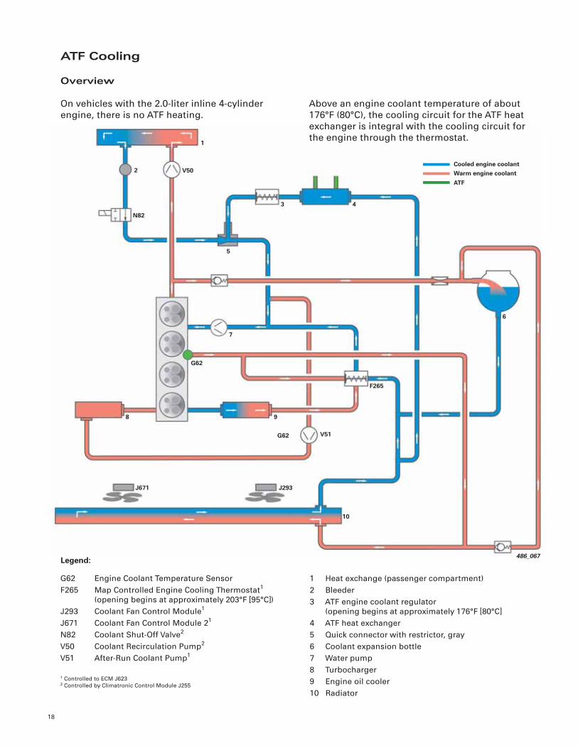
ATF Cooling
Overview
On vehicles with the 2.0-liter inline 4-cylinder
engine, there is no ATF heating.
486_067
2
F265
V51
J293
G62
9
5
G62
J671
10
8
N82
6
4
7
ATF
Warm engine coolantCooled engine coolant
1
V50
3
Above an engine coolant temperature of about
176°F (80°C), the cooling circuit for the ATF heat
exchanger is integral with the cooling circuit for
the engine through the thermostat.
1 Heat exchange (passenger compartment)
2 Bleeder
3 ATF engine coolant regulator
(opening begins at approximately 176°F [80°C]
4 ATF heat exchanger
5 Quick connector with restrictor, gray
6 Coolant expansion bottle
7 Water pump
8 Turbocharger
9 Engine oil cooler
10 Radiator
G62 Engine Coolant Temperature Sensor
F265 Map Controlled Engine Cooling Thermostat1
(opening begins at approximately 203°F [95°C])
J293 Coolant Fan Control Module1
J671 Coolant Fan Control Module 21
N82 Coolant Shut-Off Valve2
V50 Coolant Recirculation Pump2
V51 After-Run Coolant Pump1
Legend:
1 Controlled to ECM J6232 Controlled by Climatronic Control Module J255

19
Direction of Flow
When installing the ATF coolant regulator, strict
attention must be paid to the direction of fl ow,
which is identifi ed by an arrow on the regulator
housing.
In the event of incorrect installation, regulation
is undesirably affected and ATF cooling is
obstructed. If the groove in the valve seat is
contaminated, the very small permanent fl ow of
coolant is interrupted, and the thermal element
is not properly heated. The valve seat remains
closed and the ATF is not cooled.
If there is excessive ATF temperature, then
coolant and fl uid circulation to the ATF heat
exchanger, as well as the coolant regulator, must
be checked.
486_070
Closed
Supply
Return from heat exchanger
Thermal element with lift rod
Quick connector with restrictor (gray)
Coolant regulator
Opened
Return
Quick Connector with Restrictor
The quick connect with restrictor (gray) is used in
vehicles with the 2.0L, 4-cylinder TFSI engine. A
quick connect without restrictor (black) is used
on vehicles with the 3.0L V6 TFSI engine.
If the quick connect without restrictor (black) is
installed in vehicles with the 2.0L TFSI engine
instead of the specifi ed quick connect with
restrictor (gray), the cooling performance of the
ATF heat exchanger will be reduced. This can
cause elevated ATF temperatures.
ATF Thermostat
An ATF coolant regulator is installed in the
coolant return of the ATF heat exchanger. A
groove in the valve seat allows a very small
permanent fl ow of engine coolant. If coolant
temperature rises, the wax in the thermal
element is heated and expands. As a result, it
opens the valve seat through the lift rod and
coolant circulation is enabled when the coolant
temperature reaches 176°F (80°C).

Power Transmission
20
ReferenceFor more details about the mechanical operation of the 0BK transmission, refer to Self-Study Program
950103, The 2011 Audi A8 Power Transmission.
478_018
0BK transmission
Axle fl ange with new sealing and assembly design(as in the B8 series)
0BF sport differential (not offered with 0BK
transmission)
Overview
The 2012 A6 is introduced with the 8-speed 0BK
automatic transmission. This transmission was
designed specifi cally for the North American
market.
It is the same transmission used in the 2011
A8 but does not feature the “shift-by-wire”
control system. Instead, it uses a cable operated
mechanical selector.

21
478_010
Splined prop shaft: Weight reduction by elimination of
the bolted fl ange connection
Forward mountedfi nal drive
(as with the B8 series)
478_027
Multitronic 0AW
– Step-less transmission for future front- wheel drive models with engines rated up to 295 lb ft (400 Nm)
478_011
0B5 S tronic 7-speed transmission
– 7-speed dual clutch transmission for future use on quattro models

Suspension System
22
478_073
Overview
One of the key development goals for the A6
was to provide outstanding agility, driveability
and driving enjoyment while also offering a high
standard of safety and comfort. This was made
possible by adopting the proven design of Audi’s
fi ve-link front suspension combined with a self-
tracking trapezoidal-link rear axle.
A steel-sprung suspension with conventional
shock absorbers is standard.
The A6 uses the same powertrain design that
was fi rst used on the Audi A5, with the axle drive
positioned ahead of the differential to provide a
large wheelbase and small front overhang.
Mounting the steering gear on the subframe in
front of the front axle provides the necessary,
exact steering response and a precise steering
feel in every driving situation.
Electro-mechanical steering provides improved
fuel economy in addition to allowing more
functional options related to handling and
control.
ReferenceFor further information about the suspension system of the 2012 A6, refer to Self-Study Program 990303,
The 2012 Audi A7 Running Gear and Suspension.
Production Control Number (PR)
1BA
1BE
1BV
1BK
Steel suspension
Steel suspension
Steel suspension
Air suspension
DescriptionTechnicalImplementation
Offer
Standard running gear /suspension
Sports running gear /suspension
Sports running gear /suspension
S line (offered from quattro GmbH)
Adaptive air suspension
(not available at launch)
Series standard
Option
Option
Option

23
Axles
Front Axle
The A6 uses the fi ve-link front suspension of the
2011 A8 as a starting point. The bearing pedestal
that supports the upper wishbone has been
integrated into the body shell.
In addition to saving weight and increasing
rigidity, this also reduces the fi tting tolerances
of the upper wishbones. Anti-roll bars and shock
absorbers have been reconfi gured to meet the
design objectives of the A6.
Rear Axle
The rear suspension design is based on the
trapezoidal link rear axle used on the Audi Q5.
Springs and shock absorbers are separated from
one another, providing a large pass-through
loading width and a fl at load fl oor.
478_074
478_075

24
Electromechanical Steering
Overview
The new generation of electromechanical power
steering used on the 2012 A7 is also used on the
2012 A6. The power assist is accomplished via an
electric motor arranged concentrically in relation
to the steering rack. This design was selected
because it enables high performance capability
with relatively small space requirements.
The rack, electric motor, ball screw assembly,
control module and necessary sensors are
integrated into a compact unit.
This complete steering system is approximately
35.2 lb (16 kg) lighter than earlier versions. The
weight reduction means better fuel consumption
and increased functionality with other vehicle
safety and handling systems.
480_033
Electromechanical Power Steering Motor
V187 with rotor position
Steering pinion
Ball screw assembly
Power Steering Control Module J500
Rack
Steering Torque Sensor G269

25
Brake System
Overview
The A6 brake system is similar in design and
operation to that of the 2011 A8 and 2012 A7. An
electromechanical parking brake is used at the
rear.
478_072
A high performance ESP by Bosch, which has
an extended range of functions, provides
a high standard of safety. As on the 2011
A8, Sensor Electronics Control Module J849
supplies information about vehicle dynamics for
calculation of desired control operations. The
system used in the A6 is identical to that of the
A8.
486_082
17” 2FNR 42 AL aluminum fl oating frame type caliper
New ESP system by Bosch, with extended
range of functions
Tandem master brake cylinder with 8/9 inch tandem brake booster
Rear wheel brakes combined with
electromechanical parking brake (EPB)
Sensor Electronics Control Module J849

26
Tire Pressure Monitoring
Audi’s familiar second-generation tire pressure
monitoring system is also used on the A6. The
system is standard on this model worldwide and
is identical to those already in use on other Audi
models.
486_085
Control module
Hydraulic module
Pump piston
Electric motor
Valves
Solenoid valves
Pressure sensor
ESP
The 2012 A6 uses the 9th generation ESP
Premium. The range of functions was expanded
for the future use of dynamic steering.
ABS Control Module J104 determines necessary
steering intervention to assist vehicle stability.
To do this, the values measured by the wheel
speed sensors, the steering angle sensor, Sensor
Electronics Control Module J794, and the rotor
position sensor of the dynamic steering actuator
are processed.
When needed, J104 then “instructs” the control
unit for Active Steering Control Module J792 to
perform a steering correction, irrespective of the
steering action by the driver. This feature will not
be available during the 2012 model year.
Diagnosis procedures are identical to those for
the Audi A6. As already implemented in the Audi
A6, the innovative functions of wheel-selective
torque vectoring (for quattro drive) and the
electronic locking differential (for front-wheel
drive) are also used in the 2012 A6.
The control module can be removed from
the hydraulic unit for service and replaced
separately. The installation operations must be
performed in an ESD-protected workplace using
special service tool VAS 6613.
486_086

27
Audi Drive Select
Audi Drive Select will also be offered on the 2012
A6.
There are three modes: comfort, auto, and
dynamic. The driver can select these via the MMI
control panel and, for example, switch from a
sport to a comfort driving mode. The drive can
use the individual mode to confi gure the vehicle.
For instance, a sport engine setup can be
combined with light steering action. The model
and option level dictates which systems can be
confi gured by Audi drive select. In all cases, the
engine, transmission, and steering systems are
controlled.
comfort auto dynamic
Engine/transmission
Air suspension*
Steering
Sport differential*
Reversible belt
pretensioners
balanced
balanced
balanced
responsive
standard
sport
sport
sport
sport
adapted activation
timing
balanced
comfort
comfort
balanced
standard
Mode Characteristics
*Not on US models at the introduction of the A6.
A6_AudiDriveSelect
ReferenceFor more information about the Audi drive select system and its mode characteristics,
refer to Self-Study Program 990203, The 2012 Audi A7 Vehicle Introduction.

Electrical System
28
Power Supply Overview
Refer to current technical literature for exact fuse
assignments and cable routing.
Starter
481_018
Power Steering Control Module J500
Alternator
Jump Start Terminal
Voltage distributor in plenum chamber
Fuse and relay carrier SD
Fuse carrier SC
Main fuse at battery positive terminal
Battery Interrupt Igniter N253
Fuse carrier SF
Grounding point in spare tire well
Battery Monitoring Control Module J367
Battery
Coolant Fan Control Module J293 and Coolant Fan Control Module 2 J671
Fuse carrier SA
Fuse carrier SB

29
Fuses and Relays
Voltage distributor in plenum chamber
The coolant fan control
modules are supplied
power via fuses located
at this point. The main
battery cable junction
point is here.
Fuse and relay carrier on the right side of the instrument panel
The fuses are labeled
SC in the current fl ow
diagram. They can
be accessed by the
customer after removing
the instrument panel
end cover.
Fuse and relay carrier in the E-box in the plenum chamber, driver side
(under the windshield
washer system reservoir)
The E-box lid also serves
as a support for the
engine control module.
The fuses in the E-box are
labelled SA in the current
fl ow diagram.
Fuse and relay carrier on the instrument panel, left
The fuses are labeled
SB in the current
fl ow diagram. They
can be accessed
by the customer
after removing the
instrument panel end
cover.
Main fuse carrier at battery positive terminal
The battery interrupt
igniter is also mounted
on this fuse carrier.
Coupling station and CAN node connector at the bottom left A-pillar
Fuse and relay carrier in the Vehicle Electrical System Control Module area
(below the instrument
panel in the driver
footwell)
The fuses are labeled
SD in the current fl ow
diagram.
Fuse and relay carrier and CAN node connector in luggage compartment, right
The fuses are labeled SF in
the current fl ow diagram.
The fuses can be accessed
by the customer after
removing the storage
compartment on the right
side.
A6_Electrical_System

30
J428J428
R212R212
J850J850
J500J500 J217J217
J623J623
J104J104
R161R161
J852J852
J844J844
J898J898
J519J519
J745J745
J851J851
J794J794
J255J255
J285J285
G85G85
J527J527
J853J853
J234J234 J849J849
J387J387
J521J521
J136J136
J386J386
Control Module Locations
Some of the control modules shown in this
overview are optional and/or are country-specifi c
equipment. Boxes without numbers in the
illustration indicate locations for components
not used in the North American market. The
color of a box indicates which data bus it
communicates on.
Refer to current technical literature for exact
installation locations of control modules, as well
as for installation and removal instructions.
Control Modules on the Convenience CAN busJ136 Memory Seat/Steering Column Adjustment CM
J386 Driver Door Control Module
J387 Front Passenger Door Control Module
J393 Comfort System Central Control Module
J519 Vehicle Electrical System Control Module
J521 Front Passenger Memory Seat Control Module
J605 Rear Lid Control Module
J872 Front Passenger Multicontour Seat CM
J873 Driver Multicontour Seat Control Module
Key:
Control Modules on the Display and Control CAN bus
E265 Rear A/C Display Control Head
J255 Climatronic Control Module
J285 Instrument Cluster Control Module
J527 Steering Column Electronics Control Module
J772 Rear View Camera System Control Module
J791 Parallel Parking Assistance Control Module
J898 Windshield Projection Head-Up Display CM
Control Modules on the Powertrain CAN busG85 Steering Angle Sensor
J234 Airbag Control Module
J540 Electromechanical Parking Brake Control Module
J623 Engine Control Module
J217 Transmission Control Module

31
481_009
J855J855
J872J872
E265E265
J873J873
J533J533
J854J854
J492J492
J769J769J772J772
J791J791
J197J197
J540J540
J393J393J605J605
J770J770
Radio RRadio RJ525J525
Control Modules on the FlexRay busJ104 ABS Control Module
J197 Level Control System Control Module
J428 Distance Regulation Control Module
J492 All Wheel Drive Control Module
J500 Power Steering Control Module
J849 Sensor Electronics Control Module
J850 Distance Regulation Control Module 2
J851 Image Processing Control Module
Sub-Bus UsersR212 Infrared Camera
J770 Lane Change Assistance Control Module 2
Users of all Bus Systems (Gateway)J533 Data Bus On Board Diagnostic Interface
Control Modules on the Extended CAN busJ745 Cornering Lamp and Headlamp Range CM
J769 Lane Change Assistance Control Module
J844 Automatic High Beam Assist Control Module
J852 Camera Control Module
J853 Night Vision System Control Module
J854 Left Front Seat Belt Tensioner Control Module
J855 Right Front Seat Belt Tensioner Control Module
Control Modules on the MOST busJ285 Instrument Cluster Control Module
J525 Digital Sound System Control Module
J794 Information Electronics Control Module 1
R Radio
R161 DVD Changer

32
Topology
This diagram shows the network topology for
a vehicle with an extensive level of optional
equipment.
Powertrain CAN
Convenience CAN
Extended CAN
Display and Control CAN
FlexRay
Diagnosis CAN
MOST bus
LIN bus
Sub bus system
Right Front Seat Ventilation Control Module
J799
Front Passenger Memory Seat
Control Module J521
Power Output Module for Right
LED Headlight
Wiper Motor Control Module
J400
Left Front Seat Ventilation Control
Module J800
A/C Pressure/Temperature Sensor G395
Rain/Light Recognition Sensor G397
Garage Door Opener Control
Module J530
Light Switch E1
Power Adjustable Steering Column Control Module
J866
Vehicle Electrical System Control Module J519
Anti-Theft Alarm System Sensor
G578
Rear Spoiler Control Module
J223
Roof Electronics Control Module
J528
Humidity Sensor G355
Roof Shade Control Module
J394
Alarm Horn H12Comfort System Central
Control Module J393
Left Rear Door Control Module
J388
Right Rear Door Control Module
J389Anti-Theft
Immobilizer Reader Coil D2
Humidity Sensor in Fresh Air
Intake Duct G657
Power Output Module for Left LED Headlight
Garage Door Opener Control
Head E284
Memory Seat/Steering Column
Adjustment Control Module J136
Rear Lid Control Module J605
Driver Door Control Module
J386
Front Passenger Door Control Module J387
Air Quality Sensor G238
Multifunction Steering Wheel Control Module
J453
Flap Control Servo
Motors 1-16
Fresh Air Blower Control Module
J126
Passenger Occupant Detection
System Control Module J706
Selector Lever Sensor System Control Module
J587
Driver Multi-Contour Seat
Control Module J873
Front Passenger Multi-Contour Seat Control Module J872
Electronic Steering Column
Lock Control Module J764
Power Sunroof Control Module
J245

33
481_001
Climatronic Control Module
J255
Engine Control Module J623
Windshield Projection Head
Up Display Control Module J898
Steering Column Electronics Control
Module J527
Rear View Camera System Control
Module J772
Parallel Parking Assistance Control
Module J791
Data Bus On Board Diagnostic Interface J533
Airbag Control Module J234
Transmission Control Module
J217
Steering Angle Sensor G85
Electromechanical Parking Brake
Control Module J540
Rear A/C Display Control Head
E265
Rear Left Vent Servo Motors
Instrument Cluster Control Module
J285
DVD Changer R161
Information Electronics
Control Module 1 J794
All Wheel Drive Control Module
J492
ABS Control Module J104
Automatic High Beam Assist
Control Module J844
Sensor Electronics Control Module
J849
Camera Control Module J852
Distance Regulation Control
Module J428
Left Front Seat Belt Tensioner
Control Module J854
Distance Regulation Control
Module 2 J850
Right Front Seat Belt Tensioner
Control Module J855
Image Processing Control Module
J851
Lane Change Assistance Control
Module J769
MMI Display J685
Radio R
Digital Sound System Control
Module J525
Alternator C
Cornering Lamp and Headlamp Range Control Module J745
Left Headlamp Power Output
Stage J667
Right Headlamp Power Output
Stage J668
Battery Monitoring Control Module
J367
Infrared Camera R212
Lane Change Assistance Control
Module 2 J770
Level Control System Control
Module J197
Power Steering Control Module
J500
Night Vision System Control
Module J853

34
Exterior Lighting
Light Switch
Summary Information
Description
Installation
Location
Functions
Address
Word
Light Switch E1
Driver’s side, instrument panel
Communicates the driver’s
lighting setting request to the
electrical system control module
None, LIN slave, measured
values, and diagnosis through
Vehicle Electrical System
Control Module J519 (master)
Connections:
Pin 1 LIN to J519
Pin 2 “terminal 30”
Pin 3 “terminal 31”
Pin 4 Redundancy line to J519
Function
The rotary knob has four settings:
0 Lights OFF (in some countries,
daytime running lights are switched ON
automatically at “terminal 15 on”)
AUTO Automatic daytime running lights are
switched ON and OFF depending on the
light sensor
Side light
Low beam
486_048
486_095
486_094
Light Switch E1

35
Rotary Switch
A maximum of two rotary switches are located
on the right side of the light switch:
– E376 Position Control for Head-Up Display
(optional)
– E20 Instrument Panel and Switch Illumination
Dimmer Switch (always installed)
Button Functions
The switch cluster on the left side of the light
switch contains a maximum of three buttons:
– Using the upper button, either the fog lights
(vehicles with halogen lights) or the all-
weather lights (vehicles with bi-xenon or LED
headlights) are activated
– Using the center button, the Night Vision
Assist can be activated
– The bottom button is used to switch the rear
fog light ON
Due to different equipment levels and country-
specifi c regulations, the switch clusters differ
and not all the buttons are active. Only the
button for the rear fog light is used in all 2012 A6
models.
486_096
Light Switch Symbols
Fog lights (only for vehicles
with Halogen headlights)
All weather light (only for vehicles
with Bi-xenon or LED headlights,
not for North American market)
Night Vision Assist
Rear fog light
486_094
E736
E20

36
Headlights
Three headlight variants are offered in the 2012
A6:
– Halogen headlights
– Bi-xenon headlights
– LED headlights
The bi-xenon headlights are offered in the
following versions:
– Bi-xenon
– Bi-xenon with adaptive light (AFS)
Halogen Headlights
On vehicles with halogen headlights, the fog
lights are built into the bumper. This precludes
equipping these vehicles with Adaptive Cruise
Control (ACC) because the space for the ACC
sensors is occupied by the fog lights.
For the coming home/leaving home function,
daytime running lights and fog lights are
activated on vehicles with halogen headlights.
Light Function Bulb Used Power Output
Parking light
Daytime running light (DRL)
Turn signal
High beam headlight
Fog light (in bumper, not shown)
W5W
H15
3457A-58
H15
H7
5 watts
15 watts
30 watts
55 watts
55 watts
Low beam headlight H7 55 watts
Side market lights 3 LEDs approx. 2 watts
Coming home / leaving home H7 and H15 55 and 15 watts
486_026_027
Turn signalParking light
DRL or high beam
Low beam Side marker light

37
Halogen Headlight Components
Headlight components such as caps, repair tabs,
screws, and ventilation components can be
replaced for all headlight variants on the 2012
A6. The individual components shown here can
be replaced.
486_031
Turn signal light M5
Parking light M1DRL L174
High beam M30 Low beam M29

38
Three contact tabs project from the base of
the H15 bulb. They serve to make the electrical
contact but also act as a mechanical stop when
the bulb is turned to tighten when installing.
A quarter turn clockwise is suffi cient to tighten
the H15 bulb and complete the electrical contact.
Clamps or bails are not required with the H15
bulb.
The H15 bulb can be installed in a single motion.
This facilitates handling in the restricted space
of the headlight housing.
H15 Halogen Bulb
The halogen headlight uses an H15 bulb for the
daytime running lights and high beam functions.
It is a dual-fi lament bulb with a 15-watt fi lament
for DRLs, and a 55-watt fi lament for high beams.
486_055
90° turn
486_054
H15 halogen bulb
Bulb socket with connectors
Connectors
Refl ector

39
Light Function Bulb Used Power Output
Parking light
Daytime running light (DRL)
Turn signal
High beam headlight
Coming home / leaving home
2x3 LEDs dimmed (via 2 optical fi bers)
2x3 LEDs (via 2 optical fi bers)
PSY24W
D3S
2x2 LEDs and gas discharge lamp D35
not specifi ed
not specifi ed
not specifi ed
35 watts
not specifi ed
Low beam headlight D3S 24 watts
Side marker light 3 LEDs approx. 2 watts
Bi-Xenon Headlights
486_028_029
Turn signal
DRL or parking light
Low beam and high beam
Side marker light (LED)
486_066
Shutter solenoid
Shutter for low beams
Gas discharge lamp D35
Neither the all-weather light function or fog
lights are offered on vehicles with bi-xenon
headlights in the North American market. The
space for the ACC sensors is vacant on these
vehicles, so it is possible to equip them with
Adaptive Cruise Control (ACC).
The coming home/leaving home function uses
the parking lights in conjunction with the low
beams.
Switching from Low Beams to High Beams
In the bi-xenon headlight, switching between
low beams and high beams is done by a solenoid
operated shutter.
In its normal position the shutter is raised for
the asymmetrical low beams. The solenoid is
energized for the high beam function, which
lowers the shutter, producing the bi-xenon
lamp’s symmetrical light.

40
Bi-Xenon Headlight Components
The individual components shown here can be
replaced on a bi-xenon headlight.
486_032
Turn Signal M5
Left HID Headlamp Control Module J343
Left Daytime Running Lamp and Parking Lamp Control Module J860
Left Headlamp Beam Adjustment Motor V48
Gas Discharge Lamp L13
The LEDs and the optical fi bers for the parking
light/daytime running light functions are not
replaceable.
486_099
Discrete wires
Bi-Xenon headlight (one side of vehicle)
Vehicle Electrical System Control
Module J519
Headlamp Range Control Module J431
– Control Module for DRL and parking light– H7 bulb– 24 watt bulb– J343
Operational Schematic
Discrete wireAdjustment Motor for
Headlamp Distance Regulation
Convenience CAN
Extended CAN
Actuation
Actuation of the individual lights and of the
control module for DRLs and Parking lights
is performed separately by Vehicle Electrical
System Control Module J519.
Actuation of headlight range control is
performed separately by Headlamp Range
Control Module J431.

41
Bi-Xenon Headlights with AFS
The all-weather light function is not offered on
North American market vehicles with bi-xenon
headlights and AFS. The installation space for
the ACC sensors is vacant so Adaptive Cruise
Control (ACC) is available.
486_114_115
Turn signal
DRL or parking light
Low beam and high beam Side marker lightCornering light
(static)
Light Function Bulb Used Power Output
Parking light
Daytime running light (DRL)
Turn signal
Low beam headlight
Cornering light (static)
2x3 LEDs dimmed (via 2 optical fi bers)
2x3 LEDs dimmed (via 2 optical fi bers)
PSY24W
D3S
H7
not specifi ed
not specifi ed
24 watts
35 watts
55 watts
Country light / highway light D3S 35 watts
Coming home / leaving home 2x2 LEDs and gas discharge lamp D35 not specifi ed
Side marker light 3 LEDs approx. 2 watts
The parking lights are used for the coming
home/leaving home function in conjunction with
the low beams.
ReferenceFor further information about the head and tail lights of the 2012 A6, refer to Self-Study Program 990403,
The 2012 Audi A7 Onboard Power Supply and Networking.

42
Bi-Xenon Headlight with AFS Components
486_033
Turn Signal M5
Left HID Headlamp Control Module J343
Left Daytime Running Lamp and Parking Lamp Control Module J860
Left Headlamp Beam Adjustment Motor V48
Gas Discharge Lamp L13
Cornering Light M51 (static)
Left Headlamp Power Output Stage J667
486_100
Discrete wires
Bi-Xenon headlights with AFS(one side of vehicle)
Vehicle Electrical System Control
Module J519
Cornering Lamp and Headlamp Range
Control Module J745
– Control module for DRLs and parking lights– H7 bulb– 24 watt bulb– Control Module for Gas Discharge Lamp
Operational Schematic
Private bus (sub-bus)
Leistungsmodul für Scheinwerfer
Convenience CAN
Extended CAN
Discrete wires
– Verstellmotor für Walze– Stellmotor für Leuchtweitenregelung– Stellmotor für Kurvenlicht
Cornering Lamp and Headlamp Range Control
Module J745 actuates the power module for
headlights over a private CAN.
Left Headlamp Power Output Stage J667
actuates the adjusting motor for the roller, the
servo motor for headlight range control and the
servo motor for the dynamic cornering light.
Actuation
Vehicle Electrical System Control Module J519
actuates the control module for the DRLs and
parking lights, the control module for the gas-
discharge lamp, the H7 bulb, and the 24-watt
bulb separately.

43
LED Headlights
The LED headlights of the A6 feature LEDs for
lighting functions. Each headlamp has a total of
57 LEDs together with accompanying heat sinks.
A fan integrated into the headlight prevents the
electronic components from overheating.
Light Function LEDs Used
Parking light
Daytime running light (DRL)
Turn signal
High beam headlight
Cornering light (static)
LEDs (white, dimmed)
LEDs (white)
2x2 LEDs
12 LEDs (3x4 chip, in addition to low beams)
4 LEDs (1x4 chip, in addition to low beams)
Low beam headlight 14 LEDs (5x2 chip and 4 single LEDs)
Coming home / leaving home 14 LEDs (5x2 chip and 4 single LEDs)
Side marker light 3 LEDs (white with yellow refl ector)
Refl ectors or projection modules are used,
depending on the lighting function. Thick-walled
optics are employed for the DRLs, parking lights,
and turn signals to achieve a homogenous
appearance for these lighting functions.
486_030_049
High beam
Low beam (symmetrical)
Low beam (asymmetrical) Side marker light
Cornering light (static)

44
DRLs / Parking Lights
The DRLs and parking lights consist of 24
white LEDs. They are activated by a pulse-width
modulated signal (PWM). The LEDs are operated
in a dimmed state for the parking light function.
Turn Signals
The turn signal is comprised of 24 yellow LEDs.
During turn signal operation, the LEDs for the
DRLs are dimmed to the level of the parking
light.
Low Beam Headlights
Nine projection modules with a total of 14 LEDs
are used for the low beams. The LEDs for the
DRLs are dimmed to the level of the parking
light.
High Beam Headlights
Three quadruple chips are activated for the high
beam function in addition to the LEDs for the
low beams and parking lights.
486_103
3 refl ectors for high beams
9 projection modules for low beams
Refl ector for static cornering light
Thick wall optics for DRLs, parking lights, and turn signals
486_104 486_105
486_106
1x2 1x2 1x2 1x2 1x1 1x1 1x1
1x1
1x1
486_107
1x41x41x4
1x2 1x2 1x2 1x2 1x2 1x1 1x1
1x1
1x1

45
Cornering Light (static)
A quadruple chip below the parking light is
activated in addition to the low beam function
for the static cornering light. These LEDs are
provided with a refl ector which illuminates the
area to the side of the vehicle when turning.
This light is activated either by the turn signal
and a speed below 25 mph (40 km/h), or a wide
steering angle at a speeds below 44 mph
(70 km/h).
Coming Home / Leaving Home
The same LEDs that create the low beam are
used for the coming home/leaving home lighting
functions. These functions are activated either
when exiting the vehicle by opening the driver’s
door, or when unlocking the vehicle with the
radio remote key. Light Switch E1 must be in
the “AUTO” position, Rain/Light Recognition
Sensor G397 must recognize darkness, and both
functions must be enabled in the MMI.
486_106
1x2 1x2 1x2 1x2 1x2 1x1 1x1
1x1
1x1
486_109
1x2 1x2 1x2 1x2 1x21x1 1x1
1x1
1x1
1x4

46
LED Headlight Components
The individual components shown here can be
replaced separately in the LED headlight.
LED groups or individual LEDs cannot be
replaced in the LED headlight.
486_034
Left LED Headlamp Power Output Module 2 A32
(parking/DRL, turn signal)
Left Headlight Fan V407
Left LED Headlamp Power Output Module 3 A33(static cornering light)
Left LED Headlamp Power Output Module 4 A34
Left LED Headlamp Power Output Module 1 A31
(low beam, high beam)
Left Headlamp Beam Adjustment Motor V48
Actuation
Power modules 2 and 4 are energized over
separate lines by Vehicle Electrical System
Control Module J519. Power modules 1 and 3 are
LIN slaves of J519.
Power module 1 A31 controls the fan in the
LED headlight over separate lines. The fan
is activated with “terminal 15 on” and runs
permanently until terminal 15 is switched OFF.
486_113
Discrete wires
LED headlight(one side of vehicle)
Vehicle Electrical System Control
Module J519
Headlamp Range Control Module
J431
– Left LED Headlamp Power Output Module 2 A32– Left LED Headlamp Power Output Module 4 A34
Operational Schematic
Left Headlight Fan
Convenience CAN
Extended CAN
Dis
cret
e w
ires
Discrete wires
LIN bus – Left LED Headlamp Power Output Module 3 A33– Left LED Headlamp Power Output Module 1 A31
Adjustment Motor for Headlight Range
NoteWhen replacing components of the LED headlights, always use VAS 6613 to prevent ESD.
!

47
Rear Lights
LED Rear Lights
Almost all rear light functions utilize LED
technology. The only exceptions are the back-up
lights, which use a 16-watt bulb, and the rear fog
light, which uses a 21-watt halogen bulb.
486_124
Back-up light (W16W)
Turn signal
Refl ector
Brake light
Tail lights
Rear fog light (H21W)
Brake light
Refl ector
48
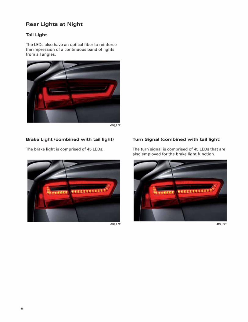
Rear Lights at Night
Tail Light
The LEDs also have an optical fi ber to reinforce
the impression of a continuous band of lights
from all angles.
Brake Light (combined with tail light)
The brake light is comprised of 45 LEDs.
Turn Signal (combined with tail light)
The turn signal is comprised of 45 LEDs that are
also employed for the brake light function.
486_117
486_121486_119

49
Fog Light with Tail and Brake Light
This confi guration ensures that the two lighting
functions can be clearly differentiated. It also
maintains the legally mandated minimum
distance between the brake light and the fog
light.
Light Functions not Illustrated
Backup Light
A 16-watt bulb is used for the backup light.
The backup light function operates only in the
quarter panel light.
486_123
High Mounted Brake Light
The 2012 A6 has a center high-mounted brake
light at the upper edge of the rear window.
This light supplements the brake light function
comprised of 18 LEDs
Light Function Type
Tail light
Brake light
Turn signal
Backup light
High mounted brake light
30x LED
45x LED
45x LED
1x W16W, 16 Watt
18x LED
Rear fog light 1x H21W, 21 Watt
Side marker light 2x LED

Climate Control
50
Overview
Climate Control System Versions
Three-zone and four-zone climate control
systems are available on the 2012 A6.
On the three-zone system, rear passengers can
adjust the temperature via a button located on
the rear center console.
Two humidity sensors, Humidity Sensor in
Fresh Air Intake Duct J657 and Humidity Sensor
G355 are used in both the three- and four-zone
systems.
The four-zone system also has Rear A/C Display
Control Head E265 with the following functions:
– Temperature adjustment
– Fan adjustment
– Separate rear left and right air distribution
adjustment
Three-Zone Climate Control System
ReferenceFor further information about the climate control systems of the 2012 A6, refer to Self-Study Program
990603, The 2012 Audi A7 Occupant Protection, Infotainment, Climate Control, and Head-Up Display.
To provide climate control in the rear, the four-
zone system has air outlets in the B-pillars.
The four-zone climate control system has the
following features:
– Automatic recirculation control by Air Quality
Sensor G238
– Residual heat function
– Separate footwell temperature control
– Glove compartment cooling system
– Three different air conditioning modes: soft,
medium, and intensive
Four-Zone Climate Control System
478_068
Climatronic Control Module J255
Rear upper body vent
478_069Rear A/C Display Control Head E265
Climatronic Control Module J255

Infotainment
51
484_103
Radio RDisplay and Control CAN bus
Digital Sound System Control Module J525DVD Changer R161
Instrument Cluster Control Module J285
Front Information Display Control
Head J685
LIN
MOST bus
Information Electronics Control Module 1 J794
Data Bus On Board Diagnostic Interface J533
Introduction
The 2012 A6 comes equipped with the MMI
Radio plus or the MMI Navigation plus system,
depending on vehicle model level.
484_070
484_067
MMI Radio plus
484_065
484_069
MMI Navigation plus
Topology
The A6 Infotainment control modules
communicate over the MOST bus. This allows
very high data transfer rates.
Picture signals from the back-up camera or DVD
changer are transmitted as FBAS signals to
Information Electronics Control Module 1 J794.

52
Radio Media Center (RMC)
The MMI Radio plus system belongs to the Radio
Media Center infotainment platform.
Depending on equipment level, the Radio
Media Center combines nearly all the hardware
functions of a modern infotainment system in
a single housing, which is the equivalent of a
1-DIN device. The RMC is also central controller
for the infotainment system.
The main difference in the RMC with the third
generation MMI system is that there is no
separate radio control module. The functions
of the radio are integrated into Information
Electronics Control Module 1 J794. On vehicles
with MMI Radio plus, J794 has an additional
audio amplifi er.
Radio diagnosis with the VAS Scan Tool is
done through Address Word 5F — Information
Electronics Control Module 1 J794.
RMC Control Modules
This illustration below shows which control
modules and functions are grouped within
Information Electronics Control Module J749
of the Radio Media Center.
484_067
Front panel of J794 for MMI Radio plus
484_073
Radio control module
CD Player R89
Digital Sound System Control Module J525
Information Electronics Control Module 1 J794
Speech Input Control Module J507
Telephone Transceiver R36
SD card reader
Front Information Display Control Head Control Module J523
External Audi Source Connection (AMI) R199

53
484_067
Front panel of J794 for MMI Radio plus
Speech Dialogue System
MMI Radio plus comes with an integrated speech
dialogue system, which can be used, among
other things, for the hands-free telephone or for
selecting a radio channel. The main functions
of the RMC can be operated by voice control
(for example, fi nd a contact in a directory, dial a
number, etc.).
MMI Radio Plus (RMC)
MMI Radio plus has the following features:
– Two SD card readers
– Integrated six-channel amplifi er for the Audi
Sound System with 180 watts power output
– Bluetooth interface
– Speech dialogue system
– Driver Information System (DIS) with
monochrome screen in the instrument cluster
– Digital satellite radio
– AUX in on center console
– Compatible with optional equipment
– 6.5-inch color display with 400 x 200 pixel
resolution
– Control panel with six freely assignable radio
station keys
– FM tuner with dual diversity
With MMI Radio plus, the CD drive and the SD
card reader support playback of the following
audio fi les:
– MP3
– WMA
– AAC
– WAV
The metadata in these fi les (album, track, artist,
etc.) and the embedded album cover can also be
displayed.
Bluetooth Interface
The MMI Radio for the A6 comes with a
Bluetooth interface, which enables the RMC to
be used for the hands-free telephone and audio
streaming.
The Bluetooth HFP profi le is used for the hands-
free telephone and A2DP for audio streaming.
The AVRCP profi le is used to control the audio
player connected via Bluetooth. The scope of the
control options is dependent upon the device in
use.
484_074
MOST bus
AM/FM1
SDARS
FM2 Display
AMI
Back panel of J794 for MMI Radio plus

54
484_069
Front panel of J794 for MMI Navigation plus
MMI Navigation Plus
The MMI Navigation plus system is identical to
the system of the 2011 A8. It is a third generation
MMI system with the internal designation
MMI3G plus. MMI Navigation plus features the
following:
– 60 GB hard drive (with approximately 20 GB for
Jukebox)
– 3D navigation with 3D city models
– DVD drive
– Two SD card readers (for SDHC cards up to 32
GB in size)
– Premium speech dialogue system
– Radio control module with phase diversity
– Six-channel amplifi er with 180 watts power
output (integrated into the radio control
module)
– 8-inch TFT screen with 800 x 480 pixel
resolution
– Driver information system with 7-inch color
screen in the instrument cluster
– MMI touch
– Bluetooth interface for:
• Hands-free telephone (HFP)
• Audio streaming (A2DP)
The A6 with MMI Navigation plus also includes
the following standard equipment:
– Audi Music Interface
– Audi Connect (WLAN hotspot)
– Digital satellite radio tuner
484_078
MOST bus
Navigation
Telephone
FBASDisplay
AMI
Back panel of J794 for MMI Navigation plus
55
484_079
3D satellite map
484_081
UMTS reception
GSM reception
Settings
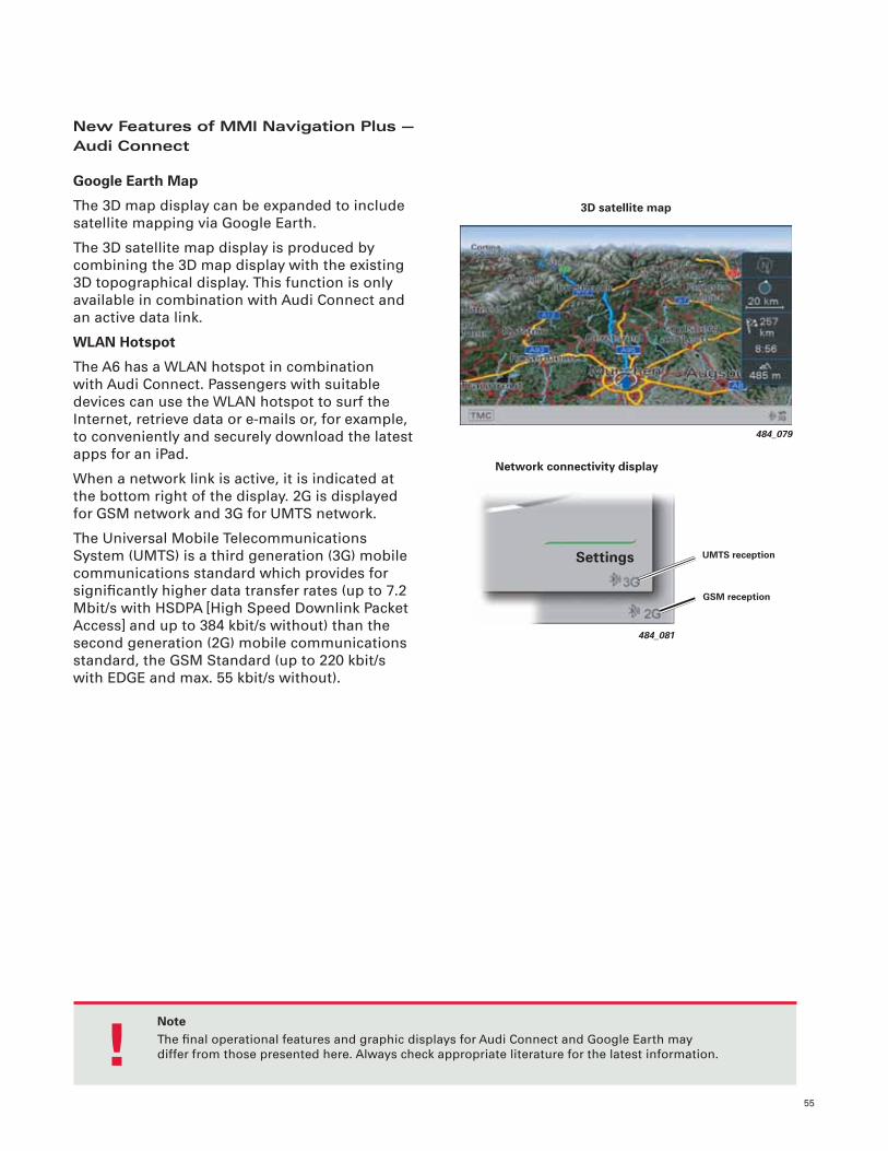
New Features of MMI Navigation Plus — Audi Connect
Google Earth Map
The 3D map display can be expanded to include
satellite mapping via Google Earth.
The 3D satellite map display is produced by
combining the 3D map display with the existing
3D topographical display. This function is only
available in combination with Audi Connect and
an active data link.
WLAN Hotspot
The A6 has a WLAN hotspot in combination
with Audi Connect. Passengers with suitable
devices can use the WLAN hotspot to surf the
Internet, retrieve data or e-mails or, for example,
to conveniently and securely download the latest
apps for an iPad.
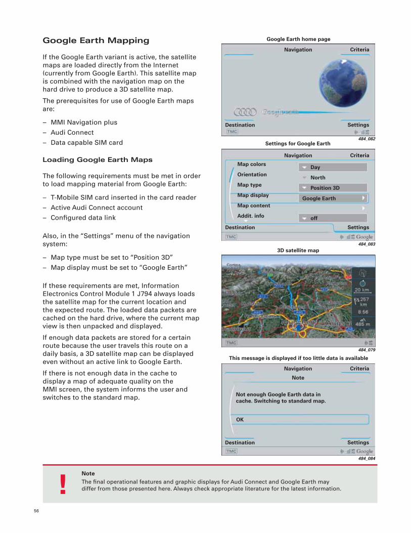
When a network link is active, it is indicated at
the bottom right of the display. 2G is displayed
for GSM network and 3G for UMTS network.
The Universal Mobile Telecommunications
System (UMTS) is a third generation (3G) mobile
communications standard which provides for
signifi cantly higher data transfer rates (up to 7.2
Mbit/s with HSDPA [High Speed Downlink Packet
Access] and up to 384 kbit/s without) than the
second generation (2G) mobile communications
standard, the GSM Standard (up to 220 kbit/s
with EDGE and max. 55 kbit/s without).
Network connectivity display
NoteThe fi nal operational features and graphic displays for Audi Connect and Google Earth may
differ from those presented here. Always check appropriate literature for the latest information. !
56
484_082
Settings
Criteria
Destination
Navigation
Google Earth home page
484_079
3D satellite map
484_084
This message is displayed if too little data is available
Not enough Google Earth data in cache. Switching to standard map.
Settings
Criteria
Destination
Navigation
OK
Note
Google Earth Mapping
If the Google Earth variant is active, the satellite
maps are loaded directly from the Internet
(currently from Google Earth). This satellite map
is combined with the navigation map on the
hard drive to produce a 3D satellite map.
The prerequisites for use of Google Earth maps
are:
– MMI Navigation plus
– Audi Connect
– Data capable SIM card
Loading Google Earth Maps
The following requirements must be met in order
to load mapping material from Google Earth:
– T-Mobile SIM card inserted in the card reader
– Active Audi Connect account
– Confi gured data link
Also, in the “Settings” menu of the navigation
system:
– Map type must be set to “Position 3D”
– Map display must be set to “Google Earth”
If these requirements are met, Information
Electronics Control Module 1 J794 always loads
the satellite map for the current location and
the expected route. The loaded data packets are
cached on the hard drive, where the current map
view is then unpacked and displayed.
If enough data packets are stored for a certain
route because the user travels this route on a
daily basis, a 3D satellite map can be displayed
even without an active link to Google Earth.
If there is not enough data in the cache to
display a map of adequate quality on the
MMI screen, the system informs the user and
switches to the standard map.
484_083
Day
North
Position 3D
Settings for Google Earth
Settings
Criteria
Destination
Navigation
Map colors
Orientation
Map type
Map display
Map content
Addit. info
Google Earth
off
NoteThe fi nal operational features and graphic displays for Audi Connect and Google Earth may
differ from those presented here. Always check appropriate literature for the latest information. !

57
WLAN Hotspot
Wireless high-speed internet access is made
possible via WiFi connectivity technology, which
provides a link between WLAN (wireless local
area network) hotspots and multiple devices.
A hotspot is a location which offers public
Internet access via a wireless network. Unlike
a regular WLAN network, the devices usually
do not have to be linked to one another or
networked. They are linked separately to the
hotspot. Like most public hotspots, Audi also
uses the IEEE802.11b/g wireless standard for
transmitting data.
The UMTS module connects the device to the
Internet via the vehicle’s external aerial. The
UMTS module is built into J794. Maximum
download speed is 7.2 Mbit/s.
The following Internet connectivity requirements
must be met:
– T-Mobile SIM card inserted in the card reader
– Active Audi Connect account
– Confi gured data link
WLAN on the Audi A6
Audi Connect is required to implement the
WLAN hotspot. It transforms the A6 into a full-
fl edged offi ce on wheels. Up to eight devices
(for example, iPads, laptops, PDAs, etc.) can be
linked to the hotspot. The reception range is
confi ned to the interior of the vehicle.
The WLAN hotspot is installed with the following
equipment combination:
– MMI Navigation plus
– Audi Connect
The control module required for the WLAN
hotspot is integrated in Information Electronics
Control Module 1 J794. The hotspot can also be
used for connecting suitable devices via WLAN.
484_085Information Electronics Control Module 1 J794
Worldwide web
Pocket PC
Laptop
iPad
Hotspot module UMTS/GSM module
Schematic diagram of a WLAN hotspot
NoteThe fi nal operational features and graphic displays for Audi Connect and Google Earth may
differ from those presented here. Always check appropriate literature for the latest information. !
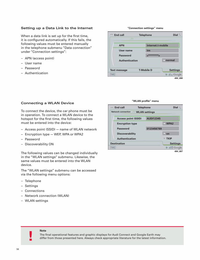
58
Setting up a Data Link to the Internet
When a data link is set up for the fi rst time,
it is confi gured automatically. If this fails, the
following values must be entered manually
in the telephone submenu “Data connection”
under “Connection settings”:
– APN (access point)
– User name
– Password
– Authentication
484_086
internet.t-mobile
tm
<********>
End call
Settings
Dial
Text message
Telephone
APN
User name
Password
Authentication normal
“Connection settings” menu
T-Mobile D
Connecting a WLAN Device
To connect the device, the car phone must be
in operation. To connect a WLAN device to the
hotspot for the fi rst time, the following values
must be entered into the device:
– Access point (SSID) — name of WLAN network
– Encryption type — WEP, WPA or WPA2
– Password
– Discoverability ON
The following values can be changed individually
in the “WLAN settings” submenu. Likewise, the
same values must be entered into the WLAN
device.
The “WLAN settings” submenu can be accessed
via the following menu options:
– Telephone
– Settings
– Connections
– Network connection (WLAN)
– WLAN settings
484_087
SettingsDestination
Access point (SSID)
Encryption type
Password
Discoverability
Authentication
AUDI12345
WPA2
“WLAN profi le” menu
End call DialTelephone
Network connection WLAN settings
TKIP
0123456789
on
NoteThe fi nal operational features and graphic displays for Audi Connect and Google Earth may
differ from those presented here. Always check appropriate literature for the latest information. !
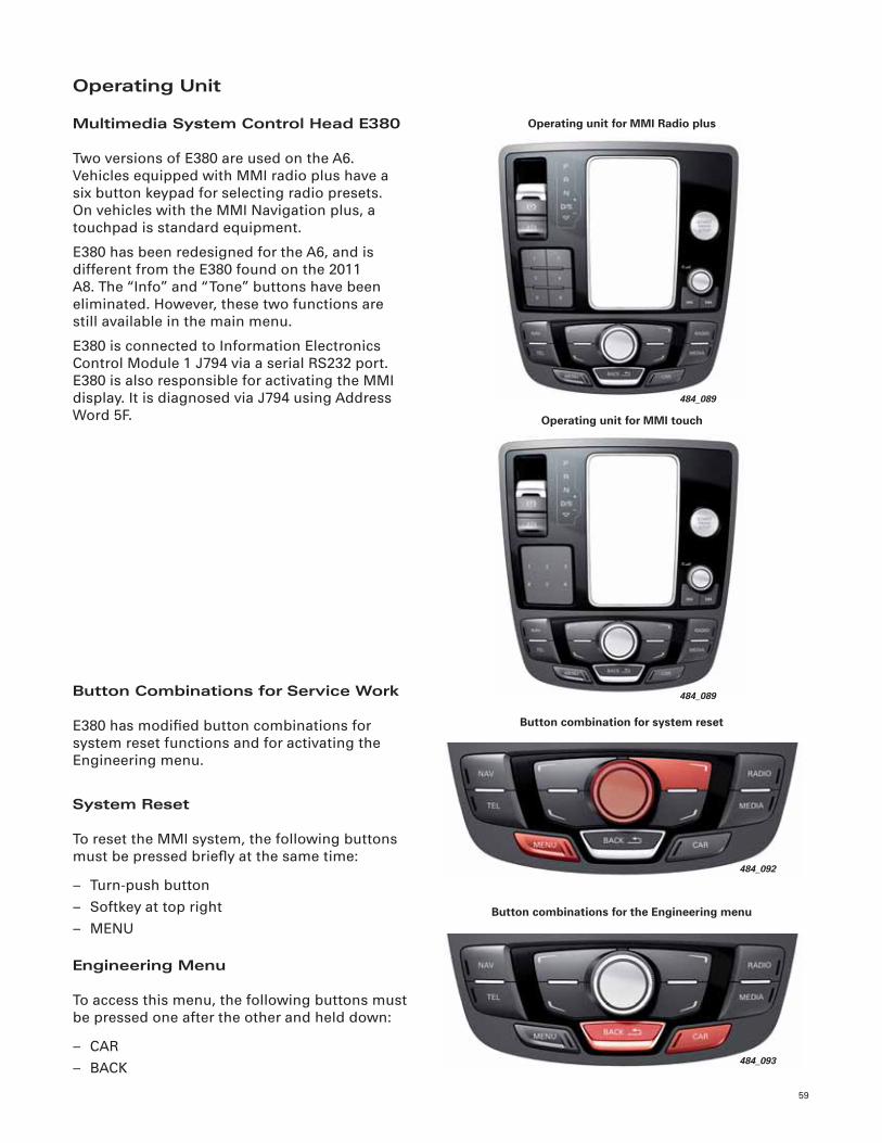
59
Operating Unit
Multimedia System Control Head E380
Two versions of E380 are used on the A6.
Vehicles equipped with MMI radio plus have a
six button keypad for selecting radio presets.
On vehicles with the MMI Navigation plus, a
touchpad is standard equipment.
E380 has been redesigned for the A6, and is
different from the E380 found on the 2011
A8. The “Info” and “Tone” buttons have been
eliminated. However, these two functions are
still available in the main menu.
E380 is connected to Information Electronics
Control Module 1 J794 via a serial RS232 port.
E380 is also responsible for activating the MMI
display. It is diagnosed via J794 using Address
Word 5F.
484_092
Button combination for system reset
484_093
Button combinations for the Engineering menu
484_089
Operating unit for MMI Radio plus
Button Combinations for Service Work
E380 has modifi ed button combinations for
system reset functions and for activating the
Engineering menu.
System Reset
To reset the MMI system, the following buttons
must be pressed briefl y at the same time:
– Turn-push button
– Softkey at top right
– MENU
Engineering Menu
To access this menu, the following buttons must
be pressed one after the other and held down:
– CAR
– BACK
484_089
Operating unit for MMI touch
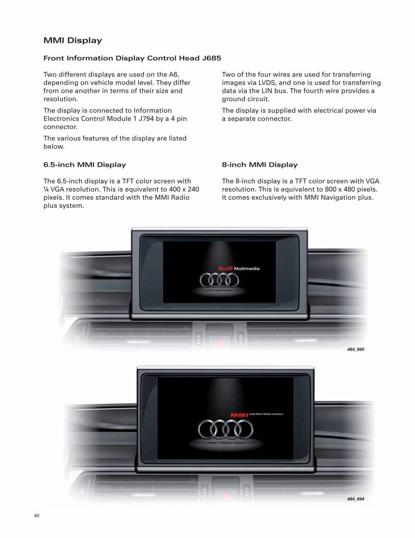
60
MMI Display
Front Information Display Control Head J685
Two of the four wires are used for transferring
images via LVDS, and one is used for transferring
data via the LIN bus. The fourth wire provides a
ground circuit.
The display is supplied with electrical power via
a separate connector.
6.5-inch MMI Display
The 6.5-inch display is a TFT color screen with
¼ VGA resolution. This is equivalent to 400 x 240
pixels. It comes standard with the MMI Radio
plus system.
Two different displays are used on the A6,
depending on vehicle model level. They differ
from one another in terms of their size and
resolution.
The display is connected to Information
Electronics Control Module 1 J794 by a 4 pin
connector.
The various features of the display are listed
below.
484_095
484_094
8-inch MMI Display
The 8-inch display is a TFT color screen with VGA
resolution. This is equivalent to 800 x 480 pixels.
It comes exclusively with MMI Navigation plus.

61
MMI Display Swivel Mechanism
A cable pull drive is used to raise and lower the
MMI display.
The swivel mechanism has the following parts:
– Display Opening/Closing Motor V301
– Display –Open– Stop Switch F330
– Display –Closed– Stop Switch F331
– Cable pull
– Spring tensioning elements
– Guide track
– Driving gear
Activation Mechanism
The motor and both limit switches are activated
and evaluated by Multimedia System Control
Head E380.
Service Position
The display must be placed into a service
position before it can be removed. During this
process, the driving gear is moved to within
a defi ned distance of Display –Closed– Stop
Switch F331
This prevents damage to F331 during removal.
The display is moved into the service position
using Guided Fault Finding.
Operation
When the display is opening, V301 drives the
pulley. The cable is retracted below the driving
gear and unreeled above the driving gear. The
driving gear moves down.
The display mount is fi rmly attached to the
driving gear and is swiveled downward, opening
the display.
Display Opening/Closing Motor V301 stops the
moment the shuttle actuates Display –Open–
Stop Switch F330. The spring in the tensioning
element ensures the cables remain taut. The
pre-tension of the springs also prevents any
rattling noise when the display is open.
Design
484_096
Guide track
Driving gear
Display Opening/Closing Motor V301
Display –Closed– Stop Switch F331
Cable pull
Display –Open– Stop Switch F330
Spring tensioning elements

62
Sound Systems
Three sound systems are offered for the A6.
Sound system availability is vehicle model
dependent. They are:
– The Audi Sound System
– The Bose Surround Sound System
– The Bang & Olufsen Advanced Sound System
486_090
Right Rear Mid-Bass
Speaker R160
Right Effects Speaker R210
Right Front Bass Speaker
R23
Center Speaker R208
Right Front Midrange
Speaker R104
Left Front Treble
Speaker R20
Left Front Bass
Speaker R21
Left Rear Treble
Speaker R14
Right Rear Treble
Speaker R16
Left Front Midrange
Speaker R103
Left Rear Mid-Bass Speaker
R159
Digital Sound System Control
Module J525
Subwoofer R211
Left Effects Speaker R209
Right Front Treble
Speaker R22
Bose Surround Sound System

63
Bang & Olufsen Advanced Sound System
Both amplifi ers supply the loudspeakers with
1300 watts total RMS output power. Retractable
tweeters in the instrument panel set the stage
for a perfect production.
The Bang & Olufsen Advanced Sound System
uses 15 loudspeakers and two amplifi ers.
They create a sense of space resembling the
ambience of a concert hall.
Olufsen
Right Rear Mid-Bass Speaker
R160
Right Front Midrange
Speaker R104
Center Speaker 2 R219
Left Front Bass Speaker
R21
Center Speaker R208
Left Front Treble Speaker R20
Left Front Midrange
Speaker R103
Left Rear Treble Speaker R14
Right Effects Speaker R210
Right Front Treble Speaker
R22Right Front
Bass Speaker R23
Right Rear Treble Speaker
R16
Left Rear Mid-Bass Speaker
R159Left Effects
Speaker R209 Digital Sound System Control
Module J525
Subwoofer R211
Digital Sound System Control Module 2 J787
Bang & Olufsen Sound System

64
Antenna Overview
The antennas for the A6 are located in the rear
window glass and the roof. The amplifi ers for the
rear glass mounted antennas are located in the
trunk lid.
Telephone
SDARS
Navigation
486_091
Roof Antenna R216
486_092
Antenna Amplifi er 2 R11
Antenna Amplifi er R24
FM2 connection
Rear window antennas with amplifi ers
AM antenna
FM1/AM connection
Remote central locking terminal

Head-Up Display
65
Introduction
The term “head-up display” describes optical
systems which project information from various
automotive systems into the driver’s extended
fi eld of vision.
To view this information, the driver does not
have to change their head position signifi cantly
and can continue to focus on the road ahead
while maintaining an upright posture. Since the
driver’s head can remain “up” and need only be
lowered slightly, the system is referred to as a
head-up display.
The use of special windshields on models with
head-up display gives the impression that the
display is not actually in the windshield area, but
at a comfortable distance of 8.2 ft (2.5 m) away
from the driver. The head-up display appears to
hover over the hood.
These benefi ts mean that desired information
can be seen more easily and with greater clarity
than glancing at an instrument cluster. With
head-up display, driver attention to the road
ahead is increased.
Use of head-up display greatly improves
perception of what is happening on the road,
improving overall road safety.
Viewing Advantages of Head-Up Display Over Instrument Cluster Display
– The placement of the head-up display in the
extended fi eld of vision of the driver means
that the driver’s head only needs to be
inclined approximately fi ve to 10 degrees to
see display data. To see similar data on the
instrument cluster display, the driver’s head
needs to be inclined approximately 20–25
degrees.
– As the head-up display can be seen in the
extended fi eld of vision of the driver, the
human eye does not have to adapt to darker
surroundings to register the display content,
unlike a glance at the instrument cluster.
This particularly applies during daylight.
Adaptation of the eyes from bright to dark to
register vehicle parameters and subsequent
adaptation from dark to bright can be avoided.
– As the head-up display is perceived at a
distance of approximately 6.5 ft – 8.2 ft
(1.9 m – 2.4 m) away from the driver, the time
the eye needs to focus is signifi cantly lower
than glancing periodically at an instrument
cluster.
482_002
50mph

66
Display Information
Content of the head-up display has been
restricted to the most important vehicle
parameters. Current vehicle speed is always
shown. It cannot be deactivated in the MMI.
Other display content is only shown if activated
in the MMI. Content can be activated in the MMI
at the menu option “Head-up Display”, then
menu “Display Content”.
Other content is only displayed temporarily, for
example warnings, or modifi ed system settings.
The display can show the following content:
Current Vehicle Speed
Current vehicle speed is the only vehicle variable
that is always displayed. This display cannot be
deactivated by the driver.
Current ACC Set Speed
The set control speed of the ACC appears
temporarily in the head-up display if modifi ed.
The “ACC / Audi active lane assist” display
content must be activated in the MMI.482_006
62mph
50mph
482_003
50mph
482_004
50mph
482_005
50mph
Navigation Information
“Navigation Information” is only displayed
when the route guidance function is active. This
information must be activated in the MMI.
Combined Display of ACCand Audi Active Lane Assist
The “ACC/Audi active lane assist” display content
must be activated in the MMI.

67
Current ACC Control Distance
This display appears for a short period of time
if a change is made to the control distance for
ACC.
Audi Night Vision Assist Warning
Audi Night Vision Assist warnings can also be
shown on the head-up display, once activated in
the MMI.
482_007
50mph
482_010
50mph
482_011
50mph
Red Warning Symbols
If red warning signals appear in the instrument
cluster, they also appear on the head-up display.
The display of red warning symbols cannot be
deactivated, and are only displayed briefl y. When
red warning signals are displayed, all other
content is suppressed except vehicle speed.

68
Windshield Projection Head Up Display Control Module J898
The central component of the head-up display
system is J898. It contains all the optical,
mechanical, and electrical components required
for the system.
J898 is mounted in the instrument panel, directly
in front of the instrument cluster.
482_012
NoteIf J898 is defective, the complete unit must be replaced. Replacement requires the removal of the
windshield. For more information, refer to current technical literature.!
482_013
Windshield Project Head Up Display Control Module J898

69
Optical System
The head-up display is generated by backlighting
with 15 LEDs a high resolution TFT display, which
is a matrix of Thin Film Transistors.
The display’s function is similar to that of a
slide projector. Light rays are projected via two
defl ection mirrors onto the windshield. One of
the two mirrors is adjustable and is used for
height adjustment of the display. This adapts
the position of the head-up image to the seating
position or body size of the driver.
The mirrors also correct any image distortion
caused by curvature of the windshield.
The light intensity of the displayed image is
continuously adapted to current ambient lighting
conditions. To do this, Windshield Projection
Head Up Display Control Module J898 evaluates
luminosity values from Rain/Light Recognition
Sensor G397.
The driver can adjust the brightness of the
display according to their needs. This is done
through the MMI and the system controls
located on the vehicle light switch.
The light intensity is confi gured so the display
also remains easily legible in direct sunlight.
482_014
Adjustable mirror
Lighting unit of the head-up
display
Windshield Projection Head
Up Display Control Module J898
Non-adjustable mirror
High-resolution TFT display
ReferenceThe operation and calibration of the head-up display system for the 2012 A6 is the same as for the 2012 A7.
For more details, refer to Self-Study Program 990603, The 2012 Audi A7 Occupant Protection, Infotainment,
Climate Control, and Head-Up Display.

70
482_017
“terminal 30”
“terminal 31”
Display and Control CANWindshield Projection Head Up
Display Control Module J898
Windshield
The windshield is an important optical
component of the head-up display. Because the
display image is also refl ected by the windshield,
its function represents a third mirror.
A standard windshield can create a disruptive
double image.
The windshield of a vehicle with the head-up
display differs from a conventional windshield in
that the PVB foil (polyvinyl butyral) between the
two fl at glass panes of a head-up windshield is
not a constant thickness.
A head-up windshield has a slight wedge shape,
so the thickness of the windshield increases
slightly in an upward direction. This wedge
shape eliminates the potential for double
images.
The tolerances for windshield installation are
very tight for a vehicle with head-up display.
There are six electrical connections at the control
module:
– Two lines for “terminal 30”
– Two lines for “terminal 31”
– Two lines for the Display and Control CAN
Electrical System
Windshield Projection Head Up Display Control
Module J898 communicates with other control
modules over the Display and Control CAN.
It is accessed with the VAS Scan Tool through
Address Word 82.
482_016
Windshield of a vehicle without head-up display
PVB foilFlat glass panes
482_015
PVB foilFlat glass panes
Windshield of a vehicle with head-up display

Notes
71

Self Study Programs for the 2012 Audi A7
72
The 2012 Audi A7 Vehicle Introduction
Self-Study Program 990203
The 2012 Audi A7 Running Gear and Suspension Systems
Self-Study Program 990303
The 2012 Audi A7Onboard Power Supply and Networking
Self-Study Program 990403
The 2012 Audi A7 Convenience Electronicsand Audi Active Lane Assist
Self-Study Program 990503
SSP 990203 The 2012 Audi A7Vehicle Introduction
– Body
– Occupant Protection
– Engine
– Power Transmission
– Suspension System
– Electrical System
– Climate Control
– Infotainment
SSP 990303 The 2012 Audi A7Running Gear and Suspension Systems
– Axles and Wheel Alignment
– Adaptive Air Suspension
– Steering System
– Electromechanical Steering
– Brake System
SSP 990403 The 2012 Audi A7Onboard Power Supply and Networking
– Power Supply
– Networking
– Control Modules
– Exterior Lighting
SSP 990503 The 2012 Audi A7Convenience Electronics andAudi Active Lane Assist
– Topology
– Convenience Electronics
– Audi Active Lane Assist
SSP 990603 The 2012 Audi A7Occupant Protection, Infotainment,Climate Control, and Head-Up Display
– Occupant Protection
– Audi pre sense
– Infotainment
– Air Conditioning
– Seat System
– Head-Up Display
The 2012 Audi A7 Occupant Protection, Infotainment, Climate Control, andHead-Up Display
Self-Study Program 990603
– ESP
– Sensor Electronics Control Module J849
– Adaptive Cruise Control (ACC)
– Wheels and Tires
– Tire Pressure Monitoring (TPMS)

Knowledge Assessment
73
An on-line Knowledge Assessment (exam) is available for this Self-Study Program.
The Knowledge Assessment is required for Certifi cation.
You can fi nd this Knowledge Assessment at:
www.accessaudi.com
From the accessaudi.com Homepage:
– Click on the “ACADEMY” tab
– Click on the “Academy Site” link
– Click on the “CRC/Certifi cation” link
– Click on Course Catalog and select “990613 — The 2012 Audi A6 Vehicle Introduction”
For assistance please call:
Audi Academy
Certifi cation Resource Center (CRC)
1-877-283-4562
(8:00 a.m. to 8:00 p.m. EST)
Or you may send an email to:
Thank you for reading this Self-Study Program and taking the assessment.

990613
All rights reserved.Technical specifi cations subject to change without notice.
Audi of America, LLC2200 Ferdinand Porsche DriveHerndon, VA 20171