the 3d geometry reconstruction of a scaled axial blade by
TRANSCRIPT

ISSN 1453 – 7303 “HIDRAULICA” (No. 4/2018) Magazine of Hydraulics, Pneumatics, Tribology, Ecology, Sensorics, Mechatronics
12
The 3D Geometry Reconstruction of a Scaled Axial Blade by Photogrammetry
Prof. PhD. Eng. Dorian NEDELCU1, PhD. Student Eng. Sorin-Laurenţiu BOGDAN2, Assoc. Prof. PhD. Eng. Ioan PĂDUREAN3
1 “Eftimie Murgu” University of Reşiţa, [email protected]
2 “Eftimie Murgu” University of Reşiţa, [email protected]
3 "POLITEHNICA" University of Timișoara, [email protected]
Abstract: The paper illustrates the Reverse Engineering of an axial blade geometry, who was scanned through Photogrammetry technique and processed with the following software packages: Agisoft Photoscan and Geomagic Design X; the solid geometry and the drawing of the blade were generating using the SolidWorks software. The 3D blade geometry was compared with the blade mesh generated in Geomagic Design X based on point cloud obtained in Agisoft Photoscan software. Ultimately, three plane intersections of the blade were compared with measured points on the real blade on CNC machine.
Keywords: Reverse Engineering, Photogrammetry, Turbine, Axial Blade
1. Introduction
As it can be noticed from regional preoccupation in the field, but also by extrapolation as a national and worldwide approach, the exploitation at maximum efficiency of the water courses hydropower potential by developing viable small hydroelectric plants [1], as also the efficiency mounting for existing peak hydroelectric arrangements by acquiring pumped-storage hydroelectric power plants [2], are directly related to the optimization of the engaged hydropower machines, a goal that can be achieved by a high precision design of the axial turbine’s blades. Using the Reverse Engineering technology, the geometry of a scaled blade of axial type with the mass equal to 0.528 kg, Fig. 1, will be reconstructed by following the next steps:
o 3D scanning of the blade using Photogrammetry and the Agisoft Photoscan software; o the blade reconstruction using the Geomagic Design X and SolidWorks software packages.
Fig. 1. The axial blade
2. Acquisition of the images
The acquisition of photographic images was done with the NIKON D610 camera positioned on a tripod, generating 78 snapshots from different successive angles, covering 720 degrees on two levels of the blade periphery, Fig. 2. The following shooting parameters were used: Focal length 50, F-stop F / 11, ISO 1600, Shutter 1/125. Contactless scanners and photo devices use light in

ISSN 1453 – 7303 “HIDRAULICA” (No. 4/2018) Magazine of Hydraulics, Pneumatics, Tribology, Ecology, Sensorics, Mechatronics
13
capturing data. This creates problems when light hits glossy surfaces, so the blade surfaces must be prepared before scanning, temporarily applying a fine layer of powder, Fig. 2.
Fig. 2. The images sequence of the scaled axial blade
3. Cloud Point Generation in Agisoft Photoscan software
The import of photos into the Agisoft Photoscan software is shown in Fig. 3. The sparse cloud of 169,445 points is shown in Fig. 4; the dense cloud of 1,780,197 points is shown in Fig. 5. The point cloud calibration (scaling the geometry to real values) based on known distances is shown in Fig. 6. The dense point cloud generated in the Agisoft Photoscan software was exported in OBJ format to be imported into the Geomagic Design X software.

ISSN 1453 – 7303 “HIDRAULICA” (No. 4/2018) Magazine of Hydraulics, Pneumatics, Tribology, Ecology, Sensorics, Mechatronics
14
Fig. 3. Images inserted into the Agisoft Photoscan software
Fig. 4. Images aligned in Agisoft Photoscan and sparse cloud generation of 169,445 points
Fig. 5. Dense cloud generation of 1,780,197 points in Agisoft Photoscan software

ISSN 1453 – 7303 “HIDRAULICA” (No. 4/2018) Magazine of Hydraulics, Pneumatics, Tribology, Ecology, Sensorics, Mechatronics
15
Fig. 6. Points cloud calibrating in Agisoft Photoscan software
4. Generate the blade profiles in Geomagic Design X software
The following stages are required to generate the blade profiles: o the dense cloud import (1,780,197 points) into Geomagic Design X, Fig. 7; o generate the mesh of the points cloud; at this stage the software generates a network of
triangles similar to meshing in the finite element analysis; for this blade 863,228 triangles were generated, Fig. 8;
o the generation of 6 profiles in Geomagic Design X, resulted from the intersection of the mesh with 6 cylinders with the following imposed radii: 92, 107, 122, 137, 152, 167 mm; also, the characteristic circles of the blade trunnion have been generated, Fig. 9;
o export the 6 intersection profiles and trunnion circles to SolidWorks.
Fig. 7. Points cloud imported in Geomagic Design X software

ISSN 1453 – 7303 “HIDRAULICA” (No. 4/2018) Magazine of Hydraulics, Pneumatics, Tribology, Ecology, Sensorics, Mechatronics
16
Fig. 8. The mesh of the points cloud imported in Geomagic Design X software
Fig. 9. The six profiles of the blade generated in Geomagic Design X software
5. Generate the blade geometry in SolidWorks software
The intersection profiles and the trunnion circles were imported into SolidWorks software. The intersection of scaled blade geometry with the cylinders can generate profiles with a slightly irregular shape, especially in the leading-edge area. This is a common problem for scanners, which can generate errors in areas with lower brightness, such as chamfers, fillets, holes, threads or the leading edge, as is the case here, as shown in Fig. 10.
Fig. 10. The profiles imported in SolidWorks software with leading edge irregularities
ISSN 1453 – 7303 “HIDRAULICA” (No. 4/2018) Magazine of Hydraulics, Pneumatics, Tribology, Ecology, Sensorics, Mechatronics
17
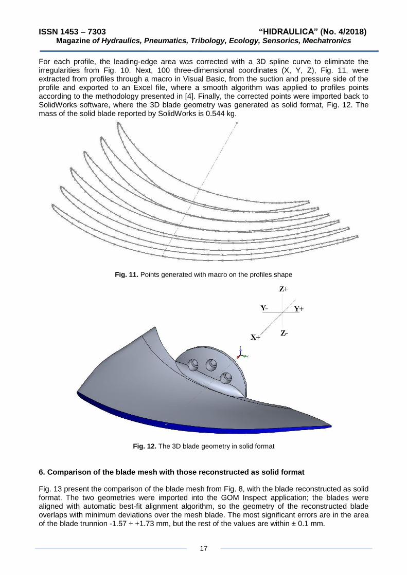
For each profile, the leading-edge area was corrected with a 3D spline curve to eliminate the irregularities from Fig. 10. Next, 100 three-dimensional coordinates (X, Y, Z), Fig. 11, were extracted from profiles through a macro in Visual Basic, from the suction and pressure side of the profile and exported to an Excel file, where a smooth algorithm was applied to profiles points according to the methodology presented in [4]. Finally, the corrected points were imported back to SolidWorks software, where the 3D blade geometry was generated as solid format, Fig. 12. The mass of the solid blade reported by SolidWorks is 0.544 kg.
Fig. 11. Points generated with macro on the profiles shape
Fig. 12. The 3D blade geometry in solid format
6. Comparison of the blade mesh with those reconstructed as solid format
Fig. 13 present the comparison of the blade mesh from Fig. 8, with the blade reconstructed as solid format. The two geometries were imported into the GOM Inspect application; the blades were aligned with automatic best-fit alignment algorithm, so the geometry of the reconstructed blade overlaps with minimum deviations over the mesh blade. The most significant errors are in the area of the blade trunnion -1.57 ÷ +1.73 mm, but the rest of the values are within ± 0.1 mm.

ISSN 1453 – 7303 “HIDRAULICA” (No. 4/2018) Magazine of Hydraulics, Pneumatics, Tribology, Ecology, Sensorics, Mechatronics
18
Fig. 13. The mesh comparison of the blade with those in solid format
7. Comparison of the measured blade with those reconstructed as solid in SolidWorks
To verify the accuracy of the blade reconstruction, it was measured on the DMF 180 DECKEL MAHO CNC machine, Fig. 14. The measurements were performed on the suction side, Fig. 15, and pressure side, Fig. 16, at three planes placed at X = 40, 60 and 80 mm from the trunnion end plane. The comparison is presented in Fig. 17, 18 and 19. These figures show a correct overlap of the comparison curves, small deviations due to cumulative scan errors, solid geometry generation and measurement. These errors also include the small changes applied to the theoretical profiles due to their smoothing operation. The minimum and maximum deviations range for the plane placed at X = 40, 60 and 80 mm were -0.33018 / +0.094484, -0.37405 / +0.29926 and -0.04589 / +0.476279 respectively.
Fig. 14. CNC machine DMF 180 DECKEL MAHO

ISSN 1453 – 7303 “HIDRAULICA” (No. 4/2018) Magazine of Hydraulics, Pneumatics, Tribology, Ecology, Sensorics, Mechatronics
19
Fig. 15. Measuring the suction side of the blade
Fig. 16. Measuring the pressure side of the blade
8. Conclusions
Scanning geometry is a laborious task, necessary but not enough. The result of the scan is a point cloud of three-dimensional coordinates. To use geometry in computer aided design applications is required to move to a higher level, like cloud points transformation into surface or solid geometry. That's it can only be done through specialized applications, like Geomagic Design X and/or SolidWorks. The objective of the paper is to describe the reverse engineering stages to transform a real blade object into a virtual geometry, using the Photogrammetry techniques. For the axial blade, it was necessary to smooth the profiles to attenuate the scanning errors, especially those in the leading-edge area. From the comparison of point cloud mesh with the blade reconstructed in SolidWorks, it was concluded that the largest errors occurred in the 1.55 ÷ +1.73 mm range at the blade trunnion, but most of the values were included within ± 0,1 mm. From the measurements made on the real blade, the suction and pressure side deviations of the reconstructed blade fall within the deviations range between a minimum of -0.37405 and a maximum of +0.476279 mm.

ISSN 1453 – 7303 “HIDRAULICA” (No. 4/2018) Magazine of Hydraulics, Pneumatics, Tribology, Ecology, Sensorics, Mechatronics
20
Fig. 17. The points comparison of the blade at X=40 mm plane
Fig. 18. The points comparison of the blade at X=60 mm plane
Fig. 19. The points comparison of the blade at X=80 mm plane

ISSN 1453 – 7303 “HIDRAULICA” (No. 4/2018) Magazine of Hydraulics, Pneumatics, Tribology, Ecology, Sensorics, Mechatronics
21
Acknowledgments
This paper was supported by “Eftimie Murgu” University of Reşiţa, “Traian Vuia” Square, No. 1-4, 320085, Caraş-Severin county, Reşiţa, Romania.
References
[1] Popescu-Buşan, A.I., Gh. Lazăr, A.T. Constantin, and Ş.V. Nicoară. „Water Flow Transition on a Hydropower Virtually Developed Sector of Bârzava River in the Town of Reșița”, HIDRAULICA No. 3/2018 - Magazine of Hydraulics, Pneumatics, Tribology, Ecology, Sensorics, Mechatronics, pg.46-55, ISSN 1453 – 7303, Bucharest.
[2] Constantin, A.T., I. David, A. Chebuţiu, Ş.V. Nicoară, and M. Vişescu. „The possibility of fitting a pumped storage plant within the complex water development on upper Bârzava, Romania”, Paper presented at the 25th IAHR Symposium on Hydraulic Machinery and Systems, 20–24 September 2010 'Politehnica' University of Timişoara, Romania, IOP Conference Series: Earth and Environmental Science, Volume 12, No.1, 10.1088/1755-1315/12/1/012109, 8 pag, 2010.
[3] Agisoft LLC. “Fully automated professional photogrammetric kit”, Accessed October 21, 2018, http://www.agisoft.com/pdf/photoscan_presentation.pdf
[4] Bogdan, Sorin-Laurenţiu, Dorian Nedelcu, and Ioan Pădurean. “Determining the geometric parameters of a blade runner that has a geometry obtained through the Photogrammetry technique.” Paper presented at the 10th International Conference on Machine and Industrial Design in Mechanical Engineering Novi Sad, Serbia, June 6-8, 2018, http://iopscience.iop.org/article/10.1088/1757-899X/393/1/012127.