the accumulating case - control design
TRANSCRIPT

JUL
Y 2
01
9
NETWORK DIAGNOSTICS
WATCH COLLABORATION
GROW
HOW PRECISE IS PRECISION?
The accumulating case for deterministic control
Time-sensitive networks have many parts under development with some starting to emerge as real products, but the industrial specifi cations will need a few years to mature
CD1907_01_Cover2.indd 1 7/8/19 6:21 PM

the #1 value in automationOrder Today, Ships Today!
* See our Web site for details and restrictions. © Copyright 2019 AutomationDirect, Cumming, GA USA. All rights reserved. 1-800-633-0405
“We found the CLICK PLC from AutomationDirect to be a reliable, easy-to-use, I/O interface for our machines. We replaced our bulky, aging, relay circuit boards and ribbon cable PC connections with smaller, more a� ordable, Ethernet-capable CLICK PLCs. Besides their PLCs, AutomationDirect’s fast, same-day shipping and easy ordering are an added plus for us.” - Jesus Chavez
At AutomationDirect, customer satisfaction is priorityone and we are continually expanding our off ering oflow-cost industrial control products to satisfy a wide range of applications. Our CLICK PLC line was designed to provide simple control solutions and is perfect for small systems or even relay replacement. With hardware starting at only $69.00 and FREE straightforward software, CLICK PLCs will be your go-to choice when time and cost savings are imperative. www.CLICKPLCS.comwww.CLICKPLCS.com
“We found the CLICK PLC from AutomationDirect to be a
Jesus ChavezService and Test EngineerVacuum Technology Inc.
For over 30 years Vacuum Technology Incorporated has focused on developing practical, aff ordable, and custom-tailored solutions for industrial vacuum/ leak testing applications worldwide.
www.vacuumtechnology.com
Your Success is Our SuccessAutomationDirect is your trusted source for cost-effective control solutions
1907-ControlDesign-VTI_CLICK-MAG.indd 1 6/17/2019 12:13:58 PM
CD1907_FPA.indd 2 7/8/19 6:28 PM

seweurodrive.com / 864-439-7537
Need experience?Problem: You can’t recruit or retain
experienced motion control engineers.
Solution: Contact an automation
specialist at SEW-EURODRIVE. Using the
latest innovation, we provide a complete
package from start to finish, including
project planning, design, components,
software, commissioning, and worldwide
support.
Think of our specialists as an extension
of your staff . . .
CD1907_FPA.indd 3 7/8/19 6:29 PM

CD1907_FPA.indd 4 7/8/19 6:29 PM

FEATUREScover story
The accumulating case for deterministic controlTime-sensitive networks have many parts under development with some starting to emerge as real
products, but the industrial speci�cations will need a few years to mature
Dave Perkon, technical editor
26
controllers
How to get a boat in the waterWith the proper tension,
the dual-point davit system,
mounted to large vessels,
can get boats into and out
of rough water without
making waves
Tim Rogers, Systems Interface
32servos
Reduced wear from tensioned linear guidesHigh-performance carbide
metal machine makes for
shorter cutting times and
higher saw-blade service lives
Matthias Eigbrecht,
Kasto Maschinenbau
36product roundup
Where the work gets doneEnclosures and workstations
protect and enable
machinery and operators
41
CONTROL DESIGN, (ISSN: 1094-3366) is published 12 times a year by Putman Media, 1501 E. Woodfield Rd., Suite 400N, Schaumburg, Illinois 60173. (Phone 630/467-1300; Fax 630/467-1124.) Periodical postage paid at Schaumburg, IL, and at additional mailing offices. Address all correspondence to Editorial and Executive Offices, same address. Printed in the United States. ©Putman Media 2019. All rights reserved. The contents of this publication should not be reproduced in whole or part without consent of the copyright owner. POSTMASTER: Please send change of address to Putman Media, PO Box 1888, Cedar Rapids IA 52406-1888; SUBSCRIPTIONS: To change or cancel a subscription, email [email protected] or call 1-800-553-8878 ext. 5020. To non-qualified subscribers in the United States and its possessions, subscriptions are $96.00 per year. Single copies are $15. International subscriptions are accepted at $200 (Airmail only.) Putman Media also publishes CHEMICAL PROCESSING, CONTROL, FOOD PROCESSING, PHARMA MANUFACTURING, PLANT SERVICES, SMART INDUSTRY and THE JOURNAL. CONTROL DESIGN assumes no responsibility for validity of claims in items reported. Canada Post International Publications Mail Product Sales Agreement No. 40028661. Canadian Mail Distributor information: World Distribution Services, Inc., Station A, PO Box 54, Windsor, Ontario, Canada N9A 6J5. Printed in the United States.
table of contentsVolume 23, No. 7
ControlDesign.com / July 2019 / 5
motion control
What is the point of precision?How to clarify the meaning
of precision for better
understanding of motion
Bill Hennessey, Alio Industries
38
CD1907_05_07_TOC.indd 5 7/9/19 3:19 PM

© Allied Electronics & Automation, 2019
1.800.433.5700 alliedelec.comFill your cabinet at
We stock 99% of the components you need for inside and outside the
cabinet. Shop, build, and deliver – quickly and effi ciently.
Build a Better Control Cabinet
We stock 99% of the components you need for inside and outside the
cabinet. Shop, build, and deliver – quickly and effi ciently.
Build a Better Control Cabinet
APR19 Schneider-Control Cabinet Ad (CD).indd 1 3/15/19 3:10 PMCD1907_FPA.indd 6 7/8/19 6:29 PM

For additional information, please contact Foster Printing Service, the official reprint provider for Control Design.
PMS 370 C
C: 60M: 0Y: 100K: 28
Call 866.879.9144 or [email protected]
REPRINTS ARE IDEAL FOR:
n New Product Announcements
n Sales Aid For Your Field Force
n PR Materials & Media Kits
n Direct Mail Enclosures
n Customer & Prospect Communications/Presentations
n Trade Shows/Promotional Events
n Conferences & Speaking Engagements
n Recruitment & Training Packages
Use reprints to maximize
your marketing initiatives and
strengthen your brand’s value.
Reprints are a simple way to put information directly into the hands of
your target audience. Having been featured in a well-respected publication
adds the credibility of a third-party endorsement to your message.
CUSTOM REPRINTS
9 editor’s page
Grow your own cloud solutionMike Bacidore, editor in chief
11 live wire
How special is a controls engineer?Dave Perkon, technical editor
12 embedded intelligence
How to diagnose network issuesJeremy Pollard, CET
13 technology trends
Collaborative plusRick Rice, contributing editor
15 indiscrete
The birth of an alarm lifecycle
PCB makers
GOP reps call for tari� s against China
43 real answers
How to size motors properly
47 product showcase
50 automation basics
Be gentle and accurate with linear motionDave Perkon, technical editor
COLUMNS
Allied Electronics and Automation ................6
AutomationDirect.................................................2
Beckho� Automation .........................................4
Bimba ........................................................................8
Digi-Key Corporation ...........................................2
Endress+Hauser ................................................10
Hammond Manufacturing ..............................23
icotek North America .......................................29
MTS Systems ......................................................14
Pepperl+Fuchs ...................................................19
Sealevel Systems ..............................................21
SEW-Eurodrive .......................................................3
Telemecanique Sensors .................................17
ad index
ControlDesign.com / July 2019 / 7
table of contentsVolume 23, No. 7
CD1907_05_07_TOC.indd 7 7/10/19 9:21 AM
More NFPA Actuator OptionsThan Ever BeforeMore NFPA Actuator OptionsThan Ever Before
The NFPA Actuatorfamily is GROWING
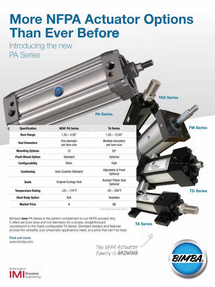
Bimba’s new PA Series is the perfect complement to our NFPA actuator line.It offers set bore sizes and rod diameters for a simple, straightforward counterpoint to the highly con� gurable TA Series. Standard designs and features provide the versatility your pneumatic applications need, at a price that can’t be beat.
Find out morewww.bimba.com
Specifi cation NEW! PA Series TA Series
Bore Range 1.50 – 4.00” 1.50 – 12.00”
Rod DiametersOne diameter per bore size
Multiple diameters per bore size
Mounting Options 12 20*
Flush Mount Option Standard Optional
Confi gurability Basic High
Cushioning Auto-Cushion Standard Adjustable & Fixed Optional
Seals Original Ecology Seal Bumper Piston SealOptional
Temperature Rating +25 – 175°F -20 – 200°F
Steel Body Option N/A Available
Market Price $ $$*with TAS steel body option
TAS Series
FM Series
TD Series
TA Series
PA Series
Introducing the new PA Series
BIM-13642 Bimba Resizes 2019_Control Design_New PA_060119.indd 1 5/15/19 1:08 PMCD1907_FPA.indd 8 7/8/19 6:29 PM
ControlDesign.com / July 2019 / 9
SOMETIMES THE BEST ideas are developed internally. By leveraging cloud-based analytic
technologies from Honeywell Connected Plant (HCP), a six-month internal initiative
boosted productivity of machinery and processes running within Honeywell’s own Perfor-
mance Materials and Technologies (PMT) division. The pilot program increased revenue
and capacity by more than 2% at the PMT plant in Orange, Texas, demonstrating the value
that today’s cloud analytics can provide toward recognizing hidden asset performance
degradation and how assets interact with the processes they serve.
“We make low-density polyethylene,” said Will Olp, manufacturing director of the
additives-and-chemicals PMT, in his presentation at Honeywell Users Group Americas in
Dallas. “We were having more unplanned downtime than business could support.”
The plant had experienced several unplanned shutdowns over 24 months, an esti-
mated $20 million negative impact,
explained Olp. Performance analysis
and reporting was lagging, manually
gathered biweekly. Maintenance was
highly reactive, repeatedly �nding
shutdowns were avoidable. And
communication paths between engi-
neering and reliability/maintenance
were inef�cient.
“The plant incurred several costly unplanned shutdowns,” explained Olp. “There were
myriad operational challenges and worn plant infrastructure. We didn’t want to wait for
the engineers to do the analysis. We were able to take the process information and apply
it to the algorithms and data that were being streamed into the cloud. I started this pro-
cess in May 2018, and we had a solution in place in September.”
The project team combined reliability engineers, process engineers and operators.
“Within Asset Sentinel, they’re now putting in what the root cause was,” explained Olp,
“in addition to creating the algorithm from the data in the historian. We have 28 assets
con�gured and 58 measured KPI sentinels. Site knowledge has been captured into it.”
The process and asset monitoring data streams are uni�ed into a single data-processing
scheme. At the same time a duplicate stream is being sent to the cloud.
The plant’s monitored equipment included reciprocating compressors, heat exchang-
ers, boilers, reactors, off-gas spray columns, binary columns and deodorizers. Four areas
of contribution came from the heat exchangers, deodorizers, boilers and an unidenti�ed
trade-secret asset.
While a 2.2% increase in revenue and 2.2% additional capacity were realized in six
months, �nancial projections indicate breakeven in just 1.1 years annualized.
Grow your own cloud solutioneditorial teameditor in chief
Mike [email protected]
technical editor
Dave [email protected]
digital managing editor
Christopher [email protected]
contributing editor
Rick [email protected]
contributing editor
editorial assistant
Lori [email protected]
columnist
Jeremy [email protected]
design/productionsenior production manager
Anetta Gauthier
senior art director
Derek Chamberlain
subscriptionscustomer service
800-553-8878
circulation Air & Gas Compressors 553
Engineering & Systems
Integration Services 11,547
Engines & Turbines 1,025
Food Products Machinery 1,569
Industrial Fans, Blowers
& Air Purification Equipment 526
Industrial Heating, Refrigeration
& Air Conditioning Equipment 1,139
Industrial Process Furnaces & Ovens 472
Machine Tools 2,110
Materials Handling, Conveyors
& Conveying Equipment 1,507
Metalworking Machinery 2,600
Mining Machinery & Equipment 510
Oil & Gas Field Machinery & Equipment 1,187
Packaging Machinery 906
Paper Industries Machinery 312
Printing Trades Machinery & Equipment 441
Pumps & Pumping Equipment 891
Rolling Mill Machinery & Equipment 157
Semiconductor Manufacturing
Machinery 817
Textile Machinery 172
Woodworking Machinery 274
Other Industries & Special Industrial
Machinery & Equipment NEC 11,305
TOTAL 40,020
1501 E. Woodfield Rd., Suite 400N Schaumburg, Illinois 60173
630/467-1300 Fax: 630/467-1124
In Memory of Julie Cappelletti-Lange, Vice President 1984-2012
Mike Bacidoreeditor in [email protected]
editor’s page
Communication paths between engineering and reliability/
maintenance were inef�cient.
CD1907_09_Edit.indd 9 7/9/19 3:25 PM

Integrating a complete shopping experience into our website underlines our goal to help streamline your procurement processes and to improve your buying experience - both online and offline.
Introducing new possibilities on Endress.com
Set up your account and start shopping today!www.us.endress.com/e-commerce
DIGITAL+PERSONALNew possibilities, new experiences
Complete e-commerce functionality now on Endress.com
CD1907_FPA.indd 10 7/8/19 6:29 PM
SEASONED SENIOR CONTROLS engineers are of great value to
just about any machine builder, system integrator, engineering
� rm or manufacturing facility, and they are harder and harder
to come by lately.
Many of these facilities would be happy to hire controls person-
nel with even basic troubleshooting skills, with the hope that they
can quickly learn what is necessary to support the machines.
With the hardware advancements in automation, the many
industrial protocols and controllers in use and the complexity
of machine applications increasing,
should the controls engineer learn to
support and program everything on
the plant � oor, or should he or she spe-
cialize? The answer is every controls
engineer should master the basics and
then pick a specialty to be ef� cient at
because you cannot know everything.
Of course, some controls engineers will want to know ev-
erything. Your co-workers know who you are—for good and
possibly bad reasons.
In a small operation, an overworked, one-man show is often
all that is available. That’s all good until vacation time. And,
as the size of the operation or system complexity increases,
several specialists, available through both internal and external
sources, may be better.
However, starting at the basics, all controls engineers should
understand the National Electric Code (NEC) and the computer-
aided design (CAD) practices used to implement the NEC as it
relates to industrial automation. The skills to create an electri-
cal design schematic and then use it to build a control panel
and troubleshoot machine power distribution, I/O devices and
related electrical equipment are a must for a controls engineer.
Pneumatic circuit design skills are a must, as well. The selec-
tion, design and integration of a pneumatic air perpetrating
unit, valves, � ttings and actuators are just as important as the
electrical skills in most machine applications.
Basic electrical and pneumatic skills are the cost of admis-
sion to the more advanced controls engineering skills, which
include machine integration and program development.
Unless the same equipment is used every time, and it’s often
not, integration and startup can be time-consuming.
Installation manuals are often needed, and the details cre-
ated during design—the cheat sheets with all the information—
will need to be readily available. Con� guring a PLC on a small
project is easy, but add 20 or more networked devices such as
Ethernet I/P, � eldbus and IO-Link and it becomes complicated.
Why not just have an integration expert do it, so the pro-
grammer can just walk up and download the PLC program with
the I/O and � eld devices all ready to go? Their experience with
con� guring devices and starting up systems will speed things
up. It works great and this expert is just one of many on the
control team.
Other team members may in-
clude PLC, robot and vision-system
programmers. On a large multi-cell
machine with multiple controls engi-
neers working on it, the work is often
divided by cell, but it also should be
divided by specialty.
Again, these specialties make the guru more ef� cient. A
four-hour robot service call doesn’t happen if robots are just one
of the many things a controls engineer works on. Working on
controllers, robots and vision systems from multiple manufac-
turers often dilutes an engineer’s ef� ciency. The work will need
to be � gured out again, or the brain will need to recalibrate for
the new, complicated task.
When wearing many hats, just about the time the program-
mer becomes � uent with a particular manufacturer’s robot or
vision system, that same programmer works on another project
with a different robot.
While there are many similarities, the new system will
require at least a little review time or possibly signi� cant train-
ing time to become � uent with the new system’s software. The
programmer will become � uent with the new software at the
expense of training time and may lose � uency in the other pro-
gramming software when recalibrating the brain.
We controls people are amazing and should be well paid, but
we cannot be experts with everything. It takes time to learn it
or to get back up to speed on a particular product, so consider
specializing or standardizing. Less is more. Learning the secrets
of advanced automation from several 300-page manuals takes
time. You managers and end users out there should consider
that, especially when we work our magic bringing an advanced
automated machine to life.
How special is a controls engineer?
live wire
Every controls engineer should master the basics and then pick a specialty.
ControlDesign.com / July 2019 / 11
Dave Perkontechnical [email protected]
CD1907_11_LiveWire.indd 11 7/9/19 3:25 PM

12 / July 2019 / ControlDesign.com
embedded intelligence
Jeremy [email protected]
IN ANY INDUSTRIAL MAINTENANCE SHOP, you will �nd diagnos-
tic tools such as handheld scopes, multimeters and electrical
test equipment.
Increasingly however the crew is becoming responsible as
the �rst line of defense for OT networks. Software tools are be-
coming more and more prevalent in the maintenance toolbox.
Wired Ethernet networks can be symptomatic in various
ways. Because most are carrier-sense multiple access with
collision detection(CSMA/CD), the devices connected are built
to behave in a certain way. It is when
these devices do not behave properly
that we experience network issues,
and sometimes it is like looking for a
needle in a haystack.
We need tools to diagnose wired
network issues and discover which
device or devices may be causing the
observed anomalies at an affordable price.
There are many options available to the IT guys since most
diagnostic tools are targeted toward that group, but the OT
crew may not know what’s available to them if they are respon-
sible for the OT network.
SolarWinds has a very common toolset for IT peeps. While
comprehensive, the tools are expensive and may take a bit more
base knowledge than an OT person or department has.
I looked after a distribution center in Ontario, Canada of more
than 1.3 million sq ft, and the maintenance network employed
maintenance-owned switches and also borrowed ports on IT
switches and routers.
We had a problem in one of the nine buildings where comput-
er data was not being transferred on time to a PLC-5. I discov-
ered Intravue, now owned by Panduit.
I installed the product and was amazed by how it automati-
cally discovered most of the devices on my network. Now in
real time, and in conversation with Mathew Gier, product man-
ager for Intravue, the software uses multiple options to deter-
mine who is online within a given IP address range. My applica-
tion was simple—75 devices all in the same Class C address.
Gier mentioned that Intravue can support up to 2,048 nodes in a
single install. Multiple installs can support more than that.
I would suggest that if an OT LAN was greater than 150 devic-
es, we may be overwhelmed, but, with the Industrial Internet of
Things (IIoT), that will be probable.
How I discovered my issue was by the ping diagram that
Intravue creates. It largely uses SNMP and LLDP to discover
switches, routers and devices that are attached to each based
on the management-information-base (MIB) tables in the
device. It was determined that the PLC and computer were on
the same switch, and pings to the computer were taking a long
time, relatively speaking.
The packet size was small, and the activity was limited so
it pointed to a chattering Ethernet
card in the computer. The card was
changed with knowledge—nothing
worse than changing something,
and the problem goes away.
There is a cool function that al-
lows you to put a graphic of your
plant into the mix and then place
the devices where they are physically located. I would have
loved that when I was looking after 1.3 million sq ft.
The data logging gives you an overview of the threshold vio-
lations for the system, as well as for each device. You can link
device to �les, such as PDF �les of operating manuals, which
could prove to be valuable in times of panic.
Part of the threshold data is a bandwidth violation, which
will identify problem children such as a chattering network
interface card (NIC).
Intravue is real time, as well as historical. Looking in the rear
view mirror, data logging is a must when trying to �gure out
what happened after the fact. It is real time, as well, but I have
found the historical information invaluable.
This network tool works, and it is in the industrial sphere and
available to be used by non-network people. It is intuitive and
vendor-neutral. It can be installed on any computer that has a
Web browser.
This means that an OT system can be supported by OT
people. Not disrespecting the IT spectrum, but sometimes it’s
best to look after our own backyard.
Inexpensive self-diagnosis maybe isn’t so bad.
How to diagnose network issues
The PLC and computer were on the same switch, and pings to the computer were taking a long time.
JEREMY POLLARD, CET, has been writing about technology and
software issues for many years. Pollard has been involved in control
system programming and training for more than 25 years.
CD1907_12_EmbedIntel.indd 12 7/9/19 3:26 PM
ControlDesign.com / July 2019 / 13
MUCH HAS BEEN said about the emergence of collaborative
robots into the mainstream of manufacturing. Robots have
been around for a very long time, but the development of robots
that could operate in the same workspace as humans has truly
taken the technology to the next level. Not too many years ago,
the very thought that a robot could interact with humans in an
intimate environment would have been the product of a story-
board artist making the next episodes of “The Jetsons.” Now it
is becoming commonplace, and one would be hard-pressed to
imagine an automated assembly line
that didn’t at least consider the pros-
pect of collaborative robots.
Coming out of this rapidly expand-
ing technology, traditional automa-
tion providers have been scrambling
to come up with ways to integrate
collaborative robots into their
product lines. Some of the larger players in the packaging-
machinery business have been �guring out ways to use the
close-proximity workhorses to complement or even replace
their traditional machines for functions such as case-erecting,
packing and case-sealing.
An interesting trend that has recently come to the surface is
the use of collaborative robots to palletize, or unitize, products
that had previously been stacked using manual labor. The typi-
cal machine or full-size robot versions of these take up a lot of
real estate on the plant �oor, and this made them inappropriate
as a replacement operation.
Only those companies with the resources and appropriate
space to plan and build new production lines could consider us-
ing the traditional end-of-line palletizers. There is an old saying
that “necessity is the mother of invention,” and this could not
be truer than when it comes to the implementation of collab-
orative robots. The very possibility that an automated device
could occupy the very same workspace as a person and do as
good of a job or better is too juicy of an opportunity to pass up.
One well-known conveyor company has taken up the chal-
lenge of integrating its products with a collaborative robot by
taking the user interface for the robot and layering its own
user interface on top of it. The base user interface of the robot
was already easy to use, but the value-added interface changes
the multi-tasking nature of the native interface and narrows it
down to speci�cally address the use of the robot functions rela-
tive to the conveyor products that the robot will interact with.
Taking it further, the company has developed a workspace
that allows the user to very easily adapt to various end-of-line
packaging needs by moving the robot into a new workspace
and, scanning a data matrix code attached to the standard
conveyor offerings, quickly con�gure the robot to perform pre-
planned routines.
The possibilities are practically endless, but, given the usual
packaging methods of an end user,
the conveyor vendor has been able
to narrow down the possibilities to
a manageable subset that is very
attractive to the customer. This
approach has enabled the vendor
to launch installations all over the
world that number in the hundreds
in just a couple of years.
The value-added service is becoming more commonplace
across multiple industries. Another long-term provider of con-
veyors has taken a different approach to value-added. Rather
than embracing the collaborative robot by offering solutions
that use the robot, this particular vendor has offered up a
software module written in the operating system of a speci�c
collaborative robot that allows the automation provider an easy
way to integrate the conveyor product into a design that utilizes
the collaborative robot.
This added value suggests two things. One, the particular
collaborative robot is clearly headed for industry dominance as
it would seem imprudent to spend the time and money to de-
velop a software module for a robot that wasn’t going to be used
by many. The other value to this offering is making it inherently
easy for an automation company that might standardize on that
same collaborative robot to have an easy method to add this
particular conveyor product to the automation solution, since
the code is already written.
These two very innovative approaches to value-added machin-
ery manufacturing is an interesting twist in the conventional ap-
proach to control design. I can’t recall another example of two or
more distinct automation providers publicly acknowledging the
market presence of the other in such a direct manner in my 30 or
so years of experience in the automation design business.
Collaborative plus
Rick Ricecontributing [email protected]
technology trends
The value-added service is becoming more commonplace
across multiple industries.
CD1907_13_14_TechTrends.indd 13 7/9/19 3:27 PM
technology trends
Traditionally, it has been the responsibility of an integrator
to pull all the pieces of the puzzle together and perform the
important task of making sure the various parts all � t together
in a seamless fashion. For manufacturers to go to the trouble
of not only acknowledging each other, but sharing enough infor-
mation to provide complementary parts of the solution, shows
a clear change in the direction of automation.
The progression toward an add-on pro� le or instruction or
function block enabled the manufacturer, or a clever end user,
to provide a block of code that automates the process of not
only de� ning the device, but automatically assigns the descrip-
tors to the bits and bytes to make it human-readable.
Newer versions of that same function-block format use struc-
tured text tags that further enhance the programmer’s ability to
easily interface with the device by breaking down the memory
blocks into structures speci� c to the data being exchanged.
Examples of the manufacturer-speci� c function block or
add-on pro� les include digital sensors and valves at the base
level but can be of greater value when used for devices such
as barcode scanners, variable-frequency and servo drives,
linear actuators and a broad base of analog devices. The more
recent IO-Link technology takes that base function further by
transmitting not just the control-speci� c elements of devices,
but includes diagnostic information about the device, such as
temperature or operating parameters.
The latest innovation is to take an entire unit of operation,
such as a code printer or even a case erector or, perhaps, a col-
laborative robot, and provide a manufacturer-developed add-on
instruction—function block—that provides a completely pro-
grammed interface with all contained functions of the unit op.
Collaboration isn’t just about the interaction between man-
kind and a machine. It is also about vendors taking away the
mystery and making it easier for a design to come to fruition.
RICK RICE is a controls engineer at Crest Foods (www.crestfoods.com),
a dry-foods manufacturing and packaging company in Ashton, Illinois.
800 633 7609
I AM THE NEWGENERATION
R SERIES V POSITION SENSORSFOR INDUSTRIAL APPLICATIONS� Rugged & reliable
� Better performance
� Backward compatible
POSITION SENSORSFOR INDUSTRIAL APPLICATIONS
CD1907_13_14_TechTrends.indd 14 7/9/19 3:27 PM

ControlDesign.com / July 2019 / 15
WHEN PROCESS-MANUFACTURING facilities started changing
their control rooms from old panels to modern DCS displays,
plants justi�ed the new control systems by reducing the
number of operators by about 75%. “We knew it added a lot of
capability and �exibility,” said Nicholas Sands, senior manu-
facturing technology fellow, global alarm management leader,
and process control engineer, DuPont Safety and Construction.
He is the co-chair of the ISA 18 standard committee and a 2019
inductee in the Control Process Automation Hall of Fame.
“We threw together the new HMI to look like the old panel
control rooms,” Sands explained at Honeywell Users Group
2019 in Dallas. “But we gave the operator more tags and data
points and alarms. It used to be $5,000 to add an alarm on the
panel board. Then, with the new system, it didn’t cost any-
thing to add any alarm.”
Managers, engineers and operators went alarm-crazy.
“If we weren’t using all the alarms, we weren’t getting our
money’s worth out of the DCS,” Sands reminisced. And soon,
HMIs became overrun with so many alarms that operators
couldn’t even see the ones that required immediate correc-
tive action. Eventually, a procedure and a lifecycle map were
needed to streamline the alarms and develop a continuous-
improvement process for review.
Birth of a lifecycle“The reason for alarm management is to improve safety and
business performance,” explained Sands. “When I started with
DuPont, we’d have a high alarm and a low alarm when a pump
turned on or off.” The alarm would go on when the tank hit the
high level, and another would activate when it hit the low lev-
el, which just added to the onslaught of unnecessary alarms.
“Get rid of the alarms you don’t need, so you can see the ones
you do need,” said Sands. This ultimately became part of the
audit function, one of the 10 steps in the alarm-management
lifecycle that is part of ISA 18.2.
“We were polling in 2005 and 2006 for which best practices
we could use for alarm management to build a corporate pro-
gram at DuPont,” explained Sands. “We started with the com-
mon alarm management problems. It was supposed to be the
common solutions to the common problems.”
Standard procedureAccording to ISA 18.2, an alarm is “an audible and/or visible means
of indicating to the operator, an equipment malfunction, process
deviation, or abnormal condition requiring a timely response.”
The alarm must indicate a problem, not a normal process
condition, explained Sands. “There must be a de�ned operator
response to correct the condition, and the action must be for
the short term,” he said, “in minutes, not days.”
As co-chair of the ISA 18 committee, Sands has led a group
that’s developed a lifecycle of the standard for new facilities
and existing plants. This builds on the works of the Abnormal
Situation Management Consortium and the Engineering Equip-
ment and Materials Users Association. The alarm-management
lifecycle is a continuous-improvement process, designed to be a
best practice for control systems.
It comprises 10 steps, three of which can be points of entry.
The philosophy step is a good place to start for new facilities
or systems. However, brown�eld systems can begin with the
monitoring-and-assessment step or the audit step.
The birth of an alarm lifecycleAn explanation of the 10 stages in ISA 18.2
indiscrete
“There must be a defined operator response to correct the condition, and the action must be for the short term.” ISA 18 Co-chair Nicholas Sands explains the alarm-management lifecycle at Honeywell Users Group 2019 in Dallas.
CD1907_15_25_Indiscrete.indd 15 7/9/19 3:28 PM
16 / July 2019 / ControlDesign.com
A. Philosophy
B. Identi� cation
C. Rationalization
D. Detailed design
E. Implementation
F. Operation
G. Maintenance
H. Monitoring and assessment
I. Management of change
J. Audit
A. Alarm-management philosophy is the
guide for all alarm-management activi-
ties at a site. “A written philosophy is
necessary to maintain an alarm system
over time,” explained Sands. “Philosophy
doesn’t have to be your � rst step, but it’s
usually a good place to start.” Philosophy
identi� es what you want to achieve. It
includes de� nitions, performance goals,
roles, responsibilities and methods
for rationalization activities. Sands
recommended eight to 10 pages for the
philosophy document.
B. Identi� cation is the step where you
insert your method for � nding out if and
where you want an alarm, determining
whether it’s a quality, safety, environ-
mental or regulatory reason.
C. Rationalization is when you decide if
it really is going to be an alarm. “In our
results, about 50% of the alarms went
away,” said Sands. “And 80% of our priori-
ties changed.” Rationalization includes
classi� cation, prioritization and docu-
mentation. Sands’ words of advice: Be
careful not to jump ahead and do the de-
tailed design during the rationalization.
D. Detailed design has three parts: basic
alarm design, which includes alarm
types, dead bands and delays; HMI
design, which includes indications and
summaries; and advanced alarm design,
which includes designed suppression.
E. Implementation is the process of
putting the alarm or alarm system into
operation. “Training and testing are key
activities,” said Sands. “Safety systems
are mostly testing and some training.
Alarms are � ipped—mostly training
and some testing.”
F. Operation is where the alarm is in ser-
vice and performing its function. “Shelv-
ing and removal from service are key pro-
cesses to de� ne for operations,” explained
Sands. “You can use shelving to track
out-of-service and in-service. Shelving is
for the operator and by the operator.”
G. Maintenance is when the alarm is
out of service for repair, replacement or
testing. “Testing and return to service are
key activities in maintenance,” he said.
“You can track how long it takes, and you
can return it to service after the repair.”
H. Monitoring and assessment are the
tracking of the alarm system perfor-
mance vs. objectives in the philosophy.
“An unmonitored alarm system is al-
most always broken,” said Sands. “Moni-
toring is a key requirement of ISA 18.2.
That requirement has changed what
every control system supplier offers. The
data tells you what needs to be � xed.”
I. Management of change administers
the authorization for modi� cations to the
alarm system. “Each change is reviewed
and approved prior to implementation.
Changes should follow the steps of the
lifecycle,” he explained. “Once we’ve
done steps A-G, we don’t want to let that
go uncontrolled. The data will drive that
continuous-improvement loop.”
J. Audit is the periodic check that the
alarm system is meeting the objectives
and procedures are followed. “Audit
drives changes to the alarm philosophy,”
said Sands, bringing the lifecycle full cir-
cle. “Compare the performance metrics
to the targets.”
Newark sponsors Women in Electronics communityDEVELOPMENT DISTRIBUTOR NEWARK
has announced its founding sponsorship
of Women in Electronics, a community
of progressive women leaders at all
stages of their careers, dedicated to the
professional and personal leadership
development of women in the electron-
ics industry. According to the company,
it is celebrating women engineers who
drive innovation ahead of International
Women in Engineering Day.
“We’re proud to work with talented
female engineers across our organiza-
tion, each bringing her own unique skills,
interests and backgrounds,” said Louise
Perry, global HR director, Newark. “These
women show strong leadership; they help
keep our company at the forefront of en-
gineering, innovation and technology and
inspire others to grow in their careers.”
Newark has highlighted several com-
munity members including Andreea
Teodorescu, global senior commercial
marketing manager, Marisol Salgado,
technical support manager and Court-
ney Kennedy, technology solutions
marketing manager. Simply easy!
Close Up FOR MATERIAL HANDLING FOR MObILE EqUIpMENTFOR CONVEYING
The most versatile and reliable on the market!• Reliably detects even small objects and curved surfaces• Highly immune to electromagnetic interference• E2 certified for mobile equipment• Easy set up and customization with XX Configuration software• Synchronization feature to avoid cross-talk and detect over wider areas
Features• Straight and 90° angled heads• M12, 5 pin connector• 105...1000 mm (4.14...39.3")
detection range• Available with a
plastic or metal body• See more at www.tesensors.com/XXSonic
Made in the
USA
2.52"(64mm) ø
0.71"(18mm)
NEW Ultrasonic Sensors!
STRAIGHTOR 90°
ANGLED HEAD
CD201907-Telemecanique.indd 1 6/19/2019 9:24:11 AM
indiscrete
CD1907_15_25_Indiscrete.indd 16 7/9/19 3:28 PM

COCA-COLA HELLENIC BOTTLING COMPANY (HBC), a bottler for
Coca-Cola, now uses vision picking using smart glasses at its
distribution center based in Thessaloniki, Greece.
To optimize processes, Coca-Cola HBC chose to implement
Ubimax solution xPick. The pickers are shown the picking
items, picking locations and quantities in their � eld of view.
To con� rm they picked from the right location, they scan
a QR-Code placed above the pallet with the smart glasses’
camera. This leaves the pickers’ hands free for the actual
task. The orders are displayed in a step-by-step manner as
Coca-Cola HBCs SAP production system and warehouse man-
agement system is connected to the solution. The system is
automatically and simultaneously updated about the status
of all individual orders.
According to Coca-Cola HBC, in its � rst month of vision
picking implementation, the system has recorded a pick-
ing accuracy increase of 99.99% and a picking performance
increase in the range of 6% to 8%. Using the Ubimax solution,
Coca-Cola HBC has been able to save a higher double-digit
percentage in CAPEX compared to the renewal of the former
scanner technology.
Coca-Cola HBC is planning to deploy the vision picking
technology at two further sites instantly with another � ve sites
planned for this year.
Simply easy!
Close Up FOR MATERIAL HANDLING FOR MObILE EqUIpMENTFOR CONVEYING
The most versatile and reliable on the market!• Reliably detects even small objects and curved surfaces• Highly immune to electromagnetic interference• E2 certified for mobile equipment• Easy set up and customization with XX Configuration software• Synchronization feature to avoid cross-talk and detect over wider areas
Features• Straight and 90° angled heads• M12, 5 pin connector• 105...1000 mm (4.14...39.3")
detection range• Available with a
plastic or metal body• See more at www.tesensors.com/XXSonic
Made in the
USA
2.52"(64mm) ø
0.71"(18mm)
NEW Ultrasonic Sensors!
STRAIGHTOR 90°
ANGLED HEAD
CD201907-Telemecanique.indd 1 6/19/2019 9:24:11 AM
Coca-Cola Hellenic Bottling Company implements smart glasses vision picking
CD1907_15_25_Indiscrete.indd 17 7/9/19 3:28 PM

18 / July 2019 / ControlDesign.com
SEVERAL LOCAL PRINTED-CIRCUIT-BOARD (PCB) manufactur-
ers and national Republican of�cials met June 22 in a Chi-
cago suburb to demand sustained, targeted tariffs against
China, which they claim will return thousands of jobs to the
United States.
Staged at the Rana-Reagan Community Center in Carol
Stream, Illinois, the event was attended by about 350 mostly
Indian-American residents, who heard speeches by Steve
Bannon, former Trump Administration strategist; U.S. Air
Force Lieutenant General Steven Kwast; U.S. Rep. Chris
Stewart (R-Utah); Frank Gaffney, founder and president of
the Center for Security Policy; and others. They also viewed
video messages from former U.S. House Speaker Rep. Newt
Gingrich and other analysts and experts.
“It’s important for people to hear that China is not playing
by the rules and destroying jobs by refusing to allow fair com-
petition,” stated Gingrich. “It’s important for businesspeople
to be hard-nosed when foreign governments cut production
costs on technology products to one-third, so others can’t
compete. This is why we’re asking everyone to reach out to
their governmental representatives and insist that China not
be allowed to cheat.”
The event was presented by the Republican Hindu Coali-
tion (www.rhcusa.com) and the National Indian-American
Public Policy Institute (www.niappi.com), both founded and
supported by Shalli Kumar, who is also the founder of the
AVG Group (www.avg.net), including EZAutomation (www.
ezautomation.net).
“The United States lost 3.54 million jobs during 2000-07,
including 50,000 in the nearby Elk Grove Village industrial
park,” said Kumar. “This was the premeditated murder of U.S.
jobs focused on PCB manufacturing and assembly. Part of
AVG’s business was in PCBs as the third-largest U.S. manu-
facturer and a top-20 assembler, employing thousands in our
U.S. facilities. This center used to have 600 staff in 60,000 sq
ft, but there was no business after the Chinese invasion, so
we donated it to the suburban Chicago’s Hindu community.
This is why we need sustained tariffs, but we also need them
on �nished goods, and not just on components. Tariffs could
bring back 80% of the jobs we lost.”
Kumar reported that China sold PCBs at one-third the cost
of boards in the United States, which was less than the cost
of materials. “For 20 years, the strategy of China’s Communist
Party has been de-industrializing our country with the help
of Wall Street and London. Turning this around will be a long
struggle that won’t return jobs immediately, but it will succeed
long-term if we force Wall Street and Washington to do it.”
Vikram Kumar, CEO and chairman of AVG, added, “Lots of
electronics are exported from China to the United States , so if
we had strong tariffs, hundreds of thousands of jobs could be
brought back to the United States. However, we need the right
tariffs, not just on products, but on all components in the as-
sembly process. Of course, AVG makes HMIs, PLCs and controls,
so we know many of these tariffs would negatively affect us
and our components, too. However, we committed long ago to
not move our manufacturing and jobs to China, so even though
our bills of materials (BOM) could go up 25% and it will be even
harder for us to compete, we’re still saying to go ahead with
tariffs because they will bring back 200,000-300,000 jobs.”
indiscrete
PCB makers, GOP reps call for tari�s against China
Dynamic duoShalli Kumar (left), founder of AVG Group, and Steve Bannon, former Trump Administration strategist, headlined a gathering of manufacturers and GOP o�cials to call for sustained, targeting tari�s against China.
CD1907_15_25_Indiscrete.indd 18 7/9/19 3:29 PM
TWO SCHOLARSHIPS WORTH NEARLY $10,000 were awarded to
California State Polytechnic University engineering students
during a College of Engineering Scholarship Luncheon. The
students were selected for their academic performance and
� nancial needs. The scholarships were funded by the Beamex
Annual Calibration Exchange.
“As a low-income, female Latina pursuing a STEM career, I
faced an array of challenges in my life. Ironically, one of my
biggest obstacles was in academics,” said Crystal Sandoval, a
Cal Poly Civil Engineering Major. “I started the year with zero
dollars in my bank account and a low GPA, but with a differ-
ent mindset, I worked full time to help out with the family’s
household expenses while attending college full time. I share
my story and tell college students that failure should not be
taken lightly – a person only fails when they give up. Thank you
for taking the time into organizing this scholarship and award-
ing it to me. I feel extremely honored and happy to be part of
the engineering community and I hope to continue being an
exemplary student, person, and future engineer.”
“My parents always encouraged me to go to college because no
one else in our family has gone before,” said Sepehr Ramshini, a
Construction Engineering Management student. “The main rea-
son that we immigrated to the United States was because of my
desire to go to the best universities. I would like to have my own
� rm, after gaining enough experience and � nishing my educa-
tion. I want to achieve happiness and help others to achieve it
Monitor, col lect , exchange, analyze and del iver predict ive maintenance and data
monitor ing with Pepperl+Fuchs Comtrol IO-Link Master . With OPC-UA and MQTT embedded, it can be deployed anywhere in the factory to collect and deliver valuable sensor data straight to the cloud with a PLC, or without. That’s r ight, no PLC needed.
www.comtrol.com
Beamex awards scholarships to California State Polytechnic students
CD1907_15_25_Indiscrete.indd 19 7/9/19 3:29 PM

20 / July 2019 / ControlDesign.com
ISO/IEC approves Object Management Group standard for automated function pointsTHE OBJECT MANAGEMENT GROUP (OMG), an interna-
tional, open membership, not-for-pro�t technology stan-
dards consortium, announced that its Automated Func-
tion Points speci�cation has been approved as ISO 19515
by the International Standards Organization (ISO) and
the International Electrotechnical Commission (IEC).
Version 1.0 of Automated Function Points was balloted
through the Joint Technical Committee on Information
Technology (JTC 1) of ISO and given the designation ISO/
IEC 19515. AFP is free for the public to download.
Available as an OMG international standard since
December 2014, Automated Function Points is the 12th
OMG speci�cation to be rati�ed as an ISO standard.
Automated Function Points measure the size of a
software product, according to the counting guidelines
of the International Function Point Users Group (IFPUG).
According to OMG, its standard is detailed enough to be
automatable, making counting consistent and easier.
Along with selected other measures, function points
can be used in the following activities:
• Software quality and productivity analysis
• Estimating the costs and resources required for
software development, enhancement, and mainte-
nance
• Calibrating estimating methods against the results
of past estimates
• Contracting with and managing contracts with sys-
tem integrators and outsourcers
• Normalizing data used in software comparisons
• Determining the size of a purchased application
package (COTS or customized system) by sizing all
the functionality included in the package
• Enabling users to determine the ROI of an applica-
tion by sizing the functionality that speci�cally
matches the requirements of their organization.
indiscrete
Endress+Hauser expands its sensor technology capabilitiesINNOVATIVE SENSOR TECHNOLOGY IST AG, part of the
Endress+Hauser Group, of�cially opened an expansion of a Swit-
zerland plant. The sensor specialist’s facility in Ebnat-Kappel cost
nearly 15 million euros, but now offers double the �oor space.
Mirko Lehmann, CEO of Innovative Sensor Technology IST AG; Mat-
thias Altendorf, CEO of the Endress+Hauser Group; and Klaus Endress,
President of the Supervisory Board at the Endress+Hauser Group, wel-
comed numerous customers, partners, representatives from politics
and business and employees to the dedication ceremony.
“The growing demand for innovative sensors, and the correspond-
ing strong growth at Innovative Sensor Technology IST AG, made
it necessary for us to expand the facility,” said Altendorf. “We’re
con�dent that we have created the space we need to produce even
more innovations.”
The 13,500-square-meter plant includes roughly 3,700 square me-
ters of production space, 1,500 of which is set aside for clean rooms.
The of�ce facilities and cafeteria were expanded as well. According
to Endress+Hauser, the expansion was necessitated by the increas-
ing demands on production and the growing space requirements.
Since moving to Ebnat-Kappel in 2012, Innovative Sensor Technol-
ogy IST AG has doubled the number of employees at the location
to nearly 200. The employees moved into the new facility after the
18-month construction project was completed in early 2019.
CD1907_15_25_Indiscrete.indd 20 7/9/19 3:29 PM

Cyber-physical system market to be worth $137,566 million by 2028FUTURE MARKET INSIGHTS (FMI) has published a market re-
search report on cyber-physical systems titled “Cyber-Physical
System Market: Global Industry Analysis (2013-2017) and
Opportunity Assessment (2018-2028).” According to FMI, the
lowering prices of devices such as sensors, several medium and
small scale manufacturers and plant owners are focusing on
the deployment of cyber-physical systems in order to convert
them into smart factories.
According to the report, the global cyber-physical system
market is expected to witness a CAGR of 8.7% during the
period 2018 – 2028. The market was worth $55,075.3 million
in 2017 and is likely to reach a valuation of $137,566.0 million
by the end of 2028.
The principal components of a cyber-physical system are
storage units, sensors, computing unit, software, and actuators.
The declining prices of sensors reduce the overall cost associ-
ated with the system, which makes it achievable for small- and
medium-sized enterprises. This in turn drives the adoption and
application of cyber-physical systems across various industries.
Finally, an I/O solution we can milk for all it’s worth.
Sealevel is an American-owned designer and manufacturer of critical communication products, I/O and industrial computers. With more than 30 years of experience and over 250 standard products, our forte is using in-house engineering to create custom adaptations for our partners, precisely matching their application requirements.
Industrial automation. It’s where Sealevel got its start. Let’s start something together.
30 years of experience and over 250 standard products, our forte is using
SEALEVEL.COM
The SeaLINK® 2402 USB serial I/O adapter provides USB connectivity to legacy or non-USB compliant devices.
Sealevel_ControlDesign_HP.indd 1 2/18/19 2:37 PM
Sour
ce: F
utur
e M
arke
t In
sigh
ts, 2
01
8
Global Cyber-Physical System Market Revenueby Region, 2017 (US$ Mn)
North America Western
EuropeChina
JapanEasternEurope
APACMEA
17,789.3CAGR of 8.7%
(2018-2028)
CD1907_15_25_Indiscrete.indd 21 7/9/19 3:29 PM
22 / July 2019 / ControlDesign.com
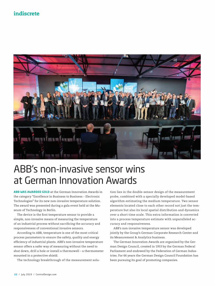
ABB WAS AWARDED GOLD at the German Innovation Awards in
the category “Excellence in Business to Business – Electronic
Technologies” for its new non-invasive temperature solution.
The award was presented during a gala event held at the Mu-
seum of Technology in Berlin.
The device is the �rst temperature sensor to provide a
simple, non-invasive means of measuring the temperature
of an industrial process without sacri�cing the accuracy and
responsiveness of conventional invasive sensors.
According to ABB, temperature is one of the most critical
process parameters to ensure the safety, quality and energy
ef�ciency of industrial plants. ABB’s non-invasive temperature
sensor offers a safer way of measuring without the need to
shut down, drill a hole or install a thermowell – a thermometer
mounted in a protective shield.
The technology breakthrough of the measurement solu-
tion lies in the double-sensor design of the measurement
probe, combined with a specially developed model-based
algorithm estimating the medium temperature. Two sensor
elements located close to each other record not just the tem-
perature but also its local spatial distribution and dynamics
over a short time scale. This extra information is converted
into a process temperature estimate with unparalleled ac-
curacy and responsiveness.
ABB’s non-invasive temperature sensor was developed
jointly by the Group’s German Corporate Research Center and
its Measurement & Analytics business.
The German Innovation Awards are organized by the Ger-
man Design Council, created in 1953 by the German Federal
Parliament and endowed by the Federation of German Indus-
tries. For 66 years the German Design Council Foundation has
been pursuing its goal of promoting companies.
indiscrete
ABB’s non-invasive sensor wins at German Innovation Awards
CD1907_15_25_Indiscrete.indd 22 7/9/19 3:30 PM

Ford honors Siemens at 21st Annual World Excellence AwardsSIEMENS WAS RECOGNIZED as a top-performing global
supplier at the 21st annual Ford World Excellence
Awards. Siemens was presented with a Gold Award by
Hau Thai-Tang, Ford chief product development and
purchasing of� cer and Linda Cash, Ford vice president,
quality and new model programs.
“Siemens is honored to receive this prestigious
award from Ford,” said Reinhold Niesing, head of verti-
cal markets automotive, Siemens Digital Industries US.
“Automation suppliers are not often recognized in this
category so this demonstrates that Siemens is mak-
ing the right strides in innovation and digitalization
Polyester
Die-cast Aluminum
StainlessSteel
IndustrialWall-mount
Polycarbonate
CD1907_15_25_Indiscrete.indd 23 7/9/19 3:30 PM
24 / July 2019 / ControlDesign.com
delivering improved quality, increased ef�ciency and shorter
time to market.”
Honorees were recognized for achievement in 10 categories,
including:
• Quality, sustainability, safe and smart categories for suppliers
that demonstrate leadership in Ford’s primary brand pillars
• Aligned business framework for suppliers that most exempli-
fy the framework’s principles, with an emphasis on quality,
value and innovation
• Special recognition for suppliers that delivered results ex-
ceeding expectations
• Diverse supplier of the year and supplier diversity develop-
ment corporation of the year to honor suppliers that excel
in integrating diversity into their organization and business
process
• Gold and silver for supplier manufacturing sites demonstrat-
ing superior quality, delivery and cost performance through-
out the year.
indiscrete
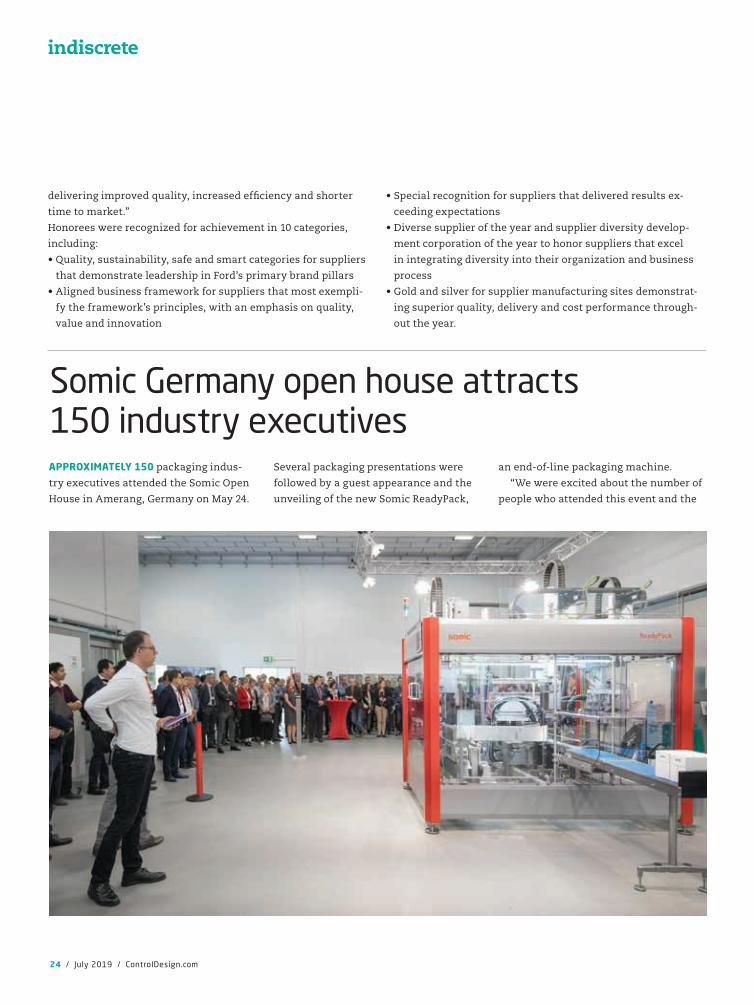
Somic Germany open house attracts 150 industry executivesAPPROXIMATELY 150 packaging indus-
try executives attended the Somic Open
House in Amerang, Germany on May 24.
Several packaging presentations were
followed by a guest appearance and the
unveiling of the new Somic ReadyPack,
an end-of-line packaging machine.
“We were excited about the number of
people who attended this event and the
CD1907_15_25_Indiscrete.indd 24 7/9/19 3:30 PM
ControlDesign.com / July 2019 / 25
introduction of the Somic ReadyPack,”
said Somic CEO Patrick Bonetsmüller.
“Our research indicates there is a market
for more simple packaging applications.
The challenge was to produce a machine
to �t industry requirements and meet
speci�c criteria such as speed, ef�ciency
and price points.”
“Seven months ago, we introduced the
Somic FLEXX III at PACK Expo in Chicago
as a �exible solution for one-piece wrap-
around shipping cases, or two-piece tray
and hood for retail ready,” said Peter Fox,
senior vice president of sales for Somic
America. “It is extremely fast at placing
stand-up pouches, �ow packs, rigid con-
tainers, and other units and has generated
a lot of interest. As a customized solution
for shelf-ready packages, we anticipate the
Somic ReadyPack to do the same.”
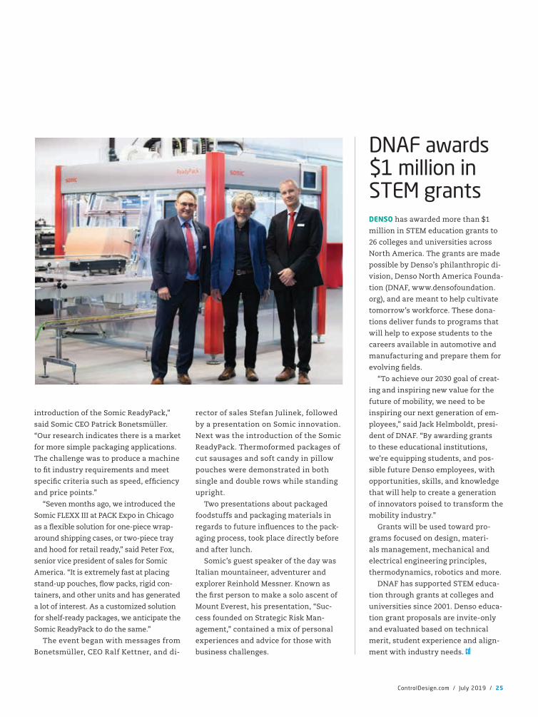
The event began with messages from
Bonetsmüller, CEO Ralf Kettner, and di-
rector of sales Stefan Julinek, followed
by a presentation on Somic innovation.
Next was the introduction of the Somic
ReadyPack. Thermoformed packages of
cut sausages and soft candy in pillow
pouches were demonstrated in both
single and double rows while standing
upright.
Two presentations about packaged
foodstuffs and packaging materials in
regards to future in�uences to the pack-
aging process, took place directly before
and after lunch.
Somic’s guest speaker of the day was
Italian mountaineer, adventurer and
explorer Reinhold Messner. Known as
the �rst person to make a solo ascent of
Mount Everest, his presentation, “Suc-
cess founded on Strategic Risk Man-
agement,” contained a mix of personal
experiences and advice for those with
business challenges.
DNAF awards $1 million in STEM grantsDENSO has awarded more than $1
million in STEM education grants to
26 colleges and universities across
North America. The grants are made
possible by Denso’s philanthropic di-
vision, Denso North America Founda-
tion (DNAF, www.densofoundation.
org), and are meant to help cultivate
tomorrow’s workforce. These dona-
tions deliver funds to programs that
will help to expose students to the
careers available in automotive and
manufacturing and prepare them for
evolving �elds.
“To achieve our 2030 goal of creat-
ing and inspiring new value for the
future of mobility, we need to be
inspiring our next generation of em-
ployees,” said Jack Helmboldt, presi-
dent of DNAF. “By awarding grants
to these educational institutions,
we’re equipping students, and pos-
sible future Denso employees, with
opportunities, skills, and knowledge
that will help to create a generation
of innovators poised to transform the
mobility industry.”
Grants will be used toward pro-
grams focused on design, materi-
als management, mechanical and
electrical engineering principles,
thermodynamics, robotics and more.
DNAF has supported STEM educa-
tion through grants at colleges and
universities since 2001. Denso educa-
tion grant proposals are invite-only
and evaluated based on technical
merit, student experience and align-
ment with industry needs.
CD1907_15_25_Indiscrete.indd 25 7/9/19 3:30 PM
WHAT DO MACHINE builders, system integrators and manufac-
turers need to know about time-sensitive networking (TSN)? In
simplest terms, it is better Ethernet.
What used to be many networks and gateways to meet
performance requirements will be deterministic control and
information on a single cable.
In addition to better performance, it will be easy to use, but the
integrators and end users are happy to support current solutions.
“I don’t think TSN will be complicating things for integrators
involved with advanced manufacturing and robotics,” says Bri-
an D McMorris, president at Futura Automation (www.futura-
automation.com) in Scottsdale, Arizona. “We are a factory-� oor
integrator. We do not know much about the IT world, but our
company structure and vision is focused on Industry 4.0, much
of which is executed on the factory � oor. For example, we are in
the manufacturing-execution-system (MES) world at an appli-
cation level with the Tulip product line of interfaces. We are the
� eld-services capability and help customers to implement the
bene� ts of an MES and a computerized maintenance manage-
ment system (CMMS) and a quality management system (QMS).”
Time-sensitive networks have many parts under development with some starting to emerge as real products, but the industrial specifi cations will need a few years to mature
by Dave Perkon, technical editor
26 / July 2019 / ControlDesign.com
cover story
CD1907_26_31_CoverStory.indd 26 7/9/19 4:49 PM
ControlDesign.com / July 2019 / 27
Futura works with IT mostly on the
security side, in terms of its cloud-based
solution and how the cloud apps are se-
cured. “I am sure it will be good to have
IEEE take a company-sponsored protocol
such as EtherCAT and turn it into a
global open standard under the auspices
of an industry association, but I do not
really see any shortcomings of EtherCAT
today, other than the license cost per
device for its use,” says McMorris.
While McMorris supports develop-
ments in networking technology, with
EtherCAT he has not see many limita-
tions. “We use EtherCAT with our Ser-
votronix drives for multi-axis control on
our open-design robots—cartesian and
delta,” he says. “It’s a very fast propri-
etary network with latency substan-
tially less than 1 microsecond, but it’s
only suitable for certain hard and soft
real-time computing requirements in
automation technology.”
Doug Putnam-Pite, director of soft-
ware development at Owens Design
(www.owensdesign.com) in Fremont,
California, appreciates that proprietary
networks such as EtherCAT and CC-Link
IE provide real-time communications, but
he also acknowledges their limitations.
“The downside to these technologies
is they only work with control devices
that support the protocol,” says Putnam-
Pite. “This means that you cannot have
devices on the same network that do not
support the protocol. These �eldbus net-
works must be separated from any other
Ethernet networks in the tool.”
TSN may allow devices that cannot
currently communicate in real time to
do so. “Time-sensitive networking gives
integrators more options on how to
architect control systems,” says Putnam-
Pite. “A tool with a time-sensitive net-
work may be able to decentralize control,
allowing individual devices to commu-
nicate directly with each other in real
time, allowing some level of control to be
of�oaded from a central tool controller.
Additionally, PCs may be able to com-
municate with time-sensitive network
devices in a semi-real-time manner.”
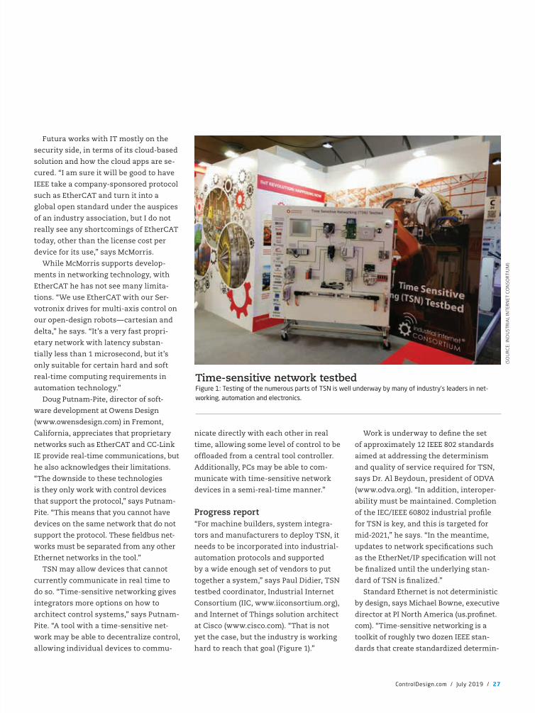
Progress report“For machine builders, system integra-
tors and manufacturers to deploy TSN, it
needs to be incorporated into industrial-
automation protocols and supported
by a wide enough set of vendors to put
together a system,” says Paul Didier, TSN
testbed coordinator, Industrial Internet
Consortium (IIC, www.iiconsortium.org),
and Internet of Things solution architect
at Cisco (www.cisco.com). “That is not
yet the case, but the industry is working
hard to reach that goal (Figure 1).”
Work is underway to de�ne the set
of approximately 12 IEEE 802 standards
aimed at addressing the determinism
and quality of service required for TSN,
says Dr. Al Beydoun, president of ODVA
(www.odva.org). “In addition, interoper-
ability must be maintained. Completion
of the IEC/IEEE 60802 industrial pro�le
for TSN is key, and this is targeted for
mid-2021,” he says. “In the meantime,
updates to network speci�cations such
as the EtherNet/IP speci�cation will not
be �nalized until the underlying stan-
dard of TSN is �nalized.”
Standard Ethernet is not deterministic
by design, says Michael Bowne, executive
director at PI North America (us.pro�net.
com). “Time-sensitive networking is a
toolkit of roughly two dozen IEEE stan-
dards that create standardized determin-
Time-sensitive network testbed Figure 1: Testing of the numerous parts of TSN is well underway by many of industry’s leaders in net-working, automation and electronics.
(SO
URC
E: IN
DU
STR
IAL
INTE
RN
ET C
ON
SORT
IUM
)
CD1907_26_31_CoverStory.indd 27 7/9/19 4:49 PM
istic Ethernet,” he explains. “Now that
other industries outside of industrial
automation are interested in determinis-
tic Ethernet, there is a larger market for
the hardware. The idea is that eventually
this technology will be available from
commercial off-the-shelf (COTS) chips.
Of the IEEE standards in the TSN toolbox,
we’ve identi�ed roughly half a dozen that
are particularly relevant to industrial
automation. These standards address
determinism with features like synchro-
nization, low latency, high availability,
and robustness.”
It’s important to get the standard
right, and that will take time. “As men-
tioned above, TSN is a toolbox of many
different standards, and not just one
thing,” says Bowne. “Some are relevant
to industrial automation, and some are
not. To ensure that we don’t end up with
different �avors of TSN in industrial
automation, an effort has been started
known as IEC/IEEE 60802. It is currently
staffed by engineers from automation
vendors big and small to ensure harmo-
nization across companies.”
The digital factory demands interop-
erability and simplicity in communica-
tions, says Armando Astarloa Cuéllar,
CEO, system-on-chip engineering, at
Relyum (www.relyum.com). “TSN is the
new-generation Ethernet designed ex-
pressly to meet those requirements,” he
says. Although the introduction of TSN
will be progressive depending on the
sector, some critical ones like railway,
automotive or aerospace, are adopting
TSN as the standard IT/OT network in
their new platforms.
Why should you care about TSN?“From the user’s perspective, at this time,
the status of time-sensitive network-
ing is at a bit of a standstill,” says Paul
Brooks, business development manager,
networks—IIPA, global standards, OPC
and time-sensitive networking, at Rock-
well Automation (www.rockwellautoma-
tion.com). “The TSN standards in IEEE
802 have been published, but they only
provide feature-level interoperability, not
system-level interoperability,” he says.
“Therefore, from the vendors’ perspec-
tive, we as the industrial automation
community are developing IEC/IEEE
60802, which will determine the indus-
trial automation pro�le for TSN to deliver
this system-level interoperability.”
Only when these standards are locked
down will protocol organizations, such as
28 / July 2019 / ControlDesign.com
cover story
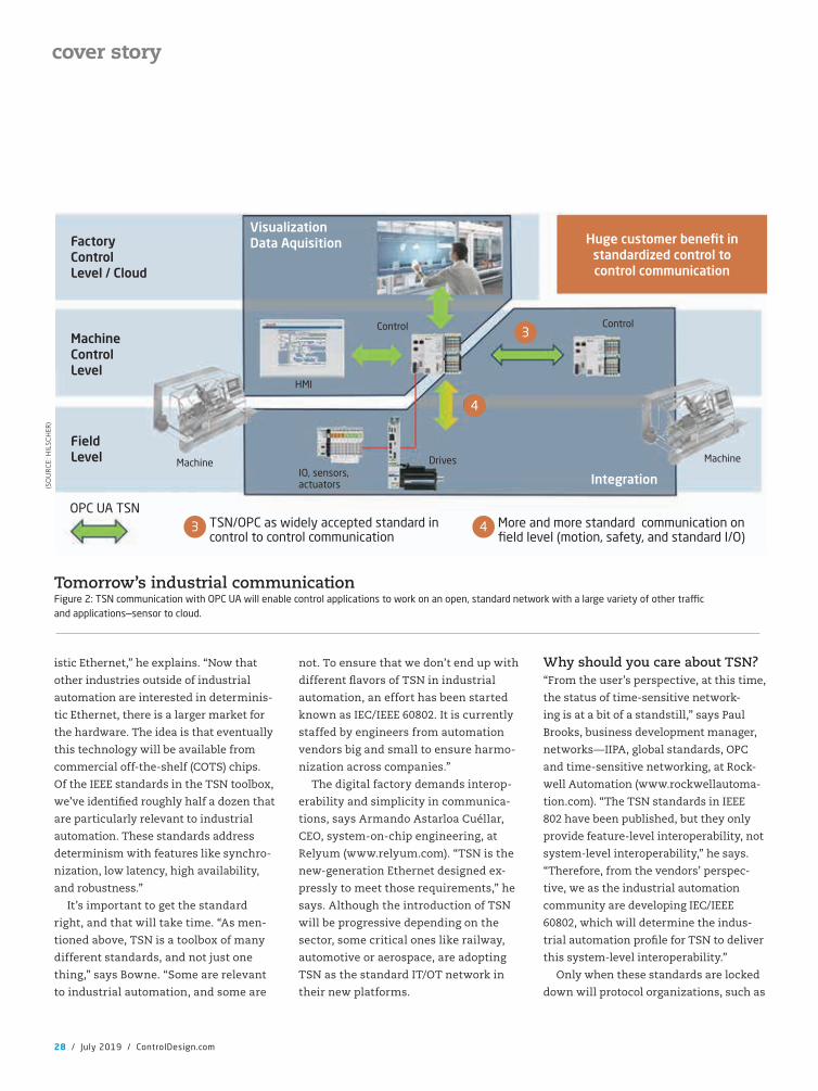
Tomorrow’s industrial communicationFigure 2: TSN communication with OPC UA will enable control applications to work on an open, standard network with a large variety of other tra�c and applications—sensor to cloud.
(SO
URC
E: H
ILSC
HER
)
FactoryControl Level / Cloud
MachineControlLevel
FieldLevel Machine
HMI
Control
VisualizationData Aquisition
Integration
Drives
Control
Machine
Huge customer benefit in standardized control to control communication
IO, sensors, actuators
OPC UA TSNTSN/OPC as widely accepted standard in control to control communication
3 More and more standard communication on field level (motion, safety, and standard I/O)
4
4
3
CD1907_26_31_CoverStory.indd 28 7/9/19 4:49 PM
ODVA, be able to publish that pro�le in speci�cations, continues
Brooks. “Some companies have been releasing pre-standard
products, and, while they will deliver user value, there is no
guarantee that these products will be compatible with the �nal
standard,” he said.
In November 2018, OPC Foundation announced the Field
Level Communication initiative supported by a very broad set
of industrial and IT players: ABB/B&R, Belden, Cisco, Huawei,
Intel, Mitsubishi, Moxa, Rockwell Automation, Schneider Elec-
tric, Siemens, among others, says Cisco’s Didier. “The vision is
to aim for an open, uni�ed, standards-based IIoT communica-
tion solution between sensors, actuators, controllers and cloud
addressing all requirements of industrial automation,” he says.
“The initiative will incorporate the OPC’s work on pub/sub and
TSN communication (Figure 2).”
TSN enables all the control applications to rely on an open,
standard network. “That network can also support a huge vari-
ety of other types of traf�c and applications. This convergence
and the ability to communicate, sensor to cloud are the key
improvements,” says Didier.
“TSN is designed to provide deterministic messaging and
real-time capability over standard Ethernet in order to ensure
communication of information in a �xed and predictable
amount of time,” explains Beydoun. “The key applications of
TSN will be those requiring precision timing control and deter-
ministic network behaviors. However, Ethernet TSN is desired
in any industrial application where higher bandwidth and
faster network response is desired as the case in network ap-
plications conveying audio and video information. TSN’s scal-
ability will allow high-bandwidth streaming of packets with a
guaranteed latency at higher Gigabit transfer rates.”
Why do I need TSN?“Many integrators and machine builders question the need
for TSN and claim the existing industrial Ethernet and related
protocols, such as EtherNet/IP, EtherCAT and Pro�net, meet
their needs, so ‘Why do I need TSN?’ is a common question,”
says Bowne at PI North America. “It’s a valid one, particularly
because many of the techniques employed by TSN—synchro-
nization, bandwidth reservation, scheduling—are ones we’ve
been using in Pro�net for more than 15 years. If TSN had ex-
isted back then, we would have adopted it and saved ourselves
lots of engineering effort. And yet Pro�net has always allowed
high-speed control-related traf�c to coexist plainly with other
information-related traf�c.”
The exact same principle applies to TSN, so, again, why do
you need it? “The answer is subtle and related to the future
of networking,” says Bowne. “As we move into the Industry
4.0/Industrial-Internet-of-Things (IIoT) realm, more and more
KEL-ER: Cable entry frames for routing preterminated cables with protection class up to IP66 / UL type 12/4X.
Certified protection class Very high strain relief according to EN 62444 Warranty of pre-terminated cables remains Quick assembly High cable density
www.icotek-usa.com
Split cable entry frame
Very high strain relief according to EN 62444
GET ONE 4 FREE!
312-643-2315
Wire Your Machine
With Pre-Terminated
Cables!UP TO
ULTYPE4X
Work is underway to de�ne the set of approximately 12 IEEE 802 standards aimed at addressing the determinism and quality of service required for TSN.
CD1907_26_31_CoverStory.indd 29 7/9/19 4:50 PM

information will be provided to higher-
level systems. Eventually, it appears that
some �attening of the Purdue Model may
occur. While TSN may not be the driver
of this, it certainly can be one of the
tools to help enable it.”
In the future we envision that as more
and more bandwidth gets utilized by
IT protocols, TSN will ensure time-
sensitive—hence, the name—OT traf�c
receives the determinism it requires,
even on networks loaded with other
best-effort IT traf�c, explains Bowne.
“As long as they all share a common TSN
foundation, then manufacturers can
begin implementing converged IT/OT
networks without having to worry about
their OT traf�c being sacri�ced at the
expense of IT traf�c,” he says. “We want
to continue this long-held philosophy
because we believe in using the right
tool for the right task: the Pro�net proto-
col for moving data, other protocols, for
example, OPC UA, for moving informa-
tion, all on a single wire.”
The OT/IT integration roadmap does
not end in an intermediate situation
with a plethora of heterogenous devices
connected through gateways, says
Cuéllar at Relyum. “Instead, it raises the
adoption of a communication technol-
ogy at the link level that is valid for
both worlds,” he says. “In this way, it
would be feasible for an all-to-all data
exchange topology in a homogeneous
plant, similar to a pillar (Figure 3).”
This automation pillar is based on a
blog post titled, “What is TSN? A Look at
Its Role in Future Ethernet Networks,”
(www.controldesign.com/whatistsn) by
René Hummen, senior architect—tech-
nology and innovation, at Belden (www.
belden.com).
In this pillar context, the traditional
layer-based communication and cyber-
security scheme in no longer valid. “The
elements included in the �eld I/O would
communicate directly with applications
and services enabled in remote cloud,”
explains Cuéllar. “Thus, it is critical to
secure communication between the
different devices. The real-time require-
ments of TSN represent one of the great
challenges for securing this kind of
network because traditional cyberse-
curity IT mechanisms can’t guarantee
the transmission of packets with the
required latency.”
TSN is not a protocolTSN is just another better version of
Ethernet; it’s not a protocol. “What’s im-
proving is the infrastructure upon which
all Ethernet-based protocols exist,”
30 / July 2019 / ControlDesign.com
cover story
The data link near the physical layerFigure 4: TSN resides in the Data Link Layer 2 of the IOS/OSI Model and is not a protocol, which resides in Application Layer 7.
(SO
URC
E: P
I NO
RTH
AM
ERIC
A)
5-7 Session / Presentation / Application 5-7 Session / Presentation / Application
UDP TCP4 Transport layer
IP3 Network layer
RT IRT2 Data Link layer TSN
100 Mbit / 1 GBit / ...1 Physical layer
Automation pillarFigure 3: The automation pillar shows clear, high-speed connections between the plant floor I/O devices and controllers to the factory, enterprise level and to the cloud.
(SO
URC
E: B
ELD
EN V
IA S
YST
EM-O
N-C
HIP
EN
GIN
EER
ING
)
ERPBI
MES SCADA
CONTROL PLC
FIELD IO
Increased interactionCentralized supervision
Control functions Virtual PCDistributed control
Increase of device numbers
Conn
ecti
vity
Field / IO
Cyber-physical production system’s distributed control unit merges PLC & I/O modules
On-pemises automation cloud
Dat
a up
load
Uplink to global cloud
ML /IA
Factory backbone
TSN
: Hig
h-ba
ndw
idth
- re
al t
ime
capa
ble
ML / IA Microservices
Virtual PLC
Cloud connection
Secure remote access
CD1907_26_31_CoverStory.indd 30 7/9/19 4:50 PM
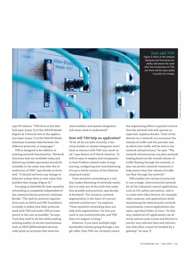
says PI’s Bowne. “TSN lives at the data
link layer (Layer 2) of the IOS/OSI Model
(Figure 4). Protocols live at the applica-
tion layer (Layer 7) of the ISO/OSI Model.
Gateways translate data between the
different protocols, or languages.”
TSN is designed to be additive to
existing network functionality. “Network
functions that are available today and
delivering reliable operations should be
available in the same way after the in-
troduction of TSN,” says Brooks at Rock-
well. “It should not force any change in
behavior unless there is new value that
justi�es that change (Figure 5).”
Focusing on EtherNet/IP, time-sensitive
networking is completely independent of
the communications protocol, continues
Brooks. “The task for protocol organiza-
tions such as ODVA and OPC Foundation
is simply to de�ne how their protocols
work with TSN and make TSN as trans-
parent to the user as possible,” he says.
“And they need to do this while making
existing quality-of-service mechanisms
such as DSCP (differentiated services
code point) an acronym that most ma-
chine builders and system integrators
will never need to understand!”
How will TSN help an application?“If we all do our jobs correctly, a ma-
chine builder or system integrator won’t
have to interact with TSN very much at
all,” says Bowne at PI North America. “It
will be easy to employ and transparent
to their Pro�net-related tasks of engi-
neering, con�guring and commissioning.
It’s just a better version of the Ethernet
employed today.”
Time-sensitive networking is a tool
that makes �attening of networks easier,
but it is only one of the tools that make
this possible and practical, says Brooks
at Rockwell. “For instance, network
segmentation is the heart of a secure
network architecture,” he explains.
“Time-sensitive networking does not
help with segmentation. For this you
need to use routed protocols, and TSN
does not support routing.”
However, if you have multiple high-
bandwidth streams going through a sin-
gle cable, then TSN can certainly reduce
the engineering efforts required to know
that the network link will operate as
expected, explains Brooks. “Each of the
devices on a network can announce the
volume of traf�c and the periodic rate
at which that traf�c will be sent to the
network infrastructure,” he says. “The
network infrastructure can plan network
loading based on the overall volume of
traf�c �owing through the network. It
also can protect network resources to
help ensure that this volume of traf�c
can �ow through the network.”
TSN enables the various IE protocols
to use a single, interconnected network
for all the industrial control applications,
such as I/O, safety and motion, and to
co-exist with other devices, for example,
video cameras, and applications while
maintaining the deterministic network
requirements control applications rely
upon, says Paul Didier at Cisco. “In this
way, Industrial IoT applications can di-
rectly and securely access end devices to
extract very relevant data and informa-
tion that often cannot be handled by a
gateway,” he says.
ControlDesign.com / July 2019 / 31
(SO
URC
E: R
OC
KW
ELL
AU
TOM
ATI
ON
)
Just add TSNFigure 5: Much of the network
hardware and functional reli-ability will remain the same
after the introduction of TSN, but there will be value added
to justify the change.
CD1907_26_31_CoverStory.indd 31 7/9/19 4:50 PM
MAN OVERBOARD! THERE are times
when rescue boats must be placed over
the deck and into the water to assist
those in distress. However, launching
a boat from a larger vessel is not easy,
and the captain may need to make these
launches and recoveries day or night—
with little or no light. And it will need
to be done in the open ocean, and that’s
not often �at and calm.
To further complicate things, the
rescue boat may be launched while
underway—the boat doesn’t stop. Allied
Systems (www.alliedsystems.com), a
fabricator of material handling equip-
ment, was contacted for these and other
reasons. The marine industry desired
a safer launch and retrieval system for
rescue boats—particularly in adverse
weather conditions. Safer operation was
paramount (Figure 1).
Get the boat in or out of the water safelyMany vessels use a single davit to launch
a boat. A davit system is basically a crane
that’s used to lower and lift boats—rela-
tively small boats—from the deck to the
water and back. Examples include davits
along a line of life boats that would be on
an ocean liner and other large vessels.
The problem is if a 30-ft-long boat is
lowered with one davit during a storm,
the stability of that boat being lifted or
lowered by one cable is very limited. Pic-
ture a severe, windy storm with signi�-
cant wave action and then trying to lift a
life or rescue boat off a large ship—with
people on it—and then into the water. In-
variably, the rescue boat will pitch about
due to the motion of the parent ship from
which it was launched, due to wind veloc-
ity and sea state. Wind velocity could
easily propel the boat back and forth in an
uncontrolled manner. This is dangerous
for the crew and passengers that may be
onboard, and impacting the side of the
parent ship could damage either vessel.
A dual-point davit system uses two
cables—one attaches to the stern of the
boat, the other the bow. This system
reduces the unwanted rescue boat mo-
tion. The dual davit lowers the boat very
uniformly, which is much more stable
and safe for the people in it, even when
launched in a rough sea.
The solutionIn the marine industry, many of the davit
systems for shipboard use are manually
operated using a single hand-driven or
electric winch and a single cable. The
Allied Systems’ dual-point davit is au-
tomated, and it partnered with Systems
Interface to design, manufacturer and
test it. The operator console also provides
more feedback on loading, positions,
maintenance and troubleshooting.
Allied Systems, located in Sherwood,
Oregon, has sold more than a half dozen
of these specially designed dual-point
davit systems. These systems have a
nominal working load limit of 11,000
lb and can handle boats up to 30 ft in
length. They are also designed to operate
any time, day or night, from the North
Pole to the equator, from �at water to Sea
State 5, which is a rough sea with about
8-ft to more than 13-ft waves.
The Rockwell Automation control
system solution was used to control
the automatic operation of the system.
The controller synchronized the two
winch systems, and the operator station
increased safety of both personnel and
equipment.
Becoming shipmatesThe new dual-point davit system was the
�rst time Allied Systems worked with
Systems Interface (www.systems-inter-
face.com), a control system integrator and
Rockwell Automation solution partner.
The scope of work was basically divided
with Allied taking on the mechanical and
hydraulic design and related manufactur-
ing aspects while Systems Interface took
on the electrical design, control panel
build and programming aspects.
Allied Systems began designing and
manufacturing equipment for the wood
product industry more than 40 years ago.
Its success allowed the company to diver-
sify into the marine, coal and agriculture
industries. In the marine market, it serves
a wide host of customers from family-
owned companies to worldwide corpora-
tions and different government agencies.
Systems Interface has worked with
Rockwell Automation for more than three
decades. One of its fortes is the marine
by Tim Rogers, Systems Interface
How to get a boat in the waterWith the proper tension, the dual-point davit system, mounted to large vessels,
can get boats into and out of rough water without making waves
32 / July 2019 / ControlDesign.com
controllers
CD1907_32_35_CaseStudy_featr.indd 32 7/9/19 3:32 PM
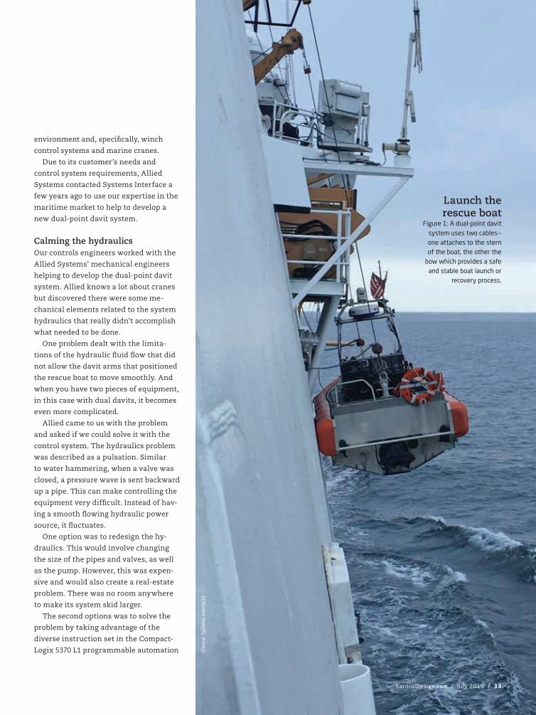
ControlDesign.com / July 2019 / 33
(Sou
rce:
Sys
tem
s In
terf
ace)
Launch the rescue boat
Figure 1: A dual-point davit system uses two cables—one attaches to the stern of the boat, the other the
bow which provides a safe and stable boat launch or
recovery process.
environment and, speci�cally, winch
control systems and marine cranes.
Due to its customer’s needs and
control system requirements, Allied
Systems contacted Systems Interface a
few years ago to use our expertise in the
maritime market to help to develop a
new dual-point davit system.
Calming the hydraulicsOur controls engineers worked with the
Allied Systems’ mechanical engineers
helping to develop the dual-point davit
system. Allied knows a lot about cranes
but discovered there were some me-
chanical elements related to the system
hydraulics that really didn’t accomplish
what needed to be done.
One problem dealt with the limita-
tions of the hydraulic �uid �ow that did
not allow the davit arms that positioned
the rescue boat to move smoothly. And
when you have two pieces of equipment,
in this case with dual davits, it becomes
even more complicated.
Allied came to us with the problem
and asked if we could solve it with the
control system. The hydraulics problem
was described as a pulsation. Similar
to water hammering, when a valve was
closed, a pressure wave is sent backward
up a pipe. This can make controlling the
equipment very dif�cult. Instead of hav-
ing a smooth �owing hydraulic power
source, it �uctuates.
One option was to redesign the hy-
draulics. This would involve changing
the size of the pipes and valves, as well
as the pump. However, this was expen-
sive and would also create a real-estate
problem. There was no room anywhere
to make its system skid larger.
The second options was to solve the
problem by taking advantage of the
diverse instruction set in the Compact-
Logix 5370 L1 programmable automation
CD1907_32_35_CaseStudy_featr.indd 33 7/9/19 3:32 PM
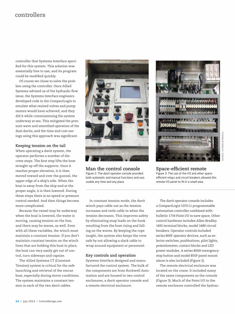
controller that Systems Interface speci-
�ed for this system. This solution was
essentially free to use, and its program
could be modi�ed quickly.
Of course we chose to solve the prob-
lem using the controller. Once Allied
Systems advised us of the hydraulic �ow
issue, the Systems Interface engineers
developed code in the CompactLogix to
emulate what resized valves and pump
motors would have achieved, and they
did it while commissioning the system
underway at sea. This mitigated the pres-
sure wave and smoothed operation of the
dual davits, and the time and cost sav-
ings using this approach was signi�cant.
Keeping tension on the tailWhen operating a davit system, the
operator performs a number of dis-
crete steps. The �rst step lifts the boat
straight up off the supports. Once it
reaches proper elevation, it is then
moved toward and over the gunnel, the
upper edge of a ship’s side. When the
boat is away from the ship and at the
proper angle, it is then lowered. During
these steps there is no speed or pressure
control needed. And then things become
more complicated.
Because the vessel may be underway
when the boat is lowered, the water is
moving, causing tension on the line,
and there may be waves, as well. Even
with all these variables, the winch must
maintain a constant tension. If you don’t
maintain constant tension on the winch
lines that are holding this boat in place,
the boat can very easily get out of con-
trol, turn sideways and capsize.
The Allied Systems CT (Constant
Tension) system is critical for the safe
launching and retrieval of the rescue
boat, especially during storm conditions.
The system maintains a constant ten-
sion in each of the two davit cables.
In constant tension mode, the davit
winch pays cable out as the tension
increases and reels cable in when the
tension decreases. This improves safety
by eliminating snap loads on the hook
resulting from the boat rising and fall-
ing on the waves. By keeping the rope
taught, the system also keeps the crew
safe by not allowing a slack cable to
wrap around equipment or personnel.
Key controls and operationSystems Interface designed and manu-
factured the control system. The bulk of
the components are from Rockwell Auto-
mation and are housed in two control
enclosures, a davit operator console and
a remote electrical enclosure.
The davit operator console includes
a CompactLogix 5370 L1 programmable
automation controller combined with
bulletin 1734 Point I/O to save space. Other
control hardware includes Allen-Bradley
1492 terminal blocks, model 1489 circuit
breakers. Operator controls included
series 800F operator devices, such as se-
lector switches, pushbuttons, pilot lights,
potentiometer, contact blocks and LED
power modules. A series 800H emergency-
stop button and model 855P panel mount
alarm is also included (Figure 2).
The remote electrical enclosure was
located on the crane. It included many
of the same components as the console
(Figure 3). Much of the Point I/O in the
remote enclosure controlled the hydrau-
34 / July 2019 / ControlDesign.com
controllers
Space-ef�cient remoteFigure 3: The use of the I/O and other space-e�cient relays and circuit breakers allowed this remote I/O panel to fit in a small area.
(SO
URC
E: S
YST
EMS
INTE
RFA
CE)
Man the control consoleFigure 2: The davit operator console provided both automatic and manual functions and was usable any time and any place.
CD1907_32_35_CaseStudy_featr.indd 34 7/9/19 3:32 PM
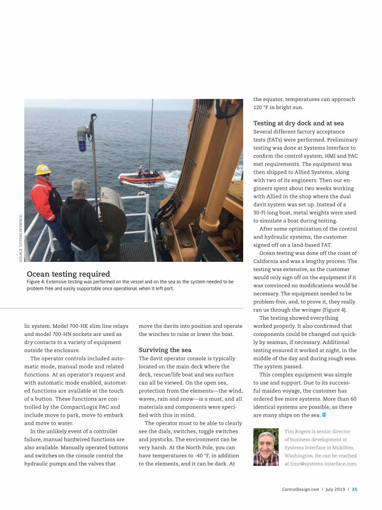
lic system. Model 700-HK slim line relays
and model 700-HN sockets are used as
dry contacts to a variety of equipment
outside the enclosure.
The operator controls included auto-
matic mode, manual mode and related
functions. At an operator’s request and
with automatic mode enabled, automat-
ed functions are available at the touch
of a button. These functions are con-
trolled by the CompactLogix PAC and
include move to park, move to embark
and move to water.
In the unlikely event of a controller
failure, manual hardwired functions are
also available. Manually operated buttons
and switches on the console control the
hydraulic pumps and the valves that
move the davits into position and operate
the winches to raise or lower the boat.
Surviving the seaThe davit operator console is typically
located on the main deck where the
deck, rescue/life boat and sea surface
can all be viewed. On the open sea,
protection from the elements—the wind,
waves, rain and snow—is a must, and all
materials and components were speci-
�ed with this in mind.
The operator must to be able to clearly
see the dials, switches, toggle switches
and joysticks. The environment can be
very harsh. At the North Pole, you can
have temperatures to -40 °F, in addition
to the elements, and it can be dark. At
the equator, temperatures can approach
120 °F in bright sun.
Testing at dry dock and at seaSeveral different factory acceptance
tests (FATs) were performed. Preliminary
testing was done at Systems Interface to
con�rm the control system, HMI and PAC
met requirements. The equipment was
then shipped to Allied Systems, along
with two of its engineers. Then our en-
gineers spent about two weeks working
with Allied in the shop where the dual
davit system was set up. Instead of a
30-ft-long boat, metal weights were used
to simulate a boat during testing.
After some optimization of the control
and hydraulic systems, the customer
signed off on a land-based FAT.
Ocean testing was done off the coast of
California and was a lengthy process. The
testing was extensive, as the customer
would only sign off on the equipment if it
was convinced no modi�cations would be
necessary. The equipment needed to be
problem-free, and, to prove it, they really
ran us through the wringer (Figure 4).
The testing showed everything
worked properly. It also con�rmed that
components could be changed out quick-
ly by seaman, if necessary. Additional
testing ensured it worked at night, in the
middle of the day and during rough seas.
The system passed.
This complex equipment was simple
to use and support. Due to its success-
ful maiden voyage, the customer has
ordered �ve more systems. More than 60
identical systems are possible, as there
are many ships on the sea.
Tim Rogers is senior director
of business development at
Systems Interface in Mukilteo,
Washington. He can be reached
ControlDesign.com / July 2019 / 35
(SO
URC
E: S
YST
EMS
INTE
RFA
CE)
Ocean testing requiredFigure 4: Extensive testing was performed on the vessel and on the sea as the system needed to be problem-free and easily supportable once operational, when it left port.
CD1907_32_35_CaseStudy_featr.indd 35 7/9/19 3:32 PM
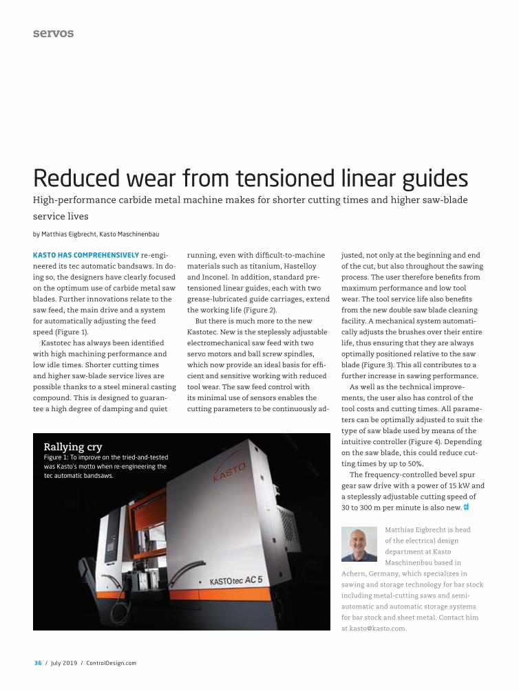
KASTO HAS COMPREHENSIVELY re-engi-
neered its tec automatic bandsaws. In do-
ing so, the designers have clearly focused
on the optimum use of carbide metal saw
blades. Further innovations relate to the
saw feed, the main drive and a system
for automatically adjusting the feed
speed (Figure 1).
Kastotec has always been identi�ed
with high machining performance and
low idle times. Shorter cutting times
and higher saw-blade service lives are
possible thanks to a steel mineral casting
compound. This is designed to guaran-
tee a high degree of damping and quiet
running, even with dif�cult-to-machine
materials such as titanium, Hastelloy
and Inconel. In addition, standard pre-
tensioned linear guides, each with two
grease-lubricated guide carriages, extend
the working life (Figure 2).
But there is much more to the new
Kastotec. New is the steplessly adjustable
electromechanical saw feed with two
servo motors and ball screw spindles,
which now provide an ideal basis for ef�-
cient and sensitive working with reduced
tool wear. The saw feed control with
its minimal use of sensors enables the
cutting parameters to be continuously ad-
justed, not only at the beginning and end
of the cut, but also throughout the sawing
process. The user therefore bene�ts from
maximum performance and low tool
wear. The tool service life also bene�ts
from the new double saw blade cleaning
facility. A mechanical system automati-
cally adjusts the brushes over their entire
life, thus ensuring that they are always
optimally positioned relative to the saw
blade (Figure 3). This all contributes to a
further increase in sawing performance.
As well as the technical improve-
ments, the user also has control of the
tool costs and cutting times. All parame-
ters can be optimally adjusted to suit the
type of saw blade used by means of the
intuitive controller (Figure 4). Depending
on the saw blade, this could reduce cut-
ting times by up to 50%.
The frequency-controlled bevel spur
gear saw drive with a power of 15 kW and
a steplessly adjustable cutting speed of
30 to 300 m per minute is also new.
Matthias Eigbrecht is head
of the electrical design
department at Kasto
Maschinenbau based in
Achern, Germany, which specializes in
sawing and storage technology for bar stock
including metal-cutting saws and semi-
automatic and automatic storage systems
for bar stock and sheet metal. Contact him
by Matthias Eigbrecht, Kasto Maschinenbau
Reduced wear from tensioned linear guidesHigh-performance carbide metal machine makes for shorter cutting times and higher saw-blade
service lives
36 / July 2019 / ControlDesign.com
servos
Rallying cryFigure 1: To improve on the tried-and-tested was Kasto’s motto when re-engineering the tec automatic bandsaws.
CD1907_36_37_Featr1_featr.indd 36 7/9/19 3:34 PM
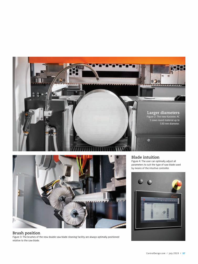
ControlDesign.com / July 2019 / 37
Brush positionFigure 3: The brushes of the new double saw blade cleaning facility are always optimally positioned relative to the saw blade.
Blade intuitionFigure 4: The user can optimally adjust all parameters to suit the type of saw blade used by means of the intuitive controller.
Larger diametersFigure 2: The new Kastotec AC
5 saws round material up to 530 mm diameter.
CD1907_36_37_Featr1_featr.indd 37 7/9/19 3:34 PM

THE LANGUAGE USED by suppliers of technology solutions
aimed at precision engineering applications is vague and in
some instances confusing. Words such as “precision” and
“resolution” without any degree of quali�cation are just
meaningless. When looking at motion-control solutions that
provide sub-micron and nanometer-level accuracy, a new
language is necessary, and new standards are required to
indicate the real levels of precision that different motion-
control solutions can achieve.
There are times when technological advancements are such
that they necessitate a root and branch change in the language
and nature of discussion associated with them.
When electricity became available in every
home, it would have been somewhat perverse
if we had all continued to talk in terms of our
preferred candles rather than the relative lumi-
nescence and longevity of various forms of light
bulbs. Likewise, when the car began to emerge,
and eventually replaced the horse and cart as
the most ef�cient form of transportation, the
discussion logically switched from the best hay
to feed the horse to the merits of different forms
of internal combustion.
Without stretching this analogy to the break-
ing point, there is a similar shift in the area of
motion control. A new technology has emerged
that pushes the boundaries of what is deemed possible in
terms of precision to such an extent that the language
surrounding the technology has to change, and the
nature of the conversation needs to shift in order
to differentiate this new technology from standard
industry alternatives.
The technology in question is our Hybrid
Hexapod (Figure 1). We are in blue-ocean territory
here. In the past 20-25 years, there has been more
and more interest in hexapods to cater for the increased de-
mand for micron, and sub-micron level precision in multi-axis
motion applications. Hexapod motion-control technology exists
at the ultra-precision end of motion control, and it has been the
best-in-class motion control solution for exacting industrial ap-
plications for a couple of decades.
The burgeoning area of more and more precise motion
control is driven by industry demand for technologies that
will improve production processes. The emphasis from across
industry is for smarter, smaller and faster precision motion
control and positioning equipment, and demand is especially
by Bill Hennessey, Alio Industries
What is the point of precision?How to clarify the meaning of precision for better understanding of motion
38 / July 2019 / ControlDesign.com
motion control
New stepsFigure 1: The Hybrid Hexapod represents a step forward in motion control and provides the ability to achieve repeatable nano-level accuracy, stimulating innovation and pro-moting manufacturing e�ciency.
CD1907_38_40_Featr2_featr.indd 38 7/9/19 3:36 PM
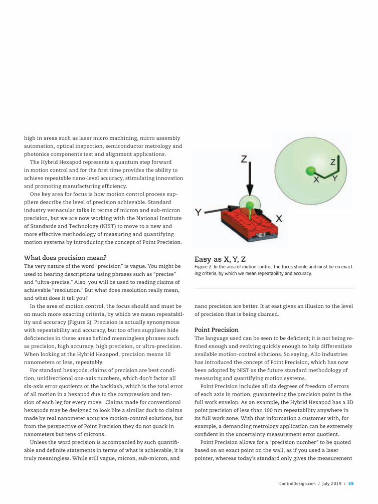
high in areas such as laser micro machining, micro assembly
automation, optical inspection, semiconductor metrology and
photonics components test and alignment applications.
The Hybrid Hexapod represents a quantum step forward
in motion control and for the �rst time provides the ability to
achieve repeatable nano-level accuracy, stimulating innovation
and promoting manufacturing ef�ciency.
One key area for focus is how motion control process sup-
pliers describe the level of precision achievable. Standard
industry vernacular talks in terms of micron and sub-micron
precision, but we are now working with the National Institute
of Standards and Technology (NIST) to move to a new and
more effective methodology of measuring and quantifying
motion systems by introducing the concept of Point Precision.
What does precision mean?The very nature of the word “precision” is vague. You might be
used to hearing descriptions using phrases such as “precise”
and “ultra-precise.” Also, you will be used to reading claims of
achievable “resolution.” But what does resolution really mean,
and what does it tell you?
In the area of motion control, the focus should and must be
on much more exacting criteria, by which we mean repeatabil-
ity and accuracy (Figure 2). Precision is actually synonymous
with repeatability and accuracy, but too often suppliers hide
de�ciencies in these areas behind meaningless phrases such
as precision, high accuracy, high precision, or ultra-precision.
When looking at the Hybrid Hexapod, precision means 10
nanometers or less, repeatably.
For standard hexapods, claims of precision are best condi-
tion, unidirectional one-axis numbers, which don’t factor all
six-axis error quotients or the backlash, which is the total error
of all motion in a hexapod due to the compression and ten-
sion of each leg for every move. Claims made for conventional
hexapods may be designed to look like a similar duck to claims
made by real nanometer accurate motion-control solutions, but
from the perspective of Point Precision they do not quack in
nanometers but tens of microns.
Unless the word precision is accompanied by such quanti�-
able and de�nite statements in terms of what is achievable, it is
truly meaningless. While still vague, micron, sub-micron, and
nano precision are better. It at east gives an illusion to the level
of precision that is being claimed.
Point PrecisionThe language used can be seen to be de�cient; it is not being re-
�ned enough and evolving quickly enough to help differentiate
available motion-control solutions. So saying, Alio Industries
has introduced the concept of Point Precision, which has now
been adopted by NIST as the future standard methodology of
measuring and quantifying motion systems.
Point Precision includes all six degrees of freedom of errors
of each axis in motion, guaranteeing the precision point in the
full work envelop. As an example, the Hybrid Hexapod has a 3D
point precision of less than 100 nm repeatability anywhere in
its full work zone. With that information a customer with, for
example, a demanding metrology application can be extremely
con�dent in the uncertainty measurement error quotient.
Point Precision allows for a “precision number” to be quoted
based on an exact point on the wall, as if you used a laser
pointer, whereas today’s standard only gives the measurement
ControlDesign.com / July 2019 / 39
Easy as X, Y, ZFigure 2: In the area of motion control, the focus should and must be on exact-ing criteria, by which we mean repeatability and accuracy.
CD1907_38_40_Featr2_featr.indd 39 7/9/19 3:36 PM
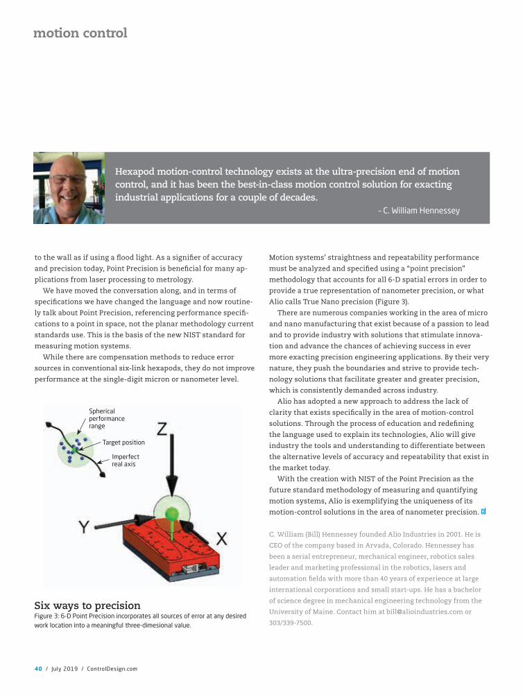
to the wall as if using a �ood light. As a signi�er of accuracy
and precision today, Point Precision is bene�cial for many ap-
plications from laser processing to metrology.
We have moved the conversation along, and in terms of
speci�cations we have changed the language and now routine-
ly talk about Point Precision, referencing performance speci�-
cations to a point in space, not the planar methodology current
standards use. This is the basis of the new NIST standard for
measuring motion systems.
While there are compensation methods to reduce error
sources in conventional six-link hexapods, they do not improve
performance at the single-digit micron or nanometer level.
Motion systems’ straightness and repeatability performance
must be analyzed and speci�ed using a “point precision”
methodology that accounts for all 6-D spatial errors in order to
provide a true representation of nanometer precision, or what
Alio calls True Nano precision (Figure 3).
There are numerous companies working in the area of micro
and nano manufacturing that exist because of a passion to lead
and to provide industry with solutions that stimulate innova-
tion and advance the chances of achieving success in ever
more exacting precision engineering applications. By their very
nature, they push the boundaries and strive to provide tech-
nology solutions that facilitate greater and greater precision,
which is consistently demanded across industry.
Alio has adopted a new approach to address the lack of
clarity that exists speci�cally in the area of motion-control
solutions. Through the process of education and rede�ning
the language used to explain its technologies, Alio will give
industry the tools and understanding to differentiate between
the alternative levels of accuracy and repeatability that exist in
the market today.
With the creation with NIST of the Point Precision as the
future standard methodology of measuring and quantifying
motion systems, Alio is exemplifying the uniqueness of its
motion-control solutions in the area of nanometer precision.
C. William (Bill) Hennessey founded Alio Industries in 2001. He is
CEO of the company based in Arvada, Colorado. Hennessey has
been a serial entrepreneur, mechanical engineer, robotics sales
leader and marketing professional in the robotics, lasers and
automation �elds with more than 40 years of experience at large
international corporations and small start-ups. He has a bachelor
of science degree in mechanical engineering technology from the
University of Maine. Contact him at [email protected] or
303/339-7500.
40 / July 2019 / ControlDesign.com
motion control
Spherical performance range
Target position
Imperfect real axis
Six ways to precisionFigure 3: 6-D Point Precision incorporates all sources of error at any desired work location into a meaningful three-dimesional value.
Hexapod motion-control technology exists at the ultra-precision end of motion control, and it has been the best-in-class motion control solution for exacting industrial applications for a couple of decades.
– C. William Hennessey
CD1907_38_40_Featr2_featr.indd 40 7/9/19 3:36 PM
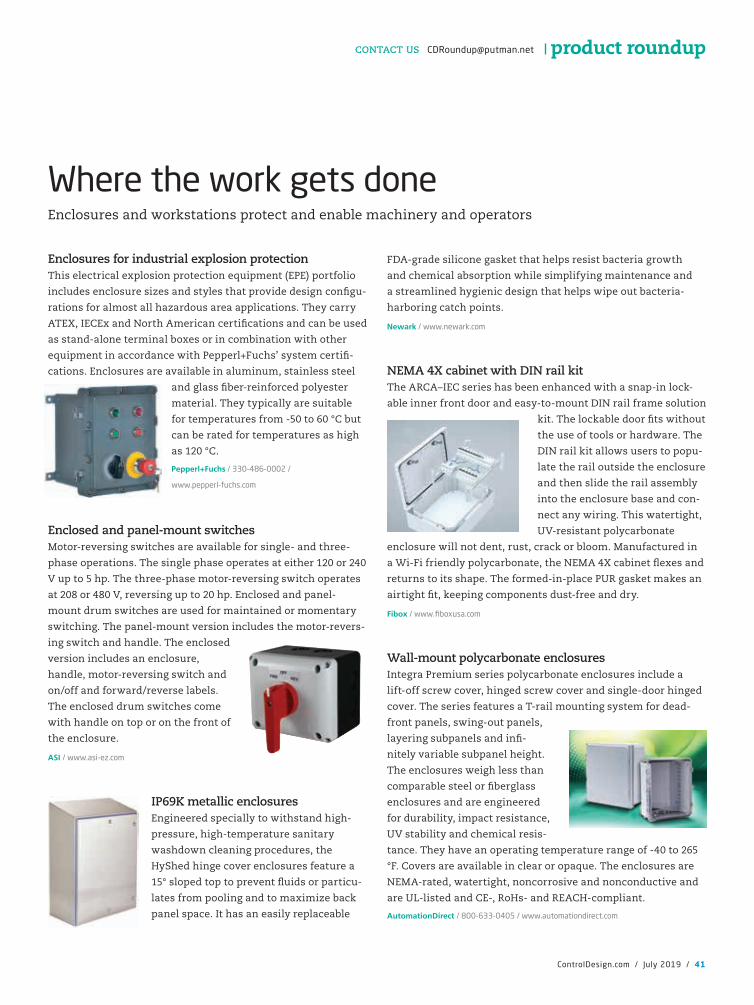
ControlDesign.com / July 2019 / 41
Enclosures for industrial explosion protection This electrical explosion protection equipment (EPE) portfolio
includes enclosure sizes and styles that provide design con�gu-
rations for almost all hazardous area applications. They carry
ATEX, IECEx and North American certi�cations and can be used
as stand-alone terminal boxes or in combination with other
equipment in accordance with Pepperl+Fuchs’ system certi�-
cations. Enclosures are available in aluminum, stainless steel
and glass �ber-reinforced polyester
material. They typically are suitable
for temperatures from -50 to 60 °C but
can be rated for temperatures as high
as 120 °C.
Pepperl+Fuchs / 330-486-0002 /
www.pepperl-fuchs.com
Enclosed and panel-mount switches Motor-reversing switches are available for single- and three-
phase operations. The single phase operates at either 120 or 240
V up to 5 hp. The three-phase motor-reversing switch operates
at 208 or 480 V, reversing up to 20 hp. Enclosed and panel-
mount drum switches are used for maintained or momentary
switching. The panel-mount version includes the motor-revers-
ing switch and handle. The enclosed
version includes an enclosure,
handle, motor-reversing switch and
on/off and forward/reverse labels.
The enclosed drum switches come
with handle on top or on the front of
the enclosure.
ASI / www.asi-ez.com
IP69K metallic enclosuresEngineered specially to withstand high-
pressure, high-temperature sanitary
washdown cleaning procedures, the
HyShed hinge cover enclosures feature a
15° sloped top to prevent �uids or particu-
lates from pooling and to maximize back
panel space. It has an easily replaceable
FDA-grade silicone gasket that helps resist bacteria growth
and chemical absorption while simplifying maintenance and
a streamlined hygienic design that helps wipe out bacteria-
harboring catch points.
Newark / www.newark.com
NEMA 4X cabinet with DIN rail kitThe ARCA–IEC series has been enhanced with a snap-in lock-
able inner front door and easy-to-mount DIN rail frame solution
kit. The lockable door �ts without
the use of tools or hardware. The
DIN rail kit allows users to popu-
late the rail outside the enclosure
and then slide the rail assembly
into the enclosure base and con-
nect any wiring. This watertight,
UV-resistant polycarbonate
enclosure will not dent, rust, crack or bloom. Manufactured in
a Wi-Fi friendly polycarbonate, the NEMA 4X cabinet �exes and
returns to its shape. The formed-in-place PUR gasket makes an
airtight �t, keeping components dust-free and dry.
Fibox / www.fiboxusa.com
Wall-mount polycarbonate enclosures Integra Premium series polycarbonate enclosures include a
lift-off screw cover, hinged screw cover and single-door hinged
cover. The series features a T-rail mounting system for dead-
front panels, swing-out panels,
layering subpanels and in�-
nitely variable subpanel height.
The enclosures weigh less than
comparable steel or �berglass
enclosures and are engineered
for durability, impact resistance,
UV stability and chemical resis-
tance. They have an operating temperature range of -40 to 265
°F. Covers are available in clear or opaque. The enclosures are
NEMA-rated, watertight, noncorrosive and nonconductive and
are UL-listed and CE-, RoHs- and REACH-compliant.
AutomationDirect / 800-633-0405 / www.automationdirect.com
Where the work gets doneEnclosures and workstations protect and enable machinery and operators
product roundupCONTACT US [email protected]
CD1907_41_42_Roundup.indd 41 7/9/19 3:37 PM
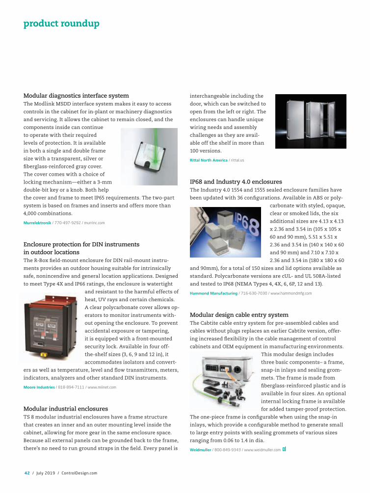
Modular diagnostics interface systemThe Modlink MSDD interface system makes it easy to access
controls in the cabinet for in-plant or machinery diagnostics
and servicing. It allows the cabinet to remain closed, and the
components inside can continue
to operate with their required
levels of protection. It is available
in both a single and double frame
size with a transparent, silver or
�berglass-reinforced gray cover.
The cover comes with a choice of
locking mechanism—either a 3-mm
double-bit key or a knob. Both help
the cover and frame to meet IP65 requirements. The two-part
system is based on frames and inserts and offers more than
4,000 combinations.
Murrelektronik / 770-497-9292 / murrinc.com
Enclosure protection for DIN instruments in outdoor locationsThe R-Box �eld-mount enclosure for DIN rail-mount instru-
ments provides an outdoor housing suitable for intrinsically
safe, nonincendive and general location applications. Designed
to meet Type 4X and IP66 ratings, the enclosure is watertight
and resistant to the harmful effects of
heat, UV rays and certain chemicals.
A clear polycarbonate cover allows op-
erators to monitor instruments with-
out opening the enclosure. To prevent
accidental exposure or tampering,
it is equipped with a front-mounted
security lock. Available in four off-
the-shelf sizes (3, 6, 9 and 12 in), it
accommodates isolators and convert-
ers as well as temperature, level and �ow transmitters, meters,
indicators, analyzers and other standard DIN instruments.
Moore Industries / 818-894-7111 / www.miinet.com
Modular industrial enclosuresTS 8 modular industrial enclosures have a frame structure
that creates an inner and an outer mounting level inside the
cabinet, allowing for more gear in the same enclosure space.
Because all external panels can be grounded back to the frame,
there’s no need to run ground straps in the �eld. Every panel is
interchangeable including the
door, which can be switched to
open from the left or right. The
enclosures can handle unique
wiring needs and assembly
challenges as they are avail-
able off the shelf in more than
100 versions.
Rittal North America / rittal.us
IP68 and Industry 4.0 enclosuresThe Industry 4.0 1554 and 1555 sealed enclosure families have
been updated with 36 con�gurations. Available in ABS or poly-
carbonate with styled, opaque,
clear or smoked lids, the six
additional sizes are 4.13 x 4.13
x 2.36 and 3.54 in (105 x 105 x
60 and 90 mm), 5.51 x 5.51 x
2.36 and 3.54 in (140 x 140 x 60
and 90 mm) and 7.10 x 7.10 x
2.36 and 3.54 in (180 x 180 x 60
and 90mm), for a total of 150 sizes and lid options available as
standard. Polycarbonate versions are cUL- and UL 508A-listed
and tested to IP68 (NEMA Types 4, 4X, 6, 6P, 12 and 13).
Hammond Manufacturing / 716-630-7030 / www.hammondmfg.com
Modular design cable entry systemThe Cabtite cable entry system for pre-assembled cables and
cables without plugs replaces an earlier Cabtite version, offer-
ing increased �exibility in the cable management of control
cabinets and OEM equipment in manufacturing environments.
This modular design includes
three basic components– a frame,
snap-in inlays and sealing grom-
mets. The frame is made from
�berglass-reinforced plastic and is
available in four sizes. An optional
internal locking frame is available
for added tamper-proof protection.
The one-piece frame is con�gurable when using the snap-in
inlays, which provide a con�gurable method to generate small
to large entry points with sealing grommets of various sizes
ranging from 0.06 to 1.4 in dia.
Weidmuller / 800-849-9343 / www.weidmuller.com
42 / July 2019 / ControlDesign.com
product roundup
CD1907_41_42_Roundup.indd 42 7/9/19 3:37 PM
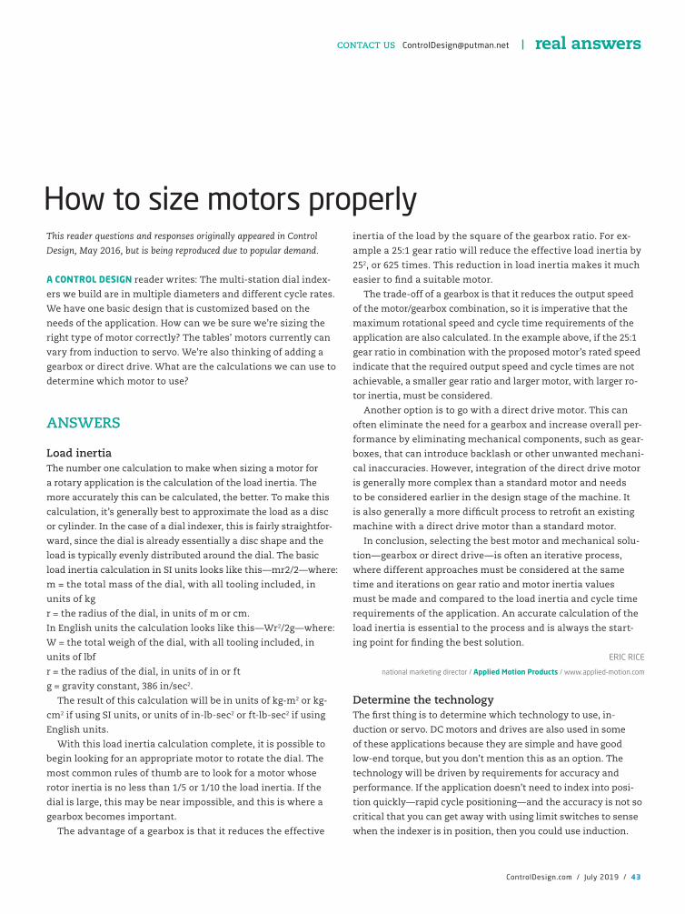
ControlDesign.com / July 2019 / 43
This reader questions and responses originally appeared in Control
Design, May 2016, but is being reproduced due to popular demand.
A CONTROL DESIGN reader writes: The multi-station dial index-
ers we build are in multiple diameters and different cycle rates.
We have one basic design that is customized based on the
needs of the application. How can we be sure we’re sizing the
right type of motor correctly? The tables’ motors currently can
vary from induction to servo. We’re also thinking of adding a
gearbox or direct drive. What are the calculations we can use to
determine which motor to use?
ANSWERS
Load inertiaThe number one calculation to make when sizing a motor for
a rotary application is the calculation of the load inertia. The
more accurately this can be calculated, the better. To make this
calculation, it’s generally best to approximate the load as a disc
or cylinder. In the case of a dial indexer, this is fairly straightfor-
ward, since the dial is already essentially a disc shape and the
load is typically evenly distributed around the dial. The basic
load inertia calculation in SI units looks like this—mr2/2—where:
m = the total mass of the dial, with all tooling included, in
units of kg
r = the radius of the dial, in units of m or cm.
In English units the calculation looks like this—Wr2/2g—where:
W = the total weigh of the dial, with all tooling included, in
units of lbf
r = the radius of the dial, in units of in or ft
g = gravity constant, 386 in/sec2.
The result of this calculation will be in units of kg-m2 or kg-
cm2 if using SI units, or units of in-lb-sec2 or ft-lb-sec2 if using
English units.
With this load inertia calculation complete, it is possible to
begin looking for an appropriate motor to rotate the dial. The
most common rules of thumb are to look for a motor whose
rotor inertia is no less than 1/5 or 1/10 the load inertia. If the
dial is large, this may be near impossible, and this is where a
gearbox becomes important.
The advantage of a gearbox is that it reduces the effective
inertia of the load by the square of the gearbox ratio. For ex-
ample a 25:1 gear ratio will reduce the effective load inertia by
252, or 625 times. This reduction in load inertia makes it much
easier to �nd a suitable motor.
The trade-off of a gearbox is that it reduces the output speed
of the motor/gearbox combination, so it is imperative that the
maximum rotational speed and cycle time requirements of the
application are also calculated. In the example above, if the 25:1
gear ratio in combination with the proposed motor’s rated speed
indicate that the required output speed and cycle times are not
achievable, a smaller gear ratio and larger motor, with larger ro-
tor inertia, must be considered.
Another option is to go with a direct drive motor. This can
often eliminate the need for a gearbox and increase overall per-
formance by eliminating mechanical components, such as gear-
boxes, that can introduce backlash or other unwanted mechani-
cal inaccuracies. However, integration of the direct drive motor
is generally more complex than a standard motor and needs
to be considered earlier in the design stage of the machine. It
is also generally a more dif�cult process to retro�t an existing
machine with a direct drive motor than a standard motor.
In conclusion, selecting the best motor and mechanical solu-
tion—gearbox or direct drive—is often an iterative process,
where different approaches must be considered at the same
time and iterations on gear ratio and motor inertia values
must be made and compared to the load inertia and cycle time
requirements of the application. An accurate calculation of the
load inertia is essential to the process and is always the start-
ing point for �nding the best solution.
ERIC RICE
national marketing director / Applied Motion Products / www.applied-motion.com
Determine the technologyThe �rst thing is to determine which technology to use, in-
duction or servo. DC motors and drives are also used in some
of these applications because they are simple and have good
low-end torque, but you don’t mention this as an option. The
technology will be driven by requirements for accuracy and
performance. If the application doesn’t need to index into posi-
tion quickly—rapid cycle positioning—and the accuracy is not so
critical that you can get away with using limit switches to sense
when the indexer is in position, then you could use induction.
How to size motors properly
real answersCONTACT US [email protected]
CD1907_43_46_RealAnswers.indd 43 7/9/19 3:38 PM
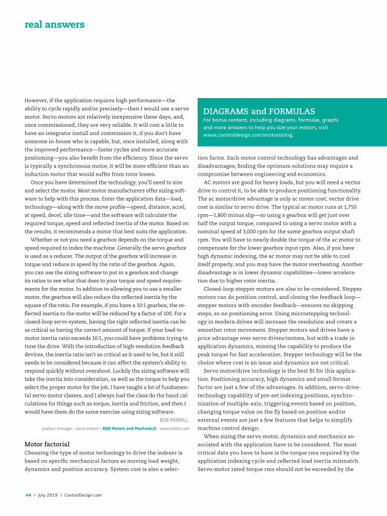
However, if the application requires high performance—the
ability to cycle rapidly and/or precisely—then I would use a servo
motor. Servo motors are relatively inexpensive these days, and,
once commissioned, they are very reliable. It will cost a little to
have an integrator install and commission it, if you don’t have
someone in-house who is capable, but, once installed, along with
the improved performance—faster cycles and more accurate
positioning—you also bene�t from the ef�ciency. Since the servo
is typically a synchronous motor, it will be more ef�cient than an
induction motor that would suffer from rotor losses.
Once you have determined the technology, you’ll need to size
and select the motor. Most motor manufacturers offer sizing soft-
ware to help with this process. Enter the application data—load,
technology—along with the move pro�le—speed, distance, accel,
at speed, decel, idle time—and the software will calculate the
required torque, speed and re�ected inertia of the motor. Based on
the results, it recommends a motor that best suits the application.
Whether or not you need a gearbox depends on the torque and
speed required to index the machine. Generally the servo gearbox
is used as a reducer. The output of the gearbox will increase in
torque and reduce in speed by the ratio of the gearbox. Again,
you can use the sizing software to put in a gearbox and change
its ratios to see what that does to your torque and speed require-
ments for the motor. In addition to allowing you to use a smaller
motor, the gearbox will also reduce the re�ected inertia by the
square of the ratio. For example, if you have a 10:1 gearbox, the re-
�ected inertia to the motor will be reduced by a factor of 100. For a
closed-loop servo system, having the right re�ected inertia can be
as critical as having the correct amount of torque. If your load-to-
motor inertia ratio exceeds 10:1, you could have problems trying to
tune the drive. With the introduction of high-resolution feedback
devices, the inertia ratio isn’t as critical as it used to be, but it still
needs to be considered because it can affect the system’s ability to
respond quickly without overshoot. Luckily the sizing software will
take the inertia into consideration, as well as the torque to help you
select the proper motor for the job. I have taught a lot of fundamen-
tal servo-motor classes, and I always had the class do the hand cal-
culations for things such as torque, inertia and friction, and then I
would have them do the same exercise using sizing software.
BOB MERRILL,
product manager – servo motors / ABB Motors and Mechanical / www.baldor.com
Motor factorialChoosing the type of motor technology to drive the indexer is
based on speci�c mechanical factors as moving load weight,
dynamics and position accuracy. System cost is also a selec-
tion factor. Each motor control technology has advantages and
disadvantages; �nding the optimum solutions may require a
compromise between engineering and economics.
AC motors are good for heavy loads, but you will need a vector
drive to control it, to be able to produce positioning functionality.
The ac motor/drive advantage is only ac motor cost; vector drive
cost is similar to servo drive. The typical ac motor runs at 1,750
rpm—1,800 minus slip—so using a gearbox will get just over
half the output torque, compared to using a servo motor with a
nominal speed of 3,000 rpm for the same gearbox output shaft
rpm. You will have to nearly double the torque of the ac motor to
compensate for the lower gearbox input rpm. Also, if you have
high dynamic indexing, the ac motor may not be able to cool
itself properly, and you may have the motor overheating. Another
disadvantage is in lower dynamic capabilities—lower accelera-
tion due to higher rotor inertia.
Closed-loop stepper motors are also to be considered. Stepper
motors can do position control, and closing the feedback loop—
stepper motors with encoder feedback—ensures no skipping
steps, so no positioning error. Using microstepping technol-
ogy in modern drives will increase the resolution and create a
smoother rotor movement. Stepper motors and drives have a
price advantage over servo drives/motors, but with a trade in
application dynamics, missing the capability to produce the
peak torque for fast acceleration. Stepper technology will be the
choice where cost is an issue and dynamics are not critical.
Servo motor/drive technology is the best �t for this applica-
tion. Positioning accuracy, high dynamics and small format
factor are just a few of the advantages. In addition, servo-drive-
technology capability of pre-set indexing positions, synchro-
nization of multiple-axis, triggering events based on position,
changing torque value on the �y based on position and/or
external events are just a few features that helps to simplify
machine control design.
When sizing the servo motor, dynamics and mechanics as-
sociated with the application have to be considered. The most
critical data you have to have is the torque rms required by the
application indexing cycle and re�ected load inertia mismatch.
Servo-motor rated torque rms should not be exceeded by the
44 / July 2019 / ControlDesign.com
real answers
DIAGRAMS and FORMULASFor bonus content, including diagrams, formulas, graphs and more answers to help you size your motors, visit www.controldesign.com/motorsizing.
CD1907_43_46_RealAnswers.indd 44 7/9/19 3:39 PM

application indexing cycle required torque rms (TRMS).
Calculation of the TRMS required for the indexing cycle is
based on the formula—(TRMS)2 = (T1
2t1+ T22t2+ T3
2t3+…Tn2tn)/( t1+
t2+ t3+…tn)—where T is torque associated with acquiring/main-
taining desired velocity and t is time duration corresponding
to movement. Please include in the indexing cycle the moving
pro�le and the dwell time until the next cycle is starting.
The servo motor’s main feature is the capability to develop
peak torque for 1-3 seconds, so for an indexing application the
entire move is usually only acceleration/deceleration, with ac-
celeration using the peak torque of the motor.
The servo drive associated with the motor has to be able to
deliver the peak current needed to power the servo motor peak
torque. If the servo motor peak torque requires more current than
the servo drive peak current is rated, the servo drive will protect
itself from going overcurrent; that may either reduce the current
output—current limitation—or trip in overcurrent protection.
Neither of the two situations will provide suf�cient current for
the motor peak torque, so the motor will not be able to reach the
required acceleration. Pay attention to the time associated with
the servo drive peak current; it has to be at least suf�cient to cover
your longest acceleration time at peak torque or the drive may trip
in thermal protection or go in current limitation—3 seconds if the
motor peak torque is 3 seconds.
Inertia mismatch is the re�ected load inertia to servo-motor
rotor. The higher inertia mismatch, the slower the response
time from the motor. Inertia mismatch can be anywhere
between 1:1 and 100:1, or it can be even higher if acceleration/
deceleration times are long and you can live with a sluggish
system response. For a dial indexer where acceleration/decel-
eration and positioning in a 30º-60º range is close to 1 second, a
20:1 inertia mismatch should be suf�cient.
Using a gearbox will decrease the re�ected inertia, divided
by the gearbox ratio and allow for a better usage of the servo
motor. Servo-motor best torque usage is at the maximum speed
before torque is starting to decrease—typically, 3,000 rpm. Us-
ing a 10:1 gearbox, for example, will multiply the motor torque
10 times, decrease inertia mismatch 10 times and allow the
motor to reach higher operation speed. From the cost point of
view, adding the gearbox will be compensated by reduced cost
of smaller-size servo motor, servo drive and probably cables.
On the servo motor torque graph, the peak torque knee is at
3,000 rpm.
Environment vibrations and/or temperature: For high vibra-
tions and temperature variations, a resolver feedback on the
servo motor will be better than an encoder with glass disk.
Backlash associated with the gearbox: It will affect positioning
accuracy. Using a low-backlash planetary will create a typical
positioning error of 3 arcmin (0.05°).
The easiest way to size your servo motor is using the sizing
software of the servo motor/drive manufacturer. The software
can also select additional mechanical components.
Critical data, such as precision accuracy at the end of travel,
can be calculated and documented. One advantage of the
servo software is that it is looking at application vs. capa-
bility of the entire servo system verifying for example that
the servo-drive selection has suf�cient thermal capability
to handle the peak current of the indexing cycle, offering in
the �nal selection different packages with different system
loading capability. This load capacity can be very important in
designing different load/cycle variations of the same machine,
especially when some input data can change in time, such as
friction due to poor machine maintenance.
The technical report on the system selection that the sizing
software provides is a complex document with application-
sizing data and motor, drive, gearbox and actuator technical
data, as well as device loadings for the speci�c application.
The report eliminates the errors in auxiliary components
needed, such as connector size on system cables or adapting
�ange for gearbox/servo motor.
The bill of material (BOM) with all of the correct part num-
bers and quantities can be also provided, making the PO docu-
mentation really easy to process and error-free.
PAUL PLAVICHEANU
EA REGIONAL PRODUCT MANAGER / Region Americas, Festo Americas /
www.festo.com/us
Calculate, calculate, calculateSince there is one design that is customized based on the vari-
ous dial indexers and different cycle rates, calculations will
need to be done for each unique application. However, in a situ-
ation where a single motor is required and the system will be
varied, select the worst-case scenario—largest diameter with
fastest cycle rate—when sizing.
First, calculate for the inertia of all components being used.
The inertia should be calculated �rst as the inertia value will be
used later to calculate for the torque. To calculate inertia of the
dial, use the following equation: JD= (1/8)mD2, where m is the
weight of the dial in ounces and D is the diameter of the dial in
inches. If the weight is unknown, then the inertia can be calcu-
lated by using the dial thickness and material density. The equa-
tion to use is: JD= (π/32) LD4, where = material density in oz-in3,
ControlDesign.com / July 2019 / 45
DIAGRAMS and FORMULASFor bonus content, including diagrams, formulas, graphs and more answers to help you size your motors, visit www.controldesign.com/motorsizing.
CD1907_43_46_RealAnswers.indd 45 7/9/19 3:39 PM
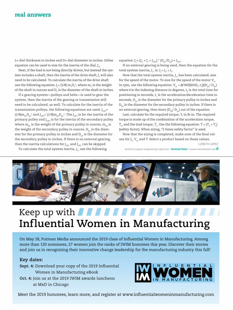
real answers
L= dial thickness in inches and D= dial diameter in inches. Either
equation can be used to size for the inertia of the dial, JD.
Next, if the load is not being directly driven, but instead the sys-
tem includes a shaft, then the inertia of the drive shaft, Js will also
need to be calculated. To calculate the inertia of the drive shaft
use the following equation: Js= (1/8) m2D22, where m2 is the weight
of the shaft in ounces and D2 is the diameter of the shaft in inches.
If a gearing system—pulleys and belts—is used to gear the
system, then the inertia of the gearing or transmission will
need to be calculated, as well. To calculate for the inertia of the
transmission pulleys, the following equations are used: JDP1=
(1/8)mp1Dp12 and JDP2= (1/8)mp2Dp2
2. The JDP1 is for the inertia of the
primary pulley and JDP2 is for the inertia of the secondary pulley
where mp1 is the weight of the primary pulley in ounces, mp2 is
the weight of the secondary pulley in ounces, Dp1 is the diam-
eter for the primary pulley in inches and Dp2 is the diameter for
the secondary pulley in inches. If there is no external gearing,
then the inertia calculations for JDP1 and JDP2 can be skipped.
To calculate the total system inertia, JL, use the following
equation: JL= (JD + Js + JDP2) * (Dp1/Dp2) + JDP1.
If no external gearing is being used, then the equation for the
total system inertia, JL, is: JL= JD + Js.
Now that the total system inertia, JL, has been calculated, size
for the speed of the motor. To size for the speed of the motor Vm
in rpm, use the following equation: Vm = ( /360)(60/(t0-t1))(Dp2/ Dp1)
where is the indexing distance in degrees, t0 is the total time for
positioning in seconds, t1 is the acceleration/deceleration time in
seconds, Dp1 is the diameter for the primary pulley in inches and
Dp2 is the diameter for the secondary pulley in inches. If there is
no external gearing, then leave (Dp2/ Dp1) out of the equation.
Last, calculate for the required torque, T, in lb-in. The required
torque is made up of the combination of the acceleration torque,
Ta, and the load torque, TL. Use the following equation: T = (Ta + TL)
(safety factor). When sizing, “2 times safety factor” is used.
Now that the sizing is completed, make note of the � nal val-
ues for JL, Vm and T. Select a product based on those values.
LIZBETH LOPEZ
technical support engineering supervisor / Oriental Motor / www.orientalmotor.com
Meet the 2019 honorees, learn more, and register at www.in�uentialwomeninmanufacturing.com
Key dates:Sept. 4: Download your copy of the 2019 In�uential
Women in Manufacturing eBook
Oct. 4: Join us at the 2019 IWIM awards luncheon
at MxD in Chicago
On May 28, Putman Media announced the 2019 class of In�uential Women in Manufacturing. Among more than 120 nominees, 27 women join the ranks of IWIM honorees this year. Discover their stories and join us in recognizing their innovative change leadership for the manufacturing industry this fall!
Keep up with Influential Women in Manufacturing
CD1907_43_46_RealAnswers.indd 46 7/9/19 3:39 PM

Collaborative robotsThis series of power- and force-limiting collaborative robots
can handle 4- to 35-kg payloads and a 550- to 1,813-mm reach.
Easy to use, even for those with little or no experience, the
cobots are equipped with an iHMI intuitive touchscreen user
interface that includes step-by-step programming instructions
right from the
teach pendant.
The hand guid-
ance feature
allows operators
to teach a collab-
orative robot by
leading it through
paths at the press
of a button or use it to lift heavy objects manually. The six co-
bot models combine automation technology and sensitive built-
in sensors that allow them to work safely alongside people in a
variety of industrial jobs.
Fanuc America / 888-326-8287 / www.fanucamerica.com
Voice coil motor with internal shaft and bearingThe GVCM-051-127-01 linear dc voice coil motor has an internal
shaft and bearing. The 3.75-in (95.3-mm) stroke of the preci-
sion-ground 0.236-in- (6-mm-) diameter shaft with an internal
thread is guided by a long-life plain bearing that allow side
loads up to 1 lb (4.4 N). The motor has threaded mounting holes
in the housing and coil ends for easy integration into exist-
ing and future applications. This brushless actuator features
high speed, high acceleration and deceleration, zero
backlash, high accuracy, high repeatability and
a high force-to-size ratio of 5 lb (22.2 N) of
continuous force and 15.8 lb (70.3 N) of
peak force in either direction.
Moticont / 818-785-1800 / http://moticont.com
Pancake cylindersThe DPC family of inch series “pancake” cylinders offer high
force and short stroke for tight spaces. The DPCA for new ma-
chines has an aluminum body and is clear-anodized for corro-
sion resistance. The DPCB is designed for maintenance, repair
and operations (MRO) applications with drop-in compatibility
to other manufacturers. It features a hard chrome-plated
stainless steel piston rod and a nonmetallic composite rod
bushing. Both prelubricated models
feature a choice of eight bore sizes
and variable stroke lengths up
to 4 in. Magnetic piston options
are available for cylinder position
sensing, as are sensors and other
accessories such as clevises. Cus-
tom cylinders also are available.
Festo / www.festo.com
Ultrasonic sensors for object detectionThe RU50 Eco series has been expanded to include analog
variants. The sensors have a plastic threaded barrel made
of durable liquid crystal polymer and a sensing range of 500
mm. They use sonic transducer technology for object detec-
tion. Teachable switching points and sensing distance ensure
users can con�gure the sensors to detect objects between the
sensor and the reference point. Even bad lighting conditions
and glossy or re�ective surfaces have no in�uence on the sen-
sor. PNP and NPN switching versions
as well as analog 4-20 mA and
0-10 V are available. Output
options include an M12 con-
nector or a 2-m cable.
Turck / www.turck.us
Motorized high-resolution pan-tilt stagesThese high-resolution, motorized pan-tilt
stages are available in two sizes. The PT60-1
pan-tilt stage is a combination of two
60-mm (2.362-in) rotary stages, and the
PT100-1 is a combination of two
100-mm (3.937-in) rotary stages
set at a 90° angle to each other.
Each has rotary stages that feature
repeatability of 0.005° (18 arc-sec), a
positional accuracy of 0.005° (18 arc-
sec) and a resolution of 0.001° = 3.6 in
(10 micro-steps per step motor driver in use). These compact,
easily integrated stages weigh 2 kg (4.4 lb) for the PT60-1 and
4.4 kg (9.75 lb) for the PT100-1. Load capacities are 10 kg (22 lb)
and 20 kg (44 lb), respectively).
Optimal Engineering Systems / 818-222-9200 / www.oesincorp.com
ControlDesign.com / July 2019 / 47
product showcaseCONTACT US [email protected]
CD1907_47_49_Showcase.indd 47 7/9/19 3:41 PM
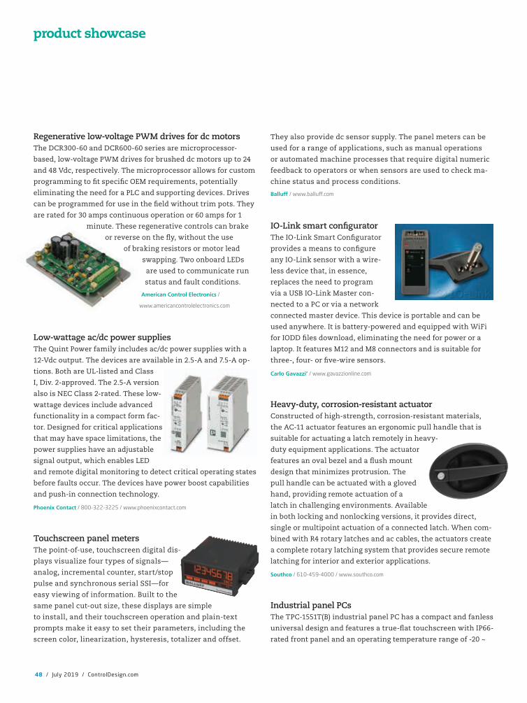
Regenerative low-voltage PWM drives for dc motorsThe DCR300-60 and DCR600-60 series are microprocessor-
based, low-voltage PWM drives for brushed dc motors up to 24
and 48 Vdc, respectively. The microprocessor allows for custom
programming to �t speci�c OEM requirements, potentially
eliminating the need for a PLC and supporting devices. Drives
can be programmed for use in the �eld without trim pots. They
are rated for 30 amps continuous operation or 60 amps for 1
minute. These regenerative controls can brake
or reverse on the �y, without the use
of braking resistors or motor lead
swapping. Two onboard LEDs
are used to communicate run
status and fault conditions.
American Control Electronics /
www.americancontrolelectronics.com
Low-wattage ac/dc power suppliesThe Quint Power family includes ac/dc power supplies with a
12-Vdc output. The devices are available in 2.5-A and 7.5-A op-
tions. Both are UL-listed and Class
I, Div. 2-approved. The 2.5-A version
also is NEC Class 2-rated. These low-
wattage devices include advanced
functionality in a compact form fac-
tor. Designed for critical applications
that may have space limitations, the
power supplies have an adjustable
signal output, which enables LED
and remote digital monitoring to detect critical operating states
before faults occur. The devices have power boost capabilities
and push-in connection technology.
Phoenix Contact / 800-322-3225 / www.phoenixcontact.com
Touchscreen panel metersThe point-of-use, touchscreen digital dis-
plays visualize four types of signals—
analog, incremental counter, start/stop
pulse and synchronous serial SSI—for
easy viewing of information. Built to the
same panel cut-out size, these displays are simple
to install, and their touchscreen operation and plain-text
prompts make it easy to set their parameters, including the
screen color, linearization, hysteresis, totalizer and offset.
They also provide dc sensor supply. The panel meters can be
used for a range of applications, such as manual operations
or automated machine processes that require digital numeric
feedback to operators or when sensors are used to check ma-
chine status and process conditions.
Balluff / www.ballu�.com
IO-Link smart con�guratorThe IO-Link Smart Con�gurator
provides a means to con�gure
any IO-Link sensor with a wire-
less device that, in essence,
replaces the need to program
via a USB IO-Link Master con-
nected to a PC or via a network
connected master device. This device is portable and can be
used anywhere. It is battery-powered and equipped with WiFi
for IODD �les download, eliminating the need for power or a
laptop. It features M12 and M8 connectors and is suitable for
three-, four- or �ve-wire sensors.
Carlo Gavazzi’ / www.gavazzionline.com
Heavy-duty, corrosion-resistant actuatorConstructed of high-strength, corrosion-resistant materials,
the AC-11 actuator features an ergonomic pull handle that is
suitable for actuating a latch remotely in heavy-
duty equipment applications. The actuator
features an oval bezel and a �ush mount
design that minimizes protrusion. The
pull handle can be actuated with a gloved
hand, providing remote actuation of a
latch in challenging environments. Available
in both locking and nonlocking versions, it provides direct,
single or multipoint actuation of a connected latch. When com-
bined with R4 rotary latches and ac cables, the actuators create
a complete rotary latching system that provides secure remote
latching for interior and exterior applications.
Southco / 610-459-4000 / www.southco.com
Industrial panel PCsThe TPC-1551T(B) industrial panel PC has a compact and fanless
universal design and features a true-�at touchscreen with IP66-
rated front panel and an operating temperature range of -20 ~
48 / July 2019 / ControlDesign.com
product showcase
CD1907_47_49_Showcase.indd 48 7/9/19 3:41 PM

60 °C (-4 ~ 140 °F). It is equipped with an Intel Atom E3845 quad-core pro-
cessor for enhanced computing performance. In addition to the system’s
two serial ports, four USBs and two GbE Intel I210 LANs for enhanced
communication, it includes an iDoor socket, HDD/SDD bay and mPCIE
port with mSATA support for easy system expansion. It is compatible
with a standard VESA arm mount (100 x 100 mm).
Advantech / www.advantech.com
DIN rail mount redundancy moduleThe DRM40 series DIN rail mount redundancy modules are two 20-A
10- to 30-Vdc-rated inputs that can be connected to provide a 20-A re-
dundant con�guration or, using the load-balancing option, to deliver a
40-A output. For capacitive and inductive loads, the module will sup-
port an additional 50% peak load for four seconds. The use of low-loss
MOSFET reverse current protection devices reduces the internal volt-
age drop to just 200 mV. If the input currents are unbalanced, the front panel-mounted LED is off.
When the input voltages are adjusted and the load current is shared equally, the LED is illuminated.
TDK-Lambda Americas / 800-lambda-4 / www.tdk-lambda.com
Cut-to-length bulk sensor/actuator cableFlexible multiconductor sensor/actuator cable is available in 24 AWG
and 22 AWG with three, four or �ve unshielded conductors and
in customer-speci�ed 1-ft-increment lengths. Individual conduc-
tors are stranded bare copper for �exibility, with color-coded PVC
insulation for easy identi�cation. The cable outer jacket is a �exible
PVC available in either gray or yellow, and the jacket is pressure
extruded for optimal roundness. The cable is UL-listed and has CSA approval and is suitable for
both stationary and �exible industrial factory automation applications with limited mechanical
stress and free movement without any tensile stress, loads or forced movements. It is not suit-
able for continuous �exing applications.
AutomationDirect / 800-633-0405 / www.automationdirect.com
Free-core and spring-loaded LVDTThis dc LVDT technology offers expanded output capabilities to
meet the needs of industrial monitoring and feedback applications.
In addition to the 4-20 mA versions of the free-core and spring-
loaded LVDTs, customized 4-20 mA position sensors are available.
The 4-20 mA loop-powered LVDTs are suitable for use in robotic
automation and industrial automation controls. The output signal provided by the sensors in-
tegrates with a variety of PLCs, digital indicators, computer-based data processors and QC data
collection systems. Hermetically sealed versions of the free-core and spring-loaded LVDTs can
withstand dirt, water, steam and other harsh elements.
NewTek Sensor Solutions / www.newteksensors.com
ControlDesign.com / July 2019 / 49
publishing teamgroup publisher & vp, content
Keith Larson [email protected]
vp, sales & publishing director
sales teamnortheastern and mid-atlantic regional manager
Dave Fisher [email protected]
508/543-5172 Fax: 508/543-3061
24 Cannon Forge Dr.
Foxboro, Massachusetts 02035
midwestern and southern regional manager
Greg Zamin [email protected]
704/256-5433 Fax: 704/256-5434
1501 E. Woodfield Rd., Suite 400N
Schaumburg, Illinois 60173
western and mountain regional manager
Jeff Mylin [email protected]
847/516-5879 Fax: 630/625-1124
digital sales specialist
Jeanne Freedland
805/773-4299 Fax: 805/773-0451
classified manager
Lori Goldberg [email protected]
630/467-1300 Fax: 630/467-1124
executive staffpresident & ceo
John M. Cappelletti
cfo
Rick Kasper
vp, creative services, production
Steve Herner
reprintsFoster Reprints • www.fosterprinting.com
Jill Kaletha
866-879-9144 ext. 194
The only magazine exclusively
dedicated to the original equipment manufactur-
ing (OEM) market for
instrumentation and controls—the
largest market for industrial controls.
1501 E. Woodfield Rd., Suite 400N
Schaumburg, Illinois 60173
630/467-1300
Fax: 630/467-1124
CD1907_47_49_Showcase.indd 49 7/9/19 3:41 PM
WHEN DISCUSSING THE physics of linear motion, rotary and
oscillating motion often surface, as well. Linear motion is more
than just displacement; it has a start and a stop point, and
compressed air and rotary motion often drive the physics of the
move and the resulting cycle time.
Fortunately, calculus is not needed to calculate linear motion
as it is simpli� ed by assuming a constant acceleration. The
equations for linear motion and the related variables including
constant acceleration, displacement, velocity and time are eas-
ily accessible.
Linear-motion automation compo-
nents, such as pneumatic actuators
and motor-driven actuators, all oper-
ate within the de� ned physics equa-
tions. All motion starts and stops,
but some are easy to create multiples
of such. Most provide the ability to
adjust positions of the start and stop points, but accuracy and
repeatability vary, and some are programmable.
Linear motion, moving the part or tooling, is initiated and
stopped in many ways. Compressed air and rotary motion are
two of the most common methods used on automated equip-
ment, and each method controls the motion in different ways.
The compressed air controlled through air-preparation units,
solenoids, tubes and � ow controls actuates cylinders and pneu-
matic actuators. This pneumatic actuated linear motion usually
only has two positions, such as advanced/ returned, extended/
retracted, raised/ lowered or open/ closed. The advanced and
returned displacement—the start and stop position—can be
adjusted, and the speed of the move can be varied.
Simple pneumatic linear motion literally runs into hard stops
at each end of travel; the travel is often � xed. These hard stops
can be built internally to the cylinder or actuator or mounted
externally either to the device itself or surrounding support
structure. In any case, it’s good practice to decelerate and even
stop the cylinder piston before impacting the end cap. As the
speed of the motion increases, external shock absorbers or
soft-bump stops are often used to control the stopping of the
actuator at the end of travel.
System air pressure, solenoid valve and hose size, and the
air volume through a � ow control all combine to determine
pneumatic-actuator velocity and acceleration. These actua-
tors often accelerate the whole motion before hitting the hard
stop. Obviously, machine cycle time drives the actuator speed
requirements, but the cylinder speed should only be set as fast
as needed. Adjusting the � ow control to reduce the speed can
greatly soften the abrupt stops at the end of travel.
The repeatability of the hard-stop positioning is well under
0.01 inch, but adjusting it to an accurate position can be dif-
� cult. Moving the advanced or retracted position of an end-of-
travel stop by loosening a nut, turning a bolt and retightening
the nut may require several tries to
get within a few thousandths of an
inch of the desired position.
Better control of the linear motion
speed, acceleration and starting
and stopping positions is possible
by adding rotary motion to an ap-
propriate linear motion actuator
instead of compressed air. Improved precision and gentler op-
eration can be had using rotary motion via a variable-frequency
dive (VFD) and motor, stepper motor and servo motor. And
there are other differences.
To start, these motor-driven linear actuators are not sup-
posed to run into hard stops. That would be a crash condition,
and certainly not a gentle-stop method. It may even damage
the actuator or the carriage and bearings in the device. The
controlling drives and automation controllers are programmed
to move the carriage between the hard stops in this case, with-
out contacting them.
Another difference is that end-of-travel switches on motor-
driven linear actuators are not meant to be actuated during
normal operation such as advanced and returned sensors are
on pneumatic actuators. Activating end-of-travel switches on
a motor-driven actuator will usually cause the motor drive to
perform an immediate stop before reaching a hard stop.
In more precise applications, such as moving between two
or more programmable points, a home switch is part of the
precise and gentle stopping performance of these motor-driven
linear actuators. Open-loop control, such as step and direction
signals to a stepper motor drive or closed-loop control such as
encoder feedback to the servo motor drive, allow programming
of target positions that are then reached via a discrete signal,
analog voltage or controller instruction block.
Be gentle and accurate with linear motion
50 / July 2019 / ControlDesign.com
Dave Perkontechnical editor
automation basics
The linear motion is stopped differently in pneumatic actuators
and motor-driven actuators.
CD1907_50_AutoBasics.indd 50 7/9/19 3:42 PM

For additional information, please contact Foster Printing Service, the official reprint
provider for Control Design.
Give yourself a competitive advantage with reprints. Call us today!
PMS 370 C
C: 60M: 0Y: 100K: 28
Call 866.879.9144 or [email protected]
Use reprints to maximize your marketing initiatives and strengthen your brand’s value.Custom reprint products of articles and features from Control Design create powerful marketing tools that serve as instantly credible endorsements.
Reprints are a simple way to put information directly into the hands of your target audience. Having been featured in a well-respected publication adds the credibility of a third-party endorsement to your message.
REPRINTS ARE IDEAL FOR:
n New Product Announcements
n Sales Aid For Your Field Force
n PR Materials & Media Kits
n Direct Mail Enclosures
n Customer & Prospect Communications/Presentations
n Trade Shows/Promotional Events
n Conferences & Speaking Engagements
n Recruitment & Training Packages
CUSTOM REPRINTS
CD1907_FPA.indd 51 7/9/19 3:18 PM

190318_AutoC_CTRL_US.indd 1 3/18/19 2:51 PMCD1907_FPA.indd 52 7/8/19 6:30 PM