the airborne internet - opencdn.intechopen.com/pdfs/20441/intech-the_airborne... · 2018-09-25 ·...
TRANSCRIPT
17
The Airborne Internet
Daniel Medina and Felix Hoffmann German Aerospace Center (DLR)
Oberpfaffenhofen, Germany
1. Introduction
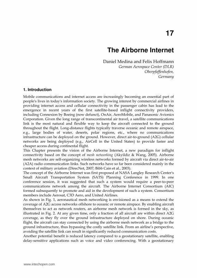
Mobile communications and internet access are increasingly becoming an essential part of people's lives in today's information society. The growing interest by commercial airlines in providing internet access and cellular connectivity in the passenger cabin has lead to the emergence in recent years of the first satellite-based inflight connectivity providers, including Connexion by Boeing (now defunct), OnAir, AeroMobile, and Panasonic Avionics Corporation. Given the long range of transcontinental air travel, a satellite communications link is the most natural and flexible way to keep the aircraft connected to the ground throughout the flight. Long-distance flights typically traverse oceanic and remote airspace, e.g., large bodies of water, deserts, polar regions, etc., where no communications infrastructure can be deployed on the ground. However, direct air-to-ground (A2G) cellular networks are being deployed (e.g., AirCell in the United States) to provide faster and cheaper access during continental flight. This Chapter presents the vision of the Airborne Internet, a new paradigm for inflight connectivity based on the concept of mesh networking (Akyildiz & Wang, 2005). Airborne mesh networks are self-organizing wireless networks formed by aircraft via direct air-to-air (A2A) radio communication links. Such networks have so far been considered mainly in the context of military aviation (DirecNet, 2007; Bibb Cain et al., 2003). The concept of the Airborne Internet was first proposed at NASA Langley Research Center's Small Aircraft Transportation System (SATS) Planning Conference in 1999. In one conference session, it was suggested that such a system would require a peer-to-peer communications network among the aircraft. The Airborne Internet Consortium (AIC) formed subsequently to promote and aid in the development of such a system. Consortium members include Aerosat, C3D Aero, and United Airlines. As shown in Fig. 1, aeronautical mesh networking is envisioned as a means to extend the coverage of A2G access networks offshore to oceanic or remote airspace. By enabling aircraft themselves to act as network routers, an airborne mesh network is formed in the sky, as illustrated in Fig. 2. At any given time, only a fraction of all aircraft are within direct A2G coverage, as they fly over the ground infrastructure deployed on shore. During oceanic flight, the aircraft can stay connected by using the airborne mesh network as a bridge to the ground infrastructure, thus bypassing the costly satellite link. From an airline’s perspective, avoiding the satellite link can result in significantly reduced communication costs. Another potential benefit is reduced latency compared to a geostationary satellite, enabling delay-sensitive applications such as voice and video conferencing. With a geostationary
www.intechopen.com
Future Aeronautical Communications
350
satellite, there is always a one-way end-to-end propagation delay of approximately 250 ms, required for the signal to travel up and down from the satellite. In the airborne mesh network, lower end-to-end delay guarantees can be provided by making use of appropriate Quality-of-Service (QoS) mechanisms, such as radio resource reservation or packet prioritization.
Fig. 1. Evolution from satellite-based to air-to-ground (A2G) inflight connectivity service provision via airborne mesh networking.
Fig. 2. The vision of an Airborne Internet over the North Atlantic.
www.intechopen.com

The Airborne Internet
351
Initially, an airline may rely only on its own aircraft for mesh networking, since it may be the only airline equipped with the required airborne technology (e.g., antenna, router, etc.). In the longer term, as more and more airlines equip for airborne mesh networking, airline partnerships may be formed to allow their aircraft to mesh together in a single unified cooperative network, building a more richly connected network. The North Atlantic is the busiest oceanic airspace in the world, and thus constitutes the best candidate scenario for a real deployment of an aeronautical mesh network. In 2007 approximately 425,000 flights crossed the North Atlantic (International Civil Aviation Organization [ICAO], 2008). As a result of passenger demand, time zone differences and airport noise restrictions, much of the North Atlantic air traffic contributes to two major alternating flows: a westbound flow departing Europe in the morning, and an eastbound flow departing North America in the evening. As shown in Fig. 3, the effect of these flows is to concentrate most of the traffic unidirectionally, with peak westbound traffic crossing the 30W longitude between 1130 UTC and 1900 UTC and peak eastbound traffic crossing the 30W longitude between 0100 UTC and 0800 UTC. Compared to terrestrial mesh networks, the fact that nodes are airborne rather than on the ground makes it possible to communicate over long ranges with unobstructed line-of-sight propagation characteristics. Moreover, nodes are moving at high speeds, giving rise to a rapidly changing network topology. The maximum communication range in aeronautical mesh networks is constrained by the spherical geometry of the network, as nodes fly very close to the earth surface. The line-of-sight (LOS) communication range is determined by the radio horizon. Within the horizon, atmospheric propagation is essentially subject to free space loss. Attenuation by clouds, rain, etc., can be negligible depending on the frequency spectrum used. Beyond the line-of-sight range, fading due to the earth's obstruction leads to very rapid attenuation (International Telecommunications Union [ITU], 1986).
Fig. 3. Number of aircraft in the North Atlantic Corridor throughout the day.
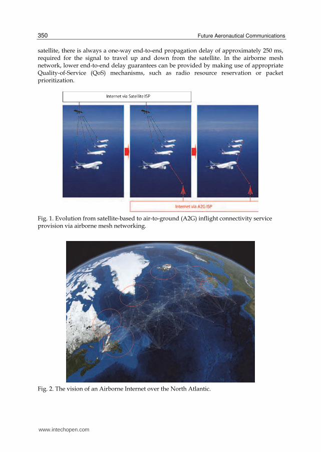
The LOS communication range between two nodes depends on the nodes' flight level and the characteristics of the terrain. In an oceanic environment, the earth surface can be approximated by a perfect sphere, as shown in Fig. 4.
www.intechopen.com
Future Aeronautical Communications
352
Fig. 4. Line-of-sight (LOS) range.
Given this geometry, Pythagoras' theorem can be used to obtain the LOS communication range
2 21 2 1 1 2 2 2 2e er r r h R h h R h (1)
where Re is the earth radius and h1 and h2 denote the flight altitude of each aircraft. Typical flight levels for transatlantic flights are between FL310 (31000 ft) and FL400 (40000 ft). For simplicity, we will assume that all aircraft fly at the same altitude h and ground stations are deployed at sea level. Thus, the A2G LOS communication range rG is given by
2 2G er h R h (2)
and the LOS communication range r between two airborne nodes is
2 Gr r (3)
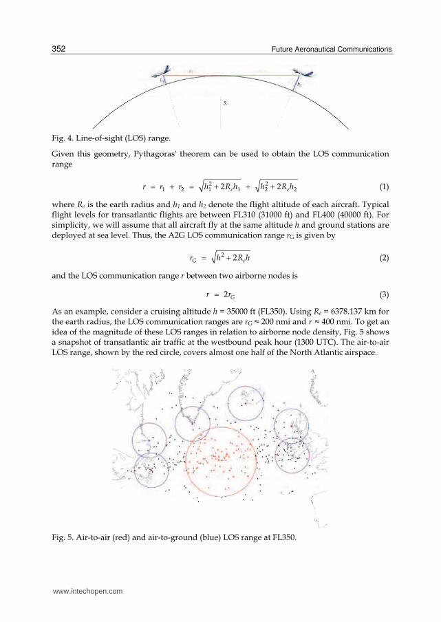
As an example, consider a cruising altitude h = 35000 ft (FL350). Using Re = 6378.137 km for the earth radius, the LOS communication ranges are rG ≈ 200 nmi and r ≈ 400 nmi. To get an idea of the magnitude of these LOS ranges in relation to airborne node density, Fig. 5 shows a snapshot of transatlantic air traffic at the westbound peak hour (1300 UTC). The air-to-air LOS range, shown by the red circle, covers almost one half of the North Atlantic airspace.
Fig. 5. Air-to-air (red) and air-to-ground (blue) LOS range at FL350.
www.intechopen.com
The Airborne Internet
353
Of course, the nominal communication range may be smaller than the LOS range, depending on the transmit power, the characteristics of the antenna, the modulation (data rate) used for transmission, and the target bit error rate (BER). The AeroSat Corporation, together with the U.S. Federal Aviation Administration (FAA), has performed flight trials with mechanically steered Ku-band antennas, demonstrating A2G link data rates of up to 45 Mbps over 150 nautical miles with a BER of 5.10-5 (McNary, 2007). Looking forward, we believe smart antennas to be the most appropriate technology for broadband airborne mesh networking, since they allow a node to quickly change the direction(s) in which it transmits/receives to/from its various neighbors and optimize the signal-to-interference ratio at the receiver (Bhobe & Perini, 2001). Broadband airborne mesh networks require a medium access control (MAC) protocol capable of handling high traffic loads in the network and providing QoS guarantees to communicating nodes. Carrier sense multiple access (CSMA) techniques are inappropriate in this environment, given the long propagation delay (a couple milliseconds) and the directional nature of radio transmissions. Aircraft are equipped with GPS for navigation purposes, and this provides a global time reference that can be exploited for synchronization among network nodes, e.g., to schedule collision-free transmissions in a time division multiple access (TDMA) fashion (Nelson & Kleinrock, 1985). In this Chapter, we propose a novel routing strategy that takes into account the specific nature of aeronautical mesh networks. A number of observations have guided our design. The airborne mesh network is connected to the ground at potentially multiple geographically distributed access points (Internet Gateways) via a rapidly changing number of short-lived bandwidth-limited A2G links, through which all internet traffic enters/leaves the airborne leaf network. We envision passengers consuming (rather than producing) great amounts of information, resulting in a considerable aggregate downstream traffic volume being delivered to the airborne network from the Internet Gateways. Thus, the Internet Gateways pose a capacity bottleneck, limiting the maximum bandwidth that can be offered to the aircraft. At any given time, an aircraft may be able to reach multiple Internet Gateways via a number of disjoint paths. This path diversity can be exploited to reduce congestion at the bottleneck A2G links. Our proposed strategy, Geographic Load Share Routing (GLSR), exploits the aircraft’s position information (e.g., made available through GPS) together with buffer size information to fully exploit the total A2G capacity available at any time to the airborne network by balancing the aggregate traffic load among all A2G links. The remainder of this Chapter is structured as follows. Section 2 provides references to related work. Section 3 describes our network model, including the antenna and interference model used in our simulations. In Section 4, we formulate a joint routing and scheduling optimization problem to minimize the average packet delay in the network. Section 5 briefly describes the link scheduling algorithm used to assign capacity to network links. Our proposed routing strategy is presented in Section 6, followed by a maximum throughput analysis in Section 7. Our simulation results are presented and discussed in Section 8. Finally, Section 9 concludes the Chapter.
2. Related work
Although a great number of routing protocols have been proposed for wireless mesh networks (Akyildiz & Wang, 2005), to the best of our knowledge none of them has been designed with the specific goal of aeronautical mesh networking in mind, and therefore they
www.intechopen.com
Future Aeronautical Communications
354
do not exploit the distinct characteristics of this environment. Only very recently has some attention been drawn to the application of multihop wireless networking to aviation (Sakhaee & Jamalipour, 2006; Sakhaee et al., 2006; Iordanakis et al., 2006; Tu & Shimamoto, 2009). However, these authors have a different focus and relatively simple network models. In previous work (Medina et al., 2008a; Medina et al., 2008b), we conducted simulations of realistic air traffic to study the feasibility and characterize the topology of such networks. For an excellent survey on geographic routing, see (Mauve et al., 2001). (He et al., 2003) proposed SPEED, a stateless protocol for real-time communication in wireless sensor networks. SPEED uses a geographic forwarding strategy similar to our own, which we already presented in (Medina et al., 2010) and forms part of the overall routing strategy presented here. Internet Gateway selection in mobile ad hoc networks is addressed in (Sun et al., 2002; Huang et al., 2003; Brännström et al., 2005; Ahn et al., 2005). Selection strategies generally assume omnidirectional transmissions and IEEE 802.11 as the underlying medium access technology.
3. Network model
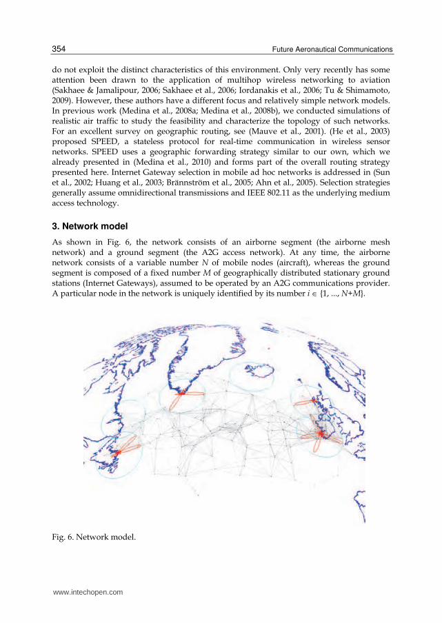
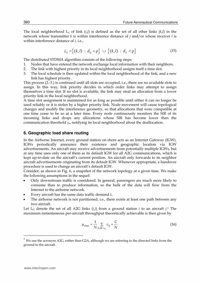
As shown in Fig. 6, the network consists of an airborne segment (the airborne mesh network) and a ground segment (the A2G access network). At any time, the airborne network consists of a variable number N of mobile nodes (aircraft), whereas the ground segment is composed of a fixed number M of geographically distributed stationary ground stations (Internet Gateways), assumed to be operated by an A2G communications provider. A particular node in the network is uniquely identified by its number i {1, ..., N+M}.
Fig. 6. Network model.
www.intechopen.com
The Airborne Internet
355
Direct communication from node i to node j is represented by the directed link (i,j), i≠j. A link (i,j) exists if a sufficiently low bit error rate can be achieved in the absence of multiple access interference. In the absence of interference, the bit error rate depends on the signal-to-noise ratio (SNR) at the receiving end of the link. For simplicity, we assume that all nodes use the same transmit power, high enough for a link to be feasible with any other node within the radio horizon, given by (2)-(3).
3.1 TDMA medium access control All nodes (aircraft and ground stations) are assumed to use half-duplex transceivers on the same carrier frequency (common channel) and are assumed to be synchronized to a common time reference, e.g., by means of GPS. To avoid multiple access interference, link transmissions are scheduled in a TDMA fashion. The time domain is divided into repeating frames of size T time slots, each with a duration Ts long enough to transmit one packet. Transmissions start and end within a slot. The TDMA schedule specifies a link's activation pattern over the frame, that is, during which time slots it can transmit a data packet. The size of a packet corresponds to the duration of a time slot minus the appropriate guard time, required to offset the varying geographic distances between nodes.
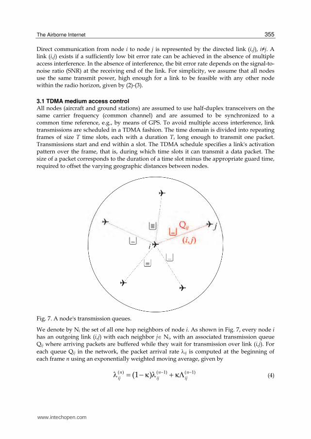
Fig. 7. A node's transmission queues.
We denote by Ni the set of all one hop neighbors of node i. As shown in Fig. 7, every node i has an outgoing link (i,j) with each neighbor jNi, with an associated transmission queue Qij where arriving packets are buffered while they wait for transmission over link (i,j). For
each queue Qij in the network, the packet arrival rate ij is computed at the beginning of each frame n using an exponentially weighted moving average, given by
n n n
ij ij ij
( ) ( 1) ( 1)(1 ) (4)
www.intechopen.com
Future Aeronautical Communications
356
where ( )nij is the number of packet arrivals at Qij during frame n. The moving average is
used to smooth out short-term fluctuations in the arrival rate. The arrival rate ij of each link
(i,j) is used by the traffic sensitive link scheduling algorithm (described in Section 5) to
assign time slots to links proportionally to their traffic demand. Let hij denote the number of time slots currently assigned to link (i,j). The capacity of link (i,j) is given by
c /ij ijh T (5)
where T is the frame length (number of slots). Thus, the capacity of a link is given by the fraction of time slots in the frame that it has been assigned for transmission by the link scheduling algorithm. Note that, in general, cij ≠ cji.
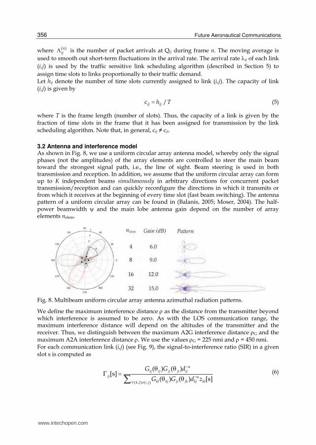
3.2 Antenna and interference model As shown in Fig. 8, we use a uniform circular array antenna model, whereby only the signal phases (not the amplitudes) of the array elements are controlled to steer the main beam toward the strongest signal path, i.e., the line of sight. Beam steering is used in both transmission and reception. In addition, we assume that the uniform circular array can form up to K independent beams simultaneously in arbitrary directions for concurrent packet transmission/reception and can quickly reconfigure the directions in which it transmits or from which it receives at the beginning of every time slot (fast beam switching). The antenna pattern of a uniform circular array can be found in (Balanis, 2005; Moser, 2004). The half-power beamwidth and the main lobe antenna gain depend on the number of array elements nelem.
Fig. 8. Multibeam uniform circular array antenna azimuthal radiation patterns.
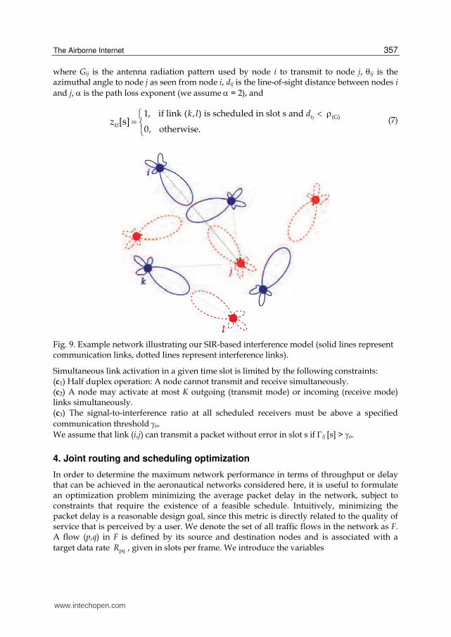
We define the maximum interference distance as the distance from the transmitter beyond which interference is assumed to be zero. As with the LOS communication range, the maximum interference distance will depend on the altitudes of the transmitter and the receiver. Thus, we distinguish between the maximum A2G interference distance G and the maximum A2A interference distance . We use the values G = 225 nmi and = 450 nmi. For each communication link (i,j) (see Fig. 9), the signal-to-interference ratio (SIR) in a given slot s is computed as
( , ) ( , )
( ) ( )[s]
( ) ( ) [s]
ij ij ji ji ij
ij
kl kj ji jk kj klk l i j
G G d
G G d z
(6)
www.intechopen.com
The Airborne Internet
357
where Gij is the antenna radiation pattern used by node i to transmit to node j, ij is the azimuthal angle to node j as seen from node i, dij is the line-of-sight distance between nodes i
and j, is the path loss exponent (we assume = 2), and
(G)1, if link ( , ) is scheduled in slot s and
0, otherwise.[s]
kj
kl
k l dz
(7)
Fig. 9. Example network illustrating our SIR-based interference model (solid lines represent communication links, dotted lines represent interference links).
Simultaneous link activation in a given time slot is limited by the following constraints: (c1) Half duplex operation: A node cannot transmit and receive simultaneously. (c2) A node may activate at most K outgoing (transmit mode) or incoming (receive mode) links simultaneously. (c3) The signal-to-interference ratio at all scheduled receivers must be above a specified
communication threshold o.
We assume that link (i,j) can transmit a packet without error in slot s if ij [s] > o.
4. Joint routing and scheduling optimization
In order to determine the maximum network performance in terms of throughput or delay that can be achieved in the aeronautical networks considered here, it is useful to formulate an optimization problem minimizing the average packet delay in the network, subject to constraints that require the existence of a feasible schedule. Intuitively, minimizing the packet delay is a reasonable design goal, since this metric is directly related to the quality of service that is perceived by a user. We denote the set of all traffic flows in the network as F. A flow (p,q) in F is defined by its source and destination nodes and is associated with a
target data rate pqR , given in slots per frame. We introduce the variables
www.intechopen.com
Future Aeronautical Communications
358
1, if link ( , ) is scheduled in slot s
0, otherwise.[s]ij
i ju (8)
and
,
1, if link ( , ) carries traffic for flow ( , )
0, otherwise.ij pq
i j p ql (9)
The average packet delay on a wireless link can be approximated by the time that the packet must wait until a transmission opportunity for this link, i.e., until a time slot allocated to this link arrives in the schedule (time slot offset), plus the transmission time itself. Assuming that the slots for a link are distributed at uniform intervals in the TDMA frame, the average delay on link (i,j) can be expressed as
s 1
1
2 [s]ij s T
ij
TD T
u
, (10)
and the average packet delay in the network is given by
,
( , ) ( , )( , )
1pq ij pq ij
pq p q F i jp q F
D R l DR
. (11)
Note that the average packet delay depends on both the routing variables ,lij pq and the
scheduling variables [s]iju . When the traffic demand is known, the link delay is a convex
function of the scheduling variables. Unfortunately, the joint routing and scheduling delay
minimization problem is non-convex, so that the global optimum cannot be found in
general. Therefore, we split the problem up into two steps: First, a minimization of the
weighted hop count (mWHC), subject to constraints requiring a feasible schedule; second,
minimization of the average flow delay (mAFD), given the link loads resulting from the
solution of the first step. The problem formulation is summarized in the table below.
The coefficients ijw in the objective function (12a) allow links to be assigned different
weights. For example, a higher weight can be given to satellite links than to A2A links in
order to avoid the high delay and cost that are typically associated with satellites. The first
two routing constraints (12b), (12c) ensure that flows begin at their source and end at their
destination, respectively. The third constraint (12d) ensures that traffic flow is conserved at
intermediate nodes. The last three constraints concern the scheduling. The first (12e) ensures
half duplex operations, the second (12f) enforces that the capacity of each link is sufficient to
carry the link’s traffic load, and the final constraint (12g) ensures that the SIR of all active
links is above the SIR threshold required for error free communication. The mAFD problem
does not require the routing constraints, since the routing has already been decided in Step
1. The constraints are the same as the scheduling constraints for mWHC. Unfortunately, the applicability of this approach is limited to very small networks due to the large number of integer variables. A more efficient, but suboptimal, approach based on
www.intechopen.com

The Airborne Internet
359
Step 1: Weighted Hop Count Minimization
Step 2: Average Flow Delay Minimization
,
( , ) ( , )
minij pq ij pq
i j p q F
w R l
(12a)
,
( , ) ( , )
minij pq ij
p q F i j
l D
(13a)
s.t. , ( , )
pj pq pq
j
l R p q (12b) s.t. [s] [s] 1 , sij ji
i i
u u j (13b)
, ( , )
iq pq pq
i
l R p q (12c) ,
s ( , )
[s] ( , )ij ij pq pq
p q F
u l R i j
(13c)
, ,
ik pq ki pq
i i
l l k (12d) 0[s] [s] ( , ), s
ij iju i j (13d)
[s] [s] 1 , sij ji
i i
u u j (12e)
,
s ( , )
[s] ( , ) ij ij pq pq
p q F
u l R i j
(12f)
0[s] [s] ( , ), s
ij iju i j (12g)
Genetic Algorithms (GAs) has been described in (Hoffmann et al., 2011). In contrast to the mathematical programming approach, the GA does not need to be solved anew with each change in the topology, but can be run “on the fly”, while the network is moving. In addition, the GA can also be successfully applied to non-convex problems, allowing a direct minimization of the average packet delay. In the proposed GA, a random path to a random gateway is selected for each flow when an individual of the initial population is created. The subsequent operations of recombination and mutation may modify the scheduling of links, the routing of a single flow, or exchange entire paths between individuals of the population. In small networks, the GA provides performance results similar to what can be achieved by means of the mWHC/mAFD approach. It has been shown in (Hoffmann et al., 2011) that the GA easily outperforms hop count based routing and gateway selection in larger networks. However, both of these approaches are mainly of interest to determine performance bounds of the network. They require global knowledge of the traffic demands and aircraft positions at a centralized processor. For practical purposes, it is evident that distributed routing and scheduling algorithms are required. These will be addressed in the following.
5. Distributed STDMA link scheduling
In order to assign capacity to links proportionally to their traffic load, we use the traffic
sensitive STDMA link scheduling algorithm proposed in (Grönkvist, 2005). In this section,
we provide a brief summary of the essential aspects of the algorithm. For a detailed
description, see (Grönkvist, 2005).
The priority of a link (i,j) is defined as
/ij ij ijp h (14)
where ij is the packet arrival rate at Qij (in packets/frame) given in (4) and hij is the number
of slots currently assigned to link (i,j). The link priorities are used by the link scheduling
algorithm to provide fairness among links competing for radio resources in the network.
www.intechopen.com
Future Aeronautical Communications
360
The local neighborhood Lij of link (i,j) is defined as the set of all other links (k,l) in the network whose transmitter k is within interference distance of j and/or whose receiver l is within interference distance of i, i.e.,
ij i jkj lk l d k l d( , ) : ( , ) : L (15)
The distributed STDMA algorithm consists of the following steps: 1. Nodes that have entered the network exchange local information with their neighbors. 2. The link with highest priority in its local neighborhood assigns itself a time slot. 3. The local schedule is then updated within the local neighborhood of the link, and a new
link has highest priority. This process (2.-3.) is continued until all slots are occupied, i.e., there are no available slots to assign. In this way, link priority decides in which order links may attempt to assign themselves a time slot. If no slot is available, the link may steal an allocation from a lower priority link in the local neighborhood. A time slot assignment is maintained for as long as possible until either it can no longer be used reliably or it is stolen by a higher priority link. Node movement will cause topological changes and modify the interference geometry, so that allocations that were compatible at one time cease to be so at a later time. Every node continuously monitors the SIR of its incoming links and drops any allocations whose SIR has become lower than the communication threshold o, notifying its local neighborhood about the deallocation.
6. Geographic load share routing
In the Airborne Internet, every ground station on shore acts as an Internet Gateway (IGW). IGWs periodically announce their existence and geographic location via IGW advertisements. An aircraft may receive advertisements from potentially multiple IGWs, but at any time uses only one of them as its default IGW for all A2G communications, which is kept up-to-date on the aircraft’s current position. An aircraft only forwards to its neighbor aircraft advertisements originating from its default IGW. Whenever appropriate, a handover procedure is used to change an aircraft’s default IGW. Consider, as shown in Fig. 6, a snapshot of the network topology at a given time. We make the following assumptions in the sequel:
Only downstream traffic is considered. In general, passengers are much more likely to consume than to produce information, so the bulk of the data will flow from the Internet to the airborne network.
Every aircraft has the same data traffic demand .
The airborne network is not partitioned, i.e., there exists at least one path between any two aircraft.
Let LG denote the set of all A2G links (i,j) from a ground station i to an aircraft j.1 The maximum instantaneous per-aircraft throughput theoretically achievable is then given by
c
G
max ij
1 C
N N L(i, j)
(16)
1 We use the acronym A2G, rather than G2A, although we are referring to the directed links from the
ground to the aircraft.
www.intechopen.com
The Airborne Internet
361
where N is the number of aircraft forming the airborne network, C denotes the total A2G capacity available to the airborne mesh network, and cij is given by (5). In order to fully exploit the total A2G capacity available at any given time, we propose a novel routing scheme, Geographic Load Share Routing (GLSR), to balance the traffic load among all A2G links. GLSR consists of two separate strategies:
a forwarding strategy, enabling every intermediate node to choose the next hop on a packet-by-packet basis using only position and buffer size information local to the forwarding node, and
a handover strategy, enabling the access network to control which aircraft is associated with which IGW at any time, based on geographic proximity and a measure of IGW congestion.
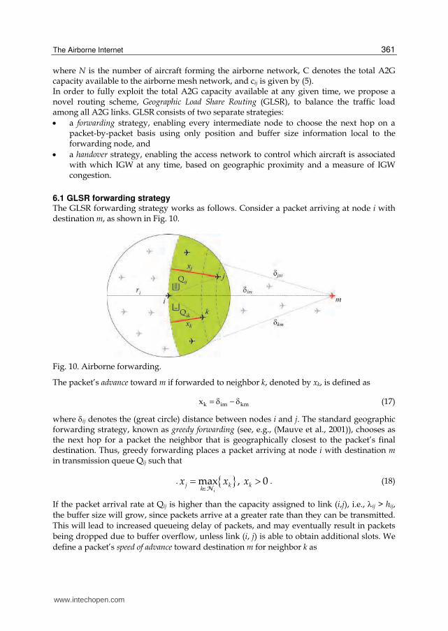
6.1 GLSR forwarding strategy The GLSR forwarding strategy works as follows. Consider a packet arriving at node i with destination m, as shown in Fig. 10.
Fig. 10. Airborne forwarding.
The packet’s advance toward m if forwarded to neighbor k, denoted by xk, is defined as
k im kmx (17)
where ij denotes the (great circle) distance between nodes i and j. The standard geographic forwarding strategy, known as greedy forwarding (see, e.g., (Mauve et al., 2001)), chooses as the next hop for a packet the neighbor that is geographically closest to the packet’s final destination. Thus, greedy forwarding places a packet arriving at node i with destination m in transmission queue Qij such that
. max , 0i
j k kk
x x x N
. (18)
If the packet arrival rate at Qij is higher than the capacity assigned to link (i,j), i.e., ij > hij,
the buffer size will grow, since packets arrive at a greater rate than they can be transmitted.
This will lead to increased queueing delay of packets, and may eventually result in packets
being dropped due to buffer overflow, unless link (i, j) is able to obtain additional slots. We
define a packet’s speed of advance toward destination m for neighbor k as
www.intechopen.com
Future Aeronautical Communications
362
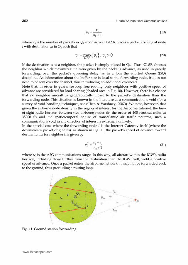
1
kk
k
xv
n (19)
where nk is the number of packets in Qik upon arrival. GLSR places a packet arriving at node i with destination m in Qij such that
max , 0i
j k kk
v v v N
(20)
If the destination m is a neighbor, the packet is simply placed in Qim. Thus, GLSR chooses the neighbor which maximizes the ratio given by the packet’s advance, as used in greedy forwarding, over the packet’s queueing delay, as in a Join the Shortest Queue (JSQ) discipline. As information about the buffer size is local to the forwarding node, it does not need to be sent over the channel, thus introducing no additional overhead. Note that, in order to guarantee loop free routing, only neighbors with positive speed of advance are considered for load sharing (shaded area in Fig. 10). However, there is a chance that no neighbor aircraft is geographically closer to the packet’s destination than the forwarding node. This situation is known in the literature as a communications void (for a survey of void handling techniques, see (Chen & Varshney, 2007)). We note, however, that given the airborne node density in the region of interest for the Airborne Internet, the line-of-sight radio horizon between two airborne nodes (in the order of 400 nautical miles at 35000 ft) and the spatiotemporal nature of transatlantic air traffic patterns, such a communications void in any direction of interest is extremely unlikely. In the special case where the forwarding node i is the Internet Gateway itself (where the downstream packet originates), as shown in Fig. 11, the packet’s speed of advance toward destination m for neighbor k is given by
G G
1k
kk
x rv
n
(21)
where rG is the A2G communications range. In this way, all aircraft within the IGW’s radio horizon, including those further from the destination than the IGW itself, yield a positive speed of advance. Once a packet enters the airborne network, it may not be forwarded back to the ground, thus precluding a routing loop.
Fig. 11. Ground station forwarding.
www.intechopen.com
The Airborne Internet
363
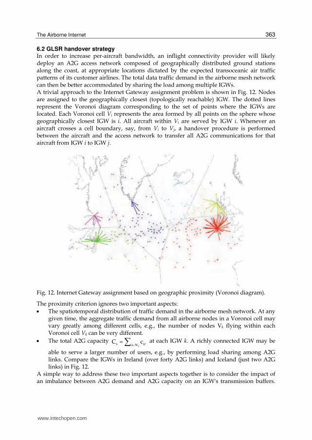
6.2 GLSR handover strategy In order to increase per-aircraft bandwidth, an inflight connectivity provider will likely deploy an A2G access network composed of geographically distributed ground stations along the coast, at appropriate locations dictated by the expected transoceanic air traffic patterns of its customer airlines. The total data traffic demand in the airborne mesh network can then be better accommodated by sharing the load among multiple IGWs. A trivial approach to the Internet Gateway assignment problem is shown in Fig. 12. Nodes are assigned to the geographically closest (topologically reachable) IGW. The dotted lines represent the Voronoi diagram corresponding to the set of points where the IGWs are located. Each Voronoi cell Vi represents the area formed by all points on the sphere whose geographically closest IGW is i. All aircraft within Vi are served by IGW i. Whenever an aircraft crosses a cell boundary, say, from Vi to Vj, a handover procedure is performed between the aircraft and the access network to transfer all A2G communications for that aircraft from IGW i to IGW j.
Fig. 12. Internet Gateway assignment based on geographic proximity (Voronoi diagram).
The proximity criterion ignores two important aspects:
The spatiotemporal distribution of traffic demand in the airborne mesh network. At any given time, the aggregate traffic demand from all airborne nodes in a Voronoi cell may vary greatly among different cells, e.g., the number of nodes Vk flying within each Voronoi cell Vk can be very different.
The total A2G capacity C ck
k kll N
at each IGW k. A richly connected IGW may be
able to serve a larger number of users, e.g., by performing load sharing among A2G links. Compare the IGWs in Ireland (over forty A2G links) and Iceland (just two A2G links) in Fig. 12.
A simple way to address these two important aspects together is to consider the impact of an imbalance between A2G demand and A2G capacity on an IGW's transmission buffers.
www.intechopen.com
Future Aeronautical Communications
364
Consider IGW k and let Qkl denote the average buffer size of transmission buffer Qkl, i.e.,
the average number of packets waiting for transmission over A2G link (k,l). By virtue of the GLSR forwarding strategy described in the previous section, A2G traffic load will be shared among all A2G links at IGW k. In order to characterize quantitatively the ratio of A2G demand to A2G capacity, we define the congestion at IGW k as the maximum average buffer size among all its A2G links, i.e.,
max Qk
klkl N
(22)
The objective is to balance traffic load among IGWs in order to prevent unnecessary congestion at an IGW while other IGWs have free available capacity. This requires a handover management strategy that takes into account not only the geographic coordinates of the airborne nodes, but also the congestion measure at each IGW, as defined in (22). To achieve this, GLSR relies on a centralized Internet Gateway handover manager in the access network, which is assumed to know the current geographic coordinates (m, m) of every airborne node m in the network, as well as the congestion measure k for each IGW k. For every airborne node m, we define its congestion distance to Internet Gateway k as
1km km k (23)
The GLSR handover strategy works as follows. Every h seconds (handover period), the IGW handover manager computes for every aircraft m (currently associated with IGW i) its current congestion distance im
the IGW j at minimum congestion distance, i.e., satisfying
minjm kmk
(24)
Note that, by virtue of (24), we have im jm . If i j m , no handover is required.
Otherwise, the aircraft h with greatest metric ratio, i.e., satisfying
maxih im
mjh jm
(25)
performs a handover from IGW i to IGW j. Thus, GLSR periodically checks whether any airborne node can enjoy a shorter congestion distance to the access network, given the current geographic distribution of the airborne network and the current congestion situation at the access network. If every aircraft is associated with the IGW at minimum congestion distance, no handover is required. Otherwise, the aircraft which can benefit most from a handover (i.e., has the greatest metric ratio, as given in (25)) performs a handover to the IGW at minimum congestion distance.
7. Maximum throughput analysis
Consider the following three routing schemes: [G+V] Greedy forwarding with fixed Voronoi cells. No load sharing takes place. Packets are always forwarded to the next hop that is closest to the final destination. An aircraft chooses as its default IGW the geographically closest one.
www.intechopen.com
The Airborne Internet
365
[S+V] Speed of advance forwarding with fixed Voronoi cells. The speed of advance metric is used to balance load among A2G links at each IGW, but no load sharing is performed among IGWs, i.e., each aircraft is associated with the geographically closest IGW. [S+H] Speed of advance forwarding with cell breathing. Load sharing takes place among A2G links, via the speed of advance metric, and among IGWs, via the congestion distance metric. The maximum per-node throughput with greedy forwarding is given by
G
G+V( , )
cmin
G
ij
i jij
L
(26)
where Gij denotes the number of airborne nodes in Voronoi cell Vi whose traffic is routed via A2G link (i,j). On the other hand, when packets are forwarded according to their speed of advance, all A2G links available at IGW k may be used to route packets to any of the Vk destination aircraft within Voronoi cell Vk. Which specific A2G link is used to transmit a packet will depend on the position of the destination aircraft and the state of the multi-queue system at
the IGW upon arrival. Thus, the total A2G capacity N
C ck
k kll is shared equally by all Vk
aircraft in cell Vk. The maximum per-node throughput is therefore given by
S+V
Cmin
Vk
kk
(27)
The GLSR handover strategy effectively adapts the size of each cell based on the congestion measure at each IGW, giving rise to cell breathing. A cell experiencing congestion will become increasingly unattractive to nodes close to the cell boundary, causing them to perform handovers to neighboring cells with lower congestion. Thus, the cell in question will effectively shrink. As traffic demand increases, the combined effect of both geographic load sharing strategies is such that cells with higher total A2G capacity will swallow nodes from congested cells with lower A2G capacity, until a congestion equilibrium is found among neighboring cells. In saturation, the number of nodes in cell k, denoted by Nk, will be roughly proportional to the total A2G capacity Ck available at IGW k. Thus, the ratio Ck/Nk will be approximately the same for every cell k, and the maximum per-aircraft throughput will approach the theoretical maximum given in (16), as
S+H max
C Cmin k
kkN N
(28)
Thus, through the combination of both strategies we fully exploit the total A2G capacity C
available at any given time to the airborne network via all A2G links.
8. Simulation results
In order to assess the performance of our routing strategy in a realistic aeronautical scenario, we have implemented our network model in the OMNeT++ simulation framework (OMNeT++, 2011). The simulated scenario consists of six Internet Gateways, placed as shown in Fig. 6. We generate air traffic according to the airline flight schedule database
www.intechopen.com
Future Aeronautical Communications
366
published by the International Air Transport Association (IATA), containing the departure and destination airports and schedules of all commercial airlines worldwide in operation today (IATA, 2007). We simulate a 24 hour time window (starting at 1200 UTC) corresponding to an average day (in terms of air traffic volume). Flight trajectories are approximated by great circle arcs between departure and destination airports. We assume a 50% equipage level and thus generate each transatlantic flight with a probability of 0.5. All aircraft are assumed to fly at the same altitude of 35000 ft, resulting in an A2G range rG =
200 nmi. The airborne topology is controlled by every aircraft by applying the distributed
Cone-Based Topology Control (CBTC) algorithm proposed in (Li et al., 2005). For any given
aircraft i, the set of neighbors Ni is formed by all nodes within the minimum range ri, with
ir r rG G2 , such that every cone of 120° contains at least one neighbor aircraft.
Internet traffic is generated at each IGW k based on a Poisson traffic model with mean value
Nk packets/sec, where Nk is the number of aircraft served by IGW k and is the per-aircraft
traffic demand, which is the same for all aircraft. Each new packet’s destination is chosen
randomly among all aircraft in the IGW’s aircraft set.
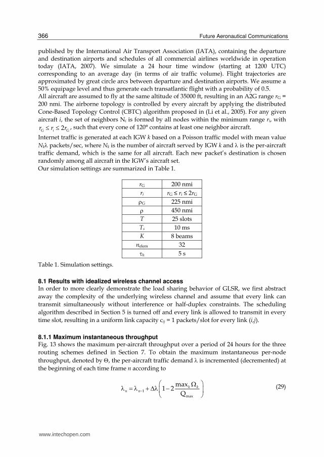
Our simulation settings are summarized in Table 1.
rG 200 nmi
ri rG ≤ ri ≤ 2rG
G 225 nmi
450 nmi
T 25 slots
Ts 10 ms
K 8 beams
nelem 32
h 5 s
Table 1. Simulation settings.
8.1 Results with idealized wireless channel access In order to more clearly demonstrate the load sharing behavior of GLSR, we first abstract
away the complexity of the underlying wireless channel and assume that every link can
transmit simultaneously without interference or half-duplex constraints. The scheduling
algorithm described in Section 5 is turned off and every link is allowed to transmit in every
time slot, resulting in a uniform link capacity cij = 1 packets/slot for every link (i,j).
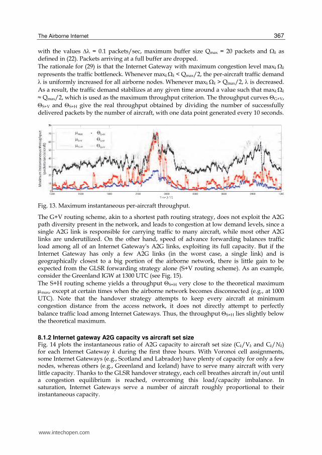
8.1.1 Maximum instantaneous throughput Fig. 13 shows the maximum per-aircraft throughput over a period of 24 hours for the three
routing schemes defined in Section 7. To obtain the maximum instantaneous per-node
throughput, denoted by , the per-aircraft traffic demand is incremented (decremented) at
the beginning of each time frame n according to
1
max
max1 2
Qk k
n n (29)
www.intechopen.com
The Airborne Internet
367
with the values = 0.1 packets/sec, maximum buffer size Qmax = 20 packets and k as defined in (22). Packets arriving at a full buffer are dropped.
The rationale for (29) is that the Internet Gateway with maximum congestion level maxk k
represents the traffic bottleneck. Whenever maxk k < Qmax/2, the per-aircraft traffic demand
is uniformly increased for all airborne nodes. Whenever maxk k > Qmax/2, is decreased.
As a result, the traffic demand stabilizes at any given time around a value such that maxk k
≈ Qmax/2, which is used as the maximum throughput criterion. The throughput curves G+V,
S+V and S+H give the real throughput obtained by dividing the number of successfully delivered packets by the number of aircraft, with one data point generated every 10 seconds.
Fig. 13. Maximum instantaneous per-aircraft throughput.
The G+V routing scheme, akin to a shortest path routing strategy, does not exploit the A2G path diversity present in the network, and leads to congestion at low demand levels, since a single A2G link is responsible for carrying traffic to many aircraft, while most other A2G links are underutilized. On the other hand, speed of advance forwarding balances traffic load among all of an Internet Gateway's A2G links, exploiting its full capacity. But if the Internet Gateway has only a few A2G links (in the worst case, a single link) and is geographically closest to a big portion of the airborne network, there is little gain to be expected from the GLSR forwarding strategy alone (S+V routing scheme). As an example, consider the Greenland IGW at 1300 UTC (see Fig. 15).
The S+H routing scheme yields a throughput S+H very close to the theoretical maximum
max, except at certain times when the airborne network becomes disconnected (e.g., at 1000 UTC). Note that the handover strategy attempts to keep every aircraft at minimum congestion distance from the access network, it does not directly attempt to perfectly
balance traffic load among Internet Gateways. Thus, the throughput S+H lies slightly below the theoretical maximum.
8.1.2 Internet gateway A2G capacity vs aircraft set size Fig. 14 plots the instantaneous ratio of A2G capacity to aircraft set size (Ck/Vk and Ck/Nk) for each Internet Gateway k during the first three hours. With Voronoi cell assignments, some Internet Gateways (e.g., Scotland and Labrador) have plenty of capacity for only a few nodes, whereas others (e.g., Greenland and Iceland) have to serve many aircraft with very little capacity. Thanks to the GLSR handover strategy, each cell breathes aircraft in/out until a congestion equilibrium is reached, overcoming this load/capacity imbalance. In saturation, Internet Gateways serve a number of aircraft roughly proportional to their instantaneous capacity.
www.intechopen.com
Future Aeronautical Communications
368
Fig. 14. Instantaneous ratio of A2G capacity to aircraft set size at each Internet Gateway for Voronoi cell assignments (left) and GLSR (right). For each IGW, the color is as in Fig. 15.
Fig. 15 shows the Internet Gateway assignments at 1300 UTC for the G+V and S+H routing
schemes. As traffic demand increases, the handover strategy appears to deform the Voronoi
diagram by keeping every aircraft at minimum congestion distance from the access network.
The trace of traffic through the network is also shown (below), the width of each link
indicating the volume of traffic flowing through it. GLSR exploits the rich connectivity of
the airborne mesh network, making opportunistic use of the A2G path diversity to avoid
buffer congestion as traffic demand fluctuates.
Fig. 15. Internet Gateway assignments and link usage at 1300 UTC for G+V (left) and S+H (right). Width is proportional to link traffic load.
www.intechopen.com
The Airborne Internet
369
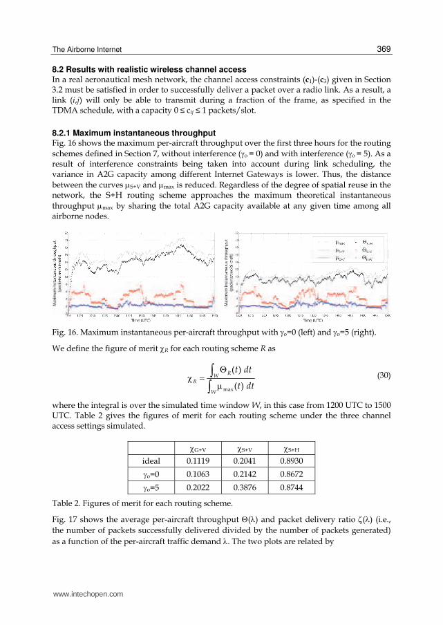
8.2 Results with realistic wireless channel access In a real aeronautical mesh network, the channel access constraints (c1)-(c3) given in Section 3.2 must be satisfied in order to successfully deliver a packet over a radio link. As a result, a link (i,j) will only be able to transmit during a fraction of the frame, as specified in the TDMA schedule, with a capacity 0 ≤ cij ≤ 1 packets/slot.
8.2.1 Maximum instantaneous throughput Fig. 16 shows the maximum per-aircraft throughput over the first three hours for the routing
schemes defined in Section 7, without interference (o = 0) and with interference (o = 5). As a result of interference constraints being taken into account during link scheduling, the variance in A2G capacity among different Internet Gateways is lower. Thus, the distance
between the curves S+V and max is reduced. Regardless of the degree of spatial reuse in the network, the S+H routing scheme approaches the maximum theoretical instantaneous
throughput max by sharing the total A2G capacity available at any given time among all airborne nodes.
Fig. 16. Maximum instantaneous per-aircraft throughput with o=0 (left) and o=5 (right).
We define the figure of merit R for each routing scheme R as
RW
R
W
t dt
t dtmax
( )
( )
(30)
where the integral is over the simulated time window W, in this case from 1200 UTC to 1500 UTC. Table 2 gives the figures of merit for each routing scheme under the three channel access settings simulated.
G+V S+V S+H
ideal 0.1119 0.2041 0.8930
o=0 0.1063 0.2142 0.8672
o=5 0.2022 0.3876 0.8744
Table 2. Figures of merit for each routing scheme.
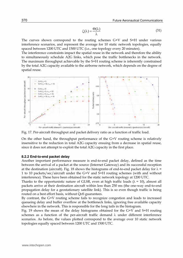
Fig. 17 shows the average per-aircraft throughput () and packet delivery ratio () (i.e.,
the number of packets successfully delivered divided by the number of packets generated)
as a function of the per-aircraft traffic demand . The two plots are related by
www.intechopen.com
Future Aeronautical Communications
370
( )( )
(31)
The curves shown correspond to the routing schemes G+V and S+H under various interference scenarios, and represent the average for 10 static network topologies, equally spaced between 1200 UTC and 1500 UTC (i.e., one topology every 20 minutes). The interference constraints impact the spatial reuse in the network and therefore the ability to simultaneously schedule A2G links, which pose the traffic bottlenecks in the network. The maximum throughput achievable by the S+H routing scheme is inherently constrained by the total A2G capacity available to the airborne network, which depends on the degree of spatial reuse.
Fig. 17. Per-aircraft throughput and packet delivery ratio as a function of traffic load.
On the other hand, the throughput performance of the G+V routing scheme is relatively insensitive to the reduction in total A2G capacity ensuing from a decrease in spatial reuse, since it does not attempt to exploit the total A2G capacity in the first place.
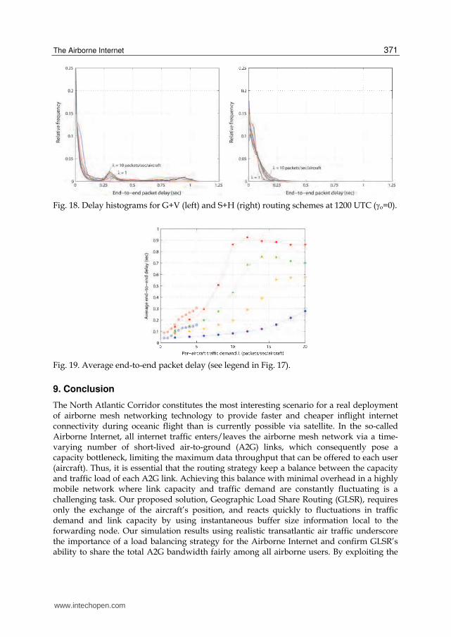
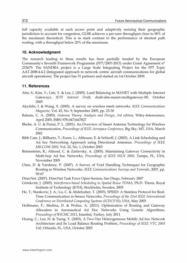
8.2.2 End-to-end packet delay Another important performance measure is end-to-end packet delay, defined as the time between the arrival of a packet at the source (Internet Gateway) and its successful reception at the destination (aircraft). Fig. 18 shows the histograms of end-to-end packet delay for = 1 to 10 packets/sec/aircraft under the G+V and S+H routing schemes (with and without interference). These have been obtained for the static network topology at 1200 UTC. Thanks to the opportunistic nature of GLSR, even at high traffic loads (= 10), almost all packets arrive at their destination aircraft within less than 250 ms (the one-way end-to-end propagation delay for a geostationary satellite link). This is so even though traffic is being routed on a best effort basis, without QoS guarantees. By contrast, the G+V routing scheme fails to recognize congestion and leads to increased queueing delay and buffer overflow at the bottleneck links, ignoring free available capacity elsewhere in the network. This is responsible for the long tails in the histogram. Fig. 19 shows the mean of the delay histograms obtained for the G+V and S+H routing
schemes as a function of the per-aircraft traffic demand under different interference scenarios. As before, the values plotted correspond to the average over 10 static network topologies equally spaced between 1200 UTC and 1500 UTC.
www.intechopen.com
The Airborne Internet
371
Fig. 18. Delay histograms for G+V (left) and S+H (right) routing schemes at 1200 UTC (o=0).
Fig. 19. Average end-to-end packet delay (see legend in Fig. 17).
9. Conclusion
The North Atlantic Corridor constitutes the most interesting scenario for a real deployment of airborne mesh networking technology to provide faster and cheaper inflight internet connectivity during oceanic flight than is currently possible via satellite. In the so-called Airborne Internet, all internet traffic enters/leaves the airborne mesh network via a time-varying number of short-lived air-to-ground (A2G) links, which consequently pose a capacity bottleneck, limiting the maximum data throughput that can be offered to each user (aircraft). Thus, it is essential that the routing strategy keep a balance between the capacity and traffic load of each A2G link. Achieving this balance with minimal overhead in a highly mobile network where link capacity and traffic demand are constantly fluctuating is a challenging task. Our proposed solution, Geographic Load Share Routing (GLSR), requires only the exchange of the aircraft’s position, and reacts quickly to fluctuations in traffic demand and link capacity by using instantaneous buffer size information local to the forwarding node. Our simulation results using realistic transatlantic air traffic underscore the importance of a load balancing strategy for the Airborne Internet and confirm GLSR’s ability to share the total A2G bandwidth fairly among all airborne users. By exploiting the
www.intechopen.com
Future Aeronautical Communications
372
full capacity available at each access point and adaptively resizing their geographic jurisdiction to account for congestion, GLSR achieves a per-user throughput close to 90% of the maximum theoretical. This is in stark contrast to the performance of shortest path routing, with a throughput below 20% of the maximum.
10. Acknowledgment
The research leading to these results has been partially funded by the European Community's Seventh Framework Programme (FP7/2007-2013) under Grant Agreement n° 233679. The SANDRA project is a Large Scale Integrating Project for the FP7 Topic AAT.2008.4.4.2 (Integrated approach to network centric aircraft communications for global aircraft operations). The project has 31 partners and started on 1st October 2009.
11. References
Ahn, S.; Kim, Y.; Lim, Y. & Lee, J. (2005). Load Balancing in MANET with Multiple Internet
Gateways, IETF Internet Draft, draft-ahn-manet-multigateway-00, October
2005
Akyildiz, I. & Wang, X. (2005). A survey on wireless mesh networks. IEEE Communications
Magazine, Vol. 43, No. 9, September 2005, pp. 23-30
Balanis, C. A. (2005). Antenna Theory: Analysis and Design, 3rd edition, Wiley-Interscience,
April 2005, ISBN 978-0471667827
Bhobe, A. U. & Perini, P. L. (2001). An Overview of Smart Antenna Technology for Wireless
Communication, Proceedings of IEEE Aerospace Conference, Big Sky, MT, USA, March
2001
Bibb Cain, J.; Billhartz, T.; Foore, L.; Althouse, E. & Schlorff, J. (2003). A Link Scheduling and
Ad hoc Networking Approach using Directional Antennas. Proceedings of IEEE
MILCOM 2003, Vol. 22, No. 1, October 2003
Brännström, R.; Ahlund, C. & Zaslavsky, A. (2005). Maintaining Gateway Connectivity in
Multi-hop Ad hoc Networks, Proceedings of IEEE WLN 2005, Tampa, FL, USA,
November 2005
Chen, D. & Varshney, P. (2007). A Survey of Void Handling Techniques for Geographic
Routing in Wireless Networks. IEEE Communications Surveys and Tutorials, 2007, pp.
50-67
DirecNet. (2007). DirecNet Task Force Open Session, San Diego, February 2007
Grönkvist, J. (2005). Interference-based Scheduling in Spatial Reuse TDMA, Ph.D. Thesis, Royal
Institute of Technology (KTH), Stockholm, Sweden, 2005
He, T.; Stankovic, J. A.; Lu, C. & Abdelzaher, T. (2003). SPEED: A Stateless Protocol for Real-
Time Communication in Sensor Networks, Proceedings of the 23rd IEEE International
Conference on Distributed Computing Systems (ICDCS’03), USA, May 2003
Hoffmann, F.; Medina, D. & Wolisz, A. (2011). Optimization of Routing and Gateway
Allocation in Aeronautical Ad Hoc Networks Using Genetic Algorithms,
Proceedings of IWCMC 2011, Istanbul, Turkey, July 2011
Huang, C.; Lee, H. & Tseng, Y. (2003). A Two-Tier Heterogeneous Mobile Ad hoc Network
Architecture and Its Load Balance Routing Problem, Proceedings of IEEE VTC 2003
Fall, Orlando, FL, USA, October 2003
www.intechopen.com
The Airborne Internet
373
International Air Transport Association. (2007). IATA Schedule Reference Service (SRS).
Available from: http://www.iata.org/ps/publications/srs/
International Civil Aviation Organization (ICAO). (2008). North Atlantic Minimum Navigation
Performance Specifications (MNPS) Airspace Operations Manual, Edition 2008,
published on behalf of the North Atlantic Systems Planning Group (NAT SPG) by
the European and North Atlantic Office of ICAO, August 2008
International Telecommunications Union. (1986). Recommendation ITU-R P. 528-2,
Propagation Curves for Aeronautical Mobile and Radionavigation Services using the VHF,
UHF and SHF bands, ITU, Geneva, Switzerland, 1986
Iordanakis, M.; Yannis, D.; Karras, K.; Bogdos, G.; Dilintas, G.; Amirfeiz, M.; Colangelo, G. &
Baiotti, S. (2006). Ad-hoc Routing Protocol for Aeronautical Mobile Ad-Hoc
Networks, Proceedings of 5th International Symposium on Communication Systems,
Networks and Digital Signal Processing (CSNDSP), July 2006
Li, L.; Halpern, J. Y.; Bahl, P.; Wang, Y-M. & Wattenhofer, R. (2005). A Cone-Based
Distributed Topology-Control Algorithm for Wireless Multi-Hop Networks.
IEEE/ACM Transactions on Networking, Vol. 13, No. 1, February 2005, pp. 147-
159
Mauve, M.; Widmer, J. & Hartenstein, H. (2001). A Survey on Position-based Routing in
Mobile Ad Hoc Networks. IEEE Network, Vol. 15, No. 6, November 2001, pp.
30-39
McNary, W. (2007). Transformational Aircraft Communication Using a Broadband Mesh
Network, Proceedings of 7th ICNS Conference, May 2007
Medina, D.; Hoffmann, F.; Ayaz, S. & Rokitansky, C.-H. (2008a). Feasibility of an
Aeronautical Mobile Ad Hoc Network Over the North Atlantic Corridor,
Proceedings of IEEE SECON 2008, San Francisco, CA, USA, June 2008
Medina, D.; Hoffmann, F.; Ayaz, S. & Rokitansky, C.-H. (2008b). Topology Characterization
of High Density Airspace Aeronautical Ad Hoc Networks, Proceedings of IEEE
MASS 2008, Atlanta, GA, USA, September 2008
Medina, D.; Hoffmann, F.; Rossetto, F. & Rokitansky, C.-H. (2010). A Crosslayer Geographic
Routing Algorithm for the Airborne Internet, Proceedings of IEEE ICC 2010, Cape
Town, South Africa, May 2010
Moser, C. (2004). Ad Hoc Networking with Beamforming Antennas: Modeling, Visualization and
Connectivity, Diploma Thesis, Technical University of Munich (TUM), Munich,
Germany, December 2004
Nelson, R. & Kleinrock, L. (1985). Spatial TDMA: A Collision-Free Multihop Channel Access
Protocol. IEEE Transactions on Communications, Vol. 33, No. 9, September 1985, pp.
934-944
OMNeT++. (2011). Available from: http://www.omnetpp.org
Sakhaee, E. & Jamalipour, A. (2006). The Global In-Flight Internet. IEEE Journal on Selected
Areas in Communications, September 2006
Sakhaee, E. ; Jamalipour, A. & Kato, N. (2006). Aeronautical Ad Hoc Networks, Proceedings of IEEE WCNC 2006
www.intechopen.com
Future Aeronautical Communications
374
Sun, Y.; Belding-Royer, E. M. & Perkins, C. E. (2002). Internet Connectivity for Ad Hoc
Mobile Networks. International Journal of Wireless Information Networks, Vol. 9, No. 2,
April 2002
Tu, H. D. & Shimamoto, S. (2009). Mobile Ad-Hoc Network Based Relaying Data System for
Oceanic Flight Routes in Aeronautical Communications. International Journal of
Computer Networks and Communications (IJCNC), Vol. 1, No. 1, April 2009
www.intechopen.com

Future Aeronautical CommunicationsEdited by Dr. Simon Plass
ISBN 978-953-307-625-6Hard cover, 378 pagesPublisher InTechPublished online 26, September, 2011Published in print edition September, 2011
InTech EuropeUniversity Campus STeP Ri Slavka Krautzeka 83/A 51000 Rijeka, Croatia Phone: +385 (51) 770 447 Fax: +385 (51) 686 166www.intechopen.com
InTech ChinaUnit 405, Office Block, Hotel Equatorial Shanghai No.65, Yan An Road (West), Shanghai, 200040, China
Phone: +86-21-62489820 Fax: +86-21-62489821
There are well-founded concerns that current air transportation systems will not be able to cope with theirexpected growth. Current processes, procedures and technologies in aeronautical communications do notprovide the flexibility needed to meet the growing demands. Aeronautical communications is seen as a majorbottleneck stressing capacity limits in air transportation. Ongoing research projects are developing thefundamental methods, concepts and technologies for future aeronautical communications that are required toenable higher capacities in air transportation. The aim of this book is to edit the ensemble of newestcontributions and research results in the field of future aeronautical communications. The book gives thereaders the opportunity to deepen and broaden their knowledge of this field. Today’s and tomorrow’sproblems / methods in the field of aeronautical communications are treated: current trends are identified; IPv6aeronautical network aspect are covered; challenges for the satellite component are illustrated; AeroMACSand LDACS as future data links are investigated and visions for aeronautical communications are formulated.
How to referenceIn order to correctly reference this scholarly work, feel free to copy and paste the following:
Daniel Medina and Felix Hoffmann (2011). The Airborne Internet, Future Aeronautical Communications, Dr.Simon Plass (Ed.), ISBN: 978-953-307-625-6, InTech, Available from:http://www.intechopen.com/books/future-aeronautical-communications/the-airborne-internet

© 2011 The Author(s). Licensee IntechOpen. This chapter is distributedunder the terms of the Creative Commons Attribution-NonCommercial-ShareAlike-3.0 License, which permits use, distribution and reproduction fornon-commercial purposes, provided the original is properly cited andderivative works building on this content are distributed under the samelicense.