the analytical model of distributed interrupt mechanism in...
TRANSCRIPT

The Analytical Model of Distributed
Interrupt Mechanism in SpaceWire
Network
Liudmila Koblyakova
Saint-Petersburg University of Aerospace Instrumentation
Saint-Petersburg, Russia
2014
15th Conference of Open Innovations Association FRUCT
St. Petersburg, Russia
21-25 April 2014
Introduction
According to consolidated set of requirements for SpaceWire-RT
from European and Russian industry the important task for onboard
distributed real-time systems is single signals transmission with
acknowledge to inform devices about system critical events in real-
time, such as equipment failure or readiness to some action.
For this purpose, the distributed interrupt mechanism is included to
the second edition of SpaceWire standard.
Standard SpaceWire for onboard communication networks
integrates the data and control information transmission.
Hard real-time signalling imposes strict signal delivery constraints and
requires high reliability of signal delivery, so the strict proof of the
distributed interrupt mechanism properties is also important task.
2

Distributed interrupt mechanism
0
000
000
00
0
0
1
0 1
000
000
00
0
0
1
0 1
000
011
01
0
0
1
1 1
111
111
11
0
0
1
1
1
111
111
11
1
0
1
1 1
011
111
11
1
0
1
1 1
001
001
11
0
0
1
1 0
000
000
00
0
0
1
1
Source Node
Handler Node
Nodes are Interrupt code sources and handlers
Nodes and routers contain 32-bit Interrupt Source Register (ISR)
Router: checks the corresponding bit in the ISR: If the bit is '0' it sets the ISR bit
to '1' and the signal propagates to all other router output ports. If the
corresponding bit in the ISR is equal to '1' the Interrupt code will be ignored
Node: A subsequent Interrupt code with the same interrupt source identifier can be
sent by the link only after receipt of an corresponding Acknowledge
3
Network model description
Designation Description
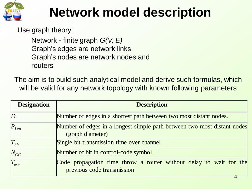
D Number of edges in a shortest path between two most distant nodes.
PLen Number of edges in a longest simple path between two most distant nodes
(graph diameter)
Tbit Single bit transmission time over channel
NCC Number of bit in control-code symbol
Twtc Code propagation time throw a router without delay to wait for the
previous code transmission
Network - finite graph G(V, E)
Graph’s edges are network links
Graph’s nodes are network nodes and
routers
Use graph theory:
The aim is to build such analytical model and derive such formulas, which
will be valid for any network topology with known following parameters
4
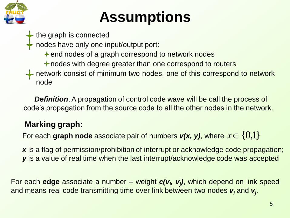
Assumptions the graph is connected
nodes have only one input/output port:
end nodes of a graph correspond to network nodes
nodes with degree greater than one correspond to routers
network consist of minimum two nodes, one of this correspond to network
node
Definition. A propagation of control code wave will be call the process of
code’s propagation from the source code to all the other nodes in the network.
Marking graph:
For each graph node associate pair of numbers v(x, y), where }1,0{х
x is a flag of permission/prohibition of interrupt or acknowledge code propagation;
y is a value of real time when the last interrupt/acknowledge code was accepted
For each edge associate a number – weight с(vi, vj), which depend on link speed
and means real code transmitting time over link between two nodes vi and vj.
5
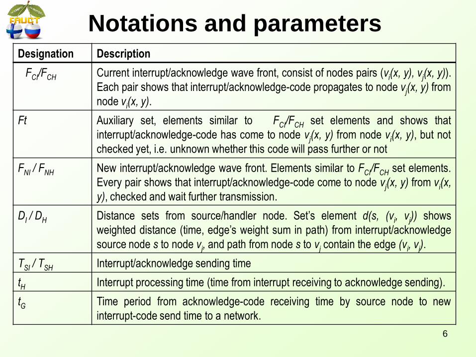
Notations and parameters Designation Description
FCI/FCH Current interrupt/acknowledge wave front, consist of nodes pairs (vi(x, y), vj(x, y)).
Each pair shows that interrupt/acknowledge-code propagates to node vj(x, y) from
node vi(x, y).
Ft Auxiliary set, elements similar to FCI/FCH set elements and shows that
interrupt/acknowledge-code has come to node vj(x, y) from node vi(x, y), but not
checked yet, i.e. unknown whether this code will pass further or not
FNI / FNH New interrupt/acknowledge wave front. Elements similar to FCI/FCH set elements.
Every pair shows that interrupt/acknowledge-code come to node vj(x, y) from vi(x,
y), checked and wait further transmission.
DI / DH Distance sets from source/handler node. Set’s element d(s, (vi, vj)) shows
weighted distance (time, edge’s weight sum in path) from interrupt/acknowledge
source node s to node vj, and path from node s to vj contain the edge (vi, vj).
TSI / TSH Interrupt/acknowledge sending time
tH Interrupt processing time (time from interrupt receiving to acknowledge sending).
tG Time period from acknowledge-code receiving time by source node to new
interrupt-code send time to a network.
6

Algorithm
7

Example
8

Proofs Algorithm correctness. Prove that:
interrupt/acknowledge wave propagation time is finitely,
interrupt/acknowledge code wave propagates to all graph nodes
Acknowledge wave to the interrupt does not cross with the interrupt wave in
time, if time of interrupt processing tH will be more than maximum interrupt
processing time.
The next interrupt wave does not cross with wave of acknowledge codes to
previous interrupt, if time interval between acknowledge received and next
interrupt generated tg will be more than maximum acknowledge code wave
propagation time.
Proposition about interrupt and acknowledge wave cross
Interrupt (acknowledge) code from the source node vs (handler node vh) to
all other network nodes propagates by the shortest path and forms the
oriented covering tree.
Consequence of the algorithm
9

Looping problem (1)
10
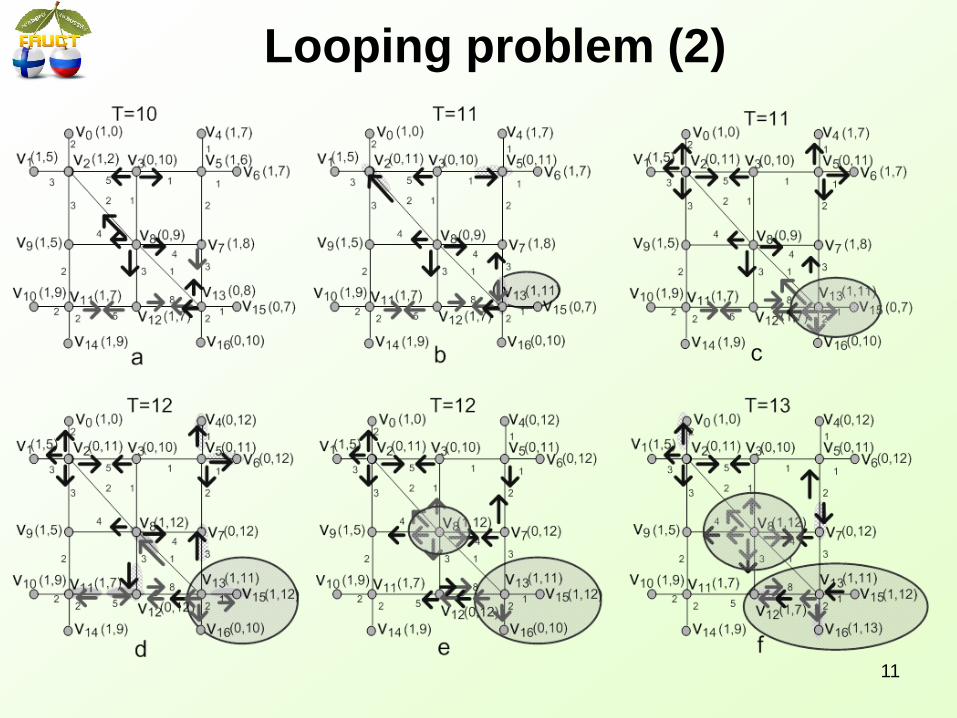
Looping problem (2)
11
Solving of looping problem
For protection from interrupt and acknowledge wave crossing, we offer
to do restriction to minimally possible time interval TISRchange between
every ISR’s bit changes of every router:
The ISR’s bit value could not be changed earlier than time
TISRchange has elapsed.
It is guarantee that if a network router receives the unexpected
interrupt or acknowledge code that it will be not propagate further and
will not cause the looping problem.
The time TISRchange is a system parameter, which should be chosen
more than maximally possible propagation time of interrupt and
acknowledge codes waves.
12
Conclusion
In the paper analytical model for distributed interrupt mechanism is
considered.
The correctness of algorithm work and the algorithm properties are
proved.
Based on this model in other papers the distributed interrupt time
characteristics are derived.
The model allow to derive equations which fit to any networks
topology with known parameters:
D and PLen, they define the number of edges in the shortest an
longest path between two most distanced nodes
Tbit, NC , Twt - network time parameters
So, this paper in couple with the other papers gives to users all
necessary information for using of Distributed Interrupt mechanism in
SpaceWire onboard networks.
13

Thank you!
14