the application of actively tensioned membranes as ... · the application of actively tensioned...
TRANSCRIPT
The application of actively tensioned membranes as formwork for complex curvatures in concrete structures
S. Belton University of Florida School of Architecture, USA
Abstract
While digital tools have opened the floodgates to the exploration and definition of complex geometries in many design fields in the last two decades, their utilization in architecture has been limited depending on the material and fabrication method. Specifically with concrete, complex curvatures have been realized with great difficulty due to the tremendous expense of customized formwork methods utilized, thereby precluding its use from all but the most expensive of constructions. This research explores, demonstrates, and documents a process – as proof of concept from inception to scaled fabrication – of an economic, efficient, and rapid method for designing and constructing complex curvatures in structures of in-situ concrete using digital design, analysis, and fabrication tools. The work builds upon the rich history of concrete fabric forming, both as a method of formal exploration, and of construction efficiency. The present research seeks to combine these two lines of exploration and demonstrate the formal possibilities for medium and even large-scale structures. Specifically, the work introduces the use of actively-tensioned membranes into the vocabulary of fabric formwork and explores its’ practical and formal potential. The use of active-tensioning for concrete formwork foregrounds the geometry of minimal (i.e. anticlastic) surfaces as a territory of exploration for formal expression. Rather than the outright invention of new construction technologies, the research leverages unrealized potential in established fabrication and construction methods, and opens the door to the mass-customization of complex geometries in concrete. The formwork process results in a fully-integrated load-bearing envelope performing thermal and waterproofing functions, thereby reducing construction time and minimizing construction waste. The work seeks
High Performance Structure and Materials VI 27
www.witpress.com, ISSN 1743-3509 (on-line) WIT Transactions on The Built Environment, Vol 124, © 201 WIT Press2
doi:10.2495/HPSM120031

to propose how the craft and expression of architectural form may keep pace with the unending demand for increased efficiency and decreased cost of construction. Keywords: concrete, formwork, minimal surface, material efficiency, anticlastic geometry.
1 Introduction
The present research leverages recent digital modelling and analysis capabilities in combining the techniques of two construction technology lineages – concrete fabric forming utilizing the monolithic dome process, and tensile membrane structures. The combination of these two technologies opens the door to new constructive logics, and an expanded vocabulary of formal typologies for forming concrete with fabric membranes, while streamlining the construction process in terms of both labor and material. The research is conducted through the complete design and fabrication process of a scaled mock-up, as well as extended design speculation of the process.
2 Background
2.1 Dome technology
Monolithic dome technology is a process of fabric-formed concrete developed by David South, Barry South, and Randy South [1]. The process involves inflating fabric membranes into spherical, dome or cylindrical shapes, and applying successive layers of sprayed foam insulation, steel reinforcing, and projected concrete (Fig. 1). The resulting construction is a thin shell concrete structure capable of spans as large as 90 meters or more [2]. Despite the name given to the process, the interest for the present research herein documented lies not in the principle of inflated formwork itself, but in the perfection of an application process for steel reinforcing and concrete that is highly efficient in time and construction staging. Because the formwork is single-sided, application and installation of all elements is greatly simplified, much in the manner that a concrete slab is much easier and faster to prepare and pour than an equivalently sized wall in-situ using standard industry techniques. The monolithic dome process matches the material efficiency endemic to forming concrete using fabric membranes with an application process that is streamlined and economical.
Figure 1: Construction stages of monolithic dome process.
1. inflation 2. spray-on foam 3. reinforcing steel+ shotcrete
28 High Performance Structure and Materials VI
www.witpress.com, ISSN 1743-3509 (on-line) WIT Transactions on The Built Environment, Vol 124, © 201 WIT Press2

Since being patented in 1979, the process has been successfully disseminated and commercialized throughout the world to construct both architectural and storage facilities. However despite its success due to its low-cost and construction speed, the reliance on pneumatic pre-stressing confines the vocabulary of possible forms to largely synclastic curvatures – domes, spheres, and cylinders.
2.2 Tensile membrane structures
The observation that it is the process of projecting and installing materials to single-sided formwork rather than pneumatic pre-stressing of the membrane that is the true advantage of the monolithic dome process leads to the question of whether an alternative means of membrane pre-stressing is possible, one that provides an expanded vocabulary of architectural form-making. In fact there is: mechanical pre-stressing – active tensioning of the membrane at its boundaries. Active tensioning requires a temporary armature to define the restraint boundaries – both fixed and cabled – at the required tension until the concrete has been applied and cured. Yet while the erection of a temporary armature incurs some additional cost and time over pneumatic tensioning, the advantage of mechanical pre-stressing as a method of defining fabric formwork is the greatly expanded vocabulary of forms made possible by the inclusion of anticlastic shapes – i.e., surfaces with negative Gaussian curvature. Spheres, domes, and cylinders are suddenly not the only design choices possible. Yet neither is just any shape possible; rather, in order for the surface to be in equilibrium without any out-of-plane forces, the opposing curvatures must cancel out so as to produce a mean curvature of zero – by definition a minimal surface. The design process then becomes in part a study of possible forms and the varied character of space each describes. As with the monolithic dome process, the technology and application have a long tradition and proven application at large scale with seminal work from Frei Otto, Jörg Schlaich, Edmund Happold, and others. More recent projects such as the installation Marsyas show the potential for even temporary tensioned membranes to span large distances (Fig. 2). The PVC membrane for this project spanned a total length of 140m and surface area of 3500m2, and was tensioned by only 3 steel hollow cylinder rings producing a maximum membrane tension of 1.5 tonnes/m [3]. Such scale and complexity for even temporary applications is due in large part to the advancement in digital modeling and analysis in the last decade. Physical models using soap films and tensioned materials at scale have given way to digital 3d modeling using advanced form-finding software. An interesting characteristic of the use of mechanically pre-stressed fabric as formwork for concrete is the structural inversion of a tensioned membrane to largely compressive shell structure. Such an inversion recalls the suspended catenary models utilized by Gaudi to model the ideal arched structure for the Colònia Güell Chapel. The inversion, of course is less pure than Gaudi’s application as the actively tensioned membrane is not strictly modeling gravity in reverse as the catenary does when turned upside-down, and therefore incurs some out of plane forces depending on the specific form.
High Performance Structure and Materials VI 29
www.witpress.com, ISSN 1743-3509 (on-line) WIT Transactions on The Built Environment, Vol 124, © 201 WIT Press2

Figure 2: Anish Kapoor, “Marsyas” – installation at the Tate Modern gallery, 2002. The total span of the tensioned membrane was 140m. Photo © Suzanne Kelly.
3 Minimal surface – bow tie column
As an example of the potential of tensioned structures, a shape was sought that expresses a synthetic architectural language – in this case combining structure, aperture, and surface/enclosure – endemic to the forms of minimal surfaces. The design developed is a column/skylight in the form of a bow tie (Fig. 3). Topologically, the design is a Mobius Strip since the form has only one side. The design also highlights the two types of constraints utilized in tensioned membrane structures – fixed and cabled – and the dynamic between the two in the development of the form.
Figure 3: Digital model of bowtie column showing tension constraints.
A reference for the design was Frei Otto’s seminal work in tensioned membranes, specifically the Teardrop column [4] for its hybrid quality. It is notable that, while having been planned to be constructed of concrete using conventional formwork techniques, early models were made using soap bubbles and stretch fabric to describe a minimal surface.
fixed constraint
cable constraint
30 High Performance Structure and Materials VI
www.witpress.com, ISSN 1743-3509 (on-line) WIT Transactions on The Built Environment, Vol 124, © 201 WIT Press2
Despite the specific example for this research, an endless variety of forms are possible as design solutions, beyond what is traditionally conceived of for tensile membrane structures. Mathematical theory and art [5] have provided rich explorations into the formal exploration of minimal surfaces, and recent advances in digital modelling and computation have made possible the calculation and engineering of even large-scale mechanically tensioned membrane structures [6].
4 Process
4.1 Digital modelling
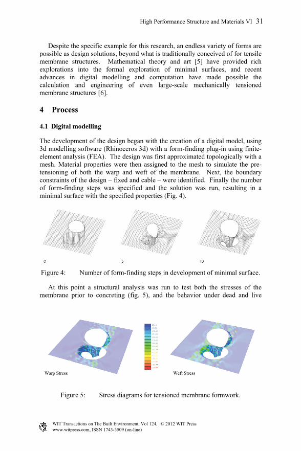
The development of the design began with the creation of a digital model, using 3d modelling software (Rhinoceros 3d) with a form-finding plug-in using finite-element analysis (FEA). The design was first approximated topologically with a mesh. Material properties were then assigned to the mesh to simulate the pre-tensioning of both the warp and weft of the membrane. Next, the boundary constraints of the design – fixed and cable – were identified. Finally the number of form-finding steps was specified and the solution was run, resulting in a minimal surface with the specified properties (Fig. 4).
Figure 4: Number of form-finding steps in development of minimal surface.
At this point a structural analysis was run to test both the stresses of the membrane prior to concreting (fig. 5), and the behavior under dead and live
Figure 5: Stress diagrams for tensioned membrane formwork.
warp stress weft stressWarp Stress Weft Stress
High Performance Structure and Materials VI 31
www.witpress.com, ISSN 1743-3509 (on-line) WIT Transactions on The Built Environment, Vol 124, © 201 WIT Press2
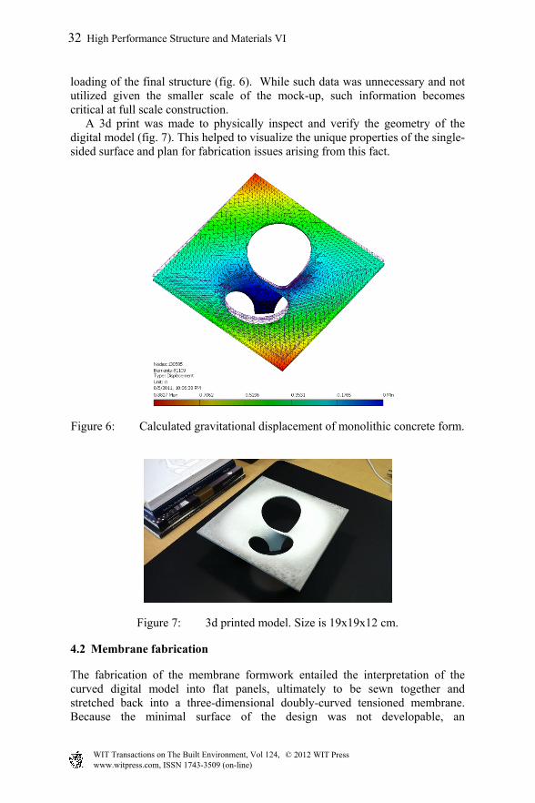
loading of the final structure (fig. 6). While such data was unnecessary and not utilized given the smaller scale of the mock-up, such information becomes critical at full scale construction. A 3d print was made to physically inspect and verify the geometry of the digital model (fig. 7). This helped to visualize the unique properties of the single-sided surface and plan for fabrication issues arising from this fact.
Figure 6: Calculated gravitational displacement of monolithic concrete form.
Figure 7: 3d printed model. Size is 19x19x12 cm.
4.2 Membrane fabrication
The fabrication of the membrane formwork entailed the interpretation of the curved digital model into flat panels, ultimately to be sewn together and stretched back into a three-dimensional doubly-curved tensioned membrane. Because the minimal surface of the design was not developable, an
32 High Performance Structure and Materials VI
www.witpress.com, ISSN 1743-3509 (on-line) WIT Transactions on The Built Environment, Vol 124, © 201 WIT Press2
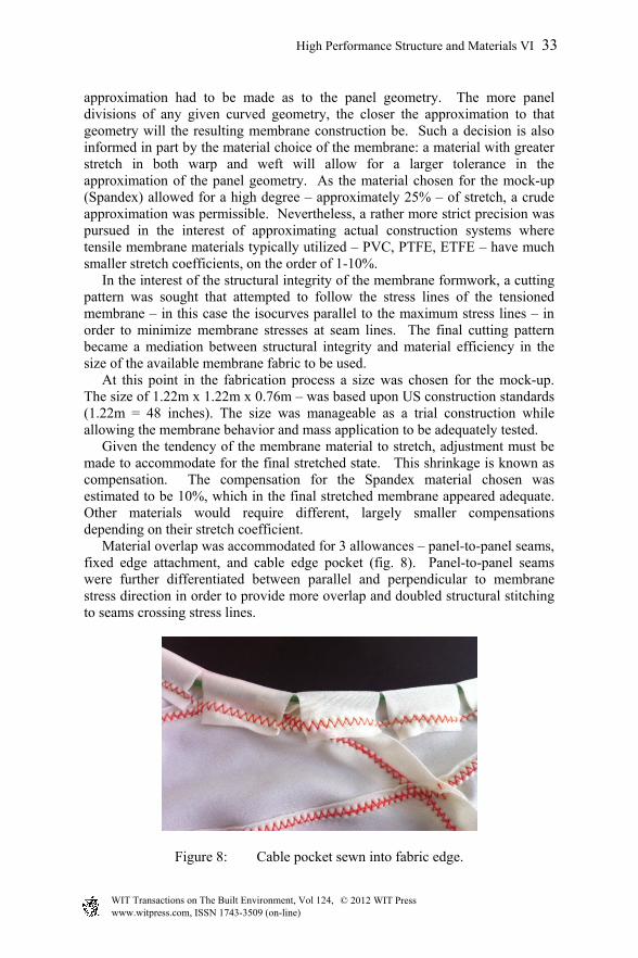
approximation had to be made as to the panel geometry. The more panel divisions of any given curved geometry, the closer the approximation to that geometry will the resulting membrane construction be. Such a decision is also informed in part by the material choice of the membrane: a material with greater stretch in both warp and weft will allow for a larger tolerance in the approximation of the panel geometry. As the material chosen for the mock-up (Spandex) allowed for a high degree – approximately 25% – of stretch, a crude approximation was permissible. Nevertheless, a rather more strict precision was pursued in the interest of approximating actual construction systems where tensile membrane materials typically utilized – PVC, PTFE, ETFE – have much smaller stretch coefficients, on the order of 1-10%. In the interest of the structural integrity of the membrane formwork, a cutting pattern was sought that attempted to follow the stress lines of the tensioned membrane – in this case the isocurves parallel to the maximum stress lines – in order to minimize membrane stresses at seam lines. The final cutting pattern became a mediation between structural integrity and material efficiency in the size of the available membrane fabric to be used. At this point in the fabrication process a size was chosen for the mock-up. The size of 1.22m x 1.22m x 0.76m – was based upon US construction standards (1.22m = 48 inches). The size was manageable as a trial construction while allowing the membrane behavior and mass application to be adequately tested. Given the tendency of the membrane material to stretch, adjustment must be made to accommodate for the final stretched state. This shrinkage is known as compensation. The compensation for the Spandex material chosen was estimated to be 10%, which in the final stretched membrane appeared adequate. Other materials would require different, largely smaller compensations depending on their stretch coefficient. Material overlap was accommodated for 3 allowances – panel-to-panel seams, fixed edge attachment, and cable edge pocket (fig. 8). Panel-to-panel seams were further differentiated between parallel and perpendicular to membrane stress direction in order to provide more overlap and doubled structural stitching to seams crossing stress lines.
Figure 8: Cable pocket sewn into fabric edge.
High Performance Structure and Materials VI 33
www.witpress.com, ISSN 1743-3509 (on-line) WIT Transactions on The Built Environment, Vol 124, © 201 WIT Press2

A final panelling division was developed defining 36 panels, with panel subdivision increasing in areas of greater curvature (fig. 9). This resulted in a formwork with a high degree of accuracy and fidelity to the digital model. The fabric was cut and sewn by hand following templates defined and printed from the digital model (fig. 10). A zigzag stitch was used throughout to maintain the stretch properties of the overall membrane. While digital cutting of the panels from the fabric was both available and rather straightforward through the use of laser cutters, it was ultimately deemed more time-consuming than analog methods, although this remains a potential option should the scale and logistics of a project necessitate. Sometimes things are just easier by hand.
Figure 9: Cutting pattern of 18 panel shapes (x2).
Figure 10: Membrane of sewn panels ready for mounting on tension frame.
4.3 Membrane tensioning mass application
A platform and temporary steel scaffolding was constructed on which to mount the membrane, maintaining both fixed and cable constraints (fig. 11). An interesting conversion between formwork and finished form occurred with the edges of the bowtie column. Both fixed and cable boundaries needed to perform the function of tensioning armature for the membrane, as well as edge to the finished concrete. As such they needed to be conceived not only for their functional performance, but also for their tectonic reading. In the case of the fixed constraint this was a square frame of 20x20mm aluminium T-section
12
13 14
15
18
16 17
9
1234567810
11
14
5
15
16
17
4
2
1
78
6
131211
10
9
3
18
14
5
15
16
17
4
2
1
7
8
6
1312
11
10
9
3
18
and
34 High Performance Structure and Materials VI
www.witpress.com, ISSN 1743-3509 (on-line) WIT Transactions on The Built Environment, Vol 124, © 201 WIT Press2

welded into a square frame 1.22m on a side. This was mechanically attached to and supported by the temporary steel scaffolding. The membrane was in turn mechanically fastened to this T-section using a continuous compression plate fasted every 15cm. Upon final removal of the scaffolding, the T-section is exposed as the edge detail of the final structure. In the case of the cable constraint, a flexible PVC 20x20mm T-section was sewn over the cable pocket after the cable was fully tensioned (fig. 12). This allowed the edge to rotate so as to be continuously perpendicular to the curving surface.
Figure 11: Membrane fully tensioned at fixed and cable boundaries.
Figure 12: PVC section sewn over cable for concrete profile along curving edge.
High Performance Structure and Materials VI 35
www.witpress.com, ISSN 1743-3509 (on-line) WIT Transactions on The Built Environment, Vol 124, © 201 WIT Press2

Given the highly developed and well-documented techniques of Monolithic Dome procedures, it was deemed impractical and unnecessary to duplicate them in a scaled version. Thus, sprayed foam, steel reinforcing, and concrete were not utilized. Rather, sprayed plaster was utilized as an equal to concrete in order to demonstrate the resiliency of the membrane to maintain its shape during the application and curing of an applied mass. In order to increase rigidity, a thin layer of plaster – 2 mm – was first sprayed over the whole of the membrane and allowed to fully cure before applying the full thickness of gypsum – approximately 20 mm. This first layer approximates the role of sprayed foamed – apart from the insulating function – in the monolithic dome process. Little deformation – approximately 3mm was observed both in the preliminary spayed layer or the full 20 mm finished layer. By utilizing membranes with higher tensile strengths such as PVC and subjecting them to greater tensioning stress, much greater thicknesses and weight of concrete can be supported without significant deformation. Due to the Mobius strip typology, plaster was applied to both sides – which is in reality a single side (Fig. 13). An interesting extension of the typology of the Mobius strip is that in using the Dome technology process, an initial layer of spray-on foam subsequently covered with projected concrete would result in a double-wall of concrete with an internal insulation layer – a high performance and aesthetic wall section created through extremely efficient means.
Figure 13: Finished mock-up, prior and after demounting of tensioning armature.
5 Applications
The design utilized for mock-up demonstration was chosen without a specific programmatic designation in mind. Nevertheless, for the sake of design potential, it may be imagined as part of a larger system (fig. 14). Furthermore the digital design and production process, along with the minimal material expenditure in the erection of the membrane formwork, suggest that a design need not be based on a repetitive module to leverage economies of scale in construction, but may instead be truly differentiated and variable throughout to suit various performance and aesthetic criteria. This is perhaps the greatest potential fabric forming offers the design disciplines given the current interest in
36 High Performance Structure and Materials VI
www.witpress.com, ISSN 1743-3509 (on-line) WIT Transactions on The Built Environment, Vol 124, © 201 WIT Press2
mass-customization. Through fabric forming, mass-customization is possible not only through the employment of digital design, but through minimizing material production and waste, and the minimal reliance on dimensional standards of the construction industry.
Figure 14: Rendering of module repetition.
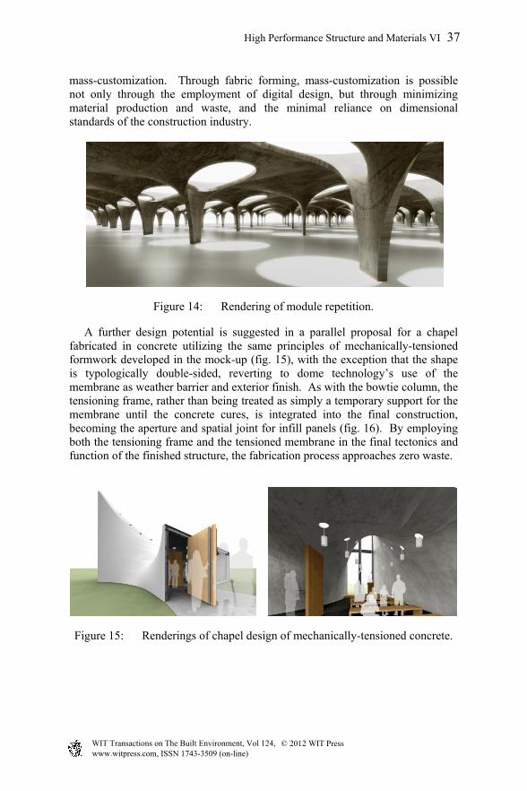
A further design potential is suggested in a parallel proposal for a chapel fabricated in concrete utilizing the same principles of mechanically-tensioned formwork developed in the mock-up (fig. 15), with the exception that the shape is typologically double-sided, reverting to dome technology’s use of the membrane as weather barrier and exterior finish. As with the bowtie column, the tensioning frame, rather than being treated as simply a temporary support for the membrane until the concrete cures, is integrated into the final construction, becoming the aperture and spatial joint for infill panels (fig. 16). By employing both the tensioning frame and the tensioned membrane in the final tectonics and function of the finished structure, the fabrication process approaches zero waste.
Figure 15: Renderings of chapel design of mechanically-tensioned concrete.
High Performance Structure and Materials VI 37
www.witpress.com, ISSN 1743-3509 (on-line) WIT Transactions on The Built Environment, Vol 124, © 201 WIT Press2

Figure 16: Construction staging of chapel design.
6 Conclusions
Much of the contemporary research into digital design and fabrication seeks to reconcile complex geometries possible through digital modelling with a craft of making. Yet many of these techniques struggle with construction industry standards and logics. Fabric-formed concrete bypasses this tension through minimizing material waste in forming an inherently plastic material. This research demonstrates how the use of active tensioning of the formwork and the vocabulary of minimal surfaces builds upon this work by opening an expanded territory of formal exploration only recently made available through increasingly accessible 3d modelling and analysis software.
References
[1] MONOLITHIC, http://www.monolithic.com/topics/about-us [2] Dome Technology, http://www.dometech.com/content/About/About.aspx [3] Balmond, C., Engineering Marsyas at Tate Modern. The Arup Journal,
1/2003, p. 45, 2003. [4] Otto, Frei and Rausch, Bodo, Finding Form: Towards an Architecture of the
Minimal, Axel Menges: Stuttgart, pp 55-57, 1995. [5] Sullivan, J.M., 1993. The Aesthetic Value of Optimal Geometry (Chapter
21). The Visual Mind, ed. M. Emmer, The MIT Press: Cambridge, pp. 547-563, 1993.
[6] Balmond, C., Engineering Marsyas at Tate Modern. The Arup Journal, 1/2003, pp. 40-45, 2003.
38 High Performance Structure and Materials VI
www.witpress.com, ISSN 1743-3509 (on-line) WIT Transactions on The Built Environment, Vol 124, © 201 WIT Press2