the arm cortex-m0 processor architecture...
TRANSCRIPT
1ARM University ProgramCopyright © ARM Ltd 2013
The ARM Cortex-M0 Processor Architecture Part-1

2ARM University ProgramCopyright © ARM Ltd 2013
Module Syllabus ARM Architectures and Processors
What is ARM Architecture
ARM Processors Families
ARM Cortex-M Series Family
Cortex-M0 Processor
ARM Processor Vs. ARM Architectures
ARM Cortex-M0 Processor
Cortex-M0 Processor Overview
Cortex-M0 Block Diagram
Cortex-M0 Registers
Cortex-M0 Memory Map
Cortex-M0 Exception Handling

3ARM University ProgramCopyright © ARM Ltd 2013
ARM Architectures and ARM Processors

4ARM University ProgramCopyright © ARM Ltd 2013
What is ARM Architecture ARM architecture is a family of RISC-based processor architectures
Well-known for its power efficiency;
Hence widely used in mobile devices, such as smartphones, and tablets
Designed and licensed to a wide eco-systems by ARM.
ARM Holdings
The company designs ARM-based processors;
Does not manufacture, but licenses designs to semiconductor partners who fabricate and sell to their customers;
Also offer other designs available, such as physical IPs, graphics cores, and development tools.

5ARM University ProgramCopyright © ARM Ltd 2013
ARM Processor Families Cortex-A series (Application)
High performance processors for open Operating Systems;
Applications include smartphones, digital TV, smart books, home gateways;
Cortex-R series (Real-time) Exceptional performance for real-time applications; Applications include automotive braking systems,
powertrains;
Cortex-M series (Microcontroller) Cost-sensitive solutions for deterministic
microcontroller applications; Applications include microcontrollers, mixed signal
devices, smart sensors, automotive body electronics and airbags;
SecurCore series High security applications.
Previous classic processors Include ARM7, ARM9, ARM11 families
Cortex-A
Cortex-A57
Cortex-A53
Cortex-A15
Cortex-A9
Cortex-A8
Cortex-A7
Cortex-A5
Cortex-R7
Cortex-R5
Cortex-R4
Cortex-M4
Cortex-M3
Cortex-M1
Cortex-M0+
Cortex-M0
SC000
SC100
SC300
ARM11
ARM9
ARM7
Cortex-R
Cortex-M
SecurCore
Classic
As of Sept 2013

6ARM University ProgramCopyright © ARM Ltd 2013
Design an ARM-based SoC Select a set of IP cores from ARM or other third-party IP vendors;
Integrate IP cores into a single chip design;
Give design to semiconductor foundries for chip fabrication.
ARM-basedMCU Chip
ROMROM ARMprocessor
ARMprocessor RAMRAM
System busSystem bus
PeripheralsPeripherals
External InterfaceExternal Interface
SoC
SoC Design Chip ManufactureLicensable IPs
IP libraries
Cortex-A9Cortex-A9 Cortex-R5Cortex-R5 Cortex-M0Cortex-M0
ARM7ARM7 ARM9ARM9 ARM11ARM11
AXI busAXI bus AHB busAHB bus APB busAPB bus
GPIOGPIO I/O blocksI/O blocks TimerTimer
DRAM ctrlDRAM ctrl FLASH ctrlFLASH ctrl SRAM ctrlSRAM ctrl

7ARM University ProgramCopyright © ARM Ltd 2013
ARM Cortex-M Series Family Cortex-M series: Cortex-M0, M0+, M1, M3, M4.
Energy-efficiency
Lower energy costs, longer battery life
Smaller code
Lower silicon costs
Ease of use
Faster software development and reuse
Embedded applications
Smart metering, human interface devices, automotive and industrial control systems, white goods, consumer products and medical instrumentation
As of Sept 2013

8ARM University ProgramCopyright © ARM Ltd 2013
ARM Cortex-M Series Family
Processor ARM
Architecture
CoreArchitect
ureThumb® Thum
b®-2HardwareMultiply
HardwareDivide
SaturatedMath
DSPExtens
ions
FloatingPoint
Cortex-M0 ARMv6-MVon
NeumannMost
Subset
1 or 32 cycle
No No No No
Cortex-M0+ ARMv6-MVon
NeumannMost
Subset
1 or 32 cycle
No No No No
Cortex-M1 ARMv6-MVon
NeumannMost
Subset
3 or 33 cycle
No No No No
Cortex-M3 ARMv7-M Harvard Entire Entire 1 cycle Yes Yes No No
Cortex-M4 ARMv7E-M Harvard Entire Entire 1 cycle Yes Yes Yes Optional

9ARM University ProgramCopyright © ARM Ltd 2013
Cortex-M0 Processor The smallest ARM processor
Exceptionally small silicon area
Ultra-low gate count (approx. 12k gates at minimum configuration)
High code density
Fundamental base of 16-bit Thumb instructions
Additional powerful 32-bit instructions
Lower power
16µW/MHz (90LP process, minimal configuration)
Simplicity
Only 56 instructions
C friendly
More deterministic response time
Uses ARMv6-M Architecture

10ARM University ProgramCopyright © ARM Ltd 2013
ARM Processor Vs. ARM Architectures ARM architecture
Describes the details of instruction set, programmer’s model, exception model, and memory map;
Documented in the Architecture Reference Manual;
ARM processor Developed using one of the ARM architectures;
More implementing details, such as timing information and implementation-related information;
Documented in processor’s Technical Reference Manual.
ARMv4/ V4t Architecture
ARMv5/ v4E Architecture
ARMv6 Architecture
ARMv7Architecture
ARM v6-Me.g. Cortex-M0, M1
e.g. ARM7TDMI e.g. ARM9926EJ-S e.g. ARM1136
ARMv8 ArchitectureARMv7-A
e.g. Cortex-A9
ARMv7-Re.g. Cortex-R4
ARMv7-Me.g. Cortex-M3
ARMv8-Ae.g. Cortex-A53
Cortex-A57
ARMv8-R
As of Sept 2013

11ARM University ProgramCopyright © ARM Ltd 2013
ARM Processor Vs. ARM Architectures Cortex-M0: v6-M
ARMv6 architecture’s thumb instruction set;
ARMv7-M architecture memory map, exception model, and thumb-2 system;
Low power optimised design.
ARM v6-MArchitectureARM v6-M
Architecture
ARM v6Architecture
ARM v6Architecture
ARM v7-MArchitectureARM v7-M
Architecture
ARMCortex-M0
Thumb Instruction set
Memory mapException ModelThumb-2 system
Low power optimizeddesign

12ARM University ProgramCopyright © ARM Ltd 2013
ARM Cortex-M0 ProcessorOverview

13ARM University ProgramCopyright © ARM Ltd 2013
Cortex-M0 Overview 32-bit Reduced Instruction Set Computing (RISC) processor
Von-Neumann architecture
Both data and instructions share a single bus interface;
Instruction set
56 instructions as a subset of Thumb-1 (16-bit) and Thumb-2 (16/ 32-bit);
Supported Interrupts
Non-maskable Interrupt (NMI) + 1 to 32 physical interrupts
Supports Sleep Modes

14ARM University ProgramCopyright © ARM Ltd 2013
Cortex-M0 Block Diagram
Internal Bus System
AHB LITEBus interface
Wakeup Interrupt
Controller (WIC)
ProcessorCore
Nested Vector Interrupt Controller
(NVIC)
DebugSubsystem
Interrupt Requests and NMI
ARM Cortex-M0 Microprocessor
Memory and peripherals
JTAG/Serial-WireDebug Interface
Power management
interface

15ARM University ProgramCopyright © ARM Ltd 2013
Cortex-M0 Block Diagram Processor core
Contains internal registers, the ALU, data path, and some control logics;
Three-stage pipeline: fetch, decode, and execution;
Registers include sixteen 32-bit registers for both general and special usages.
Nested Vectored Interrupt Controller (NVIC)
Up to 32 interrupt request signals and a non-maskable interrupt (NMI);
Automatically handles nested interrupts, such as comparing priorities between interrupt requests and the current priority level;
Fetch Decode Execute
Fetch Decode Execute
Fetch Decode Execute
Instruction 1
Instruction 2
Instruction 3
Fetch Decode ExecuteInstruction 4
Time

16ARM University ProgramCopyright © ARM Ltd 2013
Cortex-M0 Block Diagram Bus system
Includes the internal bus system, the data path in the processor core, and the AHB LITE interface unit;
All 32 bits wide;
AHB LITE is an on-chip bus protocol for many ARM processors and widely used in IC design industry.
Debug subsystem
Handles debug control, program breakpoints, and data watchpoints;
When a debug event occurs, it can put the processor core in a halted state, where developers can analyse the status of the processor at that point, such as register values and flags.
Wakeup Interrupt Controller (WIC) (optional)
For low-power applications, the microcontroller can enter sleep mode by shutting down most of the components.
When an interrupt request is detected, the WIC can inform the power management unit to power up the system.

17ARM University ProgramCopyright © ARM Ltd 2013
ARM Cortex-M0 ProcessorRegisters

18ARM University ProgramCopyright © ARM Ltd 2013
Cortex-M0 Registers Processor registers
The internal registers are used to store and process temporary data within the processor core;
All registers are inside the processor core hence can be accessed more quickly;
Load-store architecture
To process a data in the memory, they have to be loaded from the memory to a register, processed inside the processor, and then written back to the memory if needed;
Cortex-M0 register
Register bank
Sixteen 32-bit registers (thirteen are used for general-purpose);
Special registers;

19ARM University ProgramCopyright © ARM Ltd 2013
Cortex-M0 Registers
R0
R1
R2
R3
R4
R5
R6
R7
R8
R9
R10
R11
R12
R13(banked)
R14
R15
x PSR
Stack Pointer (SP)
Link Register (LR)
Program Counter (PC)
PRIMASK
CONTROL
Program Status Registers (PSR)
Interrupt mask register
Stack definition
Special registers
Register bank
MSP
PSP
Main Stack Pointer
Process Stack Pointer
APSR EPSR IPSR
ApplicationPSR
ExecutionPSR
InterruptPSR
LowRegisters
HighRegisters
General purpose register

20ARM University ProgramCopyright © ARM Ltd 2013
Cortex-M0 Registers R0 – R12: general purpose registers
Low registers (R0 – R7) can be accessed by any instruction;
High registers (R8 – R12) sometimes cannot be accessed by some Thumb instructions;
R13: Stack Pointer (SP) Records the current address of the stack
Used for saving the context of a program while switching between tasks
Cortex-M0 has two SPs: Main SP, used in applications that require privileged access e.g. OS kernel, and exception handlers, and Process SP, used in base-level application code (when not running an exception handler)
Program Counter (PC) Records the address of the current instruction code;
Automatically incremented by 4 at each operation (for 32-bit instruction code), except branching operations;
A branching operation, such as function calls, will change the PC to a specific address, meanwhile save the current PC to the Link Register (LR);
Data Data
PC
SP
Address
Low
High
PUSH POP
Stack
Code
Heap

21ARM University ProgramCopyright © ARM Ltd 2013
Cortex-M0 Registers
R14: Link Register (LR)
The LR is used to store the return address of a subroutine or a function call;
The program counter (PC) will load the value from LR after a function is finished;
PC
LR
MainProgram
code
subroutineCurrent PC
Load PC with the address in LR to return to the main program
Current LR
Return from a subroutine to the main program
PC
LR
MainProgram
code
subroutine
Current PC
1. Save currentPC to LR
2. Load PC with the starting address of the subroutine
Call a subroutine
Code
region
Cod
e region

22ARM University ProgramCopyright © ARM Ltd 2013
Cortex-M0 Registers
xPSR, combined Program Status Register
Provides the information about program execution and the ALU flags;
Application PSR (APSR)
Interrupt PSR (IPSR)
Execution PSR (EPSR)
N Z C V
ISR number
Reserved
Reserved
ReservedT
ReservedTN Z C V ISR number
APSR
IPSR
EPSR
xPSR
bit0bit8bit16bit24bit31

23ARM University ProgramCopyright © ARM Ltd 2013
Cortex-M0 Registers APSR
N: negative flag
Set to one if the result from ALU is negative;
Z: zero flag
Set to one if the result from ALU is zero;
C: carry flag
Set to one if an unsigned overflow occurs;
V: overflow flag
Set to one if a signed overflow occurs;
IPSR ISR number
Current executing interrupt service routine number
EPSR T: Thumb state
Always one since Cortex-M0 only supports the Thumb state

24ARM University ProgramCopyright © ARM Ltd 2013
Cortex-M0 Registers PRIMASK: Interrupt Mask Special Register
1-bit PRIMASK
Set to one will block all the interrupts apart from nonmaskable interrupt (NMI) and the hard fault exception;
CONTROL: special register
1-bit stack definition
Set to one: use the process stack pointer (PSP);
Clear to zero: use the main stack pointer (MSP).
Reserved
Reserved
PRIMASK
PRIMASK
CONTROL
bit8bit16bit24bit31
Stack definition

25ARM University ProgramCopyright © ARM Ltd 2013
ARM Cortex-M0 ProcessorMemory Map

26ARM University ProgramCopyright © ARM Ltd 2013
Cortex-M0 Memory Map The Cortex-M0 processor has 4 GB of memory address space
The 4GB memory space is architecturally defined as a number of regions.
Each region is given for recommended usage;
Easy for software programmer to port between different devices.
Nevertheless, despite of the default memory map, the actual usage of the memory map can also be flexibly defined by the user, except some fixed memory addresses, such as internal private peripheral bus.

27ARM University ProgramCopyright © ARM Ltd 2013
Cortex-M0 Memory Map
Private peripheralse.g. NVIC, SCS
Mainly used for external peripheralse.g. SD card
Mainly used for external memoriese.g. external DDR, FLASH, LCD
Mainly used for on-chip peripheralse.g. AHB, APB peripherals
Mainly used for data memorye.g. on-chip SRAM, SDRAM
Mainly used for program code e.g. on-chip FLASH
Reserved
External Device
External RAM
Peripherals
SRAM
Code
0xFFFFFFFF
0xE0000000Private Peripheral Bus
0xDFFFFFFF
0xA00000000x9FFFFFFF
0x60000000
0x5FFFFFFF
0x400000000x3FFFFFFF
0x1FFFFFFF0x20000000
0x00000000
512MB
512MB
512MB
1GB
1GB
512MB0xE00FFFFF
0xE0100000
Reserved for other purposes
ROM table
Reserved
System Control Space(SCS)
Reserved
Break point unit
Data watch point unit
Reserved
Debug Control
Nested Vectored Interrupt Controller
(NVIC)
Reserved
SysTick Timer
Reserved
System Control Block(SCB)

28ARM University ProgramCopyright © ARM Ltd 2013
Cortex-M0 Memory Map Code Region
Primarily used to store program code;
Can also be used for data memory;
On-chip memory, such as on-chip FLASH.
SRAM Region
Primarily used to store data, such as heaps and stacks;
Can also be used for program code;
On-chip memory; despite its name “SRAM”, the actual device could be SRAM, SDRAM or other types.
Peripheral Region
Primarily used for peripherals, such as Advanced High-performance Bus (AHB) or Advanced Peripheral Bus (APB) peripherals;
On-chip peripherals.
29ARM University ProgramCopyright © ARM Ltd 2013
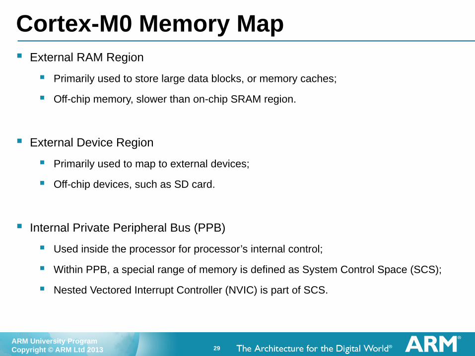
Cortex-M0 Memory Map External RAM Region
Primarily used to store large data blocks, or memory caches;
Off-chip memory, slower than on-chip SRAM region.
External Device Region
Primarily used to map to external devices;
Off-chip devices, such as SD card.
Internal Private Peripheral Bus (PPB)
Used inside the processor for processor’s internal control;
Within PPB, a special range of memory is defined as System Control Space (SCS);
Nested Vectored Interrupt Controller (NVIC) is part of SCS.
30ARM University ProgramCopyright © ARM Ltd 2013
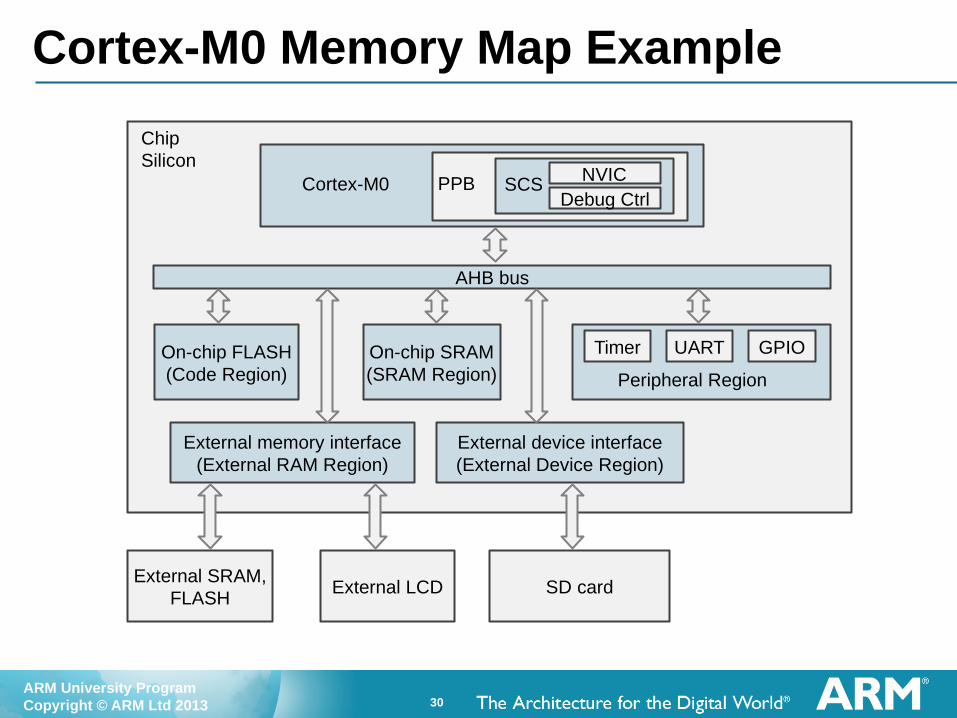
Cortex-M0 Memory Map Example
AHB bus
External SRAM,FLASH
External LCD SD card
Cortex-M0 PPB SCS NVICDebug Ctrl
On-chip FLASH(Code Region)
On-chip SRAM(SRAM Region) Peripheral Region
External memory interface(External RAM Region)
External device interface(External Device Region)
Timer UART GPIO
Chip Silicon

31ARM University ProgramCopyright © ARM Ltd 2013
Cortex-M0 Program Image The program image in Cortex-M0 contains
Vector table -- includes the starting addresses of exceptions (vectors) and the value of the main stack point (MSP);
C start-up routine;
Program code – application code and data;
C library code – program codes for C library functions.
0x00000000 Initial MSP value
Code region
Start-up routine &Program code &C library code
Vector table
ProgramImage
Reset vectorNMI vector
Hard fault vector
Reserved
SVC vector
Reserved
PendSV vectorSysTick vector
Interrupt vectors
0x00000000
0x00000004
0x00000008
0x0000000C
0x0000002C
0x00000038
0x00000040
0x0000003C

32ARM University ProgramCopyright © ARM Ltd 2013
Cortex-M0 Program Image After reset:
1. First reads the initial MSP value;
2. Then reads the reset vector;
3. Branches to the starting of the programme execution address (reset handler);
4. Subsequently executes program instructions.
Reset
Fetch initial value for MSP(Read address 0x00000000)
Fetch reset vector(Read address 0x00000004)
Fetch 1st instruction(Read address of reset vector)
Fetch 2nd instruction(Read subsequent instructions)

33ARM University ProgramCopyright © ARM Ltd 2013
Cortex-M0 Endianness Endian refers to the order of bytes stored in the memory
Little endian: lowest byte of a word-size data is stored in the bit 0 to bit 7
Big endian: lowest byte of a word-size data is stored in the bit 24 to bit 31
Cortex-M0 supports both little endian and big endian
However, Endianness only exists in the hardware level
Byte0Byte1Byte2Byte3
Byte0Byte1Byte2Byte3
Byte0Byte1Byte2Byte3
0x00000000
0x00000004
0x00000008
Address [7:0][15:8][23:16][31:24]
Byte0 Byte1 Byte2 Byte3
Byte0 Byte1 Byte2 Byte3
Byte0 Byte1 Byte2 Byte3
[7:0][15:8][23:16][31:24]
Word 1
Word 2
Word 3
Word 1
Word 2
Word 3
Little endian 32-bit memory Big endian 32-bit memory

34ARM University ProgramCopyright © ARM Ltd 2013
ARM Cortex-M0 ProcessorExceptions

35ARM University ProgramCopyright © ARM Ltd 2013
Cortex-M0 Exception Handling Exceptions are events that cause the program flow to exit the current
program thread, and execute a piece of code associated with the event.
Events can be either internal or external.
The external event is also called interrupt request (IRQ).
ThreadMode
ThreadMode
Exception Mode
Exception Mode
Internal or external event
Executing exception handler
Executing normal code sequence
Finishing handler
Context saving
Context restoring

36ARM University ProgramCopyright © ARM Ltd 2013
Cortex-M0 Exception Handling Exception Handler
A piece of software code that is executed in the exception mode;
If the exception is caused by an IRQ, it can also be called as an interrupt handler, or interrupt service routine (ISR);
Context Switching
Context saving: before entering the exception mode, the current program context, such as current registers values, are pushed onto the stack;
Context restoring: after finishing the handler, the previously stored context is restored by popping register values from the stack.
ThreadMode
ThreadMode
Exception Mode
Exception Mode
Internal or external event
Executing exception handler
Executing normal code sequence
Finishing handler
Context saving
Context restoring

37ARM University ProgramCopyright © ARM Ltd 2013
Cortex-M0 Exception Handling Exception Priority
The exceptions (or interrupts) are commonly divided into multiple levels of priorities;
A higher priority exception can be triggered and serviced during a lower priority exception;
Commonly known as a nested exception.
Exceptions can be disabled or enabled by software.
Cortex-M0 Interrupt Controller
Supports up to 32 IRQ inputs and a non-maskable interrupt (NMI) inputs;
NMI is similar to IRQ but cannot be disabled and has the highest priority, useful for safety critical systems such as industrial control or automotive.

38ARM University ProgramCopyright © ARM Ltd 2013
Vector Table for ARMv6-M First entry contains initial Main SP
All other entries are addresses for exception handlers
Must always have LSBit = 1 (for Thumb)
Table has up to 496 external interrupts Implementation-defined
Maximum table size is 2048 bytes
Table may be relocated Use Vector Table Offset Register
Still require minimal table entries at 0x0 for booting the core
Each exception has a vector number Used in Interrupt Control and State
Register to indicate the active or pending exception type
Table can be generated using C code Example provided later
Reserved (x4)
Usage Fault
Mem Manage Fault
Hard Fault
NMI
Reset
Initial Main SP
0x1C to 0x28
0x18
0x14
0x10
0x0C
0x08
0x04
0x00
16 + N
…
16
15
14
13
12
11SVC
Debug Monitor
Reserved
PendSV
SysTick
External 0
Bus Fault
…
External N0x40 + 4*N
…
0x40
0x3C
0x38
0x34
0x30
0x2C
7-10
6
5
4
3
2
1
N/A
Address Vector #

39ARM University ProgramCopyright © ARM Ltd 2013
Vector Table in Assembly The interrupt vector can be defined in either C language or assembly
language, for example in assembly:
RESERVE8 THUMB IMPORT ||Image$$ARM_LIB_STACK$$ZI$$Limit|| AREA RESET, DATA, READONLY EXPORT __Vectors
__Vectors DCD ||Image$$ARM_LIB_STACK$$ZI$$Limit|| ; Top of Stack DCD Reset_Handler ; Reset Handler DCD NMI_Handler ; NMI Handler DCD HardFault_Handler ; Hard Fault Handler DCD MemManage_Handler ; MemManage Fault Handler DCD BusFault_Handler ; Bus Fault Handler DCD UsageFault_Handler ; Usage Fault Handler DCD 0, 0, 0, 0, ; Reserved x4 DCD SVC_Handler, ; SVCall Handler DCD Debug_Monitor ; Debug Monitor Handler DCD 0 ; Reserved DCD PendSV_Handler ; PendSV Handler DCD SysTick_Handler ; SysTick Handler ; External vectors start here