the ballistic properties of tool steel as a potential
TRANSCRIPT

Pergamon Int. J. Impact Engng Vol. 19, No. 4, pp. 297 309, 1997
,~: 1997 Elsevier Science Ltd Printed in Great Britain. All rights reserved
PII: S0734-743X(96)00043--7 0734-743X/97 $17.00 + 0.00
T H E B A L L I S T I C P R O P E R T I E S O F T O O L S T E E L A S A P O T E N T I A L I M P R O V I S E D A R M O U R P L A T E
M. R. EDWARDS and A. MA TH EW S O N School of Engineering and Applied Science, Cranfield University, Royal Military College of Science,
Shrivenham, Swindon SN6 8LA, U.K.
(Received 20 March 1996; in revised form 24 July 1996)
Summary- -The ballistic behaviour of a 0.95 weight per cent carbon tool steel against 7.62 mm ball and armour piercing bullets was investigated in the unwelded and welded condition. Gross cracking occurred at plate hardnesses of 510 HV and greater. The mode of perforation for tool steel of hardness 380 HV, which was petalling for 5 mm thick plates and ductile hole formation, followed by discing, for l0 mm thick plates, was similar to that of conventional armour plates of comparable hardness. The ballistic limit increased more with plate hardness for the deforming ball projectile than for the non-deforming armour piercing round. For the latter the ballistic limit was similar to that for rolled homogeneous armour of similar hardness. All welded assemblies suffered from heat affected zones with hardnesses greater than 500 HV, and for the thinner plates, there was hydrogen-induced cold cracking which split the plate before ballistic testing could be completed. Thus an improvised armour could be made from a commercial tool steel, provided the hardness was kept to 380 HV and below and that there were no welds in the assembly. Better improvised armours could be created from other commercial low alloy steel plate of lower carbon content, heat treated to 380 HV, where the welding would be more easily carried out. Welding would be best performed using austenitic electrodes and pre-heating of the plate, with a double V-butt weld configuration to reduce macroscopic distortion. (q', 1997 Elsevier Science Ltd. All rights reserved.
Keywords: terminal ballistics, tool steel, improvised armours.
NOTATION
HB Brinell hardness HV Vickers hardness t thickness of armour K fracture toughness a r yield strength A P armour piercing Vs0 initial projectile velocity for which there is a 50% probability of penetration GMAW gas metal arc welding SMAW shielded metal arc welding GTAW gas tungsten arc welding HAZ heat affected zone RHA rolled homogeneous armour
I N T R O D U C T I O N
The earliest monolithic armours were derived from the 0.25 weight per cent carbon nickel-chromium steels that were used in the face-hardened naval armours used in armoured battleships [1]. These were used at varying hardnesses up to 650 HB, but normally at lower hardnesses. Process details were included in the description of the steels, such as the comment that finish rolling of the steel had to be carried out at 850°C. In a 1941 review of alloys for armour [2] it was emphasised that steels had to be carefully processed, for example by using electric arc manufacture, in order to prevent cracking and spalling at armour hardnesses. These were around 300-330 HB for thick armour, although thin armours could be produced up to 390 HB for machinable armour and 440-475 HB for hard armours. Carbon contents varied, with a tendency to reduced carbon values in the more modern steels in order to aid welding, the maximum reported being 0.53 weight per cent for a German chromium- molybdenum steel heat treated to a hardness of 350 HB. These armours were produced to military specifications and their supply was restricted to approved customers.
297
298 M.R. Edwards and A. Mathewson
The occurrence of gross cracking on impact has been associated with thick armours, and with steels of high hardness. Belk [3] has shown that the thickness of armour that can be used without risk of cracking is related to the material toughness and yield strength by the equation:
t oc (K/or) 2
indicating that gross cracking is more likely for thick hard armours and, for a fixed yield strength (hardness), a low fracture toughness.
For the majority of armour applications, the steel should be welded. The main problems in welding steels of greater than 0.25 weight per cent carbon are concerned with the formation of very hard untempered martensite in the heat affected zone, as well as the occurrence of cold cracking, associated with hydrogen migration from the weld pool to the heat affected zone. Studies by Ritter, Dixon and Baldwin [4] on a (weight per cent) C 0.42, Cr 1.36, Ni 0.23, Mo 0.75, V 0.22, Mn 0.74, Si 0.29, S 0.004, P 0.009, balance Fe armour plate, heat treated to 445 HV, showed that cold cracking was associated with very high HAZ hardnesses or with a ferritic electrode that had not been dried before use. However, even when a baked austenitic steel welding electrode was used, hardnesses in the HAZ still reached 500 HV.
The welding behaviour of low alloy steels with carbon contents equal to and higher than those described by Ritter [-4] has been summarised in Ref. [5]. For these alloys it is necessary to take great care over the welding with the use ofpre-heating and multiple passes, so that any martensite formed in early passes may be tempered in subsequent passes. Additionally low- hydrogen welding electrodes, preferably baked immediately before welding, should be used. Ideally the whole welded assembly should be heat-treated after welding.
Because of the improved manufacturing processes currently being used for the manufac- ture of commercial plate steel, it should be possible to employ a wider range of carbon and alloying element contents in improvised armour plates, although some compositions may only be capable of being used in an unwelded assembly. This may be useful where current armour plate steels are unobtainable. Situations where this could be possible are the temporary armouring of civil lorries and cars in areas of civil conflict or the production of improvised armoured vehicles by guerilla and terrorist forces, following the van Creveld model of "transformed" war [6].
The aim of the present work is to examine the ballistic behaviour of a commercially available high carbon steel plate at various hardness levels, and to show how the ballistic behaviour changes when welds are present.
EXPERIMENTAL
Materials used
The tool steel used was supplied to BS 4659 BO1 and had a composition of (weight per cent) C 0.91, Mn 1.11, Si 0.22, Cr 0.48, W 0.50, V 0.14, S 0.012, P 0.009, balance Fe. It was supplied in the annealed condition in thicknesses of 5.0 mm and 10.0 mm and had a hardness of 200 HV. For ballistic trials the plates were heated to 800°C, quenched in oil and tempered to give hardnesses of 710 HV, 510 HV and 380 HV. As a control 5 mm and 10 mm thick mild steel plates, composition (weight per cent) C 0.19, Mn 1.02, Si 0.03, S < 0.005, P 0.015, balance Fe and hardness 133 HV, were used.
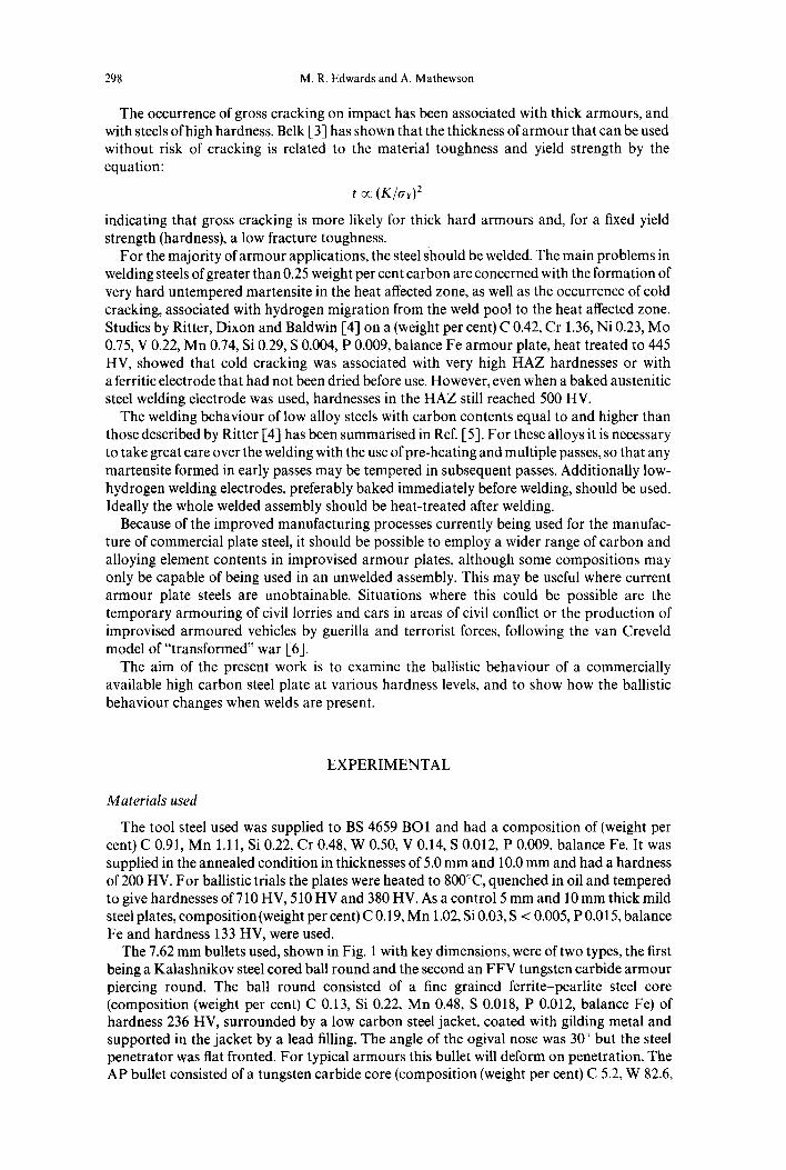
The 7.62 mm bullets used, shown in Fig. 1 with key dimensions, were of two types, the first being a Kalashnikov steel cored ball round and the second an FFV tungsten carbide armour piercing round. The ball round consisted of a fine grained ferrite-pearlite steel core (composition (weight per cent) C 0.13, Si 0.22, Mn 0.48, S 0.018, P 0.012, balance Fe) of hardness 236 HV, surrounded by a low carbon steel jacket, coated with gilding metal and supported in the jacket by a lead filling. The angle of the ogival nose was 30 ° but the steel penetrator was flat fronted. For typical armours this bullet will deform on penetration. The AP bullet consisted of a tungsten carbide core (composition (weight per cent) C 5.2, W 82.6,

The ballistic properties of tool steel 299
Diameter of core 5.59 m m Angle of core tip 60 ° Length o f core 20.15 m m Mass of core 5.91 g
c m
Diameter of core 5.77 m m Length of core 19.61 m m Mass of core 3.56 g
Fig. 1. 7.62 m m armour piercing round (top) and ball round (bottom) with key dimensions.
Co 10.5, Fe 0.41) of hardness 1200 HV, mounted in a low carbon steel jacket, coated with gilding metal, on an aluminium cup. The angle of the penetrator core was 60 °. There was an air gap between the front of the penetrator and the jacket. This bullet will not deform on penetration, even for the highest hardness armours, since the penetrator remains rigid when its hardness exceeds 1.5 times the hardness of the target [7]. The deformation of the ball round and the rigidity of the AP penetrator are seen in Fig. 2. Further details of the projectiles may be found in Ref. [8].
The welding rods used were either of austenitic stainless steel (E312-16, composition (weight per cent) C 0.1, Cr 30, Ni 9.5, Si 1.0, Mn 0.8, bal Fe) or mild steel (A5 18 ER 70, composition (weight per cent) C 0.12, Mn 1.3, Si 0.9, bal Fe). In the case of the SMAW process the rods were kept in plastic bags until welding was carried out, but there was no pre-heating of the rods to remove moisture. For the welding wire used in the GMAW process the wire was coated but again not pre-heated.
Fig. 2. From left to right: (a) ball round impacting target (200 HV) at 500 m s - 1 ; (b) ball round impacling target (386 HV) at 580 m s - l; (c) ball round impacting target (698 HV) at 718 ms ~; (d) A P round showing lack of deformation; and (e) AP round failing by brittle fracture during penetration.

300 M.R. Edwards and A. Mathewson
Methods
The rounds were fired from a proof barrel (AP) or an AK47 assault rifle (ball), in each case securely mounted to the weapon stand, at a distance of 15 m from the target, which was in the form of a rigidly held 300 mm x 250 mm plate. All firings were carried out at zero obliquity. A laser designator was used to achieve accurate aiming and the velocity was measured by optical gates placed before and behind the target. The projectile velocity was altered by reducing the amount of propellant in the cartridge case.
The ballistic behaviour was characterised by the 1/5o limit velocity, calculated by the procedures of Ref. [9], where the 1/5o limit velocity is calculated by averaging the three highest velocities producing partial penetration and the three lowest velocities producing complete penetration. For a valid 1/5o these six velocities must be within a range of 46 ms- 1.
Welding was either carried out using a mild steel electrode by the gas-metal arc (GMAW) process or a stainless steel electrode by the shielded metal arc (SMAW) process (second and subsequent passes) following a root run by gas tungsten-arc (GTAW) welding. The 5 mm plate was welded in two passes, while the 10 mm plate required four passes. All welds were produced in the flat downhand position and were unrestrained: normally single 60 ° V-butt welds were used, although some used a double 60 ° V-butt weld. Pre-heating, when used, was at a temperature of 220°C. Further details of the welding procedures can be found in Ref. [-10].
Optical microscopy was carried on polished and etched cross-sections of the welded joints. Scanning electron microscopy of fractured samples was performed on a JEOL JSM T330 A microscope, while energy-dispersive X-ray analysis on a JEOL JSM840A scanning electron microscope was used to perform an approximate chemical analysis of the welded joint as a function of distance from the weld centre line.
RESULTS
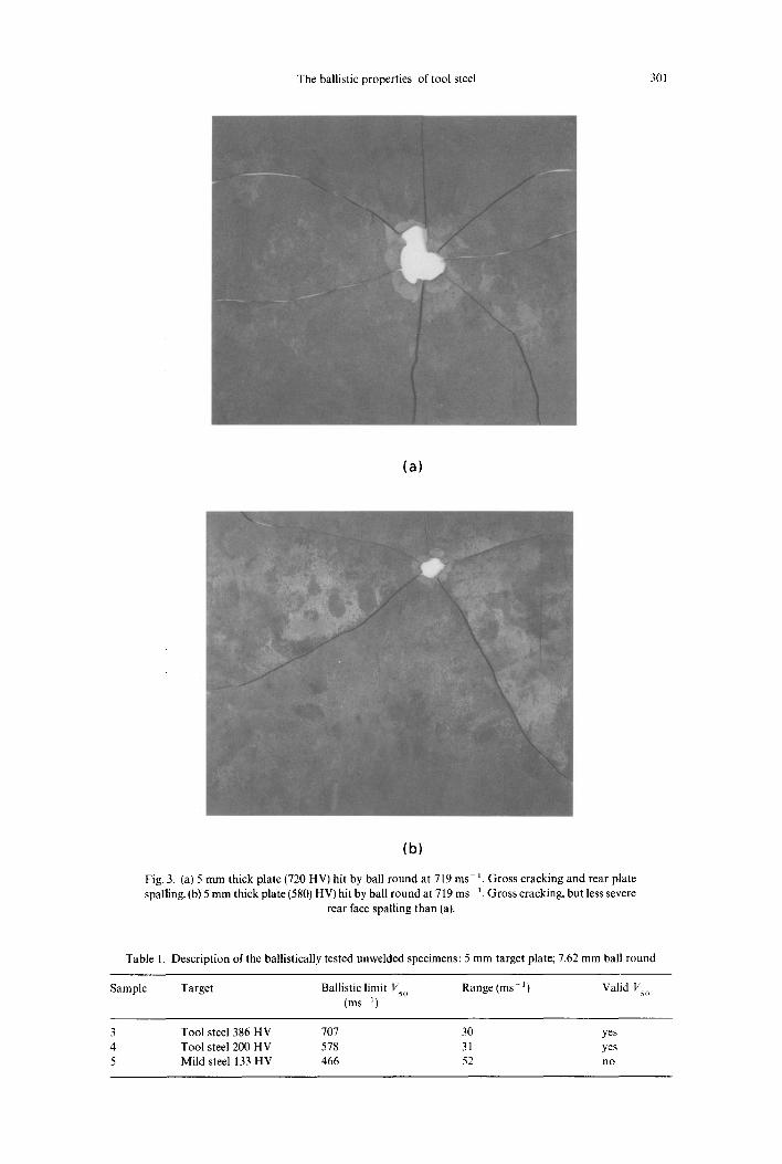
All bullets fired at the plates hardened to 510 and 710 HV produced gross cracking, whether in 10 mm or 5 mm plate thicknesses or if a soft ball round or hard armour piercing round was used. Examples are shown in Fig. 3. For that reason, all subsequent testing was carried out on the plates heat treated to 380 HV or on an annealed plate.
1/5o values for the unwelded plates are listed in Tables 1 and 2. Comparative data for RHA were taken from [11]. The thin unwelded plate showed evidence of petalling (Fig. 4), both at 386 HV and at 200 HV, while the thicker plate (Fig. 5) failed by ductile flow and discing with the formation of thick petals. For the 5 mm welded plate there were two characteristic modes of failure. Either the sample failed due to delayed cracking after welding but before ballistic testing, or the failure was along the HAZ (Fig. 6) after the first firing. The HAZ fractures showed some intergranular areas, indicating the presence of hydrogen embrittlement. A summary of the firing trials carried out on 5 mm plate is in Table 3. 1/5o values for the welded plates described in Table 4 are in Fig. 7.
Hardened and tempered plates that had not been preheated (samples 15 and 16) formed cracks at the root of the weld, together with evidence of rear face spalling (Fig. 8) Annealed plates which had been preheated (samples 17 and 18) did not form root cracks but did suffer rear face spalling (Fig. 9). Double V-weld prepared specimens (samples 19 and 20) neither formed root cracks, except during firing in the case of the non-preheated sample, or suffered rear face spalling.
Macroscopic distortion of the welded assemblies was always greater when the shielded metal arc welding process with stainless steel electrodes, rather than the gas metal arc welding process with mild steel electrodes, was used. The specimens welded with a double V-butt weld suffered minimal distortion.
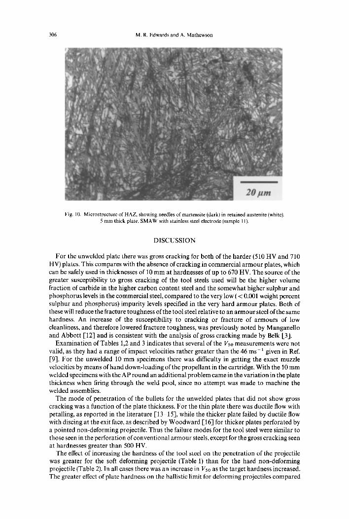
The hardness in the HAZ was associated with a coarse martensitic structure with retained austenite (Fig. 10), produced by the fast cooling from welding temperatures of the high carbon tool steel. The maximum HAZ hardness was adjacent to the weld pool, where the peak temperature was at its highest.
The ballistic properties of tool steel 301
(a)
(b)
Fig. 3. (a) 5 mm thick plate (720 HV) hit by ball round at 719 ms ~. Gross cracking and rear plate spalling. (b) 5 mm thick plate (580) HV) hit by ball round at 719 ms- 1. Gross cracking, but less severe
rear face spalling than (a).
Table 1. Description of the ballistically tested unwelded specimens: 5 mm target plate; 7.62 mm ball round
Sample Target Ballistic limit Vso Range (ms- 1) Valid Vso (ms 1)
3 Tool steel 386 HV 707 30 yes 4 Tool steel 200 HV 578 31 yes 5 Mild steel 133 HV 466 52 no

302
Table 2. Description of the ballistically tested unwelded specimens: 10 mm target plate; 7.62 mm AP round
Sample Target Ballistic limit Vso (ms - ~) Range (ms - 1) Valid Vs0
7 Tool steel 364 HV 588 83 no 8 Tool steel 200 HV 502 77 no
RHA [-11] 340 HV 520
(a)
(b)
Fig. 4. (a) 5 mm thick annealed plate (205 HV) hit by ball round, showing petalling on rear face. (b) 5 mm thick heat treated plate (386 HV), hit by ball round, showing petalling but less plastic
deformation than (at.

The ballistic properties of tool steel 303
Fig. 5. Part penetrated AP round in 10 mm thick heat treated plate (364 HV), showing ductile flow and the formation of thick petals that shear off.
Fig. 6. Brittle failure along HAZ on first impact. 5 mm thick plate (373 HV), GMAW with mild steel electrode (sample 9); hit by ball round at 657 ms- 1.

304 M.R. Edwards and A. Mathewson
Table 3. Results from ballistically tested 5 mm thick welded plates; 7.62 mm ball round; aim point weld pool
Sample Target HAZ hard- Results ness (HV)
9 Tool steel 373 HV, mild steel 800 Cold cracking along HAZ (Fig. 6) electrode. Weld pool 270 HV after first impact at 657 ms 1.
12 Tool steel 200 HV, mild steel 680 Cold cracking along HAZ after electrode. Weld pool 270 HV six firings.
10 Tool steel 200 HV stainless steel 700 Cold cracking along HAZ after electrode. Weld pool 270 HV first firing.
Table 4. Description of ballistically tested 10 mm thick welded plates; 7.62 mm AP round; aim point weld pool
Sample Target HAZ Ballistic Range Valid hardness limit Vs0 (ms l) 1/5o (HV) (ms 1)
15 Tool steel 376 HV, mild steel 720 (surface) 510 74 no electrode. Weld pool 200 HV 700 (centre)
16 Tool steel 395 HV, stainless 730 (surface) 515 estimate steel electrode. Weld pool 550 (centre) 210 HV
17 Tool steel 200 HV, mild steel 700 (surface} 495 39 yes electrode, preheated. Weld 600 (centre) pool 200 HV
18 Tool steel 200 H V, stainless 700 (surface) 498 41 yes steel electrode, preheated. 600 (centre} Weld pool 210 HV
19 Tool steel 367 HV, mild steel 600 (surface) 545 53 no electrode, double V weld 400 (centre) preparation. Weld pool 260 HV
20 Tool steel 367 HV, mild steel 580 (surface) 554 45 yes electrode, double Vweld 380 (centre) preparation, preheat. Weld pool 260 HV
21 Mild steel 133 HV, mild steel 484 53 no electrode
10ram plate FFV AP Projectile
550 -
500-
450 -
400
i Double V i SingleV ~
i ' 1
Sample Sample Sample Sample Sample Sample 15 16 17 18 19 20
RI--IA Sample 21
Fig. 7. Ballistic limit (1/5o for 7.62 mm AP round against 10 mm thick welded target plates), Sample numbers after Tables 2 and 3. RHA results after [11].

The ballistic properties of tool steel 305
Fig. 8. Root cracking and rear face spalling in welded specimen. 10 mm thick heat-treated plate (395 HV), SMAW with stainless steel electrode and no pre-heat.
Fig. 9. Rear face spalling with absence of root cracks in welded specimen. 10 mm annealed plate (205 HV), GMAW with mild steel electrode and pre-heated.
Weld metal structures depended principally on the filler metal used. With a mild steel filler the structure was acicular ferrite, with either fine pearlite or upper bainite, depending on cooling rate. Welds produced with stainless steel filler gave an austeni te-ferr i te structure, as would be expected from considera t ion of the composi t ion of the weld metal. In all weld runs the hardness of the weld metal (Table 4) was substant ia l ly less than that of the HAZ.
306 M.R. Edwards and A. Mathewson
Fig. 10. Microstructure of HAZ, showing needles of martensite (dark) in retained austenite (white). 5 mm thick plate, SMAW with stainless steel electrode (sample 11).
DISCUSSION
For the unwelded plate there was gross cracking for both of the harder (510 HV and 710 HV) plates. This compares with the absence of cracking in commercial armour plates, which can be safely used in thicknesses of 10 mm at hardnesses of up to 670 HV. The source of the greater susceptibility to gross cracking of the tool steels used will be the higher volume fraction of carbide in the higher carbon content steel and the somewhat higher sulphur and phosphorus levels in the commercial steel, compared to the very low ( < 0.001 weight percent sulphur and phosphorus) impurity levels specified in the very hard armour plates. Both of these will reduce the fracture toughness of the tool steel relative to an armour steel of the same hardness. An increase of the susceptibility to cracking or fracture of armours of low cleanliness, and therefore lowered fracture toughness, was previously noted by Manganello and Abbott [12] and is consistent with the analysis of gross cracking made by Belk [3].
Examination of Tables 1,2 and 3 indicates that several of the Vso measurements were not valid, as they had a range of impact velocities rather greater than the 46 ms- 1 given in Ref. [9]. For the unwelded 10 mm specimens there was difficulty in getting the exact muzzle velocities by means of hand down-loading of the propellant in the cartridge. With the 10 mm welded specimens with the AP round an additional problem came in the variation in the plate thickness when firing through the weld pool, since no attempt was made to machine the welded assemblies.
The mode of penetration of the bullets for the unwelded plates that did not show gross cracking was a function of the plate thickness. For the thin plate there was ductile flow with petalling, as reported in the literature [13-15], while the thicker plate failed by ductile flow with discing at the exit face, as described by Woodward [16] for thicker plates perforated by a pointed non-deforming projectile. Thus the failure modes for the tool steel were similar to those seen in the perforation of conventional armour steels, except for the gross cracking seen at hardnesses greater than 500 HV.
The effect of increasing the hardness of the tool steel on the penetration of the projectile was greater for the soft deforming projectile (Table 1) than for the hard non-deforming projectile (Table 2). In all cases there was an increase in I15o as the target hardness increased. The greater effect of plate hardness on the ballistic limit for deforming projectiles compared
The ballistic properties of tool steel 307
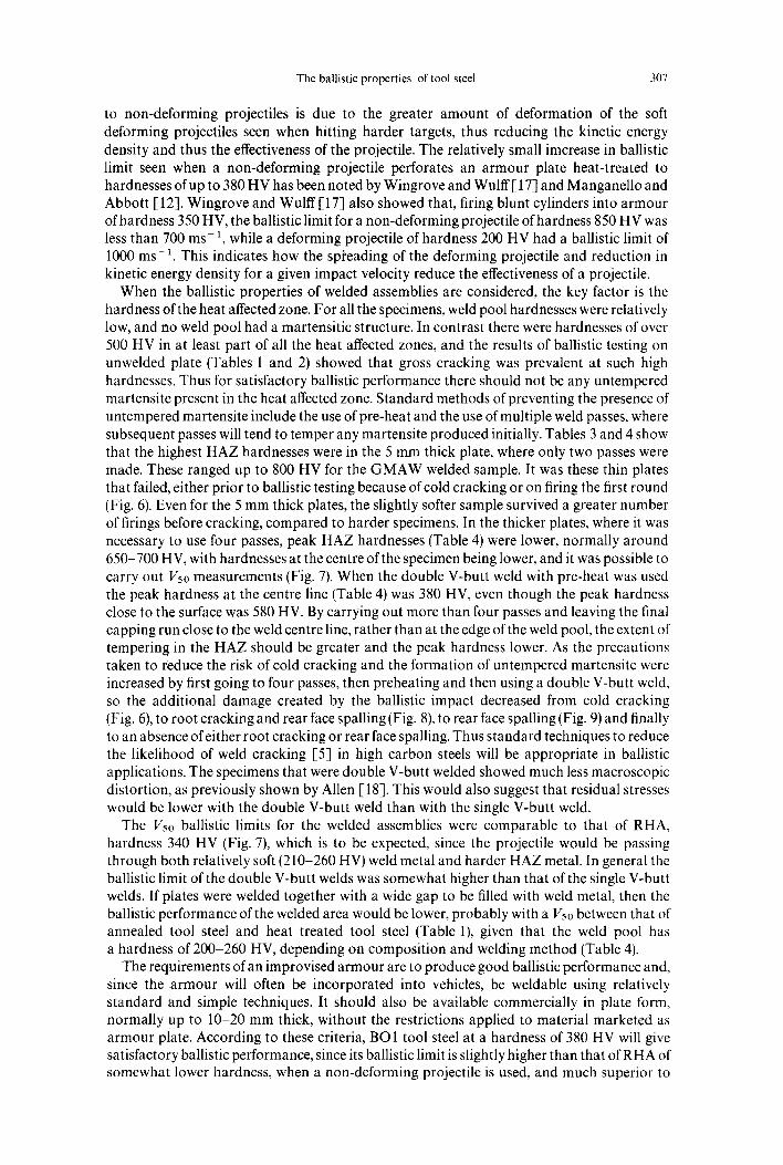
to non-deforming projectiles is due to the greater amount of deformation of the soft deforming projectiles seen when hitting harder targets, thus reducing the kinetic energy density and thus the effectiveness of the projectile. The relatively small imcrease in ballistic limit seen when a non-deforming projectile perforates an armour plate heat-treated to hardnesses of up to 380 HV has been noted by Wingrove and Wulff [ 17] and Manganello and Abbott [ 12]. Wingrove and Wulff [17] also showed that, firing blunt cylinders into armour of hardness 350 HV, the ballistic limit for a non-deforming projectile of hardness 850 HV was less than 700 ms 1, while a deforming projectile of hardness 200 HV had a ballistic limit of 1000 ms 1. This indicates how the spi~eading of the deforming projectile and reduction in kinetic energy density for a given impact velocity reduce the effectiveness of a projectile.
When the ballistic properties of welded assemblies are considered, the key factor is the hardness of the heat affected zone. For all the specimens, weld pool hardnesses were relatively low, and no weld pool had a martensitic structure. In contrast there were hardnesses of over 500 HV in at least part of all the heat affected zones, and the results of ballistic testing on unwelded plate (Tables 1 and 2) showed that gross cracking was prevalent at such high hardnesses. Thus for satisfactory ballistic performance there should not be any untempered martensite present in the heat affected zone. Standard methods of preventing the presence of untempered martensite include the use of pre-heat and the use of multiple weld passes, where subsequent passes will tend to temper any martensite produced initially. Tables 3 and 4 show that the highest HAZ hardnesses were in the 5 mm thick plate, where only two passes were made. These ranged up to 800 HV for the GMAW welded sample. It was these thin plates that failed, either prior to ballistic testing because of cold cracking or on firing the first round (Fig. 6). Even for the 5 mm thick plates, the slightly softer sample survived a greater number of firings before cracking, compared to harder specimens. In the thicker plates, where it was necessary to use four passes, peak HAZ hardnesses (Table 4) were lower, normally around 650-700 HV, with hardnesses at the centre of the specimen being lower, and it was possible to carry out I/5o measurements (Fig. 7). When the double V-butt weld with pre-heat was used the peak hardness at the centre line (Table 4) was 380 HV, even though the peak hardness close to the surface was 580 HV. By carrying out more than four passes and leaving the final capping run close to the weld centre line, rather than at the edge of the weld pool, the extent of tempering in the HAZ should be greater and the peak hardness lower. As the precautions taken to reduce the risk of cold cracking and the formation of untempered martensite were increased by first going to four passes, then preheating and then using a double V-butt weld, so the additional damage created by the ballistic impact decreased from cold cracking (Fig. 6), to root cracking and rear face spalling (Fig. 8), to rear face spalling (Fig. 9) and finally to an absence of either root cracking or rear face spalling. Thus standard techniques to reduce the likelihood of weld cracking [5] in high carbon steels will be appropriate in ballistic applications. The specimens that were double V-butt welded showed much less macroscopic distortion, as previously shown by Allen [18]. This would also suggest that residual stresses would be lower with the double V-butt weld than with the single V-butt weld.
The Vso ballistic limits for the welded assemblies were comparable to that of RHA, hardness 340 HV (Fig. 7), which is to be expected, since the projectile would be passing through both relatively soft (210-260 HV) weld metal and harder HAZ metal. In general the ballistic limit of the double V-butt welds was somewhat higher than that of the single V-butt welds. If plates were welded together with a wide gap to be filled with weld metal, then the ballistic performance of the welded area would be lower, probably with a Vso between that of annealed tool steel and heat treated tool steel (Table 1), given that the weld pool has a hardness of 200-260 HV, depending on composition and welding method (Table 4).
The requirements of an improvised armour are to produce good ballistic performance and, since the armour will often be incorporated into vehicles, be weldable using relatively standard and simple techniques. It should also be available commercially in plate form, normally up to 10-20 mm thick, without the restrictions applied to material marketed as armour plate. According to these criteria, BO1 tool steel at a hardness of 380 HV will give satisfactory ballistic performance, since its ballistic limit is slightly higher than that of RHA of somewhat lower hardness, when a non-deforming projectile is used, and much superior to
308 M.R. Edwards and A. Mathewson
that of mild steel, when a deforming projectile is used. This satisfactory performance does not occur at the higher hardnesses of this work, because of the gross cracking seen in the harder steels (Fig. 3). Welding of this high carbon steel is very difficult, requiring baked low hydrogen electrodes, pre-heating and multiple passes, preferably in the form of double V-butt welding, to reduce the hardness of the HAZ away from the surface and the risk of cold cracking. In order to ensure the complete elimination of hard martensite in the HAZ, it will be necessary to carry out post-weld heat treatment on the last weld run. Thus a better improvised armour, assuming that the hardness is restricted to about 380 HV, would have a much lower carbon content. In this way the toughness for a given yield strength is likely to be somewhat higher, and the steel will be more easily welded, since the hardness of any untempered martensite formed will be lower than that of the high carbon martensite seen in the tool steel. Whatever the steel used it mut be assumed that improvised armour can have the stopping power of an equivalent thickness of RHA. This is particularly important when evaluating the stopping power of an improvised armour against deforming (ball) projectiles, where the effect of armour hardness on ballistic limit is much greater.
CONCLUSIONS
Tool steels can be used as improvised armours at hardnesses of up to 380 HV, but suffer from gross cracking at higher hardnesses. The best way of welding these steels involves the use of a double V-butt weld, with the plate pre-heated to 220°C. Simpler methods of welding produce cold cracking in the heat affected zone, which will fail, either before ballistic testing or after a few shots. This indicates that tool steels are best used in unwelded assemblies.
The Vso ballistic limit of tool steel increases with hardness more for a blunt deforming projectile than for a pointed non-deforming projectile.
For projectiles aimed at the weld pool, the Vso ballistic limit varies somewhat with welding method, being highest for double V-butt welds, and is comparable to that of RHA of hardness 340 HV and slightly less than that of the parent plate of hardness 380 HV.
Commercial alloy steel plate of lower carbon contents could be used safely as improvised armours at hardnesses of 380 HV and it will be easier to produce satisfactory welds in these lower carbon steels.
In assessing the performance of improvised armour of unknown composition, it will be more appropriate to assume performance similar to RHA than to assume performance similar to mild steel.
Acknowledgements--The authors would like to thank Mr R. Simpkins for the welding of the steel plates, Mr D. Miller for help in ballistic trials, Mr A. Mustey for help in mechanical testing and Mr R. Kimber for metallographic assistance. Additionally the help of Mr D. Fletcher (Librarian, Tank Museum, Bovington) has been invaluable in tracing the early history of the steel armour plate.
REFERENCES
1. Thompson, F. C., Report on bullet proof steel for tanks. Typescript in library of Tank Museum, Bovington Camp, Dorset (1917). Cited in R. M. Ogorkiewicz, Technology of Tanks, pp. 357 78, Jane's Information Group, 1991.
2. Staff of TP (Armour), Armour for Fighting Vehicles, Chapters 3, 4 and 10, Ministry of Supply, 1941. 3. Belk, J. A., Textbook of Ballistics and Gunnery, ed. L. W. Longdon, Volume 1, pp. 95-6, HMSO, 1987. 4. Ritter, J. C., Dixon, B. F. and Baldwin, N. J., Deformation and weld repair of armour steel. Materials Forum,
1989, 13 (3), 216-24. 5. Winsor, F. J., ASM Handbook, Volume 6, Welding, Brazing and Soldering, pp. 670 6, ASM, 1993. 6. van Creveld, M. The Transformation of War, pp. 192-223, The Free Press, 1991. 7. Tirupataiah, Y. and Sundararajan, G., The volume of a crater formed by the impact of a ball against flat target
materials the effect of ball hardness and density. International Journal of Impact Engineering, 1990, 9 (2), 237 46.
8. Gander, T. J. and Hogg, I. V. (eds), Jane's Ammunition Handbook, 3rd edition, pp. 13 15, Jane's Information Group, 1994.

The ballistic properties of tool steel 309
9. Zukas, J. A., Nicholas, T., Swift, H. F., Greszczuk, L. B. and Curran, D. R., Impact Dynamics, pp. 1704, John Wiley, New York, 1982.
10. Mathewson, A., Investigation of tool steel ballistic performance. MSc thesis {Defence Technology) thesis, Cranfield University, U.K., 1995.
11. Lowery, B., Optimisation of a composite armour system to defeat FFV 7.62 mm AP projectiles. MSc thesis (Military Vehicle Technology), Cranfield Institute of Technology, U.K., 1990.
12. Manganello, S. J. and Abbott, K. H., Metallurgical factors affecting the ballistic behavior of steel targets. Journal of Materials, 1972 (7), 231 9.
13. Wilkins, M. L., Mechanisms of penetration and perforation. International Journal of Engineering Science, 1978, 16, 793-807.
14. Backman, M. E. and Goldsmith, W., The mechanics of penetration of projectiles into targets. International Journal of Engineering Science, 1978, 16, 1-99.
15. Woodward, R. L., International Journal of Mechanical Sciences, 1978, 20, 349 59. 16.. Woodward, R. L., The interrelation of failure modes observed in the penetration of metallic targets. Interna-
tional Journal of Impact Engineering, 1984, 2 (2), 121-9. 17. Wingrove, A. L. and Wulff, G. L., Some aspects of target and projectile properties on penetration behaviour.
Journal of the Australian Institute of Metals, 1973, 18 (4), 167 72. 18. Allen, J. S., The effect of residual stresses on distortion. In Residual Stresses and Their Effect, ed. A. J .A. Parlane,
p. 5, The Welding Institute, 1981.