the beam hex pummer 1.1©© - hobby...
TRANSCRIPT

The BEAM Hex Pummer 1.1©
The BEAM Hex Pummer 1.1©
BEAM Robotics Kit #9:®
BEAM Robotics Kit #9:®
This nocturnal BEAM device charges up all day, and trickles
power out all night long as “PUMMs” of light. That means it
drives each of its four ultra-bright LEDs by turning on strong,
then slowly decaying away. It’s a very smooth, non-digital solar-
powered light show that turns itself on in the dark! (Soldering
skill required)
A Complete BEAM Solar-PoweredNight Light Kit Inside
Produced by
1 2 3 4 5Skill Level
Ltd.
�
Documentation Release: July 12, 2001

This page left intentionally blank
H EX P UMMER - TABLE OF CONTENTS
(i)
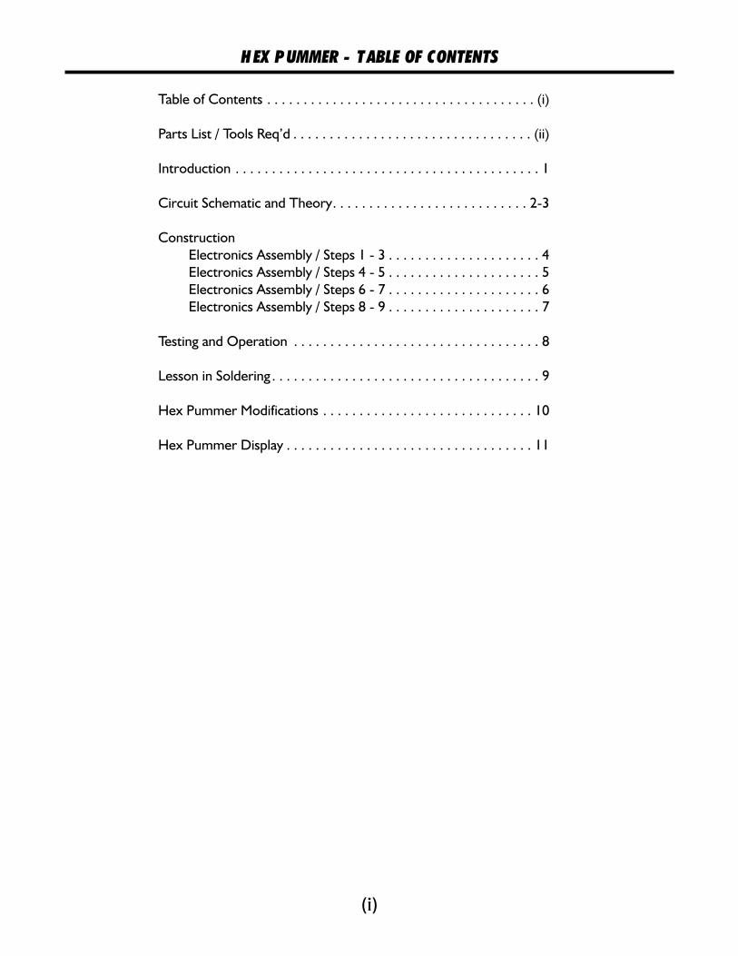
Table of Contents . . . . . . . . . . . . . . . . . . . . . . . . . . . . . . . . . . . . . (i)
Parts List / Tools Req’d . . . . . . . . . . . . . . . . . . . . . . . . . . . . . . . . . (ii)
Introduction . . . . . . . . . . . . . . . . . . . . . . . . . . . . . . . . . . . . . . . . . . 1
Circuit Schematic and Theory. . . . . . . . . . . . . . . . . . . . . . . . . . . 2-3
Construction
Electronics Assembly / Steps 1 - 3 . . . . . . . . . . . . . . . . . . . . . 4
Electronics Assembly / Steps 4 - 5 . . . . . . . . . . . . . . . . . . . . . 5
Electronics Assembly / Steps 6 - 7 . . . . . . . . . . . . . . . . . . . . . 6
Electronics Assembly / Steps 8 - 9 . . . . . . . . . . . . . . . . . . . . . 7
Testing and Operation . . . . . . . . . . . . . . . . . . . . . . . . . . . . . . . . . . 8
Lesson in Soldering . . . . . . . . . . . . . . . . . . . . . . . . . . . . . . . . . . . . . 9
Hex Pummer Modifications . . . . . . . . . . . . . . . . . . . . . . . . . . . . . 10
Hex Pummer Display . . . . . . . . . . . . . . . . . . . . . . . . . . . . . . . . . . 11

(ii)
We strongly suggest you inventory the parts in your kit to make sure you have all the parts listed. Ifanything is missing, contact Solarbotics Ltd. For replacement parts information.
Solarbotics Ltd. Is not responsible for any special, incidental, or consequential damages resultingfrom any breach of warranty, or under any legal theory, including lost profits, downtime, good-will,damage to or replacement of equipment or property, and any costs or recovering of any material orgoods associated with the assembly or use of this product. Solarbotics Ltd reserves the right tomake substitutions and changes to this product without prior notice.
Disclaimer of Liability
1 - Hexagon Shaped Hex Pummer Printed Circuit Board (PCB)4 - Clear Ultra-bright LEDs (clear, light-bulb-looking things)1 - 24x33mm Solarcell2 - ‘AAA’ Nicad Batteries1 - 74HCT240 Octal Buffer IC Chip (bug-looking thing)4 - 0.47µF Monolythic capacitors2 - 1000µF Electrolytic capacitors (can-thing with two legs coming out one side)1 - Germanium Diode (little glass thing with two leads)1 - 100k Resistor (R1) (colored Brown / Black / Yellow / Gold)4 - 1.0M Resistors (R2, R3, R5, R7) (colored Brown / Black / Green / Gold)1 - 2.2M Resistor (R8) (colored Red / Red / Green / Gold)1 - 3.6M Resistor (R6) (colored Orange / Blue / Green / Gold)1 - 4.3M Resistor (R4) (colored Yellow / Orange / Green / Gold)1 - ‘AAA’ Battery Holder1 - Length of solarcell twisted hookup wire1 - Length of stiff wire1 - Suction cup1 - Set of instructions (if you can’t find these, you’re in deep trouble - seeing that you are
reading it right now!)
- SAFETY GLASSES. We can’t stress this enough. wear safety glasses whilesoldering and working on this kit. Eye injuries ain’t worth the risk...- Soldering iron & necessary accessories (electronics solder, damp sponge, soldering iron holder)- Set of fine side-cutters or snips for trimming leads and wires- Wire strippers to prepare the solarcell wires for soldering- Glue or double-sided sticky tape for mounting the solarcell (epoxy is best; hot-glue acceptable)- Needle-nose or fine-tip pliers (or technically known as “grabber-nabbers”)- Blue-nosed, three-limbed Bolivian tiger-moth (optional)- A sense of humor. You’re in for a lot of bad jokes...
Tools Required:AT ALL TIMES
H EX P UMMER - P ARTS LIST

(1)
Just in case you’re new to the field of BEAM robotics, let’s go through the basics: BEAM is anacronym for the four fundamentals of building relatively simple robots.
iology - Steal the best ideas that mother nature has come up with so far. Can’t beat severalmillion years of development for inspiration.
lectronics - Since we can’t (easily) use biochemistry to build our devices, we’ll use simple,effective electronics to fulfill our needs. You will rarely find anything as complicated as amicroprocessor in a BEAM robot, as we strive to get the most performance out of as little silicon aspossible. You will often find a solarcell glommed onto the top of many BEAM devices, and thoughmuch less powerful than batteries, they will last for years. This gives solar-powered BEAM devicesvery long lifetimes where they won’t require you watching over their battery status.
esthetics - Just another word for “Coolness”. If it looks clean, lean, and slick, chances are that itwas well built and will last much longer than a device lacking aesthetic appeal.
echanics - Clever mechanical design of a robot can make it very effective, much more so than aclumsy design that needs additional electronics to overcome its mechanical limitations. ManyBEAM robots are often built out of “recycled technology”, otherwise known as techno-scrap (likethat broken walkman in your junk-drawer).
With that out of the way, let’s get onto the workings of the Hex Pummer.
We call this a Hex Pummer because, well, um, you see...I use it to cast evil spells on unwittingPrince and Princesses (You know, a “hex” - it’s an evil spell....aw, just forget it...). Really poor jokesaside, it’s because it’s in the shape of a hexagon, a six-sided geometric shape. We experimentedwith several shapes - squares, triangles, truncated tetrahedrons, but nothing had the sameefficiency in shape as the hexagon. If you get six of these together, you can make a “PummerPlate”. Or string them in rows, or parallel lines. Believe me, this is the coolest shape.
“Pummer” - I’ll bet that’s a word you’ve never come across before. It’s a term coined by MarkTilden (the Father of BEAM technology) to describe the action of a special type of BLIFNAR(technical term for “ linky ght or o pparent eason”). If you had to describe what this littlelight did, you say “It exhibits a rapid turn-on action followed by a moderate decay ofmillicandela output”. OR you could say “If you could hear this light, it would say ‘PUMmmmm’”.Besides, it’s much easier to refer to this as a “Pummer” than as a “Device exhibiting a rapid turn-on action ( ) followed by a moderate decay of
) millicandela output”.
Technically, we’re using what is called a pair of “Grounded Bicore Oscillators” in “charge-pump”configuration. This means we’re using one chip to power two pummers, each of which use asimple circuit arrangement to charge up power from the storage batteries to a point where they canmake the LEDs (the lights) illuminate in brilliant pulses that slowly die away. If you’ve ever listenedto a camera flash charge up, it makes a climbing, buzzing noise. Camera flashes need very highvoltages (near 300 volts!), and they use just a 6 volt source to do it. We’re doing the same thing,but in a much smaller scale.
B
E
A
M
B LI F N A Rcould
*YAWN*...stretchZzznnfzzzz...
Hex Pummer Behavior
(wake me when youfinish...
H EX P UMMER - INTRODUCTION

R2
R1
C6
(1000µF)
C5 (1000µF)R4
R3
C1
D1
LED2
LED4
LED3
LED1
C2
R6
C3 C4 R8
R7
E
Solarcell
2 x ‘AAA’ NiCad
Batteries
Note: the means “Enable Low”, which
means it turns on when it receives a zero volt signal
E
R1 sets the “dark turn-on threshold”. Decrease it if you want to turn on earlier (in more light), or increase it so it has
to be near pitch black before it activates.
R2 & R4 set how long the LEDs actually turn on; R6 & R8 set how long much time between pulses. Increase R6 & R8 if
you want slower plulses.
R3 & R7 “slave” the two sets together. Omit these if you want a more random pumm behavior.
(2)
H EX P UMMER - CIRCUIT AND THEORY

+
+
-
-
Stage 1 - Initial charge path
Stage 2 - Outputs flip polarity (+ turns to -, - turns to +)
Discharge blocked
by diode
Charge stored
across capacitor+ -
H EX P UMMER - CIRCUIT AND THEORY
(3)
The operation of this circuit is based around a common circuit arrangement called a “voltage doubler”. Thepart of the circuit in gray is the oscillator (extra output buffers used in the circuit diagram above not shown),with outputs that flip voltage polarity about every ½ second. The trick to the voltage doubler is in the diode& capacitor arrangement.
At stage 1, the oscillator output is so that the capacitor charges up through the diode. Since an unchargedcapacitor looks the same electronically as a piece of wire, the vast majority of the current flow goes to it,rather than out the output line.
When the polarities swap (stage 2), the capacitor’s charge now sits “on top” of the switched voltage outputof the oscillator, like stacking two batteries in series, plus to minus, plus to minus. And (for example) whathappens when you stack two 1.5V batteries like this? You get the voltage - 3V! With the circuit wehave here, we’re taking the approximately 2.4V from the power in the nicad batteries, and boosting themup near 4.8V.
You’ll notice that this charge-pump diagram uses a diode. In the actual circuit, this is replaced by the LEDs1 & 3, and can be easily replaced by regular diodes for just 2 LED operation.
Since there is a diode blocking the capacitor from discharging back into the oscillator, this doubled voltageis forced out the output line. In this case, the doubled voltage is pushed through a LED, which causes thebrilliant blast of light you see. If you have an oscilloscope (regular voltmeters are too slow), you canmeasure the voltage doubling yourself by measuring the voltage output at the ground side of the C5 or C6capacitor. Take out LED2/4 first, otherwise it’ll eat up the voltage before you can measure it.
twice
HexPummer1.1
HexPummer1.1
In
Out
+ C6
+ C5
R1
R5
R6
-B
AT
T+
R7
R2 R3
R4
R8
C2 C4
74HCT240
(C) Solarbotics 2000
He
xP
um
me
r1
.1
C3C1
SC
D1
LED
3
LED
1LE
D2
LED
4
In
Out
+ C6
+ C5
R1
R5
R6
-B
AT
T+
R7
R2 R3
R4
R8
C2 C4
74HCT240
(C) Solarbotics 2000
He
xP
um
me
r1
.1
C3C1
SC
D1
LED
3
LED
1LE
D2
LED
4
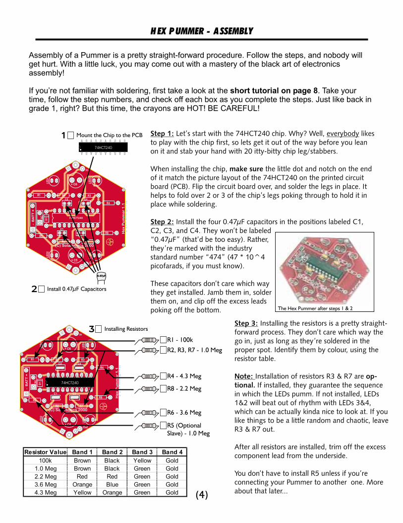
Step 3:
Note: op-tional.
Installing the resistors is a pretty straight-forward process. They don’t care which way thego in, just as long as they’re soldered in theproper spot. Identify them by colour, using theresistor table.
Installation of resistors R3 & R7 areIf installed, they guarantee the sequence
in which the LEDs pumm. If not installed, LEDs1&2 will beat out of rhythm with LEDs 3&4,which can be actually kinda nice to look at. If youlike things to be a little random and chaotic, leaveR3 & R7 out.
After all resistors are installed, trim off the excesscomponent lead from the underside.
You don’t have to install R5 unless if you’reconnecting your Pummer to another one. Moreabout that later...
(4)
H EX P UMMER - A SSEMBLY
Step 1:
Step 2:
Let’s start with the 74HCT240 chip. Why? Well, likesto play with the chip first, so lets get it out of the way before you leanon it and stab your hand with 20 itty-bitty chip leg/stabbers.
When installing the chip, the little dot and notch on the endof it match the picture layout of the 74HCT240 on the printed circuitboard (PCB). Flip the circuit board over, and solder the legs in place. Ithelps to fold over 2 or 3 of the chip’s legs poking through to hold it inplace while soldering.
Install the four 0.47µF capacitors in the positions labeled C1,C2, C3, and C4. They won’t be labeled“
everybody
make sure
0.47µF” (that’d be too easy). Rather,they’re marked with the industrystandard number “474” (47 * 10^4picofarads, if you must know).
These capacitors don’t care which waythey get installed. Jamb them in, solderthem on, and clip off the excess leadspoking off the bottom.
Mount the Chip to the PCB
Installing Resistors
Install 0.47µF Capacitors
1
3
2
0.47µF
74HCT240
Assembly of a Pummer is a pretty straight-forward procedure. Follow the steps, and nobody willget hurt. With a little luck, you may come out with a mastery of the black art of electronicsassembly!
If you’re not familiar with soldering, first take a look at the . Take yourtime, follow the step numbers, and check off each box as you complete the steps. Just like back ingrade 1, right? But this time, the crayons are HOT! BE CAREFUL!
short tutorial on page 8
The Hex Pummer after steps 1 & 2
74HCT240
R2, R3, R7 - 1.0 Meg
R1 - 100k
R4 - 4.3 Meg
R8 - 2.2 Meg
R6 - 3.6 Meg
R5 (Optional
Slave) - 1.0 Meg
Resistor Value Band 1 Band 2 Band 3 Band 4
100k Brown Black Yellow Gold
1.0 Meg Brown Black Green Gold
2.2 Meg Red Red Green Gold
3.6 Meg Orange Blue Green Gold
4.3 Meg Yellow Orange Green Gold

H EX P UMMER - A SSEMBLY (CONT’D)
Step 4: The diode you are installing here is a special type - it’s a called a“germanium” diode. This is a “deluxe” version of a diode, that lets yourPummer work longer than if just a regular diode was used.
UNLIKE the resistors, the diode does care which way it goes in. Take a closelook at it - one end of the glass cylinder has a stripe on it. This is called the“cathode” (yeah, like you really care. You just want to know which way toput it in right? Sigh... and all the work Igo through for you... <sniff>).
Bend the diode’s legs down, right closeto the glass body of the diode. Insertthe diode with the stripe on the bodymatching the stripe on the circuit board.Now, the holes may be a little close, sodon’t use too much force to put it in -you don’t want to break it!
Step 5: Now it’s time to install the LEDs (the ight mitting iodes). Thisrequires a bit of attention to how they go in - LEDs don’t operate when putin backwards. Take a close look at the collar around the edge of the LED.You’ll see a flat spot near one of the legs. This is the “cathode” (I’ll bet youstill don’t care about cathodes...), and place it on the circuit board so itmatches the flat spot on the LED symbol on the circuit board. Repeat thisfour times at the places marked “LED1” through “LED4”.
Mount them on the of the circuit board. Theother side is what will be the front, where you will want to see the lightsblinks!
Your Pummer kit may come with LEDs of different colours. In general, theLEDs may be red, green, orange, or yellow, but since they’re called “water-clear”, you won’t know until you light the LEDs up. find out byconnecting them directly to a battery! Ifyou know what the colour is,charge up one of the 1000µF capacitorswith one or two 1.5V batteries (connectit for about 1 second), then touch theLED legs to the capacitor legs - LEDcathode to the capacitor leg nearest thestripe mark on it’s body. It will pulsequickly and die. You remember how totell which LED leg is the cathode, don’tyou?
L E D
IMPORTANT: OTHER SIDE
DO NOT
MUST
�
Install the Diode at postion ‘D1’
Note flat mark goes
near LED text, ON
OTHER SIDE!
Install LEDs
on OTHER SIDE!
4
5b
5a
HexPummer1.1
In
Out
+ C6
+ C5
R1
R5
R6
-B
AT
T+
R7
R2 R3
R4
R8
C2 C4
74HCT240
(C) Solarbotics 2000
He
xP
um
me
r1
.1C3C1
SC
D1
LED
3
LED
1LE
D2
LED
4
74HCT240
HexPummer1.1
In
Out
+ C6
+ C5
R1
R5
R6
-B
AT
T+
R7
R2 R3
R4
R8
C2 C4
74HCT240
(C) Solarbotics 2000
He
xP
um
me
r1
.1
C3C1
SC
D1
LED
3
LED
1LE
D2
LED
4
74HCT240
The diode installation
LEDs installed on UNDERSIDE of Circuit BoardCloseup of LED installation
(5)

H EX P UMMER - A SSEMBLY (CONT’D)
HexPummer1.1
In
Out
+ C6
+ C5
R1
R5
R6
-B
AT
T+
R7
R2 R3
R4
R8
C2 C4
74HCT240
© Solarbotics 2000H
ex
Pu
mm
er
1.1
C3C1
SC
D1
LED
3
LED
1LE
D2
LED
474HCT240
Install the
main capacitors61
000uF
1000uF
Installing the power capacitors C5 capacitor installation
Step 6: Time for the main power storage capacitors. These hold thecharge-pumped power, and release them in a burst to the LEDs, giving
them their blast of light. These capacitors are polarity sensitive - puttingthem in backwards is a no-no!
Identify the negative leg of the capacitor by the stripe on the body of the capacitor.Alternately, the leg is the leg. Anyways, put the capacitor in with the leg through the holenearest the in positions C4 and C5.
Do this for the top and bottom capacitors, and snip off the excess lead from underneath.
longer positive longer‘+’,
Step 7: The solarcell is the most fragile part of your Pummer.Now, it’s not “Potato-Chip” fragile, but let’s just say youshouldn’t use it to scrape the scum off your bathroom tile,ok?
Find the twisted-pair wire(black & red) and strip offthe ends so a bit of wire isexposed. I mean just a bit,like 3~5mm (that’s about1/8” ~1/4” to our ‘mericanfriends). Solder these endsto the solarcell,
Be careful with this set of solder connections, as you can easily burn thepad off the solarcell. Best is to use just a bit of solder and be quick with thesoldering iron.
When you’re done, I mean it.Do it now! If I find out you’ve accidently ripped the whole fragile solderpad offthe solarcell because you didn’t glue it down....well, I won’t be impressed.
After you have the wires attached to the solarcell, you can strip and solder theother ends to the pads in the box labeled “SC” (for “Solar Cell” - clever, eh?).Again, red to positive (+). SOLDER THESE WIRES TO THE PADS ON THE SIDE. It’snot an absolute necessity, but it will make mounting your solarcell easier, as the other side is where it will be!
If you want to make your installation a bit neater, trim the wire back so it just pokes out about 2cm (about 3/4”)from the solarcell before soldering it on. it’ll mount much cleaner to the circuit board when you glue the solarcelldown.
black tonegative (-), red to posi-
tive (+).
glue the wire down to the back of the solarcell.
OTHERblack to negative (-),
HexPummer1.1
In
Out
+ C6
+ C5
R1
R5
R6
-B
AT
T+
R7
R2 R3
R4
R8
C2 C4
74HCT240
(C) Solarbotics 2000
He
xP
um
me
r1
.1
C3C1
SC
D1
LED
3
LED
1LE
D2
LED
4
74HCT240
Solarcell installation
Panasonic
BP-2433
Install the
solarcell
GLUE
7
Solarcell installation closeup
NOTE:
SOLDER TO THESE PADS
ON SIDE!OTHER
(6)

H EX P UMMER - A SSEMBLY (CONT’D)
HexPummer1.1
HexPummer1.1
In
Out
+ C6
+ C5
R1
R5
R6
-B
AT
T+
R7
R2 R3
R4
R8
C2 C4
74HCT240
© Solarbotics 2000
He
xP
um
me
r1
.1
C3C1
SC
D1
LED
3
LED
1LE
D2
LED
4
In
Out
+ C6
+ C5
R1
R5
R6
-B
AT
T+
R7
R2 R3
R4
R8
C2 C4
74HCT240
© Solarbotics 2000
He
xP
um
me
r1
.1
C3C1
SC
D1
LED
3
LED
1LE
D2
LED
4
74HCT240
74HCT240
Install the
battery holder
Install the
batteries
8
9
Battery holder installation closeup
Step 8: Slap that bad-boy battery holderdown in the only place it’ll fit - theposition labeled ‘BATT’ (clever, theselabels, eh?). Install it so that it sitsdirectly down on top of the 74HCT240chip, then solder it in place (flip thewhole thing over to solder).
These battery-holder leads are prettystrong, and will be the only support theyneed. If you wish, you can glue theholder to the ‘240 chip for additionalsupport later.
Step 9: Now for the question of thecentury: what do you put in a batteryholder? (”Ummm... turkey leftovers?”)
(sigh...)
Take your rechargeable batteries andstick them in the way the holder haslabeled.
Step 10: that your Pummer is showing signs of life, the only thingleft to do now is to glue down your solarcell to the other side of the PCB. Wepersonally like double-sided foam sticky-tape, but epoxy or hot-glue works wellin a pinch.
Alternately, you can use a stiffer wire for your solarcell attachments, and makeit do double-duty as an adjustable solarcell-holder. A bit harder to work with,but if you want that solarcell pointing someplace else other than straight up,this answer works well.
Assuming
Battery-holder installation
The battery installation
(7)

H EX P UMMER - TESTING & O PERATION
Your Hex Pummer is now officially complete. Great. You’ve put the batteries in; what? Well, ifyour batteries arrived with any sort of charge, you should be able to cover up the solarcell, and seethe LEDs start to operate. Nothing happening? Try standing in a closet. Still nothing? Are youstanding in the closet your Pummer? Leave the closet, and go get the Hex Pummer, andtry again!
If your device isn’t operating after finishing assembly, you’ll most likely have batteries that need tocharge up. A quick charge in sunlight or under a halogen or incandescent lamp 30cm away (1 foot)for about a ½ hour should give you some results. If you aren’t that patient, you can even use(gasp!) regular AAA batteries to power it up. Regular batteries will run this device for many days,up to weeks at a time (but of course, they won’t recharge). Remember, you have to trick the HexPummer into believing it’s dark - cover the solarcell to test the operation.
If your device fails to cooperate, recheck your installation. LED 1 & 2 work together, as do LED3 & 4, so if either one of the LEDs in each pair are wrong, that pair will fail totally. Also make sureyour solder job is neat, tidy, and clean of flux. If you are using water-soluable flux (like the Hydro-Xsolder we sell), you wash off your circuit board. Use some hot water and an old toothbrush toclean the flux-gunk out from between the solder joints, top and bottom. Then blow out the waterunder the chip, and leave it dry (hey - why not under a nice, warm, nicad-recharging light?).
Like any other Nicad battery, they like to go through complete charge/discharge cycles.Fortunately, the Hex Pummer (for the most part) does exactly this. It take approximately four hoursof direct sunlight for the batteries to fully charge. That means even if you place your Hex Pummerin a location where it getsonly reflected light, or seesonly overcast daylight, it willmost likely store up enoughenergy to Pumm when itgets dark.
The great thing about theHex Pummer design is thatit uses practically anyamount of energy to Pummthe LEDs to some degree.Even on a very weakcharge, you can still see theLEDs weakly doing theirPumm-thing. In truth, youwill see the most intenseoperation during the firsthour of operation, which willslowly decrease in intensityfor the remainder of thenight.
now
without
still
must
Hex Pummer 3-Day Operation
1.5
1.7
1.9
2.1
2.3
2.5
2.7
12
:41
AM
2:3
5A
M
4:2
9A
M
6:2
3A
M
8:1
7A
M
10
:11
AM
12
:05
PM
1:5
9P
M
3:5
3P
M
5:4
7P
M
7:4
1P
M
9:3
5P
M
11:2
9P
M
1:2
3A
M
2:1
7A
M
4:1
1A
M
6:0
5A
M
7:5
9A
M
9:5
3A
M
11:4
7A
M
1:4
1P
M
3:3
5P
M
5:2
9P
M
7:2
3P
M
9:1
7P
M
11:1
1P
M
1:0
5A
M
2:5
9A
M
4:5
3A
M
6:4
7A
M
8:4
1A
M
10
:35
AM
12
:29
PM
2:2
3P
M
4:1
7P
M
6:1
1P
M
8:0
5P
M
9:5
9P
M
11:5
3P
M
1:3
7A
M
3:3
1A
M
Time
Vo
lts
Activation:
6:33pm
Activation:
5:17pm
Activation:
5:27pm
Recharge
starts at:
8:11am
Recharge
starts at:
7:11am
Recharge
starts at:
7:15am
(8)(8)

H EX P UMMER - LESSON IN SOLDERING
One of the most common errors is to accidently "bridge" the pads betweencomponents. Make sure that there aren't any tiny flecks of solder or wirebetween the pads.
Soldering! If you have never soldered before, it could bean intimidating concept. After all, you’re being asked to takea scalding-hot piece of metal, and use it to metal ontodelicate electronic components!
It is actually a pretty straight-forward process. We’ve taught8-year old kids to solder (with supervision), so there’s noreason why can’t wrap your head around this skill.
The trick is heat. Heat is good. Too often, new students arescared by the concept of all this heat in a small space. Well,what is really hot to you and me (the soldering iron), isactually just a sunny day at the beach for the components.
A successful solder connection can almost be guaranteed ifyou remember you are heating pieces of metal, not justone. Here’s the basic procedure:
1) Put the component leg through the solder pad hole (snugged up close)
2) Wipe off the tip of the soldering iron on a damp sponge so it’s shiny and clean. It transfers heat betterwhen it’s clean.
2) Holding the soldering iron like a pencil at the tip! Hot metal, remember?), jam the tip into thecorner where the leg comes through the hole. This means the soldering iron tip is heating the leg
the solder pad.
3) Count to 4. This heats up the parts.
4) While add solder to the of the leg. At this point, both theleg and pad will be hot enough that they will melt the solder into a nice connection. You’ll probably noticesome yellow or clear goop appear when you solder. Don’t worry, this is and it is in the solder to helpmake a good, clean connection.
Do treat the soldering iron like a brush. That is, melt solder to the tip, and then try to smearit onto the connection. You’re a electronics enthusiast, not a painter!
If you mess up, don’t worry. You can reheat the solder andbang it loose with a quick snap onto a pad of paper( use eye protection at all times). If you get twosolder pads fused together, use the soldering iron like apen, and “draw” a line between the pads. The solder willremelt, and flow off to the sides.
The final check for any solder joint is the “wiggle test”.Firmly grip each component and gently rock it side-to-side. movement of the component legs on the otherside of the board means the joint isn’t firm, no matter howgood it Reheat and apply more solder to the joint.
melt
you
two
(notboth
keeping the soldering iron in place, other side
flux,
please
Any
looks.
and
NOT DON’T
Solder
Soldering Iron(hold here!)Solder Pad
Circuit Board
Component Leg
1. Insert component
2. Wipe soldering iron tip on damp sponge
3. Stick iron tip into corner of leg & pad
4. Count to 4
5. Add solder
6. Remove iron
Solder flecks
PN
22
22
BadNo flow from leg to pad
GoodFlows from leg to pad
BadSolder “bridge” across pads
Bad & Good Solder Joints
X
X
�
(9)

H EX P UMMER - M ODIFICATIONS
2 LED Operation - Now, why would you want to run only two of thefour LEDs? Well, two take half as much power. That means you’llget much brighter Pummers running for longer than if all four werein operation.
If you want to convert your Hex Pummer into dual-LED operation,you simply the LEDs at positions LED1 and LED3 withdiodes (diode bar closest the flat spot on the LED picture). Regular1N914 or 1N4148 silicon diodes (the most common types) will workjust fine, but you will get a more performance if you can use“germanium” type diodes (1N34). They’re somewhat more expensive (around $1 each), but if you wantto squeeze every last erg of energy out of your Hex Pummer, that’s what you want to use.
replace
little
Slaving Operation - If you happen to have more than one Hex Pummer, you can connect them to-gether and get the lights operate in sequence. Rather than having a collection of LEDs firing off atrandom times, you can have a smooth series of Pumms acrossseveral Hex Pummers. In theory, there is no limit to how many youcan link up, or what shape you can build with your Hex Pummers.
Remember resistor pad R5? We didn’t install anything there duringassembly, as it’s only needed for slaving one Hex Pummer to an-other. If you are going to now slave two together, you have to installthat 1.0 Meg resistor on of the pummers.
You have a ‘Master’ Hex Pummer that sets the beat for all the ‘Slave’Pummers that follow it. Each of the slaves need this resistor installedat position R5.
Once you have soldered in the slaving R5 resistor, you can now linkup the master to the slave.
Simply make an electrical connec-tion from one square pad on one Hex Pummer to the square pad onthe other Hex Pummer. This connects the “ground” lines, which givethe two devices a common voltage reference point. In the picture, theground is soldered to the wire that is actually tying the two Pummerstogether.
Just run a wire from the pad labeled “Out” onthe master to the pad “In” on the slave. That’s it! Now your Pummersare set up to coordinate the sequence they now activate their LEDs!
one
1) Voltage Ground Connection:
2) Signal Connection:
HexPumm
In
+ C6
R1
BA
TT
+
R2 R3
R4
C2 C4
74HCT240
um
me
r1
.1
SC
D1
LED
3
LED
1
74HCT240
Diodes instead of LEDs for 2-LED operation
Installing the R5 slave resistor (1meg)
Connecting master (top) to slave (bottom)
Diodes
(10)

Outdoor-facing & Indoor-facing Hex Pummers
H EX P UMMER - D ISPLAY
Inwards-facing LEDs
Outwards facing LEDs
4: Make hook loop
1: Suction cup & wire
3: Twist wire snug & secure
2: Wrap the wire around the cups groove
Your Hex Pummer is now complete - now what do you do with it? Well, putting it on display is alwaysa good idea. Do with it what you will - put it on your car rear dashboard (put blue LEDs in it - makestraffic line up behind you for miles!), hang it in your window, dangle it from your pets collar...I won’t tellanyone.
Here’s some basic technique you can useto display your Hex Pummer. Feel free toexpand on the concept!
Now that you’ve made the hook, how areyou going to hang it? Of course, thesolarcell has to face in the direction it getsthe most light, but do you want the lightsfacing inwards or outwards?
Facing outwards is easy - just hang thepummer so both the solarcell and LEDspoint towards the great outdoors.
Facing inwards requires a bit more work, asyou want the solarcell pointing towards thebest light source. The answer? Flip the sidethe solarcell is on! Just glue the solarcelldown to the top of the battery holder,leaving the face with all the purrrrdy lightsfacing inwards.
Hex Pummer free-standing
(11)

For kits, parts and further technical support, contact us at:Solarbotics Ltd.
179 Harvest Glen Way NE, Calgary, Alberta, Canada T3K 4J4Ph: (403) 818-3374 (Mon-Fri, 9am-6pm MST), Fax: (403) 226-3741
[email protected] / www.solarbotics.com