the beaufort gyre observing system 2004: mooring … · wire rope and hardware must be incorporated...
TRANSCRIPT
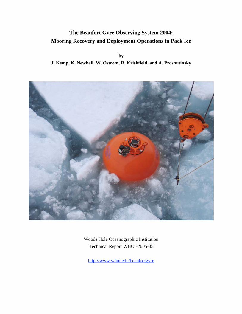
The Beaufort Gyre Observing System 2004:
Mooring Recovery and Deployment Operations in Pack Ice
by
J. Kemp, K. Newhall, W. Ostrom, R. Krishfield, and A. Proshutinsky
Woods Hole Oceanographic Institution
Technical Report WHOI-2005-05
http://www.whoi.edu/beaufortgyre

1
Abstract
Situated beneath the Arctic perennial ice pack, the principal components of the
Beaufort Gyre Observing System are three deep-ocean bottom-tethered moorings with
CTD and velocity profilers, upward looking sonars for ice draft measurements, and
bottom pressure recorders. A major goal of this project is to investigate basin-scale
mechanisms regulating freshwater and heat content in the Arctic Ocean and particularly
in the Beaufort Gyre throughout several complete annual cycles. The methods of
recovering and re-deploying the 3800 m long instrumented moorings from the Canadian
Coast Guard Icebreaker Louis S. St. Laurent in August 2004 are described.
In ice-covered regions, deployments must be conducted anchor-first, so heavier
wire rope and hardware must be incorporated into the mooring design. Backup buoyancy
at the bottom of the mooring is advised for backup recovery should intermediate lengths
of the mooring system get tangled under ice floes during recovery. An accurate acoustic
survey to determine the exact location of the mooring, adequate ice conditions, and
skilled ship maneuvering are all essential requirements for a successful mooring
recovery. Windlass (or capstan) procedures could be used for the recovery, but a traction
winch arrangement is recommended.

2
Project Overview
The Beaufort Gyre has been characterized in the past as the region of “relative
inaccessibility” in the Arctic Ocean because of the difficulty of accessing the area by
icebreaker due to heavy ice conditions and by airplane due to its remoteness from the
mainland. As a result, the area is one of the most poorly sampled regions in the Arctic
Ocean. In 2002, the National Science Foundation (NSF) Office of Polar Programs
recognized the great importance of the Beaufort Gyre in the fresh water balance of the
Arctic Ocean and funded the “Beaufort Gyre Freshwater Experiment (BGFE): Study of
fresh water accumulation and release mechanism and a role of fresh water in Arctic
climate variability” (Principal Investigator, Andrey Proshutinsky). The major goal of this
project was to investigate basin-scale mechanisms regulating freshwater content in the
Arctic Ocean and particularly in the Beaufort Gyre throughout a complete annual cycle.
As part of the field experiment for this project, three bottom-tethered moorings were
deployed with CTD and velocity profilers, upward looking sonars for ice draft
measurements, and bottom pressure recorders, and four expendable surface buoys with
CTDs during a Joint Western Arctic Climate Study (JWACS) cruise on the Canadian
Coast Guard Icebreaker Louis S. St. Laurent (LSL) in August 2003 (Ostrom et al., 2004).
However, given the importance of this region for Arctic climate studies, it was
desired to investigate interannual and longer variability, so that it was necessary to
continue acquiring the same data for several years, although the observational program
supported by NSF would end with recovery of the moorings in 2004. In 2004, WHOI’s
Ocean and Climate Change Institute provided the support to redeploy the three moorings
in order to continue monitoring freshwater and heat content in this climatically sensitive
region of the Arctic Ocean, thus establishing the Beaufort Gyre Observing System
(BGOS).
In August 2004, the sites were revisited, the moorings were recovered, data were
retrieved from the instruments, the hardware and sensors were refurbished, and the
systems were redeployed at the same locations again from the LSL during a JWACS
cruise (Figure 1). In addition, a prototype Ice-Tethered Profiler (ITP) buoy was deployed
in combination with an Ice Mass Balance (IMB) buoy. The times and locations of the

3
recovery and deployment operations are given in Table 1. More information on the
BGFE/BGOS project, including the scientific motivation, publications, descriptions of
methods (instruments and modelling), field operations (including dispatches from each of
the cruises), historical and acquired data, and a “History of Arctic Exploration and
Scientific Discovery” are available at http://www.whoi.edu/beaufortgyre.
Figure 1: JWACS 2004 cruise track (Figure by Sarah Zimmermann), with BGOS
mooring locations (stars), and ITP/IMB deployment location (inverted triangle).
B
C
A

4
In 2004, NSF granted a 5-year proposal “The Beaufort Gyre System: Flywheel of
the Arctic Climate?” so that all the moorings that are recovered in 2005 with support of
the WHOI Ocean and Climate Change Institute, will be maintained until 2008 with NSF
support and investigation of the Beaufort Gyre system will continue.
Table 1: Summary of BGFE/BGOS 2004 field operations.
Mooring Water 2003 2004 2004 2004
Designation Depth (m) Location Recovery Deployment Location
BGFE-A 3824 75° 00.39'N 10-Aug 12-Aug 75° 00.242' N
149° 58.752'W 14:34 UTC 19:58 UTC 149° 57.742'W
BGFE-B 3821 78° 01.491'N 15-Aug 17-Aug 78° 00.967'N
149° 49.378'W 13:23 UTC 17:59 UTC 149° 51.544'W
BGFE-C 3722 76° 59.254'N 20-Aug 22-Aug 76° 59.457'N
139° 54.229'W 18:57 UTC 19:31 UTC 139° 58.407'W
ITP & IMB 19-Aug 77° 10.4'N
(buoy location is ship's position ~500 m from site) 15:00 UTC 141° 13.0'W
Mooring Design
The bottom-tethered moorings which were deployed in 2003 are described
thoroughly in Ostrom et al. (2003). Briefly, each mooring consists of a top sphere
providing 2500 lb of buoyancy and housing an Upward Looking Sonar (ULS) and
Benthos transponder. The length of each mooring was individually adjusted so that the
top sphere would be located at 45 m, however only one of the three moorings actually
ended up close to the correct depth while the other two ended up deeper than intended
due to uncertainties in the bottom depth and incorrect wire lengths. The ULS acquires ice
draft data, while the transponder is used for remotely determining the location of the
mooring by performing an acoustic survey.

5
Figure 2: BGOS mooring schematic as deployed in 2004.

6
Below the top sphere and chain bridle, a 2000 m segment of wire rope supports a
McLane Moored Profiler (MMP), which acquires seawater temperature, salinity and
velocity profiles approximately twice every two days between about 50 and 2000 m.
Where the upper sphere was deeper than intended, the upper limit of the MMP is also
deeper. Below the MMP, various wire rope segments and glass floats were distributed to
fill in the mooring length, reduce tension on the wire during deployment, and provide
backup buoyancy for recovery.
On one mooring (A), a McLane Research sediment trap was installed at 3000 m
depth for a biogeochemical particle flux study. At the bottom of each mooring is a 3800
lb anchor, with mount for a Bottom Pressure Recorder (BPR) to measure the pressure of
the entire water column. The BPR is attached to a set of dual releases which are
suspended above the anchor. Triggering one of the two releases with an acoustic pulse
causes the entire system (except anchor) to float to the surface where it can be recovered.
On all the moorings, the glass flotation spheres were redistributed differently
along the mooring in 2004 compared to 2003, in order to reduce tangling of the wire on
recovery. A schematic of the BGFE mooring design as redeployed in 2004 is presented
in Figure 1.
Methods
The method of deploying and recovering bottom-tethered moored instruments in
Arctic ice-covered waters from air supported landings and using divers for recovery was
described by Aagaard et al. (1978). Before icebreaker vessels were able to regularly
penetrate the perennial ice pack, these air supported operations (also employed by
Institute of Ocean Sciences (IOS), Canada) provided the only means to regularly revisit
moored sites, and are still utilized today for annual maintenance of North Pole
Environmental Observatory systems (http://psc.apl.washington.edu/northpole). In this
technical report, we describe the methods of recovering and re-deploying instrumented
deep-ocean bottom-tethered moorings within the Arctic perennial ice pack from
icebreakers without diver assistance.
7
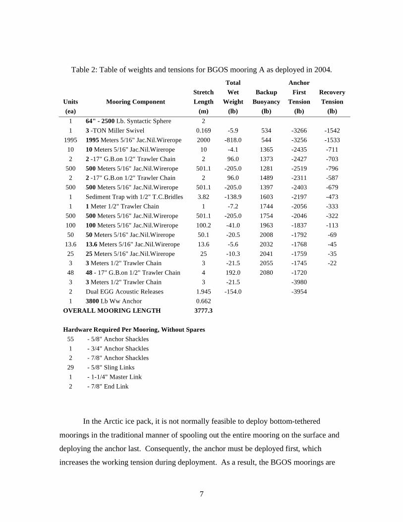
Table 2: Table of weights and tensions for BGOS mooring A as deployed in 2004.
Units Mooring Component
Stretch
Length
Total
Wet
Weight
Backup
Buoyancy
Anchor
First
Tension
Recovery
Tension
(ea) (m) (lb) (lb) (lb) (lb)
1 64" - 2500 Lb. Syntactic Sphere 2
1 3 -TON Miller Swivel 0.169 -5.9 534 -3266 -1542
1995 1995 Meters 5/16" Jac.Nil.Wirerope 2000 -818.0 544 -3256 -1533
10 10 Meters 5/16" Jac.Nil.Wirerope 10 -4.1 1365 -2435 -711
2 2 -17" G.B.on 1/2" Trawler Chain 2 96.0 1373 -2427 -703
500 500 Meters 5/16" Jac.Nil.Wirerope 501.1 -205.0 1281 -2519 -796
2 2 -17" G.B.on 1/2" Trawler Chain 2 96.0 1489 -2311 -587
500 500 Meters 5/16" Jac.Nil.Wirerope 501.1 -205.0 1397 -2403 -679
1 Sediment Trap with 1/2" T.C.Bridles 3.82 -138.9 1603 -2197 -473
1 1 Meter 1/2" Trawler Chain 1 -7.2 1744 -2056 -333
500 500 Meters 5/16" Jac.Nil.Wirerope 501.1 -205.0 1754 -2046 -322
100 100 Meters 5/16" Jac.Nil.Wirerope 100.2 -41.0 1963 -1837 -113
50 50 Meters 5/16" Jac.Nil.Wirerope 50.1 -20.5 2008 -1792 -69
13.6 13.6 Meters 5/16" Jac.Nil.Wirerope 13.6 -5.6 2032 -1768 -45
25 25 Meters 5/16" Jac.Nil.Wirerope 25 -10.3 2041 -1759 -35
3 3 Meters 1/2" Trawler Chain 3 -21.5 2055 -1745 -22
48 48 - 17" G.B.on 1/2" Trawler Chain 4 192.0 2080 -1720
3 3 Meters 1/2" Trawler Chain 3 -21.5 -3980
2 Dual EGG Acoustic Releases 1.945 -154.0 -3954
1 3800 Lb Ww Anchor 0.662
OVERALL MOORING LENGTH 3777.3
Hardware Required Per Mooring, Without Spares
55 - 5/8" Anchor Shackles
1 - 3/4" Anchor Shackles
2 - 7/8" Anchor Shackles
29 - 5/8" Sling Links
1 - 1-1/4" Master Link
2 - 7/8" End Link
In the Arctic ice pack, it is not normally feasible to deploy bottom-tethered
moorings in the traditional manner of spooling out the entire mooring on the surface and
deploying the anchor last. Consequently, the anchor must be deployed first, which
increases the working tension during deployment. As a result, the BGOS moorings are
8
designed with: 1) heavier gauge wire rope (5/16”) for increased strength, and 2) backup
flotation at the bottom to allow for the entire mooring to be recovered if the mooring
parts during deployment (or anytime prior to recovery). The backup buoyancy also
allows the mooring to be recovered from the bottom end if the upper mooring becomes
tangled in ice floes during recovery.
Table 2 lists the design weights, lengths and buoyancies of mooring A as
deployed in 2004, and estimated tensions during deployment and recovery. Note that the
minimum backup buoyancy at any time during deployment is always greater than 500 lb.
Static tension varies from as much as 4000 lb to as little as 1700 lb during the
deployment as each item of equipment and flotation are attached. Tension during
recovery is always less than 1600 lb.
Recovery Platform – CCGS Louis S. St. Laurent
Unlike most mooring operations conducted on UNOLS vessels where the
mooring deployment and recoveries are performed from the stern of the vessel, mooring
operations on the LSL are conducted from the foredeck of the ship. The work area is
equipped with a starboard side A-frame and two stiff boom cranes located on either side
of the foredeck, each capable of lifting heavy gear out of the water. The deployment
cruise on the LSL in 2003 utilized the ships windlass to deploy the BGOS moorings, but
this technique proved to be rather slow and labor intensive, and would be more so during
recovery operations. Consequently, a special traction mooring winch system
(manufactured by the Lebus company in England) and custom fairlead plate were
installed on the ship for use in conjunction with the ship’s cranes and A-frame in the
recovery and re-deployment of the moorings in 2004 (Figure 3).
Traction Winch
The Lebus traction winch system consists of three primary components: the
double barreled capstan, spooler winch and power pack. The function of the winch
system allows mooring wires and ropes to be deployed and recovered utilizing a double

9
headed capstan acting as a traction winch in conjunction with a tension spooling winch
that provides constant back tension on the mooring wire and supports individual wire and
rope mooring segments reels.
The double barreled capstan is the load bearing or hauling segment of the winch
system (high tension component), and the spooler winch is the mooring wire and rope
delivery system (low tension component). In haul mode, this system operates by the
capstan winch pulling the mooring wire (with constant tension) from the spooler winch.
Figure 3. The Lebus traction winch system installed on the fore deck of the LSL:
a) double barreled capstan, b) spooler winch, c) power pack, d) fairlead plate and
block, e) remote control box.
The capstan winch has two capstan barrels positioned horizontally one over the
other. There are two fair lead gates located at the front and rear of the winch through
a
b
c
d
e
10
which the mooring wire enters and exits. The free end of the mooring wire is guided
through the front fairlead gate (low tension side), wound around the two capstan barrels
with typically 5 to 6 wraps, and passed out through the rear fair lead gate (high tension
side). The axial ordination of the upper barrel is important in maintaining adequate
separation between the wire wraps. The separation between each wrap can be adjusted by
activating a manual hydraulic control pump that pivots the upper capstan barrel
horizontally, causing the wire wraps to migrate towards the desired inner or outer edge of
the barrels. The capstan winch is operated from a remote control box. This control box is
fitted with an emergency stop button and a toggle control that allows the capstan barrels
to operate at infinite speeds. The winch’s operating capacity is 7000 lb at 30 fpm.
The spooler winch is a hydraulically powered reel stand that is controlled
separately from the capstan winch. This winch is designed to support wooden wire and
rope storage reels and to provide a haul in line tension up to 250 lb. The spooler winch
should nominally maintain between 125 to 150 lb of back tension in order to keep the
wraps tight on the capstan barrels. The spooler is generally positioned approximately 10
ft from the low tension side of the capstan winch. This is to allow for adequate working
area between the two pieces of equipment in order to connect and disconnect wire and
rope mooring segments. The capstan and spooler winches are powered by a 400 volt, 3-
phase, 60Hz electric hydraulic power pack.
Traditionally, moorings winches have been configured with single large drums.
All of the mooring wire and rope shots are pre–wound for deployment and off spooled
following a mooring recovery from a single drum. The Lebus winch system saves
substantial ship time by not having to handle the mooring wire twice. These components
can be compressed and fouled on a single drum due to high mooring tensions and are
often damaged from kinking. Mooring wire and ropes that are recovered and wound onto
wooden storage reels are undamaged because of the Lebus spooler winch’s low hauling
tensions, making it possible to redeploy these components.
The Lebus winch system requires three personnel that are thoroughly trained in
the winch’s operation and have a familiarity with the mooring components that are going
to be deployed or hauled. These technicians are the capstan, slew and spooler operators.

11
The capstan operator must have a clear understanding of the following points:
a. The double barreled capstan has a greater line pull than the spooler winch.
b. The double barreled capstan has in most cases has a hauling potential that
could break the mooring wire or rope.
c. The capstan winch will hold the load only as long as there is an opposing
minimum load of 125 lb on the low tension side of the winch.
The capstan operator’s responsibilities entail the following:
a. Controlling the speed and direction of haul in and pay out of the mooring
wire.
b. Ensuring that the capstan winch’s fair lead gates are positioned correctly.
c. Verifying that personnel are clear of the rotating capstan barrels.
The slew operator’s working area is between the capstan winch and the spooling
winch. This operator’s responsibility is to keep constant observation of the wire or rope
wraps that are bent around the capstan barrels and adjusting the axial angle of the upper
capstan barrel so that the wraps are equally spaced. In addition, the slew operator’s
responsibilities include:
a. Monitoring the retarded tension from the spooler winch.
b. Confirming that the correct mooring components are being passed around the
capstan winch.
c. Opening and closing the low tension gate.
d. During mooring pay out, ensuring that all hardware terminations are wrapped
prior to passing around the capstan winch.
e. Securing a stopper line to the loose end of a deployed mooring wire during
reel changes.
12
The spooler operator should be efficient in reel transfer operations and be familiar
with the mooring components to be used in the mooring. The spooler operator’s
responsibilities include the following:
a. Checking that the correct mooring wire or rope segment is on the winch.
b. That the storage reel secured to the winch has been shafted correctly, in order
to prevent the reel from coming lose from the winch drive pin spinning free
causing uncontrolled mooring wire slack on the capstan drums.
c. Verifying that personnel are clear of the spooler winch prior to capstan
operator starting payout or hauling in.
d. Keeping the line in setting on the spooler winch high enough to provide
adequate back tension on the mooring wire or rope against the capstan drums
to prevent slippage.
e. The spooler operator must never shift the winch into the pay out or neutral
mode while there is a load on the high tension side of the capstan winch.
Precision Survey
During the time that a mooring system falls to the seafloor when deployed, it is
subject to some drift along the way due to currents and wire angle. This is especially true
for anchor last deployments where the mooring system is stretched out horizontally
during the operation, so that the system will typically fall around 15% of length of the
mooring away from the anchor drop site. For anchor first deployments, this effect is
much less since the mooring is already stretched out vertically, and the anchor has less
distance to fall. The BGFE/BGOS moorings were designed for the top float to be only 50
m from the surface when installed, and were deployed anchor first, so that anchor would
only have to drop less than 100 m when let go during the deployment. Consequently, it
was expected that the locations where the moorings were let go during deployment would
be very close to the locations where the anchors were actually positioned.
However, for recovery operations in sea ice, it is extremely important to know the
exact location of the mooring, so the system is not released under ice floes, but rather in

13
open water areas. Therefore, a close range acoustic survey on transponders mounted on
the mooring was performed prior to each recovery operation. Basically, the survey
consists of measuring slant range response times of acoustic pulses from a transponder on
the mooring from several different locations around the expected mooring site, and
determining the intersection of the circles.
The survey begins by selecting a location near (typically within 1 km) of the
mooring site and hanging an acoustic transducer over the side of ship, between 5 to 10 m
below the sea surface. Markings on the transducer cable may be used to facilitate
determining the actual depth of the transducer, which is needed for the calculations. On
the BGOS moorings, Benthos transponders are mounted on the top flotation spheres for
survey purposes, but the Edgetech acoustic releases at the bottom of the mooring could
also be used as transponders for the survey. Using the transducer deck unit (in our case
an Edgetech model 8011), an interrogate frequency pulse is sent to the transponder,
which responds with a reply frequency pulse. The time between pulses (travel time) is
measured by the accurate time clock in the deck unit, and displayed (or may be recorded
digitally). Simultaneously, the location of the survey point must be recorded.
Ideally, the location of the survey point is the exact location where the interrogate
transducer is positioned. Here, we obtained GPS locations from the ship’s bridge, so that
there was some offset (on the order of 20-30 m) between the recorded and actual
transducer locations. This discrepancy will result in some error in the measured travel
time, and will generally reduce the precision of the triangulated mooring location.
An acoustic survey software program developed at WHOI by Arthur Newhall is
used to perform the calculations for determining the actual mooring location using a least
squares estimation algorithm on the intersection of the data from the survey points. In
addition to the survey point response times, the program requires entries for the depth of
the shipboard transducer, depth of the mooring transponder and speed of sound of the
seawater; sound speed profiles were obtained from a CTD cast. On the BGOS moorings,
the transponders were between 50 and 80 m deep, and the mean speed of sound in the
upper layer was approximately 1460 m/s.

14
Using the travel times (which are slant times between the transducer and the
transponder), depths, and speed of sound, the slant times are converted into horizontal
ranges which are plotted as circles around the respective survey locations. The least
squares estimate of the intersection determines the actual mooring location. The
estimates used for the speed of sound and transponder depths can be adjusted to improve
the intersection of the circles. Sometimes survey locations too close to the mooring site
can produce erroneous circles, probably because the return time is too quick for the deck
unit so that it detects reflections.
Figure 4. Survey plot for mooring B.
15
Uncertainties associated with the location, speed of sound, and transponder depths
added up to an apparent error of approximately 20 m in the range of any single survey
point. However, by taking multiple survey points, the statistical error of the triangulated
estimate is reduced. The error in the location was the largest contributing factor, and
could be reduced by obtaining location directly over the shipboard transducer using a
hand-held GPS.
During the 2004 field operations, a full survey was not conducted at mooring A
but a single range was taken 100 m from the mooring which coincided with the expected
location. The survey from mooring B (Figure 4) indicated the actual mooring site was 44
m away from the expected location. For some unexplained reason, the survey from
mooring C indicated that the actual mooring site was 183 m due west from the mooring
site.
Maneuvering and Positioning of Vessel Prior to Release
After determining the exact location (latitude and longitude) of the mooring from
the acoustic survey, the ship traveled to the site and was positioned directly overhead. A
visual examination was then performed to establish both the thickness of ice in the area,
and if there were any leads (lanes of open water) present. Set and drift calculations were
then performed to see how natural forces (wind and current) affected the vessel‘s
positioning over time. This is very important in determining the ship’s overall movement
in relation to the mooring’s position.
The ice concentration on the site then determined the next course of action. At
every site, the ice concentration (from analysis by Environment Canada) was 9/10ths or
greater. Looking at RADARSAT satellite imagery and by visual inspection, the ice
observer on board determined whether the ice was first year, second year, or multi-year
and estimated the total mass at the different sites. If necessary, the ship would spend up
to 2-3 hours breaking up the ice, attempting to create an open pond sufficient for the top
sphere (buoy) of the mooring to surface when released.

16
During all three mooring recoveries the use of the ship’s “Wartsila Bubbler
System” was essential to keep the ice clear from starboard (where the A-frame used for
hauling the moorings was located) and for positioning the ship without having to use
excessive engine and thruster power. Typically used for reducing ice friction during ice
breaking, the bubbler system consists of two large air compressors capable of outputting
air at 6 m3 s
-1 at 190 kPa through various vents located along the forward and lateral
waterline on both the port and starboard sides. At any given time, the operator can
activate different groups of vents in order to focus the bubblers on specific areas. The
use of the bubblers was very important to the success of the mooring operations,
especially in the heaviest ice conditions.
At mooring site A, the ice was mostly first year, and there were many leads and a
few open water ponds. As it was the first site that we visited on the cruise, it was the first
opportunity to put the tactics described above to use. After several hours of breaking the
ice, it was found that, because of the leads present, the ice would spread out to create
open water. Once it was concluded that a large enough pond was present (for at least 3
minutes), the decision to release the mooring was made. The position of the mooring at
the time of release was directly underneath the vessel. It took approximately 30-40
seconds for the buoy to surface. By the time the buoy surfaced, the ship had moved far
enough for the buoy to surface off of the starboard by about 20-30 meters.
The differences found at site B were: the ice was both first year and second-year,
there were fewer leads, and there were fewer ponds visible. This changed the tactics
slightly. The captain decided to spend more time with the survey, breaking up the ice, and
determining set and drift, to make sure that it was possible to create a patch of open
water. Because there were less leads present, it took more preparation time leading up to
the release of the mooring.
At site C there were no leads present, it was all multi-year ice, and there were no
visible open water ponds. After many hours of breaking ice, still no leads or open water
areas were created because there was more ice present, no leads, and no wind to
distribute the crushed ice. An adaptation was made when the mooring was ready to be
released. Instead of keeping the mooring underneath the vessel as in site A and B, it was
17
decided that the mooring would be positioned at the stern. The release command was
given and the Captain backed the ship hard astern to clear the ship of the surfacing buoy,
and to create the open water necessary for the recovery.
The main conclusions drawn are that heavy ice concentrations can be overcome
with patience and by taking the essential steps described above to create an open water
area exactly where needed. Without open water, there is a risk that the buoy could get
trapped underneath a larger ice flow and make it virtually impossible to recover the
mooring. Under the most severe conditions, as encountered at mooring site C, the need to
position the mooring at the stern while backing the ship is critical to create an opening.
Without that adaptation there simply would not be enough time or space for the mooring
to surface.
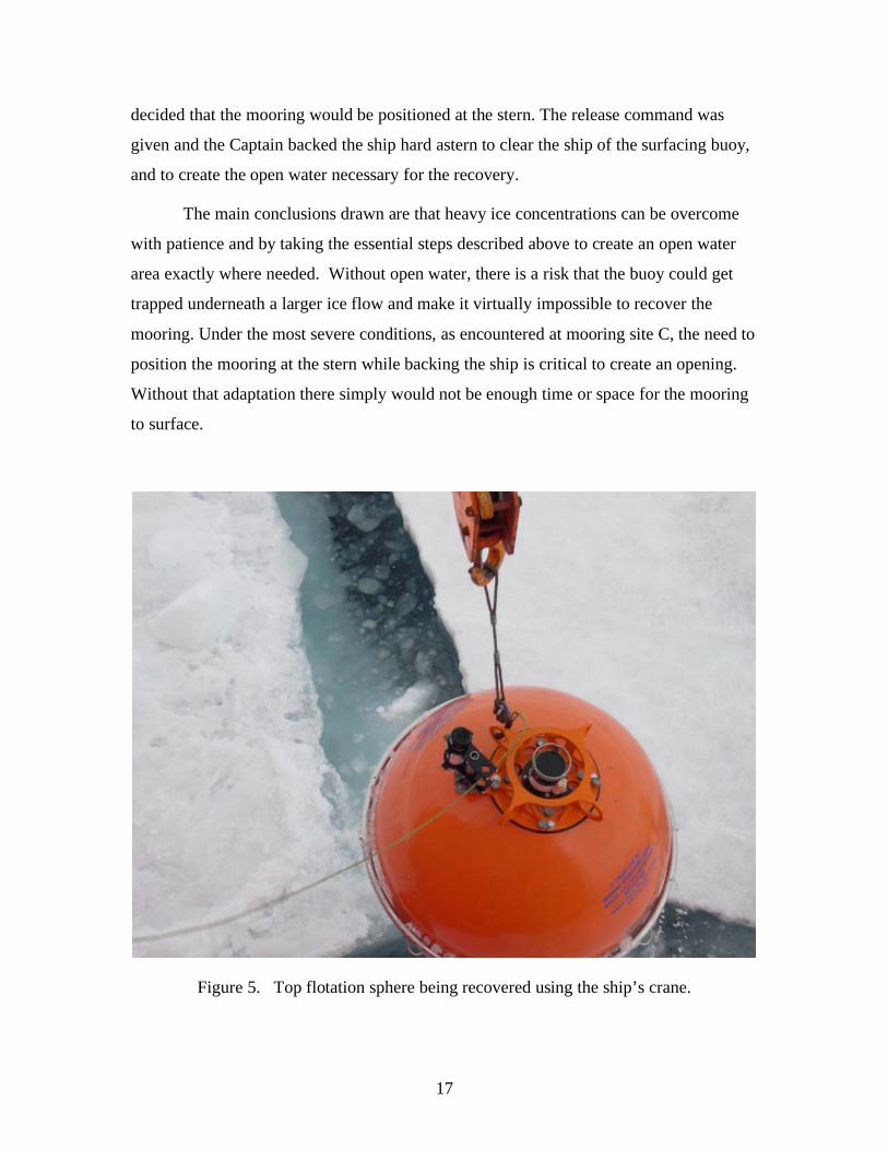
Figure 5. Top flotation sphere being recovered using the ship’s crane.
18
Recovery Operations
Due to the high free board of the LSL fore deck above the water (10 m), it would
be extremely difficult to attach to surfaced mooring components with conventional pick-
up poles and hooks. Some traditional methods used from ships with a high freeboard for
attaching a recovery line were either done using a small boat or by lowering a person in a
man basket. Both methods are time consuming and labor intensive and the launching of
the small boat would be dependent on the ice conditions on the day of recovery. When
working in the ice there is no sea state induced motion, so at the suggestion of the
Boatswain, we adopted a method using an open-end recovery hook and steering tag line.
The recovery hook was suspended on a 3-meter wire pennant from the block on
the crane. Once the mooring sphere had surfaced, the Captain maneuvered the ship to a
point where the sphere was directly under the position of the cranes on the fore deck. The
open ended hook was lowered and skillfully positioned using the steering tag line into the
pickup point on the sphere (Figure 5). Once hooked, the sphere was hoisted up out of the
water. This hooking method relied on skillful coordination between the person steering
the recovery hook and the crane operator but proved to be a reliable and a less time
consuming method of retrieving gear out of the water in ice covered conditions.
Once hoisted out of the water, the crane maneuvered the sphere into a position
directly under the A-frame. A vertical chain stopper with a safety hook attached to the
bitter end (previously suspended from a pad eye on the A-frame) was then snapped into a
sling link (disconnect point) under the sphere. The load was then transferred to the chain
stopper, and the buoy was disconnected and craned to a position on the deck of the ship
where it was secured.
The traction winch tag line was then shackled into the stopped off sling link and
the winch then took the load of the mooring so the vertical chain stopper safety hook
could be removed. At this point, the mooring wire was hauled up far enough for the
removal of the upper MMP bumper stop. Once the bumper was removed, the winch
began hauling in the first shot of 1995 m of 5/16” wire rope. When the termination of the
first shot of wire rope reached the winch, a preassembled ” chain bridle shackled to the
winch base was used to secure it, and the load was transferred to a “Yale Grip” which

19
was shackled to the chain bridle, thus taking all the weight away from the winch drums
(Figure 6).
This allowed the winch tag line to be unshackled and the spool containing the tag
line to be replaced by a collapsible wire coiler. The wire rope would not be reused on
any deployments therefore the coiler allowed ~300 meters of 5/16” to be bundled and
stored then disposed of at WHOI. The coiler was only used on the recovery of A. On
subsequent mooring recoveries, the wire was wound on the empty spools used for the
previous deployment and stored on deck. When the recovery process continued, the
termination was wrapped in canvas to protect the winch drums while spooling around the
drums of the winch.
Figure 6. Wire rope section secured using a Kevlar “Yale” grip. This procedure
was used to remove tension from the traction drums when changing reels on the
traction winch spooler.

20
At the bottom end of the 1995 m shot of wire rope, the MMP was retrieved
resting on a second bumper stop. The MMP was hauled in until the vertical chain stopper
could hook into the sling link just below the bumper stop. The winch then payed out
enough wire rope to transfer the load and position the MMP and bumper stop on the deck
to be disconnected. Once the MMP was safely on deck, the load was shifted back to the
winch and the remaining length of the 1995 m shot of wire was brought in.
However, due to the backup flotation positioned at the bottom of each mooring
and spring effect of the wire upon release, each mooring typically had some
entanglements (wuzzles) in the wire rope which complicated the recovery. Where this
occurred, the mooring had to be stopped off while portions of the wires were sorted and
brought on deck (sometimes manually, at other times in bites using the vertical chain
stopper, and once using the ship’s windlass as a secondary winch). At times,
Figure 7. A particularly nasty entanglement of 9 wire rope segments during the
recovery of the MMP on mooring C. Amazingly, the instrument was undamaged.

21
entanglements of more than 5 different shots of wire were shackled together and wound
around the winch at once, while making sure that they did not tangle while passing
through each block. Once most of the wire shots above the flotation spheres at the
bottom had been recovered, the next task was to recover the spheres.
Figure 8. Cluster of glass floats comprising the backup buoyancy being recovered.
The glass spheres also snarled in large bunches (Figure 8) and sometimes were
wedged just underneath the ice. In order to recover the spheres without putting too much
strain on the wire, it was decided to slowly pay in the winch while the ship slowly
traveled toward the direction of the wire. In other words, the captain went to the spheres
instead of trying to pull the spheres to the ship. This method proved to be extremely
effective and necessary in order to recover this section of the mooring safely. Because of
the enormous snarls, the spheres were literally caught up in the ice and required a vertical
lift instead of a horizontal drag.

22
When the floats were reached, an open-end recovery hook and steering tag line
was used to attach to the cluster. The ship’s crane was lowered, and the Boatswain
hooked onto a link of chain, a shackle, or a pear ring, then raised the cluster to the A-
frame. The vertical chain stopper was used to hook into a termination of wire below the
balls in order to stop off the mooring so the floats could be disconnected and brought
onto the deck.
The final systems to be recovered were the dual releases and BPR (although once
they were recovered before all of the backup buoyancy was retrieved due to the
entanglements). The BPR was mounted on the anchor and chained to one of the releases
at the bottom of the mooring. When the release command was given, the BPR was pulled
from the anchor mount and ascended along with the rest of the mooring. Eventually the
releases and BPR were brought to the surface away from the ice pack and secured to the
vertical chain stopper. The wire was slackened, the termination was disconnected, and
the load was transferred to the ship’s crane. The crane then moved the releases and BPR
to the deck of the ship therefore ending recovery operations.
At critical points during the recovery, especially when instruments were at the
surface, the ship’s bubbler system was used to clear broken ice fragments away from the
starboard side.
Preparations for Redeployment
Once each mooring had been recovered, the next phase of the operation was to
dump data, turn around the recovered mooring flotation packages, check releases, and
prepare the instrumentation for redeployment. A full day between recovery and
redeployment operations was occupied in the mooring refurbishment while the ship
occupied CTD/Rosette stations.
Mooring Systems:
Even though each mooring was in an area without a significant sea state, thus
reducing cyclical wear, the decision was made previously that the wire and hardware
would not be reused primarily due to the tension during deployment and release during

23
recovery. Therefore, complete new sets of wire and hardware were brought for each
mooring.
Each mooring had a total of 52 glass floats (12 sets of 4 and 2 sets of 2) so there
were numerous sets of hardware to change. After recovering the glass flotation balls the
previous day, each set was separated and the used shackles and pear rings were discarded.
Each set required complete new sets of ” trawler chain (4m lengths) and 3/8” hardware
(bolts, fender washers, locks, and nyloc nuts). Two technicians using a “hard hat” table
setup and impact wrenches performed the process in roughly 3-4 hours.
Six releases also needed to be inspected. Ones that passed inspection and
operation test on deck were turned around and redeployed. Each of these required two
new anodes and a new chain bridle with two new links. However, two spare releases
were utilized on the redeployment in lieu of releases with problems (one had a power
problem, and another had a leaky acoustic transducer).
Instrument Systems:
Upon recovery, data was retrieved from the MMPs, ULSs, and BPRs, and the
instruments were cleaned, evaluated and prepared for redeployment. Fortunately, none of
the instruments were damaged, so all could be reused after maintenance. Additionally, in
order to check the drift of the temperature and conductivity sensors on the MMPs, in situ
calibrations were performed using a cast of the IOS SeaBird CTD/Rosette as a reference.
Data was dumped from each MMP and a preliminary analysis was performed to
ensure that the instrument operated properly, and that the acquired data looked
reasonable. The FSI EMCTD on the MMP was removed, configured with an
independent power source, attached to the IOS CTD/Rosette frame, and configured to
acquire data during a cast. This data was compared to the IOS CTD data, and if the
differences were within stated accuracies, the EMCTD was remounted onto the MMP.
Otherwise a spare previously calibrated EMCTD was substituted. The MMP ACMs were
inspected for leakage, and if the data looked reasonable was also reused. The remainder
of the MMP was refurbished for redeployment by installing a new drive roller, spring,
and battery, and was reballasted for weight differences between the old and new battery

24
packs (and old and new sensors, when necessary) and to reduce the difference in current
drawn by the instrument between up and down casts (to enhance battery duration).
All of the ULSs and BPRs recovered in 2004 acquired complete datasets that
looked reasonable. The battery pack for each ULS was replaced and since every anode
was significantly they were replaced. The battery packs and antifouling devices were
replaced in the BPRs.
After rescheduling (see Ostrom et al., 2004 for example), the instruments were
ready for redeployment.
Redeployment Operations
Deployment operations began in the morning. In order to prevent freezing, the
instruments were stored inside until just before arriving on site. While the ship calculated
drift and cleared space in the ice (time varied for each mooring), the ULS and
transponder were mounted to the top float and the BPR was installed on the anchor.
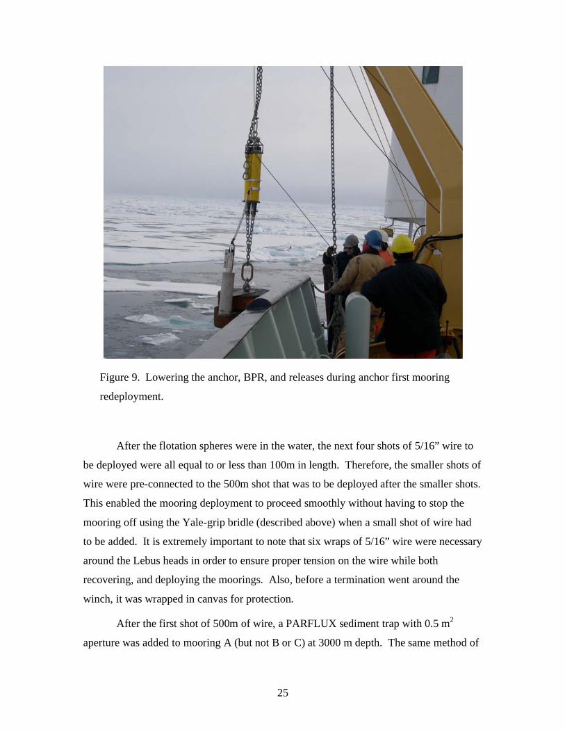
Each mooring was deployed anchor first using the Lebus winch. The first phase
of each mooring deployment required the attachment of the dual Edgetech releases to the
anchor. The ship’s crane was used to both raise the releases into place over the anchor,
and to lower the anchor outside of the A-Frame where the top of the 3m shot of ”
trawler chain was secured to the vertical chain stopper (Figure 9).
The crane then hooked into the first set of glass balls that were staged on the
deck and lowered them until the bottom pear ring could be shackled into the top of the
trawler chain. The load was shifted to the ship’s crane and the vertical chain stopper was
disconnected. The load was lowered until the vertical chain stopper was connected into
the pear ring at the top of the balls. The crane then connected into a second set of glass
balls and the process was mimicked until all 12 sets of balls were connected onto the
mooring array. In order to reduce snarling of the wire rope on future recovery operations,
the glass floats were re-distributed on the redeployed mooring system so that all of the
significant backup buoyancy was directly above the anchor. In other words, 12 sets of 4
were at the bottom, and 2 sets of 2 were at the top.
25
Figure 9. Lowering the anchor, BPR, and releases during anchor first mooring
redeployment.
After the flotation spheres were in the water, the next four shots of 5/16” wire to
be deployed were all equal to or less than 100m in length. Therefore, the smaller shots of
wire were pre-connected to the 500m shot that was to be deployed after the smaller shots.
This enabled the mooring deployment to proceed smoothly without having to stop the
mooring off using the Yale-grip bridle (described above) when a small shot of wire had
to be added. It is extremely important to note that six wraps of 5/16” wire were necessary
around the Lebus heads in order to ensure proper tension on the wire while both
recovering, and deploying the moorings. Also, before a termination went around the
winch, it was wrapped in canvas for protection.
After the first shot of 500m of wire, a PARFLUX sediment trap with 0.5 m2
aperture was added to mooring A (but not B or C) at 3000 m depth. The same method of

26
using the vertical chain stopper and the ship’s crane was used in order to add this
instrument.
After two more 500 m shots and one 10m shot of wire were added to the mooring,
the 1995 m shot was next. WHOI technicians and the ship’s crew were all needed to add
the large shot of wire. Because of hydraulic problems on the spooler, the shot had to be
lifted off the deck manually with assistance from the spooler. Once in place, the wire
was payed out until the bottom termination reached the vertical chain stopper where it
was stopped off and the MMP could be attached. The bottom bumper stop was added,
then the MMP was lifted into place and secured to the wire and carefully lifted outboard
of the A-Frame. Deployment of the wire rope continued. When the termination could be
visibly spotted with only several layers of wire on the reel, the mooring was stopped off
using the Yale grip. The remaining wire on
the reel was taken off and faked onto the
deck. The winch tag line reel was moved
into place on the spooler. Being careful not
to knick or drag the wire, it was coiled onto
the reel. The winch took the load and the
Yale grip was removed. The winch was
payed out until the vertical chain stopper
could take the load. When the mooring was
stopped off, the tag line was removed.
Once all the instruments and wire
were in the water, the last piece of the
mooring to be deployed was the 64”
Syntactic sphere with a ULS and an acoustic
transponder mounted to the top. A release
hook was secured to the top bail of the
sphere using a ‘Lift-All’ sling then attached
to the ship’s crane (Figure 9). Figure 9. Top sphere deployment.
27
The crane then lifted the sphere outboard of the A-Frame and the mooring was
attached to the 1 m shot of ” Trawler Chain. The crane took the load from the vertical
chain stopper so it could be removed. The top sphere was held at the surface of the
water, but before being released, an acoustic range was conducted on one of the releases.
About a minute after releasing the top sphere, the mooring settled at the bottom, and
more ranging was conducted.
The difference between ranges gave the depth of the top sphere below the surface.
The release was disabled, and each redeployment mooring operation was completed in
about 5-6 hours.
Conclusions
Conventional deep ocean, bottom-tethered and instrumented moorings utilizing
wire-rope and glass flotation technology can be routinely deployed and recovered from
icebreakers in the central Arctic ice pack.
In ice-covered regions, deployments must be conducted anchor-first. To account
for the added tension and ensure a responsible safety factor, heavier wire rope and
hardware must be incorporated into the mooring design. Winch and windlass (or
capstan) procedures are both acceptable methods of conducting the deployment.
An accurate acoustic survey to determine the exact location of the mooring,
adequate ice conditions, and skilled ship maneuvering are all essential requirements for a
successful mooring recovery. Windlass (or capstan) procedures could be used for the
recovery, but a traction winch is recommended. Backup buoyancy at the bottom of the
mooring is advised for backup recovery should intermediate lengths of the mooring
system get tangled under ice floes.

28
Acknowledgments
On behalf of all of the scientists from WHOI who participated on the
JWACS/BGEP cruises on the CCGS Louis S. St. Laurent in August 2003 and August
2004, we would like to extend our sincere appreciation to all the Captains, officers, and
crews and to the Canadian Coast Guard organization for the successful fulfillment of the
objectives of our scientific field program in both years. We recognize that the knowledge
and experience of the ship’s leaders was critical to the success of our field program, and
would like to express our gratitude for the hard work, dedication, and professionalism
that was demonstrated by all members during the cruises to the most inaccessible region
of the Arctic Ocean. It has been a privilege and a pleasure working from the Canadian
Coast Guard icebreaker, and we look forward to the opportunity to continue this
cooperation in the future. Specifically for the 2004 expedition, we would like to thank
Captain Andrew McNeill for his excellent leadership and ship handling skills, and
Boatswain Blaine Blinkhorn and his deck crew for their expertise during the mooring
operations.
Furthermore, we would like to thank IOS and JAMSTEC scientists for allowing
us to collaborate and participate on the JWACS cruises, particularly Eddy Carmack
(IOS), Fiona McLaughlin (IOS), Koji Shimada (JAMSTEC), and Motoyo Itoh
(JAMSTEC). Special gratitude goes to Sarah Zimmermann (IOS) for her outstanding
management as chief scientist on the 2004 expedition. Furthermore, we acknowledge the
professional assistance that we obtained from Doug Sieberg (IOS) and Andrew Hamilton
(IOS) during the field operations.
The BGFE project was funded by the NSF Office of Polar Programs ARCSS
Program grant number OPP-0230184, including support for the first year of the field
program (including deployment and recovery of the moorings). Any opinions, findings,
and conclusions or recommendations expressed in this material are those of the authors
and do not necessarily reflect the views of the National Science Foundation. Support to
redeploy and recover the moorings for a second year was provided by the WHOI Ocean
and Climate Change Institute.

29
References
Aagaard, K., C. Darnell, and F. Karig, 1978. Measurements with moored instruments in
ice-covered waters, Deep-Sea Research, Vol. 25, pp. 127-128.
Ostrom, W., Kemp, J., Krishfield, R., and A. Proshutinsky, 2004. Beaufort Gyre
Freshwater Experiment: Deployment Operations and Technology in 2003 WHOI
Technical Report WHOI-2004-1.