the behaviour of a hybrid compressor and ejector … behaviour of a hybrid compressor and ejector...
TRANSCRIPT
ARTICLE IN PRESS
Applied Thermal Engineering xxx (2004) xxx–xxxwww.elsevier.com/locate/apthermeng
The behaviour of a hybrid compressor and ejectorrefrigeration system with refrigerants 134a and 142b
Jorge I. Hern�andez a,*, Rub�en J. Dorantes b, Roberto Best a, Claudio A. Estrada a
a Centro de Investigaci�on en Energ�ıa, UNAM, Apdo. Postal 34, 62580 Temixco, Morelos, Mexicob Departamento de Energ�ıa, UAM Azcapotzalco, Av. San Pablo No. 180, Col. Reynosa Tamaulipas,
02200 Mexico, DF, Mexico
Received 10 October 2003; accepted 21 December 2003
Abstract
A complete theoretical analysis on the thermodynamic behaviour of a HYbrid Compressor and Ejector
Refrigeration System––HYCERS––is carried out. An ejector under optimum performance is employed.
Two working fluids were selected: refrigerant 142b (HCFC142b) which has shown very good characteristics
in air conditioning applications of ejector systems and refrigerant 134a (HFC134a) which is widely used in
refrigeration applications and readily available in most countries. The variation of the generator andcondenser temperatures as well as the intercooler pressure were considered for an evaporator temperature
of )10 �C and a unitary cooling capacity of 1 kW. The ideal efficiency, the enthalpy-based coefficient of
performance, the exergy efficiency and the supplied energy ratio are obtained. With this information, at a
moderate condenser and generator temperature of 30 and 85 �C, respectively, the HYCERS working with
R134a had the best operation with a highest coefficient of performance of 0.48 and an exergy efficiency of
0.25. On the other hand, if a higher condenser temperature is imposed, the HYCERS with R142b had its
best performance at a higher generator temperature. In selecting a working fluid the ejector subsystem
behaviour is determinant in system performance. If a working fluid is badly selected, despite having highentrainment ratios, the system will not function properly. Therefore, the methodology here defined becomes
an effective tool for selecting adequate working fluids and optimum system design conditions. Also, the
employment of a unitary cooling load allows system scaling at any capacity as it increases linearly.
� 2004 Published by Elsevier Ltd.
Keywords: Ejector; Compression; Refrigeration; Cooling; Low temperature energy; Efficient use of energy
* Corresponding author. Tel.: +52-777-3250052; fax: +52-777-3250018.
E-mail address: [email protected] (J.I. Hern�andez).
1359-4311/$ - see front matter � 2004 Published by Elsevier Ltd.
doi:10.1016/j.applthermaleng.2003.12.016
Nomenclature
COP coefficient of performance (dimensionless)e specific exergy (kJ/kg)_E exergy flow rate change (kW)Er supplied energy ratio (dimensionless)h specific enthalpy (kJ/kg)_m mass flow rate (kg/s)n coefficient that defines pINT above pEV
p pressure (MPa)Q heat (kJ)_Q heat flow rate (kW)s specific entropy (kJ/kg K)S entropy (kJ/K)T temperature (�C)U entrainment ratio or vapour mass flow ratio (dimensionless)v specific volume (m3/kg)w specific work (kJ/kg)W ejector mechanical energy, mechanical energy (kJ)_W mechanical power (kW)
D incremente exergy efficiency (dimensionless)g ideal efficiency (dimensionless)
Subscripts and superscripts
b boosterbr reversible boosterCO condenserEJ ejectorEV evaporatorGE generatorINT intercoolerp pumppr reversible pumpr reversibleREF refrigerators hybrid compressor and ejector refrigeration systemTM thermal machine1, 2, . . . , 10 cycle thermodynamic states0,
00primary and secondary fluids
2 J.I. Hern�andez et al. / Applied Thermal Engineering xxx (2004) xxx–xxx
ARTICLE IN PRESS

J.I. Hern�andez et al. / Applied Thermal Engineering xxx (2004) xxx–xxx 3
ARTICLE IN PRESS
1. Introduction
During the last 20 years, the employment of low temperature energy and the conservation ofthe environment have motivated the studies on thermal refrigeration systems. Nowadays, largeamounts of this low temperature energy coming from industrial processes are still wasted, when itsuse could reduce the employment of fossil fuels and its respective generation of greenhouse gases.Furthermore, if ecological or natural working fluids were used in these systems, the emission ofgases that deplete the ozone layer and even cause earth greenhouse effect would also be decreased.Besides, when there is a renewable thermal source, such as solar, the employment of these thermalrefrigeration systems should be considered as an alternative. In Mexico as in many other tropicaldeveloping countries, the application of these systems results ideal because of the high solarradiation levels and the high refrigeration requirements. Also, in these countries ice has beentraditionally used in seafood preservation. Therefore, the development of efficient solar refrig-eration systems for ice production is very important.
Some of the thermal refrigeration systems are three-temperature systems and according to thecorresponding ideal efficiency [1], they reach their best performance at the highest generator andevaporator temperatures, TGE and TEV, and lowest condenser temperature, TCO. The ejectorrefrigeration system behaves in this way and such temperatures result in the highest generatorpressure and the lowest pressure difference between the condenser and evaporator. In practice, if alow evaporator temperature is required, then a high-pressure difference between the condenserand evaporator is set up causing an undesirable ejector operation and system performance inconsequence. To reduce this high-pressure difference, it was proposed to increase the pressure ofthe vapour leaving the evaporator by mechanical compression [1]. Amongst the considered sys-tems, the HYbrid Compressor and Ejector Refrigeration System––HYCERS––presented the bestconfiguration for a proper system operation. It consists of an ejector refrigeration subsystemassisted by a mechanical compression subsystem, as Fig. 1(a) shows. This arrangement allows thisproposed system to be supplied with an adequate combination of thermal and mechanical energyin providing a desired cooling capacity. A theoretical comparative study of the HYCERS was alsocarried out and an attractive system enthalpy-based coefficient of performance, COPs, of 0.767was obtained for a system working with R114 (CFC114) with evaporator, condenser and gen-erator temperatures of )8, 30, 85 �C, respectively and a booster––small compressor––compressionratio of about 2 [1].
HYCERS formal studies have been experimental [2] and theoretical [3–5]. The experimentalstudy considered the operation of an air conditioning system with two optimum performanceejectors of different capacity; one regenerator or preheater; an intercooler––direct contact heatexchanger with R114 as the working fluid in both the ejector and compression subsystems; and abooster compression ratio of about 2 [2]. A simpler refrigeration system using one working fluid,with lower enthalpy-based COPs [1], was preferred over a more complex system that uses a heatexchanger instead of an intercooler, in which a different working fluid is employed in each sub-system. The system design and some operation data were shown. The appropriate controls madethe system to run smoothly and to operate easily.
The first theoretical study considered a solar air conditioning system using one preheater withwater at the ejector and R134a in the compression subsystems, respectively [3]. Only energyrelations were considered and it was found amongst the results that the system mechanical
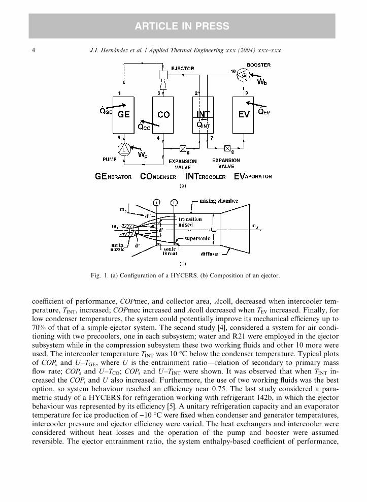
Fig. 1. (a) Configuration of a HYCERS. (b) Composition of an ejector.
4 J.I. Hern�andez et al. / Applied Thermal Engineering xxx (2004) xxx–xxx
ARTICLE IN PRESS
coefficient of performance, COPmec, and collector area, Acoll, decreased when intercooler tem-perature, TINT, increased; COPmec increased and Acoll decreased when TEV increased. Finally, forlow condenser temperatures, the system could potentially improve its mechanical efficiency up to70% of that of a simple ejector system. The second study [4], considered a system for air condi-tioning with two precoolers, one in each subsystem; water and R21 were employed in the ejectorsubsystem while in the compression subsystem these two working fluids and other 10 more wereused. The intercooler temperature TINT was 10 �C below the condenser temperature. Typical plotsof COPs and U–TGE, where U is the entrainment ratio––relation of secondary to primary massflow rate; COPs and U–TCO; COPs and U–TINT were shown. It was observed that when TINT in-creased the COPs and U also increased. Furthermore, the use of two working fluids was the bestoption, so system behaviour reached an efficiency near 0.75. The last study considered a para-metric study of a HYCERS for refrigeration working with refrigerant 142b, in which the ejectorbehaviour was represented by its efficiency [5]. A unitary refrigeration capacity and an evaporatortemperature for ice production of )10 �C were fixed when condenser and generator temperatures,intercooler pressure and ejector efficiency were varied. The heat exchangers and intercooler wereconsidered without heat losses and the operation of the pump and booster were assumedreversible. The ejector entrainment ratio, the system enthalpy-based coefficient of performance,
J.I. Hern�andez et al. / Applied Thermal Engineering xxx (2004) xxx–xxx 5
ARTICLE IN PRESS
the exergy efficiency, es, the intercooler vapour ratio, UINT––relation of the inlet to outlet inter-cooler vapour mass flow rate, the energy ratio, Er––relation of the pump and booster to generatorpower––and its corresponding exergy flow rate change were determined and pointed out asimportant variables. It was found that, for a low intercooler pressure, the system had the highestU , COPs and es for the lowest condenser temperature and the highest generator temperature andejector efficiency. Also, as the intercooler pressure increased, the effect of the compression sub-system caused the COPs to increase significantly.
As above indicated, the ejector manages system operation. This device has no moving parts andcomprises a main convergent–divergent nozzle, a mixing chamber and a diffuser, as Fig. 1(b)shows. Initially, at the ejector entrance and mixing chamber, two fluids with different pressureinteract and mix through an adiabatic thermocompression process. Later, at the diffuser, themixed fluids result at a higher intermediate pressure by a recompression process. In the first case,the primary fluid at high pressure is adiabatically expanded through the convergent–divergentnozzle and discharged at the mixing chamber inlet. There, the secondary fluid at low pressure isentrained as a consequence of the momentum exchange between them. So, the mixing processstarts and the secondary fluid pressure is gradually increased in the mixing chamber until bothfluids reach uniform properties for a complete mixing at the end of this chamber. Then, the re-compression process is carried out at the diffuser. As it is expected, the ejector behaviour iscomplex and many studies were required in the understanding of main operation characteristics,amongst which the ‘‘ejector choking’’ was the most important and results when the entrainmentratio U keeps constant even if the discharged pressure is decreased. This phenomenon was ex-plained by Munday and Bagster [6], who found an analogy with the convergent–divergent nozzlechoking, so when ejector exit pressure is decreased, upstream flows do not change and theentrainment ratio U remains constant. They developed an hypothesis in which this behaviour wasascribed to the secondary fluid once it reaches the sonic condition. They also proposed a methodto determine the section where this choking happens. Earlier, Keenan et al. [7] developed the firstand more complete ejector unidimensional model which explained some of the most commonbehavioural aspects. Evidently, they considered the secondary fluid sonic condition but gave nodetails on how it is performed. Nevertheless, assuming a constant pressure mixing, they found thepossibility of reaching a supersonic flow at the end of the mixing zone. In order to take this flow toa stagnation condition at the end of the diffuser, they considered two options. One through theexistence of a shock wave at the end of the mixing chamber and other by the presence of a naturalthrottling inside the diffuser. Keenan et al. assumed the existence of a shock wave and found acondition where the highest entrainment ratio is reached, which later and with a different focusSokolov and Hershgal called optimum ejector performance [8]. More recently, Lu developed anejector unidimensional model that considers a constant pressure mixing process with a viscousflow [9], unlike Keenan�s model. Furthermore, when the flow became supersonic at the end of themixing chamber a natural throttling at the diffuser was considered. Lu called the transition regimeat the condition in which the maximum entrainment ratio is reached and corresponded to thesecondary fluid choking condition at the entrance of the mixing chamber. In a plot of theentrainment ratio U against the ejector discharge pressure, the ejector behaviour for the Lu�s andSokolov�s models agree completely. Therefore, the transition regime and optimum ejector per-formance are equivalent and corresponded to the highest discharge pressure for the chokingcondition.
6 J.I. Hern�andez et al. / Applied Thermal Engineering xxx (2004) xxx–xxx
ARTICLE IN PRESS
Another important aspect involved in the proper system performance corresponds to theadequate working fluid selection. Amongst others, refrigerant 134a, widely used in refrigeration,as well as R142b had been employed and had shown a good behaviour in air conditioning ejectorsystems [10,11]. Therefore the performance of a HYCERS for refrigeration with these workingfluids has to be further investigated.
As above seen, the HYCERS has a general methodology that considers the efficient use ofenergy with a parameter variation, such as generator, condenser and evaporator temperatures orintercooler pressure [5], whose extent can be widen with the use of Lu�s ejector model in transitionregime and the aforementioned refrigerants 134a and 142b, as well as the obtention and inclusionof the ideal efficiency. Therefore, in the present work a global thermodynamic study of a HY-CERS for a refrigeration application is carried out and the systematic search of optimum systemperformance for a specific working fluid is accomplished.
2. Hybrid compressor and ejector refrigeration system
2.1. System configuration
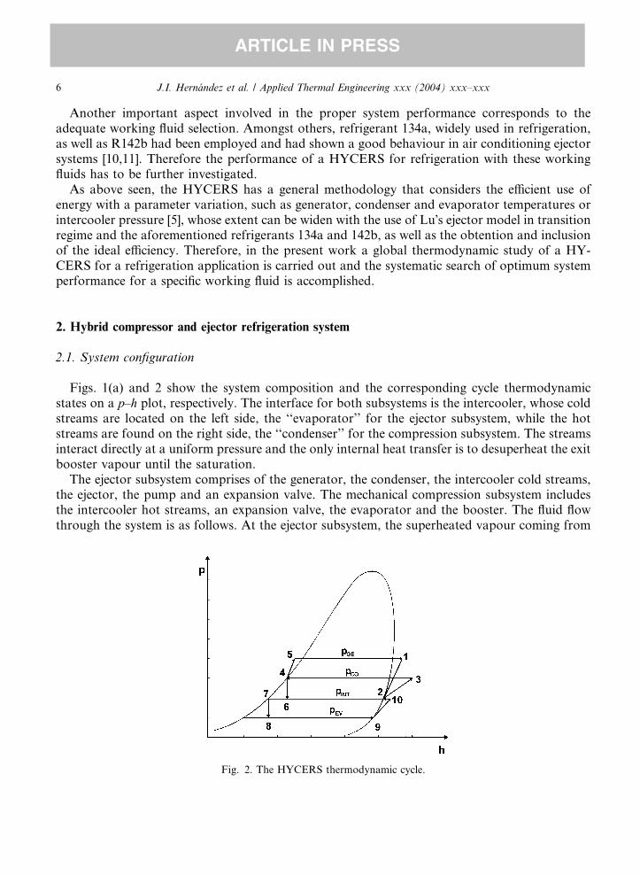
Figs. 1(a) and 2 show the system composition and the corresponding cycle thermodynamicstates on a p–h plot, respectively. The interface for both subsystems is the intercooler, whose coldstreams are located on the left side, the ‘‘evaporator’’ for the ejector subsystem, while the hotstreams are found on the right side, the ‘‘condenser’’ for the compression subsystem. The streamsinteract directly at a uniform pressure and the only internal heat transfer is to desuperheat the exitbooster vapour until the saturation.
The ejector subsystem comprises of the generator, the condenser, the intercooler cold streams,the ejector, the pump and an expansion valve. The mechanical compression subsystem includesthe intercooler hot streams, an expansion valve, the evaporator and the booster. The fluid flowthrough the system is as follows. At the ejector subsystem, the superheated vapour coming from
Fig. 2. The HYCERS thermodynamic cycle.
J.I. Hern�andez et al. / Applied Thermal Engineering xxx (2004) xxx–xxx 7
ARTICLE IN PRESS
the generator, at state 1, and the saturated vapour leaving the intercooler, at state 2, enter theejector and results in a superheated vapour at state 3. This vapour goes to the condenser, where aphase change happens at constant condenser pressure pCO and the saturation state 4 is reached byheat rejection _QCO. This saturated liquid is divided into two streams; one goes into the pump andthe other goes to the expansion valve. The pump receives the liquid and compresses it by means ofthe mechanical power _Wp until the subcooled state 5. The generator evaporates the subcooledliquid at constant generator pressure pGE until it reaches the superheated state 1 by the heat input_QGE. The other part of the condensed liquid fluids through the expansion valve and a liquid–vapour saturated mixture at state 6 is obtained by means of an adiabatic expansion. This satu-rated mixture enters the intercooler, where the saturated liquid turns into saturated vapour instate 2 by means of the incoming heat ‘‘ _QINT’’ at constant intercooler pressure pINT. So, the ejectorsubsystem cycle is closed. At the mechanical compression subsystem, the superheated vapourcoming from the booster enters the intercooler where a phase change occurs and saturation state 7is reached by means of heat extraction ‘‘ _QINT’’ at constant intercooler pressure pINT. The saturatedliquid leaving the intercooler flows through the expansion valve resulting in a liquid–vapoursaturated mixture at state 8. This saturated mixture enters the evaporator, where the saturatedliquid is evaporated at constant evaporator pressure pEV by absorbing an amount of heat _QEV toreach state 9. Then, the booster receives this vapour and compresses it by means of the mechanicalpower _Wb until the superheated state 10 is reached. In this way, the compression subsystem andthe system cycle are closed.
2.2. Ideal system efficiency
Thermodynamically, the ejector can be considered as the coupling of a power subcycle and avapour compression subcycle, both delivering at the same exit pressure [12]. At the power sub-cycle, the primary vapour is expanded to produce the mechanical power _W 0 that is totallytransferred to the compressor and employed as _W 00 in the secondary vapour compression. Finally,after the expansion and compression processes, the primary and secondary fluids are delivered atthe same exit pressure.
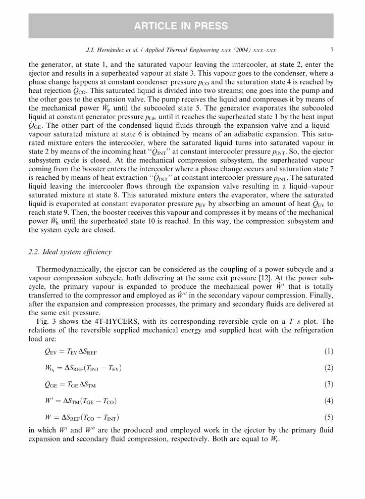
Fig. 3 shows the 4T-HYCERS, with its corresponding reversible cycle on a T–s plot. Therelations of the reversible supplied mechanical energy and supplied heat with the refrigerationload are:
QEV ¼ TEV DSREF ð1Þ
Wbr¼ DSREFðTINT � TEVÞ ð2Þ
QGE ¼ TGE DSTM ð3Þ
W 0 ¼ DSTMðTGE � TCOÞ ð4Þ
W ¼ DSREFðTCO � TINTÞ ð5Þ
in which W 0 and W 00 are the produced and employed work in the ejector by the primary fluidexpansion and secondary fluid compression, respectively. Both are equal to Wr.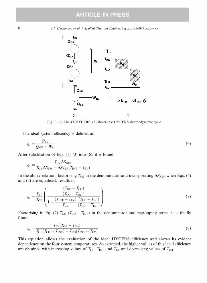
Fig. 3. (a) The 4T-HYCERS. (b) Reversible HYCERS thermodynamic cycle.
8 J.I. Hern�andez et al. / Applied Thermal Engineering xxx (2004) xxx–xxx
ARTICLE IN PRESS
The ideal system efficiency is defined as
gs ¼QEV
QGE þ Wbr
ð6Þ
After substitution of Eqs. (1)–(3) into (6), it is found
gs ¼TEV DSREF
TGE DSTM þ DSREFðTINT � TEVÞ
In the above relation, factorising TGE in the denominator and incorporating DSREF when Eqs. (4)and (5) are equalised, results in
gs ¼TEV
TGE
ðTGE � TCOÞðTCO � TINTÞ
1 þ ðTINT � TEVÞTGE
ðTGE � TCOÞðTCO � TINTÞ
0BB@
1CCA ð7Þ
Factorising in Eq. (7) TGE ðTCO � TINTÞ in the denominator and regrouping terms, it is finallyfound
gs ¼TEVðTGE � TCOÞ
TGEðTCO � TINTÞ � TCOðTINT � TEVÞð8Þ
This equation allows the evaluation of the ideal HYCERS efficiency and shows its evidentdependence on the four system temperatures. As expected, the higher values of this ideal efficiencyare obtained with increasing values of TGE, TINT and TEV and decreasing values of TCO.
J.I. Hern�andez et al. / Applied Thermal Engineering xxx (2004) xxx–xxx 9
ARTICLE IN PRESS
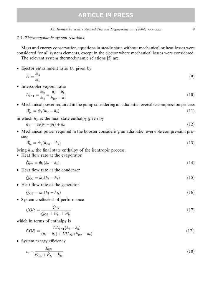
2.3. Thermodynamic system relations
Mass and energy conservation equations in steady state without mechanical or heat losses wereconsidered for all system elements, except in the ejector where mechanical losses were considered.
The relevant system thermodynamic relations [5] are:
• Ejector entrainment ratio U , given by
U ¼ _m2
_m1
ð9Þ
• Intercooler vapour ratio
UINT ¼ _m9
_m2
¼ h2 � h6
h10r � h7
ð10Þ
• Mechanical power required in the pump considering an adiabatic reversible compression process
_Wpr¼ _m1ðh5r � h4Þ ð11Þ
in which h5r is the final state enthalpy given by
h5r ¼ v4ðp5 � p4Þ þ h4 ð12Þ
• Mechanical power required in the booster considering an adiabatic reversible compression pro-cess
_Wbr¼ _m9ðh10r � h9Þ ð13Þ
being h10r the final state enthalpy of the isentropic process.• Heat flow rate at the evaporator
_QEV ¼ _m9ðh9 � h8Þ ð14Þ
• Heat flow rate at the condenser_QCO ¼ _m3ðh3 � h4Þ ð15Þ
• Heat flow rate at the generator_QGE ¼ _m1ðh1 � h5rÞ ð16Þ
• System coefficient of performanceCOPs ¼_QEV
_QGE þ _Wprþ _Wbr
ð17Þ
which in terms of enthalpy is
COPs ¼UUINTðh9 � h8Þ
ðh1 � h4Þ þ UUINTðh10r � h9Þð17
0 Þ
• System exergy efficiency
es ¼_EEV
_EGE þ _Eprþ _Ebr
ð18Þ
10 J.I. Hern�andez et al. / Applied Thermal Engineering xxx (2004) xxx–xxx
ARTICLE IN PRESS
that is the exergy flow rate in the evaporator per each unit of exergy flow rate at the generator,pump and booster. This efficiency considers a common reference for the system cooling capacityand input powers, which expanded form is
es ¼UUINTje8 � e9j
ðe1 � e4Þ þ UUINTðe10r � e9Þð18
0 Þ
• Supplied energy ratio
Er ¼_Wpr
þ _Wbr
_QGE
ð19Þ
is the supplied mechanical power per each unit of heat flow rate supply. Its enthalpy-based form is
Er ¼ ðh5r � h4Þ þ UUINTðh10r � h9Þðh1 � h5rÞ
ð190 Þ
3. Analysis of results
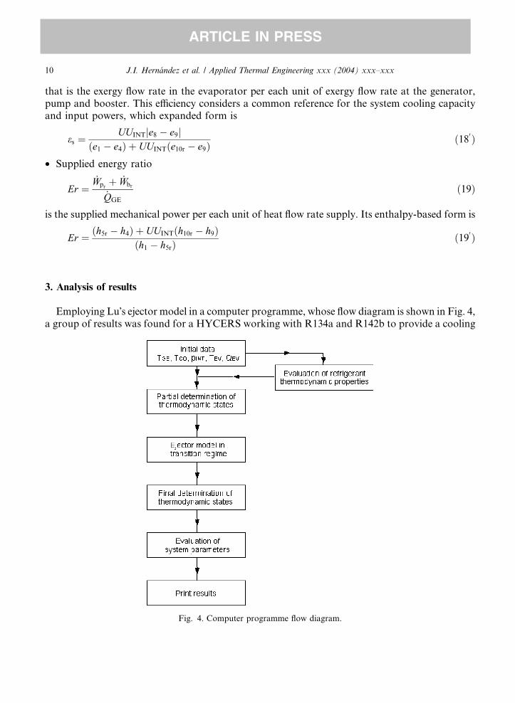
Employing Lu�s ejector model in a computer programme, whose flow diagram is shown in Fig. 4,a group of results was found for a HYCERS working with R134a and R142b to provide a cooling
Fig. 4. Computer programme flow diagram.
J.I. Hern�andez et al. / Applied Thermal Engineering xxx (2004) xxx–xxx 11
ARTICLE IN PRESS
capacity of 1 kW at a temperature of )10 �C, when the generator and condenser temperatures andthe intercooler pressure were varied. Both of these working fluids are ‘‘humid’’ substances, theirisentropic lines have a lower slope than the saturated vapour line, so a slight superheating in thegenerator vapour is required to avoid any condensation in the ejector�s main nozzle expansionprocess. In this way, the element temperatures and the intercooler pressure were varied as follows:
20 �C6 TCO 6 40 �C with DTCO ¼ 10 �C
TCO þ 10 �C6 TGE 6 120 �C with DTGE ¼ 10 �C
For R134a, its TGE upper limit was 90 �C which is near its critical point. TGE defines the saturationworking pressure pGE, as well as, TCO and TEV define the working pressures at the condenser andevaporator, respectively.T1 ¼ T1ðpGE; TGE þ 5 �CÞ
considers a generator superheating of 5 �C.pINT ¼ pEV þ nðpCO � pEVÞ=24 with n ¼ 6 up to 18
in which according to n, pINT is above pEV by the corresponding values from 0.25 to 0.75 ðpCO �pEVÞ with increments of 1/24 this pressure difference. This lowest pINT assures the maximum ejectorwork with Lu�s model.
3.1. Results analysis
In order to validate the HYCERS computer programme that includes Lu�s ejector model, thedesign conditions of the experimental system using R114 and reported by Sokolov and Hershgal[2], were reproduced. Although the data was for an air conditioning application, all the systemvalues were reproduced. The ejector parameters calculated fell between the considered ranges,except for the friction factor which was lower than the expected values. This difference could beoriginated by the very high condenser temperature of around 53 �C used in the experimentalsystem, which is out of the range of Lu�s ejector model. Nevertheless, R114, although not in useanymore, was included in the present refrigeration application for comparison with the workingfluids R134a and R142b.
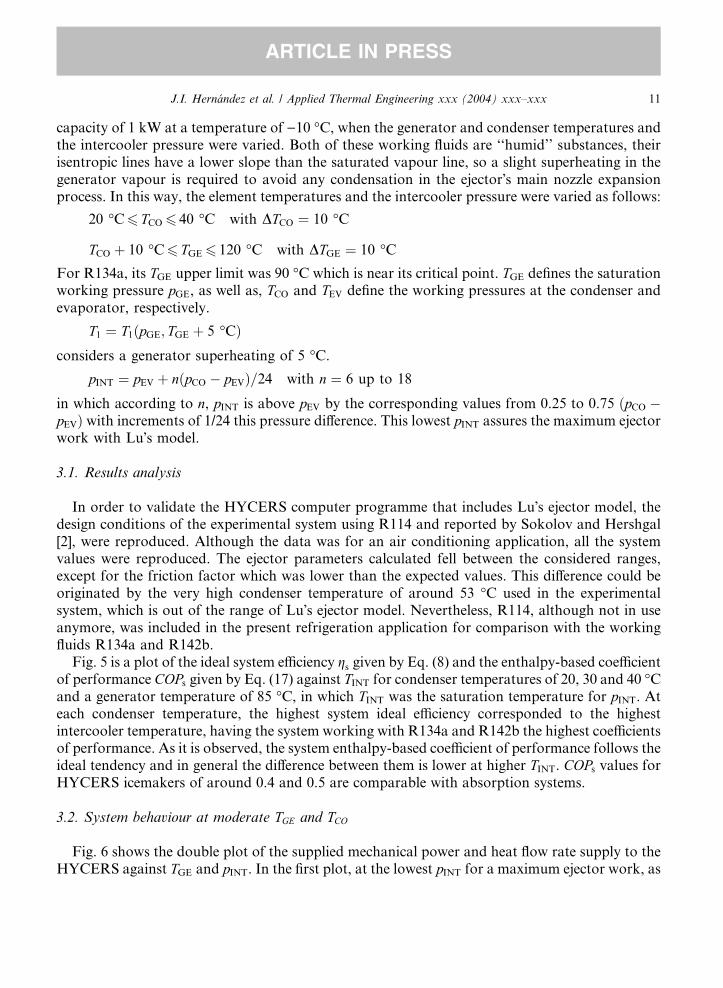
Fig. 5 is a plot of the ideal system efficiency gs given by Eq. (8) and the enthalpy-based coefficientof performance COPs given by Eq. (17) against TINT for condenser temperatures of 20, 30 and 40 �Cand a generator temperature of 85 �C, in which TINT was the saturation temperature for pINT. Ateach condenser temperature, the highest system ideal efficiency corresponded to the highestintercooler temperature, having the system working with R134a and R142b the highest coefficientsof performance. As it is observed, the system enthalpy-based coefficient of performance follows theideal tendency and in general the difference between them is lower at higher TINT. COPs values forHYCERS icemakers of around 0.4 and 0.5 are comparable with absorption systems.
3.2. System behaviour at moderate TGE and TCO
Fig. 6 shows the double plot of the supplied mechanical power and heat flow rate supply to theHYCERS against TGE and pINT. In the first plot, at the lowest pINT for a maximum ejector work, as
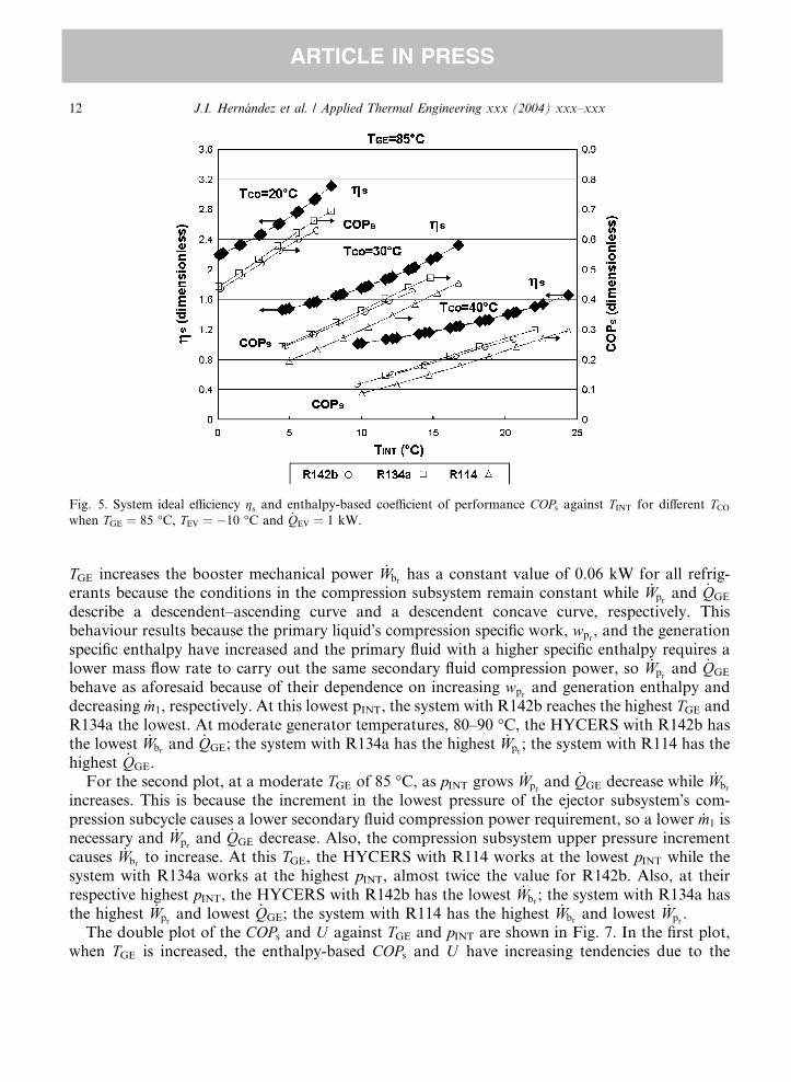
Fig. 5. System ideal efficiency gs and enthalpy-based coefficient of performance COPs against TINT for different TCO
when TGE ¼ 85 �C, TEV ¼ �10 �C and _QEV ¼ 1 kW.
12 J.I. Hern�andez et al. / Applied Thermal Engineering xxx (2004) xxx–xxx
ARTICLE IN PRESS
TGE increases the booster mechanical power _Wbrhas a constant value of 0.06 kW for all refrig-
erants because the conditions in the compression subsystem remain constant while _Wprand _QGE
describe a descendent–ascending curve and a descendent concave curve, respectively. Thisbehaviour results because the primary liquid�s compression specific work, wpr
, and the generationspecific enthalpy have increased and the primary fluid with a higher specific enthalpy requires alower mass flow rate to carry out the same secondary fluid compression power, so _Wpr
and _QGE
behave as aforesaid because of their dependence on increasing wprand generation enthalpy and
decreasing _m1, respectively. At this lowest pINT, the system with R142b reaches the highest TGE andR134a the lowest. At moderate generator temperatures, 80–90 �C, the HYCERS with R142b hasthe lowest _Wbr
and _QGE; the system with R134a has the highest _Wpr; the system with R114 has the
highest _QGE.For the second plot, at a moderate TGE of 85 �C, as pINT grows _Wpr
and _QGE decrease while _Wbr
increases. This is because the increment in the lowest pressure of the ejector subsystem�s com-pression subcycle causes a lower secondary fluid compression power requirement, so a lower _m1 isnecessary and _Wpr
and _QGE decrease. Also, the compression subsystem upper pressure incrementcauses _Wbr
to increase. At this TGE, the HYCERS with R114 works at the lowest pINT while thesystem with R134a works at the highest pINT, almost twice the value for R142b. Also, at theirrespective highest pINT, the HYCERS with R142b has the lowest _Wbr
; the system with R134a hasthe highest _Wpr
and lowest _QGE; the system with R114 has the highest _Wbrand lowest _Wpr
.The double plot of the COPs and U against TGE and pINT are shown in Fig. 7. In the first plot,
when TGE is increased, the enthalpy-based COPs and U have increasing tendencies due to the
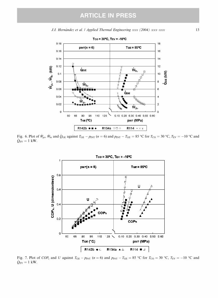
Fig. 7. Plot of COPs and U against TGE � pINT (n ¼ 6) and pINT � TGE ¼ 85 �C for TCO ¼ 30 �C, TEV ¼ �10 �C and_QEV ¼ 1 kW.
Fig. 6. Plot of _Wpr, _Wbr and _QGE against TGE � pINT (n ¼ 6) and pINT � TGE ¼ 85 �C for TCO ¼ 30 �C, TEV ¼ �10 �C and_QEV ¼ 1 kW.
J.I. Hern�andez et al. / Applied Thermal Engineering xxx (2004) xxx–xxx 13
ARTICLE IN PRESS
14 J.I. Hern�andez et al. / Applied Thermal Engineering xxx (2004) xxx–xxx
ARTICLE IN PRESS
respective drastic _QGE and m1 decrease. The COPs with R134a and R142b has similar and highervalues while R114 has the lowest values. Regarding U , the system with the three refrigerants hasvery similar values. For the second plot, when pINT increases, the COPs and U have ascendingcurves. The COPs growth is based on the _QGE and _Wpr
drop, in spite of the _Wbrgrowth. The U
tendency is given again by the drastic decrease in m1. In this case, the system with R134a reachesthe highest COPs of about 0.48 and the system with R114 reaches the highest U value of about0.78.
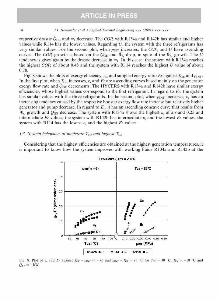
Fig. 8 shows the plots of exergy efficiency, es, and supplied energy ratio Er against TGE and pINT.In the first plot, when TGE increases, es and Er are ascending curves based mainly on the generatorexergy flow rate and _QGE decrements. The HYCERS with R134a and R142b have similar exergyefficiencies, whose highest values correspond to the first refrigerant. In regard to Er, the systemhas similar values with the three refrigerants. In the second plot, when pINT increases, es has anincreasing tendency caused by the respective booster exergy flow rate increase but relatively highergenerator and pump decrease. In regard to Er, it has an ascending concave curve that results from_Wbr
growth and _QGE decrease. The system with R134a shows the highest es of around 0.25 andintermediate Er values; the system with R142b has intermediate es and the lowest Er values; thesystem with R114 has the lowest es and the highest Er values.
3.3. System behaviour at moderate TCO and highest TGE
Considering that the highest efficiencies are obtained at the highest generation temperatures, itis important to know how the system improves with working fluids R134a and R142b at the
Fig. 8. Plot of es and Er against TGE � pINT (n ¼ 6) and pINT � TGE ¼ 85 �C for TCO ¼ 30 �C, TEV ¼ �10 �C and_QEV ¼ 1 kW.
J.I. Hern�andez et al. / Applied Thermal Engineering xxx (2004) xxx–xxx 15
ARTICLE IN PRESS
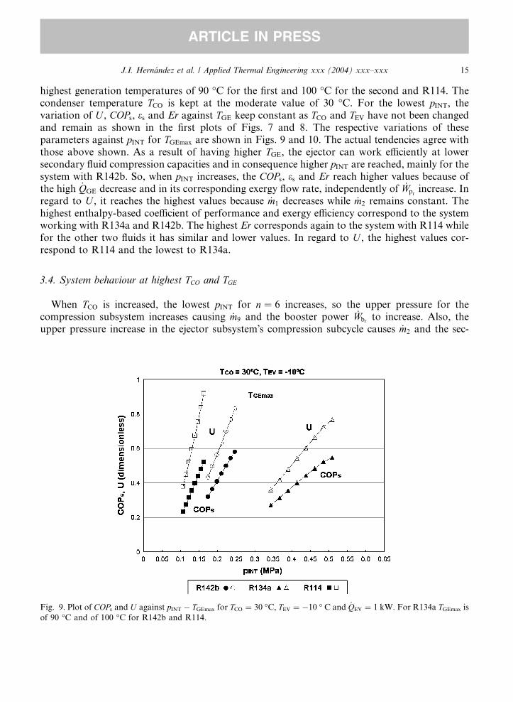
highest generation temperatures of 90 �C for the first and 100 �C for the second and R114. Thecondenser temperature TCO is kept at the moderate value of 30 �C. For the lowest pINT, thevariation of U , COPs, es and Er against TGE keep constant as TCO and TEV have not been changedand remain as shown in the first plots of Figs. 7 and 8. The respective variations of theseparameters against pINT for TGEmax are shown in Figs. 9 and 10. The actual tendencies agree withthose above shown. As a result of having higher TGE, the ejector can work efficiently at lowersecondary fluid compression capacities and in consequence higher pINT are reached, mainly for thesystem with R142b. So, when pINT increases, the COPs, es and Er reach higher values because ofthe high _QGE decrease and in its corresponding exergy flow rate, independently of _Wpr
increase. Inregard to U , it reaches the highest values because _m1 decreases while _m2 remains constant. Thehighest enthalpy-based coefficient of performance and exergy efficiency correspond to the systemworking with R134a and R142b. The highest Er corresponds again to the system with R114 whilefor the other two fluids it has similar and lower values. In regard to U , the highest values cor-respond to R114 and the lowest to R134a.
3.4. System behaviour at highest TCO and TGE
When TCO is increased, the lowest pINT for n ¼ 6 increases, so the upper pressure for thecompression subsystem increases causing _m9 and the booster power _Wbr
to increase. Also, theupper pressure increase in the ejector subsystem�s compression subcycle causes _m2 and the sec-
Fig. 9. Plot of COPs and U against pINT � TGEmax for TCO ¼ 30 �C, TEV ¼ �10 � C and _QEV ¼ 1 kW. For R134a TGEmax is
of 90 �C and of 100 �C for R142b and R114.
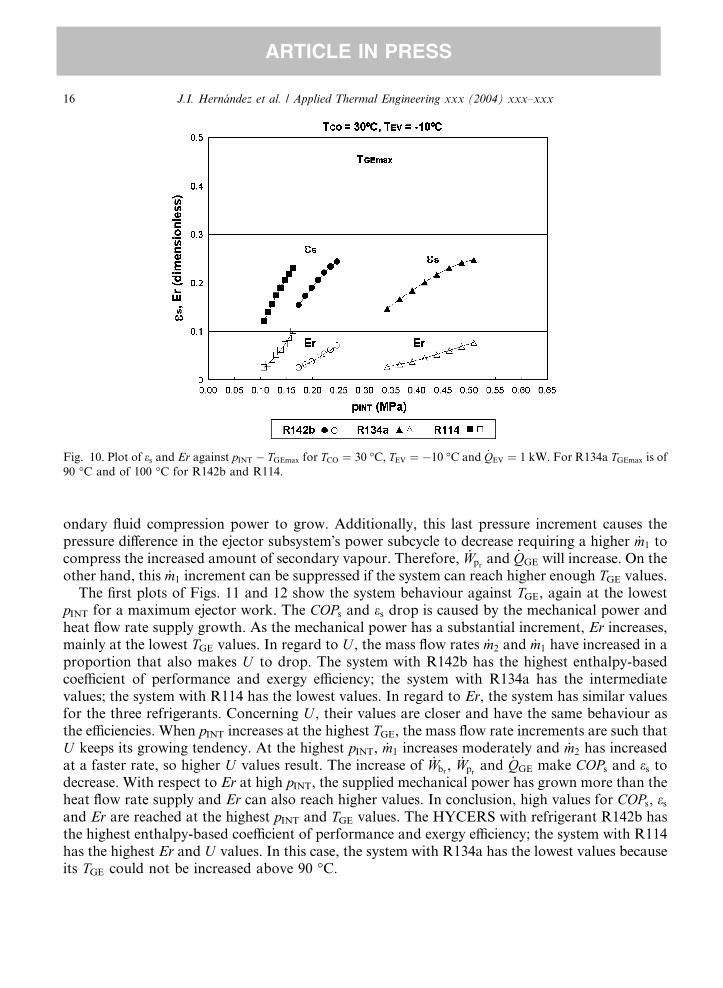
Fig. 10. Plot of es and Er against pINT � TGEmax for TCO ¼ 30 �C, TEV ¼ �10 �C and _QEV ¼ 1 kW. For R134a TGEmax is of
90 �C and of 100 �C for R142b and R114.
16 J.I. Hern�andez et al. / Applied Thermal Engineering xxx (2004) xxx–xxx
ARTICLE IN PRESS
ondary fluid compression power to grow. Additionally, this last pressure increment causes thepressure difference in the ejector subsystem�s power subcycle to decrease requiring a higher _m1 tocompress the increased amount of secondary vapour. Therefore, _Wpr
and _QGE will increase. On theother hand, this _m1 increment can be suppressed if the system can reach higher enough TGE values.
The first plots of Figs. 11 and 12 show the system behaviour against TGE, again at the lowestpINT for a maximum ejector work. The COPs and es drop is caused by the mechanical power andheat flow rate supply growth. As the mechanical power has a substantial increment, Er increases,mainly at the lowest TGE values. In regard to U , the mass flow rates _m2 and _m1 have increased in aproportion that also makes U to drop. The system with R142b has the highest enthalpy-basedcoefficient of performance and exergy efficiency; the system with R134a has the intermediatevalues; the system with R114 has the lowest values. In regard to Er, the system has similar valuesfor the three refrigerants. Concerning U , their values are closer and have the same behaviour asthe efficiencies. When pINT increases at the highest TGE, the mass flow rate increments are such thatU keeps its growing tendency. At the highest pINT, _m1 increases moderately and _m2 has increasedat a faster rate, so higher U values result. The increase of _Wbr
, _Wprand _QGE make COPs and es to
decrease. With respect to Er at high pINT, the supplied mechanical power has grown more than theheat flow rate supply and Er can also reach higher values. In conclusion, high values for COPs, es
and Er are reached at the highest pINT and TGE values. The HYCERS with refrigerant R142b hasthe highest enthalpy-based coefficient of performance and exergy efficiency; the system with R114has the highest Er and U values. In this case, the system with R134a has the lowest values becauseits TGE could not be increased above 90 �C.
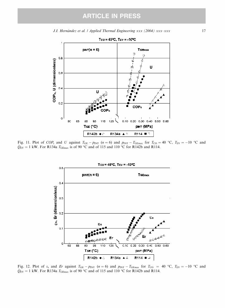
Fig. 11. Plot of COPs and U against TGE � pINT (n ¼ 6) and pINT � TGEmax for TCO ¼ 40 �C, TEV ¼ �10 �C and_QEV ¼ 1 kW. For R134a TGEmax is of 90 �C and of 115 and 110 �C for R142b and R114.
Fig. 12. Plot of es and Er against TGE � pINT (n ¼ 6) and pINT � TGEmax for TCO ¼ 40 �C, TEV ¼ �10 �C and_QEV ¼ 1 kW. For R134a TGEmax is of 90 �C and of 115 and 110 �C for R142b and R114.
J.I. Hern�andez et al. / Applied Thermal Engineering xxx (2004) xxx–xxx 17
ARTICLE IN PRESS
18 J.I. Hern�andez et al. / Applied Thermal Engineering xxx (2004) xxx–xxx
ARTICLE IN PRESS
4. Conclusions
The calculation of the ideal HYCERS efficiency gs sets up the maximum system performanceand its tendency is followed by the system enthalpy-based coefficient of performance COPs for thethree refrigerants.
HYCERS working with R134a had the best performance at a moderate condenser temperatureof 30 �C with a generator temperature of 85 �C and highest COPs of 0.48 and es of 0.25. On theother hand, if higher condenser temperatures are imposed, the HYCERS with R142b has the bestperformance. In regard to the system working with R114, besides it is being phased out, ther-modynamically is not proper for this ice making application independently that it could reachhigher generator temperatures and entrainment ratios. Nevertheless, it is important to point outthat this refrigerant was employed for the very high condenser temperatures managed in aircooled systems or heat pumps.
The exergetic efficiency es reaches a real meaning when the ejector mechanical losses are con-sidered. Even though the system exergy efficiency agreed with the enthalpy-based coefficient ofperformance, the exergy efficiency has a slope fall at the highest pINT that is indicative of a poorgrowth despite of how good the enthalpy-based coefficient of performance growth could be.Therefore, if it is required to work at these pressure levels, a cautious analysis has to be done toavoid an inefficient use of energy.
In the selection of a working fluid, the behaviour of the power subcycle of the ejector subsystemhas to be considered, in addition to the behaviour of the compression subsystem. If it is badlyselected, despite of having high U values, the system will not reach its best performance.Therefore, if higher condenser temperatures are imposed, higher generator temperature are forcedand working fluids with a high critical point are allowed to reach these temperatures and inconsequence achieve higher system efficiencies. Also, from an optimisation point of view, it isconcluded that the best working fluid for a particular application, at fixed TEV and TCO, is the onegiving the highest enthalpy-based coefficient of performance and exergy efficiency at the lowestintercooler pressures and generator temperatures.
From a practical point of view, the HYCERS working with R134a is adequate for moderatecondenser temperatures because also moderate generator temperatures are required. A system likethis has the advantage of being built with of the shelf components, requiring less design andconstruction time at a lower cost. Besides, if solar energy is employed, these generator temper-atures could be easily reached with high quality flat plate collectors.
Therefore, this developed methodology allows knowing the HYCERS thermodynamics and itbecomes into an effective tool for selecting adequate working fluids and optimum system designconditions. Also, the employment of a unitary cooling load allows system scaling at any valuesince system elements capacity grows linearly.
References
[1] M. Sokolov, D. Hershgal, Enhanced ejector refrigeration cycles powered by low grade heat––Part 1: System
characterisation, Int. J. Refrig. 13 (November) (1990) 351–356.
[2] M. Sokolov, D. Hershgal, Enhanced ejector refrigeration cycles powered by low grade heat––Part 3: Experimental
results, Int. J. Refrig. 14 (January) (1991) 24–31, ISSN 0140-7007.
J.I. Hern�andez et al. / Applied Thermal Engineering xxx (2004) xxx–xxx 19
ARTICLE IN PRESS
[3] D.-W. Sun, Solar powered combined ejector-vapour compression cycle for air conditioning and refrigeration,
Energy Convers. Manage. 38 (5) (1997) 479–491, ISSN 019-68904.
[4] D.-W. Sun, Evaluation of a combined ejector-vapour-compression refrigeration system, Int. J. Energy Res. 22
(1998) 333–342.
[5] J.I. Hernandez, C.A. Estrada, R.J. Dorantes, R. Best, Parametric study of a single refrigerant compression
enhanced ejector refrigeration system with R142b, HPC�01, in: Proceedings of the 2nd International Heat Power
Cycles Conference 2001, Paris, France, 5–7 September, 225–232.
[6] J.T. Munday, D.F. Bagster, A new ejector theory applied to steam jet refrigeration, Ind. Eng. Chem. Process Des.
Dev. 16 (4) (1977) 442–449.
[7] J.H. Keenan, E.P. Neumann, F. Lustwerk, An investigation of ejector design by analysis and experiment, ASME J.
Appl. Mech. September (1950) 299–309.
[8] M. Sokolov, D. Hershgal, Enhanced ejector refrigeration cycles powered by low grade heat––Part 1: Design
procedures, Int. J. Refrig. 13 (November) (1990) 357–363.
[9] L.-T. Lu, Etudes th�eorique et exp�erimentale de la production de froid par machine tritherme a ejecteur de fluide
frigorig�e ne, Ph.D. Thesis, Laboratoire d�Energ�etique et d�Automatique, de I�INSA de Lyon, France, 1986.
[10] R. Dorantes, A. Lallemand, Influence de la nature des fluides, purs ou en m�elanges non- az�eotropiques, sur les
performances d�une machine de climatisation �a �ejecto-compresseur, Rev. Int. Froid 18 (1995) 21–30.
[11] D.-W. Sun, Comparative study of the performance of an ejector refrigeration cycle operating with various
refrigerants, Energy Convers. Manage. 40 (1998) 873–884.
[12] G.J. Van Wylen, R.E. Sonntag, Fundamentals of Classic Thermodynamics, John Wiley and Sons, 1985, 247.