the benefits of using a common assembly structure supervisor ... shop layout piping sub-assembly...
TRANSCRIPT
PLM World ‘06
Premium Partners:
The Benefits of Using a Common Assembly Structure
Glen D. LayfieldDresser-RandSupervisor - Design CAD [email protected]
585-596-3729
Brian GoodridgeDresser-RandEngineering Support Tech. [email protected]
585-596-3622
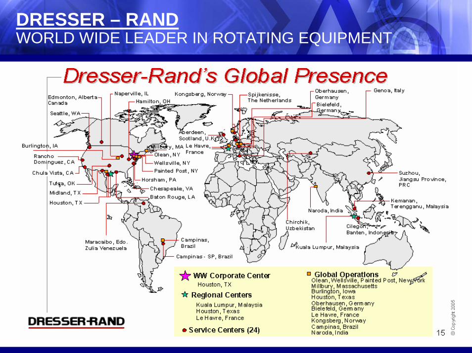
DRESSER – RANDWORLD WIDE LEADER IN ROTATING EQUIPMENT
PERSONAL BIO’S
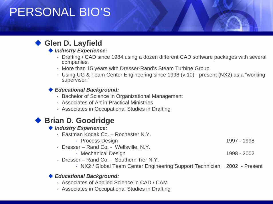
Glen D. LayfieldIndustry Experience:· Drafting / CAD since 1984 using a dozen different CAD software packages with several
companies.· More than 15 years with Dresser-Rand’s Steam Turbine Group.· Using UG & Team Center Engineering since 1998 (v.10) - present (NX2) as a “working
supervisor.”
Educational Background:· Bachelor of Science in Organizational Management· Associates of Art in Practical Ministries· Associates in Occupational Studies in Drafting
Brian D. GoodridgeIndustry Experience:· Eastman Kodak Co. – Rochester N.Y.
· Process Design 1997 - 1998· Dresser – Rand Co. - Wellsville, N.Y.
· Mechanical Design 1998 - 2002· Dresser – Rand Co. - Southern Tier N.Y.
· NX2 / Global Team Center Engineering Support Technician 2002 - Present
Educational Background:· Associates of Applied Science in CAD / CAM· Associates in Occupational Studies in Drafting
History
Dresser-Rand’s CAD JourneyIn the 1970s through mid 1990s Mainframe CADAM was the CAD package used in most of the DR facilities. In mid 1990s DR desired to move away from the Mainframe. Unigraphics was selected as the company wide CAD software for design and development. UG’s migration offering, UGMX was used for making CADM data available in UG. However, because UGMX functioned so much like CADAM, many CAD users continued to use it as a 2D CAD software.
From 2000 through 2002, we attempted in our Wellsville facility, to convert our designs for new units entirely to 3D Unigraphics solid models and assemblies. Because our implementation of UG 3D was “on the fly” with live contracts, we encountered some serious difficulties. Among the most visible to management were 90% increases in hours and similar cycle time increases. Major contributors to these increases were our inability to use legacy CAD data and our struggle with handling large 3D assemblies.
From 2002 through today, we have implemented several process changes to better implement Unigraphics in a manner that makes the best use of legacy 2D design data and 3D capability. In mid 2005, we developed (and in the following months have implemented) the Common Arrangement Assembly Process which we are here to discuss today.

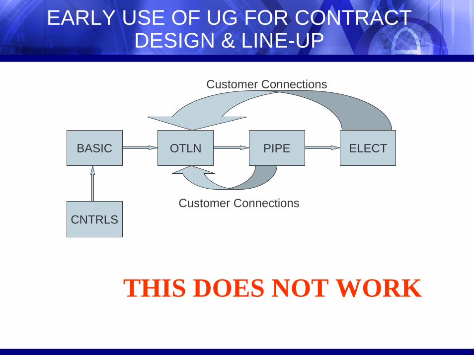
DESIGN & LINE-UP PRIOR TO UNIGRAPHICS
PIPINGALL OUTLINE COMPONENTSLEAKOFFSDRAINSGUAGE VALVESSOLENOIDSSIGHT FLOWSSTEAM/OIL/AIR PIPINGFILTERSACCUMULATORSCONDENSERS
ELECTRICALALL PIPING COMPONENTSGUAGE BOARDSJUNCTION BOXESRTD’SPROBES
CONTROLSTURBINE CASE MACHININGVALVE SEATSCAMSBONNETSBUSHINGSCAM SHAFTBEARING BRACKETSOIL CYLINDERS
BASIC LAYOUTTURBINE CASE MACHINGEE ENDROTORS.E. SUPPORTSBASEPLATESOLEPLATESSE & EE BEARING CASE ASSEMBLYCOUPLING GUARDCOUPLING GUARD ADAPTERSHIMST&T VALVESCONTROLS PARTSSTEAM PATH LAYOUTLABY’SBEARING HOUSINGCENTERLINE SUPPORT HARDWARE1000’S OF INTERNALS
OUTLINEINDICATED BASIC LAYOUT COMPONENTSCONTROLS TOP WORKSCUSTOMER PIPE CONNECTIONSDRIVEN EQUIPMENTGUAGEBOARDSJUNCTION BOXES
CNTRLS
BASIC OTLN PIPE ELECT
EARLY USE OF UG FOR CONTRACT DESIGN & LINE-UP
Customer Connections
Customer Connections
THIS DOES NOT WORK

THE NEW PROCESS
THE COMMON ARRANGEMENTA common arrangement of like components can be used in the Customer Outline, Basic Layout, & other assemblies.
New contract assemblies are cloned structures based on the common arrangement strategy.
Because there is no duplication of parts in assembly structures, load times & model errors are significantly reduced.
Every contract uses the same structure.

THE COMMON PARTS
COMMON ARRANGMENTTURBINE CASE MACHININGEXHAUST ENDROTOR SHAFT ENDSS.E. SUPPORTSBASEPLATESOLEPLATESS.E. & E.E. BEARING CASINGSCOUPLING GUARD & ADAPTERSHIMSBY-PASS PIPESCASE CONNECTIONST&T VALVES & SUPPORTSTURNING GEAR & ADAPTER

ADDING PARTS
MECHANICAL CONTROLS ASSEMBLY
COMMON
CONTROLS SUB ASSEMBLY
DRAWING
CAMSCAM SHAFTBONNETS
BEARING BRACKETSVALVE SEATSBUSHINGS
OIL CYLINDERSACCUATORS
REFERENCE SETS- SOLIDS
– CompleteAssembly
- TOPWORKS – Only Components
That Appear on Top of the Turbine Case
MAKE WORK PART
HOW DO I ADD PARTS?
LOAD

PIPING & ELECTRICAL SHOP LAYOUT
3D PIPING &
ELECTRICALSHOP LAYOUT
PIPING SUB-ASSEMBLY
TOPWORKSREF SET
SOLIDSREF SET
SOLIDSREF SET
TO WORK ON PIPING
LOAD
MAKEWORK PART
TO WORK ON ELECTRICAL
LOAD
MAKEWORK PART
PIPING & ELECTRICALSUB-ASSEMBLY REFERENCE SETS
- SOLIDS- CUSTOMER
CONNECTIONS
ELECTRICALSUB-ASSEMBLY
COMMON
CONTROLSSUB-ASSEMBLY

PIPE & ELECTRICAL SHOP LAYOUT
Light Weight Modules with ReadilyAccessible Global Team Center Data.
Subassemblies are Easily Filtered Allowing Increased Display Flexibility.
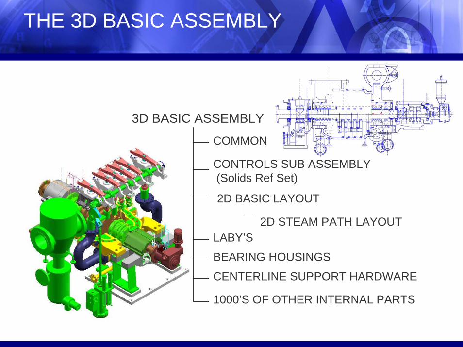
THE 3D BASIC ASSEMBLY
3D BASIC ASSEMBLY
COMMON
CENTERLINE SUPPORT HARDWARE
1000’S OF OTHER INTERNAL PARTS
CONTROLS SUB ASSEMBLY(Solids Ref Set)
LABY’S
2D BASIC LAYOUT
BEARING HOUSINGS
2D STEAM PATH LAYOUT
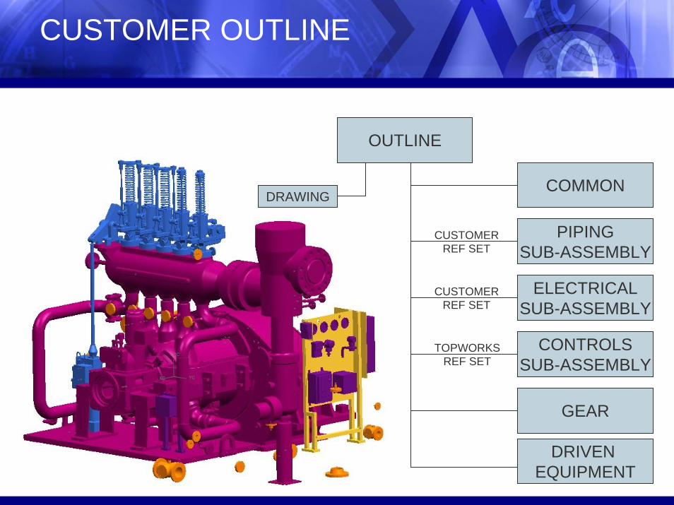
CUSTOMER OUTLINE
OUTLINE
DRAWINGCOMMON
DRIVEN EQUIPMENT
CONTROLSSUB-ASSEMBLY
ELECTRICALSUB-ASSEMBLY
PIPINGSUB-ASSEMBLY
CUSTOMERREF SET
TOPWORKSREF SET
CUSTOMERREF SET
GEAR
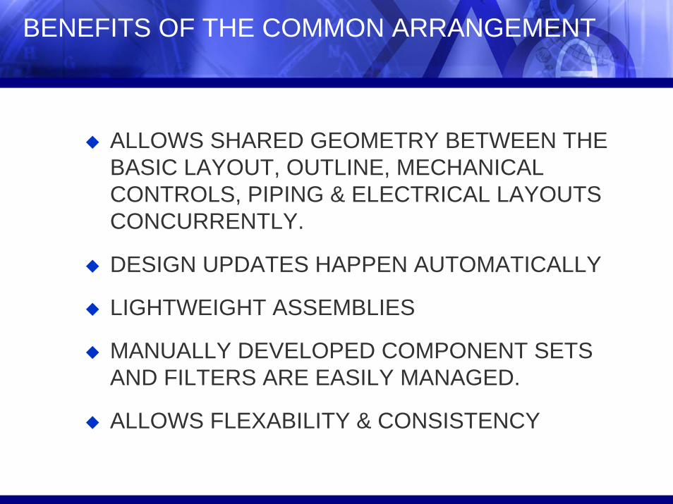
BENEFITS OF THE COMMON ARRANGEMENT
ALLOWS SHARED GEOMETRY BETWEEN THE BASIC LAYOUT, OUTLINE, MECHANICAL CONTROLS, PIPING & ELECTRICAL LAYOUTS CONCURRENTLY.
DESIGN UPDATES HAPPEN AUTOMATICALLY
LIGHTWEIGHT ASSEMBLIES
MANUALLY DEVELOPED COMPONENT SETS AND FILTERS ARE EASILY MANAGED.
ALLOWS FLEXABILITY & CONSISTENCY
PLM World ‘06
Premium Partners:
THE RESULTS FOR C31827 PILOT“We have a friend in Common”
The following graph compares:Adjusted Estimated Hours for C31827Original Estimated Hours for C31827Actual Hours from C31827Actual Hours from Reference Unit U26008.
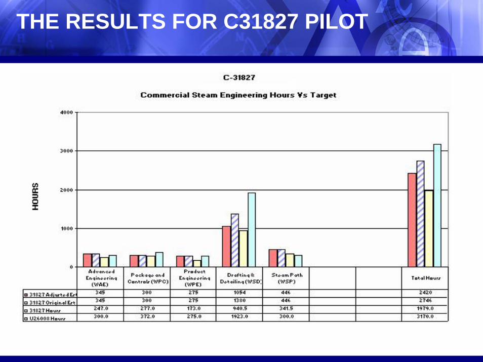
THE RESULTS FOR C31827 PILOT

CONTINUOUS IMPROVEMENTS
Continuous Improvement
Document & Publish The New Process:Reference SetsLayer SettingsModel Checking CriteriaNaming StructuresAssembly Structure and Rules
Continue Base Component Modeling
Collaborative Design between Dresser - Rand Sites with Global Team Center Engineering

QUESTIONS?