the biomechanics of control in upper-extremity … biomechanics of control in upper-extremity...
TRANSCRIPT
The Biomechanics of Control in Upper-Extremity Prostheses
CRAIG L. TAYLOR, Ph.D.1
1 Professor of Engineering, University of California, Los Angeles; member, Advisory Committee on Artificial Limbs, National Research Council, and of the Technical Committee on Prosthetics, ACAL, NRC.
In the rehabilitation of the upper-extremity amputee, structural replacement by prosthetic arm and hand is an obvious requirement, and it poses a comparatively easy task; functional replacement by remote control and by substitute mechanical apparatus is more elusive and hence infinitely harder. For the purposes of functional utility, remaining movements of upper arm, shoulder, and torso must be harnessed, and use must be made of a variety of mechanical devices which amplify remaining resources by alternators, springs, locks, and switching arrangements. The facility of control attained through this apparatus is the key to its ultimate value.
The future of upper-extremity prosthetics depends upon an ever-increasing understanding of the mechanics of the human body by all who minister to the amputee—prosthetist, surgeon, and therapist alike. It must always be stressed that the final goal is an amputee who can function. Too often there is a tendency to put undue faith in the marvels of mechanism alone, when in fact it is the man-machine combination that determines performance. It is in this broad frame of reference that the biomechanical basis of upper-extremity control must be approached.
PROSTHETICS ANTHROPOMETRY
SURFACE LANDMARKS
If successful control is to be obtained, the various components of the prosthesis must be positioned with a good degree of accuracy.
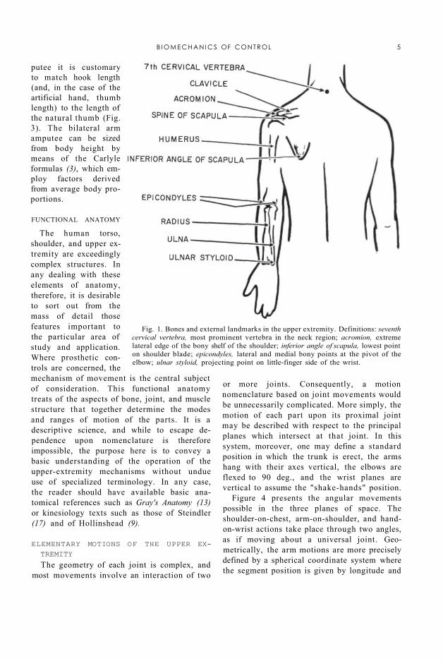
To do so requires reference points on the body, of which the most satisfactory are certain bony landmarks. Most of these skeletal prominences protrude to such an extent that location is easily possible by eye. Others require palpation, and this method should be used to verify observation in every case. The bones most concerned in upper-extremity anthropometry are the clavicle, the scapula, the humerus, the ulna, and the seventh cervical vertebra. Surface indications of protuberances, angles, or other features of these bones constitute the landmarks, the locations and definitions being given in Figure 1.
ARM AND TRUNK MEASUREMENTS
2 In everyday language the word "arm" is of course taken to mean the entire upper extremity, or at least that portion between shoulder and wrist. In anatomical terms, "arm" is reserved specifically for the segment between shoulder and elbow, that between elbow and wrist being the "forearm." Although in the lower extremity the word "leg" commonly means the entire lower limb, whereas anatomically the "leg" is that segment between knee and ankle, confusion is easily avoided because we have the special word "shank." No such spare word is available to describe the humeral segment of the upper limb.—ED.
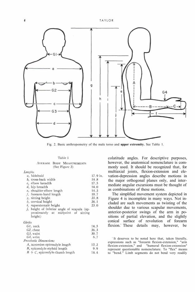
The typical male torso and upper extremity are shown in Figure 2, which, together with Table 1, was derived from average measurements on Army personnel (16). Such an average form serves to establish harness patterns and control paths. The arm, forearm, and epicondyle-thumb lengths 2 constitute the basis of sizing prostheses (2). Arm length places the artificial elbow; forearm length locates the terminal device. The epicondyle-thumb length is an important over-all sizing reference because in the unilateral arm am-
4
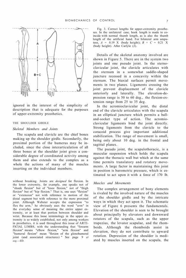
putee it is customary to match hook length (and, in the case of the artificial hand, thumb length) to the length of the natural thumb (Fig. 3). The bilateral arm amputee can be sized from body height by means of the Carlyle formulas (3), which employ factors derived from average body proportions.
Fig. 1. Bones and external landmarks in the upper extremity. Definitions: seventh cervical vertebra, most prominent vertebra in the neck region; acromion, extreme lateral edge of the bony shelf of the shoulder; inferior angle of scapula, lowest point on shoulder blade; epicondyles, lateral and medial bony points at the pivot of the elbow; ulnar styloid, projecting point on little-finger side of the wrist.
FUNCTIONAL ANATOMY
The human torso, shoulder, and upper extremity are exceedingly complex structures. In any dealing with these elements of anatomy, therefore, it is desirable to sort out from the mass of detail those features important to the particular area of study and application. Where prosthetic controls are concerned, the mechanism of movement is the central subject of consideration. This functional anatomy treats of the aspects of bone, joint, and muscle structure that together determine the modes and ranges of motion of the parts. It is a descriptive science, and while to escape dependence upon nomenclature is therefore impossible, the purpose here is to convey a basic understanding of the operation of the upper-extremity mechanisms without undue use of specialized terminology. In any case, the reader should have available basic anatomical references such as Gray's Anatomy (13) or kinesiology texts such as those of Steindler (17) and of Hollinshead (9).
ELEMENTARY MOTIONS OF THE UPPER EXTREMITY The geometry of each joint is complex, and
most movements involve an interaction of two
or more joints. Consequently, a motion nomenclature based on joint movements would be unnecessarily complicated. More simply, the motion of each part upon its proximal joint may be described with respect to the principal planes which intersect at that joint. In this system, moreover, one may define a standard position in which the trunk is erect, the arms hang with their axes vertical, the elbows are flexed to 90 deg., and the wrist planes are vertical to assume the "shake-hands" position.
Figure 4 presents the angular movements possible in the three planes of space. The shoulder-on-chest, arm-on-shoulder, and hand-on-wrist actions take place through two angles, as if moving about a universal joint. Geometrically, the arm motions are more precisely defined by a spherical coordinate system where the segment position is given by longitude and
B I O M E C H A N I C S OF CONTROL 5
colatitude angles. For descriptive purposes, however, the anatomical nomenclature is commonly used. It should be recognized that, for multiaxial joints, flexion-extension and elevation-depression angles describe motions in the major orthogonal planes only, and intermediate angular excursions must be thought of as combinations of these motions.
Fig. 2. Basic anthropometry of the male torso and upper extremity. See Table 1.
The simplified movement system depicted in Figure 4 is incomplete in many ways. Not included are such movements as twisting of the shoulder due to various scapular movements, anterior-posterior swings of the arm in positions of partial elevation, and the slightly conical surface of revolution of forearm flexion.3 These details may, however, be
3 It deserves to be noted here that, taken literally, expressions such as "forearm flexion-extension," "arm flexion-extension," and "humeral flexion-extension" represent questionable nomenclature. To "flex" means to "bend." Limb segments do not bend very readily
6 T A Y L O R
without breaking. Joints are designed for flexion. In the lower extremity, for example, one speaks not of "shank flexion" but of "knee flexion," not of "thigh flexion" but of "hip flexion." That is, one uses "flexion" or "extension" not with reference to motion of the distal segment but with reference to the more proximal joint. Although Webster accepts the expression "to flex the arm," he obviously uses the word "arm" in the everyday sense of meaning the entire upper extremity, or at least that portion between shoulder and wrist. Because this loose terminology in the upper extremity is so widely established, not only among workers in prosthetics, it is used throughout this issue of ARTIFICIAL LIMBS, with the understanding that "forearm flexion" means "elbow flexion," "arm flexion" and "humeral flexion" mean "flexion of the glenohumeral joint (and associated structures) " See page 9 et seq.—ED.
ignored in the interest of the simplicity of description that is adequate for the purposes of upper-extremity prosthetics.
Fig. 3. Correct lengths for upper-extremity prostheses. In the unilateral case, hook length is made to coincide with normal thumb length, as is also the thumb length of the artificial hand. For bilateral arm amputees, A = 0.19 X (body height); B + C = 0.21 X (body height). After Carlyle (J).
THE SHOULDER GIRDLE
Skeletal Members and Joints The scapula and clavicle are the chief bones
making up the shoulder girdle. Secondarily, the proximal portion of the humerus may be included, since the close interarticulation of all three bones at the shoulder joint gives a considerable degree of coordinated activity among them and also extends to the complex as a whole the actions of many of the muscles inserting on the individual members.
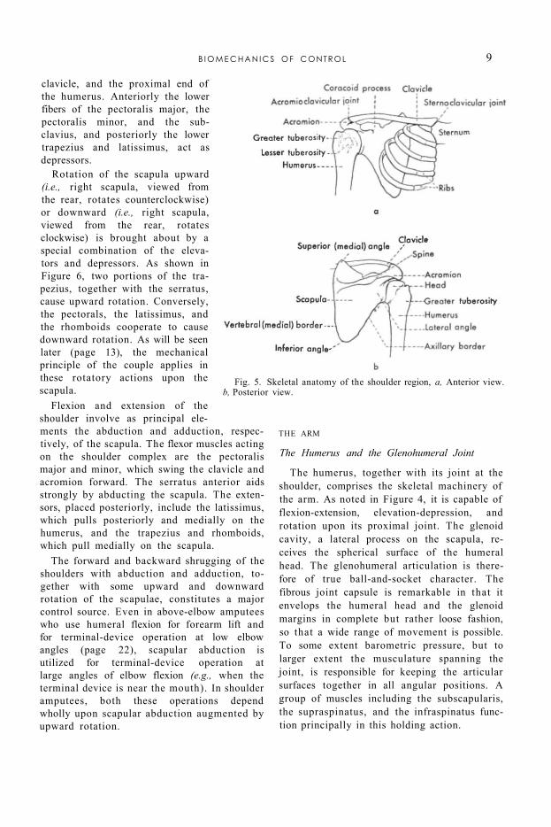
Details of the skeletal anatomy involved are shown in Figure 5. There are in the system two joints and one pseudo joint. In the sternoclavicular joint, the clavicle articulates with the sternum in a somewhat saddle-shaped juncture recessed in a concavity within the sternum. The biaxial surfaces permit movements in two planes. Ligaments crossing the joint prevent displacement of the clavicle anteriorly and laterally. The elevation-depression range is 50 to 60 deg., the flexion-extension range from 25 to 35 deg.
In the acromioclavicular joint, the distal end of the clavicle articulates with the scapula in an elliptical juncture which permits a ball-and-socket type of action. The acromioclavicular ligaments bind the joint directly. Strong ligaments from the clavicle to the coracoid process give important additional stabilization. The range of movement is small, being only about 10 deg. in the frontal and sagittal planes.
The pseudo joint, the scapulothoracic, is a muscular suspension which holds the scapula against the thoracic wall but which at the same time permits translatory and rotatory movements. A large factor in maintaining this joint in position is barometric pressure, which is estimated to act upon it with a force of 170 lb.
Muscles and Movements The complex arrangement of bony elements
is rivaled by the involved nature of the muscles of the shoulder girdle and by the intricate ways in which they act upon it. The schematic view of Figure 6 presents the fundamentals. Elevation of the shoulder is seen to be brought about principally by elevators and downward rotators of the scapula, such as the upper trapezius, the levator scapulae, and the rhomboids. Although the rhomboids assist in elevation, they do not contribute to upward rotation. Depression of the shoulder is mediated by muscles inserted on the scapula, the
B I O M E C H A N I C S OF CONTROL 7
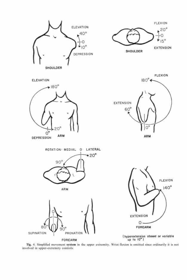
Tig. 4. Simplified movement system in the upper extremity. Wrist flexion is omitted since ordinarily it is not involved in upper-extremity controls.
clavicle, and the proximal end of the humerus. Anteriorly the lower fibers of the pectoralis major, the pectoralis minor, and the sub-clavius, and posteriorly the lower trapezius and latissimus, act as depressors.
Rotation of the scapula upward (i.e., right scapula, viewed from the rear, rotates counterclockwise) or downward (i.e., right scapula, viewed from the rear, rotates clockwise) is brought about by a special combination of the elevators and depressors. As shown in Figure 6, two portions of the trapezius, together with the serratus, cause upward rotation. Conversely, the pectorals, the latissimus, and the rhomboids cooperate to cause downward rotation. As will be seen later (page 13), the mechanical principle of the couple applies in these rotatory actions upon the scapula.
Flexion and extension of the shoulder involve as principal elements the abduction and adduction, respectively, of the scapula. The flexor muscles acting on the shoulder complex are the pectoralis major and minor, which swing the clavicle and acromion forward. The serratus anterior aids strongly by abducting the scapula. The extensors, placed posteriorly, include the latissimus, which pulls posteriorly and medially on the humerus, and the trapezius and rhomboids, which pull medially on the scapula.
The forward and backward shrugging of the shoulders with abduction and adduction, together with some upward and downward rotation of the scapulae, constitutes a major control source. Even in above-elbow amputees who use humeral flexion for forearm lift and for terminal-device operation at low elbow angles (page 22), scapular abduction is utilized for terminal-device operation at large angles of elbow flexion (e.g., when the terminal device is near the mouth). In shoulder amputees, both these operations depend wholly upon scapular abduction augmented by upward rotation.
Fig. 5. Skeletal anatomy of the shoulder region, a, Anterior view. b, Posterior view.
THE ARM
The Humerus and the Glenohumeral Joint
The humerus, together with its joint at the shoulder, comprises the skeletal machinery of the arm. As noted in Figure 4, it is capable of flexion-extension, elevation-depression, and rotation upon its proximal joint. The glenoid cavity, a lateral process on the scapula, receives the spherical surface of the humeral head. The glenohumeral articulation is therefore of true ball-and-socket character. The fibrous joint capsule is remarkable in that it envelops the humeral head and the glenoid margins in complete but rather loose fashion, so that a wide range of movement is possible. To some extent barometric pressure, but to larger extent the musculature spanning the joint, is responsible for keeping the articular surfaces together in all angular positions. A group of muscles including the subscapularis, the supraspinatus, and the infraspinatus function principally in this holding action.
B I O M E C H A N I C S OF CONTROL 9
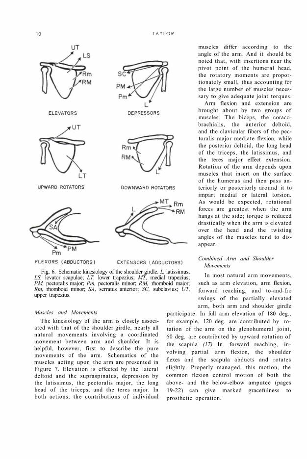
Fig. 6. Schematic kinesiology of the shoulder girdle. L, latissimus; LS, levator scapulae; LT, lower trapezius; MT, medial trapezius; PM, pectoralis major; Pm, pectoralis minor; RM, rhomboid major; Rm, rhomboid minor; SA, serratus anterior; SC, subclavius; UT, upper trapezius.
Muscles and Movements The kinesiology of the arm is closely associ
ated with that of the shoulder girdle, nearly all natural movements involving a coordinated movement between arm and shoulder. It is helpful, however, first to describe the pure movements of the arm. Schematics of the muscles acting upon the arm are presented in Figure 7. Elevation is effected by the lateral deltoid and the supraspinatus, depression by the latissimus, the pectoralis major, the long head of the triceps, and the teres major. In both actions, the contributions of individual
muscles differ according to the angle of the arm. And it should be noted that, with insertions near the pivot point of the humeral head, the rotatory moments are proportionately small, thus accounting for the large number of muscles necessary to give adequate joint torques.
Arm flexion and extension are brought about by two groups of muscles. The biceps, the coraco-brachialis, the anterior deltoid, and the clavicular fibers of the pectoralis major mediate flexion, while the posterior deltoid, the long head of the triceps, the latissimus, and the teres major effect extension. Rotation of the arm depends upon muscles that insert on the surface of the humerus and then pass anteriorly or posteriorly around it to impart medial or lateral torsion. As would be expected, rotational forces are greatest when the arm hangs at the side; torque is reduced drastically when the arm is elevated over the head and the twisting angles of the muscles tend to disappear.
Combined Arm and Shoulder Movements In most natural arm movements,
such as arm elevation, arm flexion, forward reaching, and to-and-fro swings of the partially elevated arm, both arm and shoulder girdle
participate. In full arm elevation of 180 deg., for example, 120 deg. are contributed by rotation of the arm on the glenohumeral joint, 60 deg. are contributed by upward rotation of the scapula (17). In forward reaching, involving partial arm flexion, the shoulder flexes and the scapula abducts and rotates slightly. Properly managed, this motion, the common flexion control motion of both the above- and the below-elbow amputee (pages 19-22) can give marked gracefulness to prosthetic operation.
10 T A Y L O R
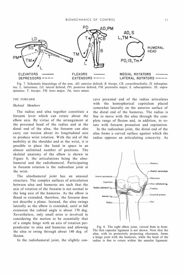
Fig. 7. Schematic kinesiology of the arm. AD, anterior deltoid; B, biceps; CB, coracobrachialis; IS, infraspinatus; L, latissimus; LD, lateral deltoid; PD, posterior deltoid; PM, pectoralis major; S, subscapularis; SS, supra-spinatus; T, triceps; TM, teres major; Tm, teres minor.
Fig. 8. The right elbow joint, viewed from in front. The thin capsular ligament is not shown. Note that the ulna, with its posteriorly projecting olecranon, forms a hinge joint with the humerus, while the head of the radius is free to rotate within the annular ligament.
THE FOREARM
Skeletal Members
The radius and ulna together constitute a forearm lever which can rotate about the elbow axis. By virtue of the arrangement at the proximal head of the radius and at the distal end of the ulna, the forearm can also carry out torsion about its longitudinal axis to produce wrist rotation. With the aid of the mobility at the shoulder and at the wrist, it is possible to place the hand in space in an almost unlimited number of positions. The skeletal anatomy of the elbow is shown in Figure 8, the articulations being the ulno-humeral and the radiohumeral. Participating in forearm rotation is the radioulnar joint at the wrist.
The ulnohumeral joint has an unusual structure. The complex surfaces of articulation between ulna and humerus are such that the axis of rotation of the forearm is not normal to the long axis of the humerus. As the elbow is flexed or extended, therefore, the forearm does not describe a plane. Instead, the ulna swings laterally as the elbow is extended, until at full extension the cubital angle is about 170 deg. Xevertheless, only small error is involved in considering the motion to be essentially that of a simple hinge with an axis of rotation perpendicular to ulna and humerus and allowing the ulna to swing through about 140 deg. of flexion.
In the radiohumeral joint, the slightly con
cave proximal end of the radius articulates with the hemispherical capitulum placed somewhat laterally on the anterior surface of the distal end of the humerus. The radius is free to move with the ulna through the complete range of flexion and, in addition, to rotate with forearm pronation and supination.
In the radioulnar joint, the distal end of the ulna forms a curved surface against which the radius opposes an articulating concavity. As
B I O M E C H A N I C S OF CONTROL 11
the forearm goes through a pronation-supination range of about 170 deg., the radius "swings like a gate" about the distal end of the ulna.
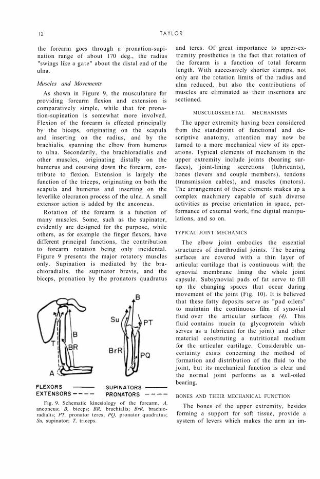
Muscles and Movements As shown in Figure 9, the musculature for
providing forearm flexion and extension is comparatively simple, while that for pronation-supination is somewhat more involved. Flexion of the forearm is effected principally by the biceps, originating on the scapula and inserting on the radius, and by the brachialis, spanning the elbow from humerus to ulna. Secondarily, the brachioradialis and other muscles, originating distally on the humerus and coursing down the forearm, contribute to flexion. Extension is largely the function of the triceps, originating on both the scapula and humerus and inserting on the leverlike olecranon process of the ulna. A small extensor action is added by the anconeus.
Rotation of the forearm is a function of many muscles. Some, such as the supinator, evidently are designed for the purpose, while others, as for example the finger flexors, have different principal functions, the contribution to forearm rotation being only incidental. Figure 9 presents the major rotatory muscles only. Supination is mediated by the brachioradialis, the supinator brevis, and the biceps, pronation by the pronators quadratus
and teres. Of great importance to upper-extremity prosthetics is the fact that rotation of the forearm is a function of total forearm length. With successively shorter stumps, not only are the rotation limits of the radius and ulna reduced, but also the contributions of muscles are eliminated as their insertions are sectioned.
Fig. 9. Schematic kinesiology of the forearm. A, anconeus; B, biceps; BR, brachialis; BrR, brachioradialis; PT, pronator teres; PQ, pronator quadratus; Su, supinator; T, triceps.
MUSCULOSKELETAL MECHANISMS
The upper extremity having been considered from the standpoint of functional and descriptive anatomy, attention may now be turned to a more mechanical view of its operations. Typical elements of mechanism in the upper extremity include joints (bearing surfaces), joint-lining secretions (lubricants), bones (levers and couple members), tendons (transmission cables), and muscles (motors). The arrangement of these elements makes up a complex machinery capable of such diverse activities as precise orientation in space, performance of external work, fine digital manipulations, and so on.
TYPICAL JOINT MECHANICS
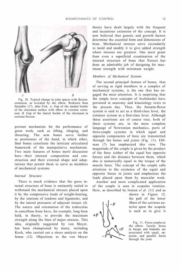
The elbow joint embodies the essential structures of diarthrodial joints. The bearing surfaces are covered with a thin layer of articular cartilage that is continuous with the synovial membrane lining the whole joint capsule. Subsynovial pads of fat serve to fill up the changing spaces that occur during movement of the joint (Fig. 10). It is believed that these fatty deposits serve as "pad oilers" to maintain the continuous film of synovial fluid over the articular surfaces (4). This fluid contains mucin (a glycoprotein which serves as a lubricant for the joint) and other material constituting a nutritional medium for the articular cartilage. Considerable uncertainty exists concerning the method of formation and distribution of the fluid to the joint, but its mechanical function is clear and the normal joint performs as a well-oiled bearing.
BONES AND THEIR MECHANICAL FUNCTION
The bones of the upper extremity, besides forming a support for soft tissue, provide a system of levers which makes the arm an im-
12 T A Y L O R
portant mechanism for the performance of gross work, such as lifting, slinging, and thrusting. The arm bones serve further as positioners of the hand, in which other, finer bones constitute the intricate articulated framework of the manipulative mechanism. Two main features of bones merit discussion here—their internal composition and construction and their external shape and adaptations that permit them to serve as members of mechanical systems.
Internal Structure There is much evidence that the gross in
ternal structure of bone is eminently suited to withstand the mechanical stresses placed upon it by the compressive loads of weight-bearing, by the tensions of tendons and ligaments, and by the lateral pressures of adjacent tissues (4). The nature and orientation of the trabeculae in cancellous bone have, for example, long been held, in theory, to provide the maximum strength along the lines of major stresses. This idea, originally suggested by von Meyer, has been championed by many, including Koch, who carried out a stress analysis on the femur (12). Objections to the von Meyer
theory have dealt largely with the frequent and incautious extension of the concept. It is now believed that genetic and growth factors determine the essential form and dimensions of bone. Mechanical stresses serve secondarily to mold and modify it to give added strength where stresses are greatest. One must grant from even a superficial examination of the internal structure of bone that Nature has done an admirable job of designing for maximum strength with minimum weight.
Fig. 10. Typical change in joint spaces with flexion-extension, as revealed by the elbow. Redrawn from Steindler (17), after Fick. A, Gap of the medial border of the olecranon surface with elbow in extreme extension. B, Gap of the lateral border of the olecranon in extreme flexion.
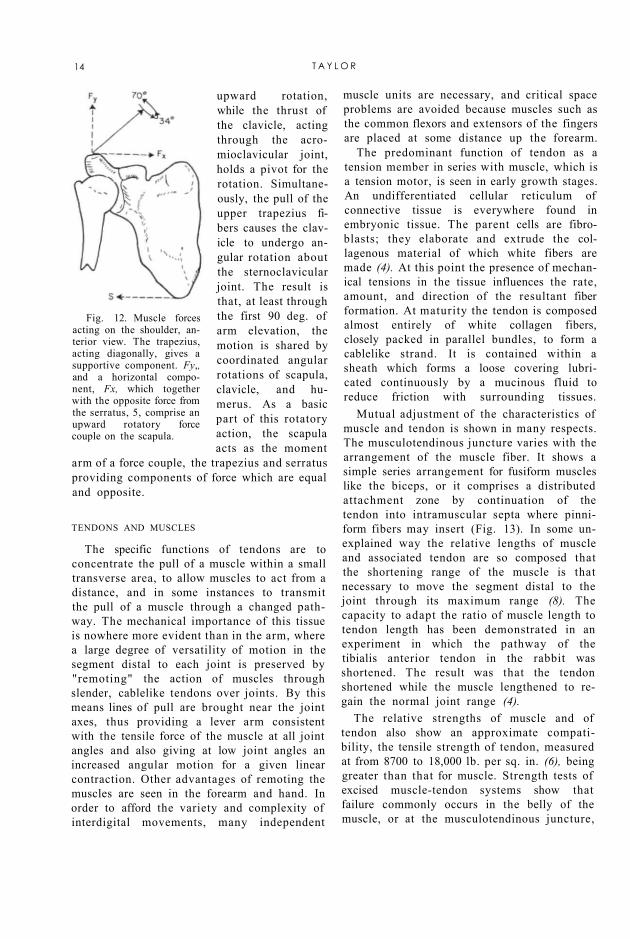
Fig. 11. Force couples at the elbow. Tensile forces in biceps and brahialis are associated with equal, opposite, and parallel forces through the joint.
Members of Mechanical Systems The second principal feature of bones, that
of serving as rigid members in a complex of mechanical systems, is the one that has engaged the most attention. It is surprising that the simple lever concepts of Archimedes have persisted in anatomy and kinesiology texts to the present day. Thus, the forearm-flexor system is said to act as a third-class lever, the extensor system as a first-class lever. Although these assertions are of course true, both of these systems are, in the more complete language of Newtonian mechanics, parts of force-couple systems in which equal and opposite components of force are transmitted through the bones and joints (Fig. 11). Elft-man (7) has emphasized this view. The magnitude of the couple is given by the product of the force (either of the equal but opposite forces) and the distance between them, which also is numerically equal to the torque of the muscle force. The concept of the couple calls attention to the existence of the equal and opposite forces in joints and emphasizes the loads placed upon them by muscular work.
Another and more complicated application of the couple is seen in scapular rotation. Here, as described by Inman el al. (11) and as
shown in Figure 12, the pull of the lower fibers of the serratus anterior upon the scapula is such as to give it
B I O M E C H A N I C S OF CONTROL 13
upward rotation, while the thrust of the clavicle, acting through the acromioclavicular joint, holds a pivot for the rotation. Simultaneously, the pull of the upper trapezius fibers causes the clavicle to undergo angular rotation about the sternoclavicular joint. The result is that, at least through the first 90 deg. of arm elevation, the motion is shared by coordinated angular rotations of scapula, clavicle, and humerus. As a basic part of this rotatory action, the scapula acts as the moment
arm of a force couple, the trapezius and serratus providing components of force which are equal and opposite.
Fig. 12. Muscle forces acting on the shoulder, anterior view. The trapezius, acting diagonally, gives a supportive component. Fy,, and a horizontal component, Fx, which together with the opposite force from the serratus, 5, comprise an upward rotatory force couple on the scapula.
TENDONS AND MUSCLES
The specific functions of tendons are to concentrate the pull of a muscle within a small transverse area, to allow muscles to act from a distance, and in some instances to transmit the pull of a muscle through a changed pathway. The mechanical importance of this tissue is nowhere more evident than in the arm, where a large degree of versatility of motion in the segment distal to each joint is preserved by "remoting" the action of muscles through slender, cablelike tendons over joints. By this means lines of pull are brought near the joint axes, thus providing a lever arm consistent with the tensile force of the muscle at all joint angles and also giving at low joint angles an increased angular motion for a given linear contraction. Other advantages of remoting the muscles are seen in the forearm and hand. In order to afford the variety and complexity of interdigital movements, many independent
muscle units are necessary, and critical space problems are avoided because muscles such as the common flexors and extensors of the fingers are placed at some distance up the forearm.
The predominant function of tendon as a tension member in series with muscle, which is a tension motor, is seen in early growth stages. An undifferentiated cellular reticulum of connective tissue is everywhere found in embryonic tissue. The parent cells are fibroblasts; they elaborate and extrude the collagenous material of which white fibers are made (4). At this point the presence of mechanical tensions in the tissue influences the rate, amount, and direction of the resultant fiber formation. At maturity the tendon is composed almost entirely of white collagen fibers, closely packed in parallel bundles, to form a cablelike strand. It is contained within a sheath which forms a loose covering lubricated continuously by a mucinous fluid to reduce friction with surrounding tissues.
Mutual adjustment of the characteristics of muscle and tendon is shown in many respects. The musculotendinous juncture varies with the arrangement of the muscle fiber. It shows a simple series arrangement for fusiform muscles like the biceps, or it comprises a distributed attachment zone by continuation of the tendon into intramuscular septa where pinni-form fibers may insert (Fig. 13). In some unexplained way the relative lengths of muscle and associated tendon are so composed that the shortening range of the muscle is that necessary to move the segment distal to the joint through its maximum range (8). The capacity to adapt the ratio of muscle length to tendon length has been demonstrated in an experiment in which the pathway of the tibialis anterior tendon in the rabbit was shortened. The result was that the tendon shortened while the muscle lengthened to regain the normal joint range (4).
The relative strengths of muscle and of tendon also show an approximate compatibility, the tensile strength of tendon, measured at from 8700 to 18,000 lb. per sq. in. (6), being greater than that for muscle. Strength tests of excised muscle-tendon systems show that failure commonly occurs in the belly of the muscle, or at the musculotendinous juncture,
14 T A Y L O R
or at the bone-tendon juncture, but never exclusively in the tendon itself. Analysis of clinical cases indicates that muscle is still the site of failure even when it is maximally tensed (14). It is clear, then, that of the muscle-tendon combination the tendon is normally always the stronger.
Fig. 13. Muscle fiber patterns. A, Fusiform. B, Bipinniform.
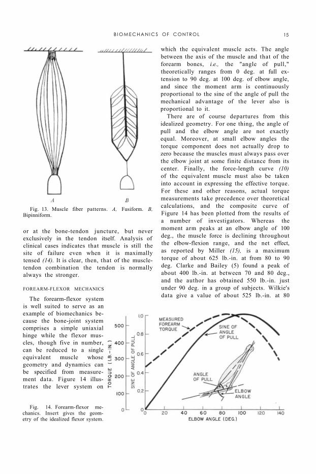
Fig. 14. Forearm-flexor mechanics. Insert gives the geometry of the idealized flexor system.
FOREARM-FLEXOR MECHANICS
The forearm-flexor system is well suited to serve as an example of biomechanics because the bone-joint system comprises a simple uniaxial hinge while the flexor muscles, though five in number, can be reduced to a single equivalent muscle whose geometry and dynamics can be specified from measurement data. Figure 14 illustrates the lever system on
which the equivalent muscle acts. The angle between the axis of the muscle and that of the forearm bones, i.e., the "angle of pull," theoretically ranges from 0 deg. at full extension to 90 deg. at 100 deg. of elbow angle, and since the moment arm is continuously proportional to the sine of the angle of pull the mechanical advantage of the lever also is proportional to it.
There are of course departures from this idealized geometry. For one thing, the angle of pull and the elbow angle are not exactly equal. Moreover, at small elbow angles the torque component does not actually drop to zero because the muscles must always pass over the elbow joint at some finite distance from its center. Finally, the force-length curve (10) of the equivalent muscle must also be taken into account in expressing the effective torque. For these and other reasons, actual torque measurements take precedence over theoretical calculations, and the composite curve of Figure 14 has been plotted from the results of a number of investigators. Whereas the moment arm peaks at an elbow angle of 100 deg., the muscle force is declining throughout the elbow-flexion range, and the net effect, as reported by Miller (15), is a maximum torque of about 625 lb.-in. at from 80 to 90 deg. Clarke and Bailey (5) found a peak of about 400 lb.-in. at between 70 and 80 deg., and the author has obtained 550 lb.-in. just under 90 deg. in a group of subjects. Wilkie's data give a value of about 525 lb.-in. at 80
B I O M E C H A N I C S OF CONTROL 15
deg., measured on himself (22). These variations can be explained as resulting from the effect of a limited sampling of an inherently variable characteristic. Greater consistency probably could be obtained in a larger series of measurements.
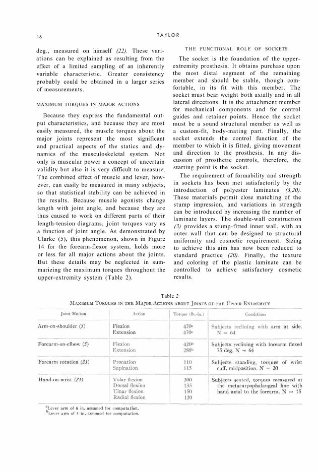
Table 2
MAXIMUM TORQUES IN MAJOR ACTIONS
Because they express the fundamental output characteristics, and because they are most easily measured, the muscle torques about the major joints represent the most significant and practical aspects of the statics and dynamics of the musculoskeletal system. Not only is muscular power a concept of uncertain validity but also it is very difficult to measure. The combined effect of muscle and lever, however, can easily be measured in many subjects, so that statistical stability can be achieved in the results. Because muscle agonists change length with joint angle, and because they are thus caused to work on different parts of their length-tension diagrams, joint torques vary as a function of joint angle. As demonstrated by Clarke (5), this phenomenon, shown in Figure 14 for the forearm-flexor system, holds more or less for all major actions about the joints. But these details may be neglected in summarizing the maximum torques throughout the upper-extremity system (Table 2).
T H E FUNCTIONAL ROLE OF SOCKETS
The socket is the foundation of the upper-extremity prosthesis. It obtains purchase upon the most distal segment of the remaining member and should be stable, though comfortable, in its fit with this member. The socket must bear weight both axially and in all lateral directions. It is the attachment member for mechanical components and for control guides and retainer points. Hence the socket must be a sound structural member as well as a custom-fit, body-mating part. Finally, the socket extends the control function of the member to which it is fitted, giving movement and direction to the prosthesis. In any discussion of prosthetic controls, therefore, the starting point is the socket.
The requirement of formability and strength in sockets has been met satisfactorily by the introduction of polyester laminates (3,20). These materials permit close matching of the stump impression, and variations in strength can be introduced by increasing the number of laminate layers. The double-wall construction (3) provides a stump-fitted inner wall, with an outer wall that can be designed to structural uniformity and cosmetic requirement. Sizing to achieve this aim has now been reduced to standard practice (20). Finally, the texture and coloring of the plastic laminate can be controlled to achieve satisfactory cosmetic results.
16 T A Y L O R
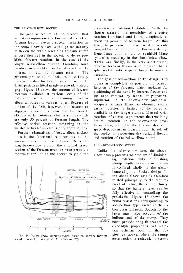
Fig. 15. Below-elbow amputee types, based on average forearm length, epicondyle to styloid. After Taylor (18).
THE BELOW-ELBOW SOCKET
The peculiar feature of the forearm, that pronation-supination is a function of the whole forearm length, places a special limitation on the below-elbow socket. Although for stability in flexion the whole remaining forearm stump is best sheathed in the socket, to do so prohibits forearm rotation. In the case of the longer below-elbow stumps, therefore, some sacrifice in stability can be afforded in the interest of retaining forearm rotation. The proximal portion of the socket is fitted loosely to give freedom for forearm rotation while the distal portion is fitted snugly to provide a stable grip. Figure 15 shows the amount of forearm rotation available at various levels of the natural forearm and that remaining in below-elbow amputees of various types. Because of torsion of the flesh, however, and because of slippage between the skin and the socket, effective socket rotation is lost in stumps which are only 50 percent of forearm length. The effective socket rotation remaining in the wrist-disarticulation case is only about 90 deg.
Further adaptations of below-elbow sockets to suit the functional requirements at the various levels are shown in Figure 16. In the long below-elbow stump, the elliptical cross-section of the forearm near the wrist permits a "screw-driver" fit of the socket to yield the
maximum in rotational stability. With the shorter stumps, the possibility of effective rotation is reduced and is lost completely at about 50 percent of forearm length. At this level, the problem of forearm rotation is outweighed by that of providing flexion stability. Dependence upon a rigid or semirigid hinge system is necessary in the short below-elbow stump, and finally, in the very short stump, effective forearm flexion is so reduced that a split socket with step-up hinge becomes a necessity.
The goal of below-elbow socket design is to regain as completely as possible the control function of the forearm, which includes (a) positioning of the hand by forearm flexion and (b) hand rotation by means of pronation-supination. In the below-elbow prosthesis, adequate forearm flexion is obtained rather easily; rotation is limited to the potential available in the longer stumps. Manual wrist rotation, of course, supplements the remaining natural rotation. In the below-elbow prosthesis, then, control of the terminal device in space depends in fair measure upon the role of the socket in preserving the residual flexion and rotation of the below-elbow stump.
THE ABOVE-ELBOW SOCKET
Unlike the below-elbow case, the above-elbow stump presents no problem of diminish
ing rotation with diminishing stump length because arm rotation is confined wholly to the gleno-humeral joint. Socket design for the above-elbow case is therefore related principally to the requirement of fitting the stump closely so that the humeral lever can be fully effective in controlling the prosthesis. Figure 17 shows the minor variations corresponding to above-elbow type, including the elbow disarticulation. Sockets for the latter must take account of the bulbous end of the stump. They must provide snug fit around the epicondyle projections but maintain sufficient room in the region just above, where the stump cross-section is reduced, to permit
B I O M E C H A N I C S OF C O N T R O L 17
insertion of the stump in the socket. In both the elbow-disarticulation and the standard above-elbow cases, the upper margin of the socket is terminated below the acromion for freedom of movement at the shoulder. In the short above-elbow case, the socket is carried up over the acromion to obtain additional stabilization and suspension from
the shoulder, as required by the very limited stump area.
The control function of the above-elbow socket is twofold. As in the below-elbow case, the socket extends the slump to the next more distal joint and thus gives range and direction to this component upon which the positioning of the still more distal segments depends. But in addition to this feature, the above-elbow socket also has a power function. Through its attachments to shoulders and torso, it provides the forces and displacements needed to produce forearm flexion, terminal-device operation, and elbow lock. To fulfill these functions, the socket must have stable purchase on the stump in both flexion and extension. Hence, for elbow-disarticula
tion and above-elbow types, the socket should continue to the axillary level; for short-above-elbow amputees, it should come up over the acromion (Fig. 17). Finally, medial and lateral rotation of the socket are necessary for further functional positioning. Close fit and good suspension are required to give stability in these actions.
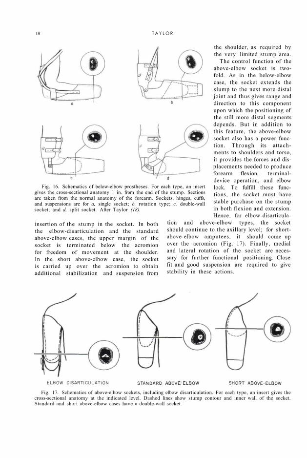
Fig. 16. Schematics of below-elbow prostheses. For each type, an insert gives the cross-sectional anatomy 1 in. from the end of the stump. Sections are taken from the normal anatomy of the forearm. Sockets, hinges, cuffs, and suspensions are for a, single socket; b, rotation type; c, double-wall socket; and d, split socket. After Taylor (18).
Fig. 17. Schematics of above-elbow sockets, including elbow disarticulation. For each type, an insert gives the cross-sectional anatomy at the indicated level. Dashed lines show stump contour and inner wall of the socket. Standard and short above-elbow cases have a double-wall socket.
18 T A Y L O R
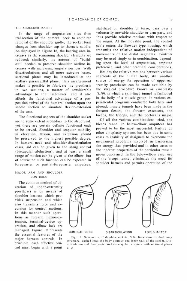
Fig. 18. Schematics of shoulder sockets. Solid lines show residual bony s t ruc ture , dashed lines the body contour and inner wall of the socket. Disarticulation and forequarter sockets may be two-piece with sectional plates at a.
THE SHOULDER SOCKET
In the range of amputation sites from transection of the humeral neck to complete removal of the shoulder girdle, the socket form changes from shoulder cap to thoracic saddle. As displayed in Figure 18, the bearing area increases as the remaining shoulder elements are reduced; similarly, the amount of "build-out" needed to preserve shoulder outline increases with increasing amputation loss. With disarticulations and all more extreme losses, sectional plates may be introduced at the axillary parasagittal plane. This arrangement makes it possible to fabricate the prosthesis in two sections, a matter of considerable advantage to the limbmaker, and it also affords the functional advantage of a preposition swivel of the humeral section upon the saddle section to simulate flexion-extension of the arm.
The functional aspects of the shoulder socket are to some extent secondary to the structural; yet there are certain definite functional ends to be served. Shoulder and scapular mobility in elevation, flexion, and extension should be preserved to the highest possible degree. In humeral-neck and shoulder-disarticulation cases, aid can be given to the shrug control (biscapular abduction), and at least a small range of motion can be given to the elbow, but of course no such function can be expected in forequarter or partial-forequarter amputees.
MAJOR ARM AND SHOULDER CONTROLS
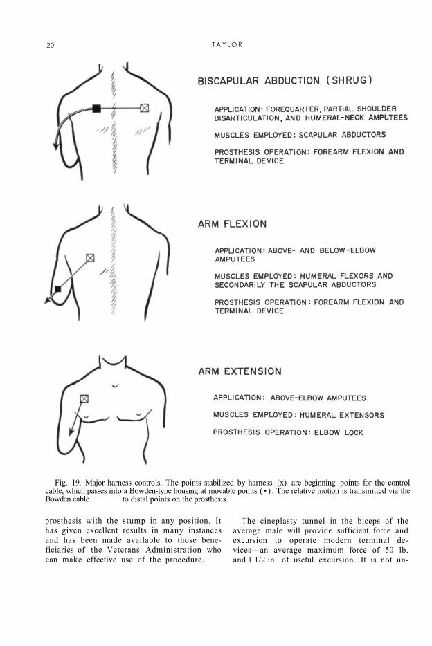
The common method of operation of upper-extremity prostheses is by means of shoulder harness which provides suspension and which also transmits force and excursion for control motions. In this manner such operations as forearm flexion-extension, terminal-device operation, and elbow lock are managed. Figure 19 presents the essential features of the major harness controls. In principle, each effective control must begin with a point
stabilized on shoulder or torso, pass over a voluntarily movable shoulder or arm part, and thus provide relative motions with respect to the origin. At the movable point, the control cable enters the Bowden-type housing, which transmits the relative motion independent of movements of the distal segments. Controls may be used singly or in combination, depending upon the level of amputation, amputee preference, and other practical considerations.
Besides the relative motions between various segments of the human body, still another source of energy for operation of upper-extremity prostheses can be made available by the surgical procedure known as cineplasty (1,19), in which a skin-lined tunnel is fashioned in the belly of a muscle group. In various experimental programs conducted both here and abroad, muscle tunnels have been made in the forearm flexors, the forearm extensors, the biceps, the triceps, and the pectoralis major.
Of all the various combinations tried, the biceps tunnel in below-elbow amputees has proved to be the most successful. Failure of other cineplasty systems has been due in some cases to inability of designers to overcome the mechanical problems involved in harnessing the energy thus provided and in other cases to the inherent properties of the particular muscle group concerned. In the below-elbow case, use of the biceps tunnel eliminates the need for shoulder harness and permits operation of the
B I O M E C H A N I C S OF CONTROL 19
prosthesis with the stump in any position. It has given excellent results in many instances and has been made available to those beneficiaries of the Veterans Administration who can make effective use of the procedure.
Fig. 19. Major harness controls. The points stabilized by harness (x) are beginning points for the control cable, which passes into a Bowden-type housing at movable points ( • ) . The relative motion is transmitted via the Bowden cable to distal points on the prosthesis.
The cineplasty tunnel in the biceps of the average male will provide sufficient force and excursion to operate modern terminal devices—an average maximum force of 50 lb. and 1 1/2 in. of useful excursion. It is not un-
20 T A Y L O R
usual for some individuals to be able to build up the force available to a value in excess of 100 lb., but such a high force normally is not required.
THE NATURE AND OPERATION OF CONTROL SYSTEMS
The Below-Elbow Single-Control System
The single control for the below-elbow amputee is powered by arm flexion to provide terminal-device operation. This control motion, used by the above-elbow amputee also, depends upon a coordinated flexion of the humerus and abduction of the scapula on the amputated side; little shoulder activity is required on the sound side. It is substantially the same motion as that used in normal unilateral reaching. The displacements of humerus and scapula are additive, so that the resulting motion is quite natural. With full Bowden-cable transmissions of power from arm cuff to forearm socket, there is no influence of elbow angle, and the operation is mastered easily by all amputees with stumps of 35 percent or more of normal forearm length.
The Below-Elbow Dual-Control System4
4 Although the terminology commonly used to describe the several control systems could well afford to be better systematized, it is adopted here because it is now so well established throughout the field of prosthetics. One may think of "dual control" as meaning that two control sources are involved in the provision of all necessary functions, but according to convention it means that two functions, specifically elbow flexion and terminal-device operation, are provided by a single control source, the third function, elbow lock, if needed, being managed by an additional control source. Yet "triple control" (page 22) in the accepted sense means not that three functions are furnished by a single control source but that three control sources are used to provide three functions, one for each.—ED.
In harnessing below-elbow stumps shorter than 35 percent of normal forearm length, it generally is necessary to use an auxiliary type of lift to help the amputee flex the forearm. This procedure is applicable to a split-socket type of prosthesis. It merely is an adaptation of the above-elbow dual-control system (page
22) using a lever loop positioned on the forearm section so that arm flexion may be utilized to assist in forearm lift. The cable housing is split and assembled so that when the arm is flexed the elbow will flex. The elbow hinge has no locking mechanism, the short below-elbow stump being used to stabilize the forearm. Normally, sufficient torque is available about the elbow axis to give adequate stability in all usable ranges.
In prescribing for a new amputee with this level of amputation, it might be advisable first to have the amputee try a split-type prosthesis without the below-elbow dual-control system. If, at time of initial checkout, the amputee cannot lift his forearm, or if he complains of painful contact with his stump, then of course the dual system is indicated. After the assist lift has been worn for some time, the remaining muscles of the stump may have hypertrophied, in which case the amputee might be able to discard the dual system and convert to the below-elbow single control.
The Below-Elbow Biceps-Cineplasty System
Force and excursion provided by the biceps muscle tunnel are harnessed by inserting into the tunnel a cylindrical pin of a nontoxic material and attaching a cable to each end of the pin. As in the other types of control systems, the Bowden-cable principle is employed to maintain a constant effective distance between the source of energy and the mechanism to be operated, regardless of relative motions occurring between body segments. In order that conventional terminal devices may be employed, it is necessary to join the two cables before attachment to the mechanism. Several devices for making this coupling are available commercially.
Suspension of the socket is provided by an arm cuff, which is attached to the socket by any of the various hinges normally used in fabrication of below-elbow prostheses. The arm cuff is fashioned in such a manner that forces tending to pull the prosthesis from the stump are absorbed by the condyles of the elbow rather than by the muscle tunnel.
B I O M E C H A N I C S OF CONTROL 21
The Above-Elbow Dual-Control System In above-elbow amputees, the humeral
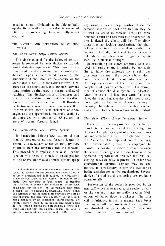
stump furnishes the motive power for the three operations of the prosthesis—flexion of the forearm, operation of the terminal device, and management of the elbow lock. The first two operations are so linked mechanically that a single control motion, arm flexion, produces either terminal-device operation or forearm flexion, depending on whether the elbow is locked or unlocked (Fig. 20). Although the control motion by arm flexion in the above-elbow case is similar to that described for the below-elbow amputee, there are several differences. Because the cable passes through a lever loop on the forearm to give torque about the elbow, it is affected by elbow position. As the forearm is flexed, arm-flexion excursion is used up, and the excursion needed to operate the terminal device must come from scapular abduction (shrug), as in shoulder cases. Typically, the above-elbow amputee manages a full range of free forearm flexion by a normal arm-flexion movement. But in the elbow-angle range of from 90 to 135 deg., with elbow locked for terminal-device operation, he must call upon supplementary excursions from biscapular abduction. With the terminal device at the mouth, practically all operation depends upon shoulder shrug.
In the above-elbow dual-control system, operation of the elbow lock depends upon humeral extension and associated coordinations. When the forearm has been flexed to the position desired, the elbow lock is engaged by the arm-extension movement. Skill is needed
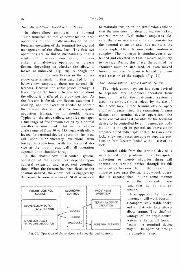
to maintain tension on the arm-flexion cable so that the arm does not drop during the locking control motion. Well-trained amputees elevate the arm moderately to compensate for the humeral extension and thus maintain the elbow angle. The extension control motion is complex. The humerus is simultaneously extended and elevated so that it moves obliquely to the side. During this phase, the point of the shoulder must be stabilized, or even moved forward, and the trapezius is bulged by downward rotation of the scapula (Fig. 21).
Fig. 20. Operation of above-elbow and shoulder dual controls.
The Above-Elbow Triple-Control System The triple-control system has been devised
to separate terminal-device operation from forearm lift. When the dual-control system is used, the amputee must select, by the use of the elbow lock, either terminal-device operation or forearm lifting. By separating forearm flexion and terminal-device operation, the triple control makes it possible for the terminal device to be controlled by an independent body motion. Although in general an above-elbow amputee fitted with triple control has an elbow lock, a few such cases are able to separate prehension from forearm flexion without use of the lock
A control cable from the terminal device is so attached and positioned that biscapular abduction or merely shoulder shrug will operate the terminal device through its full range of prehension. To lift the forearm the amputee uses arm flexion. Elbow-lock operation is accomplished in the same manner
as in the dual-control system, that is, by arm extension.
It is apparent that this arrangement will work best with a comparatively stable socket and a relatively long above-elbow stump. The chief advantage of the triple-control system is that at full forearm flexion the terminal device may still be operated through its complete range.
22 T A Y L O R
Fig. 21. Coordinated control motions for elbow lock. Simultaneously the humerus is both extended (a) and abducted (b) while the shoulder is depressed (c) and the trapezius is bulged (d) by downward rotation of the scapula.
The Shoulder Dual-Control System
In the absence of the humeral lever, the shoulder becomes the major power source, biscapular abduction controlling both forearm and terminal device in the dual-control system. The control path courses horizontally across the scapulae, and either opposite-axilla loop or basic chest-strap harness (page 46) captures the action satisfactorily. The combination afforded by the dual principle also is illustrated in Figure 20.
The shoulder amputee has a special difficulty in obtaining the combination of full forearm flexion and terminal-device operation because, unlike the above-elbow amputee, who can add the excursions of humeral flexion and scapular abduction, he must obtain all movement from biscapular abduction. Shoulder amputees with broad shoulders and wide chests usually achieve this action satisfactorily; others must accept the limitation of partial terminal-device operation at full forearm flexion. Partial-shoulder and fore-quarter amputees must depend upon the sound shoulder entirely, and in this case the action range of the terminal device typically is limited to not more than 90 deg. of forearm flexion.
In shoulder amputees, operation of the elbow lock must be managed by various special arrangements. The waist control, utilizing shoulder elevation; the perineal strap, based
on relative motion between shoulders and pelvis; the nudge control, requiring either manual or chin operation; extreme shoulder flexion on the sound side; and extension of the shoulder on the amputated side complete the array of known feasible possibilities. It is evident that with this class of amputees control motions will be slower and deliberately sequential. They are therefore necessarily more noticeable and awkward.
The Shoulder Triple-Control System
The harness required for the triple-control shoulder-disarticulation system consists of a chest strap for forearm flexion, a waist strap to operate the elbow lock, and an opposite-shoulder loop for prehension. The amputee must have excellent scapular abduction and must be able to separate it from extreme opposite-shoulder shrug, and he must have available good shoulder elevation on the amputated side. The chief advantage of the triple control in the shoulder-disarticulation case is identical to that of the triple control in the above-elbow case, namely, that the terminal device may be operated fully in the vicinity of the mouth. To operate the prosthesis from an extended position, the amputee first produces biscapular abduction, thus raising the forearm. Then, with the forearm held in place, he elevates the shoulder on the amputated side to lock the elbow. To operate the terminal device, he then flexes the sound shoulder. Excursion for terminal-device operation is thus unaffected by forearm flexion.
Unfortunately this system must be restricted to humeral-neck and shoulder-disarticulation cases. For lack of sufficient excursion on the amputated side, it is unlikely that a forequarter amputee would be able to use triple control.
MECHANICAL APPLICATION OF THE MAJOR CONTROLS
To elucidate practical amputee biomechanics, it is necessary to refer to several aspects of the connecting mechanism between amputee and prosthesis in the power-transmission system. Of first importance are the proximal retainers, which are located at the
B I O M E C H A N I C S OF CONTROL 23
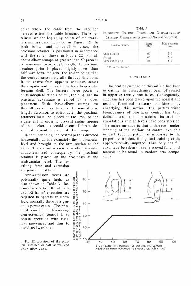
point where the cable from the shoulder harness enters the cable housing. These retainers are the beginning points of the transmission systems indicated in Figure 19. In both below- and above-elbow cases, the proximal retainer is positioned in accordance with the ratios shown in Figure 22. For all above-elbow stumps of greater than 50 percent of acromion-to-epicondyle length, the proximal retainer point is placed slightly lower than half way down the arm, the reason being that the control passes naturally through this point in its course from opposite shoulder, across the scapula, and thence to the lever loop on the forearm shell. The humeral lever power is quite adequate at this point (Table 3), and no practical advantage is gained by a lower placement. With above-elbow stumps less than 50 percent as long as the normal arm length, acromion to epicondyle, the proximal retainers must be placed at the level of the stump end in order to prevent undue tipping of the socket, as would occur if forces developed beyond the end of the stump.
In shoulder cases, the control path is directed horizontally at approximately the midscapular level and brought to the arm section at the axilla. The control motion is purely biscapular abduction, and consequently the proximal retainer is placed on the prosthesis at the midscapular level. The resulting force and excursion are given in Table 3.
Arm-extension forces are potentially quite high, as also shown in Table 3. Because only 2 to 6 lb. of force and 1/2 in. of excursion are required to operate an elbow lock, normally there is a generous power excess. The principal concern in harnessing arm-extension control is to obtain operation with minimal movement and thus to avoid awkwardness.
Fig. 22. Location of the proximal retainer for both above- and below-elbow cases.
CONCLUSION
The central purpose of this article has been to outline the biomechanical basis of control in upper-extremity prostheses. Consequently, emphasis has been placed upon the normal and residual functional anatomy and kinesiology underlying this service. The particularized biomechanics of prosthesis control has been defined, and the limitations incurred in amputations at high levels have been stressed. The major message is that a thorough understanding of the motions of control available to each type of patient is necessary to the proper prescription, fitting, and training of the upper-extremity amputee. Thus only can full advantage be taken of the improved functional features to be found in modern arm components.
24 T A Y L O R
LITERATURE CITED 1. Alldredge, Rufus H., Verne T. Inman, Hyman
Jampol, Eugene F. Murphy, and August W. Spittler, The techniques of cineplasly, Chapter 3 in Klopsteg and Wilson's Human limbs and their substitutes, McGraw-Hill, New York, 1954.
2. Carlyle, L. C, Using body measurements to determine proper lengths of artificial arms, Memorandum Report No. 15, Department of Engineering, University of California (Los Angeles), 1951.
3. Carlyle, Lester, Fitting the artificial arm, Chapter 19 in Klopsteg and Wilson's Human limbs and their substitutes, McGraw-Hill, New York, 1954.
4. Clark, W. E. Le Gros, The tissues of the body; an introduction to the study of anatomy, 3rd ed., Clarendon Press, Oxford, 1952.
5. Clarke, H. Harrison, and Theodore L. Bailey, Strength curves for fourteen joint movements, J. Assoc. Phys. & Ment. Rehab., 4(2):12 (1950).
6. Cronkite, Alfred Eugene, The tensile strength of human tendons, Anat. Rec, 64:173 (1936).
7. Elftman, H , Skeletal and muscular systems: structure and function, in Medical Physics, O. Glasser el al., eds., Vol. I, p. 1420, Year Book Publishers, Inc., Chicago, 1944.
8. Haines, R. W., On muscles of full and of short action, J. Anat., 69:20 (1934).
9. Hollinshead, W. H., Functional anatomy of the limbs and back; a text for students of physical therapy and others interested in the locomotor apparatus, Saunders, Philadelphia, 1951.
10. Inman, Verne T., and H. J. Ralston, The mechanics of voluntary muscle, Chapter 11 in Klopsteg and Wilson's Human limbs and their substitutes, McGraw-Hill, New York, 1954
11. Inman, V. T , J. B. deC M. Saunders, and L. C. Abbott, Observations on the function of the shoulder joint, J. Bone & Joint Surg., 26:1 (1944).
12. Koch, John C, The laws of bone architecture, Am. J. Anat., 21:177 (1917).
13. Lewis, Warren H., ed., Gray's anatomy of the human body, 24th ed. revised, Lea and Febiger, Philadelphia, 1942.
14. McMaster, Paul E., Tendon and muscle ruptures; clinical and experimental studies on the causes and location of subcutaneous ruptures, J. Bone & Joint Surg., 15:705 (1933).
15. Miller, D. P., A mechanical analysis of certain lever muscles in man, Ph.D. dissertation, Graduate School, Yale University, New Haven, Conn., 1942.
16. Newman, R. W., and R. M White, Reference anthropometry of Army men, Report No. 180, Quartermaster Climatic Research Laboratory, Lawrence, Mass., 1951.
17. Steindler, Arthur, Kinesiology of the human body tinder normal and pathological conditions, Charles C Thomas, Springfield, Ill., 1955.
18. Taylor, Craig L., The biomechanics of the normal and of the amputated upper extremity, Chapter 7 in Klopsteg and Wilson's Human limbs and their substitutes, McGraw-Hill, New York, 1954.
19. Taylor, Craig L., Control design and prosthetic adaptations to biceps and pectoral cineplasly, Chapter 12 in Klopsteg and Wilson's Human limbs and their substitutes, McGraw-Hill, New York, 1954.
20. University of California (Los Angeles), Department of Engineering, Manual of upper extremity prosthetics, R. Deane Aylesworth, ed., 1952.
21. Unpublished data, UCLA. 22. Wilkie, D. R., The relation between force and velocity
in human muscle, J. Physiol., 110:249 (1949)
B I O M E C H A N I C S OF C O N T R O L 25