the black post has a coil inside which produces a constantly-changing magnetic field around it. this...
TRANSCRIPT

The black post has a coil inside which produces a constantly-changing magnetic field around it.
This constantly changing magnetic field induces a current to form in the circular aluminum rings which surround it.
This current forms its own magnetic field – which opposes (pushes against!) to one formed by the black post.
Why doesn’t the bottom ring “work”?

FIGURE 25-1. When a wire is moved in a magnetic field, an electric current flows in the wire, but only while the wire is moving. The direction of the current flow depends on the direction the wire is moving through the field. The arrows indicate the direction of conventional current flow.

FIGURE 25-2. The right-hand rule can be used to find the direction of the forces on the charges in a conductor that is moving in a magnetic field.

FIGURE 25-3. Schematic of amoving coil microphone. The aluminum diaphragm is connected to a coil in a magnetic field. When sound waves vibrate the diaphragm, the coil moves in the magnetic field, generating a current proportional to the sound wave.


FIGURE 25-4. An electric current is generated in a wire loop as the loop rotates (a). The cross-sectional view (b) shows the position of the loop when maximum current is generated. The numbered positions correspond to the numbered points on the graph in Figure 25-5.


FIGURE 25-6. Alternating current generators transmit current to an external circuit by way of a brush slip-ring arrangement (a). The alternating current varies with time (b).

ELECTRICIANS Immediate openings! Resid'l journeyman/ foreman, rough & finish. Top wages & bnfts – start at $45,000 for Journeyman. Fax resume 916 294-0168 or apply in person 11855 White Rock Road Rancho C, 916-294-0140
Published to the Web on Sun, 04/17/05
Real ad from Sacamento, CA!


FIGURE 25-7. The magnet approaching the coil causes an induced current to flow. Lenz's law predicts the direction of flow shown.

Lenz’s Law
FIGURE 25-9. As the current in the coil increases from left to right, the EMF generated by the current also increases.

Back-EMF can be explained another way. As Faraday showed, EMF is induced whenever a wire cuts lines of magnetic flux. Consider the coil of wire shown in Figure 25-9. The current through the wire in-creases as we move from left to right. Current generates a magnetic field, shown by magnetic field lines. As the current and magnetic field increase, new lines are created. As the lines expand, they cut through the coil wires, generating an EMF to oppose the current changes. This induction of EMF in a wire carrying changing current is called self-inductance. The size of the EMF is proportional to the rate at which flux lines cut through the wires. The faster you try to change the current, the larger the opposing EMF, and the slower the current change. If the current reaches a steady value, the magnetic flux is constant, and the EMF is zero. When the current is decreased, an EMF is generated that tends to prevent the reduction in magnetic flux and current.

FIGURE 25-10. For a transformer, the ratio of input voltage to output voltage depends upon the ratio of the
number of turns on the primary to the number of turns on the secondary.
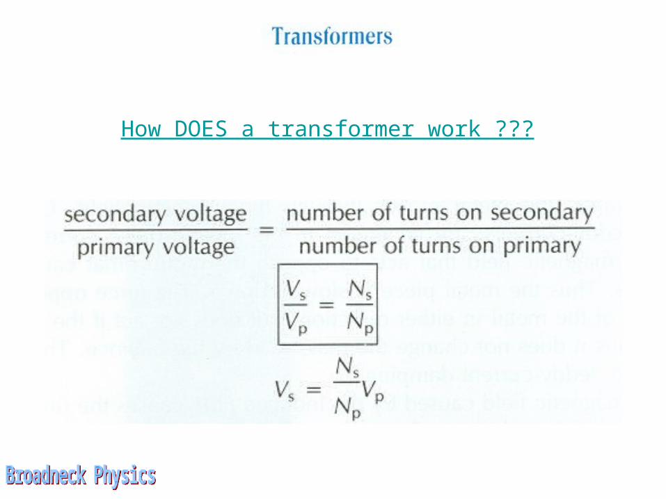
How DOES a transformer work ???


FIGURE 25-11. If the input voltage is connected
to the coils on the left, with the larger number of
turns, the transformer functions as a step-down transformer. If the input
voltage is connected at the right, it is a step-up
transformer.

FIGURE 25-12. Transformers are used to reduce voltages to consumer levels at the points of use.