the bose lifestyle 25 series ii systemproducts.bose.com/pdf/customer_service/owners/og_ls25.pdf ·...
TRANSCRIPT

The Bose® Lifestyle® 25 Series II System
Owner’s Guide
October 29, 2001
AM196575_05_V.pdf

2 October 29, 2001 AM196575_05_V.pdf
Safety Information
WARNING: To reduce the risk of fire or electric shock, do not expose the system to rain ormoisture.
CAUTION
These CAUTION marks may be located on the back panel and bottom of your Lifestyle®
music center and the bottom panel of your Acoustimass® module:
The lightning flash with arrowhead symbol, within an equilateral triangle, is intended to alertthe user to the presence of uninsulated dangerous voltage within the system enclosure thatmay be of sufficient magnitude to constitute a risk of electric shock.
The exclamation point within an equilateral triangle, as marked on the system, is intended toalert the user to the presence of important operating and maintenance instructions in thisowner’s guide.
CAUTION: To prevent electric shock, match wide blade of plug to wide slot, insert fully.
Class 1 laser productThis compact disc player is classified as a CLASS 1 LASER product. The CLASS 1 LASER
PRODUCT label is located on the bottomof the unit.
CAUTION: Use of controls or adjustments or performance ofprocedures other than those specified herein may result in hazardous radiation exposure. Thecompact disc player should not be adjusted or repaired by anyone except properly qualifiedservice personnel.
Class B emissions limitsThis Class B digital apparatus meets all requirements of the Canadian Interference-CausingEquipment Regulations.
BatteriesPlease dispose of used batteries properly, following any local regulations. Do not incinerate.
Additional safety informationSee the additional instructions on the Important Safety Information page enclosed with thisowner’s guide.
Please read this owner’s guidePlease take the time to follow this owner’s guide carefully. It will help you set up and operateyour system properly, and enjoy all of its advanced features. Save your owner’s guide forfuture reference.
Product manufactured under license from Dolby Laboratories. “Dolby” and the double-D symbol are trademarks ofDolby Laboratories.
CLASS 1 LASER PRODUCTKLASSE 1 LASER PRODUKTLUOKAN 1 LASER LAITEKLASS 1 LASER APPARAT
CAUTIONRISK OF ELECTRICAL SHOCK
DO NOT OPEN
CAUTION: TO REDUCE THE RISK OF ELECTRIC SHOCK,DO NOT REMOVE COVER (OR BACK).
NO USER-SERVICABLE PARTS INSIDE.REFER SERVICING TO QUALIFIED PERSONNEL.
AVISRISQUE DE CHOC ÉLECTRIQUE
NE PAS OUVRIR
ATTENTION : POUR RÉDUIRE LE RISQUE DE DÉCHARGEÉLECTRIQUE, NE RETIREZ PAS LE COUVERCLE (OU
L’ARRIÈRE). IL NE SE TROUVE ÀL’INTÉRIEURAUCUNEPIÈCE POUVANT ÊTRE RÉPARÉE PARL’USAGER.S’ADRESSER À UN RÉPARATEUR COMPÉTENT.

AM196575_05_V.pdf October 29, 2001 a
Important Safety Instructions
1. Read these instructions – for all componentsbefore using this product.
2. Keep these instructions – for future reference.3. Heed all warnings – on the product and in the
owner’s guide.4. Follow all instructions.5. Do not use this apparatus near water or
moisture – Do not use this product near abathtub, washbowl, kitchen sink, laundry tub, in awet basement, near a swimming pool, or any-where else that water or moisture are present.
6. Clean only with a dry cloth – and as directedby Bose® Corporation. Unplug this product fromthe wall outlet before cleaning.
7. Do not block any ventilation openings.Install in accordance with themanufacturer’s instructions – To ensurereliable operation of the product and to protect itfrom overheating, put the product in a positionand location that will not interfere with its properventilation. For example, do not place the producton a bed, sofa, or similar surface that may blockthe ventilation openings. Do not put it in a built-insystem, such as a bookcase or a cabinet that maykeep air from flowing through its ventilationopenings.
8. Do not install near any heat sources, suchas radiators, heat registers, stoves or otherapparatus (including amplifiers) that pro-duce heat.
9. Do not defeat the safety purpose of thepolarized or grounding-type plug. A polar-ized plug has two blades with one widerthan the other. A grounding-type plug hastwo blades and a third grounding prong. Thewider blade or third prong are provided foryour safety. If the provided plug does not fitin your outlet, consult an electrician forreplacement of the obsolete outlet.
10. Protect the power cord from being walkedon or pinched, particularly at plugs, conve-nience receptacles, and the point wherethey exit from the apparatus.
11. Only use attachments/accessories speci-fied by the manufacturer.
12. Use only with the cart, stand, tripod,bracket or table specified by themanufacturer or sold with theapparatus. When a cart is used,use caution when moving thecart/apparatus combination toavoid injury from tip-over.
13. Unplug this apparatus during lightningstorms or when unused for long periods oftime – to prevent damage to this product.
14. Refer all servicing to qualified service person-nel. Servicing is required when the apparatushas been damaged in any way: such as power-supply cord or plug is damaged; liquid hasbeen spilled or objects have fallen into theapparatus; the apparatus has been exposed torain or moisture, does not operate normally, orhas been dropped – Do not attempt to service thisproduct yourself. Opening or removing covers mayexpose you to dangerous voltages or other hazards.Please call Bose to be referred to an authorizedservice center near you.
15. To prevent risk of fire or electric shock, avoidoverloading wall outlets, extension cords, orintegral convenience receptacles.
16. Do not let objects or liquids enter the product –as they may touch dangerous voltage points orshort-out parts that could result in a fire or electricshock.
17. See product enclosure for safety relatedmarkings.
Information about products thatgenerate electrical noise
If applicable, this equipment has been tested and foundto comply with the limits for a Class B digital device,pursuant to Part 15 of the FCC rules. These limits aredesigned to provide reasonable protection againstharmful interference in a residential installation. Thisequipment generates, uses, and can radiate radiofrequency energy and, if not installed and used in accor-dance with the instructions, may cause harmful interfer-ence to radio communications. However, this is noguarantee that interference will not occur in a particularinstallation. If this equipment does cause harmful interfer-ence to radio or television reception, which can bedetermined by turning the equipment off and on, you areencouraged to try to correct the interference by one ormore of the following measures:
• Reorient or relocate the receiving antenna.
• Increase the separation between the equipment andreceiver.
• Connect the equipment to an outlet on a differentcircuit than the one to which the receiver is connected.
• Consult the dealer or an experienced radio/TV techni-cian for help.
Note: Unauthorized modification of the receiver or radioremote control could void the user’s authority to operatethis equipment.This product complies with the Canadian ICES-003 ClassB specifications.
22

En
gli
sh
b October 29, 2001 AM196575_05_V.pdf
Important Safety Instructions
Antenna groundingExample of antenna grounding as per National ElectricalCode, ANSI/NFPA 70.
Note to CATV system installerThis reminder is provided to call the CATV systeminstaller’s attention to Article 820-40 of the NEC (of USA)that provides guidelines for proper grounding. In particu-lar, it specifies that the cable ground shall be connectedto the grounding system of the building, as close to thepoint of cable entry as is practical.
18. Use proper power sources – Plug the product intoa proper power source, as described in the operatinginstructions or as marked on the product.
19. Avoid power lines – Use extreme care wheninstalling an outside antenna system to keep fromtouching power lines or circuits, as contact withthem may be fatal. Do not install external antennasnear overhead power lines or other electric light orpower circuits, nor where an antenna can fall intosuch circuits or power lines.
20. Ground all outdoor antennas – If an externalantenna or cable system is connected to thisproduct, be sure the antenna or cable system isgrounded. This will provide some protection againstvoltage surges and built-up static charges.Section 810 of the National Electrical Code ANSI/NFPA No. 70 provides information with respect toproper grounding of the mast and supportingstructure, grounding of the lead-in wire to an antennadischarge unit, size of grounding conductors,location of antenna-discharge unit, connection togrounding electrodes, and requirements for theground electrode. Refer to the antenna groundingillustration on this page.
Antenna lead in wire
Antenna discharge unit(NEC Section 810-20)
Grounding conductors(NEC Section 810-21)
Power service groundingelectrode system(NEC ART 250, Part H)
Ground clamps
Ground clamp
Electric serviceequipment
©2001 Bose Corporation,The Mountain, Framingham, MA01701-9168 USA255805 AM Rev.00 JN10494
22

AM196575_05_V.pdf October 29, 2001 3
Contents
Where to find…Setting Up
Before you begin ........................................................................................................... 4Unpacking the carton ................................................................................................... 5Selecting the locations for your Lifestyle® 25 Series II system ..................................... 6Connecting the speakers and Lifestyle® music center .................................................. 9Connecting your home theater components to the Lifestyle® 25 system ................... 12Connecting the antennas ............................................................................................ 16Installing the batteries in the remote control .............................................................. 17Setting radio channel spacing for dual voltage and 120V systems ............................ 17
Operating Your Lifestyle® 25 SystemTurning on the music center ....................................................................................... 18The music center display ............................................................................................ 18The music center controls .......................................................................................... 19The Lifestyle® 25 remote control ................................................................................. 19The system controls .................................................................................................... 20Additional system controls ......................................................................................... 21Listening to your Lifestyle® 25 system ........................................................................ 22Operating the special features .................................................................................... 23Chimes ........................................................................................................................ 23Listening to digital sound ............................................................................................ 24Listening to compact discs ......................................................................................... 24Listening to the radio .................................................................................................. 27Using the system with external components .............................................................. 28
Maintaining Your Lifestyle® 25 SystemFine-tuning your system ............................................................................................. 29Using two listening zones ........................................................................................... 30Changing the house code settings ............................................................................. 32Taking care of your Lifestyle® 25 system .................................................................... 33Troubleshooting .......................................................................................................... 34Warranty period .......................................................................................................... 35Customer service ........................................................................................................ 35
Product InformationTechnical information.................................................................................................. 36Accessories................................................................................................................. 36
Index ................................................................................................................................. 37Bose® Corporation .................................................................................... inside back cover
For your recordsSerial numbers are located on the bottom of the music center and the bottom panel of theAcoustimass® module.
Music center serial number:______________________________________________________
Acoustimass module serial number: ______________________________________________
Dealer name: __________________________________________________________________
Dealer phone: _______________________ Purchase date: ___________________________
We suggest you keep your sales slip and warranty card together with this owner’s guide.

4 October 29, 2001 AM196575_05_V.pdf
Setting Up
Before you beginThank you for purchasing the Bose® Lifestyle® 25 Series II system. This complete audio homeentertainment system offers superb sound, elegance, technology, and simplicity for musicand home theater. Your system is fully compatible with digital program material and includes:
• A Lifestyle® music center with built-in AM/FM radio and six-disc CD changer
• Inputs for two video sound sources, a digital sound source, and a tape deck (or otherauxiliary source)
• Capability for operating two listening zones
• Powered Acoustimass® speakers with a hideaway Acoustimass module and five cubespeaker arrays
• An easy-to-use remote control
Realism and impactYour Lifestyle® 25 Series II home theater system is equipped with an all new Videostage®
decoder that uses digital signal processing. The result is increased surround sound realismand impact both for movie soundtracks and music recordings. Built-in Dolby Digital decodingof inputs from DVD, digital TV, next-generation cable boxes, and satellite receivers provides“5.1” capability – up to five discrete audio channels directed into five independent cubespeaker arrays, plus rich bass sound from the Acoustimass module. The Videostage decoderprocesses analog formats, as well as two or even single-channel PCM and Dolby Digitalbitstreams, and helps to deliver the acoustic experience of the movies right in your home.
CompatibilityYour system is fully compatible with:
• Digital-audio bitstreams. Look for the symbol 1 or the terms Dolby Digital orPCM on DVD-Video discs. Your Lifestyle® 25 Series II system cannot process MPEG-2or DTS digital bitstreams.
• Surround-sound sources such as VCRs, stereo TVs, cable boxes and satellitereceivers. Videostage decoding directs stereo information to the surround channels, sothe sound of stereo broadcasts and rented or recorded tapes can approach that ofyour DVD discs.
• Surround-encoded analog or digital audio signals. Look for the terms Surround orDolby Surround, or the symbol 3 on tapes and discs, or the word “surround”preceding a TV broadcast.
• Stereo program material from TV, FM, CD, and cassette. Videostage decodingdelivers five channels, even when the original source contained only one or two.
• Monaural program material. Videostage decoding can process a one-channelprogram into five-channel sound and direct the result to five independent speakers.Dialogue remains locked on-screen, while music and ambient effects fill the room.
Automatic sound level monitoring and controlYour enjoyment of movies at home is enhanced by Digital Dynamic Range® compression. Thistechnology automatically monitors and adjusts the volume to allow you to hear soft sounds,particularly dialogue, and to prevent you from being overwhelmed by a loud special effect(e.g., a crash or explosion). This feature is especially useful for late night movie viewing – iteliminates the need for you to constantly adjust the volume level. (See pages 22-23.)

AM196575_05_V.pdf October 29, 2001 5
Setting Up
• Lifestyle® music center• AC power (mains) pack*• FM antenna• AM loop antenna• Antenna base• Remote control• 3 AA batteries• Acoustimass module• 5 cube speaker arrays• AC power (mains) cord*• Audio input cable• 5 speaker cables
(3 front and 2 surround)• 8 self-adhesive rubber feet• Stereo cable• CD magazine• Lifestyle® system CD• Test CD
* Power cord and pack shown above are USA/Canada versions.Dual voltage systems include 1 power cord, 1 adapter , and 2 power packs.The power cords and packs for Europe, UK/Singapore, and Australia are shown below.
UK/SingaporeEurope Australia
Unpacking the cartonCarefully unpack your system. Save all packing materials for possible future use. Theoriginal packing materials provide the safest way to transport your Lifestyle® 25 system. Ifany part of the product appears damaged, do not attempt to use the system. Notify Bose®
or your authorized Bose dealer immediately.
Check to be sure your Lifestyle® 25 system contains the parts identified in Figure 1.
Note: Find the serial numbers on the bottom panel of the Acoustimass® module and thebottom of the music center. Then write them on your warranty card and in the spacesprovided on page 3.
CAUTION: Ensure the three shipping screws on the bottom of the music center areremoved before turning on the system.
WARNING: The Acoustimass module weighs 33 pounds (15 kg). Use good liftingpractice to avoid injury.
WARNING: To avoid danger of suffocation, keep the plastic bags out of the reach ofchildren.
Figure 1
What comes with yourLifestyle® 25 Series II system:
Surround speaker cables(orange connectors)
Front speaker cables(blue connectors)
AAbatteries
AC power pack
5 cube speaker arrays
AC power cord
Rubberfeet Stereo cable
Lifestyle® system CD
FM antenna
AM loopantenna
Audio input cable
Lifestyle® music center
Acoustimassmodule
Antennabase
Remote control
Test CD
CD magazine
®
Treble
Bass
®
THE BOSESPECIAL EDITION LIFESTYLE
MUSIC SYSTEM CD
®
®

6 October 29, 2001 AM196575_05_V.pdf
Setting Up
Selecting the locations for your Lifestyle® 25 Series II systemWhen you place your speakers according to the guidelines below, a combination of reflectedand direct sound provides the audio atmosphere of a home theater. You may experiment withthe placement and orientation of the cubes to produce the sound most pleasing to you. Formore discussion of speaker placement and room acoustics, see “Fine-tuning your system”on page 29.
Speaker locationsFollow these guidelines to select locations that provide the maximum home theater effectfrom your Lifestyle® 25 system (Figures 2 and 3).CAUTION: Choose a stable and level surface for your speakers. Vibration can cause thecube speakers to move, particularly on smooth surfaces like marble, glass, or highly polishedwood. If you are placing the center speaker on top of the television, use the smaller of the twosets of rubber feet provided. You may obtain additional rubber feet (part no. 178321), free ofcharge, by contacting Bose® Customer Service (see listings on the inside back cover).
Left and right front speakersThe sound from the left and right front speakers should seem to appear at the edge of thepicture, so that the acoustic image is close to the size of the visual image (Figure 2).1. Place the cubes so that they line up with the center of the TV screen.2. Place them up to 3 feet (1 m) from the edge of the TV screen.
We recommend a maximum distance of 3 feet (1 m) so that the sound does not becometoo separated from the picture. You may wish to vary this distance based on room condi-tions and personal preference. The front cables allow the cube speakers to be placed upto 20 feet (6.1 m) from the Acoustimass module.
3. Direct one cube of each array forward. Direct the other cube toward the wall or in adifferent direction to create reflected sound. (See the illustration of reflected sound pat-terns in Figure 3.)
Note: The cube speakers are magnetically shielded so you can place them close to theTV without affecting picture quality.
Center speakerThe sound from the center speaker should appear to come directly from the center of thepicture (Figure 2). The center speaker cable allows up to 20 feet (6.1 m) distance from theAcoustimass module.1. Place the center speaker directly above or below the center of the TV screen, or at the
closest convenient location.2. Align the speaker with the front of the TV screen (not pushed to the back of the TV).3. Direct each of the cubes slightly away from center, to create a wider area of direct sound
(Figure 3).
Note: If you put the speakers in a bookcase unit, be sure to place each one at the frontedge of the shelf. Placing speakers in an enclosed space can change the tonal quality of thesound. This effect is minimized if the shelves are filled with books.

AM196575_05_V.pdf October 29, 2001 7
®
Left front Right front
Center
Leftsurround
Rightsurround
Setting Up
Figure 2
Recommended front speakerlocations
Surround speakersThe surround (rear) speakers create an area of sound around the listener. Place them in theback half of your room. Direct the cubes so that you cannot pinpoint the exact location of thesound source (Figure 3). The surround cables allow up to 50 feet (15.2 m) distance from theAcoustimass® module.
Figure 3
Speaker placement
1. Place the speakers at ear height or higher, if possible.
2. Adjust the rear surround speakers to direct the sound to the front and back of the listener.
Acoustimassmodule
CenterLeftfront
Rightfront
8 October 29, 2001 AM196575_05_V.pdf
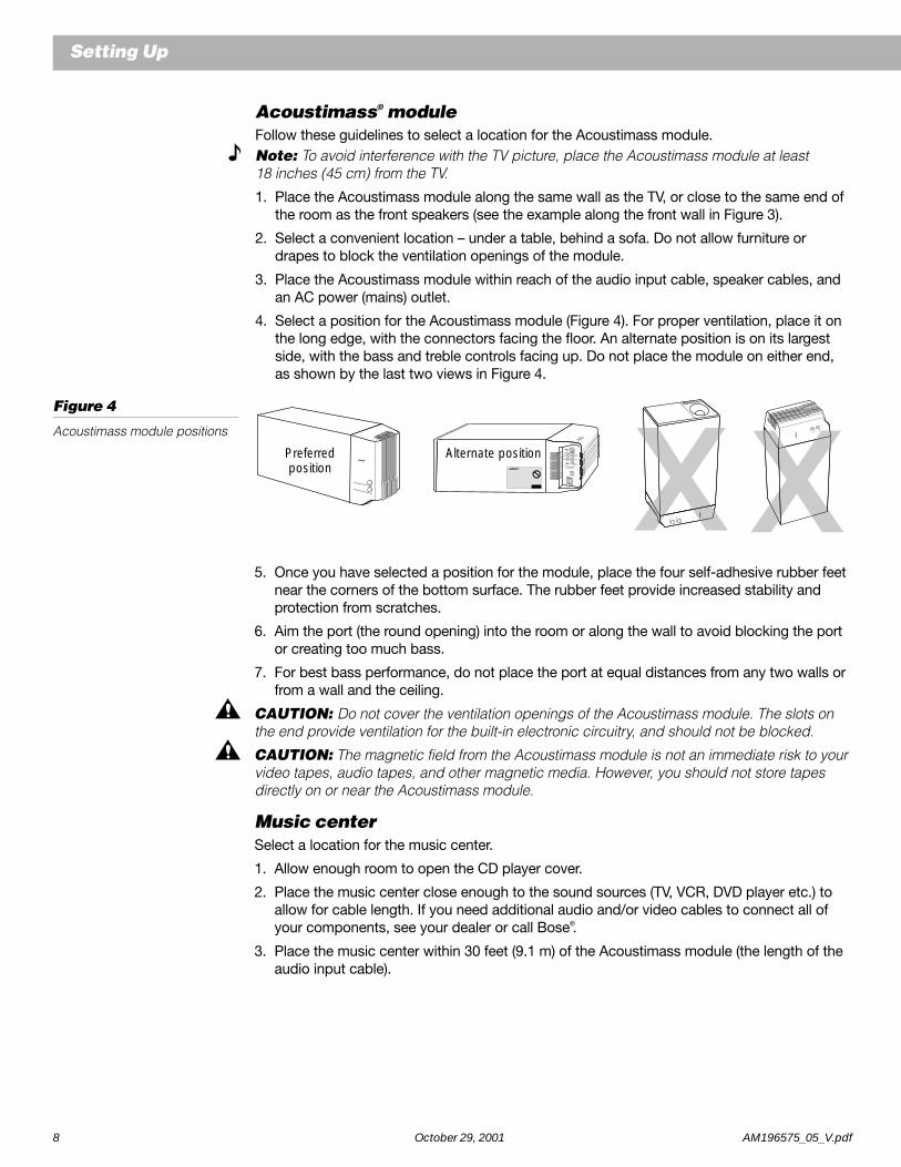
Acoustimass® moduleFollow these guidelines to select a location for the Acoustimass module.Note: To avoid interference with the TV picture, place the Acoustimass module at least18 inches (45 cm) from the TV.
1. Place the Acoustimass module along the same wall as the TV, or close to the same end ofthe room as the front speakers (see the example along the front wall in Figure 3).
2. Select a convenient location – under a table, behind a sofa. Do not allow furniture ordrapes to block the ventilation openings of the module.
3. Place the Acoustimass module within reach of the audio input cable, speaker cables, andan AC power (mains) outlet.
4. Select a position for the Acoustimass module (Figure 4). For proper ventilation, place it onthe long edge, with the connectors facing the floor. An alternate position is on its largestside, with the bass and treble controls facing up. Do not place the module on either end,as shown by the last two views in Figure 4.
Figure 4
Acoustimass module positions
®
Treble
Bass
Preferredposition
RIGHTFRONT
RIGHTREAR
CENTER
OUTPUTS TOCUBE SPEAKERS
LEFTFRONT
LEFTREAR
®
Alternate position
®
®®
Setting Up
5. Once you have selected a position for the module, place the four self-adhesive rubber feetnear the corners of the bottom surface. The rubber feet provide increased stability andprotection from scratches.
6. Aim the port (the round opening) into the room or along the wall to avoid blocking the portor creating too much bass.
7. For best bass performance, do not place the port at equal distances from any two walls orfrom a wall and the ceiling.
CAUTION: Do not cover the ventilation openings of the Acoustimass module. The slots onthe end provide ventilation for the built-in electronic circuitry, and should not be blocked.
CAUTION: The magnetic field from the Acoustimass module is not an immediate risk to yourvideo tapes, audio tapes, and other magnetic media. However, you should not store tapesdirectly on or near the Acoustimass module.
Music centerSelect a location for the music center.
1. Allow enough room to open the CD player cover.
2. Place the music center close enough to the sound sources (TV, VCR, DVD player etc.) toallow for cable length. If you need additional audio and/or video cables to connect all ofyour components, see your dealer or call Bose®.
3. Place the music center within 30 feet (9.1 m) of the Acoustimass module (the length of theaudio input cable).

AM196575_05_V.pdf October 29, 2001 9
Setting Up
Connecting the speakers and Lifestyle® music centerOnce you have selected locations for your music system, connect the speakers.CAUTION: Make sure all components are unplugged from the power outlet before youbegin hooking up the system.
Connecting the cube speaker arrays to the Acoustimass®
moduleEach speaker cable contains two wires. The wire marked with a red collar is positive (+) andthe plain one is negative (–). These wires match the positive (red) and negative (black) termi-nals on the back of each speaker. To lengthen the cable, use heavy-duty RCA extensioncables or splice in 18-gauge or thicker cord (connecting + to + and – to –). To purchasecables, see your dealer or electronics store, or call Bose® customer service.
Note: The surround cables are joined together for your convenience, providing an easy-to-use cable for connecting the surround speakers. To run the cables in different directions fromthe Acoustimass module, simply pull apart the cables as needed.
1. Match the correct cable to the corresponding speaker location.
• Front speaker cables have blue connectors at one end, with L, R, or C molded into theconnectors. The red collars on the + wire are labeled LEFT, RIGHT, and CENTER.
• Surround speaker cables have orange connectors at one end, with L or R molded intothe connectors. The red collars on the + wire are labeled LEFT and RIGHT.
2. Connect the wire end of one speaker cable to the terminals on the rear of the matchingcube speaker array.a. Press the terminal tab on the back of the cube array to insert the marked wire into the
red terminal and the plain wire into the black terminal. Release the tab to secure thewire.
b. Repeat this step for each of the five cube speaker arrays. (See Figure 5.)
Figure 5
Speaker cable connections tothe cube speaker array
CAUTION: Make sure no strands of wire from any terminal touch any other terminal.Bridged wires create short circuits that affect proper operation of your system.
3. Connect each cable to the corresponding jack on the Acoustimass module.a. Plug the blue connectors into the matching left front, center, and right front jacks.b. Plug the orange connectors into the matching left surround and right surround jacks.

10 October 29, 2001 AM196575_05_V.pdf
L R
TAPE IN
L R
TAPE OUT
RIGHTRIGHT
CENTER
OUTPUTS TOCUBE SPEAKERS
LEFT
LEFT
FRONTSURROUND
AUDIO
INPUT
Leftsurroundspeaker
Rightsurroundspeaker
Centerspeaker
Left frontspeaker
Right frontspeaker
Setting Up
Right-angleconnectorinto AUDIO
INPUT
Audioinputcable
AC power jack
To digital signalsource
AC power packMulti-pin connector into SPEAKER ZONE 1
Connecting the Acoustimass® module to the Lifestyle® musiccenterConnect the Acoustimass module to the music center with the audio input cable (Figure 6).
1. Plug the small black multi-pin connector (flat side facing up) into the jack markedSPEAKER ZONE 1 on the rear of the music center.
2. Insert the single right-angle multi-pin connector on the other end of the audio input cableinto the AUDIO INPUT jack on the Acoustimass module. Align the connector at the angleshown in Figure 6.
Note: Connect your digital signal source to the female RCA connector. See “Connectingyour home theater components...” on page 12.
Note: Be sure that each connector is fully inserted into each jack.
3. Extend the audio input cable as much as possible, since it includes an antenna for theremote control.
Note: Refer to “Using two listening zones” on page 30 for information on connecting asecond zone.
Figure 6
Music center and speakerconnections

AM196575_05_V.pdf October 29, 2001 11
Setting Up
230 V115 V
Connecting the Acoustimass® module power (mains) cord1. On a dual voltage system, the voltage selector switch is preset at the factory to be correct
for your area. Check to be sure it is set for the proper voltage (Figure 7). Use 115V forNorth America; 230V for Europe and Australia. In Europe, use the adapter plug provided. Ifyou are in doubt, contact your local electric utility for the appropriate voltage setting.
Figure 7
Dual voltage Acoustimassmodule: voltage selector switchsettings
CAUTION: Make sure the voltage selector switch is set correctly.
2. Plug the small end of the power (mains) cord into the Acoustimass module AC power jack.
Note: Do not plug the AC power cord into a power outlet until all component connectionsare complete.
Connecting the music center AC (mains) power packThe Lifestyle® music center comes with a 120V AC (mains) power pack for use in the USAand Canada or an appropriate 230V or 240V power pack for international use. (See Figures 1and 8.) Dual voltage models include both 120V and 230V power packs.
CAUTION: Be sure to use the correct power pack for your area. Using the wrong one maydamage your power pack or your music center.
• Model PS71, 120V in North America • Model PS72, 230V in Europe• Model PS74, 230V in UK or Singapore • Model PS77, 240V in Australia
Figure 8
The AC power pack(model PS71 shown)
1. Firmly insert the small connector on the end of the AC (mains) power pack cable into theAC POWER jack on the back of the Lifestyle® music center.
2. Make sure that the power pack reaches an AC (mains) outlet.
Note: Do not plug the AC power pack into a power outlet until all component connectionsare complete.

12 October 29, 2001 AM196575_05_V.pdf
Setting Up
Connecting your home theater components to the Lifestyle® 25 systemThere are many possible variations of equipment in a home theater. In addition to theLifestyle® 25 system, a home theater complement typically includes a stereo or mono TV andstereo VCR. In a digital home theater system, the primary source may be a DVD player. Yourhome theater can include many other combinations of equipment, including cable TV,laserdisc players, additional VCRs, and a satellite decoder.
Note: A mono TV only serves as a display for the video, not as a source for the audio.
In order for the Lifestyle® 25 system to provide home theater effects, the program materialmust be in stereo or surround-encoded, and the device playing the material must be stereo.Look for the word “surround” on the tape, CD, or preceding the TV broadcast. To hear stereoor surround sound from encoded video tapes, you must have a stereo (HiFi) VCR. While notall VCRs deliver stereo, all CD, DVD, and nearly all laserdisc players do.
Note: Line level outputs from most VCRs or laserdisc players are fixed. If your VCR, laser-disc player, or other video sound source has fixed and variable outputs, use the fixed out-puts.
Setting up a digital sound sourceConnect a DTV or DVD player’s digital signal directly to the female RCA jack on the audioinput cable. Connect the DVD player’s analog signal output to the AUX inputs. If yourLifestyle® system receives a valid digital signal (including PCM or Dolby Digital bitstreams),this digital sound is used. If no valid digital signal is received, then your system selects theanalog signal being sent to AUX, which is then processed by the Videostage® decoder forexcellent home theater sound. If your digital audio source has an optical connector, you willneed an adapter with an RCA (coaxial) connector. Consult your dealer or contact Bose®.
Note: Ensure the connection between the digital source and the Lifestyle® system is madeusing a 3 to 6 foot (1 to 2 m) standard audio cable or video cable. For longer lengths, use a75 ohm cable.
Figure 9
Music center connectors
Setting up a video sound sourceThe Lifestyle® 25 system has two sets of video sound inputs (Figure 9) for your non-digitalvideo sound sources, such as your TV or VCR.
Note: Your Lifestyle® 25 system includes one 6-foot (1.8 m) stereo cable to connect the right(R) and left (L) audio outputs from a component to the music center inputs. Cables may alsobe supplied with your components. If needed, audio cables are available at many electronicsstores, or call Bose. Most audio cables are color coded. Match red connectors to right (R)jacks and black or white connectors to left (L) jacks.
Non-digital video sound source outputs to VIDEO inputs
DVD analog outputs to AUX inputs
AM196575_05_V.pdf October 29, 2001 13
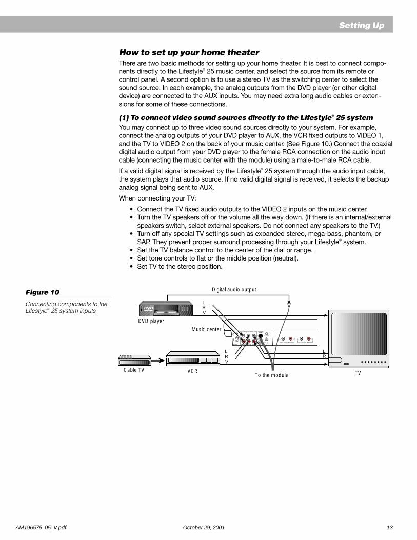
How to set up your home theaterThere are two basic methods for setting up your home theater. It is best to connect compo-nents directly to the Lifestyle® 25 music center, and select the source from its remote orcontrol panel. A second option is to use a stereo TV as the switching center to select thesound source. In each example, the analog outputs from the DVD player (or other digitaldevice) are connected to the AUX inputs. You may need extra long audio cables or exten-sions for some of these connections.
(1) To connect video sound sources directly to the Lifestyle® 25 systemYou may connect up to three video sound sources directly to your system. For example,connect the analog outputs of your DVD player to AUX, the VCR fixed outputs to VIDEO 1,and the TV to VIDEO 2 on the back of your music center. (See Figure 10.) Connect the coaxialdigital audio output from your DVD player to the female RCA connection on the audio inputcable (connecting the music center with the module) using a male-to-male RCA cable.
If a valid digital signal is received by the Lifestyle® 25 system through the audio input cable,the system plays that audio source. If no valid digital signal is received, it selects the backupanalog signal being sent to AUX.
When connecting your TV:
• Connect the TV fixed audio outputs to the VIDEO 2 inputs on the music center.• Turn the TV speakers off or the volume all the way down. (If there is an internal/external
speakers switch, select external speakers. Do not connect any speakers to the TV.)• Turn off any special TV settings such as expanded stereo, mega-bass, phantom, or
SAP. They prevent proper surround processing through your Lifestyle® system.• Set the TV balance control to the center of the dial or range.• Set tone controls to flat or the middle position (neutral).• Set TV to the stereo position.
Figure 10
Connecting components to theLifestyle® 25 system inputs
Setting Up
L R
TAPE IN
L R
TAPE OUT
LR
LRV
LRV
VCRCable TV TVTo the module
Music center
Digital audio output
DVD player

14 October 29, 2001 AM196575_05_V.pdf
Cable TV VCR TV
DVD playerMusic center
Digital audio output
To the module
L R
TAPE IN
L R
TAPE OUT
LLRV R
V
RL Music center
(2) To direct video sound sources through your TVThis is an alternative connection method. (See Figure 11.) If your stereo TV has fixed audiooutputs (the audio signal level doesn’t change) and it allows you to select the source of thesignal (VCR, laserdisc, cable, etc.), then you can:
• Connect your DVD player L and R outputs to the music center AUX inputs.• Connect the DVD video output to one of the video inputs on the TV.• Connect the coaxial digital audio output from your DVD player to the female RCA
connection on the audio input cable (connecting the music center with the module)using a male-to-male RCA cable.
• Connect your home theater components to the TV inputs.• Connect the TV fixed audio outputs to the VIDEO 1 inputs on the music center.• Turn the TV speakers off or the volume all the way down. (If there is an internal/external
speakers switch, select external speakers. Do not connect any speakers to the TV.)• Turn off any special TV settings such as expanded stereo, mega-bass, phantom or
SAP. They prevent proper surround processing through your Lifestyle® system.• Set the TV balance control to the center of the dial or range.• Set tone controls to flat or the middle position (neutral).• Set TV to the stereo position.
Note: If necessary, as a second choice, you can use the variable audio outputs from yourstereo TV. Turn off or disconnect the TV’s speakers and leave the volume control up – close tothe maximum setting.
Note: If you connect your stereo VCR through your stereo TV, do not use coaxial cable.Instead, connect the VCR L and R audio outputs to the TV L and R audio inputs to ensureproper stereo and surround sound.
Figure 11
Connecting componentsthrough your TV
Setting Up

AM196575_05_V.pdf October 29, 2001 15
Setting Up
About the video sourceYour TV is the display for the video (picture) signal. Thus, the video signal must be connecteddirectly to the TV. Do not connect it to the Lifestyle® 25 system.
Note: For assistance with video connections between your DVD player and/or VCR and TV,see your video components manuals.
Note: There is no video signal input (usually a yellow-coded jack) on the music center. TheVIDEO INPUT jacks are for audio from a video source.
Other connectionsUse standard RCA audio cables to connect other components to your Lifestyle® musiccenter, matching the red connector to R (right) and the white (or black) connector to L (left).
You can use a Y-adapter (available at electronics stores) to connect a mono source.
Tape deckTo use an external recorder (analog audio cassette, MD, or digital audio tape), connect theinputs (REC) of the recorder to the music center’s TAPE OUT jacks. Connect the outputs(PLAY) from the recorder to the music center’s TAPE IN jacks.
Laserdisc player or additional CD changerTo use one of these components, connect its audio outputs to the music center VIDEO 1,VIDEO 2, or AUX (if not used for a digital source) jacks, matching the red plug to R (right) andblack or white plug to L (left).
TurntableTo connect a turntable, you need a phono preamplifier (with RIAA equalization). You can orderthe appropriate model from Bose® by calling 1-800-367-4008 and asking for part number252603. Connect the audio outputs of the phono preamplifier to the music center VIDEO 1,VIDEO 2, or AUX (if not used for a digital source) jacks, matching the red plug to R (right) andblack or white plug to L (left).
Note: The Lifestyle® 25 system cannot turn on or turn off a connected component.

16 October 29, 2001 AM196575_05_V.pdf
Setting Up
AM antenna jack
FM antenna jack
Figure 13
The FM dipole antenna
Figure 14
The AM loop antenna
Connecting the antennasThe rear panel of your Lifestyle® music center provides connections for AM and FM antennas(Figure 12). Unwind each antenna’s wires. Antennas provide better reception when their wiresare not bundled.
Note: Outdoor antennas may be used with the music center antenna connections. To installan outdoor antenna, consult a qualified installer. Follow all safety instructions.
Figure 12
The antenna connections
FM antenna connections1. Plug the antenna connector into the FM ANTENNA jack on the back of the Lifestyle® music
center.
2. Spread out the antenna arms. Experiment with both the placement and the angle of thisantenna to provide optimum FM reception.
AM antenna connectionsNote: To install the AM antenna on a wall, follow the instructions enclosed with the antenna.
1. Plug the AM antenna connector into the AM ANTENNA jack on the back of the Lifestyle®
music center.
2. Stand the loop antenna on the base, following the instructions enclosed with the antenna.
3. Move the loop part of the antenna as far as possible but at least 20 inches (50 cm) fromthe music center and at least 4 feet (1.2 m) from the Acoustimass® module. Experimentwith the orientation of the loop for optimum AM reception.
Connecting to a cable radio signalTo connect your system to the FM signal available from some cable TV companies, contactyour cable provider for assistance. The connection is made to the FM 75Ω EXTERNALantenna connector on the back of the system.
CAUTION: Be certain that the installation includes a signal splitter so that only the FM band,not the cable TV band, is transmitted to the system. It is necessary to use a splitter that filtersthe signal to prevent any re-emissions of the TV spectrum through the system.
L R
TAPE IN
L R
TAPE OUT

AM196575_05_V.pdf October 29, 2001 17
Setting Up
Miniature switches
Battery compartment cover
3 AA batteries
Setting radio channel spacing for dual voltage and 120V systemsDual voltage music centers (which include both 120V and 230V power packs) can be set fortwo types of AM and FM channel spacing.
• 10 kHz for AM and 200 kHz for FM (common to North America)
• 9 kHz for AM and 50 kHz for FM (common to Europe)
Your dual voltage music center is preset for North American spacing. Select the channelspacing most appropriate for your area.
To change between North American and European channel spacing:
1. Turn the music center off.
2. Press and hold the ERASE key (on the music center control panel) for three seconds. Thedisplay flashes PROGRAM and indicates US for North American spacing or Euro forEuropean spacing.
3. While holding the ERASE key, press SOURCE SELECT (on the music center controlpanel). The display flashes PROGRAM and the setting changes from US to Euro. Whileholding ERASE, press SOURCE SELECT again to change from Euro to US.
Installing the batteries in the remote control1. Slide open the battery compartment on the back of the remote (Figure 15).
2. Insert 3 AA or IEC-R6 1.5V batteries, or the equivalent, as shown. Match the + and –symbols on the batteries with the + and – markings inside the compartment.
3. Slide the battery compartment cover back into place.
Replace the batteries when the remote control stops operating or its range seems reduced.Alkaline batteries are recommended.
Note: Do not change the settings of the factory-preset miniature switches. See “Changingthe house code settings” on page 32 for information on how to prevent conflicts with otherLifestyle® music systems.
Figure 15
Installing the remote controlbatteries

18 October 29, 2001 AM196575_05_V.pdf
Turning on the music centerPlug the Acoustimass® module power cord into an AC (mains) outlet. Then plug in the musiccenter power pack.
Note: Your speakers will not operate unless all cable and power connections are completedbefore turning on the music center.
You are ready to enjoy your new Lifestyle® system. Open the music center by gently pressingupwards on the bottom of the door (Figure 16).
Refer to the pages that follow for information on operating the music center controls and theLifestyle® remote control.
Play the Test CD, following the instructions on page 24. Listen to the instructions on the CDto verify your system setup.
Note: If your system will be unattended for a few days, you may want to unplug your musiccenter to prevent a neighbor’s Lifestyle® remote control or your pets from accidentally turningit on. Also see “Changing the house code settings” on page 32.
The music center displayThis music center display (Figure 17) provides information on the music center functions.
Figure 17
The music center display
Operating Your Lifestyle® 25 System
Zone 1 or 2indicator
No discindicator
Muteindicator
Random play alldiscs or randomplay one discindicator
CD track andAM/FM presetnumber display
Playindicator
Pauseindicator
Disc indicators
Settinghousecodesindicator
Stopindicator
CD elapsed timeand AM/FMstation frequencyindicator
Sourceindicators
Figure 16
Opening the music center door

AM196575_05_V.pdf October 29, 2001 19
The Lifestyle® remote controlThe advanced radio-frequency remote control works from anywhere within most typesof home construction. Its radio wave signals pass through walls and floors to reach the music center. Simply press the desired button. You do not need to aim the remote at themusic center.
Note: Some types of buildings create “dead spots” where the remote will not operate. Simplymove the remote a foot or two and try again. You can also move the music center a few feet toa location with better remote response.
Figure 19 shows the layout of the remote control.
Special buttons on the remote control select the speaker mode (5, 3, or 2 speakers), andadjust the surround (rear) volume and the center speaker volume.
Figure 19
The remote control
Figure 18
The music center controls ONOFF VOLUME
STORE/ IPLAY/PAUSE
SOURCESELECT
ERASE
SKIP
NEXT DISCTUNE
I
The music center controlsThe music center function keys are described on page 20. Use the following special musiccenter keys to tune the radio, set station presets, and scan a CD (Figure 18).
TUNE / - Lowers or raises the frequency setting of the radio (stations). In CD mode,initiates a fast scan of the current CD.
STORE or ERASE - Adds or removes radio station presets. For instructions, see page 27.Also used for changing channel spacing (page 17) and house codes (page 32).
Operating Your Lifestyle® 25 System

20 October 29, 2001 AM196575_05_V.pdf
Operating Your Lifestyle® 25 System
AMFM
AUX
CD
1VIDEO
2VIDEO
TAPE
MUTE
MUTEALL
OFF
ON
Note: For information on controlling the system from different zones, see “Using two listening zones” on page 30.
SOURCESELECT
/ II
/ II
SKIP
SKIP
ONOFF
SKIPSKIP
The system controls
Function
VIDEO 1 - Selects a video sound source connected to the VIDEO 1 inputs,and turns the system on. (See page 22.)
VIDEO 2 - Selects a video sound source connected to the VIDEO 2 inputs,and turns the system on.
AUX - Selects the DVD player (or other component connected to the AUXinputs) and turns the system on. Selects digital audio, if present.
CD - Selects the built-in CD changer and turns the system on.
AM/FM - Selects the radio and turns the system on to the previously selectedstation. When the radio is on, switches between AM and FM.
TAPE - Selects a tape deck or other component connected to the TAPE inputs,and turns the system on.
SOURCE SELECT - Turns the system on to the previously selected soundsource. When on, changes the source in this sequence CD, FM, AM, VIDEO 1,VIDEO 2, AUX, TAPE, CD.
STOP - Stops the CD player. After 20 minutes, the system shuts off.
PAUSE - Pauses play of the CD. After a 20-minute pause, changes to STOP.
PLAY - Begins play of the CD.
RANDOM (or SKIP plus SKIP ) - In CD mode, begins random play ofall tracks on all discs. Pressed again, begins random play of tracks on thecurrent disc. Pressed again, cancels random play.
SKIP - Selects the previous CD track, or the previous preset radio station.Held down, initiates backward scan (CD) or seek (tuner) function.
SKIP - Selects the next CD track, or the next preset radio station. Helddown, initiates forward scan (CD) or seek (tuner) function.
NEXT DISC - Advances to play the next disc loaded in the CD magazine.
VOLUME \ - Raises or lowers the system volume.
MUTE - Silences the speakers in the selected zone. Also restores volume tomuted speakers in the selected zone.
MUTE ALL - Silences all speakers currently playing. Also restores sound tospeakers silenced by the MUTE ALL key.
ON/OFF - Turns the system on and off.
RANDOM
Music centerRemote control

AM196575_05_V.pdf October 29, 2001 21
Operating Your Lifestyle® 25 System
Remote control
SURROUND
STEREO+CENTER
STEREO
SURROUND
Additional system controls
Function
SURROUND• Press and release to select SURROUND (5-speaker) mode for all sources.• Press and hold for 3 seconds to engage (1 chime) or disengage (2 chimes) simulated surround for monoaural program sources.• Press and hold for 8 seconds to restore (3 chimes) factory settings for speaker mode and surround volume level.
STEREO+CENTER• Press and release to select STEREO+CENTER (3-speaker) mode for all sources.• Press and hold for 8 seconds to restore (3 chimes) factory settings for speaker mode and center
volume level.
STEREO• Press and release to select STEREO (2-speaker) mode for all sources.• Press and hold to engage (1 chime) or disengage (2 chimes) Digital Dynamic Range® compression.
SURROUND + / –• In SURROUND (5-speaker) mode, raises or lowers volume of surround speakers.• In STEREO+CENTER (3-speaker) mode, raises or lowers volume of center speaker.• In STEREO (2-speaker) mode, + selects the SURROUND mode.
Note: The adjustments made with SURROUND + and – will be remembered even if you select another speaker mode.
Note: If you set the master volume level very high or very low, a built-in feature automaticallyresets it to a moderate threshold level the next time the system is turned on.
Note: To restore all factory default settings, turn power off then on, press and hold theSURROUND
SURROUND (5-speaker) until you hear the 3-chime confirmation tone, then press and
hold the STEREO+CENTER STEREO+CENTER
(3-speaker) until you hear the 3-chime confirmation tone.

22 October 29, 2001 AM196575_05_V.pdf
Operating Your Lifestyle® 25 System
Listening to your Lifestyle® 25 systemYour Lifestyle® 25 system uses digital signal processing to bring even greater realism andimpact to both movies and music recordings. Built-in Dolby Digital decoding delivers up to5.1 discrete audio channels (i.e., five for the independent cube speaker arrays and one forrich bass from the Acoustimass® module) from DVD, digital TV, next-generation cable boxes,and satellite receivers. With analog formats, as well as for two-channel PCM and DolbyDigital bitstreams, Videostage® decoding directs stereo information to the surround channels,so the sound of stereo broadcasts and rented or recorded tapes can approach that of yourDVD discs.
In addition, Videostage decoding processes a one-channel program and directs five-channelsound to five independent speakers. Dialogue remains locked on-screen, while music andambient effects fill the room to increase your listening enjoyment.
Your Lifestyle® 25 system offers the option of listening in 5, 3, or 2-speaker mode. The systemturns on in SURROUND (5-speaker) mode. For most video material (mono, stereo, or sur-round), listening in 5 or 3-speaker mode helps anchor the dialogue to the picture whileproviding a fuller sound.
Using enhanced mode for movie soundtracksPressing VIDEO 1, VIDEO 2, or AUX turns the system on in enhanced mode, with bass andtreble settings specially designed for proper playback of movie soundtracks. Press the samebutton (VIDEO 1, VIDEO 2, or AUX) again to alternate between enhanced mode for moviesand standard mode for other listening. Pressing TAPE turns the system on in standard mode.Press TAPE again to alternate between enhanced mode for movies and standard mode forother listening.
Note: Enhanced mode provides more bass and less treble, as is specified for properplayback of movie sound.
Digital Dynamic Range® compressionDigital Dynamic Range® compression automatically adjusts the volume to allow you to hearsoft sounds (particularly dialogue) and to prevent you from being overwhelmed by a loudspecial effect (e.g., an explosion). This feature is engaged when you turn on the system, butyou may turn it on (one chime) or off (two chimes) using the STEREO
STEREO
(2-speaker) button.
Using simulated surround for mono movie materialBose® Videostage decoding can process a one-channel program into five-speaker sound –directing the signals so that dialogue remains locked on-screen, while music and ambienteffects fill the room. You experience a surround sensation, providing extra enjoyment whenyou watch older (i.e., pre-stereo) movies. This feature can be used for mono TV, FM, and AMprograms. Press the SURROUND
SURROUND (5-speaker) button to turn it on (one chime) or off (two
chimes). This feature is automatically engaged when a Dolby Digital bitstream indicates that itcontains a mono program.

AM196575_05_V.pdf October 29, 2001 23
Operating Your Lifestyle® 25 System
Operating the special featuresPlease see the previous page for a more detailed explanation of these special features.
Enhanced mode
When you select The mode is To change thisVIDEO 1, VIDEO 2, or AUX Enhanced Press the same button again
TAPE Standard Press the same button again
CD or AM/FM Standard Not applicable: You cannot selectenhanced mode for CD or AM/FM
Digital Dynamic Range® compression
When you select Compression is To change thisVIDEO 1, VIDEO 2, or AUX ON Press and hold the STEREO
STEREO
(2-speaker)button until two chimes are heard
CD, AM/FM, or TAPE OFF Press and hold the STEREO STEREO
(2-speaker)button until one chime is heard
Simulated surround (monaural into 5 speakers)
When your audio source is Simulated surround is To change thisMono Dolby Digital ON Press and hold the SURROUND
SURROUND (5-speaker)
button until two chimes are heard (OFF)
Anything else OFF Press and hold the SURROUND SURROUND
(5-speaker)button until one chime is heard (ON)
To return speaker levels to factory settings
To reset PressCenter speaker level STEREO+CENTER
STEREO+CENTER (3-speaker) button until you hear a 3-note chime
Surround (rear) speakers level SURROUND SURROUND
(5-speaker) button until you hear a 3-note chime
ChimesWhen you hear one or more chimes, it means that one of the system features has been turned on or off.
What the chimes mean
When you hear This means1 chime Simulated surround (monaural into 5 speakers)
or Digital Dynamic Range compression has been turned ON
2 chimes Simulated surround (monaural into 5 speakers)or Digital Dynamic Range compression has been turned OFF
3 chimes Surround speaker level or Center speaker level hasbeen restored to factory default settings

24 October 29, 2001 AM196575_05_V.pdf
Figure 20
Loading a CD665544332211
6 DISK MAGAZINE
665544332211
Listening to digital sound
Turning on the digital audio sourceTurn on the DVD player, DTV, or other digital audio source. Load the DVD disc.
Turning on the system and choosing digital soundPress AUX to turn your system on to play digital sound. If your Lifestyle® system does notreceive a valid PCM or Dolby Digital bitstream, it will automatically select the analog signalconnected to the music center AUX jacks.
Selecting listening materialTo select material with compatible digital-audio bitstreams, look for the terms PCM or DolbyDigital, or the symbol 1 on DVD-Video discs. Your Lifestyle® 25 system cannot processMPEG-2 or DTS digital bitstreams. Make sure a connection is made between your DVDplayer or Digital TV’s digital audio output and your system’s digital audio input.
To select surround-encoded analog or digital audio material, look for the terms Surround orDolby Surround, the symbol 3 on tapes and discs, or the word “surround” preced-ing a TV broadcast. You can listen to any program material in SURROUND (5-speaker) mode,though you may not hear sound from all five speakers all the time. Some monaural and stereomaterials will not cause sound to be directed to the surround speakers. Even with surround-encoded material there are times when no sounds are directed to the surround speakers.
Listening to compact discs
Using the CD changerYou can load up to six compact discs at a time.
Loading discs into the CD magazineHold the magazine, looking at the side with the arrow. Insert up to six discs, label side up(Figure 20). Take care to place only one disc in each slot. Note the slot numbers 1 through 6,from bottom to top, on the front edge window. These numbers correspond to the CD num-bers on the display.
Note: If a disc is upside-down, it does not play. The display shows the word “disc” andflashes the box representing that disc.
CAUTION: Do not insert more than one disc into any slot. Forcing two discs into one slotcould cause them to become stuck, and could damage the discs, the CD magazine, or themusic center.
Operating Your Lifestyle® 25 System

AM196575_05_V.pdf October 29, 2001 25
Ejecting discs from the CD magazinePress the white lever that corresponds to the disc you want to eject. This ejects the disc farenough for you to grasp the edge and remove it from the magazine (Figure 21).
Loading the CD magazine into the music center
Open the music center door. Insert the CD magazine fully into the music center, following thedirection of the arrow on the magazine (Figure 22).
Ejecting the CD magazine from the music center
Press the EJECT button, at the lower left of the magazine slot, to remove the magazine(Figure 23). If a CD is playing, pressing the EJECT button stops the CD, replaces it in themagazine, and ejects the magazine.
Figure 23
The CD magazine EJECTbutton
6 DISC MAGAZINE
654321
EJECT
EJECT button
Figure 22
Loading the CD magazine
6 DISC MAGAZINE
INSERT IN THIS DIRECTION
Operating Your Lifestyle® 25 System
Figure 21
Ejecting a CD

26 October 29, 2001 AM196575_05_V.pdf
Turning on the system and choosing the CD playerPress the CD key on the remote or press SOURCE SELECT on the music center until CD isselected. If the system is already on, use one of these keys to select the CD player. The CDindicator on the display lights. If a CD has been loaded, it begins to play.
Note: Selecting CD turns the system on in SURROUND (5-speaker) mode. PressSTEREO+CENTER
STEREO+CENTER
(3-speaker) or STEREO STEREO
(2-speaker) to change the mode.
CD operationsIf you want to Press
Play or resume play of a CD PLAY, or / II PLAY/PAUSE
Pause a CD PAUSE, or / II PLAY/PAUSE
Stop a CD STOP, or select another source
Go to next track SKIP (forward)
Go to beginning of current track SKIP (reverse) after 4 seconds of track play
Go to previous track SKIP within the first four seconds of the track.After four seconds, press SKIP twice to go to theprevious track. In RANDOM mode, skips to previoustrack played.
Play another disc NEXT DISCIn PLAY mode, selects discs in order, 1 through 6,then back to 1; in RANDOM mode, randomly selectsanother disc. The music center skips empty discslots.
Scan a CD Press and hold SKIP or , or TUNE or
Randomly play tracks on all discs RANDOM, or SKIP plus (on the music center)
Randomly play tracks on one disc RANDOM, or SKIP plus (on the music center),a second time
Cancel random play RANDOM, or SKIP plus (on the music center),a third time; press STOP; or select another source
Note: To prevent excessive wear on the CD mechanism, unattended CD play or randomplay operations change to STOP after 24 hours. If you want to leave the music center playingunattended for longer than 24 hours, you can use the radio.
The music center display provides the following information about the CD changer functions(see sample display in Figure 24):
• Which CD is playing, paused, or stopped, or NONE if no disc is installed
• How much time the current CD has played
• Which track is playing
• If RANDOM ALL DISCS or RANDOM (one disc) is selected
• Which slots have been scanned and have discs loaded
- Numbers in boxes represent discs in slots.
- Empty boxes indicate disc slots that have not yet been scanned by the music center.
- Blank spaces indicate empty slots (or discs that cannot be loaded).
- A flashing box indicates the disc is upside down or cannot be read.
Figure 24
Display of CD playing in zone 1:
Disc 3, track 8, 2 minutes and45 seconds played, 6 CDs areloaded, and random play for alldiscs is selected
Operating Your Lifestyle® 25 System

AM196575_05_V.pdf October 29, 2001 27
Operating Your Lifestyle® 25 System
Listening to the radioTurning the system on and choosing the radioPress the AM/FM key on the remote or the music center to turn your music system on to themost recently heard AM or FM station. The system turns on in SURROUND mode. Selectanother speaker mode, if desired.
Note: If the system is on and the radio is already selected, this key switches between theAM and FM bands.
Tuning
Seeking the strongest stations• Press and hold SKIP (forward) or (reverse) to start seeking. Release the key to stop
at the next strong signal.
• To stop seeking sooner, briefly press SKIP or STOP.• You can seek again without holding down the SKIP key. As soon as the first seek opera-
tion stops, briefly press the SKIP or key.
Switching between AM and FMPress the AM/FM key to switch to the other band.
Manual tuningTo tune to a distant or weak station that the radio cannot seek, use TUNE or on themusic center.
Setting a station presetYour Lifestyle® music center can store up to 25 AM and 25 FM stations in any combination.Note: To allow for different station preferences, you can reserve a group of preset numbersfor each household member. Any station can be assigned to more than one preset number.Or, you can reserve different number groups for different types of stations. For easy refer-ence, you may want to keep a written record of your presets.
1. Lift the music center door.2. Select a radio station you want to store as a preset, either by tuning manually or by
pressing and holding a SKIP key.3. Press the STORE key. The lowest available preset number flashes for three seconds, then
is set and displayed.4. If you prefer a different preset number, while the number is flashing press either SKIP key
to select another available preset number. The preset number is displayed.Note: You cannot store a station in an already-occupied preset location without erasing thatpreset station first (see “Erasing a preset station” below). If you attempt to store more than 25AM or 25 FM stations, the preset display will flash ‘— —’.
Selecting a preset stationOnce you have set station presets, press SKIP or to select the next or the previouspreset station. See Figure 25 for a sample display of a preset FM station.
Erasing a preset station1. Lift the music center door.2. Select the preset station you want to erase.3. Press the ERASE key.
Figure 25
FM display showing a presetstation

28 October 29, 2001 AM196575_05_V.pdf
Using the system with external componentsFollow the instructions on pages 12-15 for connecting components.
Turn on your component directly or by using its remote control. Use the VOLUME or button on the Lifestyle® remote control or music center to raise or lower the volume. Controlall other functions at the source, referring to its owner’s manual, if necessary. To begin, makesure the component is turned on and a tape, CD, DVD, laserdisc, etc. is loaded.
Note: The Lifestyle® 25 system cannot turn a connected component on or off.
Turning the system on and selecting the componentPress the TAPE, AUX, VIDEO 1, or VIDEO 2 button on the remote or press SOURCE SELECTon the music center until the desired component is selected. This turns your system on andselects the component connected to that input. If the system is already on, this buttonselects the component.
Note: Selecting a source turns the system on in SURROUND (5-speaker) mode. PressSTEREO+CENTER
STEREO+CENTER
(3-speaker) or STEREO STEREO
(2-speaker) to change the mode.
The appropriate display indicator lights when the system is on and the component is selected.
Using a video sound sourcePress VIDEO 1 or VIDEO 2 on the remote or SOURCE SELECT on the music center untilVIDEO 1 or 2 appears on the display. This turns your system on in SURROUND (5-speaker)mode and selects the video sound source connected to the VIDEO 1 or 2 jacks.
If your video component is connected to the music center TAPE jacks, press TAPE on theremote or SOURCE SELECT on the music center until TAPE appears on the display. Thisturns your system on in SURROUND (5-speaker) mode and selects the source connected tothe TAPE jacks.
Using enhanced mode for movie soundtracksWhen a movie soundtrack is played in a motion picture theater, its bass and treble arerestored to the original levels intended by the movie’s sound designer. To re-create the sameperformance in your home, your Lifestyle® 25 system’s enhanced mode restores the bass andtreble to these levels when you select VIDEO 1, VIDEO 2, or AUX.
When VIDEO 1, VIDEO 2, or AUX is selected, you can also choose between standard andenhanced modes. The system turns on in enhanced mode for movies. Press the same button(VIDEO 1, VIDEO 2, or AUX) again to change to standard mode. When TAPE is selected, thesystem turns on in standard mode. Press TAPE again to change to enhanced mode formovies.
Note: You may not hear a difference between enhanced and standard modes when listeningto dialogue or other program material that does not have much bass or treble.
Using a tape deckTo record to a connected tape deck, play the source (AM/FM, CD, AUX, VIDEO 1 or 2) youwant to tape. In a 2-zone system, play the source in zone 1. Set the tape deck to record.
Using headphonesFor headphone listening, use the stereo mini headphones jack on the side of the music center(Figure 26). While this jack accepts most headphone models, you can get an adapter atBose® dealers and most electronics stores, if needed.
Connecting headphones silences the speakers connected to SPEAKER ZONE 1.
Operating Your Lifestyle® 25 System
Figure 26
Connecting headphones
®

AM196575_05_V.pdf October 29, 2001 29
Maintaining Your Lifestyle® 25 System
Fine-tuning your systemIn most situations, following the speaker placement guidelines (see pages 6-8) providesexcellent sound quality.
You do not need to adjust tone settings for changes in volume, since Bose® patented signalprocessing technology provides a natural tonal balance over the full range of volume settings.
If desired, you can further fine-tune your system as described below.
Adjusting speaker controlsThe Lifestyle® 25 system TREBLE and BASS controls are located on the Acoustimass®
module (Figure 27). They allow you to adjust the treble (high frequencies) and bass (lowfrequencies). In the normal setting, the dots on each control are in the 12 o’clock position.You can also locate the normal setting by feeling when the control settles into the notch atthis position. Turn the controls clockwise to increase, and counterclockwise to decrease, theamount of treble or bass.
Compensating for room acousticsThe acoustics (sound qualities) of your room can affect the overall sound quality of anyspeaker system. In general, you can reduce many problems with acoustics by the cautioususe of the TREBLE and BASS controls.
Too much or too little trebleRooms with too few sound-absorbing furnishings, especially those with bare floors and walls,may sound overly shrill or “bright.” Turning down the treble control (toward –) decreasestreble sound.
Rooms with a lot of sound-absorbing furnishings, such as upholstered furniture, wall-to-wallcarpet, or heavy drapes, may reduce the treble sound of your system. Moving speakersfarther away from soft furnishings increases treble. You can increase treble sound by slightlyturning up the treble control (toward +).
Too much or too little bassYou can decrease bass sound by turning down the bass control (toward –). To increase bass,turn up the bass control (toward +).
Acoustimass module placement affects the amount of bass you hear. Placing the modulecloser to the corner of the room will increase bass. Moving the module away from the cornerwill decrease bass.
Figure 27
Bass and treble controls
®
Treble
Bass

30 October 29, 2001 AM196575_05_V.pdf
Using two listening zonesThe Lifestyle® 25 system can direct sound from one or two sound sources to two differentlistening areas at the same time. Each listening area, whether a room or a group of rooms(including outdoor areas), is referred to as a zone. By adding powered speakers and asecond remote, you can establish two listening zones (Figure 28).
How zones work• Zones 1 and 2 can play the same or different sound sources at the same time – CD, AM/
FM tuner, TAPE, VIDEO sound, or AUX.
• Only one radio station can be played at a time.
Setting up two zones• The Lifestyle® 25 speakers are set up in zone 1.
• Any combination of rooms and floors in your home can be set up as zones.
• Use an appropriate Lifestyle® system cable to connect a second Bose® powered speakersystem to the SPEAKER ZONE 2 jack on the back of the music center.
• You can also use special adapters to connect an existing stereo system.
• Use a second Lifestyle® system remote control to operate zone 2.
See your dealer or contact Bose for information on obtaining additional powered speakers,remote controls, cables, and adapters for connecting additional equipment.
Setting a second remote for zone 2You need a second remote control, set to ZONE 2, to operate speakers connected to theZONE 2 output.
To set your second remote to control speakers in the second zone, follow these steps:
1. Open the remote control battery cover.2. Locate miniature switch 8 (Figure 29). If it is set down for ZONE 1, slide it up for ZONE 2,
using a paper clip, ballpoint pen, or similar object.3. Make sure the house code switches (1, 2, 3, and 4) match those on your first remote.
(See page 32 for more information on house codes.)4. Replace the battery cover.
ZONE 1 – switch 8 down
2 3 4l
ON
5 6 7 8
K40
ZONE 2 – switch 8 up
2 3 4l
ON
5 6 7 8
K40
Zone 1 remote Zone 2 remote
Figure 28
Example of two listening zones:the Lifestyle® 25 speakers inzone 1 and Acoustimass®
powered speaker system inzone 2
Bedroom
Zone 2
Figure 29
Speaker code switch settings
Livingroom
Zone 1
Maintaining Your Lifestyle® 25 System

AM196575_05_V.pdf October 29, 2001 31
Operating two listening zones
Controlling the zones from the remote controlsTo control two zones, you need to have a remote set to each zone. See instructions onpage 30 for setting a second remote to zone 2.
• You can select and control sources in each zone by commands from its remote control.
• You can control the volume in each zone directly from its remote control.
• You can turn each zone on and off directly from its remote control.
• You can listen to the same source in both zones.
Controlling the zones from the music center control panelTurning two zones on and off from the music center involves a sequence of actions.
• To turn zone 2 on from the music center, press and hold the ON/OFF key. Watch thedisplay to see which zone is on or off. Release the key to keep the option shown.
Holding the ON/OFF key causes this repeating sequence:
zone 1 zone 2First ON OFFSecond ON ONThird OFF ON
• To turn the zones on or off from the music center when both zones are on, press the ON/OFF key for the following sequence:
zone 1 zone 2ON ON
First press OFF ONSecond press OFF OFFThird press ON OFFFourth press OFF OFFAdditional presses zone 1 repeats ON and OFF
• When zone 1 is on (even if zone 2 is also on), the music center keys control zone 1 only.
• When zone 2 is the only zone on, the music center keys control zone 2.
• If you press SOURCE SELECT for FM or AM while zone 2 is playing the other radio band,the band selected in zone 2 flashes on the display. If you do not want to change the bandplaying in zone 2, use SOURCE SELECT to choose another source within two seconds.
The music center display of zone information• When zone 1 or both zones are on, the display shows zone 1 information.
• When only zone 2 is on, the display shows zone 2 information.
Maintaining Your Lifestyle® 25 System

32 October 29, 2001 AM196575_05_V.pdf
Maintaining Your Lifestyle® 25 System
4. Lift the music center door.
5. Turn both zones off.
6. Press and hold the STORE key. The display will begin to flash PROGRAM.
7. While you hold the STORE key and the display is flashing, press any key on the remotecontrol.
• The display stops flashing and momentarily shows PROGRAM to confirm recognition of anew house code.
• The display verifies the house code by lighting four rectangles corresponding to the fourswitch positions (up or down). See the example in Figure 31.
8. Release the STORE key. The system remains off.
9. If you have additional remote controls, change the switches to match those of the firstremote control. It is not necessary to repeat steps 4-8.
Note: To verify your system’s house code, press STORE while the system is off. The displayconfirms the settings of switches 1-4.
Figure 30
Miniature switches for settinghouse codes and zones
Figure 31
Display confirming an exampleof house code setting switch 1up, switches 2, 3, and 4 down
Changing the house code settingsEach Lifestyle® remote control uses a system of matching house codes to communicate withits corresponding music center. If your remote’s commands ever conflict with those ofanother nearby Lifestyle® system, you can easily set a new house code for your system andits remote control(s) by following the procedures below.
1. Open the remote control battery cover and locate the miniature switches (Figure 30).
2. To create a new code, change the position of switches 1, 2, 3, or 4 by moving them in theopposite direction from their current settings. Use a paper clip, ball point pen, or similarobject.
Note: Do not change switches 5, 6, or 7 at this time. The manufacturer’s standard setting isswitch 5 up and switches 6 and 7 down.
3. Replace the battery cover.
2 3 4l
ON
5 6 7 8
K40
House code switches

AM196575_05_V.pdf October 29, 2001 33
Taking care of your Lifestyle® 25 systemThe only maintenance needed is cleaning the system and your compact discs, and replacingremote control batteries.
For information on replacing the remote control batteries see “Install the batteries in the remotecontrol” on page 17.
Handling CDsHandle discs by their edges to prevent fingerprints and scratches (Figure 32).
To remove stains or fingerprints from the surface of a disc, use a soft, lint-free, dry cloth. Wipein straight movements from the center of the disc to the outside (Figure 33). Do not use anychemical products; they can damage the disc.
Do not write on or attach labels to the surface of the disc.
To minimize exposure to dust and dirt, replace discs in their cases after use. Store each discin its case, out of direct sunlight, high temperatures, and humidity.
Cleaning the music centerUse only a soft, dry cloth to clean the outside of the music center.
Do not use any solvents, chemicals, or cleaning solutions containing alcohol, ammonia, orabrasives. Do not allow liquids to spill into any openings. Do not use any sprays near thesystem.
Cleaning the speakersClean the surface of your speakers with a soft, damp cloth. You can use an ammonia-freewindow cleaner on a soft cloth to maintain the finish.
Do not use any sprays near the system. Do not use any solvents, chemicals, or cleaningsolutions containing alcohol, ammonia, or abrasives. Do not allow liquids to spill into anyopenings.
The speaker grille panels require no special care, although you may vacuum them carefully, ifnecessary.
Transporting your music centerTo transport your music center, follow these steps to lock down the CD mechanism.
1. Eject the CD magazine.
2. Make sure the music center is off (all zones).
3. On the music center, press STORE, ERASE, and PLAY/PAUSE at the same time. Thenrelease.
4. Press and hold the EJECT button for 10 seconds. The CD elevator moves into lockeddown position.
5. If you hear the elevator continue to move up and down, wait 10 seconds and then repeatsteps 3 and 4.
The CD mechanism unlocks automatically the next time you select CD.
Maintaining Your Lifestyle® 25 System
Figure 33
Cleaning a CD
Figure 32
Handling a CD

34 October 29, 2001 AM196575_05_V.pdf
Maintaining Your Lifestyle® 25 System
Troubleshooting
Problem What to do
System does not function • Make sure the power connector is inserted securely into the music center, the power cordat all is inserted securely into the Acoustimass® module, and the power pack and power cord are
plugged fully into operating AC wall outlets.• Be sure to select a source (CD, AM/FM, etc.).• Unplug the music center power pack for a minute, then reconnect it. This allows the unit to
reset itself after a power surge or power interruption.• If the system is not responding, press STORE, ERASE, and ON/OFF (on the music center)
at the same time, to reset the system.
No sound • Increase the volume.• Check to see if MUTE is lit on the display. If it is, press the MUTE button on the remote
control to unmute the sound.• Make sure the audio input cable is firmly seated in the music center SPEAKER ZONE 1
jack and the multi-pin connector on the other end is firmly seated in the Acoustimassmodule AUDIO INPUT jack.
• Check speaker connections.• Make sure the digital audio input cable is firmly seated in the music center AUX jack and the
other end of the cable is firmly seated in the connector at the digital source.• Turn the music center off for 10 seconds, then on again, to restore communication between
the music center and the speakers.• Check the connections for any external components. Make sure to select the correct
source for the desired input.• Be sure the CD is placed correctly, label-side up, in the magazine, and the magazine is
inserted properly in the music center.• Disconnect any headphones.• Connect the FM and AM antennas.
No sound from • Make sure the center cube cable is connected at both ends.center speaker • Select STEREO+CENTER
STEREO+CENTER
(3-speaker) or SURROUND SURROUND
(5-speaker) mode.
Too much sound • In STEREO+CENTER (3-speaker) mode, press SURROUND – to decrease center speakerfrom center speaker volume.
• Press and hold the STEREO+CENTER STEREO+CENTER
(3-speaker) button for 10 seconds torestore the factory preset center volume setting.
No sound from • Select SURROUNDSURROUND
(5-speaker) mode.surround speakers • Press SURROUND +.
• Press and hold the SURROUND SURROUND
(5-speaker) button for 10 seconds to restore thefactory preset surround volume setting.
• Make sure the video sound source is stereo and surround-encoded, and the componentused (TV, VCR, DVD or laserdisc player) is stereo.
Surround speakers • In SURROUND (5-speaker) mode, press SURROUND –.are too loud • Make sure that the left and right front speakers are connected to the front speaker jacks
(blue) and the left and right surround speakers are connected to the surround speakerjacks (orange).
• Press and hold the SURROUND SURROUND
(5-speaker) button for 10 seconds to restore thefactory preset surround volume setting.

AM196575_05_V.pdf October 29, 2001 35
Maintaining Your Lifestyle® 25 System
Problem What to do
Remote control • Check batteries and their polarity (+ and –). See page 17.is inconsistent • Operate the remote control closer to the music center.or does not work • Move the remote (or the music center) a few feet to avoid an area of “dead spots.” See
note on page 19.• Make sure the audio input cable is firmly seated, uncoiled, and extended as much as
possible.• Make sure the remote control and music center house codes match. Follow steps 4-8 on
page 32 to match the house code settings.
Unit turns on • Change the house code setting to prevent signals from conflicting with another nearbyand off by itself, Lifestyle® system. See page 32 for instructions on setting the house code.or behaves erratically
Radio does not work • Make sure antennas are connected properly.• Move AM antenna at least 20 inches (50 cm) from the music center.• Adjust antenna position to improve reception.• AM antenna must be upright.• Move antennas farther from TV or other electronic equipment.• You may be in an area of weak signal coverage.
CD does not play • Check to see if the play symbol in the display is lit.• After pressing the CD key, wait a few seconds before pressing PLAY.• Make sure the magazine is properly inserted.• Check to see if there is a disc in the magazine, label-side up. Display shows a flashing box
for a disc that is label-side down or cannot be read.• Eject the magazine and try loading the CD again.• There may be dirt or dust on the CD. Clean the CD. See Figure 33 on page 33.• The disc may be defective. Try another disc.• A display message “E01” indicates a mechanical error. Unplug the music center. Reconnect
power and try again. If “E01” reappears, call Bose® customer service (see inside back coverfor listings).
FM sound is distorted • Adjust antenna position to reduce interference.
FM sound is noisy in • Weak FM stations will produce static in the surround speakers. Press the STEREOsurround mode
STEREO
(2-speaker) button to minimize noise.
Sound is distorted • Make sure speaker cables are not damaged and the connections are secure.• Reduce the output level from any external components connected to the music center.
No tape, CD, VCR, • Check the connections.or TV sound • Make sure the component is turned on.
• Refer to the component owner’s manual.
Warranty periodThe Bose Lifestyle® 25 system is covered by a limited 1-year transferable warranty. Details ofthe warranty are provided on the warranty card that came with your system. Please fill out theinformation section on the card and mail it to Bose.
Customer serviceFor additional help in solving problems, contact Bose customer service. See the inside backcover for Bose Corporation customer service offices and phone numbers.

36 October 29, 2001 AM196575_05_V.pdf
Product Information
Technical information
Music center power packpower ratingUSA/Canada: 120V~ 60 Hz 25VA
Europe: 230V~ 50 Hz 25VA
Australia: 240V~ 50 Hz 25VA
Dual voltage: 120V~ 60 Hz 25VA and230V~ 50 Hz 25VA
Speaker system power ratingUSA/Canada: 120V~ 50/60 Hz 350W
Europe/Australia: 220-240V~ 50/60 Hz 350W
Dual voltage: 115/230V~ 50/60 Hz 350W
Music center inputsTAPE: 2Vrms, maximum
AUX, VIDEO: 2Vrms, maximum
FM antenna: 75ΩAM antenna: 12µH
Power: 12V~, 1.3A
Music center outputsVariable audio: SPEAKER ZONES 1 and 2
Fixed audio: ZONE 1, ZONE 2, TAPE
Headphone: 32Ω minimum impedance
SERIAL DATA: for future use
Zone connector pinout:1: variable left audio2: variable right audio3: fixed left audio4: fixed right audio5: audio ground6: +10V control line7: SMART SPEAKER data8: control line ground (and remote antenna)
Remote control range65 feet (20 m)
DimensionsMusic center
15.5" W x 8.0" D x 2.6" H(39.4 cm x 20.3 cm x 6.6 cm)
Cube speaker
3.1" W x 4.0" D x 6.2" H(7.8 cm x 10.2 cm x 15.7 cm)
Acoustimass® module
23.3" W x 7.5" D x 14.0" H(59.0 cm x 19.0 cm x 35.5 cm)
WeightsMusic center
5.9 lb (2.7 kg)
Cube speaker
2.4 lb (1.1 kg)
Acoustimass module
33 lb (15.0 kg)
Total shipping weight
65 lb (29.5 kg)
FinishMusic center
Aluminum
Cube speakers
Polymer, painted
Acoustimass module
Vinyl veneer, Polymer
AccessoriesTo find out about mounting brackets, stands, CD magazines, additional remote controls,and connecting additional Bose® powered loudspeakers, contact your Bose dealer. Or callBose directly (see inside back cover for phone numbers).
8 7 6
5 4 3
2 1

AM196575_05_V.pdf October 29, 2001 37
Index
AAA 5, 17AC POWER 11AC power cord 5, 11AC power pack 5, 10, 11accessories 36acoustic image 6Acoustimass® module 2-11, 16, 18,
29, 34, 36AM antenna 5, 16, 34, 35, 36AM/FM 4, 20, 22-24, 27, 28, 34analog 4, 12, 13, 15, 22, 24ANTENNA 16antenna 5, 16, 34, 35, 36audio cable 12, 13AUDIO INPUT 10, 34audio input cable 5, 8, 10, 34audio tapes 8Australia 5, 11, 36AUX 12, 13, 20, 22, 28, 30, 36
Bbarrel connector 9BASS 29batteries 2, 5, 17, 33, 35
Ccable 5-12, 14, 34, 35cable box 4, 22cable radio 16cable TV 12, 16Canada 5, 11, 36CD 8, 12, 18-20, 23-28, 30, 33-36CD changer 4, 20, 24, 26CD magazine 5, 20, 24, 25, 33center speaker 6, 10, 23, 34channel spacing 17, 19chimes 21-23cleaning 33coaxial cable 12-14components 11-15, 28, 34, 35connections 9-11, 15, 16, 34, 35controls 2, 8, 13, 14, 19-21, 29, 36cube speakers 4-6, 9, 36customer service 6, 9, 35
Ddamage 5, 24, 35dead spots 19, 35decoder 4, 12digital
audio input 24audio source 4, 24bitstreams 22, 24signal processing 22sound 4, 24display 12, 15, 18, 24-28, 31, 32, 34,35
distorted 35Dolby Digital 4, 12, 22, 24Dolby Surround 4, 24DTS 4, 24DTV 12, 24dual voltage 5, 11, 17, 36DVD 4, 8, 12-14, 24, 28Digital Dynamic Range® compression
4, 21-23
EE01 35EJECT 33eject 25encoded 12, 24enhanced mode 22, 23, 28ERASE 27, 33, 34error 35EU 17Europe 5, 11, 17, 36expanded stereo 13, 14external antenna 16
F5.1 4, 225-speaker 21-24, 26, 28, 34factory preset 11, 17female-to-female adapter 9finish 36five-channel 4, 22fixed 12-14FM 75Ω EXTERNAL antenna 16FM ANTENNA 16FM antenna 5, 16, 36front speaker 5, 6, 8, 10, 34
Hhandling CDs 33headphones 28, 34home theater 6, 13, 12house code 17, 18, 19, 30, 32, 35
IIEC-R6 17input 12-15, 36interference 8, 35internal/external 13, 14international use 11
Llaserdisc 12-14, 34Lifestyle® system CD 5line level outputs 12
Mmagazine 24, 25, 34, 35magnetic 6, 8male phono plugs 9manual tuning 27
mega-bass 13, 14moisture 2mono 4, 12, 15, 23mounting brackets 36movie soundtracks 22, 28MPEG-2 4, 24multi-pin connector 10, 34music center 2-5, 8-12,15, 16,
18-21, 25-28, 30-36music center door 18MUTE 20, 34mute 18MUTE ALL 20
NNEXT DISC 20, 26NONE 26North America 11, 17
O1 chime 21-23115/230V 36115V 11120V 11, 17, 36ON/OFF 31, 34one chime 21-23one-channel 22open music center 18orange 5, 9, 34outdoor antenna 16outlet 8, 9, 11, 18, 34
PPAUSE 26Pause 18PCM 4, 12, 22, 24phantom 13, 14phone numbers 35, 36placement 6, 7, 16, 29PLAY 20, 26, 35Play 18PLAY/PAUSE 33polarity 35port 6, 8power cord 5, 11, 18, 34power pack 5, 11, 18, 34, 36power rating 36powered speaker 29, 30, 34preset 19, 20, 27problems 35PROGRAM 32purchase date 3
Rradio 19, 20, 26, 27, 30, 31, 35radio station presets 19RANDOM 20, 26

38 October 29, 2001 AM196575_05_V.pdf
random 18, 26RCA cables 9, 13-15RCA connector 10, 12RCA connectors 9RCA extension cables 9red 12, 15remote control 5, 17, 19-21 28, 30-32,
34-36room acoustics 29rubber feet 5, 6, 8
Ssafety 2SAP 13, 14satellite 4, 12seek 27SERIAL DATA 36serial number 3, 5signal processing technology 29signal splitter 16simulated surround 23SKIP 20, 26, 27slot 8, 24sound level 4sound source 4, 8, 12-14, 18, 28, 30SOURCE SELECT 20, 26, 28source select 31speaker cable 5, 6, 8, 9, 35speaker connections 10speaker mode 19, 27speaker placement 6, 7, 29SPEAKER ZONE 10, 28, 30, 34, 36special effect 4, 22special features 23spill 33splice 9sprays 33stability 6, 8standard mode 28station frequency 18STEREO 21, 23, 26, 28, 35stereo 4, 12-14stereo cable 5, 12STEREO+CENTER 21, 23, 26, 28, 34STOP 20, 26, 27Stop 18STORE 27, 32, 33, 34SURROUND 21, 23, 24, 26, 28, 34surround 4, 5, 7, 9, 10, 12, 24, 34surround speaker 5, 10 23, 24,surround-encoded 24switches 17, 27, 30, 32
T3 chimes 21-23
3-speaker 21, 26, 28, 342 chimes 21-232-speaker 21, 22, 26, 28220V 36230V 11, 17, 36240V 11, 36TAPE 15, 20-23 28, 30, 36tape deck 15, 20, 28TAPE jacks 28tapes 8Test CD 5, 18three chimes 21-23tone settings 29TREBLE 29Troubleshooting 34TUNE 19, 26, 27tuner 20, 30TUNING 27tuning 6, 27, 29turntable 15TV 4, 6, 8, 12-16, 34, 35two chimes 21-23two-channel 22
UUK/Singapore 5unpack 5US 17USA/Canada 5, 17, 36
Vvariable 12, 14VCR 8, 12, 14, 34, 35ventilation 8vibration 6VIDEO 15, 20, 23, 28, 30, 36VIDEO 1 13, 14, 15, 23VIDEO 2 13, 15, 22video cable 12video input 14video signal 15VIDEO SOUND 36video sound 12, 20, 28video tapes 8Videostage® 4, 12, 22voltage 2, 5, 11, 36VOLUME 20, 28volume 4, 13, 14, 19, 20, 28,
29, 31, 34
Wwarranty 3, 5, 33, 35weak 35weak station 27
Index
weight 36
ZZONE 30, 36zone 4, 18, 20, 28, 30, 31, 32

1
Bose® Corporation
USABose Corporation, The MountainFramingham, MA 01701-91681-800-367-4008Phone hours - ET (eastern time):Weekdays 8:30 a.m. to 8 p.m.Saturdays 9 a.m. to 3 p.m.
CanadaBose Ltd., 1-35 East Beaver Creek RoadRichmond Hill, Ontario L4B 1B31-800-465-2673Phone hours - ET (eastern time):Weekdays 9 a.m. to 5 p.m.
European OfficeBose Products B.V., Nijverheidstraat 81135 GE Edam, NederlandTEL 0299-390111 FAX 0299-390114
AustraliaBose Australia, Inc., 1 Sorrell StreetParramatta, N.S.W. 2150TEL 02 9204-6111 FAX 02 9204-6122
Belgique/BelgiëBose N.V., Limesweg 2, B-3700 TongerenTEL 012-390800 FAX 012-390840
DanmarkBose A/S, Industrivej 7, 2605 BrøndbyTEL 4343-7777 FAX 4343-7818
DeutschlandBose GmbH, Max-Planck-Straße 36dD-61381 FriedrichsdorfTEL 06172-71040 FAX 06172-710419
FranceBose S.A., 6, rue Saint Vincent78100 Saint Germain en LayeTEL 01-30616363 FAX 01-30614105
IndiaBose Corporation India Private LimitedW-16, Greater Kailash-IINew Delhi 110 048TEL (011) 648 4462 FAX (011) 648 4463
IrelandBose CorporationCarrickmacross, Co MonaghanTEL 042-9661988 FAX 042-9661998
ItaliaBose S.p.A., Via della Magliana 87600148 RomaTEL 06-65670802 FAX 06-65680167
JapanBose K.K., Shibuya YT Building28-3 Maruyama-choShibuya-ku, Tokyo 150TEL 3-5489-0955 FAX 3-5489-0592
NederlandBose B.V., Nijverheidstraat 81135 GE EdamTEL 0299-390111 FAX 0299-390109
NorgeBose A/S, Solheimsgate 11N-2001, LillestrømTEL 63-817380 FAX 63-810819
ÖsterreichBose Ges.m.b.H., Vienna Business ParkWienerbergstrasse 7 (10.OG)A-1100 ViennaTEL 01-60404340 FAX 01-604043423
SchweizBose AG, Rünenbergerstrasse 134460-GelterkindenTEL 061-9815544 FAX 061-9815502
SverigeBose A/S, JohanneFredsgatan 4S-43153 MölndalTEL 31-878850 FAX 31-274891
United KingdomBose Limited1 Ambley GreenGillingham Business ParkGillingham, Kent ME8 0NJTEL 0870-741-4500 FAX 0870-741-4545
From other locationsBose Customer Service, 1 New York Ave.Framingham, MA 01701-9168 USATEL (508) 766-1900 FAX (508) 766-1919
World Wide Webwww.bose.com

©2001 Bose CorporationThe Mountain, Framingham, MA 01701-9168 USA196575 AM Rev.05 JN20413