the brain - armstrong international industriel des hants-sarts, ... the brain ® drv80 digital ......
TRANSCRIPT
1
Armstrong InternationalParc Industriel Des Hants-Sarts, 2ème Avenue No. 4, Haerstal, B-4040, Belgiumarmstronginternational.com/brain
The installation and service must be performed by a qualified installer.For further information, please call our technical department at +32 4240 9090.
The Brain®
DRV80Digital Recirculation Valve
Keep this manual with installation for future reference.
2
Armstrong InternationalParc Industriel Des Hants-Sarts, 2ème Avenue No. 4, Haerstal, B-4040, Belgiumarmstronginternational.com/brain
ContentsIntroduction ............................................................ 3Safety ...................................................................... 3General Advisory ................................................... 4
Data Storage ...................................................... 4Patents ................................................................ 4
Single DRV80 Pack Contents................................ 5DRV80 Dimensions ................................................ 6Specifications ........................................................ 8
Standards and Codes ........................................ 8Default Settings ................................................. 9
Installation ............................................................ 10General ............................................................. 10Installation Requirements .............................. 11Piping Diagrams .............................................. 12
Installation DRV80 ............................................... 16Commissioning .................................................... 18Operation .............................................................. 20Control Software .................................................. 21
Introduction ...................................................... 21COM Port .......................................................... 22DRV Information .............................................. 24Temperatures ................................................... 25Setpoints .......................................................... 26Setpoints - Explained ...................................... 28Alerts - Explained ............................................ 29Preset Display Alerts ...................................... 31Disinfection ...................................................... 32
Disinfection Step by Step - 1 ...................... 36Disinfection Step by Step - 2 ...................... 37
Options ............................................................. 38DRV80 Display Alerts .......................................... 39DRV80 Error Messages ....................................... 39Connectivity ......................................................... 40System Performance ........................................... 41
DRV80 Digital Recirculation Mixing Valve
Preventative Maintenance and Fitting Spare Parts ........................................................... 42DRV80 Disassembly ............................................ 43Electronics Module .............................................. 44PCB Connections ................................................ 47DRV ....................................................................... 48Troubleshooting ................................................... 58
Contents ........................................................... 58DRV80 Display Errors ...................................... 59Common Faults ............................................... 62
Limited Warranty and Remedy ........................... 72

3
Armstrong InternationalParc Industriel Des Hants-Sarts, 2ème Avenue No. 4, Haerstal, B-4040, Belgiumarmstronginternational.com/brain
IntroductionThe Brain® DRV80 is a registered trademark of Armstrong Hot Water Group, a division of Armstrong International.
DRV80 features Rada Technology, Rada is a registered trademark of Kohler Mira Limited of Cheltenham, England.
The DRV80 is a digital recirculating valve for use as part of a warm water recirculation system within a commercial installation.
A dedicated PC / Laptop with Microsoft Windows based control program can monitor and control temperature limits, disinfection and temperature warning alerts. This product can be linked to external control and monitoring devices such as a Building Management System. Data connections can be made via USB plug-in or Serial Port.
DRV80 Control Software and USB Cable Drivers are available to download and update atwww.armstronginternational.com/brain
Safety
� Applicable codes must be followed and supersede any other instructions. Generally applicable codes in the US include:
• IPC (International Plumbing Code) � Read this manual
� Improper installation or operation may cause a flood resulting in property damage, personal injury, or death. Armstrong strongly recommends that a qualified installer be used.
� Service must be performed by a qualified person.
� Improper installation, start-up, operation, maintenance, or service may void the warranty.
Hot water or metal may cause scald burns. Skin exposure to 60°C water or metal for only five seconds may cause a second degree burn.
Icon Legend If instructions are not followed:
- injury or death and property damage are imminent
- injury or death and property damage are possible
- potential property damage, expensive repairs, and / or voiding the warranty may result
4
Armstrong InternationalParc Industriel Des Hants-Sarts, 2ème Avenue No. 4, Haerstal, B-4040, Belgiumarmstronginternational.com/brain
Data Storage
The use of the word ‘failsafe’ to describe the function of any hot and cold water mixing valve is both incorrect and misleading. This DRV (Digital Recirculation Valve) incorporates additional shut-off devices to improve the level of safety however, in keeping with every other mechanism it cannot be considered as being functionally infallible.
Where chloramine / chlorine disinfection is practiced, DO NOT exceed a chloramine / chlorine concentration of 50 mg/l (ppm) in water, per one hour dwell time. Such procedures must be conducted strictly in accordance with the information supplied with the disinfectant and with all relevant Guidelines / Approved Codes of Practice. Water must have levels of chloramine / chlorine lower than or equal to 4mg/l (ppm) for continual usage.
General Advisory
Armstrong International shall not accept liability in contract, tort (including negligence or otherwise) for any loss of profits, business or anticipated savings, or loss or corruption of data, or any indirect or consequential loss arising out of the customer's use of DRV80. The customer shall be solely responsible for the independent backup of all data / information stored on DRV80. Notwithstanding the foregoing, none of the exclusions and limitations stated above are intended to limit any rights the customer may have under local law or other statutory rights which may not be excluded.
PatentsGB - 2 421 297 2 437 891
US - 7669776 8043556
PCT - PCT/GB2006/000159
European - 06702758.1
India - 1231/MUMNP/2007
Australia - 2006207367
Canada - 2595064
China - ZL200680005853.8
Japan - 4933451
5
Armstrong InternationalParc Industriel Des Hants-Sarts, 2ème Avenue No. 4, Haerstal, B-4040, Belgiumarmstronginternational.com/brain
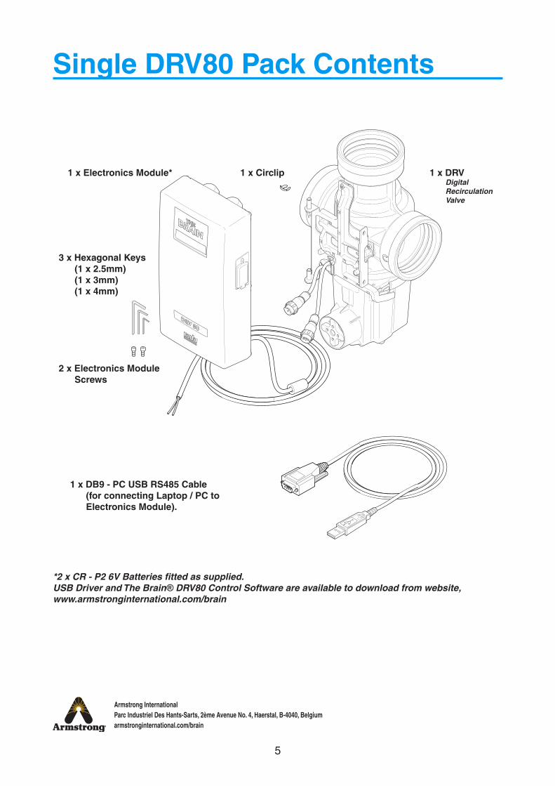
Single DRV80 Pack Contents
*2 x CR - P2 6V Batteries fitted as supplied.USB Driver and The Brain® DRV80 Control Software are available to download from website, www.armstronginternational.com/brain
2 x Electronics Module Screws
3 x Hexagonal Keys (1 x 2.5mm) (1 x 3mm) (1 x 4mm)
1 x Electronics Module* 1 x DRV Digital Recirculation Valve
1 x Circlip
1 x DB9 - PC USB RS485 Cable (for connecting Laptop / PC to Electronics Module).
6
Armstrong InternationalParc Industriel Des Hants-Sarts, 2ème Avenue No. 4, Haerstal, B-4040, Belgiumarmstronginternational.com/brain
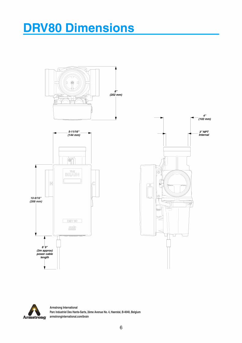
DRV80 Dimensions
8"(202 mm)
5-11/16"(144 mm)
6’ 9"(3m approx)power cable
length
10-9/16"(268 mm)
4"(102 mm)
3” NPTInternal

7
Armstrong InternationalParc Industriel Des Hants-Sarts, 2ème Avenue No. 4, Haerstal, B-4040, Belgiumarmstronginternational.com/brain
10-5/8"(270 mm)
2"(51 mm)
minimumrecommended
clearance
6-3/4"(172 mm)
1-3/16"(30 mm)

8
Armstrong InternationalParc Industriel Des Hants-Sarts, 2ème Avenue No. 4, Haerstal, B-4040, Belgiumarmstronginternational.com/brain
Technical Specifications
GeneralProtection NEMA 3S (IPx4)Ambient Temperature minimum ambient temperature of 2 °C maximum 50 °CAmbient Humidity 95% Non-condensingConnections 3” NPT Internal (female)Installation Environment Suitable for indoor use only
MaterialsElectronics Module: PC / ABSDRV: Stainless Steel, engineering plastics and elastomers
Safety Thermal shutdown upon inlet supply failure and / or power failureWeight DRV80 10.5 kg
Pressures
Maximum Inlet Supply PressureStatic Pressure 1034 kPa (10.3 bar)Dynamic Pressure 862 kPa (8.6 bar)
Supply Pressure Differential Inlet supply pressures must be nominally equal
TemperaturesMaximum Inlet Hot Water Supply 85°CMinimum Inlet Hot Water Supply 2°C above set pointMaximum Inlet Cold Water 25°CMinimum Inlet Cold Water 2°CSet Point Range 27 to 70°CMinimum Recirculation Loop Temperature Loss
1°C
Recirculation CircuitMinimum distance to First Outlet 7.6 m
Flow RatesMaximum Suggested Flow Rate 625 l/min at 2.3 m/sMinimum Recirculation Flow Rate 38 l/minMinimum System Draw-off 0 l/min during recirculation
ElectricalPower Supply 230V AC ~ 50HzSupply Fuse / Circuit Breaker Switched type 3 AmpBattery 2 x CR - P2 6VDuty Cycle Continuously rated
Auxiliary Relay (see Alerts - Activate Relay on Alert)Relay Type Single pole changeover relay contactsPower Supply 230V AC / 24V DCSupply Fuse 2 Amp
Specifications
Standards and CodesThe Brain® DRV80 conforms to the CE marking requirements.
2004/108/EC EMC Directive2006/95/EC Low Voltage Directive2011/65/EU RoHS Directive
EN 61326-1EN 61000-3-2EN 61000-3-3EN 61010-1EN 50581

9
Armstrong InternationalParc Industriel Des Hants-Sarts, 2ème Avenue No. 4, Haerstal, B-4040, Belgiumarmstronginternational.com/brain
Default SettingsDRV80 is preprogrammed to customer requirements prior to shipmentThe settings are derived from the Installation Detail Form (IDF) filled out by the customer when placing an order.
The Installation Detail Form (IDF) is available to download at www.armstronginternational.com/brain or consult factory
Armstrong Hot Water Group221 Armstrong Blvd
Three Rivers, MI 49093Phone: (269) 279-3602
Fax: (269) 279-3130
Digital Recirculating Valve (DRV) and Digital Mixing Center (DMC)Installation Details Form (IDF)
In order to enter P.O.'s and guarantee delivery dates, a technically accurate and complete IDF is required.
The review and acceptance of the information on the IDF by Armstrong:1. Approves the order for processing which triggers an e-mail confirmation2. Indicates that AHWG supports you by endorsing the application3. Initiates the warranty4. Delivers a complete, AHWG supported performance guarantee to the final user of the product5. Drives the relevant point of specification/influence, point of installation and point of order financial allocation if appropriate
Section 1 - Ordering Processing/Tracking Detail:
Point of Order (Sold To): (eg: ABC Mechanical)
City: State: Rep Firm:
Point of Installation: (eg: Heinz Ketchup)
City: State: Rep Firm:
Point of Specification: (eg: DEF Consulting Engineers)
Other Influence: (eg:Source of Recommendation)
Section 2 – Product Technical Detail:
1. DRV40 DRV50 DRV80
2. Inlet Hot Water Temp: °F
3. Inlet Hot Water Pressure: PSI
4. Inlet Cold Water Temp: °F
5. Inlet Cold Water Pressure: PSI
6. Maximum Simultaneous Demand: GPM
7. Recirculation Pump Flow: GPM
Section 3 – Digital Recirculation Valve (DRV) Option Detail:
1. DRV Outlet Water Temperature (OWT): °F
2. BS No Yes
Section 4 - Package Reference Information
Reference Drawing # Armstrong Model #
List Any Non-Standard Variations:
BSProtocol Options (Select One)
LonWorks
Modbus RTU
Modbus TCP
BACnet Metasys N2
BACnet MSTP
BACnet IP
Web Browser Interface
TCP/IP Configuration
DRV & DMC IDF Dec 2014
10
Armstrong InternationalParc Industriel Des Hants-Sarts, 2ème Avenue No. 4, Haerstal, B-4040, Belgiumarmstronginternational.com/brain
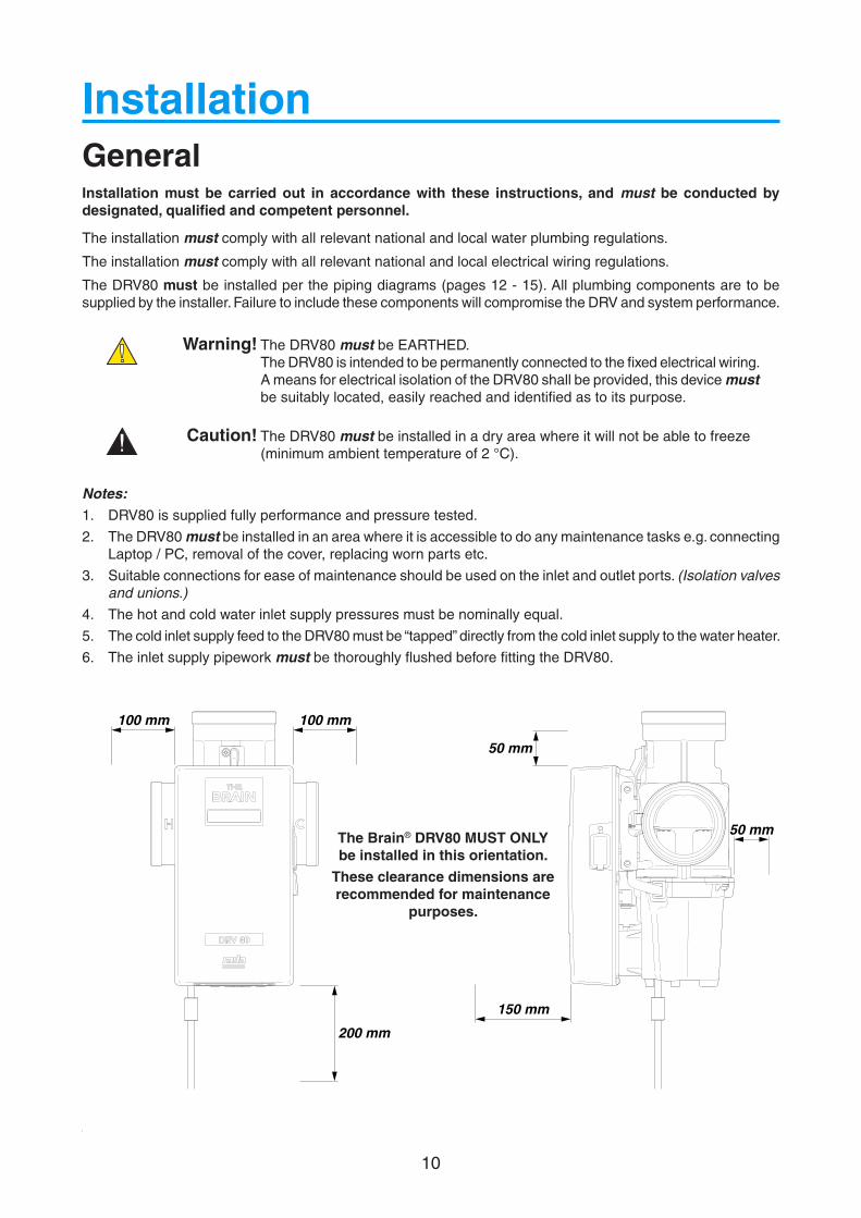
General
Installation
Notes:1. DRV80 is supplied fully performance and pressure tested.
2. The DRV80 must be installed in an area where it is accessible to do any maintenance tasks e.g. connecting Laptop / PC, removal of the cover, replacing worn parts etc.
3. Suitable connections for ease of maintenance should be used on the inlet and outlet ports. (Isolation valves and unions.)
4. The hot and cold water inlet supply pressures must be nominally equal.
5. The cold inlet supply feed to the DRV80 must be “tapped” directly from the cold inlet supply to the water heater.
6. The inlet supply pipework must be thoroughly flushed before fitting the DRV80.
200 mm
50 mm
100 mm 100 mm
150 mm
50 mmThe Brain® DRV80 MUST ONLY be installed in this orientation.
These clearance dimensions are recommended for maintenance
purposes.
Installation must be carried out in accordance with these instructions, and must be conducted by designated, qualified and competent personnel.
The installation must comply with all relevant national and local water plumbing regulations.
The installation must comply with all relevant national and local electrical wiring regulations.
The DRV80 must be installed per the piping diagrams (pages 12 - 15). All plumbing components are to be supplied by the installer. Failure to include these components will compromise the DRV and system performance.
Caution! The DRV80 must be installed in a dry area where it will not be able to freeze (minimum ambient temperature of 2 °C).
Warning! The DRV80 must be EARTHED.The DRV80 is intended to be permanently connected to the fixed electrical wiring. A means for electrical isolation of the DRV80 shall be provided, this device must be suitably located, easily reached and identified as to its purpose.
11
Armstrong InternationalParc Industriel Des Hants-Sarts, 2ème Avenue No. 4, Haerstal, B-4040, Belgiumarmstronginternational.com/brain
Installation RequirementsInlet isolating valves (full flow type) must be installed close to the DRV80 for ease of maintenance. It is recommended that outlet isolating valves (full flow type) are also installed.
The use of supply / return strainers will reduce debris entering the DRV80. The recommended gauge for such strainers is 35 mesh (mesh aperture dimension 0.5mm).
Inlet pressure tappings which allow measurement of the inlet pressures to the DRV80 under operating conditions are particularly recommended for in-service testing.
Pipework must be rigidly supported to avoid any strain on the connections.
Make sure the pipe layout will avoid the build up of trapped air in the system. Air release valves can be used where this is not possible.
Inlet and outlet threaded joint connections should be made with PTFE thread sealing tape or liquid sealant. Do not use oil-based, non-setting joint compounds.
To eliminate pipe debris it is essential that supply pipes are thoroughly flushed before connection to the DRV80.
1
2
3
4
5
6
7

12
Armstrong InternationalParc Industriel Des Hants-Sarts, 2ème Avenue No. 4, Haerstal, B-4040, Belgiumarmstronginternational.com/brain
H C
Isolation Valve
Sink
Shower
Thermometer
Strainer
Cold Water
Hot Water
Mixed Water
Check Valve
Recirculation Pump
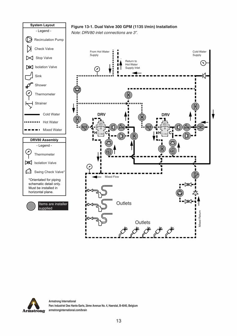
System Layout- Legend -
Stop Valve
DRV80 Assembly
Swing Check Valve*
- Legend -
Thermometer
Isolation Valve
*Orientated for pipingschematic detail only.Must be installed in horizontal plane.
Outlets
Return to Hot Water Supply Inlet
Cold Water Supply
Mix
ed R
etur
n
From Hot Water Supply
Outlets
DRV
Mixed Flow
Piping Diagrams
Items are installer supplied
Figure 12-1. Single Valve InstallationNote: For 0-90 GPM (0-340 l/min) Systems the DRV80 inlet connections are 2”
Note: For 0-150 GPM (0-567 l/min) Systems the DRV80 inlet connections are 3”
13
Armstrong InternationalParc Industriel Des Hants-Sarts, 2ème Avenue No. 4, Haerstal, B-4040, Belgiumarmstronginternational.com/brain
CH CH
Isolation Valve
Sink
Shower
Thermometer
Strainer
Cold Water
Hot Water
Mixed Water
Check Valve
Recirculation Pump
System Layout- Legend -
Stop Valve
DRV80 Assembly
Swing Check Valve*
- Legend -
Thermometer
Isolation Valve
*Orientated for pipingschematic detail only.Must be installed in horizontal plane.
Figure 13-1. Dual Valve 300 GPM (1135 l/min) InstallationNote: DRV80 inlet connections are 3”.
Outlets
OutletsM
ixed
Ret
urn
Cold Water Supply
Return to Hot Water Supply Inlet
From Hot Water Supply
Mixed Flow
DRV DRV
Items are installer supplied

14
Armstrong InternationalParc Industriel Des Hants-Sarts, 2ème Avenue No. 4, Haerstal, B-4040, Belgiumarmstronginternational.com/brain
Wafer Style Spring Check Valve
In-Line Check Valve
Isolation Valve
Sink
Shower
Thermometer
Strainer
Cold Water
Hot Water
Mixed Water
Check Valve
Recirculation Pump
System Layout- Legend -
Stop Valve
DRV80R Assembly- Legend -
Balancing Valve
Swing Check Valve*
Thermometer
Isolation Valve
*Orientated for pipingschematic detail only.Must be installed in horizontal plane.
H C
Figure 14-1. Single Valve InstallationNote: For 0-90 GPM (0-340 l/min) Systems the DRV80R inlet connections are 2”
Note: For 0-150 GPM (0-567 l/min) Systems the DRV80R inlet connections are 3”
DRV
Outlets
Outlets
Mix
ed R
etur
n
Cold Water Supply
Return to Hot Water Supply Inlet
From Hot Water Supply
Mixed Flow
Items are installer supplied

15
Armstrong InternationalParc Industriel Des Hants-Sarts, 2ème Avenue No. 4, Haerstal, B-4040, Belgiumarmstronginternational.com/brain
Isolation Valve
Sink
Shower
Thermometer
Strainer
Cold Water
Hot Water
Mixed Water
Check Valve
Recirculation Pump
System Layout- Legend -
Stop Valve
Balancing Valve
Wafer Style Spring Check Valve
In-Line Check Valve
DRV80R Assembly- Legend -
Swing Check Valve*
Thermometer
Isolation Valve
*Orientated for pipingschematic detail only.Must be installed in horizontal plane.
Outlets
OutletsM
ixed
Ret
urn
Cold Water Supply
Return to Hot Water Supply Inlet
From Hot Water Supply
Mixed Flow
DRV DRV
H C H C
Figure 15-1. Dual Valve 300 GPM (1135 l/min) InstallationNote: DRV80R inlet connections are 3”.
Items are installer supplied
16
Armstrong InternationalParc Industriel Des Hants-Sarts, 2ème Avenue No. 4, Haerstal, B-4040, Belgiumarmstronginternational.com/brain
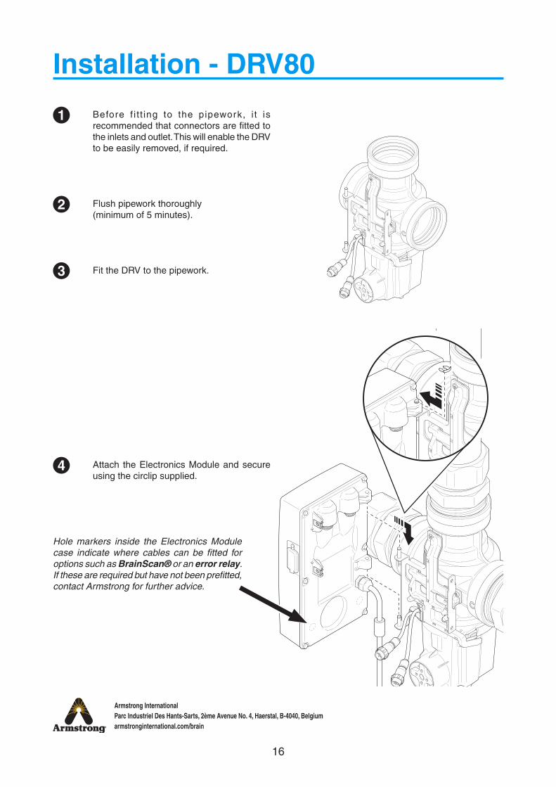
Installation - DRV80
Before f i t t ing to the pipework, i t is recommended that connectors are fitted to the inlets and outlet. This will enable the DRV to be easily removed, if required.
Flush pipework thoroughly (minimum of 5 minutes).
Fit the DRV to the pipework.
Attach the Electronics Module and secure using the circlip supplied.
1
2
3
4
Hole markers inside the Electronics Module case indicate where cables can be fitted for options such as BrainScan® or an error relay. If these are required but have not been prefitted, contact Armstrong for further advice.
17
Armstrong InternationalParc Industriel Des Hants-Sarts, 2ème Avenue No. 4, Haerstal, B-4040, Belgiumarmstronginternational.com/brain
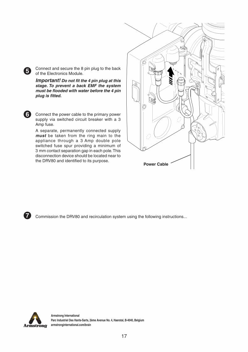
Connect and secure the 8 pin plug to the back of the Electronics Module.
Important! Do not fit the 4 pin plug at this stage. To prevent a back EMF the system must be flooded with water before the 4 pin plug is fitted.
Connect the power cable to the primary power supply via switched circuit breaker with a 3 Amp fuse.
A separate, permanently connected supply must be taken from the ring main to the appliance through a 3 Amp double pole switched fuse spur providing a minimum of 3 mm contact separation gap in each pole. This disconnection device should be located near to the DRV80 and identified to its purpose.
Commission the DRV80 and recirculation system using the following instructions...
6
7
5
Power Cable
18
Armstrong InternationalParc Industriel Des Hants-Sarts, 2ème Avenue No. 4, Haerstal, B-4040, Belgiumarmstronginternational.com/brain
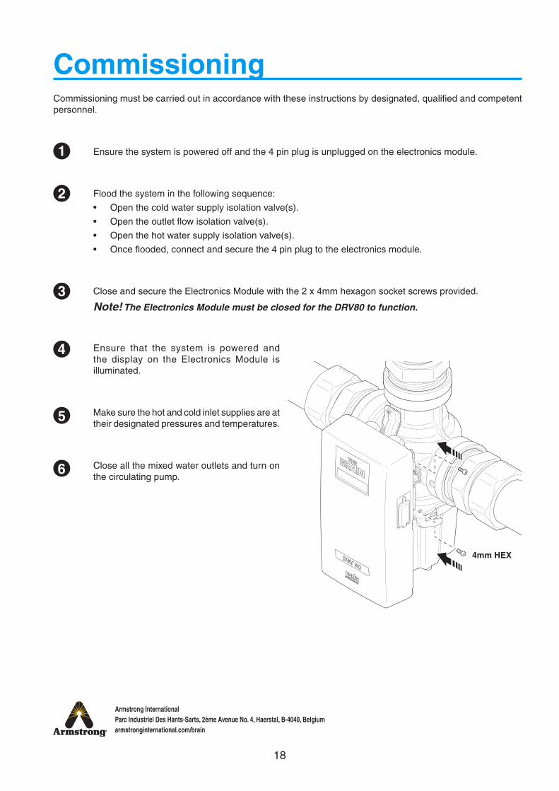
Ensure that the system is powered and the display on the Electronics Module is illuminated.
Make sure the hot and cold inlet supplies are at their designated pressures and temperatures.
Close all the mixed water outlets and turn on the circulating pump.
Ensure the system is powered off and the 4 pin plug is unplugged on the electronics module.
Flood the system in the following sequence:
• Open the cold water supply isolation valve(s).
• Open the outlet flow isolation valve(s).
• Open the hot water supply isolation valve(s).
• Once flooded, connect and secure the 4 pin plug to the electronics module.
Close and secure the Electronics Module with the 2 x 4mm hexagon socket screws provided.
Note! The Electronics Module must be closed for the DRV80 to function.
1
2
3
CommissioningCommissioning must be carried out in accordance with these instructions by designated, qualified and competent personnel.
4
4mm HEX
5
6
19
Armstrong InternationalParc Industriel Des Hants-Sarts, 2ème Avenue No. 4, Haerstal, B-4040, Belgiumarmstronginternational.com/brain
Temp. 48˚CSetpoint 49˚C
DRV80
Temp. 48˚CSetpoint 49˚C
Rada
Display as seen during normal operating mode
Current Outlet Temperature
Current Setpoint
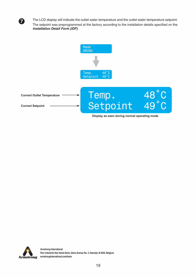
The LCD display will indicate the outlet water temperature and the outlet water temperature setpoint.
The setpoint was preprogrammed at the factory according to the installation details specified on the Installation Detail Form (IDF).
7
20
Armstrong InternationalParc Industriel Des Hants-Sarts, 2ème Avenue No. 4, Haerstal, B-4040, Belgiumarmstronginternational.com/brain
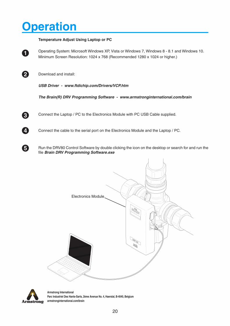
Temperature Adjust Using Laptop or PC
Operating System: Microsoft Windows XP, Vista or Windows 7, Windows 8 - 8.1 and Windows 10.
Minimum Screen Resolution: 1024 x 768 (Recommended 1280 x 1024 or higher.)
Download and install:
USB Driver - www.ftdichip.com/Drivers/VCP.htm
The Brain(R) DRV Programming Software - www.armstronginternational.com/brain
Connect the Laptop / PC to the Electronics Module with PC USB Cable supplied.
Connect the cable to the serial port on the Electronics Module and the Laptop / PC.
Run the DRV80 Control Software by double clicking the icon on the desktop or search for and run the file Brain DRV Programming Software.exe
Operation
1
2
3
4
5
Electronics Module
21
Armstrong InternationalParc Industriel Des Hants-Sarts, 2ème Avenue No. 4, Haerstal, B-4040, Belgiumarmstronginternational.com/brain
Control Software
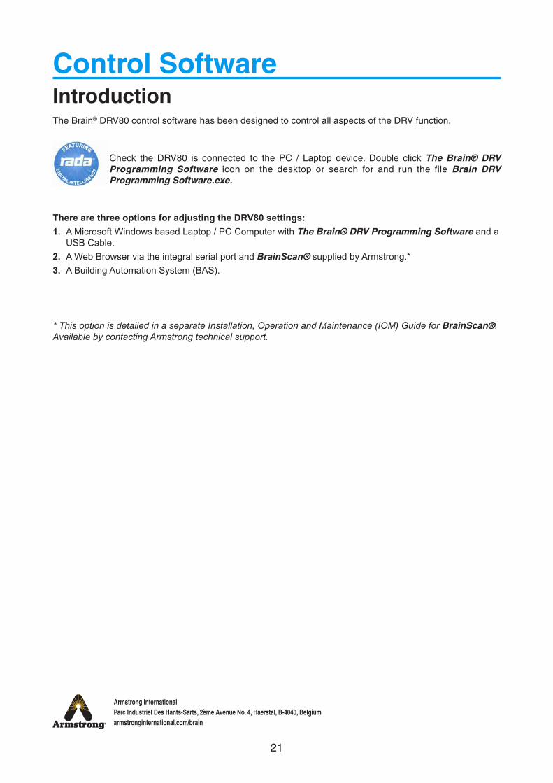
The Brain® DRV80 control software has been designed to control all aspects of the DRV function.
Check the DRV80 is connected to the PC / Laptop device. Double click The Brain® DRV Programming Software icon on the desktop or search for and run the file Brain DRV Programming Software.exe.
There are three options for adjusting the DRV80 settings:1. A Microsoft Windows based Laptop / PC Computer with The Brain® DRV Programming Software and a
USB Cable.2. A Web Browser via the integral serial port and BrainScan® supplied by Armstrong.*3. A Building Automation System (BAS).
* This option is detailed in a separate Installation, Operation and Maintenance (IOM) Guide for BrainScan®. Available by contacting Armstrong technical support.
Introduction
22
Armstrong InternationalParc Industriel Des Hants-Sarts, 2ème Avenue No. 4, Haerstal, B-4040, Belgiumarmstronginternational.com/brain
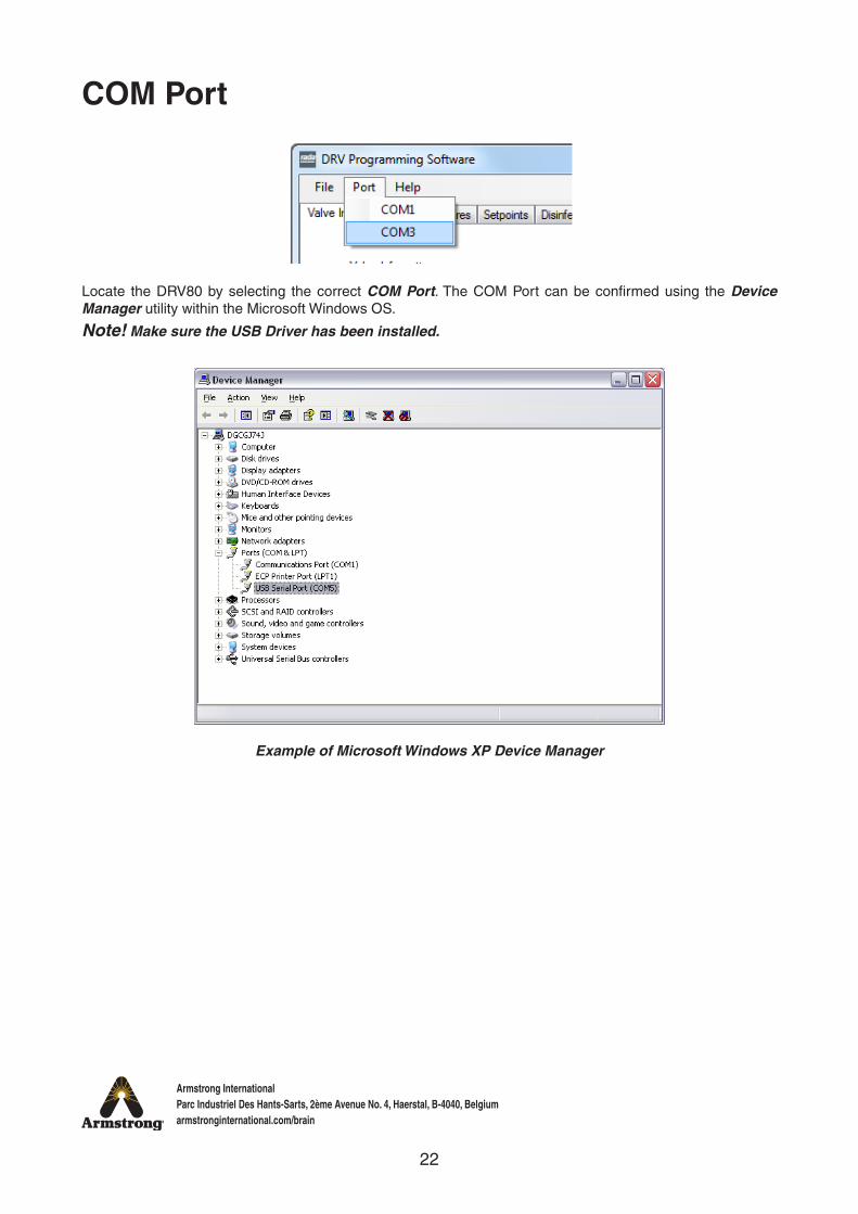
Locate the DRV80 by selecting the correct COM Port. The COM Port can be confirmed using the Device Manager utility within the Microsoft Windows OS.
Note! Make sure the USB Driver has been installed.
Example of Microsoft Windows XP Device Manager
COM Port
23
Armstrong InternationalParc Industriel Des Hants-Sarts, 2ème Avenue No. 4, Haerstal, B-4040, Belgiumarmstronginternational.com/brain
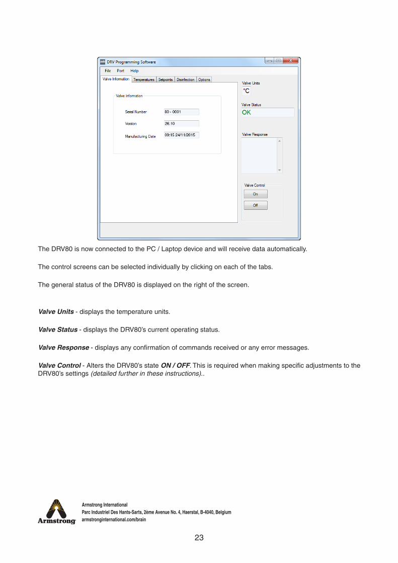
The DRV80 is now connected to the PC / Laptop device and will receive data automatically.
The control screens can be selected individually by clicking on each of the tabs.
The general status of the DRV80 is displayed on the right of the screen.
Valve Units - displays the temperature units.
Valve Status - displays the DRV80’s current operating status.
Valve Response - displays any confirmation of commands received or any error messages.
Valve Control - Alters the DRV80’s state ON / OFF. This is required when making specific adjustments to the DRV80’s settings (detailed further in these instructions)..
24
Armstrong InternationalParc Industriel Des Hants-Sarts, 2ème Avenue No. 4, Haerstal, B-4040, Belgiumarmstronginternational.com/brain
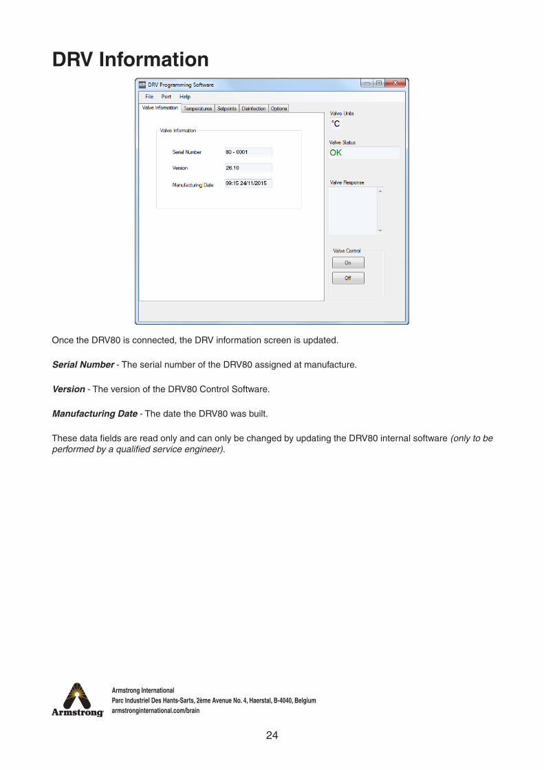
Once the DRV80 is connected, the DRV information screen is updated.
Serial Number - The serial number of the DRV80 assigned at manufacture.
Version - The version of the DRV80 Control Software.
Manufacturing Date - The date the DRV80 was built.
These data fields are read only and can only be changed by updating the DRV80 internal software (only to be performed by a qualified service engineer).
DRV Information
25
Armstrong InternationalParc Industriel Des Hants-Sarts, 2ème Avenue No. 4, Haerstal, B-4040, Belgiumarmstronginternational.com/brain
Temperatures
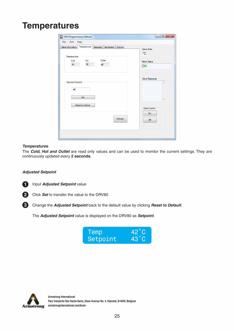
TemperaturesThe Cold, Hot and Outlet are read only values and can be used to monitor the current settings. They are continuously updated every 2 seconds.
Adjusted Setpoint
1
2
3
Input Adjusted Setpoint value
Click Set to transfer the value to the DRV80
Change the Adjusted Setpoint back to the default value by clicking Reset to Default.
The Adjusted Setpoint value is displayed on the DRV80 as Setpoint.
Temp 42˚CSetpoint 43˚C
26
Armstrong InternationalParc Industriel Des Hants-Sarts, 2ème Avenue No. 4, Haerstal, B-4040, Belgiumarmstronginternational.com/brain
Setpoints (Also see Setpoints - Explained page 28)
1
1
2
2
3
3
4
4
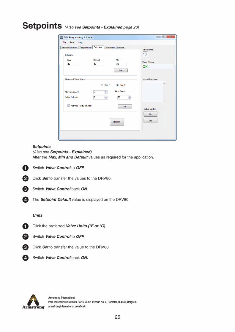
Setpoints (Also see Setpoints - Explained)Alter the Max, Min and Default values as required for the application.
Switch Valve Control to OFF.
Click Set to transfer the values to the DRV80.
Switch Valve Control back ON.
The Setpoint Default value is displayed on the DRV80.
Units
Click the preferred Valve Units (°F or °C).
Switch Valve Control to OFF.
Click Set to transfer the value to the DRV80.
Switch Valve Control back ON.
27
Armstrong InternationalParc Industriel Des Hants-Sarts, 2ème Avenue No. 4, Haerstal, B-4040, Belgiumarmstronginternational.com/brain
Alerts - optional(Also see Alerts - Explained page 29 and Preset Display Alerts page 31)
Input the Above Setpoint and Below Setpoint values.
Input the Error Temp value.
Click Activate Relay on Alerts if required.
Switch Valve Control to OFF.
Click Set to transfer the values to the DRV80.
Click Refresh to force display and confirm the updated values.
Switch Valve Control back ON.
5
6
7
1
2
3
4
28
Armstrong InternationalParc Industriel Des Hants-Sarts, 2ème Avenue No. 4, Haerstal, B-4040, Belgiumarmstronginternational.com/brain
Setpoints - Explained
Example 1
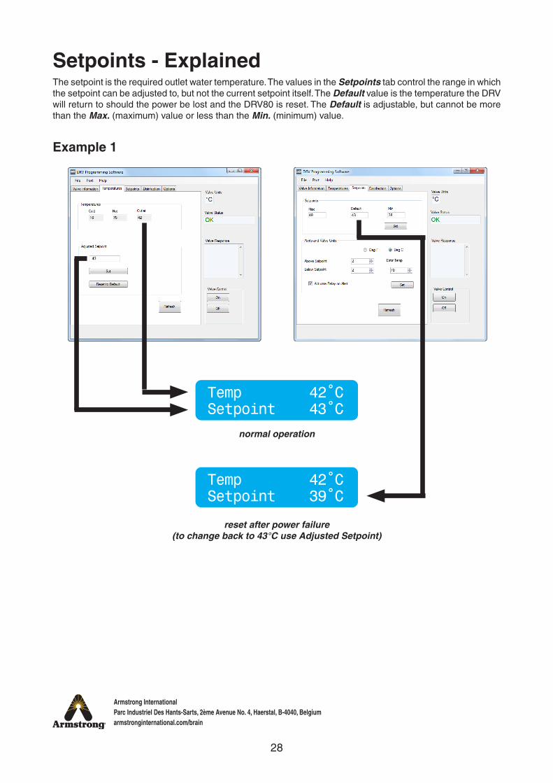
The setpoint is the required outlet water temperature. The values in the Setpoints tab control the range in which the setpoint can be adjusted to, but not the current setpoint itself. The Default value is the temperature the DRV will return to should the power be lost and the DRV80 is reset. The Default is adjustable, but cannot be more than the Max. (maximum) value or less than the Min. (minimum) value.
Temp 42˚CSetpoint 43˚C
Temp 42˚CSetpoint 39˚C
normal operation
reset after power failure (to change back to 43°C use Adjusted Setpoint)
29
Armstrong InternationalParc Industriel Des Hants-Sarts, 2ème Avenue No. 4, Haerstal, B-4040, Belgiumarmstronginternational.com/brain
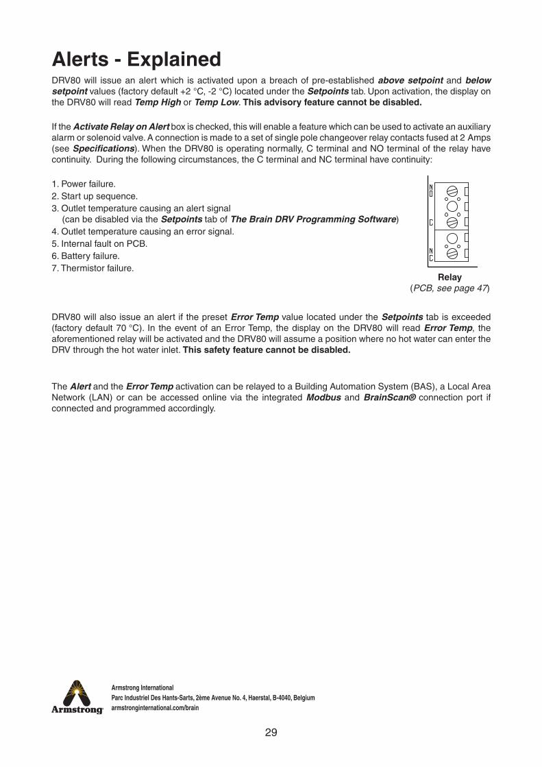
Alerts - ExplainedDRV80 will issue an alert which is activated upon a breach of pre-established above setpoint and below setpoint values (factory default +2 °C, -2 °C) located under the Setpoints tab. Upon activation, the display on the DRV80 will read Temp High or Temp Low. This advisory feature cannot be disabled.
If the Activate Relay on Alert box is checked, this will enable a feature which can be used to activate an auxiliary alarm or solenoid valve. A connection is made to a set of single pole changeover relay contacts fused at 2 Amps (see Specifications). When the DRV80 is operating normally, C terminal and NO terminal of the relay have continuity. During the following circumstances, the C terminal and NC terminal have continuity:
1. Power failure.2. Start up sequence.3. Outlet temperature causing an alert signal
(can be disabled via the Setpoints tab of The Brain DRV Programming Software)4. Outlet temperature causing an error signal.5. Internal fault on PCB.6. Battery failure.7. Thermistor failure.
DRV80 will also issue an alert if the preset Error Temp value located under the Setpoints tab is exceeded (factory default 70 °C). In the event of an Error Temp, the display on the DRV80 will read Error Temp, the aforementioned relay will be activated and the DRV80 will assume a position where no hot water can enter the DRV through the hot water inlet. This safety feature cannot be disabled.
The Alert and the Error Temp activation can be relayed to a Building Automation System (BAS), a Local Area Network (LAN) or can be accessed online via the integrated Modbus and BrainScan® connection port if connected and programmed accordingly.
Relay (PCB, see page 47)
30
Armstrong InternationalParc Industriel Des Hants-Sarts, 2ème Avenue No. 4, Haerstal, B-4040, Belgiumarmstronginternational.com/brain
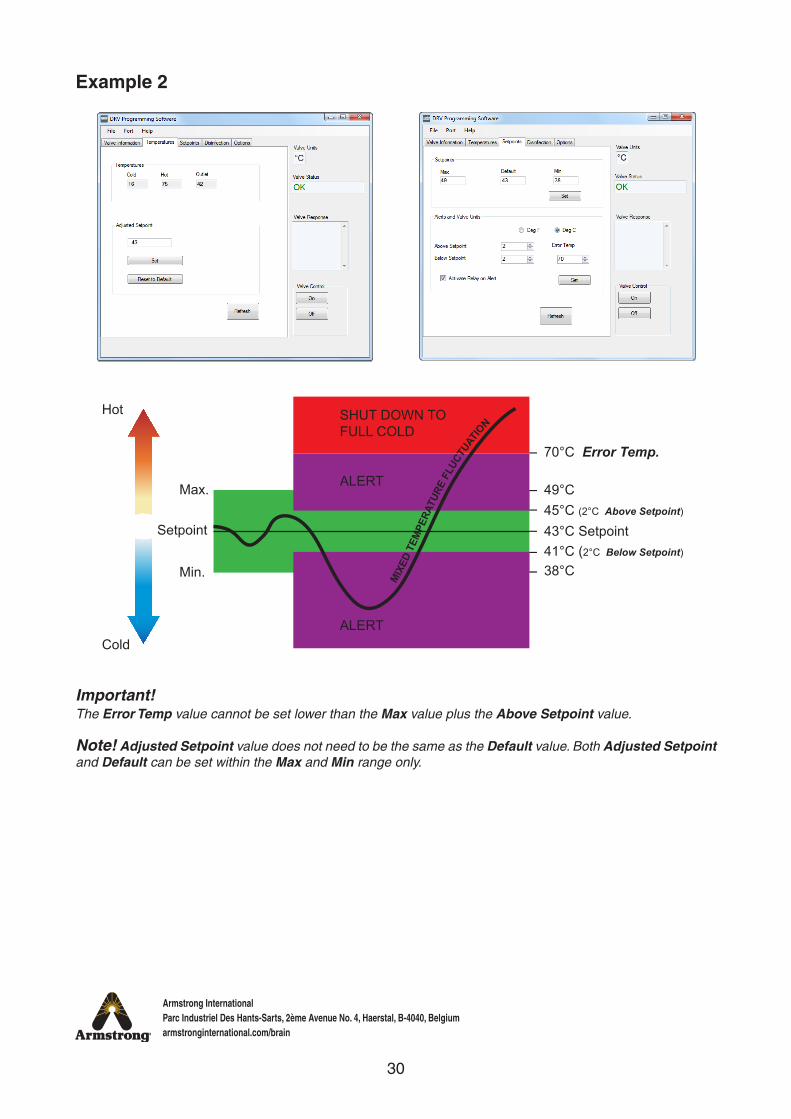
Important!The Error Temp value cannot be set lower than the Max value plus the Above Setpoint value.
Note! Adjusted Setpoint value does not need to be the same as the Default value. Both Adjusted Setpoint and Default can be set within the Max and Min range only.
MIX
ED T
EMPE
RATU
RE F
LUCT
UATIO
NMax.
Hot
Cold
ALERT
ALERT
SHUT DOWN TO FULL COLD
45°C (2°C Above Setpoint)
41°C (2°C Below Setpoint)
38°C
49°C
70°C Error Temp.
Min.
Setpoint 43°C Setpoint
Example 2
31
Armstrong InternationalParc Industriel Des Hants-Sarts, 2ème Avenue No. 4, Haerstal, B-4040, Belgiumarmstronginternational.com/brain
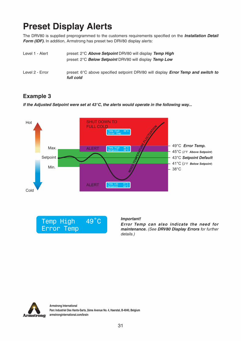
Preset Display AlertsThe DRV80 is supplied preprogrammed to the customers requirements specified on the Installation Detail Form (IDF). In addition, Armstrong has preset two DRV80 display alerts:
Level 1 - Alert preset: 2°C Above Setpoint DRV80 will display Temp High preset: 2°C Below Setpoint DRV80 will display Temp Low
Level 2 - Error preset: 6°C above specified setpoint DRV80 will display Error Temp and switch to full cold
Max.
Hot
Cold
ALERT
ALERT
SHUT DOWN TOFULL COLD
45°C (2°F Above Setpoint)
41°C (2°F Below Setpoint)
38°C
49°C Error Temp.
Min.
Setpoint 43°C Setpoint Default
MIX
ED T
EMPE
RATU
RE F
LUCT
UATIO
N
Temp Low 41˚CSetpoint 43˚C
Temp High 45˚CSetpoint 43˚C
Temp High 49˚CError Temp
Example 3If the Adjusted Setpoint were set at 43°C, the alerts would operate in the following way...
Temp High 49˚CError Temp
Important!Error Temp can also indicate the need for maintenance. (See DRV80 Display Errors for further details.)
32
Armstrong InternationalParc Industriel Des Hants-Sarts, 2ème Avenue No. 4, Haerstal, B-4040, Belgiumarmstronginternational.com/brain
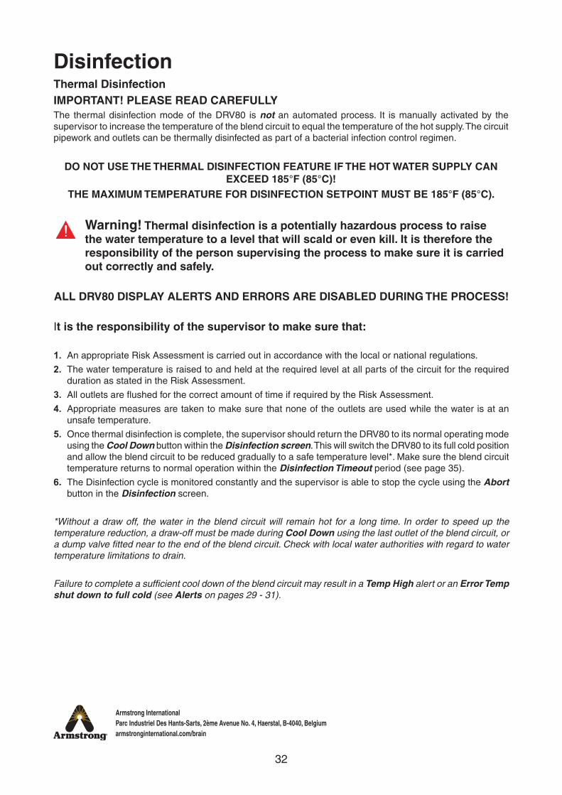
It is the responsibility of the supervisor to make sure that:
1. An appropriate Risk Assessment is carried out in accordance with the local or national regulations.
2. The water temperature is raised to and held at the required level at all parts of the circuit for the required duration as stated in the Risk Assessment.
3. All outlets are flushed for the correct amount of time if required by the Risk Assessment.
4. Appropriate measures are taken to make sure that none of the outlets are used while the water is at an unsafe temperature.
5. Once thermal disinfection is complete, the supervisor should return the DRV80 to its normal operating mode using the Cool Down button within the Disinfection screen. This will switch the DRV80 to its full cold position and allow the blend circuit to be reduced gradually to a safe temperature level*. Make sure the blend circuit temperature returns to normal operation within the Disinfection Timeout period (see page 35).
6. The Disinfection cycle is monitored constantly and the supervisor is able to stop the cycle using the Abort button in the Disinfection screen.
*Without a draw off, the water in the blend circuit will remain hot for a long time. In order to speed up the temperature reduction, a draw-off must be made during Cool Down using the last outlet of the blend circuit, or a dump valve fitted near to the end of the blend circuit. Check with local water authorities with regard to water temperature limitations to drain.
Failure to complete a sufficient cool down of the blend circuit may result in a Temp High alert or an Error Temp shut down to full cold (see Alerts on pages 29 - 31).
DisinfectionThermal DisinfectionIMPORTANT! PLEASE READ CAREFULLYThe thermal disinfection mode of the DRV80 is not an automated process. It is manually activated by the supervisor to increase the temperature of the blend circuit to equal the temperature of the hot supply. The circuit pipework and outlets can be thermally disinfected as part of a bacterial infection control regimen.
DO NOT USE THE THERMAL DISINFECTION FEATURE IF THE HOT WATER SUPPLY CAN EXCEED 185°F (85°C)!
THE MAXIMUM TEMPERATURE FOR DISINFECTION SETPOINT MUST BE 185°F (85°C).
Warning! Thermal disinfection is a potentially hazardous process to raise the water temperature to a level that will scald or even kill. It is therefore the responsibility of the person supervising the process to make sure it is carried out correctly and safely.
ALL DRV80 DISPLAY ALERTS AND ERRORS ARE DISABLED DURING THE PROCESS!
33
Armstrong InternationalParc Industriel Des Hants-Sarts, 2ème Avenue No. 4, Haerstal, B-4040, Belgiumarmstronginternational.com/brain
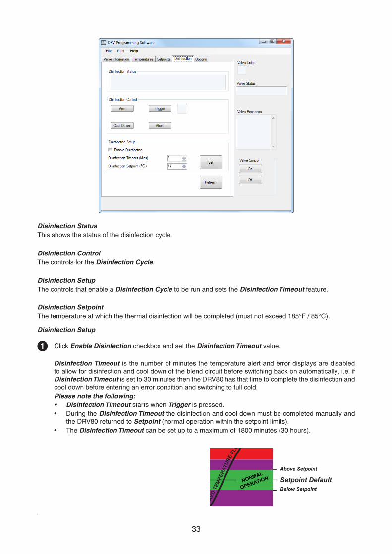
1 Click Enable Disinfection checkbox and set the Disinfection Timeout value.
Disinfection Timeout is the number of minutes the temperature alert and error displays are disabled to allow for disinfection and cool down of the blend circuit before switching back on automatically, i.e. if Disinfection Timeout is set to 30 minutes then the DRV80 has that time to complete the disinfection and cool down before entering an error condition and switching to full cold.Please note the following:• Disinfection Timeout starts when Trigger is pressed.• During the Disinfection Timeout the disinfection and cool down must be completed manually and
the DRV80 returned to Setpoint (normal operation within the setpoint limits).• The Disinfection Timeout can be set up to a maximum of 1800 minutes (30 hours).
Max.
Hot
Cold
ALERT
ALERT
SHUT DOWN TOFULL COLD
Above Setpoint
Below SetpointMin.
Setpoint Setpoint Default
MIX
ED T
EMPE
RATU
RE F
LUCT
UATIO
N
NORMAL
OPERATION
Disinfection StatusThis shows the status of the disinfection cycle.
Disinfection ControlThe controls for the Disinfection Cycle.
Disinfection SetupThe controls that enable a Disinfection Cycle to be run and sets the Disinfection Timeout feature.
Disinfection SetpointThe temperature at which the thermal disinfection will be completed (must not exceed 185°F / 85°C).
Disinfection Setup

34
Armstrong InternationalParc Industriel Des Hants-Sarts, 2ème Avenue No. 4, Haerstal, B-4040, Belgiumarmstronginternational.com/brain
2
3
4
Switch Valve Control to OFF.
Click Set to transfer the values to the DRV80.
Click Refresh to force display and confirm the updated values.
Disinfection Cycle
Warning!Due to the scalding temperature, the disinfection process must be supervised. The DRV80 should be monitored whilst in disinfection mode and no one should be allowed to approach within 3 meters of any affected outlets.
1 Click Arm when prepared for disinfection cycle, the Disinfection Status will confirm.
Within 20 seconds, click Trigger to activate the disinfection, the Disinfection Status will confirm.(There is a 10 second countdown before full hot is supplied to the blend circuit. The display on the DRV80 changes to confirm the disinfection cycle is active.)
2
Temp 77˚CDisinfection
35
Armstrong InternationalParc Industriel Des Hants-Sarts, 2ème Avenue No. 4, Haerstal, B-4040, Belgiumarmstronginternational.com/brain
3
4
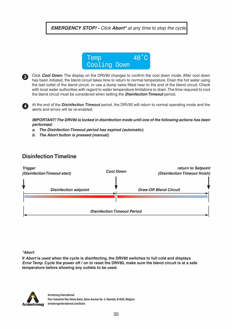
EMERGENCY STOP! - Click Abort* at any time to stop the cycle.
Click Cool Down. The display on the DRV80 changes to confirm the cool down mode. After cool down has been initiated, the blend circuit takes time to return to normal temperature. Drain the hot water using the last outlet of the blend circuit, or use a dump valve fitted near to the end of the blend circuit. Check with local water authorities with regard to water temperature limitations to drain. The time required to cool the blend circuit must be considered when setting the Disinfection Timeout period.
At the end of the Disinfection Timeout period, the DRV80 will return to normal operating mode and the alerts and errors will be re-enabled.
IMPORTANT! The DRV80 is locked in disinfection mode until one of the following actions has been performed:a. The Disinfection Timeout period has expired (automatic).b. The Abort button is pressed (manual).
Temp 48˚CCooling Down
Disinfection Timeline
Trigger(Disinfection Timeout start)
Disinfection setpoint
Disinfection Timeout Period
Draw-Off Blend Circuit
Cool Downreturn to Setpoint
(Disinfection Timeout finish)
*AbortIf Abort is used when the cycle is disinfecting, the DRV80 switches to full cold and displays Error Temp. Cycle the power off / on to reset the DRV80, make sure the blend circuit is at a safe temperature before allowing any outlets to be used.
36
Armstrong InternationalParc Industriel Des Hants-Sarts, 2ème Avenue No. 4, Haerstal, B-4040, Belgiumarmstronginternational.com/brain
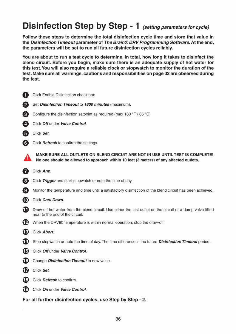
Disinfection Step by Step - 1 (setting parameters for cycle)
Follow these steps to determine the total disinfection cycle time and store that value in the Disinfection Timeout parameter of The Brain® DRV Programming Software. At the end, the parameters will be set to run all future disinfection cycles reliably.
You are about to run a test cycle to determine, in total, how long it takes to disinfect the blend circuit. Before you begin, make sure there is an adequate supply of hot water for this test. You will also require a reliable clock or stopwatch to monitor the duration of the test. Make sure all warnings, cautions and responsibilities on page 32 are observed during the test.
1 Click Enable Disinfection check box
2 Set Disinfection Timeout to 1800 minutes (maximum).
4 Click Off under Valve Control.
6 Click Refresh to confirm the settings.
For all further disinfection cycles, use Step by Step - 2.
7 Click Arm.
8 Click Trigger and start stopwatch or note the time of day.
9 Monitor the temperature and time until a satisfactory disinfection of the blend circuit has been achieved.
10 Click Cool Down.
11 Draw-off hot water from the blend circuit. Use either the last outlet on the circuit or a dump valve fitted near to the end of the circuit.
12 When the DRV80 temperature is within normal operation, stop the draw-off.
13 Click Abort.
14 Stop stopwatch or note the time of day. The time difference is the future Disinfection Timeout period.
15 Click Off under Valve Control.
16 Change Disinfection Timeout to new value.
17 Click Set.
Click Refresh to confirm.18
Click On under Valve Control.19
MAKE SURE ALL OUTLETS ON BLEND CIRCUIT ARE NOT IN USE UNTIL TEST IS COMPLETE!No one should be allowed to approach within 10 feet (3 meters) of any affected outlets.
3 Configure the disinfection setpoint as required (max 180 °F / 85 °C)
Click Set.5
37
Armstrong InternationalParc Industriel Des Hants-Sarts, 2ème Avenue No. 4, Haerstal, B-4040, Belgiumarmstronginternational.com/brain
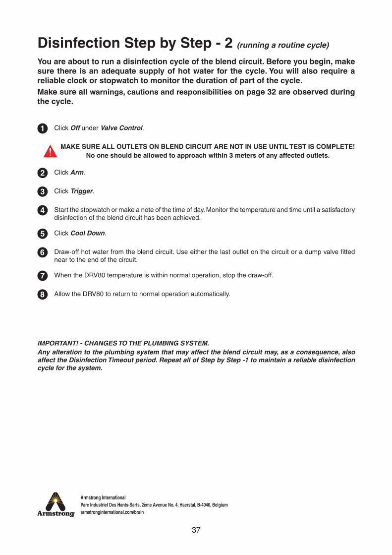
Disinfection Step by Step - 2 (running a routine cycle)
You are about to run a disinfection cycle of the blend circuit. Before you begin, make sure there is an adequate supply of hot water for the cycle. You will also require a reliable clock or stopwatch to monitor the duration of part of the cycle.Make sure all warnings, cautions and responsibilities on page 32 are observed during the cycle.
1
2
3
4
5
6
7
8
Click Off under Valve Control.
Click Arm.
Click Trigger.
Start the stopwatch or make a note of the time of day. Monitor the temperature and time until a satisfactory disinfection of the blend circuit has been achieved.
Click Cool Down.
Draw-off hot water from the blend circuit. Use either the last outlet on the circuit or a dump valve fitted near to the end of the circuit.
When the DRV80 temperature is within normal operation, stop the draw-off.
Allow the DRV80 to return to normal operation automatically.
IMPORTANT! - CHANGES TO THE PLUMBING SYSTEM.Any alteration to the plumbing system that may affect the blend circuit may, as a consequence, also affect the Disinfection Timeout period. Repeat all of Step by Step -1 to maintain a reliable disinfection cycle for the system.
MAKE SURE ALL OUTLETS ON BLEND CIRCUIT ARE NOT IN USE UNTIL TEST IS COMPLETE!No one should be allowed to approach within 3 meters of any affected outlets.
38
Armstrong InternationalParc Industriel Des Hants-Sarts, 2ème Avenue No. 4, Haerstal, B-4040, Belgiumarmstronginternational.com/brain
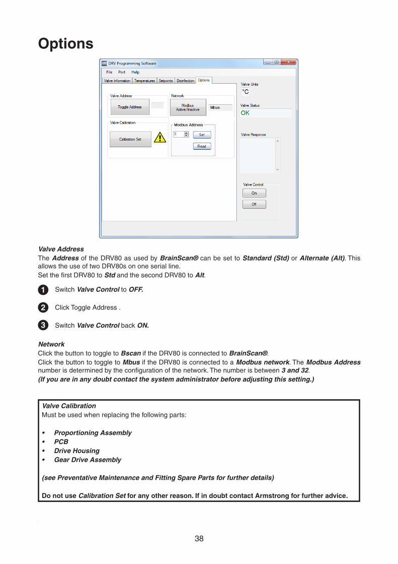
Options
Valve AddressThe Address of the DRV80 as used by BrainScan® can be set to Standard (Std) or Alternate (Alt). This allows the use of two DRV80s on one serial line.Set the first DRV80 to Std and the second DRV80 to Alt.
NetworkClick the button to toggle to Bscan if the DRV80 is connected to BrainScan®.Click the button to toggle to Mbus if the DRV80 is connected to a Modbus network. The Modbus Address number is determined by the configuration of the network. The number is between 3 and 32.(If you are in any doubt contact the system administrator before adjusting this setting.)
1
2
3
Switch Valve Control to OFF.
Click Toggle Address .
Switch Valve Control back ON.
Valve CalibrationMust be used when replacing the following parts:
• Proportioning Assembly• PCB• Drive Housing• Gear Drive Assembly
(see Preventative Maintenance and Fitting Spare Parts for further details)
Do not use Calibration Set for any other reason. If in doubt contact Armstrong for further advice.
39
Armstrong InternationalParc Industriel Des Hants-Sarts, 2ème Avenue No. 4, Haerstal, B-4040, Belgiumarmstronginternational.com/brain
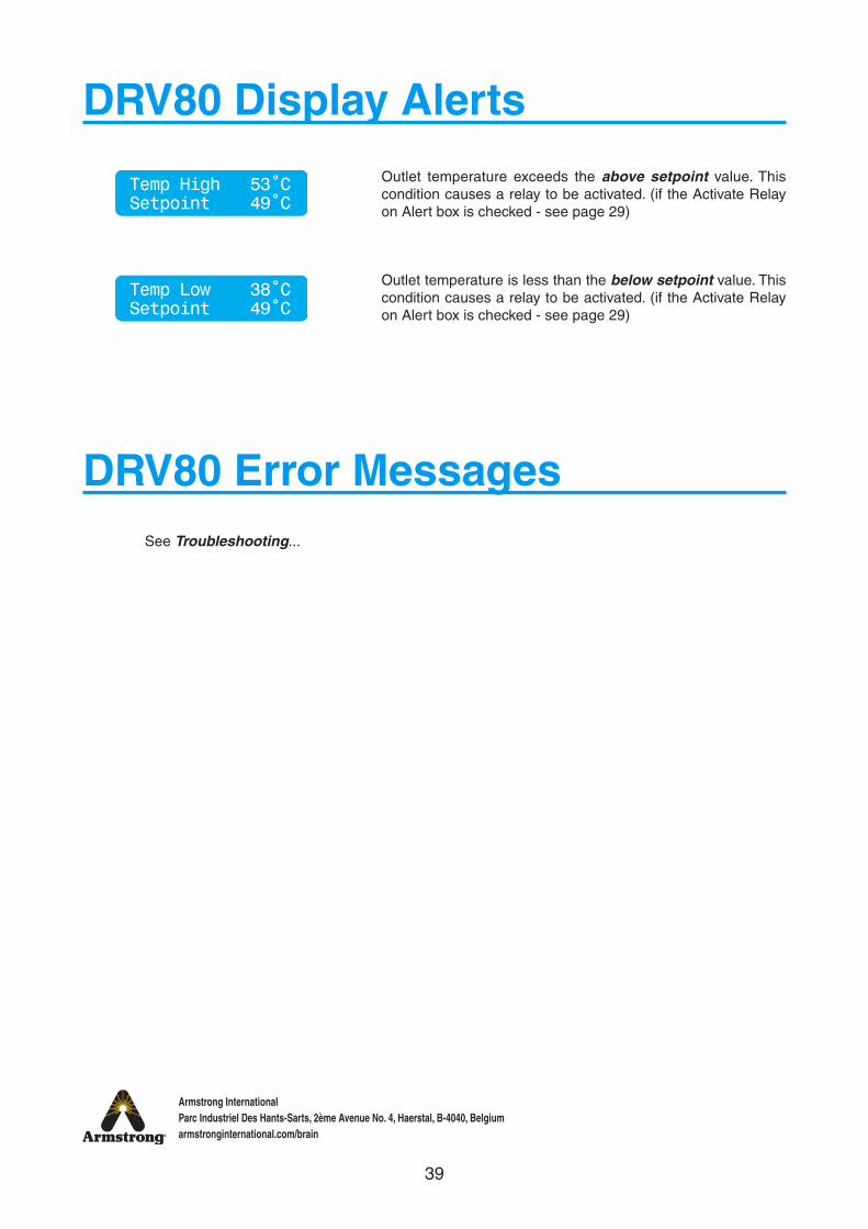
DRV80 Display Alerts
DRV80 Error MessagesSee Troubleshooting...
Temp High 53˚CSetpoint 49˚C
Temp Low 38˚CSetpoint 49˚C
Outlet temperature exceeds the above setpoint value. This condition causes a relay to be activated. (if the Activate Relay on Alert box is checked - see page 29)
Outlet temperature is less than the below setpoint value. This condition causes a relay to be activated. (if the Activate Relay on Alert box is checked - see page 29)
40
Armstrong InternationalParc Industriel Des Hants-Sarts, 2ème Avenue No. 4, Haerstal, B-4040, Belgiumarmstronginternational.com/brain
ConnectivityThe integral RS485 Serial Port (CN2 on the DRV80 PCB) can be used to connect to either BrainScan® or directly to Building Automation Systems (BAS) which operates on a Modbus RTU protocol.
See Options screen on page 38 for details on how to switch DRV80 for either BrainScan® or Modbus.
BrainScan® (not available in Europe)BrainScan® is an optionally selected control module from Armstrong which enables an interface with Building Automation Systems (BAS) which utilize Modbus, Bacnet™ or LonWorks™ protocols via the use of specific ProtoCessor cards.
BrainScan® also has an ethernet port and operates as a web server for remote network access.
BrainScan® includes remote hot water supply, cold / recirculation water supply, blended water outlet temperature outputs and is supplied with a system graphic, memory card for data storage and web based software.
BrainScan® includes terminals for additional installer supplied RTDs, pressure transducers and pulse type flow meters and this data can be forwarded via the BrainScan® interface.
A separate BrainScan® specific Installation, Operation and Maintenance (IOM) Guide is available upon request. Please consult factory or visit:www.armstronginternational.com/sites/default/files/resources/documents/IOM-690.pdf
ModbusModbus – DRV80 can be configured to communicate directly with BAS which utilize Modbus RTU.
When configured for Modbus the DRV80 becomes a Remote Terminal Unit (RTU).When connected directly to a BAS using Modbus RTU, the DRV80 will be assigned a unique network address which is programmed via the integral DB9 external port.
A separate Modbus specific Installation, Operation and Maintenance (IOM) Guide is available upon request. Please consult factory or visit:www.armstronginternational.com/sites/default/files/resources/documents/IOM-776.pdf

41
Armstrong InternationalParc Industriel Des Hants-Sarts, 2ème Avenue No. 4, Haerstal, B-4040, Belgiumarmstronginternational.com/brain
System PerformanceFor effective DRV80 performance, the DRV must be able to experience a minimum flow and a minimum temperature differential between its inlet and outlet supplies when the system is in zero demand.
Zero demand is defined as periods when there is no mixed water outlet usage on the system.
Pre-installation calculations should have already determined the system heat loss characteristics. For optimum performance the DRV80 requires a minimum of 1°C differential between the digital display on the unit (the outlet temperature) and the thermometer which is installed on the system return line.
When there is no system draw-off, the DRV80 reverts to a zero demand. The recirculation temperature is continuously monitored and adjusted appropriately by the DRV80. The circulating pump must operate continuously, the DRV80 requires a minimum flow of 38 l/m.
Pump CapacityThe circulating pump is only required to keep water gently moving around the system. The pump should be sized and selected to overcome the system resistance (feet of head) at the minimum specified flow rate of 38 l/m while also accounting for system heat loss.
System Safety MeasuresSystem safety measures such as the installation of an aquastat linked to the circulating pump which shuts the pump off if the system exceeds a given temperature setpoint is not required. DRV80 can be programmed to issue suitable alerts and / or system hot water shutoffs (DRV80) and shutdowns (Independent Solenoid Valve).

42
Armstrong InternationalParc Industriel Des Hants-Sarts, 2ème Avenue No. 4, Haerstal, B-4040, Belgiumarmstronginternational.com/brain
Preventative Maintenance and Fitting Spare Parts
Warning! Isolate power to the DRV80. Ensure that the circulating pump is not operating.
DRV80 components should be inspected annually, or more frequently where acknowledged site conditions such as high mineral content water dictate.
Each DRV80 has a serial number that is maintained on file with the technical department at Armstrong.
For any installation, operation, maintenance or technical support details not covered in this guide, please call our Technical Department quoting the model and / or serial number.
BatteriesBatteries are supplied to ensure the DRV switches to Full Cold in the event of a primary power supply failure, they should not be considered to be a backup power supply.
Battery life is variable depending upon usage. A battery error message appears on the DRV display when they require replacing.
Where primary power supply failure occurs regularly or the DRV is installed within a supply system where safety is critical, the batteries must be changed at least every 12 months as part of an annual maintenance routine.
In noncritical systems or where battery usage is low, longer replacement cycles may be considered up to a maximum of 5 years. Inspection of critical components and / or assemblies.
O - Rings / SealsAll ‘wetted’ O -Rings / Seals must be replaced at least every 12 months as part of an annual maintenance routine. In systems where water quality conditions are poor, more frequent replacement may be required.
StrainersAll supply strainers must be thoroughly cleaned at least every 12 months as part of an annual maintenance routine. Cleaning includes physically taking the strainer screen / basket out of the body and cleaning as well as flushing water through the body. In systems where water quality conditions are poor, more frequent cleaning may be required.
43
Armstrong InternationalParc Industriel Des Hants-Sarts, 2ème Avenue No. 4, Haerstal, B-4040, Belgiumarmstronginternational.com/brain
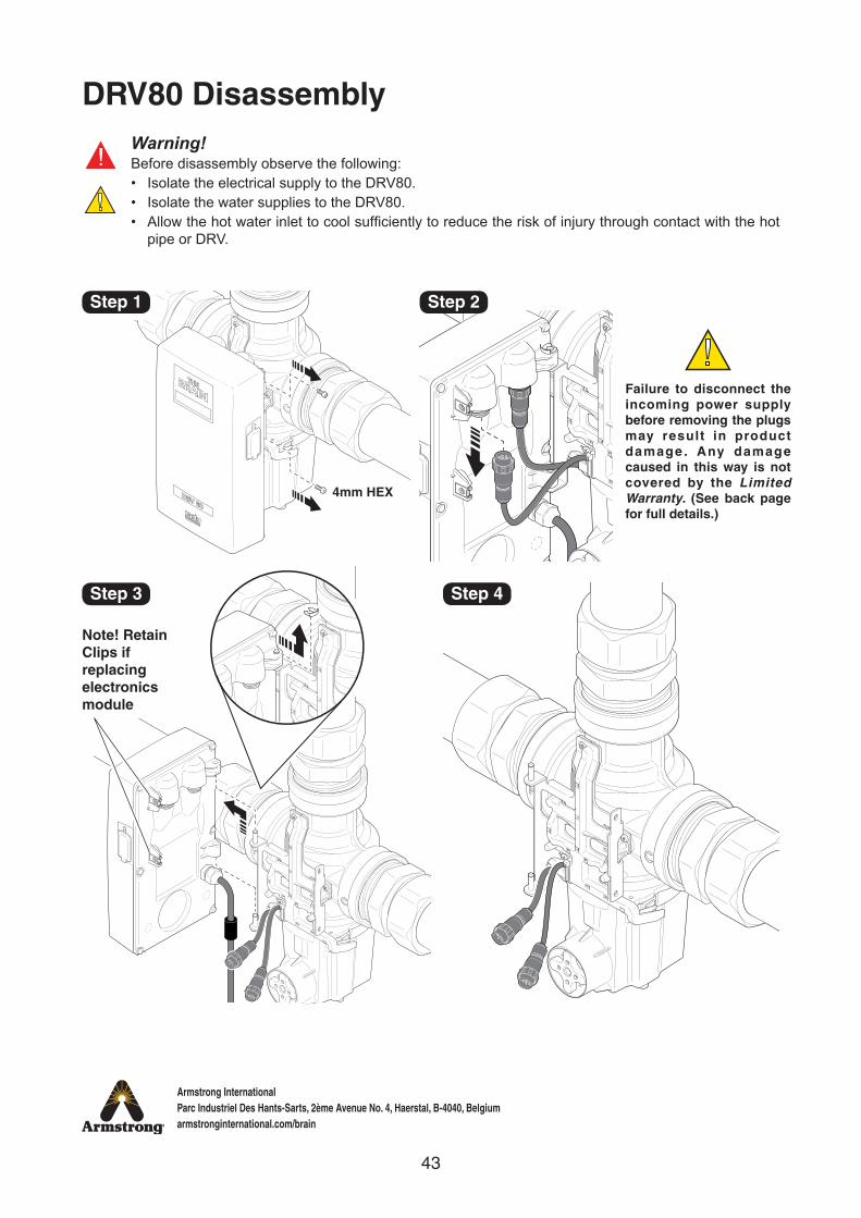
DRV80 DisassemblyWarning!Before disassembly observe the following:• Isolate the electrical supply to the DRV80.• Isolate the water supplies to the DRV80.• Allow the hot water inlet to cool sufficiently to reduce the risk of injury through contact with the hot
pipe or DRV.
4mm HEX
Step 1
Step 3 Step 4
Step 2
Failure to disconnect the incoming power supply before removing the plugs may result in product damage . Any damage caused in this way is not covered by the Limited Warranty. (See back page for full details.)
Note! Retain Clips if replacing electronics module
44
Armstrong InternationalParc Industriel Des Hants-Sarts, 2ème Avenue No. 4, Haerstal, B-4040, Belgiumarmstronginternational.com/brain
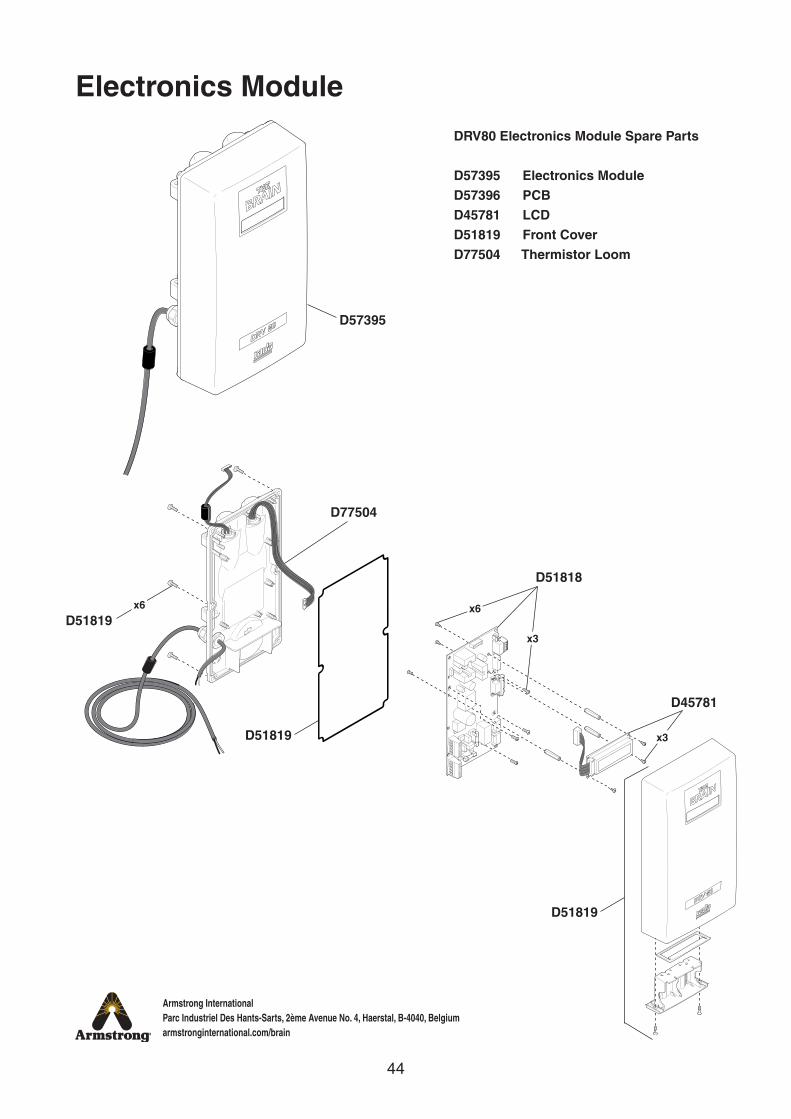
DRV80 Electronics Module Spare Parts
D57395 Electronics ModuleD57396 PCBD45781 LCDD51819 Front CoverD77504 Thermistor Loom
D57395
D51818
D45781
D51819
D51819
D51819
Electronics Module
x3
x3
x6x6
D77504
45
Armstrong InternationalParc Industriel Des Hants-Sarts, 2ème Avenue No. 4, Haerstal, B-4040, Belgiumarmstronginternational.com/brain
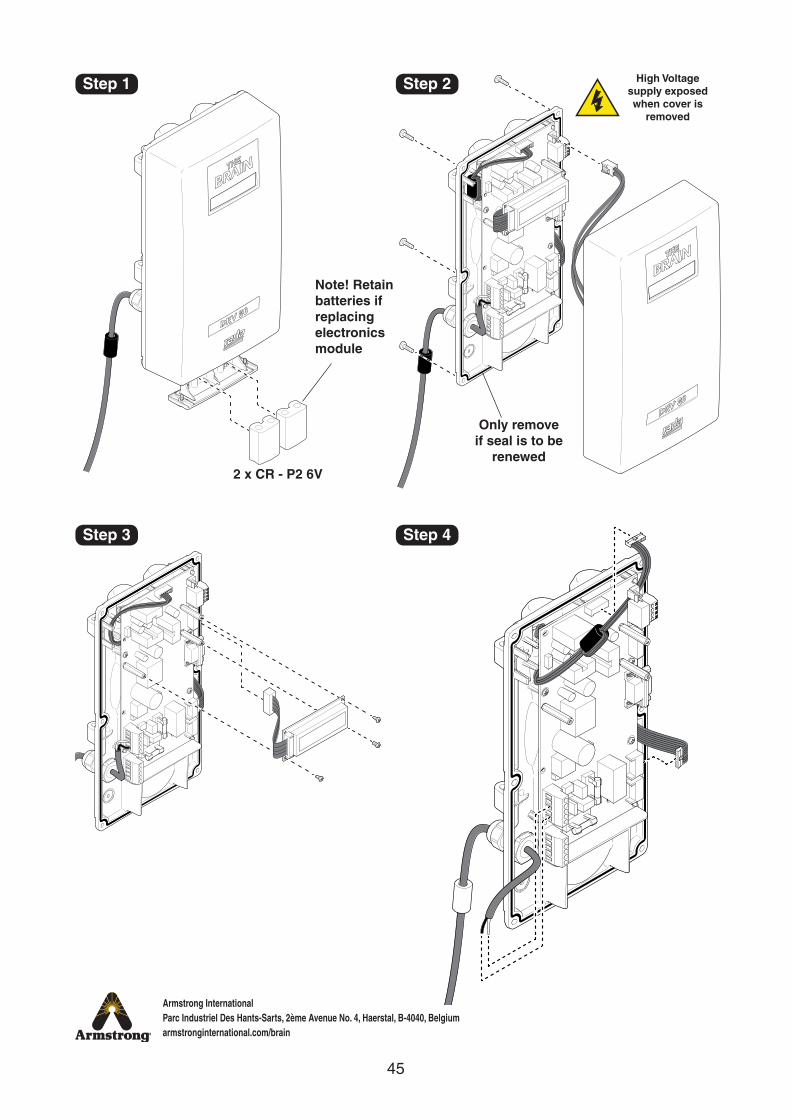
Step 1 Step 2
Step 3 Step 4
2 x CR - P2 6V
Only remove if seal is to be
renewed
High Voltage supply exposed when cover is
removed
Note! Retain batteries if replacing electronics module
46
Armstrong InternationalParc Industriel Des Hants-Sarts, 2ème Avenue No. 4, Haerstal, B-4040, Belgiumarmstronginternational.com/brain
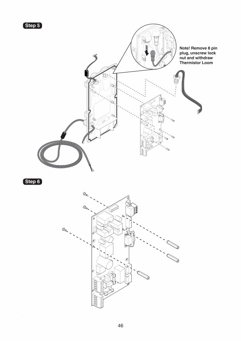
Step 5
Step 6
Note! Remove 8 pin plug, unscrew lock nut and withdraw Thermistor Loom
47
Armstrong InternationalParc Industriel Des Hants-Sarts, 2ème Avenue No. 4, Haerstal, B-4040, Belgiumarmstronginternational.com/brain
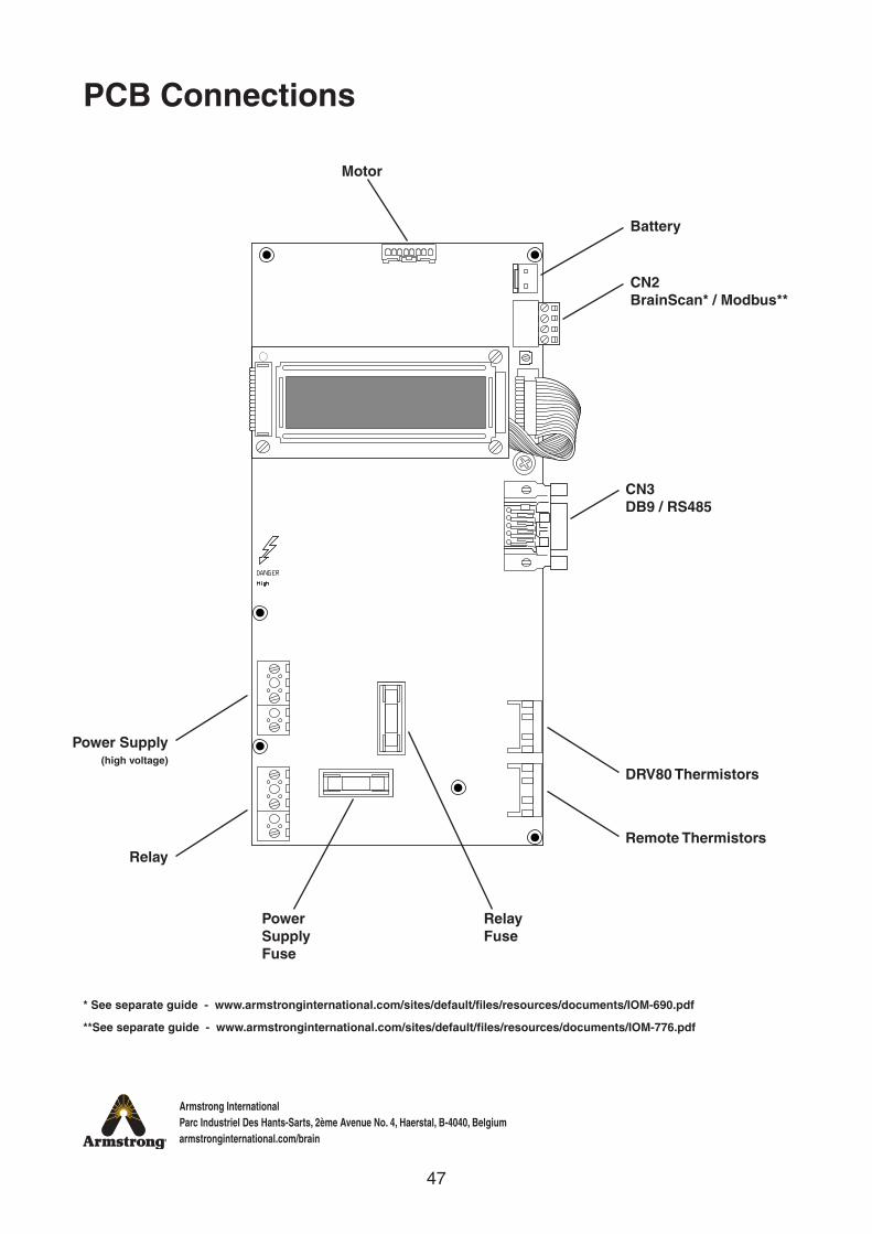
PCB Connections
Motor
Battery
CN3 DB9 / RS485
DRV80 Thermistors
Power Supply Fuse
Relay Fuse
Power Supply(high voltage)
RelayRemote Thermistors
CN2 BrainScan* / Modbus**
* See separate guide - www.armstronginternational.com/sites/default/files/resources/documents/IOM-690.pdf
**See separate guide - www.armstronginternational.com/sites/default/files/resources/documents/IOM-776.pdf

48
Armstrong InternationalParc Industriel Des Hants-Sarts, 2ème Avenue No. 4, Haerstal, B-4040, Belgiumarmstronginternational.com/brain
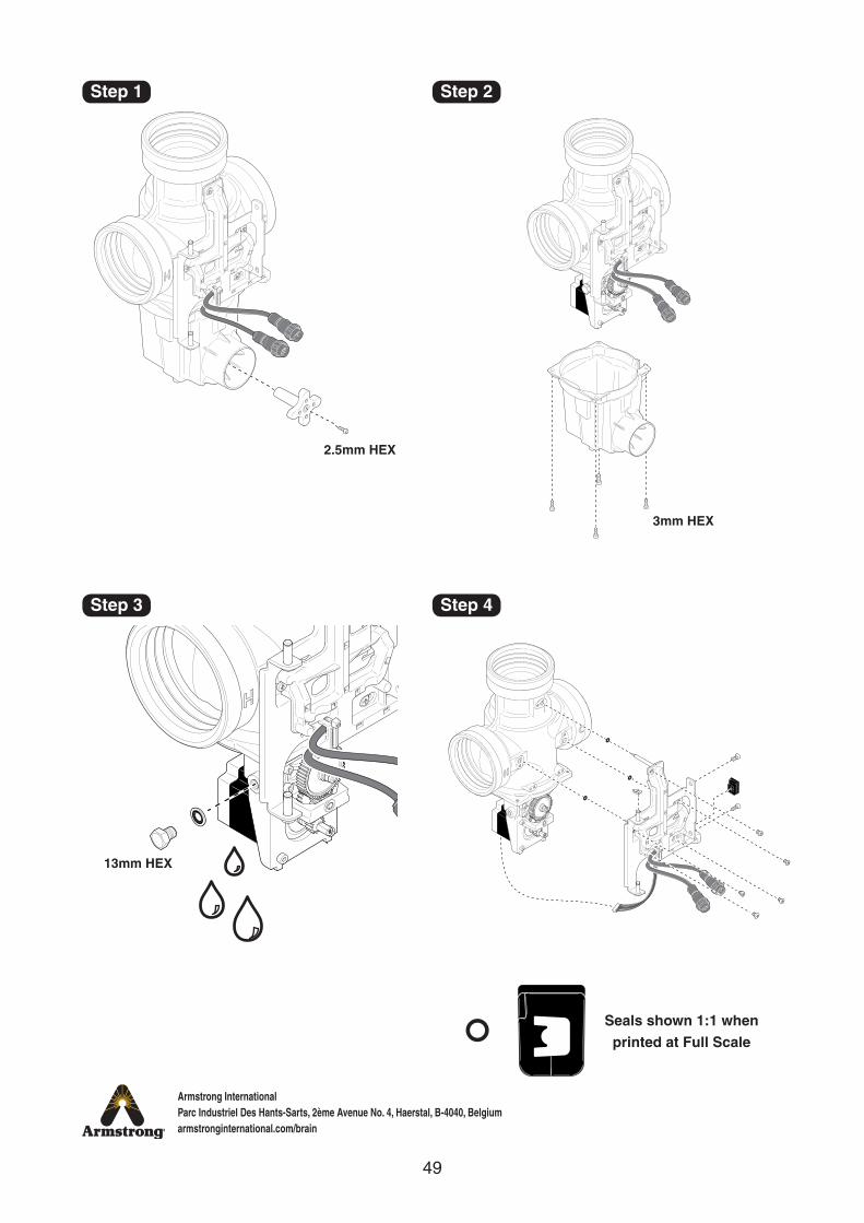
DRV80 DRV Spare Parts
D51820 Motor CoverD51821 Magnetic RotorD45786 Stepper MotorD51822 Cable Loom AssemblyD51823 Proportioning AssemblyD51824 Drive HousingD68927 Gear Drive AssemblyD45791 Drain PlugD51825 Seal PackD51826 Screw Pack
D51820
D51823
D51825
D51825
D45786
D45791D68927
D51824
D51825
D51822
D51826
D51826
D51826
D51825
D51822 D51825
D51821
x5
x3
DRV
x4
x4
x2
x5
x8
x12
49
Armstrong InternationalParc Industriel Des Hants-Sarts, 2ème Avenue No. 4, Haerstal, B-4040, Belgiumarmstronginternational.com/brain
2.5mm HEX
3mm HEX
13mm HEX
Step 1
Step 3 Step 4
Step 2
Seals shown 1:1 whenprinted at Full Scale
50
Armstrong InternationalParc Industriel Des Hants-Sarts, 2ème Avenue No. 4, Haerstal, B-4040, Belgiumarmstronginternational.com/brain
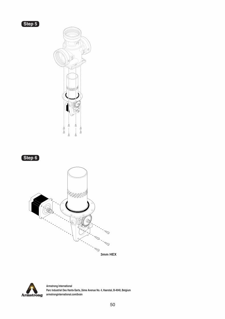
3mm HEX
Step 5
Step 6
51
Armstrong InternationalParc Industriel Des Hants-Sarts, 2ème Avenue No. 4, Haerstal, B-4040, Belgiumarmstronginternational.com/brain
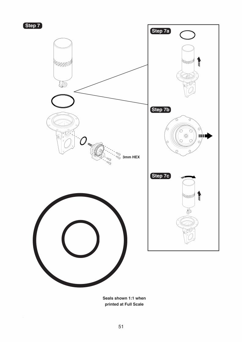
3mm HEX
Step 7Step 7a
Step 7c
Step 7b
Seals shown 1:1 whenprinted at Full Scale
52
Armstrong InternationalParc Industriel Des Hants-Sarts, 2ème Avenue No. 4, Haerstal, B-4040, Belgiumarmstronginternational.com/brain
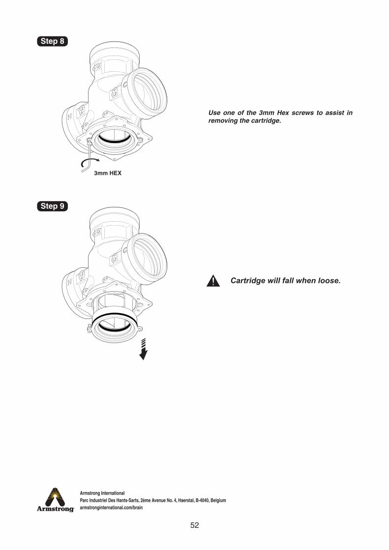
3mm HEX
Cartridge will fall when loose.
Use one of the 3mm Hex screws to assist in removing the cartridge.
Step 8
Step 9
53
Armstrong InternationalParc Industriel Des Hants-Sarts, 2ème Avenue No. 4, Haerstal, B-4040, Belgiumarmstronginternational.com/brain
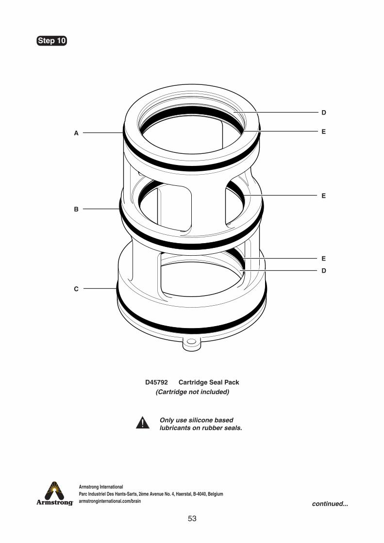
Only use silicone based lubricants on rubber seals.
A
D
E
E
E
D
B
C
D45792 Cartridge Seal Pack(Cartridge not included)
Step 10
continued...
54
Armstrong InternationalParc Industriel Des Hants-Sarts, 2ème Avenue No. 4, Haerstal, B-4040, Belgiumarmstronginternational.com/brain
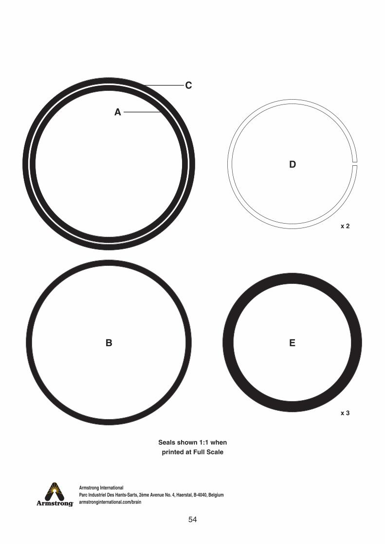
A
D
B E
C
x 2
x 3
Seals shown 1:1 whenprinted at Full Scale
55
Armstrong InternationalParc Industriel Des Hants-Sarts, 2ème Avenue No. 4, Haerstal, B-4040, Belgiumarmstronginternational.com/brain
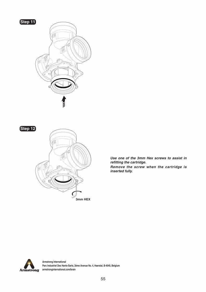
3mm HEX
Step 11
Step 12
Use one of the 3mm Hex screws to assist in refitting the cartridge.Remove the screw when the cartridge is inserted fully.
56
Armstrong InternationalParc Industriel Des Hants-Sarts, 2ème Avenue No. 4, Haerstal, B-4040, Belgiumarmstronginternational.com/brain
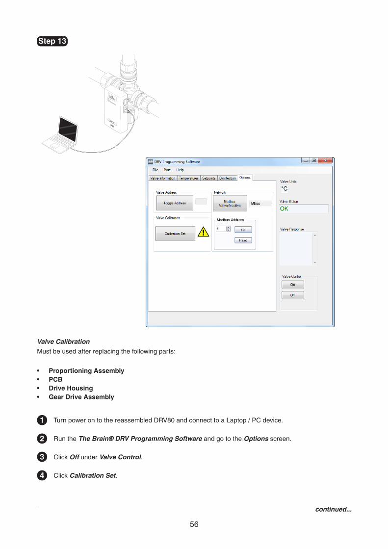
Step 13
Valve CalibrationMust be used after replacing the following parts:
• Proportioning Assembly• PCB• Drive Housing• Gear Drive Assembly
1
2
3
4
Turn power on to the reassembled DRV80 and connect to a Laptop / PC device.
Run the The Brain® DRV Programming Software and go to the Options screen.
Click Off under Valve Control.
Click Calibration Set.
continued...
57
Armstrong InternationalParc Industriel Des Hants-Sarts, 2ème Avenue No. 4, Haerstal, B-4040, Belgiumarmstronginternational.com/brain
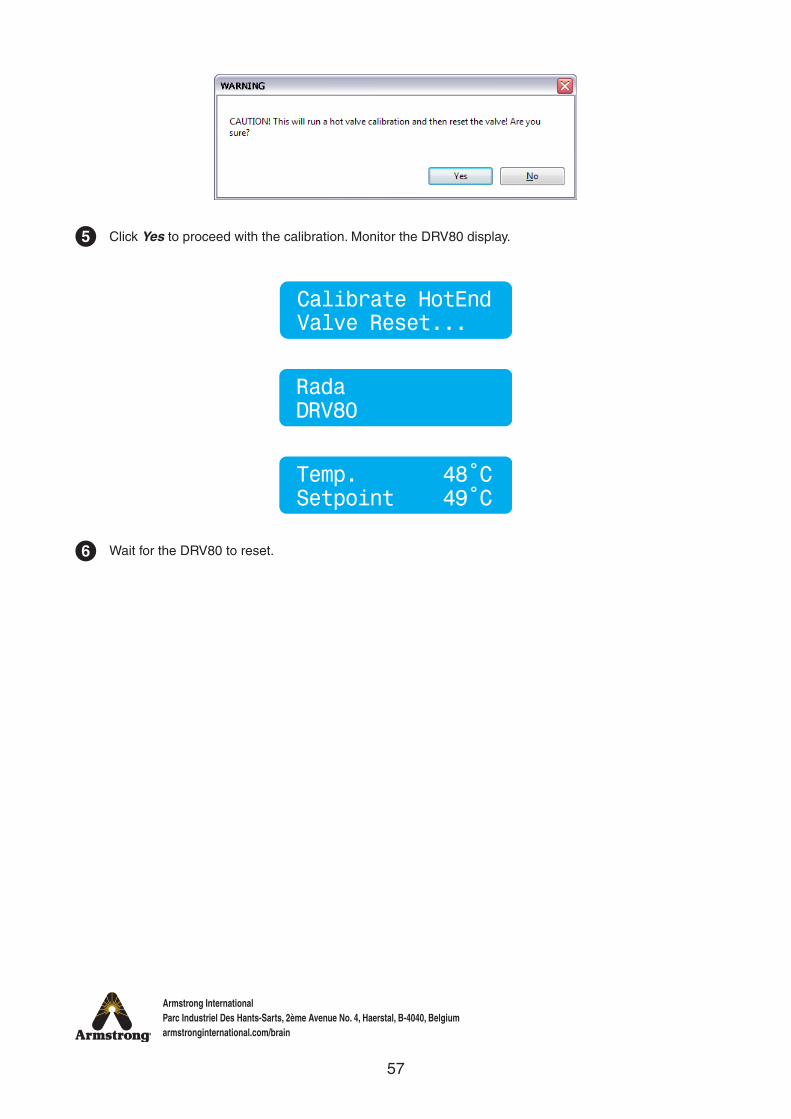
5 Click Yes to proceed with the calibration. Monitor the DRV80 display.
6
Calibrate HotEndValve Reset...
Temp. 48˚CSetpoint 49˚C
DRV80Rada
Wait for the DRV80 to reset.
58
Armstrong InternationalParc Industriel Des Hants-Sarts, 2ème Avenue No. 4, Haerstal, B-4040, Belgiumarmstronginternational.com/brain
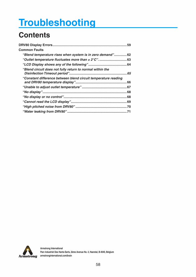
TroubleshootingContentsDRV80 Display Errors .................................................................................59Common Faults
“Blend temperature rises when system is in zero demand” ..............62“Outlet temperature fluctuates more than ± 2°C”. ..............................63“LCD Display shows any of the following” ..........................................64“Blend circuit does not fully return to normal within the
Disinfection Timeout period” ...............................................................65“Constant difference between blend circuit temperature reading
and DRV80 temperature display” ........................................................66“Unable to adjust outlet temperature” .................................................67“No display” ............................................................................................68“No display or no control” .....................................................................68“Cannot read the LCD display” .............................................................69“High pitched noise from DRV80” ........................................................70“Water leaking from DRV80” .................................................................71

59
Armstrong InternationalParc Industriel Des Hants-Sarts, 2ème Avenue No. 4, Haerstal, B-4040, Belgiumarmstronginternational.com/brain
DRV80 Display Errors
Emergency ModeSetpoint 49˚C
Temp 49˚CError PCB 0
Temp 49˚CError PCB 16
Temp 49˚CError PCB 32
Temp 49˚CError PCB 5
Indicates the PCB has failed, replace the PCB.
P/N - D57396 PCB, or
P/N - D57395 Electronics Module
see pages 43-46.
Maintenance to the DRV80 internal mechanism is required. DRV80 continues to operate safely, but with reduced performance. Check for the following:
• Motor damage or signs of wear
• Proportioning Assembly damage or signs of wear
• Debris in the Drive Housing
• Anything that could impair the movement of the Proportioning Assembly
If this mode is not addressed then it is likely the DRV80 will stop working and display any of the errors below.
Indicates the PCB has failed. Turn power off for 10 seconds and restart. If the error persists, replace the PCB.
P/N - D57396 PCB, or
P/N - D57395 Electronics Module
see pages 43-46.Temp 49˚CError Reset 37
Temp 49˚CError PCB
Temp 49˚CError Reset 90
Temp 49˚CError Reset 40
Temp 49˚CError Reset 8
Temp 49˚CError Reset 6+
+
+
+
+
60
Armstrong InternationalParc Industriel Des Hants-Sarts, 2ème Avenue No. 4, Haerstal, B-4040, Belgiumarmstronginternational.com/brain
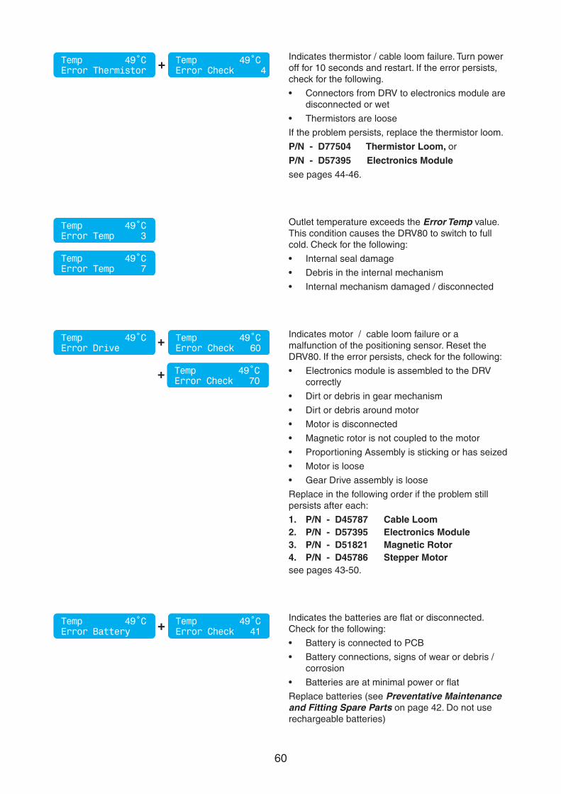
Temp 49˚CError Temp 3
Temp 49˚CError Temp 7
Outlet temperature exceeds the Error Temp value. This condition causes the DRV80 to switch to full cold. Check for the following:
• Internal seal damage
• Debris in the internal mechanism
• Internal mechanism damaged / disconnected
Indicates the batteries are flat or disconnected. Check for the following:
• Battery is connected to PCB
• Battery connections, signs of wear or debris / corrosion
• Batteries are at minimal power or flat
Replace batteries (see Preventative Maintenance and Fitting Spare Parts on page 42. Do not use rechargeable batteries)
Temp 49˚CError Battery
Temp 49˚CError Check 41+
Indicates motor / cable loom failure or a malfunction of the positioning sensor. Reset the DRV80. If the error persists, check for the following:
• Electronics module is assembled to the DRV correctly
• Dirt or debris in gear mechanism
• Dirt or debris around motor
• Motor is disconnected
• Magnetic rotor is not coupled to the motor
• Proportioning Assembly is sticking or has seized
• Motor is loose
• Gear Drive assembly is loose
Replace in the following order if the problem still persists after each:
1. P/N - D45787 Cable Loom2. P/N - D57395 Electronics Module3. P/N - D51821 Magnetic Rotor4. P/N - D45786 Stepper Motorsee pages 43-50.
Temp 49˚CError Drive
Temp 49˚CError Check 60
Temp 49˚CError Check 70
+
+
Temp 49˚CError Thermistor
Temp 49˚CError Check 4+
Indicates thermistor / cable loom failure. Turn power off for 10 seconds and restart. If the error persists, check for the following.
• Connectors from DRV to electronics module are disconnected or wet
• Thermistors are loose
If the problem persists, replace the thermistor loom.
P/N - D77504 Thermistor Loom, or
P/N - D57395 Electronics Modulesee pages 44-46.
61
Armstrong InternationalParc Industriel Des Hants-Sarts, 2ème Avenue No. 4, Haerstal, B-4040, Belgiumarmstronginternational.com/brain
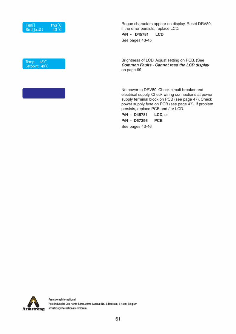
Temp 48˚CSetpoint 49˚C
Tem⌷ 1%$˚CSet⌷oi&t 43˚C
Rogue characters appear on display. Reset DRV80, if the error persists, replace LCD.
P/N - D45781 LCD See pages 43-45
Brightness of LCD. Adjust setting on PCB. (See Common Faults - Cannot read the LCD display on page 69.
No power to DRV80. Check circuit breaker and electrical supply. Check wiring connections at power supply terminal block on PCB (see page 47). Check power supply fuse on PCB (see page 47). If problem persists, replace PCB and / or LCD.
P/N - D45781 LCD, or
P/N - D57396 PCBSee pages 43-46
62
Armstrong InternationalParc Industriel Des Hants-Sarts, 2ème Avenue No. 4, Haerstal, B-4040, Belgiumarmstronginternational.com/brain
Common Faults
H C
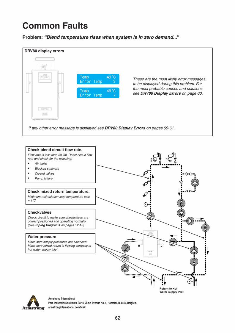
Problem: “Blend temperature rises when system is in zero demand...”
Check blend circuit flow rate.Flow rate is less than 38 l/m. Reset circuit flow rate and check for the following:
• Air locks
• Blocked strainers
• Closed valves
• Pump failure
Water pressureMake sure supply pressures are balanced. Make sure mixed return is flowing correctly to hot water supply inlet.
CheckvalvesCheck circuit to make sure checkvalves are correct positioned and operating normally. (See Piping Diagrams on pages 12-15)
Check mixed return temperature.Minimum recirculation loop temperature loss = 1°C
DRV80 display errors
These are the most likely error messages to be displayed during this problem. For the most probable causes and solutions see DRV80 Display Errors on page 60.
If any other error message is displayed see DRV80 Display Errors on pages 59-61.
Return to Hot Water Supply Inlet
Temp 49˚CError Temp 3
Temp 49˚CError Temp 7
63
Armstrong InternationalParc Industriel Des Hants-Sarts, 2ème Avenue No. 4, Haerstal, B-4040, Belgiumarmstronginternational.com/brain
H C
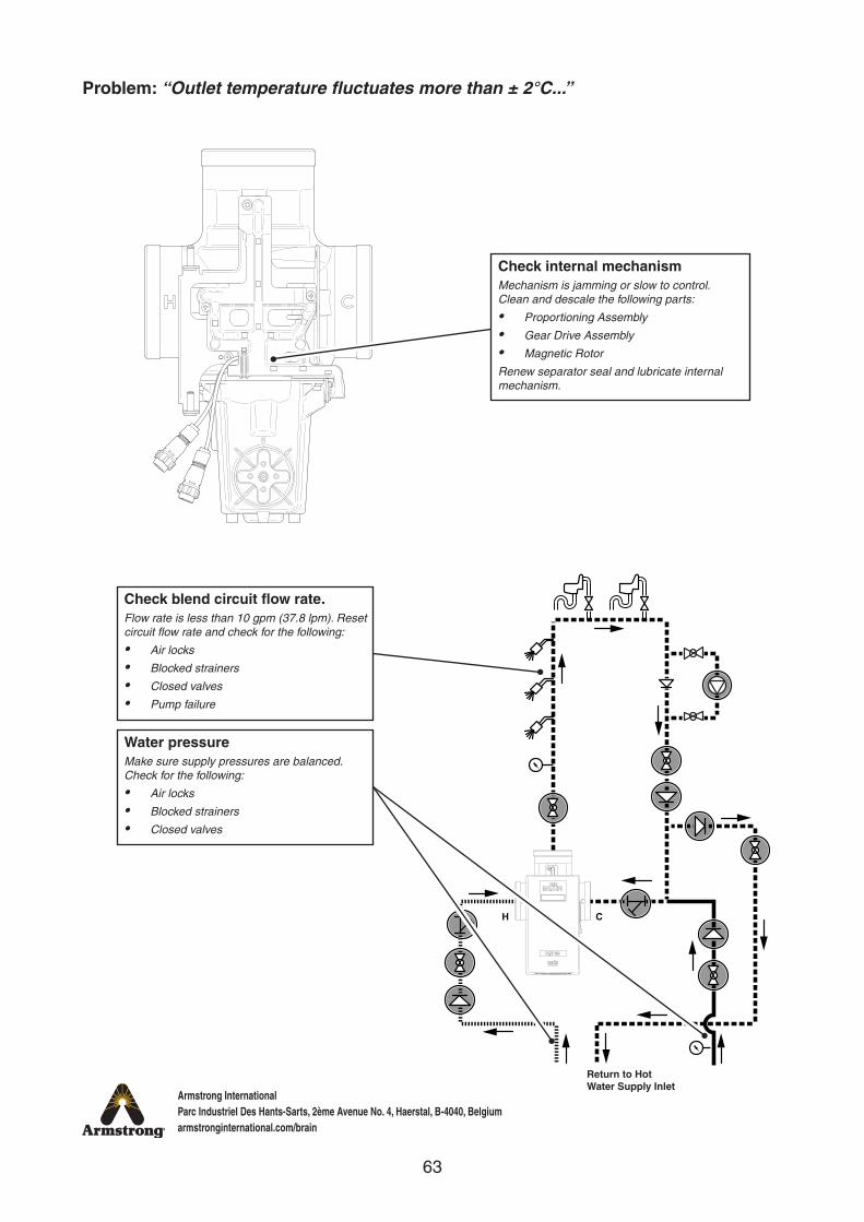
Problem: “Outlet temperature fluctuates more than ± 2°C...”
Check internal mechanismMechanism is jamming or slow to control. Clean and descale the following parts:
• Proportioning Assembly
• Gear Drive Assembly
• Magnetic Rotor
Renew separator seal and lubricate internal mechanism.
Water pressureMake sure supply pressures are balanced. Check for the following:
• Air locks
• Blocked strainers
• Closed valves
Return to Hot Water Supply Inlet
Check blend circuit flow rate.Flow rate is less than 10 gpm (37.8 lpm). Reset circuit flow rate and check for the following:
• Air locks
• Blocked strainers
• Closed valves
• Pump failure
64
Armstrong InternationalParc Industriel Des Hants-Sarts, 2ème Avenue No. 4, Haerstal, B-4040, Belgiumarmstronginternational.com/brain
H C
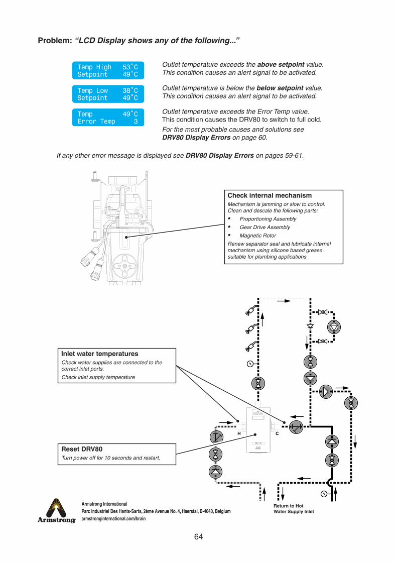
Problem: “LCD Display shows any of the following...”
Check internal mechanismMechanism is jamming or slow to control. Clean and descale the following parts:
• Proportioning Assembly
• Gear Drive Assembly
• Magnetic Rotor
Renew separator seal and lubricate internal mechanism using silicone based grease suitable for plumbing applications
Reset DRV80Turn power off for 10 seconds and restart.
Inlet water temperaturesCheck water supplies are connected to the correct inlet ports.
Check inlet supply temperature
If any other error message is displayed see DRV80 Display Errors on pages 59-61.
Return to Hot Water Supply Inlet
Outlet temperature exceeds the above setpoint value. This condition causes an alert signal to be activated.
Outlet temperature is below the below setpoint value. This condition causes an alert signal to be activated.
Outlet temperature exceeds the Error Temp value. This condition causes the DRV80 to switch to full cold.
For the most probable causes and solutions see DRV80 Display Errors on page 60.
Temp High 53˚CSetpoint 49˚C
Temp Low 38˚CSetpoint 49˚C
Temp 49˚CError Temp 3
65
Armstrong InternationalParc Industriel Des Hants-Sarts, 2ème Avenue No. 4, Haerstal, B-4040, Belgiumarmstronginternational.com/brain
H C
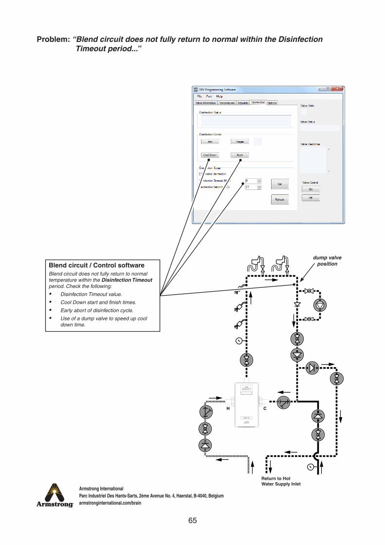
Problem: “Blend circuit does not fully return to normal within the Disinfection Timeout period...”
Blend circuit / Control softwareBlend circuit does not fully return to normal temperature within the Disinfection Timeout period. Check the following:
• Disinfection Timeout value.
• Cool Down start and finish times.
• Early abort of disinfection cycle.
• Use of a dump valve to speed up cool down time.
dump valve position
Return to Hot Water Supply Inlet

66
Armstrong InternationalParc Industriel Des Hants-Sarts, 2ème Avenue No. 4, Haerstal, B-4040, Belgiumarmstronginternational.com/brain
Problem: “Constant difference between blend circuit temperature reading and DRV80 temperature display...”
H C
Readings are not equal after outlet temperature has stabilized
H C
Check outlet thermistorTurn power off for 10 seconds and restart. If the error persists, check the thermistor connections or replace the thermistors.
Blend circuit thermometerCheck or replace.
67
Armstrong InternationalParc Industriel Des Hants-Sarts, 2ème Avenue No. 4, Haerstal, B-4040, Belgiumarmstronginternational.com/brain
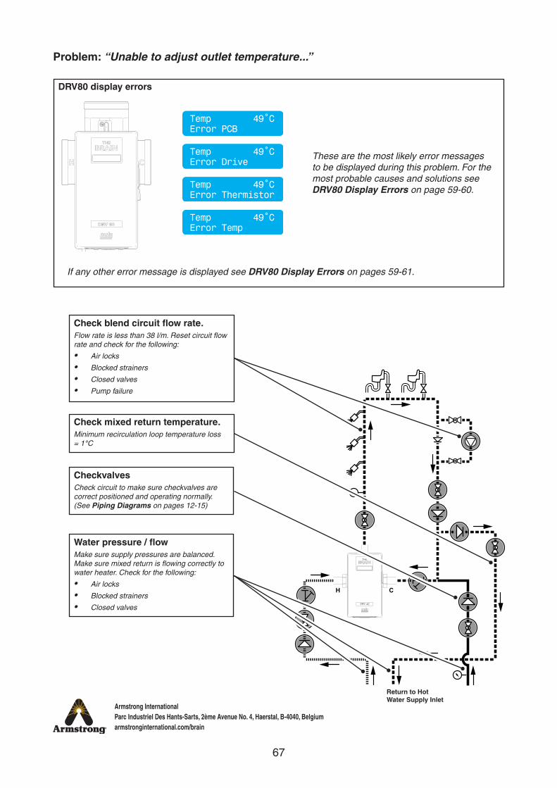
Problem: “Unable to adjust outlet temperature...”
H C
Water pressure / flowMake sure supply pressures are balanced. Make sure mixed return is flowing correctly to water heater. Check for the following:
• Air locks
• Blocked strainers
• Closed valves
CheckvalvesCheck circuit to make sure checkvalves are correct positioned and operating normally. (See Piping Diagrams on pages 12-15)
Check mixed return temperature.Minimum recirculation loop temperature loss = 1°C
Check blend circuit flow rate.Flow rate is less than 38 l/m. Reset circuit flow rate and check for the following:
• Air locks
• Blocked strainers
• Closed valves
• Pump failure
DRV80 display errors
If any other error message is displayed see DRV80 Display Errors on pages 59-61.
Return to Hot Water Supply Inlet
These are the most likely error messages to be displayed during this problem. For the most probable causes and solutions see DRV80 Display Errors on page 59-60.
Temp 49˚CError PCB
Temp 49˚CError Drive
Temp 49˚CError Temp
Temp 49˚CError Thermistor
68
Armstrong InternationalParc Industriel Des Hants-Sarts, 2ème Avenue No. 4, Haerstal, B-4040, Belgiumarmstronginternational.com/brain
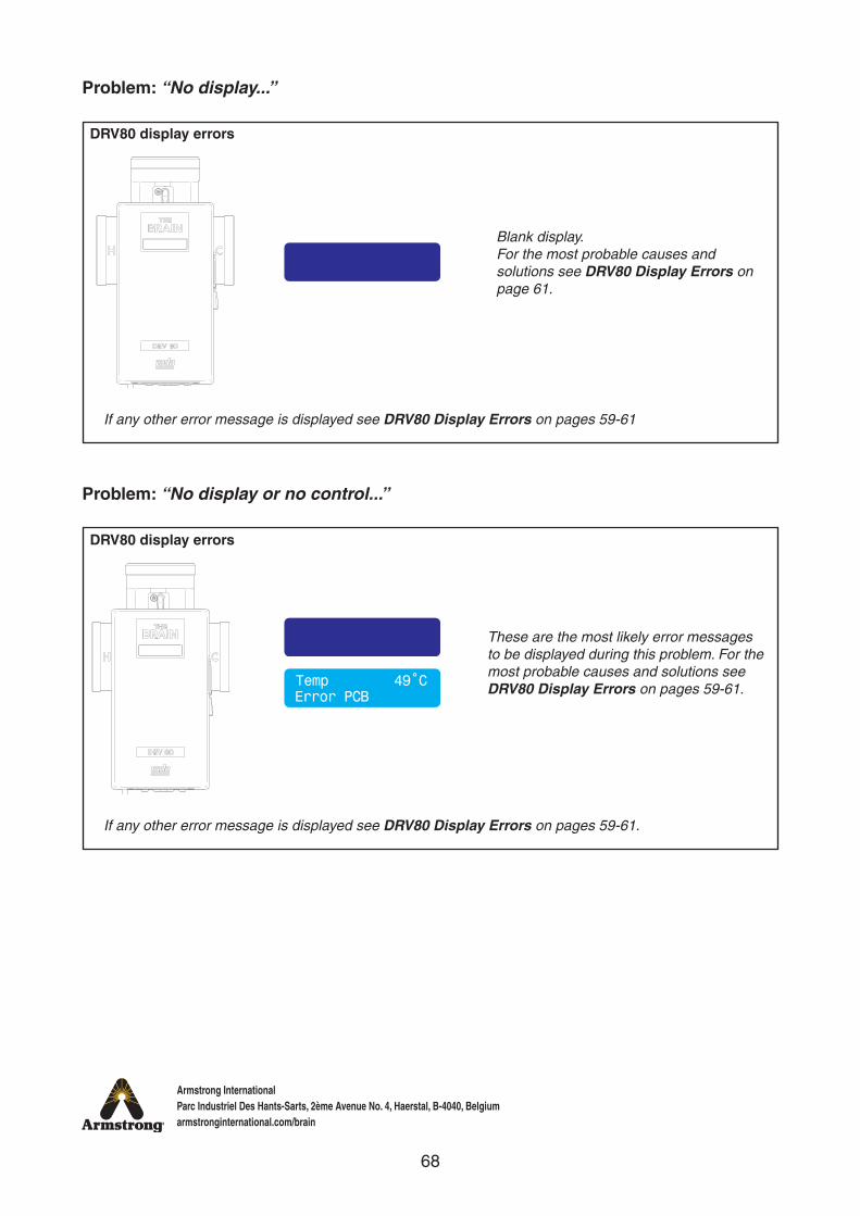
Problem: “No display...”
Problem: “No display or no control...”
DRV80 display errors
DRV80 display errors
If any other error message is displayed see DRV80 Display Errors on pages 59-61
If any other error message is displayed see DRV80 Display Errors on pages 59-61.
Error PCBTemp 49˚C
Blank display. For the most probable causes and solutions see DRV80 Display Errors on page 61.
These are the most likely error messages to be displayed during this problem. For the most probable causes and solutions see DRV80 Display Errors on pages 59-61.
69
Armstrong InternationalParc Industriel Des Hants-Sarts, 2ème Avenue No. 4, Haerstal, B-4040, Belgiumarmstronginternational.com/brain
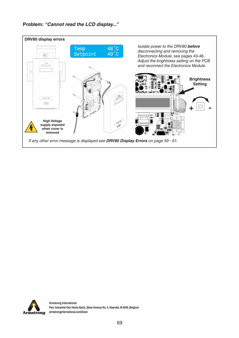
Problem: “Cannot read the LCD display...”
DRV80 display errors
If any other error message is displayed see DRV80 Display Errors on page 59 - 61.
Temp 48˚CSetpoint 49˚C
Isolate power to the DRV80 before disconnecting and removing the Electronics Module, see pages 43-46. Adjust the brightness setting on the PCB and reconnect the Electronics Module.
Brightness Setting
+ -
High Voltage supply exposed when cover is
removed
70
Armstrong InternationalParc Industriel Des Hants-Sarts, 2ème Avenue No. 4, Haerstal, B-4040, Belgiumarmstronginternational.com/brain
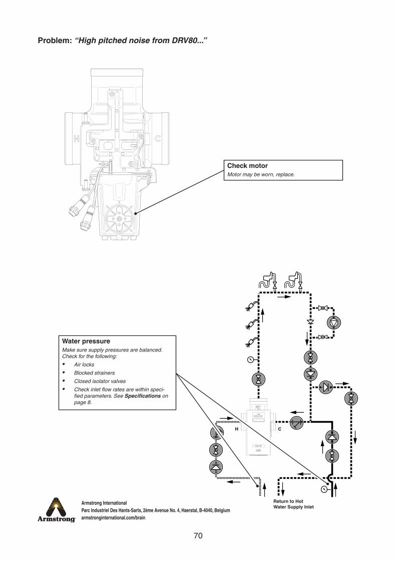
Problem: “High pitched noise from DRV80...”
Check motorMotor may be worn, replace.
H C
Water pressureMake sure supply pressures are balanced. Check for the following:
• Air locks
• Blocked strainers
• Closed isolator valves
• Check inlet flow rates are within speci-fied parameters. See Specifications on page 8.
Return to Hot Water Supply Inlet

71
Armstrong InternationalParc Industriel Des Hants-Sarts, 2ème Avenue No. 4, Haerstal, B-4040, Belgiumarmstronginternational.com/brain
Problem: “Water leaking from DRV80...”
Check all DRV sealsCheck all internal seals for wear and / or damage. Clean and refit seals. If problem persists, replace seals. Only use silicone based lubricants on rubber seals in cartridge (see page 53).
Check drain plugCheck drain plug and seal for wear and / or damage. Make sure drain plug and seal are fitted and tightened adequately. If problem persists, replace both plug and seal.
Check inlet and outlet connectionsCheck inlet and outlet thread joints. Check a correct seal has been made with PTFE thread sealing tape or liquid sealant. Oil-based, non-setting joint compounds should not be used.
DRV body failureDRV80 replacement required.
72
Armstrong InternationalParc Industriel Des Hants-Sarts, 2ème Avenue No. 4, Haerstal, B-4040, Belgiumarmstronginternational.com/brain
Armstrong Hot Water, Inc. (“Armstrong”) warrants to the original user of those products supplied by it and used in the service and in the manner for which they are intended, that such products shall be free from defects in material and workmanship for a period of one (1) year from the date of installation, but not longer than 15 months from the date of shipment from the factory [unless a Special Warranty Period applies, as listed below]. This warranty does not extend to any product that has been subject to misuse, neglect, or alteration after shipment from the Armstrong factory. Except as may be expressly provided in a written agreement between Armstrong and the user, which is signed by both parties, Armstrong DOES NOT MAKE ANY OTHER REPRESENTATIONS OR WARRANTIES, EXPRESS OR IMPLIED, INCLUDING, BUT NOT LIMITED TO, ANY IMPLIED WARRANTY OF MERCHANTABILITY OR ANY IMPLIED WARRANTY OF FITNESS FOR A PARTICULAR PURPOSE.
The sole and exclusive remedy with respect to the above limited warranty or with respect to any other claim relating to the products or to defects or any condition or use of the products supplied by Armstrong, however caused, and whether such claim is based upon warranty, contract, negligence, strict liability, or any other basis or theory, is limited to Armstrong’s repair or replacement of the part or product, excluding any labor or any other cost to remove or install said part or product, or, at Armstrong’s option, to repayment of the purchase price. As a condition of enforcing any rights or remedies relating to Armstrong products, notice of any warranty or other claim relating to the products must be given in writing to Armstrong: (i) within 30 days of last day of the applicable warranty period, or (ii) within 30 days of the date of the manifestation of the condition or occurrence giving rise to the claim, whichever is earlier. IN NO EVENT SHALL ARMSTRONG BE LIABLE FOR SPECIAL, DIRECT, INDIRECT, INCIDENTAL OR CONSEQUENTIAL DAMAGES, INCLUDING, BUT NOT LIMITED TO, LOSS OF USE OR PROFITS OR INTERRUPTION OF BUSINESS. The Limited Warranty and Remedy terms herein apply notwithstanding any contrary terms in any purchase order or form submitted or issued by any user, purchaser, or third party and all such contrary terms shall be deemed rejected by Armstrong.
Special Warranty Periods are as follows:
The Brain - Model DRV80 shall have a 5-year parts warranty on all components other than preventative maintenance service items, mentioned on page 42, which includes batteries and all ‘wetted’ O-rings / Seals.
© 2016 Armstrong International, Inc.
Designs, materials, weights, performance ratings and prices are subject to change without notice.
IOM-1079-K2-B Kohler Mira Limited, April 2016
Limited Warranty and Remedy