the brazilian pipeline community - brazil oil and gas brazilian pipeline community supplement to...
TRANSCRIPT

The Brazilian Pipeline Community
Supplement to
Brazil oil & gas
Norway oil & gas
Saudi Arabia oil & gas
EPRASHEEDsignature series
www.eprasheed.com
Brazil oil & gas
Norway oil & gas
Saudi Arabia oil & gas
Pipeline Technology Centre

Liquid PiPeLines and TerminaLsMarcelino Guedes – Director, Petrobras Transporte
a free sTanding hyBrid riser for deePwaTerFrancisco E. Roveri – Petrobras R&D – CENPES
ProjeCTs and ConsTruCTion of new oiL and gas PiPeLines in BraziLBreno de Souza e Silva & Ney Passos – Petrobras Engineering
PiPeLine inTegriTy ProgramPaulo de Tarso Arruda Correia – Petrobras Transporte
BraziL’s PiPeLine TeChnoLogy CenTer – CTduTRaimar Van den Bylaardt – CTDUT
soCiaL and environmenTaL resPonsiBiLiTyAna Paula Grether de Mello Carvalho
suBmarine PiPeLine insPeCTionClaudio Camerini & Miguel Freitas
PiPeLine and shiPPing TeChnoLogy suPPorTs PeTroBrasCésar José Moraes Del Vecchio, Petrobras R&D – CENPES
The BraziLian gas TransPorTaTion sysTemMarcelo Renno – Director, Petrobras Transporte
rouTe seLeCTion and sTruCTuraL design for The goLfinho gas exPorT PiPeLineMarcelo José Barbosa Teixeira, Claudio Roberto Mansur Barros, Mônica de Castro Genaio, Carlos Terencio Pires Bomfimsilva, Vivianne Cardoso Pessoa Guedes, Janaina de Figueiredo Loureiro
Contents
EPRASHEEDsignature series
www.eprasheed.com
Brazil oil & gas
Norway oil & gas
Saudi Arabia oil & gas
The Brazilian Institute of Petroleum and Gas (IBP) with the support of its Pipe-line Commission has been working to develop Brazil’s pipeline industry by helping companies in this sector oper-ate in a profitable, efficient, ethical and socially responsible way.
In this context, the Commission pro-motes the exchange of ideas and ex-perience amongst professionals in this industry and is active in the areas of norms standardization, promoting in-ternational trade missions and in the organization of courses and events.
Among the latter we can highlight the Rio Pipeline Conference and Exhibi-tion as a world class forum to debate the major issues facing the international pipeline industry.
Brazil oil & gas
Norway oil & gas
Saudi Arabia oil & gas
Brazil has the potential to export world class technology and services. For this to happen, an export culture needs to be cultivated. Part of this culture is a single source of technical material that focuses on Brazil while including the wider international observers. This supplement ‘The Brazilian Pipeline Community’ is a channel for companies, both oil and service to share expertise with the wider export market.
editorsAndre Raposo, Daniel Brossi, Breno Souza, Ney Passos, Francisco Roveri, Pedro Barusco, Paulo Correia, Ana Paula Carvalho, Marcelo Renno, Marcelo Teixeira, Claudio Barros, Monica Genaio, Carlos Pires, Vivianne Guedes, Janaina Loureiro.Contact: [email protected]
PublisherWajid [email protected]
managing editorMajid [email protected]
João Carlos de Luca President, IBP
Wajid Rasheed CEO & Founder, EPRasheed
The Brazilian Pipeline Community

Paulo Roberto Costa – Director Petrobras Bunkering
Strategically important to supply energy to Brazil, Petrobras’ pipeline network operates in strict accordance with Health, Safety and Environmental standards.
Through advanced monitoring technology, we can guarantee the safe transportation of raw materials and products at competitive costs.
Eloi Fernandez y Fernandez – Director General, ONIP (The National Petroleum Industry Organisation)
Since 1999, ONIP has been working to increase local content in oil and gas projects in Brazil. For the pipeline sector, we have recently released a publication, entitled ‘Who is Who in the Pipeline Industry in Brazil’. Our main objective here, is to present local capacity to investors, as we are very optimistic about the future of the Brazilian pipeline industry.
Renato Duque – Director Petrobras Services
Raising professional skills and implementing new pipeline construction and monitoring technologies are our challenges.
Our goal is to expand the pipeline network in a safe and efficient manner while minimising environmental impact.
Ildo Sauer – Director, Petrobras Gas and Power Area
Petrobras is changing from an oil company into an integrated energy Company. Natural gas is playing a fundamental role in the organization as its share of the Brazilian energy matrix increases. As a result, the investments allocated for the natural gas chain in the 2007-2011 period amount to US$22.1 billion, a 71 percent increase over the previous budget.
Sergio Gabrielli – President, Petrobras
Over the next few years we will be witnessing the third boom in pipeline activity in Brazil. Building new oil, natural gas and bio-fuel pipelines will be our challenge.
We will look to new technologies to ensure environmental and operational safety with social responsibility.
Sergio Machado – President, Petrobras Transporte
Transpetro has prepared itself to meet increas-ing demand generated by self-sufficiency and the growth of Brazil’s oil and gas sector. New ships, terminals and pipelines will guarantee logistical supply in a country that has the dimensions of a continent. Acquired over the last 30 years, our experience of Ethanol logistics places our company as the industry benchmark and market leader.
The Brazilian Pipeline Community viewpoints

Transpetro is present in the whole of Brazil, through the operation of 44 terminals and a pipeline net-work of around 7,000 km of oil pipelines, operating from the north of the country in the Amazon re-gion – pipelines ORSOL I and II and terminals in Coari, Manaus and Belém – to the extreme south – Rio Grande Terminal. With an infrastructure of around 500 stor-
Marcelino Guedes, Director - Petrobras Transporte
age tanks for oil and oil products, in addition to 80 globes for LPG, Transpetro has the installed capac-ity to store approximately 10 mil-lion m³ and transport around 53 million m³/month of oil and oil products, in addition to handling around 4,600 shipping operations per year. Complementing the in-frastructure of these terminals, Transpetro owns two multiple
buoy mooring systems and five mono-buoys, with the objective of unloading in locations where the coastal conditions do not allow the mooring of ships.
operational safety
Transpetro maintains the consistent policy of improving the safety of its operations. In the Pipeline Integrity
Liquid Pipelines and Terminals
The Brazilian Pipeline Community Liquid Pipelines and Terminals – guedes

Liquid Pipelines and Terminals
Program (PIP) alone, US$ 630 mil-lion have been invested – with the result being a reduction in the vol-ume of leaks to the order of 93%. PIP, which is destined to ensure per-fect functioning of the installations and reliability of operations, has been continuously revised and has gained new monitoring tools.
The implementation of the Terminal Integrity Program (TIP) began in 2005. This will establish a series of technical projects with the objective of achieving excellence in the safety and integrity of the installations and infrastructure of the units. The in-tegrity programs for pipelines (PIP) and terminals (PIT), which include stabilization of the slopes, renova-tion of piers and storage tanks are being enhanced by the training of the workforce.
The National Operational Control Center (NOCC) ensures the stand-
ard of safety for the operational control of the pipeline network throughout Brazil. From there, the technicians accompany remotely and in real time the operations in the pipelines. NOCC is equipped with computers and the leading edge technology. Supported by the Supervisory Control and Data Acquisition (SCADA) software, the operators receive immediate detailed information about what is happening in the pipelines and monitor the levels of flow, pressure, temperature and density of the oil and the gas. At the least sign of any abnormality, the system allows for telecommand interventions such as the switching on or off of pumps, or the opening or closing of valves in any stretch.
Pipelines and terminals, just like all of the Transpetro installations, comply with norms that go beyond the regulatory demands, having the
voluntary certifications for the In-tegrated Management of Quality, Health, Safety and the Environ-ment (QSMS) – ISO 9001 (qual-ity), ISO 14001 (environment) and OHSAS 18001 (international norm for occupational safety) – be-ing evaluated by international certi-fying agencies.
Within the projects aimed at in-creasing operational safety pipe-lines, is the Program for the Greater São Paulo Outflow Logistics Refor-mulation. The project, with invest-ment of around US$1 billion, sub-stitutes the existing pipeline network installed in the metropolitan region of São Paulo, with an external net-work. The objectives are to provide the network with the capacity to handle growing volumes of oil, oil-derivatives and other products. And to reduce the safety risks associ-ated with heavy urbanisation along pipeline rights-of-way in Greater São Paulo.
In addition to all the care taken with operational safety, Transpetro maintains an infrastructure to re-spond to emergencies that includes a Center for Emergency Pipeline Repairs (CREDUTO) in Guarul-hos – São Paulo, and 49 Emer-gency Response Centers (CREs and CDAs) spread around the country, with equipment and teams trained for a rapid response to any accident with a possible impact on the envi-ronment.
new Projects
The increase in the price of oil and the growth in demand for fuels with less impact on global warming have led to the search for biofuels. In Brazil, the Transpetro Program for Ethanol Logistics gained impetus due to the Brazilian experience with alcohol technology, and the prediction that by 2014 demand for
CREs – Transpetro Management – 34CDAs – Petrobras Management – 9Advanced CDA Bases – 6
Liquid Pipelines and Terminals – guedes
graphic shows Petrobras emergency Bases

ethanol will reach 25 million m³ in the domestic market and 5.5 million m³ abroad. Transpetro is preparing to increase its capacity of fuel ethanol outflow from the present 1.2 million m³ per year to 9.4 million m³ per year in 2015, with investments in exclusive pipelines and tankage in the Southeast, the South and the Northeast of Brazil amounting to US$532 million. The principal investments are as follows:
• Ethanol pipeline Paulínia-Guarar-ema: exclusive pipeline for ethanol with the capacity for eight million m³ per year with an investment of US$ 154 million.
• Ethanol pipeline Uberaba-Ribei-rão Preto-Paulínia: capacity to transport four million m³ per year-with an investment of US$100 million.
• Tietê-Paraná Waterway: capac-ity for transporting four million m³ of ethanol per year from the
west of São Paulo, Mato Grosso and Goiás to Paulínia and take the same quantity of diesel oil and gasoline from Paulínia back to these regions. The investment is US$ 236 million.
• Ethanol pipeline Guararema-São Sebastião: capacity for four mil-lion m³ per year. The investment is still being evaluated.
• Construction of three more tanks at the Maceió Terminal, increas-ing the capacity from 400,000 m³ per year to 700,000 m³ per year. The investment is US$ 4 million.
• Paranaguá Terminal: adaptation of an existing tank, construc-tion of two additional tanks and a platform for tanker trucks with the enlargement of the wagon platform to increase the capac-ity from 400,000 m³ per year to 700,000 m³ per year. The invest-ment is US$ 4 million.
The highlight among the new projects for oil pipelines is the study for the implantation of a pipeline of around 1,400 km between the REPAR Re-finery in Araucária and the cities of Londrina, Campo Grande and Cui-abá, with the objective of reducing the logistics cost of transporting oil products to the central-west region, meeting the growing demand gener-ated by the expansion of agribusiness in that area.
The increasing demand for natural gas in Brazil, predicted to grow by 14% per year to 2010, accompanied by the need for diversifying supply, has led to the acceleration of projects for water-based terminals with the capacity to receive, vaporize and dis-patch natural gas. For this purpose, projects are being developed for the implantation of terminals capable of receiving ships carrying Lique-fied Natural Gas (LNG) initially in Ilha D’Água – Rio de Janeiro, in the southeast of Brazil and in PECEM – Ceará, in the Northeast.
graphic shows schematic of Pipelines
The Brazilian Pipeline Community

introduction
Petrobras is considering the single-line FSHR (Free Standing Hybrid Riser) design as an option for large diameter export risers in deepwater. This large bore specification com-bined with the deepwater environ-ment put this application outside the present feasibility range of solu-tions such as flexible pipes and steel catenary risers (SCRs). Both these solutions present high top tension loads for installation and operation. The lateral buckling failure mode in flexible pipes and the fatigue damage in the touch down zone (TDZ) of SCRs are further design limitations currently only solved by the use of heavier pipes which further compro-mise hangoff loads in a negative de-sign spiral.
The FSHR system has a reduced dynamic response, as a result of significant motion decoupling be-tween the Floating Production Unit (FPU) and the vertical portion of the FSHR system and its vessel in-terface loads are small when com-pared with SCRs or flexible pipe so-lutions. Therefore it is an attractive alternative solution for this kind of application. There are further cost savings associated with this concept due to the added advantage of hav-ing the riser in place prior to the installation of the FPU.
new riser development– a free standing hybrid riser for deepwaterFrancisco E. Roveri – Petrobras Research & Development Center – CENPES/Subsea Technology Group
The hybrid riser concept, which combines rigid (steel) pipes with flexible pipes has been utilized by the offshore industry since the 80’s. The Riser Tower first installed by Placid Oil at Gulf of Mexico in Green Can-yon 29 was refurbished and re-uti-lized by Enserch. More recently, the concept underwent some changes for application at Girassol field in Angola, where three towers were installed by Total. The Riser Towers at Girassol field are positioned with an offset with regard to the FPU, whereas at GC29 the vertical por-tion of the riser was installed by the semi-submersible FPU and was lo-cated underneath the derrick.
Five water and gas injection monobore FSHRs (10 to 12-inch) have recently been installed in West Africa offshore Angola, at Kizomba field in about 1200 meters water depth. The design of these risers has some key differences to one of the concepts presented in this pa-per, each of which offers different design and operational advantages. Riser towers are being developed for installation in the Greater Plutonio and Rosa fields in Angola.
Petrobras has been studying the hy-brid riser concept for some years. In 1989 a feasibility study was developed for Marlim field, Campos Basin, for a configuration similar to the one uti-
lized by Placid. After a long period, it was only in the year 2000 that this al-ternative was considered for concep-tual studies at Albacora Leste field, in 1290 meters water depth, for the P50 turret moored FPSO.
Two alternatives were considered for comparison: a Steel Lazy Wave Riser (SLWR) and a concept combining rigid and flexible pipes. In 2003 Petrobras contracted the concep-tual study development of the Riser Tower solution for the starboard side 8-inch production lines of the P52 semi-submersible platform. Two towers were considered, each com-prising seven production lines and one spare line. In 2003 Petrobras also contracted the feasibility stud-ies of an export oil FSHR to be con-nected to a semi-submersible plat-form in water depths of 1250 and 1800 meters.

system description
The FSHR design may have a number of variants. Two configurations are presented hereinafter, the main dif-ference being the interface between the Buoyancy Can (BC), the vertical pipe and the flexible jumper.
Configuration a
The configuration described below is considered for an oil export riser to be installed from a MODU (Mobile Offshore Drilling Unit), due to the availability of such vessels already under contract at Campos Basin.
The FSHR consists of a single near vertical steel pipe connected to a foundation system at the mud line region. The standard riser joints are 18-inch OD x 5/8-inch wall thick-ness X65 material. The riser is ten-sioned by means of a BC, which is mechanically connected to the top of the vertical pipe. The vertical pipe is always kept in tension in order to maintain the FSHR stable for all the load cases. The BC is 36.5 m long x 5.5 m diameter. It has 16 compart-ments and the maximum upthrust is about 570 Te. The BC is located 175 meters below the sea level, therefore beyond the zone of influence of wave and high current.
The FSHR runs from the hangoff slot at FPU to the Pipeline End Ter-mination (PLET) located near the riser base. The lower end of the verti-cal part interfaces with a stress joint. Below the stress joint there is the offtake spool, which connects to the foundation by means of a hydraulic connector. A rigid base jumper con-nects the mandrels located at the offtake spool and PLET, providing the link between the FSHR and the pipeline. The foundation pile will be drilled and grouted and may typical-ly be offset from the FPU by more than 200 meters.
The riser pipe passes through an in-ner 36-inch OD stem within the BC, and is guided within the stem by cen-tralizers. Where the riser pipe is sub-ject to high bending loads such as the keel ball centralizer on the BC, taper joints are used to reduce the stress in the riser pipe. The BC is secured to the riser pipe at the top of the BC by means of a bolted connection.
At the top of the free-standing riser is the gooseneck assembly. This as-sembly consists primarily of the gooseneck and an ROV actuated hy-draulic connector which allows the gooseneck and flexible jumper to be installed separately from the vertical section of the riser. Attached to the
gooseneck is the flexible jumper. The flexible jumper connects the free-standing section of the riser system to the vessel, and includes bend stiff-eners to ensure that the range of ro-tations experienced at the end con-nections do not damage the jumper due to low radius of curvature. The flexible jumper has enough compli-ance such that the vessel motions and offsets are substantially decou-pled from the vertical portion of the FSHR system, and consequently the wave-induced dynamic response of the free standing riser is low.
Configuration B
The position of the gooseneck in relation to the BC is the main dif-ference between the West African and Configuration A designs. In the earlier design, the gooseneck is posi-tioned below the BC and the verti-cal riser is tensioned by the can via a flexible linkage or chain.
This arrangement simplifies the inter-face between the BC and vertical riser, and allows pre-assembly of the flex-ible jumper to the gooseneck before deployment of the vertical riser. How-ever, in the event of flexible jumper replacement or repair, an elaborate jumper disconnection system needs to be employed below the BC.
fig. 2 presents Configuration B.fig. 1 shows Configuration a.
The Brazilian Pipeline Community riser development – roveri
Positioning the gooseneck at the top of the BC allows for independent in-stallation of vertical riser and flexible jumper. A flexible pipe installation vessel can install the flexible jumper when required. This minimizes the risk of damage to the flexible jumper during installation as the procedure is similar to that of a shallow water flexible riser with the first end at the top of the BC. This design also facilitates and minimizes the time for flexible jumper retrieval in case of damage, in service, to any of its components such as the stiffener, end-fittings or pipe outer sheath.
On the other hand, it is necessary to have a continual vertical riser string right through the centre of the BC to provide a connection hub for the flexible jumper at the top. This ar-rangement introduces interfaces be-tween the riser string and BC which have to be carefully analyzed and engineered. In addition, installation analysis has to be conducted to assess the loads on the riser string during
deployment through the BC. Other differences are the foundation type (suction piles x drilled and grouted pile) and bottom interface (flexjoint x tapered stress joint).
Configuration B presents the goose-neck positioned below the BC. The vertical riser is tensioned by the BC via a flexible linkage or chain and the hub is in offset with regard to the vertical section of the FSHR. This allows the flexible jumper to be installed in a similar way as Configu-ration A, therefore overcoming some disadvantages of this configuration and previous designs.
Conclusions
In the FSHR design concept, the location of the BC below high cur-rent and wave zone, and the use of the flexible jumper to significantly decouple vessel motions from the vertical riser greatly reduce the sys-tem dynamic response, resulting in a robust riser design particularly
suited to deepwater applications. The design is relatively unaffected by severe environmental loading or non-heave optimized host vessels when compared to SCRs and flex-ible risers. The robustness allows the riser to be conservatively analyzed, and allowances for design changes and uncertainties to be included up-front in the design process, thus giv-ing greater confidence in the overall system design.
For engineering, procurement and construction (EPC) contractors not having a suitable vessel, or unable to mobilize their vessels to install the FSHR, the ability to use a MODU as the installation vessel could prove to be an attractive alternative.
It can be said that the FSHR concept extends the reach of deepwater riser feasibility as it avoids the main techni-cal problems faced by other solutions, and arguably, it may be among the few proven riser concepts feasible for deepwater large bore applications.
Always innovating for the best
Azevedo & Travassos develops innovative solutions to meet the needs of its Oil and Gas clients. Consequently, it is recognized as one of Brazil’s Foremost Construction Companies with the best know-how in the market.
The result of this investment can be described by a single word: credibility.In the end, those that have been working for so long, can only do things well.
riser development – roveri

general Considerations
In light of ever-growing gas demand and the increasing difficulty of meet-ing such demand through gas im-portation, Petrobras envisaged Bra-zilian self-sufficiency in natural gas production and is accelerating the process of achieving it. Today, the consumption of the country is 45.5 million cubic meters per day and by the year 2011, it may reach 121 mil-
Projects and Construction of new oil and gas Pipelines in Brazil
lion cubic meters per day, of which 71 million will be produced in do-mestic fields.
Additionally, the demand for trans-portation of crude oil and deriva-tives is also growing. The installation of new refining units and the re-vamping of some existing ones were required to meet a growing market, which ranges from fuel consump-tion to petrochemicals. The Brazil-
ian consumption of oil derivatives in 2005 was 1.766 thousand bpd, with an estimated growth of 3.1% p.a in the next five years, reaching a expected consumption of 2,117 thousand bpd in 2011.
Such is the background to the in-vestment plan of the oil and gas pipeline network expansion in the country, bringing about new jobs as well as new technologies. In or-
Breno de Souza e Silva & Ney Passos – Petrobras Engineering
The Brazilian Pipeline Community

Projects and Construction of new oil and gas Pipelines in Brazil
der to meet the demands of the gas market and make it possible for field production flow, Petrobras is investing US$ 4.4 billion in the next five years in the enlargement of the gas pipeline network. With respect to the increase in oil pipe-lines and terminals, the expected investment for the next five years is US$ 3.0 billion.
Pipeline Projects
Regarding projects and construc-tion of oil and gas pipelines, the actions taken by the Engineering department of Petrobras have al-ready shown practical and visible results.
In the Northeast region of the country we find unmet gas demand, which has resulted in increased in-vestments in the transportation and distribution infrastructure, mostly based on thermoelectric plants for power generation.
The Southeast region already has a booming transportation and distri-bution network, especially in Rio de Janeiro and São Paulo, where gas consumption is high. The projects to expand pipeline network are also encouraged by the growth of the piped gas distribution network in the metropolitan regions as well as the demand related to industry and thermoelectric plants.
If we only consider existing oil and gas pipelines we may note that our gas pipeline system in Brazil is not wholly integrated. However, the unmet demand from the Northeast, the first production from fields in the Espírito Santo and the promis-ing Southeastern market will be in-terconnected by the GASENE Gas Pipeline.
For these gas pipeline networks, 10 compression stations are envis-
aged which will either be rented or owned by Petrobras. This will result in roughly 30 turbo-compressor sets with installed power varying from 7.200 HP to 23.800 HP each.
Petrobras is also investing in the development and improvement of the operating and safety conditions of terminals and pipelines, many of which are in urban areas. To this ef-fect, the São Paulo Master Pipeline Plan (PDD-SP), foresees transporta-tion of oil, derivatives, natural gas and alcohol through a new pipeline and right-of-way network introduc-ing optimized operating logistics and substituting the existing network, which will interconnect terminals and distribution companies in the state of São Paulo. The purpose of such modifications are the adapta-tion of paths and strips of land along the pipelines’ route so that they blend in better with the surrounding communities, as well as preparing the network to cope with the growth of the state of São Paulo.
The petrochemical complex of Rio de Janeiro (COMPERJ) will also require the construction of new pipelines, in-cluding crude oil and petrochemical.
It is worth noting that Petrobras faces considerable challenges with regard to the construction of oil and gas pipelines. There is an exten-sive oil and gas pipeline that needs to be implemented and operated in a safe and socially responsible way. And time runs short as the number of projects increase. To rise to such challenges Petrobras is counting on technological innovations, which are under development. Society is also called to provide the necessary resources as qualified manpower and a competitive and efficient in-dustry to supply equipment and material of proven quality. It is worth mentioning the national oil and gas industry mobilization pro-
gram (PROMINP) developed by the federal government.
The issues related to health, safety and environment cannot be forgot-ten. The works to be implemented require social responsibility and maximum care and respect to the particular characteristics of the re-gions crossed by the pipelines.
To provide efficient outflow of large volumes, pipelines with greater diam-eters and higher pressure ratings are required. Increasing steel resistance means avoiding greater thickness of pipe. The benefits include saving steel by weight reduction, and therefore, the costs of pipe purchasing, pipe construction and assembly are all re-duced.
At present, the oil and gas pipelines of greatest resistance in Brazil are manufactured with pipes of X70 degree in conformity with API 5L specification, which has reliable con-struction and assembly techniques. On the other hand, Petrobras has participated in many attempts to in-novate pipe fabrication technology, such as the study of fabrication and application of API 5L X80 pipes, the evaluation of new welding pro-cesses for highly resistant steels, the study for application of pipes with helicoidal welding, as well as its par-ticipation in the working out of the Brazilian standard for heat bending by induction.
Conclusion
The expansion of Brazil’s oil and gas pipeline network is a fundamental necessity in order for the economic growth of our country.
The Engineering Department of Petrobras is fully committed to this goal and is not sparing any efforts in order to develop the new technology required to complete new projects.
souza & Passos

introduction
The project is part of the PEGASO Program – (Operational Safety and Excellence in Environmental Man-agement). It started in 2001, with a large and intense pipeline physi-cal integrity recovery program, followed by the adjustment of the company’s pipeline grid (more than 9,650 km of natural gas, oil and oil product pipelines) and led to the new Petrobras Integrity Standard or PID (Padrão de Integridade de Dutos).
The Program was started after three pipeline accidents in the country; the first one in Guanabara Bay with a fuel oil line (PEII 16”, 13.7 km) in Janu-ary/2000, resulting in a leakage of 1300 m3; the second in a crude pipe-line in July/2000 (OSPAR 30”, 118.5 km) with 4000 m3, lost and the third one in a diesel pipeline (OLAPA 12”, 94.0 km) with 150 m3 lost in 2001. A fourth accident with a fuel oil pipe-line (OBATI 14”, 50 km) happened in May/2001 due to external corro-sion resulting in a leakage of 200 m3 of atmospheric residue, and a fifth in July/2001 in OBATI Clean products 14” pipeline due to Third Party Ac-tion also resulting in a leakage of 200 m3 of LPG.
Transpetro has invested more than US$600 million to date, aiming to adjust its pipeline network to the new level of integrity demanded by PID.
Paulo de Tarso Arruda Correia, Petrobras Transporte S. A. – Transpetro
Transpetro Pipeline integrity Program
This new standard began establishing routines for inspection, control and mitigation for what were called four main failure modes: Internal Corro-sion; External Corrosion, Third Party Action; Pipe and Soil interaction.
The PID document comprised eight chapters covering: Risk Analysis; In-ternal Corrosion; External Corrosion; Third Party Actions; Soil and Pipe Interaction (Geotechnical Problems); Pigging; Defect and Repair Analyses; Pressure Testing.
All these PID chapters were applied to each pipeline in the company’s network in a way that the control of the program was carried out per pipeline.
Program structure
The program as a whole, delivered a reduction in the leakage volume from 6,000 m3 in 2000, to less than 39 m3 in 2003, the leakage has been kept at a very low level since then.
Three phases and five processes were identified. These were the ‘Emer-gency Phase’ to rapidly recover the physical integrity of a set of priori-tised pipelines. This included the as-sessment and recovery of integrity as well as adjusting the whole pipeline network to the Petrobras Pipeline Standard. Additionally, it included the introduction of the Pipeline
Standard as a permanent practice of the company.
The emergency Phase
This was applied to a priority list of 96 pipelines (6,084.9 km) selected for strategic and risk reasons. These were selected from among the 183 pipelines (9,650 Km) that would be considered in the whole program.
In this emergency phase, more than 245 km of new and different pipelines, representative of the in-stalled base considering items such as nominal diameters, material and wall thicknesses, were purchased and used to assist in the repairs that came after an in-line inspection program, using MFL or ultrasonic pigs.
A total of 5,480.1 km of pipeline was inspected through intelligent pigs (geometric, high resolution
The Brazilian Pipeline Community

Transpetro Pipeline integrity Program
MFL and ultrasonic) resulting in the repair of 5,200 defects. This re-sulted in 5,094.3 km of rehabilitat-ed pipeline. During this phase more than 87 new employees were hired to work in the integrity area and al-most US$400.00 million were in-vested.
This phase started in early 2001 and ended in 2003 (the target was 07/2002 but the repairs continued until mid 2003).
The adjustment to Petrobras Pipeline standard
In this phase all Pipeline standard-ization actions were applied to each pipeline through a variety of differ-ent projects and according to a WBS (Work Breakdown Structure).
The management of the program considered a structure composed of five Committees, one in headquar-ters and one in each of Transpetro’s regions.
Typically, the Regional Com-mittees brought together repre-sentatives of the following areas: Health, Safety and the Environ-ment; Commercial; Marine Ter-minals; Oil Pipelines; Gas Pipe-lines; Engineering.
The Regional Committee promot-ed periodic coordination meetings where the different agents had the opportunity to exchange ideas, update each other regarding the progress in their activities, discuss
problems, etc. The headquarter's committee performs the whole program coordination, issuing a monthly report and keeping a spe-cific site on the company home page.
Transpetro has created a standard, negotiated with the ILI services pro-vider companies, for the format of pig inspection reports (magnetic and hard copy) that make the interpre-tation easier as well as the data pro-cessing, using a toll that estimates the wall resistance, the defects that must be repaired as well as defining the next inspection (described be-low) called Planpig.
Planpig is a novel methodology de-veloped by Transpetro for pipeline management in-line inspection pro-grams.
This software was developed to determine the best (risk and cost based) time interval between in-line inspections and the preventive re-pairs to be carried out following a pipeline inspection. The innovative feature of this methodology is that it takes into account the expected fail-ure cost, the cost of inspection and the cost of repair to determine the optimal failure risk at the moment of inspection as well as the ILI tool accuracies and internal and external corrosion rates.
By applying this methodology a re-duction of 46% in the expenditure on in-line pipeline inspection was obtained.
After a careful experimental research program, Petrobras developed a self-integrity criterion for the assessment of pipelines with corrosion defects. The RPA methodology may be used alternatively for ASME B31-G, gen-erating a reduction of 49% in the preventive repairs carried out after in-line inspections.
Petrobras also has a laboratory de-voted to the development and tests of smart-pig tools in its Research Center, CENPES. This laboratory has developed tools of different types such as Geometric, MFL, pressure and temperature profiler with an accelerometer and new technology for internal corrosion and geometry deploying the polygraph principles. The following areas have been re-searched:
internal Corrosion (iC)
In order to control and mitigate the IC, the project in this area comprised the following main items:
Implantation of infra-structure in-cluding:
• Petrobras project and installation of corrosion coupon and Electri-cal Resistance Corrosion Probes (ERCP) in the 6o/c position (bot-tom line of the pipes).
• Development of new corrosion inhibitor additives, injection sta-tions and updating the existing units with automation.
Implementation of a set of routine services considering:
Periodical cleaning of the pipelines with scraper pigs: IC management service routine to collect samples from the debris dragged by the scrap-er pigs, NACE test of samples from product batches pumped through the pipelines.
Transpetro's Pipeline Network Quantity Lenth
Regional Nr. Pipelines Nr. Row KM
NNE 42 15 2596,83
SE 60 14 2763,54
SPCO 61 27 3260,00
SOUTH 20 9 1029,90
TOTAL 183 65 9650,28
Transpetro Pipeline integrity Program
external Corrosion (eC)
In EC the project encompassed the fol-lowing items: External coating survey using PCM, ACVG, DCVG and CIPS for mapping and sizing the disconti-nuities in the external coating as well as being a way to provide the mapping of the pipelines at the ROW (Right Of Way) without the mapping tool.
The CPs supervisory system
A great advance in the program was the application of the supervisory system for the CPS.
This system called STR (Sistema de Telesupervisão Remota) is based on a set of sensors installed in the rec-tifiers or the interference current drainage equipment like voltmeters (AC and DC), current meters (DC output current), soil to pipe voltme-ter with a permanent semi-cell and a switch in the entrance door to detect invaders in the rectifier shelter.
The external Coating inspection
The surveys using the methods al-ready described, have proved to be very efficient in pinpointing the ex-ternal coating failures and a lot of re-pairs have been carried out in points where the coating was severely de-graded or did not exist any more. Up to May 2006, a total of 7,626km of the pipeline network, or 79% of total network had been inspected and a to-tal of 3,499km were rehabilitated.
geotechnical or soil/Pipeline interaction
The PID created the requirement to develop a geographic plan produced from aerial photography that allows the identification as well the clas-sification and sizing on a three level scale (severe, medium and moderate), of all geological problems along the pipeline. This plan is called a themat-
ic map, and takes into account the re-sults of special and periodic surveys.
Among the most common problems are: River crossing erosion causing the pipeline exposition leading seg-ments to be without support; Soil movement in mountain slopes (hill-sides); Soil erosion with the exposi-tion of the pipeline by heavy rain; The collapse of the soil by under-ground water movement; The ac-tions of strong waves or strong tides in the sea to beach transition.
risk analyses
The Risk Analyses chapter in the Petrobras Pipeline Standard is one of the most important in the whole document.
It is the qualitative analyses that con-sider the consequence potential and the failure probability of the four fail-ure modes considered in the PID.
The pipelines are divided into seg-ments according to the geographical and environmental factors. The con-sequence potential takes into account: the environmental classification; class location; operational conditions like product, flow rate and pressure (only for natural gas pipelines).
All 183 pipelines in the network had their risk evaluated by this process.
Pressure Test
In the PID standard the pressure test is either mandatory or recommend-ed, based on the following cases:
Mandatory Cases: New pipelines; Af-ter pipeline repair; Pipelines that need to operate under pressure higher than that allowed by the last valid hydro-test; Pipelines in sensitive areas.
Recommended Cases: Pipelines that remain out of use for more
than 5 years, and that need to oper-ate again; Pipelines that have been operating at one pressure level that need to operate at a pressure 25% higher, although lower or equal to the one allowed by the last test. Pipelines that have been operating for more than 25 years without a new valid pressure test; Pipelines out of operation, even in periods lower than 5 years that have not had an appropriate hibernating process. These criteria were applied to the pipeline network, and as a result, 101 pipelines were tested.
r&d in Pipeline, Pipeline Technological Center, Cooperative Projects
Petrobras has in its Research and De-velopment Center (CENPES) a lab-oratory devoted to the development and testing of smart pigs tools. This laboratory has developed Geometric tools, MFL and pressure/tempera-ture profiler.
Recently, Transpetro took part to-gether with other companies in the foundation of an independent and private Pipeline Technological Cen-ter (CTDUT – Centro Tecnológico de Dutos).
Two pipeline loops are being con-structed, the larger one with 12”, 2.4 km for liquids and the smaller one for gas with 14”, 130m.
Conclusion
Transpetro is fully committed to the improvement of the integrity of its pipeline network. It does this through a sound pipeline integrity program which aims to achieve higher safety levels and more eco-nomical operations. The total in-vestment of more than US$600 million covering a broad range of projects as described herein, con-firms this commitment.
The Brazilian Pipeline Community

Transportadora de Gas del Sur S.A. is the leading gas transportation com-pany in Argentina. Not only does TGS operate the longest and oldest pipeline system in Latin America, (7,972 Km of pipeline, 579.090 HP compression power, 74 MMm3/d of contracted capacity), it also renders integral processing services (1 mil-lion tons/year of Ethane, LPG and gasoline), treatment (12 million m3/d) and compression (36,800 HP) of natural gas in gas fields.
These services comprise construc-tion, operation, maintenance and financial structuring.
In the past, the Company overcame the challenge of achieving interna-tional standards in controlling exter-nal pipeline corrosion. Today, consist-ent with its policy of safety, accident prevention and its constant pursuit of quality, TGS has set up – within its Pipeline Integrity Team – a group of specialists and experts devoted to the research and development of a predictive model for finding cracks produced by high-pH stress corro-sion cracking (SCC) in pipelines, thus preventing service interruptions arising from this phenomenon.
Causes and effects
SCC can be observed in pipes as a cracking in the external surfaces of pipelines (generally, lengthwise) gener-ated by the combined action of corro-sion and tension attributed to: pressure variations, high temperatures, pipeline coating conditions, soil components and cathodic protection potentials.
The search for efficient methodolo-gies and practices to detect this kind
Progress in the development of a predictive model for finding locations of significant high-ph stress Corrosion Cracking in gas pipelines.
of cracking has been a priority for TGS since its beginnings.
Currently, the Company is working on two technical fronts to detect and pre-vent SCC effects. On the one hand, we are running in-line inspection tools (TFI & EMAT), to this date with un-certain results, and on the other hand, TGS is developing a susceptibility model. To such purposes, the team of specialists in charge of the task has de-veloped its own soil model.
observable results
The thorough research carried out by TGS' team of specialists is based on geo-morphological surveys of each area, the interpretation of high resolution satellite images, and field works which consist of observation pits, which allow the physical and morphological characterization of the soil and the extraction of samples for subsequent laboratory chemical analysis.
Based on field research and by means of laboratory tests we were able to ob-tain artificial cracking similar to the one found in our system, thus being able to assess, qualitatively and quan-
titatively, the physical and chemical agents involved in this process.
This fact, along with the low resist-ance of the soils where SCC has been found, and the proximity to rectifier facilities, has allowed TGS to present new and unknown vari-ables to be considered in the search for significant SCC.
With the implementation of a reli-able susceptibility model we will be able to predict, with a high degree of certainty, the sites where significant high pH SCC is likely to be found without the need to interrupt the service for its study. It will also al-low us to repair the cracks before a devastating rupture occurs.
Leading the way in the investigation of this phenomenon, TGS keeps in-vesting, developing and researching – together with its team of specialists – the best methodologies to mitigate and prevent SCC, thus successfully rendering excellence and quality in its service.
View of cracks produced by stress corrosion cracking through pipeline wall thickness.
www.tgs.com.ar
sponsored by Tgs

CTDUT is a Technology Center created by Transpetro, Petrobras and PUC-Rio (The Catholic Uni-versity) with support from the Fed-eral Government, resources from the Oil and Gas Sectorial Fund (CTPETRO), and linked to the Ministry of Science and Technology through FINEP. It is a non-profit association open to all companies working in pipeline operation, con-struction, engineering, R&D, train-ing, environment, services, and also government sectors and regulating agencies.
In the search to develop leading edge technology for pipeline transport, CTDUT is emphasized as the fun-damental link in the implantation of a Brazilian network of competence in pipelines, bringing together pipe-line operators, companies, universi-ties, research centers, civil society and government agencies.
The structure built to comprise the technological center is open to all those companies and institutions that wish to strengthen the develop-ment of this project, thus enabling
the multiplication of activities planned for the business and aca-demic sectors.
Nowadays, CTDUT has 19 as-sociates: Azevedo & Travassos, Chemtech, GDK, IMC Saste, In-tec do Brasil Ltda., Intech Engen-haria, Pipeway, TDW, TSA Tubos Soldados Atlântico, TWI, Univer-sidade Federal Fluminense (UFF), Conduto, Brazilian Petroleum & Gas Institute (IBP), Petrobras, PUC-Rio, Transpetro, IEC and Aselco.
CTduTThe ‘Pipeline Technology Center – CTduT’ is a laboratory equipped with field facili-ties for testing/certifying products, full scale simulations and the research and development of new technologies in pipeline activities. CTduT is also designed to offer specialized pipeline training. CTduT contains a pull test unit for Pig testing, an integrity Laboratory for burst tests, a gas flow Loop, and a separate liquid loop for tests under real operating conditions.Raimar Van den Bylaardt – CTDUT
The Brazilian Pipeline Community

CTDUT headquarters is located in the city of Duque de Caxias, state of Rio de Janeiro, close to a Terminal from Transpetro that supplies the center facilities with oil, diesel and natural gas.
The use of the pull test unit began in 1999 to verify the capability of de-tection, the precision of sizing and the absence of false calls. Since then, several tests of pig performance have been done with the goal of testing new technologies, tools for appli-cations, innovative prototypes and adaptations for special case inspec-tions. This pull test unit consists of several pipeline segments installed in a metallic structure containing shelves and an electrically powered winch that moves a wire inside all of the section of the shelves.
some Tests realized in CTduT
The internal coating of pipeline has become more important in in-ternal corrosion prevention. More frequently pipelines are built and assembled with internal coating for reducing friction and assure a better quality of the product. Apart from application coating before pipeline assembly, sometimes the coating is
applied in pipelines in operation. In these cases it is named internal coating in-situ. This kind of appli-cation is more complicated due to the difficulty of surface preparation and the application of the coating itself, that is commonly applied by using pigs. In Brazil, the first in-situ coating application was done in 2002[1]. The average coating thickness is about 300 µm. As with any pioneering work, many tests were performed to assure the qual-ity of this new technology. Part of those tests were performed in CT-DUT pull test unit to check if the MFL tool would damage the coat-ing after a certain amount of runs and verify the influence of the coat-ing in detecting and sizing external defects.
To realize this test a 28m length specimen of pipeline segment was built and assembled into the shelves of the pull test unit. In this segment flanged spools were introduced which had the same coating as the pipeline. After the specimen was as-sembled, an internal inspection was realised by a MFL.
From results of the test, it was con-cluded that when the in-situ coating
was applied, the MFL tool does not damage the coating and nor is its ac-curacy affected by the coating.
Submarine pipelines are quite often more difficult to inspect than on-shore pipelines. The access difficulties and the inadequate design for inspection with pig are the most common reason for naming these pipelines as “unpig-gable”. Other factors also contribute for the difficulty of inspection of those submarine pipeline specially the large thickness and relatively small diam-eters – commonly these pipelines have nominal diameters under 20 inches.
To make inspection feasible of a 12 inch nominal diameter, 3/4 inch thick submarine pipeline, a specimen was assembled in the CTDUT pull test unit in order to evaluate the magne-tization capability of a MFL pig. Sev-eral internal and external defects were introduced into the specimen. Some internal defects had their geometry aligned with the longitudinal direc-tion of the pipe to simulate the typi-cal morphology of internal corrosion defects.
The tool applied in this experiment was a magnetic pig. This pig was specially designed to maximize the
14” diameter loop - 120 meters in length.
12” diameter - 2.4km in length with in-tegral supply tanks, pumps, automation and state-of-the-art controls.
CTduT

magnetism to preserve the method sensitivity even in those adverse con-ditions of large thickness and small diameter.
In the first trial the pig did not pres-ent sufficient magnetism, that led to a non-detection of some defects. In the second version the magnetism reached values as specified and all defects were detect.
some Projects in development
Nowadays, CTDUT is working on the construction of 3 loops:
• 14” diameter and 100m in length for liquid transport;
• 12” diameter and 2,4km in length for liquid transport;
• 16” diameter and 2,4km in length for gas transport.
These projects will be used for re-search, test and training, with a par-ticipation of research centers and universities of Brazil, as well as with the operators, service companies and equipment manufacturers.
The following needs had been iden-tified to develop these projects:
• Research and development of new equipment, tools, inspection sys-tems and pipeline protection.
• Flow tests for simulation software approval.
• Tests and certification of equip-ment and control system, protec-tion, corrosion control, inspection and maintenance of pipeline.
• Certification of process and pro-cedures of operation, inspection and maintenance.
• Training and qualification of op-erators and technicians.
references
(1) Lachtermacher, M., Souza Filho, B, Andrade, L.; “Emprego de reves-timento para proteção interna em dutos”; 6ª Conferência sobre Tecno-logia de Equipamentos – 2002; IBP; Salvador-BA, Brasil.
(2) Franzoi, A. Et All; “Inspeção de Oleodutos com Paredes Espessas com Ferramenta MFL – A experiên-cia da Bacia de Campos”; Rio Pipe-line Conference 2005; IBP; Rio de Janeiro – RJ, Brasil.
For more information, contact the Pipeline Technology Center – CTDUT – www.ctdut.org.br.
The Brazilian Pipeline Community

In 2003, Petrobras joined one of the most important corporate so-cial responsibility projects in the world – the UN Global Compact. Since then Petrobras has defini-tively adopted social and environ-mental responsibility concerns as part of its core values. Respecting human and labor rights, protect-ing the environment and fighting corruption are all major challeng-es that face Society. Petrobras is a company that believes that its busi-
social and environmental responsibilityPipeline right-of-way and family based agro-businessAna Paula Grether de Mello Carvalho
ness performance should include economic, social and environmen-tal responsibility.
‘The Agro-ecological Family Farm-ing Project along Pipelines Right-of-Way’ is a joint Petrobras Transporte and ‘Instituto Terra de Preserva-ção Ambiental’ (NGO) and ‘Onda Verde’ (NGO). Launched in De-cember 2005, it has created veg-etable gardens, an agro-industry and an ‘Online Learning Centre’ in the
low income neighborhoods of Nova Iguaçu and Duque de Caxias, in the state of Rio de Janeiro, Brazil.
The focus regions of the project are the low income communities of Ge-rard Danom and Jardim Geneciano in Nova Iguaçu Municipality, close to the borders of Tingua Nature Re-serve, and the low income commu-nity of Amapa in Duque de Caxias Municipality. All of them are crossed by the stretch of pipeline (ROW).

Since most of the dwellers of those communities live below the poverty line, it is crucial to implement so-cial projects that promote job and income generation and encour-age social organization. Moreover, Petrobras Transporte considers ag-riculture a form of fostering closer relations with the population in the neighborhoods on the edge of its underground pipelines, and of pro-tecting its equipment and the pop-ulation against possible accidents caused by third party actions.
‘The Agro-ecological Family Farming Project along Pipelines Right-of-Way’ consists of a five-module agro ecological produc-tion unit, covering a production area of 96,000 m² (100 vegetable gardens of 960 m²), directly serv-ing 100 farming households. The project not only contributes to-ward maintaining the pipelines, in compliance with the safety and en-vironmental standards adopted by the company but also assists low-income households by providing technical support and financing to find better jobs and increase levels income generation.
The novel aspects of the project are the promotion of social inclusion and guaranteeing economic, envi-ronmental and social sustainabil-ity through two main points. First, adopting participative/ongoing diag-nosis and planning methodologies, creating an evaluating and planning culture by the methodology of Par-ticipative Rural Diagnosis (PRD). Second, the objective of placing the organic productions in the market, throughout local and regional pro-duction chains and arrangements, provides ways to add value to the local farm production, including the families in certified production chains.
The methodology of Participa-tive Rural Diagnosis (PRD) aims to perform critical and integrated analysis of the rural reality involv-ing the population and the project technical assistants. The PRD is not a conventional diagnostic process in which specialists collect infor-mation from the farmers then later unilaterally plan the activities of the project. The purpose of PRD is to encourage dialogue between farm-ers and specialists in order to set up
an environment of discussion and analysis of community problems, so that it is possible for different groups to express different opinions on such problems.
By using visual diagrams for collect-ing information, such as a spoken map, flowchart, Venn diagrams and other tools, the local population and the project technical assistants are able to build diagrams and discuss results. The outcome of the work is a collec-tive understanding of how reality is to be transformed. Such methodology engages the participants deeply in the project and at the same time empow-ers the local population so that they become aware of this social space and how to transform it.
Supporting ‘The Agro-ecological Fam-ily Farming Project along Pipelines Right-of-Way’, Petrobras shows its committed to extending the quality of its positive performance to social action at the communities where it operates. This is the way that Petro-bras System proposes to fight against poverty in Brazil: Development with Citizenship.
The Brazilian Pipeline Community

Submarine pipelines are traditionally inspected with the same technologies used for onshore pipelines. A good example of this is an inspection using instrumented pigs, which is usually based on the same parameters, pro-cedures, and tools used in onshore inspections. In those circumstances, some problems, of course, are ex-pected to happen. Onshore pipelines are usually easy to access, and that enables excavating for field verifica-tions and correlations, thus allowing inspection quality measurement. The same is not true for submarine pipe-lines, in which a correlation of instru-mented pig indicated results implies very high costs or, in some cases, is not technologically possible.
During the 1980’s and 1990’s, on-shore pipelines received strong in-vestments in Brazil in order to be able to receive instrumented pig in-spections, such as: removing small radius bends; installing launchers and receivers; unifying diameters; and removing obstacles. Some sub-marine pipelines received the same treatment, but those adaptations were not extended to the whole net-work, once the investments required were, at least, of a higher level. It’s very common, therefore, to find sub-marine pipelines with various diam-eters and small radius bends, among other obstacles that prevent the use of conventional instrumented pigs.
submarine Pipeline inspectionfeeler snake Pig: a simple way to detect and size internal CorrosionClaudio Camerini & Miguel Freitas
Other equally relevant factors make the inspection difficult, like subma-rine pipeline wall thickness, which limits significantly the use of magnetic instrumented pigs – MFL – magnetic flux leakage. As oil production heads for deeper and deeper waters, pipe-lines become thicker for structural reasons, and that implies loss of MFL pig measurement capacity. Those pigs present reduced sensitivity as from 15 mm-thick wall with a practical limit of 20 mm. The problem becomes more serious in diameters smaller than 14-inch diameter pipelines, which present large thickness and small internal vol-ume, making magnetization very dif-ficult, as the space available to place magnetizers is not much. With cur-rent technology, there are not enough compact and high-power magnetizers to be used on large thicknesses in such small spaces.
Another characteristic of submarine pipelines inspections is that almost al-ways those pipelines are accessed from outside, with visual inspection using ROVs – Remotely Operated Vehicles. Those vehicles are already periodically used to inspect Petrobras’ submarine pipelines, to identify external dam-ages, measure cathodic protection electrochemical potential, identify spans, etc. That external visual access is, compared to onshore pipelines, the greatest differential regarding subma-rine pipelines inspection.
Another aspect that favors subma-rine pipelines is that the main cause of deterioration is internal corro-sion, which occurs in the presence of produced water. External corrosion is easily prevented with cathodic protection, while damage caused by collisions or anchor action are, mostly, identified through ROV visual inspection. It is considered, therefore, that the main objective of inspecting oil and gas production submarine pipelines is to detect and quantify internal corrosion and, in a lesser degree, external defects related to diverse actions.
An alternative technology available in the market to inspect pipelines subject to internal corrosion is the use of pigs with ultrasound tech-nology. Depending on its mechani-cal design, the ultrasonic pig may
Figure 1 - Feeler Pig measur-ing method. Corrosion effects (pits) are measured according to angle variation of sticks.

tolerate variations in diameter, and does not present inconveniences for measuring large thicknesses. A severe limitation to that method is the need for a homogeneous liq-uid, with good acoustic properties, to serve as coupler. That limitation makes it more difficult to inspect gas pipelines, requiring introduction of a diesel batch, but with strong op-erational impact. Also, the fluid is not homogeneous in production pipelines with “live” oil (oil + gas + water), making ultrasonic inspection practically impossible.
In this context, Petrobras, together with PUC-RIO, developed a sub-marine pipelines inspection method to detect and size up loss of wall thickness associated to internal cor-rosion. A special pig was designed to bear large variations in diameter, have no practical limit of thickness to be inspected, and be able to navi-gate through curves and geometric accessories with small bend radii. The tool was named a ‘Feeler Pig’, as it consists of several feeler-type sen-sors that measure internal corrosion, as illustrated in Figure 1.
At first, the special pig was devel-oped for small diameter production pipelines, however, because of its potential shown in field tests, a first prototype was constructed for large diameter pipelines, in this case, 22 inches. That prototype carried out an
inspection of a submarine pipeline in Campos Basin, with excellent results, thus confirming the tool’s potential in the field. Figure 2 shows the pig assembled and ready to use. Results delivered by the pig’s 250 sensors (sticks) were compared with a pre-vious inspection performed with a commercial ultrasound pig. The new tool delivered results that were identi-cal to those of the ultrasonic pig, con-firming, therefore, under real condi-tions, the technical viability of the new internal corrosion detection and quantification method.
Based on the aforementioned re-sults, several inspections using that system are being scheduled for 2006 to 2008, and include oil and gas pipelines with or without diam-
eter variation, in addition to short and long pipelines with a wide range of flow speed. In July, 2006, an inspection was performed using a feeler snake pig, which is a fully innovative design using the above mentioned method. Figure 3 shows the new concept of instrumented pig, in which sensors (sticks) are mounted on a flexible base. That tool enabled a multi-size inspection, with small radius bends, a kind of inspection that tools commercially available cannot provide. As a re-sult, 7.6 kilometers of a submarine pipeline were recovered.
For consolidating the feeler pig technology and the feeler snake pig concept, Petrobras is changing its submarine pipeline inspection sys-tematic, prioritizing that technology for internal corrosion control. The use of other pigs, like MFL and ul-tra-sound, will still occur whenever there is a suspicion of external corro-sion. With the new system, Petrobras intends to inspect the vast majority of its submarine pipelines, practically eliminating the expression “non-pig-gable line” from its offshore produc-tion fields. Therefore, Petrobras pio-neers the inspection of production pipelines that were usually excluded of routine pigging inspections.
Figure 2 - (a) Feeler pig for 22”, with 250 sensors (sticks); b) Feeler pig for 16”, with 180 sensors (sticks).
Figure 3 - Feeler Snake Pig – a new concept of instrumented pig, where sensors are mounted on a flexible base to allow inspection of usually non-piggable pipelines. (a) – batteries and electronics modules; (b) 12 sensor modules, totaling 144 sensors distributed across pipeline’s perimeter; (c) general view of equipment during pre-launch check.
The Brazilian Pipeline Community

R&D activities in Petrobras on these subjects are coordinated by means of a Technological Program – PRO-TRAN, with specific projects led by specialty groups from Petrobras R&D – CENPES as well as by par-ticipating in joint industry programs and projects.
PROTRAN, dedicated to pipeline technology since 1997, in its early stages has put substantial effort in qualifying and helping to assimilate the most up-to-date solutions avail-able for operational challenges. Re-cent work on pipelines has been part of the international industry effort to improve safety, minimize risk and reduce capital and operational costs.
The present portfolio of PROTRAN includes projects in eight subjects:
• Corrosion Management;
• Leak Detection Systems;
• Pipeline Rehabilitation;
• In Line Inspection (ILI);
• Pipeline Operation and Automa-tion;
• Risk management;
• Pipeline Design, materials and construction technology;
Pipeline and shipping Technology supports PetrobrasCésar José Moraes Del Vecchio
• Ship design, construction and in-tegrity management.
Most of the projects are developed in house, with part of the scope con-tracted to Brazilian science and tech-nology institutions, however some are contracted abroad.
We consider part of this portfolio a group of eighteen projects we sup-port as members of Pipeline Research Council International (PRCI). Also part of the portfolio are eight projects targeted at increasing the capabilities of Brazilian Universities and Institutes to support a set of 26 ships that will be built for Petrobras Transporte SA, run directly by Rio de Janeiro Federal University, São Paulo State University and The São Paulo Institute of Tech-nology.
The following paragraphs discuss some highlights of projects that have just finished or are under way.
multi-size iLi Tool
The existing equipment, known as Conventional Instrumented Pigs, used in inspections of onshore pipe-lines was not ideally suited for use in sub sea oil and gas production pipe-lines. Frequent diameter variations, large wall thicknesses, sharp-angled bends, and the most varied geomet-rical configurations, which are far more prevalent in sub sea pipelines
than in onshore pipelines, made it difficult to detect and quantify the internal corrosion of the lines. Petro-bras R&D changed this scenario with the development of an in-line inspection tool.
The innovation, known as the 'Pig Es-pinho' is able to identify and measure loss of pipeline wall thickness caused by internal corrosion. It is based on a series of very sensitive feeler rod and miniature electronics. It can handle large diameter variations and has mul-tiple uses as it can inspect thicknesses of any size and can negotiate tight bends. It is also able to by-pass geo-metrical accessories with narrow bend radius and can tolerate high tempera-ture and high-pressure environments.
Figure 1 shows sensing elements on a 22” diameter ILI tool used in an offshore pipeline. A recent run has
Figure 1 - Crown of sensing elements in 22” Pig Espinho.

made it possible to inspect an off-shore line which has a flexible riser.
Corrosion management in wet gas Pipelines
Typical strategies to mitigate CO2 corrosion to acceptable levels are: continuous corrosion inhibition, batch corrosion inhibition, gas de-hydration, pH control and corro-sion-resistant alloys (CRA). In the Cangoá-Peroá field, offshore Espíri-to Santo-Brazil, there is no facility available for liquid/gas separation and treatment on the topside of the jacket. All production (gas, conden-sate and produced water) from Peroá is transported for processing to one separation and one TEG dehydra-tion facility onshore. On the plat-form, there is a chemical injection system, in order to prevent hydrate formation and inhibit corrosion, in-cluding a dedicated pig launcher for batch treatment. No sand produc-tion is expected and the CO2 content is 1.25% and 3.06% for Peroá and Cangoá respectively. After a number of simulations and studies Petrobras chose a carbon steel pipeline with a corrosion allowance of 6 mm and corrosion inhibitor treatment as a suitable materials/corrosion control approach.
One of the concerns for the 18” main pipeline is under-deposit cor-rosion and proper inhibitor trans-portation. Under-deposit wall loss can be very fast even in generally low-corrosion medium. Frequent launching of scraper pigs would therefore be needed to ensure clea-nout of any solids in the pipeline and cup-discs to enhance inhibitor transportation. Since the predomi-nant flow pattern is stratified wavy, CO2 corrosion rates will be differ-ent at the bottom of the line (BOL) and at the top of the line (TOL) and there are also implications for corrosion inhibition application.
Under these conditions, a continu-ously applied corrosion inhibitor is not expected to wet the top of the line. As the 18” gas export pipeline is heavily oversized, it creates a risk of severe corrosion damage due to potentially ineffective corrosion control by inhibitor continuous injection. Combined batch inhibi-tion is required for protecting the top.
To enhance the batch treatment, the design team developed an in-novative method for this opera-tion. For that reason, the platform design considered two pig launch-ers. One vertical pig launcher will be used to run up to seven pigs for the normal operation with an ini-tial frequency expected every two days. The second pig launcher is horizontal and will be used for the batch operations. As the platform is small and crowded, a creative design configuration was devised to allow for the installation of the two pig launchers. Figures 2 and 3 show the batch system.
The pipeline has a dynamic side stream corrosion monitoring sys-tem and has just been commis-sioned.
Figure 2 - Artistic view of the pipes and pig launcher for the batch treat-ment.
Figure 3 - Artistic view of the Peroá platform.
The Brazilian Pipeline Community Pipeline and shipping Technology to support Petrobras group

The influence of Topographic scale in mass wasting susceptibility modeling
The purpose of mass wasting sus-ceptibility assessment using a Geo-graphic Information System is to assign, in a regional scale, places were these events are more probable to take place. The main purpose of mass wasting susceptibility maps is to provide information about the probability of mass wasting occur-ring. The way in which the digital elevation model (DEM) is obtained, by interpolation or by mesh, has an enormous influence in determining the main topographic parameters of this surface, like the contributing area, the flow direction, the slope and the hill slope curvature.
A variety of studies on mass wast-ing susceptibility modeling applied to a pipeline in steep hill slopes of the Serra do Mar, close to the city of Rio de Janeiro, where mainly creeping process are occurring, were performed. In these numerical ex-periments both deterministic (e.g., SHALSTAB – Shallow Landslide Stability Model and TRIGRS – Tran-sient Rainfall Infiltration Grid-Based Regional Slope Stability Analysis) and empirical models (e.g., SMORPH – Slope Morphology Model) were used, as well as a modification of this mod-el in order to detect areas affected by creep processes. Besides, a model based on soil and rock properties mapped in the field (IPT Model) was also tested. In order to characterize the influence of topographic scale in
our ability to predict landslide sus-ceptibility, the simulations were car-ried out in scales 1:1.000, 1:10.000 and 1:50.000.
The Serra do Mar is a mountain range nearby the Southeastern Bra-zilian coast in the states of Rio de Janeiro, São Paulo, Espírito Santo and Paraná with hill top eleva-tions varying from 300 to 2.000 meters. The study area is located in a steep hill slope near the coast in the state of Rio de Janeiro, just West of Rio de Janeiro city. An im-portant pipeline goes through these W-E oriented hill slopes, which are mainly composed by Precambrian metamorphic rocks as gneisses and migmatites, locally known as Rio Negro Complex.
Figure 4 - The creeping area (red lines) with inclinometers assigned by their labels and showing that the process is occur-ring in high contributing areas.
Pipeline and shipping Technology to support Petrobras group

The Brazilian Pipeline Community
introduction
Natural gas is the world’s fastest-growing primary energy source, be-ing more environmentally attractive as it burns efficiently; it is expected to be the fuel of choice in many re-gions. As a result of this, the natural gas share of the total world energy matrix will grow from 24 percent in 2003 to 26 percent in 2030 mea-sured in BTUs.
In Brazil alone, the consumption of natural gas will be growing at 12% to 15% per year on average, led mainly by vehicular natural gas (VNG) and by the industrial market.
Petrobras, the state controlled Brazilian energy company, is the principal player in the Brazilian natural gas industry. Its goal for 2011 is to market an average of 120 million cubic meters of natu-ral gas per day, well above the cur-rent total of nearly 46 million cu-bic meters per day.
To meet this impressive growth in natural gas demand, the gas trans-portation network will need to be expanded significantly, with a view to connecting the different regions of the country.
The Brazilian gas Transportation systemMarcelo Renno, Director – Petrobras Transporte
gas Pipeline network
Natural Gas in Brazil
Natural gas usage in Brazil started in the 1960´s with the development and production of reserves in Bahia state, in the Northeast of the coun-try. For this reason the first gas pipe-line, called GASEB, was constructed linking the State of Bahia to the State of Sergipe, as shown in fig.1.
Natural gas exploration continued at a low level in the 1970’s until the worldwide oil crises motivated efforts in exploration and production. Due to these efforts, results started to be achieved with the discovery of re-serves in the Espírito Santo and Rio de Janeiro states (Campos Basin). This fact, associated with industry’s fuel demand, led to the construction of gas pipelines throughout those states. At that time, the gas pipelines called GASVIT, GASVOL and GAS-PAL were concluded (see description in table 1). The latter links the states of Rio de Janeiro and São Paulo.
The 1980’s saw the start of natural gas transportation and distribution to the northeast area of the country. The gas pipeline called “Nordestão” entered into operation supplying Paraíba and
Pernambuco states with gas produced in the State of Rio Grande do Norte.
In the 1990’s production from the Merluza Field began in the Santos Basin, supplying natural gas to the Refineries of Presidente Bernardes and Capuava (GASAN) and con-necting the State of São Paulo to the natural gas supply system.
To complete the gas pipeline net-work in the southeast area of Brazil, the gas pipeline called GASBEL en-tered in operation in 1996, allow-ing the natural gas produced in the Campos Basin to be supplied to the State of Minas Gerais.
Towards the end of the 1990’s, two new gas pipelines of great impor-tance were constructed: GASFOR

The Brazilian gas Transportation system
and GASALP, expanding the natural gas supply network in the Northeast region of Brazil.
At that time the domestic market was supplied only by the domestic gas production. This situation changed in 2000, with the conclusion of the Bo-livia-Brazil gas pipeline (GASBOL), which started the process of natural gas importation from other countries.
The Bolivia-Brazil Pipeline (GASBOL)
The Bolivia-Brazil pipeline was the outcome of many years of negotia-tion between the Governments of the two countries but it was not until the 1990s that it became part of the Brazilian strategy for securing energy supplies. The resulting agreements and contracts allowed the construc-tion of a 30 million
m
3/d gas pipe-
line connecting Bolivian reserves to the Southernmost part of Brazil and also to the pipeline network supplied by the Campos Basin.
The pipeline takes gas from the Rio Grande area in Bolivia and ulti-mately supplies it 3,150 km away in Canoas (Rio Grande do Sul state in Brazil). The pipeline crosses the Bra-zilian states of Mato Grosso do Sul, São Paulo, Paraná, Santa Catarina and Rio Grande do Sul; and con-nects with the existing gas transpor-tation facilities in Sao Paulo state. The pipeline has a diameter ranging from 32 to 16 inches. It is designed to reach a gas outflow of 30 million cubic meters per day when operating at full capacity.
The GASBOL implementation used the most advanced technology in terms of construction techniques, remote operational systems, line pipe material specification and in-spection and testing methodology. It is important to highlight that the Engineering Department of Petro-
bras was in charge of the design and project implementation.
After the construction, TBG (Trans-portadora Brasileira Gasoduto Bolívia-Brasil S.A.) in Brazil – where Petrobras is the main partner – and GTB (Gas TransBoliviano) in Boliv-ia became the owners and operators of the pipeline in their respective countries.
The Bolivia-Brazil pipeline includes twelve compression stations, seven operational measurement stations for pig launcher/receiver facilities lo-cated along the pipeline and thirty eight pressure measurement and re-duction stations to supply the vari-ous gas distributors.
The Gas Pipeline Network in Operation
At present, there are three indepen-dent gas systems in operation that are not interconnected, due the con-tinental dimensions of Brazil: (i) the Southern-Southeastern System (S-SE), (ii) the Northeastern System (NE) and (iii) the Espírito Santo state system, which has not yet had its pipelines connected to the S-SE
system despite being located geo-graphically in the Southeast Region;
Apart from the Brazilian part of the Bolivia-Brazil Pipeline, the table be-low shows the current network in Brazil.
The existing natural gas pipeline network is fully operated by Trans-petro (Petrobras Transporte S.A) and TBG, which operates the Brazilian part of GASBOL.
Transpetro is the Petrobras System logistics company, and is responsible for operating areas such as the trans-portation and storage of crude oil, oil products, biofuels, petrochemi-cals and gas through pipelines, ter-minals and ships owned by the com-pany and third parties.
Transpetro’s gas pipeline network transportation capacity is increased by compression stations located at strategic points. There are ten compression stations in operation, distributed in the Northeast and Southeast regions of Brazil.
All of Transpetro´s operations are controlled from the National Op-
Table 1 - Brazil Gas Pipelines.
The Brazilian gas Transportation system

The Brazilian Pipeline Community
erational Control Center (NOCC) that monitors Transpetro’s network of oil and gas pipelines with the ex-ception of supply lines belonging to third parties and ship loading and unloading lines at port terminals. The NOCC’s basic concept was de-veloped entirely by Transpetro engi-neers. The NOCC is located in the Transpetro headquarters in down-town Rio de Janeiro.
The system enables operators to open and close the valves controlling the flow of gas, adjust the quality and con-tent of the gas, and conduct sales at the other end, all at the click of a button. In addition to optimizing the plan-ning and transportation of products, real-time monitoring of the network provides greater operational safety.
gas Pipeline network expansion
The Petrobras Business Plan has allo-cated US$ 6.5 billion for gas pipeline network expansion up to 2011, there-by increasing the existing 5,570 km of gas pipelines by a further 4,160 km.
The projects include construction of the Urucu-Coari-Manaus gas pipe-line in the Amazon region and also new gas pipelines in the Southeast and Northeast regions of Brazil.
Meanwhile, the Gasene – which will interconnect Southeastern and Northeastern Brazil – will be con-cluded by 2008. This gas pipeline will be formed by sections ranging from Cabiúnas (Rio de Janeiro state) to Vitória (Espírito Santo state), from Vitória to Cacimbas (Espírito Santo state), and from Cacimbas to Catu (Bahia state), totalling 1,215 kilometers. This will expand Bra-zil’s gas pipeline network to nearly 10,000 km, a measure considered a key element of the company’s strate-gic plan to more than double natural gas consumption by 2011.
Petrobras will speed up its development projects in the Santos (São Paulo state), Espírito Santo and Campos (Rio de Ja-neiro state) Basins, significantly increas-ing the domestic natural gas supply. To transport this additional input volume, the Petrobras Business Plan foresees the enhancement of the Southeastern region’s gas pipeline network. Expan-sion work will also be undertaken in the Rio-Belo Horizonte Gas Pipeline (Gasbel), in the Southern section of the Bolivia-Brazil Gas Pipeline (Gasbol) – to supply the Southern region with the gas produced in the Southeast – and in the Northeastern network.
With the implantation of the South-east Network and Gasene projects in the next 3 years, Petrobras will com-plete the basic Brazilian national gas pipeline grid.
The figure below shows the current and future gas pipeline network in Brazil.
Conclusion
The increasing share of natural gas in the Brazilian energy matrix is the result of higher investments throughout the supply chain. This has enabled the development of the natural gas industry in Brazil.
As a result, Petrobras registered an increase of 13% in the demand of natural gas in the first quarter of 2006 in relation to the same period of the previous year, which confirms the forecasts of the Company’s Stra-tegic Plan that forecasts an annual growth rate of 17.7% up to 2011.
The future commitment and chal-lenge is to continue transporting the entire volume of natural gas with high levels of performance, assuring optimum gas network reliability, en-vironmental responsibility and high safety standards.
Figure 1 - Brazil Gas Pipelines.

The Golfinho Field is located in the Espírito Santo Basin, offshore Brazil, and will be producing 100,000bpd of light oil through an FPSO moored at a 1,350m water depth by 2006. The produced gas will be exported onshore to the Gas Processing Unit, in Cacimbas, via a 12-inch steel pipe-line, which is fitted with a PLET at the deep end to allow for subsea con-nection to the flexible riser.
The geophysical and oceanographic survey started with the first option proposed by the engineers. The im-mediate onboard evaluation of the data showed that the continental slope of the area had an extremely complex near-surface geology characterized by the presence of canyons and ravines associated with gradients up to 60° at the shelf break. Due to this reason and the fact that the Golfinho field was located in a region with few pre-vious studies, it was then decided to conduct a semi-regional scale high-resolution geophysical, geological and geotechnical survey to aid the identi-fication of natural and man-made ob-stacles that could represent any risk to the structural integrity of the pipeline as well gain an understanding of the geological and oceanographic factors responsible for the features observed on the seafloor.
The entire survey was conducted be-tween April and October 2004, with
route selection and structural design for the golfinho gas export PipelineMarcelo José Barbosa Teixeira1, Claudio Roberto Mansur Barros1, Mônica de Castro Genaio1, Carlos Terencio Pires Bomfimsilva2, Vivianne Cardoso Pessoa Guedes2, Janaina de Figueiredo Loureiro2 1 Petrobras S.A.; 2 Intec Engineering
over 470km² of area limited by the 60m and 1,380m isobaths (outer continental shelf and medium slope) and consisted of a single-beam ba-thymetry for seafloor morphology investigation, side scan sonar with 100% percent coverage for superfi-cial sediment distribution evaluation and a 3.5kHz sub-bottom profiler for the investigation of subsurface struc-tures. A geological and geotechnical sampling campaign using a 6 meter long piston-corer was also conducted with coring locations selection based on the geophysical records. Dating of selected samples was done using biostratigraphic methods.
The integrated interpretation of all geophysical and geological data al-lowed the identification of the most critical factors such as high slopes and areas of the seafloor dominated by erosional processes, which should be avoided for the design route. Moreover, the understanding of the geological history of the area led to a qualitative slope stability evaluation as a function of the geological envi-ronment. The selected route corri-dor was determined considering all aspects that could represent risk to the pipeline integrity. This approach proved to be very useful by restrict-ing more detailed and time-consum-ing geotechnical investigation to the final corridor considerably reducing the final budget of the survey.
Acquisition of oceanographic data in-cluded deployment of two mooring lines along the pipeline route, one in 300m and the other in 1,300m depth, during a one-year period. The mooring lines were equipped with an acoustic current profiler for the top 100m and current meters with CTDs distributed along the line. The lowest current meter was deployed at a 5m distance from the seabed in order to quantify bottom currents, which are crucial for pipeline design. Data ac-quisition for the shore approach area consisted of simultaneous measure-ment of directional waves and current profiles, which was carried out using an acoustic current profiler with wave processing capacity deployed at 20m depth. Each month beach profiles and sediment grain distribution were also quantified, in order to provide data for numerical simulation of beach seabed profile evolution and support pipeline burial specifications.
structural design
The most important activities with-in the structural design were mate-rial and corrosion assessment, wall thickness design and pipelaying fea-sibility analysis.
The entire pipeline was primarily specified as seamless pipe with the minimum yield stress of 415MPa. The material and corrosion assess-
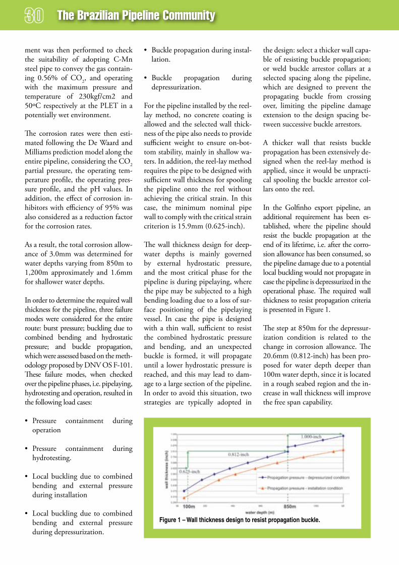
The Brazilian Pipeline Community
ment was then performed to check the suitability of adopting C-Mn steel pipe to convey the gas contain-ing 0.56% of CO2, and operating with the maximum pressure and temperature of 230kgf/cm2 and 50ºC respectively at the PLET in a potentially wet environment.
The corrosion rates were then esti-mated following the De Waard and Milliams prediction model along the entire pipeline, considering the CO2 partial pressure, the operating tem-perature profile, the operating pres-sure profile, and the pH values. In addition, the effect of corrosion in-hibitors with efficiency of 95% was also considered as a reduction factor for the corrosion rates.
As a result, the total corrosion allow-ance of 3.0mm was determined for water depths varying from 850m to 1,200m approximately and 1.6mm for shallower water depths.
In order to determine the required wall thickness for the pipeline, three failure modes were considered for the entire route: burst pressure; buckling due to combined bending and hydrostatic pressure; and buckle propagation, which were assessed based on the meth-odology proposed by DNV OS F-101. These failure modes, when checked over the pipeline phases, i.e. pipelaying, hydrotesting and operation, resulted in the following load cases:
• Pressure containment during operation
• Pressure containment during hydrotesting.
• Local buckling due to combined bending and external pressure during installation
• Local buckling due to combined bending and external pressure during depressurization.
• Buckle propagation during instal-lation.
• Buckle propagation during depressurization.
For the pipeline installed by the reel-lay method, no concrete coating is allowed and the selected wall thick-ness of the pipe also needs to provide sufficient weight to ensure on-bot-tom stability, mainly in shallow wa-ters. In addition, the reel-lay method requires the pipe to be designed with sufficient wall thickness for spooling the pipeline onto the reel without achieving the critical strain. In this case, the minimum nominal pipe wall to comply with the critical strain criterion is 15.9mm (0.625-inch).
The wall thickness design for deep-water depths is mainly governed by external hydrostatic pressure, and the most critical phase for the pipeline is during pipelaying, where the pipe may be subjected to a high bending loading due to a loss of sur-face positioning of the pipelaying vessel. In case the pipe is designed with a thin wall, sufficient to resist the combined hydrostatic pressure and bending, and an unexpected buckle is formed, it will propagate until a lower hydrostatic pressure is reached, and this may lead to dam-age to a large section of the pipeline. In order to avoid this situation, two strategies are typically adopted in
the design: select a thicker wall capa-ble of resisting buckle propagation; or weld buckle arrestor collars at a selected spacing along the pipeline, which are designed to prevent the propagating buckle from crossing over, limiting the pipeline damage extension to the design spacing be-tween successive buckle arrestors.
A thicker wall that resists buckle propagation has been extensively de-signed when the reel-lay method is applied, since it would be unpracti-cal spooling the buckle arrestor col-lars onto the reel.
In the Golfinho export pipeline, an additional requirement has been es-tablished, where the pipeline should resist the buckle propagation at the end of its lifetime, i.e. after the corro-sion allowance has been consumed, so the pipeline damage due to a potential local buckling would not propagate in case the pipeline is depressurized in the operational phase. The required wall thickness to resist propagation criteria is presented in Figure 1.
The step at 850m for the depressur-ization condition is related to the change in corrosion allowance. The 20.6mm (0.812-inch) has been pro-posed for water depth deeper than 100m water depth, since it is located in a rough seabed region and the in-crease in wall thickness will improve the free span capability.
Figure 1 – Wall thickness design to resist propagation buckle.

route selection and structural design for the golfinho gas export Pipeline
It was noted that using an 80-degree pipelaying ramp at 1,200m would require a 1,472kN top tension to lay the 12-inch pipeline designed with 25.4mm (1.000-inch) wall. In order to minimize the top tension during pipelaying in deepwater depths, a con-ceptual design for internal buckle ar-restors was investigated. For this case, a 22.2mm (0.875-inch) pipe would be selected for deepwater, being suf-ficient to resist buckle propagation during installation. This pipe requires a 12-inch pipe with a thicker wall to be butt welded to the pipeline at a given spacing to function as a buckle arrestor. The 31.8mm (1.250-inch) wall thickness was selected based on the DNV OS-F101 recommenda-tions. The internal buckle arrestors could be welded within the stalks in preparation for the spooling to avoid reducing pipelaying speed.
Most of the pipeline route is, howev-er, located in shallow water depths, 50km approximately, where the wall thickness is governed by on-bottom stability as shown in Figure 2.
The assessment of the installation feasibility was performed using the commercial Finite Element Software Offpipe, which is dedicated for pi-pelaying analysis. The analysis was performed by checking the stress levels along the pipe related to the pipelaying geometry for the range of the project water depths.
It is worth emphasizing the follow-ing aspects related to the selection of pipelaying ramp angle:
• Bottom Tension is relevant for the number and size of free spans, and high ramp angles will result in lower bottom tension, conse-quently, allowing for free span optimization.
• A higher ramp angle also requires lower top tension, which is essen-
tial in deepwater depths to keep the required top tension within the vessel capacity.
• Higher ramp angles, however, are limited by the stress levels observed at the sagbend region, mainly in shallow water depths.
route optimization
The pipeline route can now be opti-mized, i.e. re-routed to minimize the number and size of free spans, by as-sessing alternative routes in the an-ticipated rough regions, considering the seabed features observed from the produced geophysical maps. First, the allowable free span needs to be determined, so the number of potential free spans may be esti-mated when assessing the alternative routes.
In the proposed optimized route, the number of free spans higher than 1.0m was reduced to 19, and none is anticipated to be higher than 3m.
final remarks
Little environmental information was available for pipeline design, since the Espírito Santo Basin is a new area of development in deepwater offshore Brazil. A geophysical and oceano-graphic campaign was then put for-ward to provide rationale informa-tion for the pipeline design work.
Geophysical survey has shown that the critical area along the pipeline route was in the shelf break and in deepwater, specifically in water depths ranging from 100 to 350m. The route was optimized and the number and size of free spans was drastically reduced. Due to the pres-ence of canyons, ravines and scarps, the pipelaying in this area should proceed under the lowest values of tension as possible, in order to mini-mize the residual tension along the pipe, maintaining the free spans under the established limits of pipe stress and spans lengths.
The allowable free spans were de-termined based on available local information, which was not in a proper format for vortex induced vibration analysis. The allowable limits were then determined result-ing in preliminary short free spans which should be revised once the oceanographic campaign provides more realistic information for the fatigue analysis.
acknowledgements
The authors would like to thank Petrobras pipeline design and ma-rine installation group for their sup-portive work mainly during the geo-physical and oceanographic survey, and for their comments and sugges-tions kindly presented during the preparation of this paper.
Figure 2 - Required Wall Thickness for On-Bottom Stability.

ePrasheed offers specialized services for the oil and gas industry:• Marketing,MediaManagement,
SupplementsandAdvertising
• TechnicalGhostWritingofcompany,SPEandindustryarticles
• TechnicalTranslationofcompanybrochures,productinformation,technicaldata,instructionmanualsand field applications
• InEnglish,Portuguese,Arabic,RussianandSpanish
Trinidad48-50 Sackville St, Port of SpainTlf: + 1 868 630 7443
London11 Murray St, Camden, NW1 3RETlf + 44 17 53 57 22 57
BrazilAv. Prado Junior, 48 Sala 210 Copacabana Rio de Janeiro - Tlf: + 55 21 22 75 44 92
Supplements
Technical Translations
Engineeringmarketing Communications
increase sales
Brochures
Technical Articlessave Time
Communicate with oil and gas Companies