the brazilian time and frequency atomic standards programjke1/atomic_clocks/... · the ground state...
TRANSCRIPT

The Brazilian Time and Frequency Atomic Standards Program
Mushtaq Ahmed,∗ Daniel Varela Magalhaes, Aida Bebeachibuli, Stella Torres Muller, Renato Ferracini Alves,
Tiago Almeida Ortega, John Weiner,† and Vanderlei Salvador Bagnato
Instituto de Fısica de Sao Carlos, Universidade de Sao Paulo
Caixa Postal 369, CEP 13560-970, Sao Carlos SP Brasil‡
(Dated: June 28, 2007)
Cesium atomic beam clocks have been the workhorse for many demanding applications in science
and technology for the past four decades. Tests of the fundamental laws of physics and the search
for minute changes in fundamental constants, the synchronization of telecommunication networks,
and realization of the satellite-based global positioning system would not be possible without
atomic clocks. The adoption of optical cooling and trapping techniques, has produced a major
advance in atomic clock precision. Cold-atom fountain and compact cold-atom clocks have also
been developed. Measurement precision of a few parts in 1015 has been demonstrated for a cold-
atom fountain clock. We present here an overview of the Brazilian time and frequency metrology
program based on cesium atoms. This activity consists of construction and characterization of
atomic-beam, and several variations of cold-atom clocks. We discuss the basic working principles,
construction, evaluation, and important applications of atomic clocks in the Brazilian program.
Keywords: atomic clock, cold atoms, time and frequency, metrology
I. INTRODUCTION
Precise measurement of time and frequency has great importance in commercial and defense applications as well as infundamental physics. Each atom or molecule absorbs and emits electromagnetic radiation at characteristic transitionfrequencies. Some of these frequencies lend themselves to stabilization over time and space and therefore constitutenatural frequency standards. The U.S. National Institute for Standard and Technology (NIST) built up its firstfrequency standard clock based upon an ammonia transition in 1949 (Lyons 1949). The ammonia clock performance,however, was not better than conventional clocks existing at that time. The National Physical Laboratory (NPL) inEngland built up the first practical cesium atomic clock in 1955 (Essen and Parry 1957), and in 1967 atomic clocktechnology enabled scientists to define the unit of time, the second, based on atomic measurements (CGPM 1967).
In current primary atomic frequency standards, transitions between ground state hyperfine energy levels in cesiumatoms at microwave frequencies form the basis for measuring time. The present definition is: The second is the
duration of 9 192 631 770 periods of the radiation corresponding to the transition between the two hyperfine levels ofthe ground state of the cesium 133 atom at a temperature of 0 K.
1 second = 9 192 631 770 periods of the Cs133, F = 3, mF = 0 ↔ F = 4, mF = 0 hyperfine transition
The usual stability (precision) of Cs atomic beam clocks is a few parts in 1013, and the uncertainty (accuracy) isof the order of one part in 1014. For the modern cold-atom fountain clock two orders of improvement in stabilityis possible and about one order in uncertainty. Atomic clocks use natural internal-state transitions within atoms ormolecules to keep time. These quantum mechanical oscillators are vastly less sensitive to gross environmental effectssuch as temperature, pressure, humidity, and vibration, for example, than macroscopic oscillators such as pendulumsand quartz crystals. But the most important advantage of atomic clocks is that every atom of a given element andisotope is identical. Therefore an atomic clock standard based on Cs133 transitions is transferable the world over. Theatomic clock is the most stable and accurate clock known. Atomic clocks are so good that time and frequency canbe measured more precisely than any other physical quantity. Cesium atomic clocks are the primary standard, andrubidium clocks are accepted as a secondary standard.
Modern life depends upon the precise time. Communication, financial transactions, electric power and many otheractivities have become dependent upon time accuracy. The demand of these technologies will continue to drive
∗Permanent Address: Optics Laboratories, PO Box 1021, Islamabad, Pakistan†Permanent Address: Universite Paul Sabatier, Toulouse, France‡Electronic address: [email protected]

2
research toward more accurate, precise, and transferable time standards. Improvement in the development of thefrequency and time standard is continually in progress. Development of the harmonic generating “frequency comb”made the optical frequency regime a prominent candidate for an advanced frequency standard. Cold atoms and coldions are certainly the most promising systems for the development of a new atomic standard (Bize et al. 2005, Ma etal. 2004, Udem et al. 2002). Any country which aspires to develop and grow technologically must include a seriousprogram of scientific time and frequency metrology.
In this paper we provide an overview of the scientific time and frequency program at University of Sao Paulo in SaoCarlos. The program is composed of different types of atomic clocks based on cesium atoms. Historically the earth’srotation was used as a time standard, and we start by discussing how this standard relates to the atomic standard.We then discuss briefly some of the current applications for atomic clocks followed by a more detailed description ofclocks constructed and under development at USP Sao Carlos.
II. SYSTEMS OF TIME: UTC AND TAI
Originally, the local time at the Royal Observatory, Greenwich, England was chosen as standard at the 1884International Meridian Conference, leading to the widespread use of Greenwich Mean Time (GMT) in order to setlocal clocks. This location was chosen because by 1884 two-thirds of all charts and maps already used it as their PrimeMeridian. In 1929, the term Universal Time (UT) was introduced to refer to GMT with the day starting at midnight.Until the 1950s, broadcast time signals were based on UT, and hence on the rotation of the Earth. CoordinatedUniversal Time (UTC), a high-precision atomic time standard, is an updated variant of UT. As a time scale, UTCdivides up time into days, hours, minutes, and seconds. Each day contains 24 hours and each hour contains 60 minutes,but the number of seconds in a minute is slightly variable. UTC has uniform seconds defined by International AtomicTime, referred to as TAI from the French “Temps Atomique International”, with leap seconds announced at irregularintervals to compensate for the earth’s slowing rotation and other discrepancies. Leap seconds allow UTC to closelytrack Universal Time (UT), based on the Earth’s angular rotation. UTC is derived from TAI, which tracks propertime from atomic standards with no reference to the rotation of the Earth. At any particular time, UTC proceeds asa linear function of TAI, and since 1972 UTC “ticks” at the same rate as TAI. UTC occasionally has discontinuitieswhere it changes from one linear function of TAI to another. These discontinuities take the form of leaps implementedby a UTC day of irregular length. The accuracy and stability of atomic clocks is the effective standard for TAI.Atomic clocks maintain a continuous and stable time scale for TAI, and provide an excellent reference for time andfrequency in scientific applications. The UTC, not the TAI, is the time distributed by standard radio stations thatbroadcast time, such as WWV and WWVH. It can also be obtained readily from the GPS satellites (Audoin andGuinot 2001, Nelson et al. 2001, Riehle 2004, Jesperson and Fitz-Randolph 1999).
III. APPLICATIONS OF ATOMIC STANDARDS
The precise and accurate measurement of time and frequency plays a fundamental and important role in thesuccess of many fields of technologies and research. Atomic clock technology has several practical applications. Onthe scientific side, atomic clocks provide a sensitive probe for minute variations in physical constants such as the finestructure constant, α. Clocks can also be used to search for variations in the isotropy of space, preferred frames ofreference, charge- parity-time (CPT) symmetry violation and to test the theories of relativity and electrodynamics(Uzan 2003). Precise and accurate clocks may provide the means to revel new phenomena signaling a fundamentalchange in how we perceive nature (Riehle 2004, Audoin and Guinot 2001). Practical applications include metrology,geodesy, global positioning systems for navigation, communication, electric power networks and defense. We shallbriefly discuss these practical applications as well.
A. Fundamental Physics Research
According to Einstein’s Equivalence Principle (Vessot and Levine 1979), fundamental constants should not varywith time, but some modern theories predict the existence of variation. The development of atomic clocks (Cs andRb) have provided the accuracy necessary to test fundamental constants like the Rydberg constant R and the finestructure constant α and their possible slow variation with respect to time. Recently a stringent upper limit has beenset to a possible fractional time variation of the ratio of hyperfine transition frequencies in Rb and Cs atoms.
d
dtln
[
νRb
νCs
]
=
(
µRb
µCs
)
α−0.44 = (0.2 ± 7.0) × 10−16 year−1 (1)

3
where µRb and µCs are the magnetic moments of rubidium and cesium respectively. Furthermore it can be shownthat the sensitivity of the ratio of νRb/νCs to a variation of α is given by
∂
∂ lnαln
(
νRb
νCs
)
≃ −0.44 (2)
Combining Eqs. 1 and 2, the upper limit to the fractional time variation of the fine structure constant is
α
α= (−0.4 ± 16) × 10−16 yr−1 (3)
(Marion et al. 2003). In another approach (Peik et al. 2004) measured an optical transition frequency in the Yb+
ion over a period of almost three years and were able to relate the constancy of this frequency to an upper limit onthe variability of α of 2.0 × 10⁻¹⁵ yr−1. The advantage of this approach is that it is independent of the assumedconstancy of the atomic masses or magnetic moments.
Precise atomic spectroscopy, precision interferometry for gravitational wave detection, and other astrophysicalmeasurements as well as tests for relativity, quantum electrodynamics and CPT invariance can be made possibleusing ultra-stable atomic clocks (Bize et al. 2005, Flambaum 2006, Uzan 2003, Vessot et al. 1980).
In 1993 the quantity gp(me/mp) was measured by comparing the frequency data of Cs and Mg atomic beamstandards (Godone et al. 1993), where gp is the proton gyromagnetic ratio and me, mp are the mass of the electronand proton respectively. The time stability of this quantity is an important subject for theoretical physics as well asfor dimensional metrology. The study of time variation of such quantities or its product with fine structure constantplays an important role in definition of international standards (SI).
We list here a few specific examples of important applications in time and frequency measurements.
1. Time dilation test
U.S Naval Observatory performed an experiment to test time dilation in 1971, (Hafele and Keating 1972). Airlineflights around the world in opposite directions carried four Cs atomic beam clocks. At the end of the flights it wasfound that the traveling clocks gained about 0.15 µs relative to rest clocks. Measurement of time dilation has beenan important test for special relativity.
2. Pulsar frequency detection
Atomic clocks were used to monitor the frequency variation of pulsars. Repeated radio pulses from stars in our galaxywere discovered in 1960. These pulses called “pulsars” were attributed to rotating neutron stars which emit lighthouse-type sweeping beams as they rotate (Ramsey 1990). The study of such phenomenon advance our understanding ofstar formation and evolution of the universe.
B. Positioning and navigation on the earth surface
Navigation has continued to be one of the principal applications of accurate clocks. Frequency standards provideenabling technology for satellite navigation systems and at the same time satellite systems distribute time and fre-quency standards to the whole world. The Global Positioning System (GPS) originally consisted of 24 satellites,placed in the earth orbit in 1989. The GPS constellation of satellites has been continuously updated since the firstlaunch in 1989 of the Block II satellite. Presently with the last launch of Block IIR-M in 2006, it operates with 30satellites distributed in four categories (Block II, IIA, IIR, and IIR-M). Atomic clocks can be found in all 30 of thesatellites. These clocks, together with ground based clocks, enable sailors, pilots, drivers and hikers to know theirlocation on the earth surface within a few meters. Planes navigate using GPS although it is not yet acceptable toland an aircraft by GPS alone since atomic clocks on satellites are still not accurate enough and it takes too long tocompute positions. These atomic clocks are periodically updated from the ground primary Cs clock at the U. S. NavalObservatory. These satellites transmit both timing and positioning data. The combination of primary frequency stan-dard (Cs atomic clock) and commercial atomic standards (Cs and Rb clocks) and a stable communication networkprovide accurate time and frequency. The GPS provides altitude, latitude and longitude with an uncertainty of lessthan 10 meters. Improvement in the ground-based master clocks that calibrate the GPS atomic clocks along withbetter satellite clocks will allow transportation systems to locate vehicles with sub-meter precision in real time. It isnot only the GPS space system that carries atomic clocks on board. The Russian navigation satellite system, Glonass,

4
is also similarly equipped. Initially implemented in the Soviet Union, this system fell into disrepair, but with the helpof the Indian government it is now being restored. Other proposed systems are in development such as COMPASS(China), GALILEO (European Union), and an updated version of GPS called GPS III that is planned to be fullyoperational in 2013. Communication satellite systems such as Milstar require the robust timekeeping capabilities ofatomic clocks in order to provide secure communications. As the competition for radio frequency bandwidth increases,other communication systems, commercial as well as military, may have to rely on atomic clocks to provide accuratefrequency and time on board spacecraft. Satellite ranging for deep space will require an accuracy of 1015 to 1017,(Allan et al. 1994, Audoin and Guinot 2001, Bauch 2003, McCaskill et al. 1999, Riehle 2004 , Wu and Feess 2000).
C. Space Geodesy
Time and frequency standards have enabled space-based geodesy systems to acquire high accuracy for importantinvestigations of earth including open ocean circulation, sea level monitoring, and the measurement of man-madegaseous emissions. Atomic clocks in satellites are important to satellite laser ranging (SLR) and the hydrogen maserreference used in very long baseline interferometry (VLBI). Without the development of these atomic clocks theseinstrumental techniques would not be possible (Shapiro et al. 2003). The TOPEX/POSEIDON project was initiatedto monitor global oceans circulation by satellite. Satellite observations of the oceans are important because theyprovide long-term, continuous measurements sea surface height, sea surface temperature and other climate conditionsover the entire earth. Accuracy of these measurements depends upon the atomic clocks launched in satellites (Cazenaveet al. 1997).
D. Length and other physical properties measured as frequency
Presently there exists no other quantity measured as precisely as frequency. Due to this unique capability, it ispossible to measure more precisely other physical quantities using frequency and time. Considerable efforts are underway to translate the measurement of length, speed, temperature, electric field, magnetic field, voltage, etc. intofrequency. The meter (m) is the Systeme International (SI) unit of length and is now defined as the length of thepath traveled by light in vacuum during the time interval of 1/299 792 458 of a second, i.e. 1/c. This new definitionreplaces two previous definitions of the meter: the original adopted in 1889 based on a platinum-iridium prototype bar,and a definition adopted in 1960 based on a krypton86 radiation from an electrical discharge lamp. The krypton86electrical discharge lamp was designed to produce the Doppler-broadened wavelength of the 2p105d5 transition of theunperturbed atom. The two dominant wavelength shifts, one caused by the DC Stark effect and the other by the gaspressure in the discharge lamp, were opposite in sign and could be made equal in magnitude by the proper choice ofoperating conditions. Different krypton86 lamps reproduced the same wavelength to about 4 parts in 109, but had thedisadvantage that the coherence length of its radiation was shorter than the meter, complicating the changeover fromthe older standard. Faced with the possibility that further advances in laser spectroscopy would lead to proposalsfor new length standards based on more precise atoms or molecules, a new concept for the length standard definitionwas developed. The second (which is equivalent to 9,129,631,770 oscillations of the cesium-133 microwave transition)and the meter are now considered independent base units. Traditionally, the speed of light was measured in termsof their ratio. By contrast, the present standard defines the meter in terms of the SI second and a defined value forthe speed of light in vacuum which fixes it to 299 792 458 m s1 exactly. Thus the meter is determined experimentallybased on the cesium-133 frequency standard. Since it is not based on a particular radiation, this definition opensthe way to major improvements in the precision with which the meter can be realized using laser techniques withoutredefining the length standard. As a practical matter the meter can be measured at different, more convenient opticalfrequencies and referenced back to the cesium-133 standard using frequency chains (Udem 2002, Schnatz 2003)
E. Time synchronization of computers
The discussion in the section is taken from the Wikipedia entry on the Network Time Protocol. The Network TimeProtocol (NTP) is a protocol for synchronizing the clocks of computer systems over packet-switched, variable-latencydata networks. NTP uses an algorithm with the UTC time scale, including support for features such as leap seconds.NTP v4 can usually maintain time to within 10 milliseconds (1/100 s) over the public Internet, and can achieveaccuracies of 200 microseconds (1/5000 s) or better in local area networks under ideal conditions. Atomic clocks areused to synchronize computer clocks. NTP uses a hierarchical system of ”clock strata”. The stratum levels define thedistance from the reference clock and the associated accuracy.
5
1. Stratum 0
These are devices such as atomic (cesium, rubidium) clocks, GPS clocks or other radio clocks. Stratum-0 devicesare not attached to the network; instead they are locally connected to computers.
2. Stratum 1
These are computers attached to Stratum 0 devices. Normally they act as servers for timing requests from Stratum2 servers via NTP. These computers are also referred to as time servers. Many Stratum 1 servers (for NTP v3 andearlier versions) may not actually be operating with Stratum 1 precision. As the NTP protocol is developed, it willbecome less and less possible for misleading Stratum 1 servers to run – instead the protocol would automaticallybump the server Stratum level down to an appropriate level.
3. Stratum 2
These are computers that send NTP requests to Stratum 1 servers. Normally a Stratum 2 computer will referencea number of Stratum 1 servers and use the NTP algorithm to gather the best data sample, dropping any Stratum 1servers that seem obviously wrong. Stratum 2 computers will peer with other Stratum 2 computers to provide morestable and robust time for all devices in the peer group. Stratum 2 computers normally act as servers for Stratum 3NTP requests.
4. Stratum 3
These computers employ exactly the same NTP functions of peering and data sampling as Stratum 2, and canthemselves act as servers for higher strata, potentially up to 16 levels. NTP (depending on what version of NTPprotocol in use) supports up to 256 strata. It is hoped that in NTP 5 (a protocol still in development) that only 8 or16 strata will be permitted.
F. Defense
Frequency standards and clocks play a major role in military communication, navigation, surveillance, missileguidance, Identification Friend or Foe (IFF) and Electronic Warfare (EW) systems. The major enabling technologiesrequire robustness to environmental disturbances, low input power, long stability, high accuracy, small size and weight.Development of more compact atomic clocks will better meet these requirements. The mobility and robustness ofmilitary systems and platforms can be improved by using ultra-miniature time reference units such as chip-scale atomicclocks. The ultra-stable frequency reference provided by atomic clocks will drastically improve channel selectivity anddensity for all military communications.
IV. IMPLEMENTATION OF ATOMIC FREQUENCY STANDARDS
Atomic frequency standard can be either active or passive. An active atomic standard uses the electromagneticradiation emitted by atoms themselves as they decay from a higher energy state to a lower energy state. A passivestandard matches the frequency of an electronic oscillator or laser to the resonant frequency of the atoms by meansof a feedback circuit.
There are different types of atomic clocks, but they are all based on an equivalent basic principle. The differencesare the type of atom and detection mechanism. There are three most common types of atomic clocks in use. Theseare based on the cesium, rubidium and hydrogen atoms. Figure 1 illustrates the working principle of an atomic clock.The oscillatory mechanism of the clock is the atom itself. Atomic energy states and hence the transition frequencyν0 = (E2 − E1) /h between them serves as a basis for the clock operation. This transition frequency is intrinsicallyindependent of space and time. When an electronic transition takes place in the atom between two energy levels, iteither emits or absorbs an electromagnetic (EM) wave with a center frequency ν0. All the atoms of the same elementand isotope absorb or emit electromagnetic radiation of the same frequency. This is the fundamental difference ofatomic clocks as compared to other time-keeping devices. The microwave oscillator provides the frequency for theatomic transition which, through the atoms, is corrected until the difference between the frequency of the oscillator

6
FIG. 1 Schematic diagram showing the working principle of the atomic clock.
and the atoms is minimized. The oscillator is then locked to this transition using a feed back loop. The choice of aspecific frequency of a selected atom depends on certain requirements to acquire best accuracy and stability. To obtainhigh precision, the natural line width of the transition should be as small as possible and the interaction time betweenthe atomic and radiation should be as long as possible. This characteristic implies a high quality factor Q = ν0/∆ν0
for the atomic transition. Signal to noise ratio (S/N) of the observed resonance transition should be large to minimizestatistical fluctuations of the signal controlling the local oscillator (LO). The velocity of the atoms should be low tominimize Doppler shifts. The resonance atomic transition should be insensitive to electric and magnetic fields and topressure broadening effects.
How to measure the clock transition with minimum external influence?An ingenious answer to this key question is the idea of Ramsey (Ramsey 1950) known as the two- separated-zones
interaction in an atomic beam. In this method, when the atom beam travels down an evacuated tube, the atomsinteract with two separated microwave cavities. The probability that an atomic transition in the first and in thesecond zone occurs depends upon a number of parameters.
A. Ramsey Method
In the Ramsey method, atoms in the beam pass through two separated zones of length l having two phase-coherentmicrowave fields that are spatially separated by the distance L, where L >> l. The characteristic signature of theoutput of an atomic clock is the Ramsey fringe pattern. The Ramsey fringes trace the transition probability betweenthe two atomic states as a function of microwave frequency as the atoms move in two separated microwave interactionzones as shown in Fig. 2. The fringes originate from an interference of transition couplings that comes from bothinteraction zones. With this approach the basic goal is to reduce the transit-time broadening arising from the finitetime that the atoms spend within each of the interaction zones. To understand how the Ramsey technique reducesthe line width of a transition, consider a two-level atom with states |0〉 and |1〉 . At time t = 0, this atom enters amicrowave region of length l, where it is perturbed by an oscillatory microwave electromagnetic field and as a resultan atomic excitation takes place. The probability P of transition between the two states |0〉 and |1〉 is given by thefollowing equation.
P (τ) =b2
Ω2sin2
(
Ωτ
2
)
with
Ω =[
(ω0 − ω)2
+ b2]1/2
and b =µB
~B
Here τ is the interaction time within the zone l, ω0 is the atomic transition frequency, ω is the applied microwavefrequency, µB is the Bohr magneton, B is the amplitude of the microwave magnetic field and ~ is Planck’s constantdivided by 2π. The quantity b is a measure of the strength of the magnetic dipole coupling between the magneticcomponent of the microwave field and the atom. It is known as the Rabi frequency (Ramsey 1990). The first factoron the right hand side of the expression for P (τ) becomes unity when ω =ω0 (resonance) and the full width at halfmaximum is ∆ω = 5.02/τ . The second factor is time-dependent. The probability will be maximum at ω =ω0, whenbτ = π. The interaction time is τ = l/υ where υ is the velocity of the atomic beam and l is the length of interactionregion. The width for such a transition under these conditions can be expressed as ∆ω = 5.02/τ = 5.02υ/l.
7
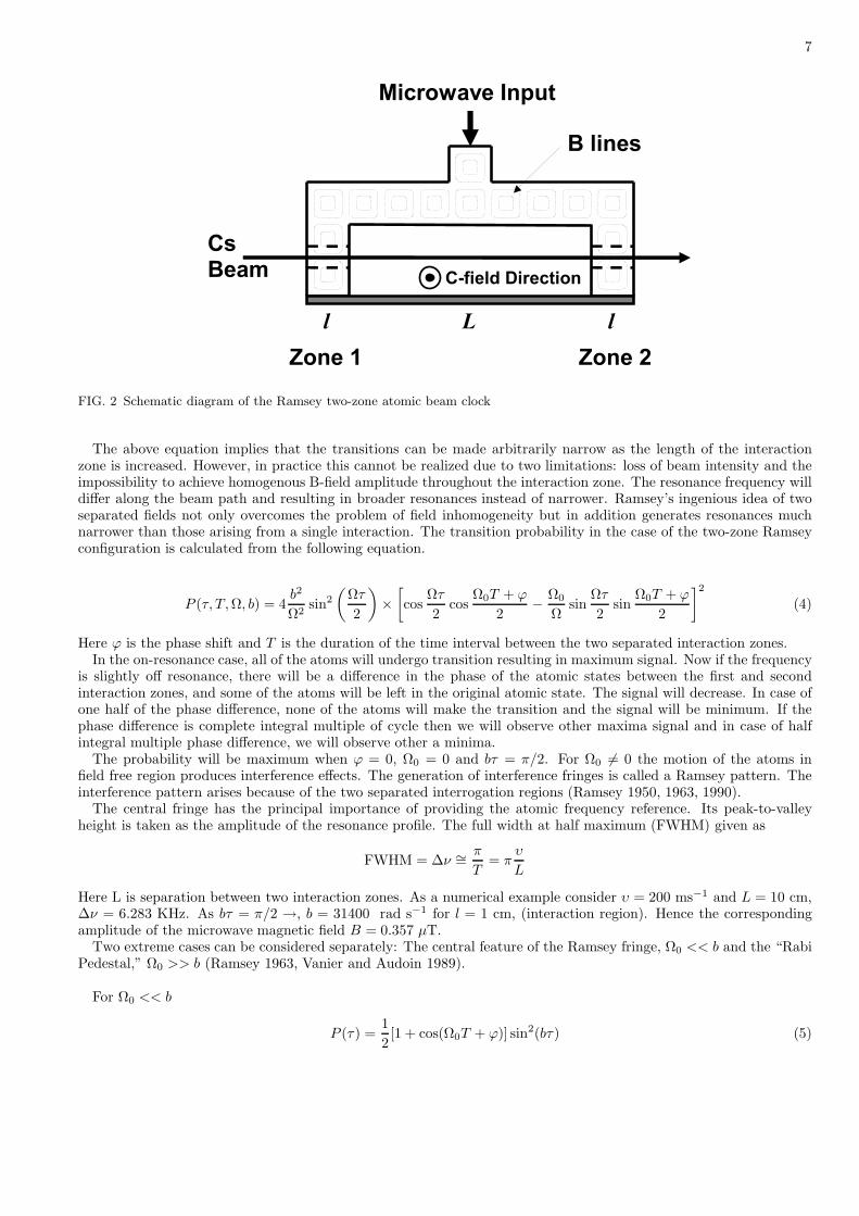
FIG. 2 Schematic diagram of the Ramsey two-zone atomic beam clock
The above equation implies that the transitions can be made arbitrarily narrow as the length of the interactionzone is increased. However, in practice this cannot be realized due to two limitations: loss of beam intensity and theimpossibility to achieve homogenous B-field amplitude throughout the interaction zone. The resonance frequency willdiffer along the beam path and resulting in broader resonances instead of narrower. Ramsey’s ingenious idea of twoseparated fields not only overcomes the problem of field inhomogeneity but in addition generates resonances muchnarrower than those arising from a single interaction. The transition probability in the case of the two-zone Ramseyconfiguration is calculated from the following equation.
P (τ, T, Ω, b) = 4b2
Ω2sin2
(
Ωτ
2
)
×
[
cosΩτ
2cos
Ω0T + ϕ
2−
Ω0
Ωsin
Ωτ
2sin
Ω0T + ϕ
2
]2
(4)
Here ϕ is the phase shift and T is the duration of the time interval between the two separated interaction zones.In the on-resonance case, all of the atoms will undergo transition resulting in maximum signal. Now if the frequency
is slightly off resonance, there will be a difference in the phase of the atomic states between the first and secondinteraction zones, and some of the atoms will be left in the original atomic state. The signal will decrease. In case ofone half of the phase difference, none of the atoms will make the transition and the signal will be minimum. If thephase difference is complete integral multiple of cycle then we will observe other maxima signal and in case of halfintegral multiple phase difference, we will observe other a minima.
The probability will be maximum when ϕ = 0, Ω0 = 0 and bτ = π/2. For Ω0 6= 0 the motion of the atoms infield free region produces interference effects. The generation of interference fringes is called a Ramsey pattern. Theinterference pattern arises because of the two separated interrogation regions (Ramsey 1950, 1963, 1990).
The central fringe has the principal importance of providing the atomic frequency reference. Its peak-to-valleyheight is taken as the amplitude of the resonance profile. The full width at half maximum (FWHM) given as
FWHM = ∆ν ∼=π
T= π
υ
L
Here L is separation between two interaction zones. As a numerical example consider υ = 200 ms−1 and L = 10 cm,∆ν = 6.283 KHz. As bτ = π/2 →, b = 31400 rad s−1 for l = 1 cm, (interaction region). Hence the correspondingamplitude of the microwave magnetic field B = 0.357 µT.
Two extreme cases can be considered separately: The central feature of the Ramsey fringe, Ω0 << b and the “RabiPedestal,” Ω0 >> b (Ramsey 1963, Vanier and Audoin 1989).
For Ω0 << b
P (τ) =1
2[1 + cos(Ω0T + ϕ)] sin2(bτ) (5)

8
FIG. 3 Ramsey interference pattern showing central fringe andbroad Rabi pedestal.
FIG. 4 The seven Zeeman sublevel transitions possible for the6S1/2 (F=3)→ 6S1/2 (F =4); ∆mF = 0.
For Ω0 >> b
P (τ) =1
2
b2
Ω2
sin2(Ωτ) +
[
Ω0
Ω(1 − cos(Ωτ))
]2
Figure 3 illustrates the recorded signal of the Ramsey central fringe and Fig. 4 all seven possible Zeeman transitions6S1/2 (F=3)→ 6S1/2 (F =4); ∆mF = 0. The signal consists of a narrow spectral feature (Ramsey central fringe)superimposed on the broader envelope(Rabi pedestal). The Rabi pedestal is related to the transit time broadeningas the atoms pass through the two microwave regions as well as the velocity distribution of the atoms in the thermalbeam. This pedestal is much more significant for the atomic-beam frequency standard (20 kHz) than for the atomicfountain (cf. Section VI) using optically cooled atoms (70 Hz). The overall shape of the Rabi pedestal is due to thecombined effects of the probability that a transition occurs in the first excitation region but not in the second, plusthe probability that it occurs in the second excitation zone but not in the first.
Characteristic parameters such as Rabi frequency, second order Zeeman effect, second-order Doppler shift, and theend-to-end cavity phase shift were quantitatively analyzed. These characteristic parametric measurements are veryimportant to correct the clock frequency, and will be addressed in the next section.
V. CESIUM BEAM ATOMIC CLOCK
The cesium atom has proved to be a good choice for the development of a clock. Three kinds of cesium clocks areunder development in Brazil. These are the cesium atomic beam, the cesium fountain and the cesium “expandingcold atoms” clock. All of these cesium-based atomic clocks have been constructed and evaluated at the University ofSao Paulo at Sao Carlos.
The Cs133 atom is a stable element. It is highly electropositive and reactive. The saturating Cs vapor pressureat room temperature and at 100 C is 1.86 × 10⁻⁴ and 7.45 × 10⁻² Pa, respectively. Cesium has only one valenceelectron and a 2S1/2 ground-state Russell-Saunders term. The nuclear magnetic spin of Cs133 is 7/2. The ground-state term is split into two hyperfine levels, F = 3 and F = 4. At room temperature, the two hyperfine levels arepopulated according to their 2F + 1 degeneracies. Figure 5 illustrates the relevant term energy diagram of Cs133.The energy of the Zeeman sublevels, labeled mF , is proportional to the applied magnetic field and is expressed inunits of kHz/G. In the absence of an external magnetic field, the mF Zeeman sublevels are degenerate. The clocktransition between between states F = 3, mF = 0 to F = 4, mF = 0 is a magnetic dipole transition. The probabilityof spontaneous magnetic dipole relaxation from the upper hyperfine state is very low, and therefore atoms in theexcited state F = 4, mF = 0 will remain there for a very long time compared to the observation time.

9
FIG. 5 Diagram of the internal levels and transitions relevant to the Cs atomic beam clock
A. Construction of the cesium atomic beam clock
The Brazilian Cs atomic beam clock was designed and developed following the scheme of the Ramsey two-separated-microwave- interaction zones. The basic advantage of this experimental scheme is the reduction of time-of-flightbroadening and increase of the atoms number that participates during the interrogation and detection process. Thenatural line width of radio frequency and microwave transitions is extremely small because the spontaneous transitionprobability is proportional to the frequency cubed. Therefore, the spectral line width of these transitions is determinedby transit-time broadening ∆ν = 1/T = υ/L. The term T is the atom time of flight between two microwave interactionzones, υ is the velocity of the atoms and L is the length between two interaction zones.
B. Cesium atomic beam apparatus
The cesium beam apparatus consists of a stainless steel cylindrical chamber with diameter 20 cm and length 90 cm,Cs oven, microwave cavity, C-field, graphite beam-collimating discs, vacuum pump and optical detection. There are10 ports on the chamber. Four laser beam ports, one vacuum port, one for the microwave source, two for electricalfeeds and two for Cs beam input and output. A schematic view of the Cs beam apparatus is shown in Fig. 6. A turbomolecular pump was used to maintain the background pressure at less 10−5 Pa. The cesium oven was operated at100 C. The beam divergence less than 200µsteradians was obtained using a number of collimating stainless steel andgraphite discs having a 2 mm hole diameter. Graphite discs were used to adsorb residual Cs atoms scattered out ofthe main beam. The C-field is produced by using four coils as illustrated in Fig. 6. This configuration produces amagnetic field perpendicular to the atomic beam and is used to lift the degeneracy of the hyperfine sublevels mF ofthe Cs ground state. The U-shaped copper microwave cavity consists of two interrogation zones, each having 10 mmlength and 5 mm width. The separation between the two zones is 90 mm. The atoms in the two zones interact withmicrowaves generated by the microwave synthesizer. The quality factor Q(= ν/∆ν) of the cavity is about 500 atthe oscillation frequency of 9.2 GHz. The whole microwave cavity region is shielded with µmetal to avoid externalmagnetic field perturbations.
The Cs atoms are prepared in a selected ground state hyperfine level and detected using laser induced fluorescence

10
FIG. 6 Schematic diagram of the Cs atomic beam clock
before and after the microwave cavity region using a stabilized diode laser (Teles et al. 2000).
1. Microwave synthesizer, control and comparison
The microwave synthesizer (HR1 ♯003) used to interrogate the Cs atoms was built in NIST (National Instituteof Standards and Technology - Bolder - USA), by Dr. F. Walls team (Sen Gupta A. et al. 2001). Depicted inFig. 7, it is constituted of three base high performance quartz oscillators (5 MHz, 100 MHz and 10.7 MHz WenzellVCXO’s). Phase Locked Loops (Phase Detectors and Loops Filters) are implemented in order to extract the bestspectral characteristics of each oscillator and synthesize the 9.192 GHz interrogation signal. An external DDS (DirectDigital Synthesizer - SR345 Stanford), driven in external reference by the 5 MHz oscillator, provides the capability tosweep the microwave signal. Once phase locked to the 5 MHz oscillator, the 100 MHz signal is multiplied by a factorof five. The 500 MHz signal is then mixed to the signal from the 10.7 MHz oscillator and feeds a Step Recovery Diode(SRD). This device, based on a nonlinear effect, generates a frequency comb with the harmonics of the 510.7 MHzinput signal. With proper filtering, only the 18th harmonic of 510.7 MHz is obtained, producing 9.1926 GHz. The10.7 MHz oscillator is phase locked to the external DDS, in order to provide a fine-tuning capability in the microwavesignal. A LabVIEW computer interface program controls the DDS. The synthesizer has the frequency resolution of18 × 10−6 Hz and fractional frequency stability better than 3 × 10⁻¹⁴τ−1/2 for 104 seconds of averaging time.
2. Optical pumping and detection
Initially, for the development of cesium atomic clocks, the magnetic state selection and detection of ground statehyperfine levels using a Stern-Gerlach technique was implemented successfully by a number of workers (Bauch 2003,Vanier and Audoin 1988 and references therein). However, optical pumping schemes can be used effectively for stateselection and state detection as well. Optical schemes are more attractive compared to the use of inhomogeneousmultipole magnets (Stern-Gerlach technique) because they avoid stray magnetic fields. Optical schemes have theadvantage of single-state selection efficiency in which all the population can be pumped into a single state. Anexternal cavity-stabilized, single-mode diode laser (SDL 5412-H1) was used for pumping and detection. A conventionalsaturation absorption technique was used to stabilize and reference the laser. Wavelength tuning was achieved byvarying the current and temperature. The line width of the laser after stabilization was less than 500 KHz. Theoptical schematic diagram is shown in Figure 6.
The optical pumping scheme involves the transfer of all the atoms to the 6 2S1/2 (F=3) ground level before the

11
FIG. 7 Schematic diagram of the microwave synthesizer for the beam clock.
atoms enter the microwave cavity and fluorescence detection from the transition 6 2S1/2 (F=4)→ 6 2P3/2 (F =5) afterthe second microwave interaction zone. To stabilize the laser at a certain atomic line, a part of the laser beam wassent to pass through cesium cell. The laser wavelength was locked at the 6 2S1/2 (F=4) −→ 6 2P3/2 (F =5) transitionof the saturation absorption line of the cesium cell to avoid the long term drift. The remaining part of the laser beamwas propagated through the acoustic optical modulator (AOM). The AOM modulator was operated at 250 MHz togenerate first order diffracted and zero order beams for pumping 6 2S1/2 (F=4) −→ 6 2P3/2 (F =4) and detection
6 2S1/2 (F=4) −→ 6 2P3/2 (F =5) respectively (Teles et al. 2000). Optical pumping for the radiative transitions inalkalies takes about 10µ sec .
C. Evaluation of the Cs atomic beam clock
The performance of a time and frequency standards depends on stability, frequency shifts uncertainty and accuracy.The stability criterion can be divided into short and long term stability, both of which are evaluated by the “Allanvariance.” The frequency shift of true hyperfine transitions can occur due to a number of external and internalperturbations such as black body transitions, Gravitational field, and Doppler and Zeeman effects. These effectsmanifest themselves as frequency offsets.
Before presenting the clock evaluation, it is worthwhile to introduce the concepts of accuracy, stability, and repro-ducibility. They are often used to describe an atomic clock quality with respect to its instabilities.
Accuracy is the degree of correctness of a quantity with respect to the true value. It is related to the offset froman ideal value. In the world of time and frequency, accuracy is used to refer to the time offset or frequency offset ofa device from the value of the international primary standard.
Stability is the inherent characteristic of a device that determines how well it can produce the same value over agiven time interval. Stability does not determine whether the frequency of a clock is right or wrong, but only whetherit stays the same. The stability of an oscillator does not necessarily change when the frequency offset changes. Onecan adjust the frequency of an oscillator by moving either further away from or closer to its nominal frequency withoutchanging its stability.
Reproducibility is the ability of a device to produce the same value, without any adjustment, each time when it isoperated.

12
D. Evaluation of the frequency stability and Allan variance
The frequency stability of an oscillator is the degree to which it maintains the same value throughout the specifiedtime interval. The short-term stability of a well designed beam clock is limited by shot-noise and abrupt changes,whereas long-term stability is limited by changes in the magnetic field environment, velocity distribution changes,cavity temperature change, microwave level change, and other environmental perturbations. The stability is charac-terized by the “Allan variance” (Allan 1966,1989). It is defined as one half of the time average of the squares of thedifferences between consecutive measurements. The Allan variance is expressed as:
σ2y(τ) =
1
2
⟨
(yn+1 − yn)2⟩
(6)
where yn is the fractional frequency error, averaged over sampling period τ . The normalized frequency is defined as:
yn =
⟨
δν
ν
⟩
n
where ν is the reference clock frequency and δν is the error in frequency, and the average is performed over n samplingperiods. The division by two in Eq. 6 causes this variance to be equal to the classical variance if the y’s are taken froma random and uncorrelated function, i.e. white noise. The advantage of this variance over the classical variance isthat it converges for most of the commonly encountered kinds of noise, whereas the classical variance does not alwaysconverge to a finite value. Flicker noise and random walk noise are two examples that commonly occur in macroscopicoscillators where the classical variance does not converge. Allan variance is used as to measure the stability of anumber of precision oscillators such as atomic clocks and frequency-stabilized lasers. The stability of the atomic clockis given by the square root of the Allan variance and can be defined as:
σ(τ) =
[
πQatS
N
]−1 [
t
τ
]1
2
where τ is the sampling time, Qat is the quality factor of the atomic resonance, S/N is the signal to noise ratio for asampling time τ and t is the cycle time. If we plot the values of square root of Allan variance σ(τ) as a function ofsampling time τ on a log-log scale then the slope will characterize the type of noise in the clock. For the Brazilianatomic beam clock, the short-term stability was determined using a commercial atomic standard (Agilent - 5071A) anda computer with a GPIB interface to store the data reading, allowing us to perform a constant evaluation of the atomicbeam standard. Figure 8 shows the measured values of σ of our Cs133 beam frequency standard versus the samplingtime τ . For the present evaluation, the short term stability of the Cs clock is σ(τ) = 6.6 ± 0.2)× 10−10 τ−0.50+0.1.
E. Frequency shifts and uncertainties
The frequency of the clock transition is affected by a number of small frequency offsets due to external as wellas internal sources. As a result measured frequency differs from the actual value. By definition, the frequency of aclock transition must be determined in the absence of these perturbations. Therefore, the frequency shifts due toperturbation must be estimated, and the measured frequency value be adjusted accordingly. These shifts includerelativistic effects, interaction due to external electric and magnetic fields, losses and changes in microwave cavity,effect of neighboring transitions and instrumental drift. Each of these are discussed below:
1. Determination of the Rabi frequency
From the Ramsey fringes one can obtain important operation parameters. The transition rate for the Ramseyinterrogation depends on the Rabi frequency. The Rabi frequency is written as, b = µB/~B, where B is the microwavemagnetic field amplitude in the interrogation region and can be determined by measuring the power of the microwavesignal injected into the cavity. The method that we have used makes it easier to ascertain the Rabi frequency by amathematical analysis of the experimental Ramsey pattern. This analysis provides greater accuracy of the Ramseypattern (Makdissi and de Clerq 1997). In order to obtain better precision in the determination of the Rabi frequency,we take the second derivative of 5 and rewrite it as a sum of three Dirac pulses at different frequencies (Teles et al.2002). The measured value of b = 49, 197± 16.21 rad s−1 is consistent with the operational parameters.

13
FIG. 8 Square root of the Allan deviation versus the sampling time.
2. Gravitational and Second-order Doppler frequency shifts
These shifts are due to the intrinsic nature of time and space. The most important is the gravitational red shiftand the second order Doppler shift.
The Gravitational frequency shift is a relativistic correction due to the gravitational potential variation at a givenlocation on the earth. It is independent of the atomic velocity and just produces a translation shift in the Ramseyfringe.
Clocks on the earth or near to the earth surface, by convention (CCDS 1980) origin of gravitational potential is thegeoid surface. This follows the gravitational frequency shift as under (Vanier and Audoin 1989):
∆νG
ν0=
g
c2H
where ν0 is the atomic clock resonance frequency, H is the height difference, g is the acceleration due to gravity andc is the velocity of light. Hence the frequency of a clock is an increasing function of its latitude. The fractionalfrequency change is 1.09 × 10⁻¹³ Km−1. The most precise gravitational measurement has carried been out with aballistic flight of hydrogen maser. The gravitational effect is red-shifted when the altitude decreases and blue-shiftedwhen altitude increases. The Sao Carlos altitude, where the atomic beam standard is located, is h = 850±50 m. Thiswas measured with a GPS receiver (9390 - 6000 Datum). The following is the frequency shift due to the gravitationaleffect (Teles et al. 2003, Bebeachibuli et al. 2005):
∆νG
ν0= −1.0 × 10⁻¹⁷
The second-order Doppler shift is one of the major frequency shifts in the atomic beam clock. The Doppler effectis always present whenever there is relative motion between the source, observer and propagating waves. The atomacts as an observer, emitter and detector. The Doppler effect is always present in gaseous atoms due to their motionunless some special techniques are adopted for its reduction or elimination.
The relativistic approach in case of emission or absorption of electromagnetic radiation makes the 2nd order Doppler

14
effect evident. Therefore higher order terms of the Doppler effect have to considered.
ω = ω0 + kυk + ω0υk2
2c2−
~K2
2M
Here ω0 is the atomic resonance frequency, K is the propagation vector whose magnitude is defined as K = 2πλ = ω
c ,υk is the velocity of the atoms, c is the velocity of light, ~ is Planck’s constant divided by 2π and M is the mass ofatom. The second and third terms are identified with the 1st order and the 2nd order Doppler effect. The last termrepresents the recoil effect and it is a function of frequency. Its detection may be possible at high frequencies.
Since the microwave field and the laser fields for optical pumping and detection are all applied orthogonal to theatomic beam velocity, the 1st order term can be made negligible. The second-order Doppler effect, however, needs tobe considered. The fractional change in the frequency of clock value is expressed as:
∆ω0
ω0=
∆ν0
ν0= −
υ2
2c2
The second-order Doppler shift is related to the time dilation predicted by the theory of relativity. For each velocitycomponent the shift is given by,
∆ω = −ω0υ
2
2c2
This is valid for an atom ensemble having the same velocity. Generally atomic ensembles have a velocity distribution.The weighted integral value determined by the above equation will correspond to the frequency shift for an atomicensemble. Therefore we must determine the velocity distribution. In this respect we have applied two differentmethods to evaluate the 2nd order Doppler shift for the Brazilian frequency standard (Bebeachibuli et al. 2003, 2005,Teles et al. 2002, 2003). The first method was developed by (Makdissi and de Clercq 1997), where the variation ofthe shift as a function of modulation amplitude is obtained from the second derivative of the Ramsey fringe. Thesecond method was also developed by (Makdissi 1999), where a general expression for frequency shifts is applicableto the case of any agent displacing the frequency. The 2nd order Doppler shift as a function of modulation amplitudeof the microwave field was measured. For the temperature T = 343 K (corresponding to an average atomic velocityof 200 ms−1) and at modulation of 45 Hz of Ramsey fringe the resulting shift is
∆νD
ν0= −1.65 × 10⁻¹³
3. DC electric field effect on hyperfine states: Stark effect
The DC electric field effect on the hyperfine structure of alkali atoms and ions with S1/2 ground state has beenstudied by number of workers. The 1st order Stark effect perturbs the energy levels having different parity. Thus incase of ground state hyperfine levels of alkali atoms, the 1st order Stark effect may be interpreted as an admixture ofP and higher states in the ground state S. However only the quadratic Stark effect produces the shift in the hyperfinestructure and this must be considered for clock evaluation. The differential Stark shift induced by the electric field Eon the Cesium clock transition is given by (Simon et al. 1998).
∆ν = −1
2
[
16α10
7h−
α12
7h
]
E2
Here α10 and α12 are the contribution to the cesium static polarizability from contact and the spin-dipolar interactionsrespectively, E is the electric field strength and h is Planck’s constant. The value of α12/h is 10−7 smaller than (α10/h),therefore the second term can be neglected. The value of 8/7 × α10/h = 2.273 × 10⁻¹⁰ Hz/(V/m). The measuredvalue of the fractional hyperfine frequency shift for cesium atoms due to applied electric field is given by
∆νE
ν0= −2.5 × 10⁻²⁰E2
where E is the electric field expressed in V/m. This is clearly a very negligible frequency shift. In the atomic frequencystandard there exist no sizable electric field that can be detectable. Therefore we have neglected this effect for Csbeam clock evaluation.

15
4. DC magnetic field effect on hyperfine states: Zeeman effect
Atomic Cs primary frequency standards are based on the transition between two levels F = 4, mF = 0 ↔ F =3, mF = 0. In the absence of a magnetic field all the mF sublevels of a given F level are degenerate. So a magneticfield is essential to lift the degeneracy of the mF manifold. The value of the required magnetic field (C-field) is verysmall, ≃ 13µ T. The Zeeman effect is expressed according to the Breit-Rabi equation (Vanier and Audoin 1989)
νmF = νhfs
(
1 +mF x
2+ x2
)
where x = (gJ − gI)/2π~νhfs, gI
and gJ
are the Lande g factors for angular momentum I and J , µB is the Bohrmagneton, B0 the magnetic field, νhfs is the cesium clock transition frequency in the absence of magnetic fields, andmF is the magnetic moment. The first term corresponds to the natural resonance frequency of the atoms and thesecond and third terms represent the 1st order and the 2nd order Zeeman effect respectively. For mF = 0 states the1st order effect vanishes and only the 2nd order effect is applicable. The Cs clock operates between the mF = 0 levelsas mentioned above, so the 2nd order shift will effect the accuracy of the clock, and it must be measured with thegreatest care (Vanier and Audoin 1989):
∆νZ
ν0= 4.2745× 10¹⁰B2
0 (7)
Besides the evaluation of transition between mF = 0 other six transitions between mF = ±1, ±2 and ±3 areequally important for determination of clock accuracy. These transitions strongly depend on the magnetic field. Wehave observed a shift of 7.3 KHz from the spectrum shown in Fig. 4. This value corresponds to the magnetic fieldB0 = 13µ T. A periodic measurement of ν+1 and ν−1 are necessary to observe temporal dependence of the quadraticZeeman shift. We have measured them for ten days, five time in a day in normal operating conditions and observedthat the daily variation is about 5 mHz. Thus relative uncertainty in the temporal measurement of the 2nd orderZeeman shift is
∆νZ
ν0= 5.43 × 10⁻¹³ (8)
For details see (Bebeachibuli et al. 2003,2005, Teles et al. 2002, Santos et al. 2003).
5. Black body radiation shift
This shift is due to nonresonant excitation of atoms by electromagnetic radiation in thermal equilibrium with theblack body at room temperature. The Planck distribution law governs black body radiation. The average electric fieldand magnetic field energies are proportional to the fourth power of thermodynamic temperature T 4 and are given bythe following equations (Vanier and Audoin 1989).
⟨
E2⟩
=(
−1.69 × 10⁻¹⁴)
(
T
300
)4
⟨
B2⟩
=(
−1.30 × 10⁻¹⁷)
(
T
300
)4
These electric and magnetic fields perturb the cesium atoms by an ac Stark effect and an ac Zeeman effect respectively.Perturbation due to the magnetic field can be neglected because it three orders of magnitude less than the electricfield. The operational temperature of the clock is T = 296 ± 2 K, resulting in a black body radiation shift of
∆νT
ν0= −(1.511± 0.04)× 10−14
.
16
6. End-to-end cavity phase shift.
This shift is related only to the Ramsey type of configuration, and it occurs when there exists a microwave phasedifference in the two regions due to losses in the waveguide. In case of a microwave phase difference between the firstand second interaction zones, the peak of the Ramsey signal will be shifted. This shift can be expressed as,
∆ν =ϕ
T=
ϕυ
L
where ϕ is the phase difference between two interaction zones, T is the travel, L is length between the two zones andυ is the atom velocity. The phase difference between the two extremes of the cavity, due to a small variation in length∆L0 of the arms, is given by,
ϕ = 2παgL0∆L0
λg
where L0 is the effective electrical length of the two arms, αg is the attenuation constant and λg the wavelength in theguide. This shift also depends on the velocity of atoms and the measured shift is sensitive to the velocity distributionas expressed in the 2nd order Doppler effect. Taking into account the velocity distribution, we have measured thisshift as a function of amplitude modulation directly from the Ramsey pattern. It was observed that the shift increaseswith decreasing amplitude. The relative shift is −6.8 × 10⁻¹² (Teles et al. 2002).
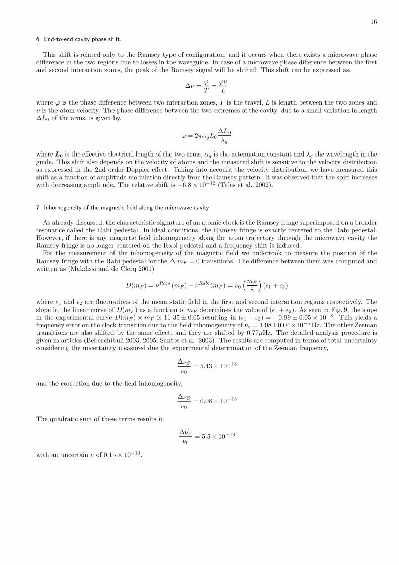
7. Inhomogeneity of the magnetic field along the microwave cavity
As already discussed, the characteristic signature of an atomic clock is the Ramsey fringe superimposed on a broaderresonance called the Rabi pedestal. In ideal conditions, the Ramsey fringe is exactly centered to the Rabi pedestal.However, if there is any magnetic field inhomogeneity along the atom trajectory through the microwave cavity theRamsey fringe is no longer centered on the Rabi pedestal and a frequency shift is induced.
For the measurement of the inhomogeneity of the magnetic field we undertook to measure the position of theRamsey fringe with the Rabi pedestal for the ∆ mF = 0 transitions. The difference between them was computed andwritten as (Makdissi and de Clerq 2001)
D(mF ) = νRam(mF ) − νRabi(mF ) = ν0
(mF
8
)
(ǫ1 + ǫ2)
where ǫ1 and ǫ2 are fluctuations of the mean static field in the first and second interaction regions respectively. Theslope in the linear curve of D(mF ) as a function of mF determines the value of (ǫ1 + ǫ2). As seen in Fig. 9, the slopein the experimental curve D(mF ) × mF is 11.35 ± 0.05 resulting in (ǫ1 + ǫ2) = −0.99 ± 0.05 × 10⁻⁸. This yields afrequency error on the clock transition due to the field inhomogeneity of νz = 1.08±0.04×10⁻⁵ Hz. The other Zeemantransitions are also shifted by the same effect, and they are shifted by 0.77µHz. The detailed analysis procedure isgiven in articles (Bebeachibuli 2003, 2005, Santos et al. 2003). The results are computed in terms of total uncertaintyconsidering the uncertainty measured due the experimental determination of the Zeeman frequency,
∆νZ
ν0= 5.43 × 10⁻¹³
and the correction due to the field inhomogeneity,
∆νZ
ν0= 0.08 × 10⁻¹³
The quadratic sum of these terms results in
∆νZ
ν0= 5.5 × 10⁻¹³
with an uncertainty of 0.15 × 10⁻¹³.

17
8. Rabi Pulling
Besides the chosen clock transition, there are the other six Zeeman transitions whose energies depend linearly onthe static magnetic field (C-field), ∆F = ±1; ∆mF = 0, as shown in Fig. 4. The separation between the neighboringtransition and the clock transition is 92 KHz which corresponds to a 13 µT C-field. These transitions have finite linewidth and hence they overlap the clock transition. Rabi Pulling is due to the superposition of the pedestals betweenadjacent transitions in the Zeeman spectrum. The transition signal of the first neighbor (mF = 0) is written as,
s (Ω0) = I(0)P (Ω0) + I(1)P3 (Ω0 − ωz) + I(−1)P3 (Ω0 + ωz) (9)
where P (Ω0) is the Ramsey probability and P3 (Ω0) is the Rabi pedestal, I(m) is the amplitude of transition m andωz = 2πνz. The probability P3 (Ω0) is given by the equation
P3 (Ω0) =b2
Ω20
[1 − cosΩ0τ ] ≃b2
Ω20
Expanding this equation in first order in Ω0
ωz
, we obtain
P3 (Ω0 − ωz) =b2
ω2z
(
1 + 2Ω0
ωz
)
(10)
P3 (Ω0 + ωz) =b2
ω2z
(
1 − 2Ω0
ωz
)
If we insert Eqs. 10 into Eq. 9 and rewriting terms we obtain
s (Ω0) = P (Ω0) + β0 + Ω0β1 (11)
where
β0 =b2
(
I(1) + I(−1)
)
I(0)ω2z
(12)
β1 =2b2
(
I(1) − I(−1)
)
I(0)ω3z
From Eqs. 11 and 12 we see that the effect of the neighbors’ transition on the clock transition is expressed by a smalleven quantity β0 and an odd function β1. The odd function creates a deformation of the clock signal. When theneighbor transitions, mF = I and mF = −I, have the same amplitude the deformation vanishes. The frequency shiftinduced may be calculated by,
νRabi = −β1ωm
π∫
A (ωm, b, τ) f(τ)dτ
where A (ωm, b, τ) is the unperturbed transition probability and f(τ) is the velocity distribution. The Rabi pullingmay shift the Rabi pedestal and the Ramsey fringe. However, this effect is more pronounced for the Rabi pedestal,because the inclination of the pedestal is smaller than the Ramsey fringe, while the amplitude modulation is greater.Thus, with the same method used for the second-order Zeeman effect, we measured the shift between the pedestaland the associated fringe for each of the seven transitions.
The fractional frequency shift of the clock transition was determined in the same way for the field inhomogeneity(Makdissi and de Clercq 2001). From Fig. 4, we have observed that there is an asymmetry of 1.3% between thenearest-neighbor transition and the clock transition. We now can estimate the fractional Rabi pulling as 4.4× 10⁻¹¹.The corresponding pulling for the Ramsey fringe is smaller by a factor of l/2L; and its magnitude is 1.3 × 10⁻¹³
(Bebeachibuli 2003,2005).
9. Cavity Pulling
Cavity pulling arises from the variation of the microwave amplitude with frequency when the cavity is mistuned.It is nearly independent of mF , but it has a strong dependence on the microwave power and on the modulationamplitude. Our procedure to measure the cavity pulling is the same as was used to measure the magnetic fieldinhomogeneity. From Fig. 9 the measured pedestal shift is 3.76± 0.10 Hz and the induced effect on the Ramsey fringefor the cavity detuning is 1.27 × 10⁻¹³ for the clock transition (Bebeachibuli et al. 2003,2005).

18
FIG. 9 Frequency difference between the center of the Ramsey fringe and the Rabi pedestal as a function of the Zeemansublevels mF . The points deviate from the straight line because of the Rabi pulling effect. The applied C-field is B0 = 13 µT.
TABLE I Global accuracy budget
Frequency Shift Correction(1. × 10−13) Uncertainty(1. × 10−13)Red Shift −1. × 10−4
−5. × 10−5
2nd order Doppler −1.65 0.12Quadratic Zeeman 5.5 0.15
Cavity Pulling 1.27 0.09Rabi Pulling 1.3 0.05
Black Body Radiation −0.2887 0.004
F. Global Accuracy Budget
The accuracy of an atomic frequency standard is defined as the capacity of the standard to produce a frequencythat is in agreement with the definition of the second. It is expressed as a relative uncertainty (∆ν
υ0
), relative to thesecond definition. Applying the several corrections to our frequency standard, their corresponding uncertainties aretabulated in table I.
Finally, the global accuracy of the beam standard results in σC = 6.13×10⁻¹³. This value means that the precisionat which our frequency standard measures the clock transition frequency is 9 192 631 770 Hz. This uncertainty iscomparable with the available commercial beam clocks. The constructed device was an important step on the learningcurve for the Brazilian team towards the fountain clock development that will be described in the next section.
VI. CONSTRUCTION AND EVALUATION OF THE CESIUM FOUNTAIN CLOCK
Time and frequency metrology is a dynamic field. As the technology advances, new and more precise ways tomeasure time arise. The fountain clock is an important step with about three orders of magnitude improvement overthe current atomic beam clock. In order to master the state-of-the-art in the field of time and frequency standards,we decided to undertake development of an atomic fountain clock.
19
Why is a fountain clock better than the conventional atomic beam?
The Ramsey two-interaction-zones technique demonstrates that the full-width-half-maximum (FWHM) of the cen-tral fringe is proportional to (1/T ) or (υ/L). This imposes two limits in the achievement of narrower Ramsey fringeand hence improvements over the accuracy of thermal beam clock: the cavity length L increment and the atomicvelocity (υ) reduction. The thermal atomic beam cannot be made slower than 70 ms−1 due to the intrabeam collisionsand velocity distribution. The length of cavity is limited by the beam shape and loss of the atoms. Thus the shapeof velocity distribution and correct geometry put an upper limit on the thermal atomic beam clock. A typical tubewith a 1 m drift region and velocity of 100 ms−1 results in a 10 ms interaction time or 50 Hz line width.
In the 1950s Zacharias (Ramsey 1963) proposed a device in which slow atoms from a thermal source were directedvertically upwards and then allowed to drop under gravity. This scheme could provide an interaction time of morethan 1 second, but initial attempts were unsuccessful due to atomic velocity dispersion at ambient temperature.However, with the advent of laser cooling and trapping techniques (Metcalf and Straaten 1999), with much reducedatomic velocity dispersion, the door was opened to reconsider the Zacharias approach. In the last decade it wassuccessfully implemented with the name of the atomic fountain clock (Kasevich et al. 1989, Clairon et al. 1991).By using laser cooling and trapping techniques such as a Magneto Optical Trap (MOT), one can localize millions ofcesium atoms in a very small volume and at a temperature of a few µK. The average velocity of the atoms at thistemperature is of the order of 1 cm s−1. In the fountain clock the launching velocity is selected in such way that theatoms reach a height of 1 meter and then fall down along the same path under gravity. While the atoms travel up anddown they pass through the same microwave cavity. Each time the atoms pass through the cavity they experiencea π/2 pulse of microwave field. A typical height above the cavity is about 20 cm. So the effective interaction ofabout half a second can be easily achieved and results in reduction of the resonance line width by 100 fold comparedto the thermal beam clock. Besides the most advantageous aspect of line width reduction, another benefit of thefountain clock configuration is the trajectory reversal that removes the cavity end-to-end phase shift and eliminatesthe distributed cavity phase effects. The first fountain clock was developed at the Observatoire de Paris, France andexhibited a relative uncertainty of 1.1 × 10⁻¹⁵ (Clairon et al. 1996, Wynands and Weyers 2005).
A. Construction
1. Device description
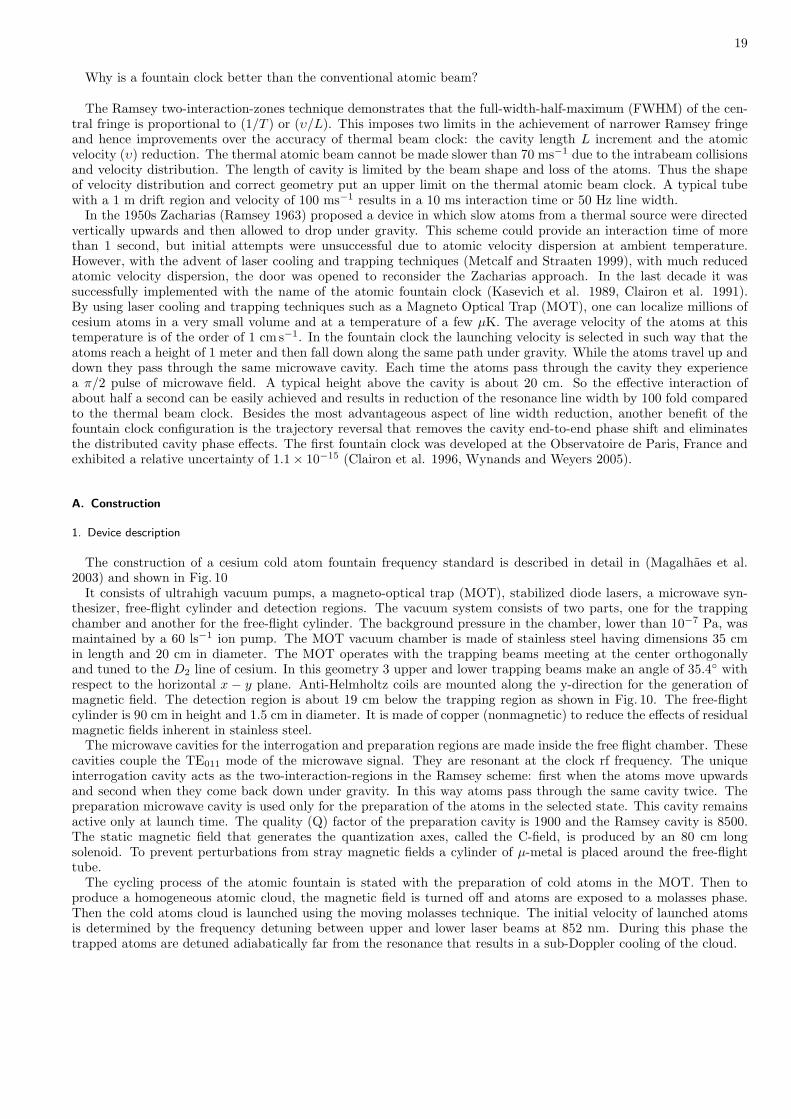
The construction of a cesium cold atom fountain frequency standard is described in detail in (Magalhaes et al.2003) and shown in Fig. 10
It consists of ultrahigh vacuum pumps, a magneto-optical trap (MOT), stabilized diode lasers, a microwave syn-thesizer, free-flight cylinder and detection regions. The vacuum system consists of two parts, one for the trappingchamber and another for the free-flight cylinder. The background pressure in the chamber, lower than 10−7 Pa, wasmaintained by a 60 ls−1 ion pump. The MOT vacuum chamber is made of stainless steel having dimensions 35 cmin length and 20 cm in diameter. The MOT operates with the trapping beams meeting at the center orthogonallyand tuned to the D2 line of cesium. In this geometry 3 upper and lower trapping beams make an angle of 35.4 withrespect to the horizontal x − y plane. Anti-Helmholtz coils are mounted along the y-direction for the generation ofmagnetic field. The detection region is about 19 cm below the trapping region as shown in Fig. 10. The free-flightcylinder is 90 cm in height and 1.5 cm in diameter. It is made of copper (nonmagnetic) to reduce the effects of residualmagnetic fields inherent in stainless steel.
The microwave cavities for the interrogation and preparation regions are made inside the free flight chamber. Thesecavities couple the TE011 mode of the microwave signal. They are resonant at the clock rf frequency. The uniqueinterrogation cavity acts as the two-interaction-regions in the Ramsey scheme: first when the atoms move upwardsand second when they come back down under gravity. In this way atoms pass through the same cavity twice. Thepreparation microwave cavity is used only for the preparation of the atoms in the selected state. This cavity remainsactive only at launch time. The quality (Q) factor of the preparation cavity is 1900 and the Ramsey cavity is 8500.The static magnetic field that generates the quantization axes, called the C-field, is produced by an 80 cm longsolenoid. To prevent perturbations from stray magnetic fields a cylinder of µ-metal is placed around the free-flighttube.
The cycling process of the atomic fountain is stated with the preparation of cold atoms in the MOT. Then toproduce a homogeneous atomic cloud, the magnetic field is turned off and atoms are exposed to a molasses phase.Then the cold atoms cloud is launched using the moving molasses technique. The initial velocity of launched atomsis determined by the frequency detuning between upper and lower laser beams at 852 nm. During this phase thetrapped atoms are detuned adiabatically far from the resonance that results in a sub-Doppler cooling of the cloud.

20
FIG. 10 The scheme of the atomic fountain. The C-field region is about 79 cm high. The microwave cavity is 29 cm above themagneto optical trap and the detection zone 17 cm below the trap. The atomic populations, NF=3 and NF=4, are measuredatomic fluorescence.
The principal laser source for trapping and cooling the atoms is a diode laser system model TA 100 from TOPTICA.The laser is locked to the reference Cs cell using the conventional saturated absorption technique. In the referencesystem an acousto-optic modulator (AOM) shifts the laser frequency and provides the detuning control for the MOTand sub-Doppler cooling phase. The optical output from the TA 100 is divided by using polarizing cubes, and eachbeam passes through separate AOMs. The voltage controlled oscillator (VCO) that supplies RF signal to these twoAOMs insures that they are phased-locked for the MOT and optical molasses production. For launching the atoms,a frequency difference is introduced between the upper and lower beams by an external digitally derived synthesizer(DDS) through the two AOMs. A repumper consisting of an external cavity diode laser system is used to pumpthe atoms from 6 2S1/2 F = 3 → 6 2P3/2 F = 4. A part of the laser beam is split and propagated through anotherreference Cs cell while the rest of the repumper maintains stability and correct functioning of the MOT. A thirddiode laser (SDL5412-H1) is used for the detection of atoms. It is locked to the 6 2S1/2 F = 4 → 6 2P3/2 F = 5transition. The detection system is located just below the MOT chamber. Two light beams having 6 mm separationare generated. One is in resonance at the 6 2S1/2 F = 4 → 6 2P3/2 F = 5 transition and the second beam is a
composition of two frequencies: the repumping beam frequency at the 6 2S1/2 F = 3 → 6 2P3/2 F = 4 transition and
the 6 2S1/2 F = 4 → 6 2P3/2 F = 5 resonance frequency. Therefore atoms in both hyperfine levels can be detected.The fluorescence detection of these two beams is carried out by using two PIN photodiodes with separate collectionoptics. The Ramsey fringes are observed by the measurements of the ratio
p =NF=4
NF=4 + NF=3
where NF=3 and NF=4 are the populations of the atoms in F = 3 and F = 4 levels. Polarization maintaining opticalfibers are used to deliver the laser power to the vacuum chamber. The optical power of the beam is about 11 mWand diameter is about 28 mm.

21
FIG. 11 Fountain clock microwave synthesizer
Using this cycling process, and launching the cold atoms 10.5 cm above the microwave cavity, we obtained a 1.7 Hzwide Ramsey central fringe. With this signal, the short-term stability was 6.6 × 10⁻¹².
2. Microwave synthesizer
To produce the interrogation signal to the atomic fountain experiment, a microwave synthesizer was constructedwith the valuable collaboration of the LNE-SYRTE (Laboratoire national de metrologie et d’essais–Systemes deReference Temps-Espaces) time-and-frequency team. This chain, shown in Fig. 11 uses a similar topology to somedevices already operating with their atomic frequency standards [4]. It has the same core idea used in the NIST chain,that is to generate a signal with the best spectral characteristics of high performance oscillators using phase-locked-loop techniques. The main parts of the synthesizer are the three oscillators: 4.596 GHz (DRO - Dielectric ResonantOscillator - 4R596-10SF - Omega Technologies), 10 MHz (BVA - OCXO 8600 - Oven Controlled Crystal Oscillator -Oscilloquartz) and 100 MHz (500-07542A - Wenzel Associates Inc). The 100 MHz crystal oscillator is phase lockedto the BVA at low frequencies (below 30 Hz), providing an output signal at 100 MHz with phase noise characteristicssuperior to each component individually. This 100 MHz signal is then doubled and inserted into a sampling mixer(RF - Reference Frequency input), which performs the subtraction of the 23rd harmonic of this input (4.6 GHz) withthe main harmonic signal coming from the DRO at 4.596 GHz (LO - Local Oscillator input). The output signal fromthe sampling mixer (IF - Intermediate Frequency) is compared with an external 29.5 MHz frequency, supplied by aDDS (SR345 - Stanford Research Systems) that uses the BVA as an external reference. This comparison provides thephase locking of the DRO, allowing modulation through the DDS programming. The other DRO output is connectedto a waveguide filter whose band is centered on its first harmonic at 9.192 GHz. The signal output has -15 dBmof output power, that is more than enough to feed the resonant cavity with a quality factor better than 5000 andminimizes spurious fields from connection leakages. The direct modulation of the DRO also provides an excellentway to increase the step resolution of the chain. Since the frequency step in the SR-345 is microhertz, the divisionby 8 provides a double advantage. The first advantage is that the frequency step resolution is 2.5 × 10⁻⁷ Hz. Thesecond is provided by the fact that the signal synthesis is digitally performed, so the phase noise is not increasingwith frequency. Using this fact, and since the DDS maximal frequency is 30 MHz, the 29.5 MHz signal is set, and afrequency division by eight also divides the signal phase noise by the same amount, improving the quality of the signal.This synthesizer was compared to other similar chains, and the obtained stability was shown to be 9.7× 10⁻¹⁴τ−1/2.To supply the microwave preparation signal, part of the 200 MHz signal generated in the first synthesizer is used todrive a second high-frequency phase lock, in the same topology used as in the first chain. In this case, a DRO at9.192 GHz (10.84 dBm) is inserted into a sampling mixer and subtracted from the 46th harmonic of a 200 MHz signal

22
derived from the interrogation chain. The sampling mixer output is compared with a 7.3 MHz signal provided by aDDS (SR345 - Stanford) and phase locks the DRO. In order to avoid perturbing fields during the interrogation phase,after the atoms pass the preparation cavity, the signal is switched off by the temporal sequence controller. This isdone by using a switch with 80dB of isolation (F192A -General Microwave).
VII. CONSTRUCTION AND EVALUATION OF THE EXPANDING COLD ATOM CLOCK
There is a need for simple, compact atomic clocks due to their wide applications in defense, communication and spacetechnology. The relevant requirements for a good atomic clock depend significantly on the application. Compactnessand robust design are at a premium, and stability dominates over accuracy for space-based systems. Recently compactclocks implemented using microfabrication technology (but not using cold atoms) have been demonstrated by Kitchinget al. (2005a,b) and Knappe et al. (2006). In order to minimize the “footprint,” weight and power consumption ofmagnetic traps, surface-mount wire traps and atom chips enable atom traps in various geometries. Robustness andmechanical stability can be achieved by using microfabricated wires (Feenstra et al. 2004 and references therein).NIST scientists demonstrated a chip-scale atomic clock based on coherent population trapping in 2004. Recentlyinterest has been focused on the development of compact clocks where a trade-off between size and performance mustbe taken into account. In a recent example a trapped cloud of cesium atoms was prepared, interrogated within themicrowave cavity. The resulting performance was a 14 Hz width of Ramsey central fringe and 10−12τ−1/2 projectedstability (Tremine et al. 2004). In the view of the great potential for the development of the cold-atom compact clock,we have also started a research program for the development of compact cesium cold-atom clocks in addition to thecesium beam and fountain clocks.
A. Construction
The Brazilian compact cold-atom clock is based on a Rabi profile and the Ramsey Method and is made from afreely expanding cloud of cold cesium atoms. Cold cesium atoms are prepared and trapped in a magneto-optical trap(MOT). A microwave antenna is used to provide the microwave radiation for the clock transition, which is detectedby the fluorescence from the optically pumped excited states.
Figure 12 illustrates the simplified schematic diagram. A cesium vapor cell can be pumped to a base pressure ≃10−7 Pa. A temperature-controlled reservoir allows regulating the amount of Cs atoms into the glass cell. Around theglass cell two main coils produce the magnetic field for magneto-optical trapping of the atoms and a set of compensationcoils guarantee a field-free environment for the atomic cloud expansion. Atomic densities ≃ 1010 cm−3 are typicallymeasured by fluorescence. Two stabilized diode lasers provide the frequencies necessary to produce the cooling andrepumping light. The relevant transitions excited by the lasers are the 6 2S1/2 F = 4 → 6 2P3/2 F = 5 cycling
transition and the 6 2S1/2 F = 3 → 6 2P3/2 F = 4 repumping transition, that prevents atoms from accumulating inthe F = 3 ground state during the trapping phase of the experiment. The trapping and repumping beams are spatiallyoverlapped and divided along three orthogonal axes. Two counterpropagating beams intersect in the horizontal x− yplane and the third beam is directed along the z axis, perpendicular to the x − y plane and passing through thepoint of intersection of the the other two beams. Each laser beam carries about 12 mW of power in a 2.5 cm waist.Fluorescence light from the intersection region is imaged onto a calibrated detector located 10 cm from the cell center.A microwave antenna of quarterwave is positioned perpendicular to the vertical axis, outside the glass cell and about3 cm from the atoms. The radiation pattern of the antenna was determined so as to position the atoms in thehigh-intensity region. The antenna was coupled to a microwave chain, generating 9.192 GHz. About 2 × 10⁸ atomsare captured in the MOT and become the sample for performing the microwave transition and to lock the oscillatorchain. The time sequence used to observe the microwave resonance is the following: for about 800 ms, the magneticfield of the MOT, as well as the lasers, are turned on, allowing capture and accumulation of atoms. The repumpinglaser and the MOT coils are then turned off until the end of the sequence. For the next 23.9 ms the trapping laseris still on and will promote optical pumping of the atoms to the 6 2S1/2 F = 3 state, after which it is turned off. Atthis stage the atomic cloud is in free expansion and remains so for the next few ms. Then the first microwave pulseof duration 2 ms is applied. After a quiescent interval of 8 ms, a second pulse of microwave can be applied or not. Atthe end, the trapping laser is turned back on for 50 ms and the fluorescence of atoms at 6 2S1/2 F = 4 is detected.
The atoms originally populated in 6 2S1/2 F = 3 are transferred to 6 2S1/2 F = 4 by the microwave field. A variableattenuator is placed on the microwave source such that a π-pulse is applied during the ∆tp period (Rabi method). Inthe case of two consecutive pulses ∆tp, the microwave power is adjusted to produce two π/2-pulses (Ramsey method).The temporal sequence for the experiment is illustrated in Fig. 13. The fluorescence detection system is composedof a collecting lens that images the cloud onto a calibrated photodetector. Once the resonance line is obtained, a

23
FIG. 12 Schematic diagram of experimental setup for expanding cold atomic clock.
FIG. 13 Timing sequence of applied pulses used to control the expanding cold-atom clock experiment.
modulation of the microwave frequency allows generates the error signal used to lock the oscillator on the atomicresonance. The microwave chain is phase-locked (phase-locked-loop) to the 10 MHz output of a commercial standardoscillator source (Magalhaes et al. 2006 , Muller et al. 2005).
B. Evaluation
Two experiments were conducted using the cold cloud of atoms interacting with microwave radiation. In the firstexperiment investigated the Rabi frequency coupling the upper and lower levels by using microwave B-field amplitude

24
FIG. 14 Resonance observed in the expanding cold-atom experiment using 12 ms of interrogation time in a Rabi method.
30 µG. The pulse duration (∆tp) was varied 2-20 ms and the growing population of 6 2S1/2 (F = 4) atoms could beobserved, reaching a maximum and then decreasing. This is the first cycle of the Rabi oscillation. The pulse time∆tp has been fixed to produce the maximum transference to the 6 2S1/2 (F = 4) level, which corresponds to a π-pulse.At 30 µG microwave amplitude, ∆tp = 12 ms and fixing the pulse duration, the microwave frequency was swept,generating the resonance curve as shown in Fig. 14. Fitting the resonance curve with a Lorentzian shape we obtaina full width at half-maximum (FWHM) of 39 Hz. Comparing with the results reported by (Guillot et al. 1999) forthe first evaluation of the atomic clock with cooled atoms in a cell, a factor of 6 improvement is obtained with afreely-expanding cold atom cloud. Our results are however compatible with the results by (Sesko and Weiman 1989),where 44Hz FWHM was observed in an experiment similar to the one here presented.
If our observed line width of 39 Hz is compared to NIST-6 (NBS-6) atomic clock, 26 Hz, which was obtained with aCs beam and a 4 m long transition region (Glaze et al. 1977), we can appreciate the great potential for the use of thecold-atom Rabi interrogation method as a clock transition. In terms of line width vs. length of transition region, weare three orders of magnitude better than conventional beam clocks. Compared to atomic fountains, whose typicalline width is 1 Hz, we see that there is also room for improvement when just a cloud of cold atoms is used.
The resonance observed in Fig. 14 was used as a clock transition to lock a local oscillator. The generated errorsignal was used to evaluate the comparison thus obtaining the Allan variance. The frequency stability of the producedclock is presented in Fig. 15, resulting in an Allan standard deviation of σ(τ) = (9± 1)× 10−11τ−1/2, already a goodstability considering the simplicity of the device. There is still a lot of room for improvement, and we should beable to obtain a result about one order of magnitude better for short-term stability. It should be straightforward toextend the present demonstration technology to make a compact high performance, all-optical atomic clock, with along lifetime of Cs supply compared to present Cs tube lifetimes.
In the second experiment, a sequence of two pulses during the interrogation time was used in an attempt toimplement the Ramsey method. In this case we have used ∆tp = 2 ms and ∆tb = 8 ms, with a power level suchthat a π/2-pulse condition for each interrogation is satisfied. The existence of fringe is quite clear but with verypoor contrast. The reason for this poor contrast are not yet entirely understood. It seems that the fringes exhibit agreat narrowing of the transition but the poor contrast makes it hard to lock an oscillator as has been done for thesingle-interaction-zone, Rabi profile. The possible reasons for this poor contrast are under investigation.

25
FIG. 15 Frequency stability plot for the expanding cold-atom clock against a commercial Agilent 5071A reference.
VIII. CONCLUSION
In this article we have discussed the important applications of atomic clocks, their working principles, based onthe two separated microwave interaction zones, and the different types of cesium atomic clocks. We have thoroughlydescribed the cesium-based Brazilian program, construction and evaluation.
We have designed and developed the cesium beam clock, fountain clock and compact cold atom clock under theresearch program on time and frequency metrology in Brazil. These are the first thermal and cold atoms standardsfully constructed in Latin America.
The construction of the Brazilian frequency standards family has been described in detail. It consists of cesiumoven, beam chamber, vacuum systems, microwave cavity, C-field, graphite discs, diode laser, diode laser driver andstabilizer, microwave synthesizer, magneto-optical trap (MOT) and free flight cylinder.
Evaluation of the frequency standards was performed and based on experimental data. Short term stability ofthe clocks was determined from the square root of the Allan variance. The short term stability of the beam clock,fountain clock and compact expanding cold atom clock were determined to be σ(τ) = (6.6 ± 0.2) × 10−10 τ0.5±0.1,σ(τ) = (6.6 ± 0.2) × 10−12 τ0.5, and σ(τ) = (9 ± 1) × 10−11 τ0.5 respectively.
The observed line width in case of Brazilian expanding cold atom clock is 39 Hz with respect to the Rabi profile.With a 0.2 m long transit region the typical line width of the fountain clock is about 1 Hz. This illustrates the greatpotential of compact cold atomic clocks.
We have discussed and evaluated all the possible frequency offsets due to perturbations. Optimal Rabi frequency,second order Doppler shift, second order Zeeman shift, cavity pulling, end-to-end cavity phase shift and inhomogeneityof the magnetic field along the microwave cavity were all determined from the analysis of Ramsey central fringe andRabi pedestal. The global accuracy budget of these frequency shifts with corrections and uncertainties was tabulated.Finally the global accuracy of the beam clock is determined to be 6.13 × 10⁻¹³. The future program is to extendpresent demonstrated technology to achieve a high-performance, compact, cold-atom clock with long life and continueefforts toward developing the atomic fountain for use as a high-performance reference as well as to contribute to TAIand perform fundamental physics research.

26
Acknowledgments
The authors acknowledge the financial support obtained from FAPESP (CEPID/CEPOF), CAPES-COFECUP andprograma TIB-CNPq. We also acknowledge the important collaboration with LNE-SYRTE. M.A. also acknowledgessupport from the higher education commission of Pakistan.
IX. REFERENCES
Abali B, Stunkel CB and Benveniste C. 1997. Clock synchronization on a multicomputer. J. Parallel Distrib.Comput. 40: 118-130.
Allan DW. 1966. Statistics of atomic frequency standards. Proc. IEEE. 54: 221-230.
Allan DW. 1989. In search of the best clock: An update in: Frequency standards and metrology. Springer,Berlin, Heidelberg.
Allan DW, Kusters J and Griffred R. 1994. Civil GPS timing application. Proc. of ION GPS-04. 25-32.
Audoin C and Guinot B. 2001. The Measurement of Time: Time, Frequency and The Atomic Clock. CambridgeUniversity Press.
Bauch A. 2003. Cesium atomic clock: function, performance and applications. Meas. Sci. Technol. 14:1159-1173
Bebeachibuli A, Santos MS, Magalhaes DV, Teles F and Bagnato VS. 2003. Characterization of the frequencypulling by magnetic field oscillation of the Brazilian Cs atomic frequency standard. Proceedings of the 2003IEEE International frequency control symposium. 95- 99.
Bebeachibuli A, Santos MS, Magalhaes DV, Muller ST and Bagnato VS. 2005. Characterization of the mainfrequency shifts for the Brazilian Cs atomic beam frequency standard. Braz. J. Phys. 35: 1010-1015.
Bize S, Laurent P, Abgrall M, Marion H, Maksimovic I, Cacciapuoti L, Grunert J, Vian C, Pereira dos SantosF, Rosenbusch P, Lemonde P, Santarelli G , Wolf P, Clairon A, Luiten A, Tobar M and Salomon C. 2005. Coldatom clocks and applications. J. Phys. B. 38: S449 - S468.
C.C.D.S. 1980 Proc. of the Consulative Committee for the Definition of Second Bureau International des Poidset Mesures, Sevres, France.
Cazenave A, Bonnefond P, Dominh K, Schaeffer P. 1997. Caspian Sea-Level From TOPEX/POSEIDON Al-timetry Level Now Falling : Geophys. Res. Lett. 24: 881-884.
Kasevich M, Riis E, Chu S, de Voe R. 1989. RF Spectroscopy in an Atomic Fountain, Phys. Rev. Lett. 63:612-615.
Clairon A, Salomon C, Guellati S, Phillips WD. 1991. Ramsey Resonance in a Zacharias Fountain, Europhys.Lett. 16: 165-170.
Clairon A, Ghezali S, Santarelli G, Laurent Ph, Lea SN,Bahoura M, Simon E, Weyers S and Szymaniec K. 1996.Preliminary accuracy evaluation of a cesium fountain frequency standard. Proceedings of the 5th Symposiumon Frequency Standards and Metrology 49-59.
Cutler LS. 2005. Fifty years of commercial caesium clocks. Metrologia 42: S90-S99.
Essen L and Parry JVL. 1957. The cesium resonator as a standard of frequency and time. Phil. Trans. R. Soc.A250: 510-514.
Feenstra L, Andersson LM and Schmiedmayer J. 2004. Microtraps and atom chips: Toolboxes for cold atomphysics. Gen. Rel. and Grav. 36: 2317- 2329.
Flambaum VV and Tedesco AF. 2006. Dependence of nuclear magnetic moments on quark masses and limitson temporal variation of fundamental constants from atomic clock experiments. Phys. Rev. C 73: 055501.
CGMP, 11th General Conference on Weights and Measures 1960.

27
CGPM, 13th General Conference on Weights and Measures 1967.
Godone A, Novero C, Tevalle P and Rahimullah K. 1993. New experimental limits to the time variations of gp(me / mp ) and α. Phys. Rev. Lett. 71: 2364-2366.
Guillot E, Pottie PE, Valentin C, Prtit P and Dimarcq N. 1999. Proceedings of the 1999 Joint meeting of theEuropean frequency and time forum and the IEEE International frequency control symposium. 81-84.
Hafele JC and Keating RE. 1972. Around-the-world atomic clocks: Predicted relativistic time gains. Science177: 166-168.
Jesperson J and Fitz-Randolph J. 1999. From sundials to atomic clocks: understanding time and frequency.Dover Publications
Kitching J. 2005a. An atomic clock on a microchip. The Horological Journal, 147: 54-55.
Kitching J, Knappe S, Liew L, J Moreland J, Schwindt PDD, Greginov V, Shah V, Liew L, Moreland J, RobinsonHG, Hollberg L. 2005b Microfabricated Atomic Frequency References. Metrologia 42: S100S104
Knappe S, Schwindt PDD, Gerginov V, Shah V, Liew L, Moreland J, Robinson HG, Hollberg L and KitchingJ. 2006. Microfabricated atomic clocks and magnetometers. J. Opt. A: Pure Appl. Opt. 8: S318S322.
Knappe S, Shah V, Peter D, Schwindt D, Hollberg L, Kitching J, Liew LA and Moreland J. 2004. A microfab-ricated atomic clock. Appl. Phys. Lett. 85:1460- 1462.
Lyons H. 1948. Microwave frequency standards. Phys. Rev. 74: 1203.
Ma LS, Bi Z, Bartels A, Robertsson L, Zucco M, Windeler R.S, Wilpers G, Oates C, Hollberg L and DiddamsS.A 2004. Optical frequency synthesis and comparison with uncertainty at the 10-19 level. Science 303: 18431845.
Magalhaes DV, Santos MS, Bebeachibuli A, Teles F and Bagnato VS. 2003. Progress towards a Cs fountain asfrequency standard in Brazil. Proceedings of the 2003 IEEE International frequency control symposium. 132-135.
Magalhaes DV, Muller ST, Bebeachibuli A, , Alves RF and Bagnato VS. 2006. Comparative short-term stabilityfor a Cs beam and an expanding cold atomic cloud of Cs used as atomic frequency standards. Laser Physics.16: 1268-1271.
Makdissi A and de Clercq E. 1997. IEEE Trans. Instrum. Meas. 46: 112-116.
Makdissi A 1999. Ph.D. Thesis , University de Paris-Sud, 5844.
Makdissi A and de Clercq E. 1997. A Signal Approach Analysis of the Ramsey Pattern in Cesium BeamFrequency Standards, IEEE Trans. Instrum. Meas. 46: 112-116.
Makdissi A and de Clercq E. 2001. Evaluation of the accuracy of the optical caesium beam primary standardof BNM-LPTF. Metrologia. 38: 409 - 425 .
Marion H, Santos FP, Abgrall M, Zhang S, Sortais Y, Bize S, Maksimovic I, Calonico D, Grunert J, MandacheC, Lemonde P, Santarelli G, Laurent Ph, Clairon A and Salomon C. 2003. Search for variation of fundamentalconstants using atomic fountain clocks. Phys. Rev. Lett. 90: 150801-4.
McCaskill TB, Oaks OJ, Largay MM, Reid WG, Warren HE and Buisson JA. 1999. Performance of globalpositioning system block II/IIA/IIR on-orbit Navstar clocks. Proc. 31st Annual PTTI systems and applicationsMtg. 75-89.
Metcalf HJ and Straaten P van der.1999. Laser cooling and trapping. Springer, Berlin, Heidelberg, New York.
Monroe C, Robinson H and Wieman C. 1991. Observation of the cesium clock transition using laser-cooledatoms in a vapor cell. Opt. Lett. 16: 50- 52
Mowat JR. 1972. Stark effect in alkali-metal ground-state hyperfine structure. Phys. Rev. A 5: 1059 - 1062.

28
Muller ST, Magalhaes DV, Bebeachibuli A, Santos MS and Bagnato VS. 2005. Demonstration and observationof a frequency standard based on an expanding cold atoms cloud of cesium. Proceedings of the 2005 IEEEInternational frequency control symposium. 288-291.
Nelson RA, McCarthy DD, Malys S, Levine J, Guinot B, Fliegel HF, Beard RL and Bartholomew TR. 2001.The leap second: its history and possible future. Metrologia 38: 509-529.
Peik E, Lipphardt B, Schnatz H, Schneider T, and Tamm Chr. 2004. Limit on the Present Temporal Variationof the Fine Structure Constant. Phys. Rev. Lett. 93: 170801-4
Ramsey NF. 1950. A molecular beam method with separated oscillating fields. Phys. Rev. 78: 695-699.
Ramsey NF. 1963. Molecular beams. Oxford university press, Amen House, London E.C. 4. p 115-144.
Ramsey NF. 1990. Experiments with separated oscillatory fields and hydrogen masers. Rev. Mod. Phys.62:541-552.
Riehle F. 2004 Frequency Standards: Basics and Applications Wiley-VCH, Berlin.
Santos MS, Bebeachibuli A,Magalhaes DV, Teles F and Bagnato VS. 2003. Stability and reproducibility of aCs beam frequency standard. J. Metrology Society of India. 18: 139-145.
Sesko DW and Wieman CE. 1989. Observation of the cesium clock transition in laser-cooled atoms. Opt. Lett.14: 269 271.
Shapiro SS, Davis JL, Labach DE and Gregory JS. 2004. Measurement of the solar gravitational deflection ofradio waves using geodetic very-long-baseline interferometry data, 1979-1999. Phys. Rev. Lett. 92: 12101(1-4).
Shirley JH, Lee WD and Drullinger RE. 2001. Accuracy evaluation of the primary frequency standard NIST-7.Metrologia 38: 427 - 458.
Simon E, Laurent P and Clairon A. 1998. Measurement of the Stark shift of the cesium hyperfine splitting inan atomic fountain. Phys. Rev. A 57: 436-439.
Teles F, Magalhaes DV, Santos MS, Rovera GD and Bagnato VS. 2000. Construction and evaluation of the firstBrazilian atomic clock. IEEE Trans. Ultrason., Ferroelec., and Freq. Contr. 47: 1111-1114.
Teles F, Magalhaes DV, Santos MS, Bebeachibuli A and Bagnato VS. 2002. Characterization of the BrazilianCs atomic frequency standard: Evaluation of the major shifts. Metrologia 39: 135-141.
Teles F, Magalhaes DV, Santos MS, Bebeachibuli A and Bagnato VS. 2003. Optically operated Brazilian atomicclock: Description and evaluation. Laser Physics. 13: 175-179.
Tremine S, Guerandel S, Holleville D, Clairon A and Dimarcq N, 2004. 2004 IEEE International Ultrasonics,Ferroelectrics and Frequency Control Joint 50th Anniversary Conference, 65-70.
Udem TH, Holzwarth R and Hansch TW. 2002. Optical frequency metrology. Nature. 416: 233 - 237.
Uzan JP, 2003. The fundamental constants and their variation: Observational status and theoretical motivations.Rev. Mod. Phys. 75: 403- 455.
Vanier J and Audoin C. 1989. The Quantum Physics of Atomic Frequency Standards. Adam Hilger imprint byIOP Publishing LTD.
Vessot RFC and Levine MW. 1979. A test of the equivalence principle using a space-borne clock. Generalrelativity and gravitation. 10: 181-204.
Vessot RFC, Levine MW, Mattiso EM, Blomberg EL, Hoffman TE, Nystrom GU, Farrel BF, Decher R, EbyPB, Baugher CR, Watts JW, Teuber DL and Wills FD. 1980. Test of relativistic gravitation with space bornehydrogen maser. Phys. Rev. Lett. 45: 2081-2084.
Wu A and Feess B. 2000. Development and evaluation of GPS space clocks for GPSIII and beyond. Proc. 32ndAnnual systems and applications meeting 389-399.
Wynands R and Weyers S. 2005. Atomic fountain clocks.Metrologia 42:S64-S79.