the cern–eu high-energy reference field (cerf) facility for dosimetry at
TRANSCRIPT

7
Radiation Protection DosimetryVol. 102, No. 1, pp. 7–22 (2002)Nuclear Technology Publishing
THE CERN–EU HIGH-ENERGY REFERENCE FIELD (CERF)FACILITY FOR DOSIMETRY AT COMMERCIAL FLIGHTALTITUDES AND IN SPACEA. Mitaroff and M. SilariCERN, 1211 Geneva 23, Switzerland
Received April 2 2001, amended February 13 2002, accepted February 19 2002
REVIEW PAPER
Abstract — A reference facility for the calibration and intercomparison of active and passive detectors in broad neutron fieldshas been available at CERN since 1992. A positively charged hadron beam (a mixture of protons and pions) with momentumof 120 GeV/c hits a copper target, 50 cm thick and 7 cm in diameter. The secondary particles produced in the interaction traversea shield, at 90° with respect to the direction of the incoming beam, made of either 80 to 160 cm of concrete or 40 cm of iron.Behind the iron shield, the resulting neutron spectrum has a maximum at about 1 MeV, with an additional high-energy component.Behind the 80 cm concrete shield, the neutron spectrum has a second pronounced maximum at about 70 MeV and resembles thehigh-energy component of the radiation field created by cosmic rays at commercial flight altitudes. This paper describes thefacility, reports on the latest neutron spectral measurements, gives an overview of the most important experiments performed bythe various collaborating institutions over recent years and briefly addresses the possible application of the facility to measurementsrelated to the space programme.
INTRODUCTION
In its 1990 recommendations the International Com-mission on Radiological Protection (ICRP) stated thatexposure of civil aircrew has to be considered as beingoccupational(1). This has been translated into a legalrequirement in the European Union in 1996 by theCouncil Directive 96/29(2). The ICRP recommendationshave boosted several research activities worldwide aim-ing at determining dose equivalent rates for the variouscommercial routes as well as establishing experimentaland computational tools for dosimetry of aircrews. Inthis framework the European Union has sponsored since1992 coordinated actions with the aim to merge theexpertise of several research institutions in the field ofcosmic ray physics and dosimetry(3–6). A wide range ofactive instruments and passive devices has beenemployed in several measurement campaigns, mainly onboard commercial flights but also on some dedicatedflights (see, for example, References 3, 4, 7–13).
If both the energy and angular response character-istics of a device and the energy and direction distri-bution of the radiation field to be determined are wellknown (either experimentally or theoretically), theresponse data can be folded with the field data to obtaina response correction factor. In practice these conditionsare rarely met for in-flight measurements. An alternativeapproach is thus to determine the response of the deviceeither in the radiation field of interest (a ‘fieldcalibration’) or in an experimental radiation field of suf-
Contact author E-mail: marco.silari�cern.ch
ficiently similar characteristics (a ‘simulated workplacefield’) (Figure 1).
The direct field calibration in aircraft requires areference instrument in principle capable of determiningthe true value of ambient dose equivalent for all radi-ation components and energies. In this respect thetissue-equivalent proportional counter (TEPC) ispresently considered the instrument best suited for fieldcalibration in the cosmic radiation field at flightaltitudes(14). However, the availability of a referenceradiation facility providing particle composition andspectral fluences similar to those in the cosmic radiationfield at commercial flight altitudes (10–20 km) is ofobvious interest. The EU funded programmes placedsignificant emphasis on calibration and characterisationof detectors. An important element in these programmesis the simulation of the cosmic ray field at aircraft alti-tudes at an experimental facility available at CERN,which provides a reference base for both passive andactive instruments(15).
The facility is a development of an idea conceivedby Stevenson in 1987, when an experimental area wasset up to study the spatial distribution of hadron andlow-energy neutron fluence and of absorbed dose in thecascades induced in iron and lead calorimeter structuresirradiated by high-energy hadron beams(16–19). TheCERN–EU reference radiation facility was set up in1992 and subsequently upgraded to its present form in1993. Minor modifications (addition of some extrashielding just upstream of the dump and of an accessmaze), which did not affect the particle spectra at thereference exposure locations, were made in 1997. Inaddition to the interest for testing active instrumentation

A. MITAROFF and M. SILARI
8
and passive detectors used around high-energy particleaccelerators, this reference field is considered to be suf-ficiently similar to the cosmic ray field encountered at10–20 km altitude such that instrumentation can betested, inter-compared and calibrated at CERN and sub-sequently used for in-flight measurements on aircraft.The facility actually provides a mixed field of neutrons,photons, muons, electrons, protons and pions — and itis widely used to test both low- and high-LET sensitivedevices — but the main component is represented by theneutron field. Although there are several laboratoriesoffering monoenergetic reference neutron fields, such asPTB in Braunschweig, Germany, PSI in Villigen, Switz-erland and UCL in Louvain-la-Neuve, Belgium, theCERN field is unique in providing a broad neutron spec-trum specifically adapted to the above purpose.
The aim of the present paper is to describe thefacility, which has previously been illustrated only intwo conference proceedings(20,21), to report on the latestneutron spectral measurements, to give an overview ofthe most important experimental investigations carriedout by the various collaborating institutions over recentyears, and to address briefly its possible application tomeasurements related to the space programme.
THE CERN–EU HIGH-ENERGY REFERENCEFIELD (CERF) FACILITY
The CERN–EU high-energy Reference Field (CERF)facility is installed in one of the secondary beam lines(H6) from the Super Proton Synchrotron (SPS), in theNorth Experimental Area on the Prevessin (French) site
������� ��������
� ������������������
���������������
������������ ���!"���
�
���
���
#��
$���
�������������� �%������%��������!�����������%��
���� ������ ���
&���!������%�%���������'�����������������! �������'���
(���������)��������
&���!����%�����������%������������'��������������������������%�����%*� ��%�� ���%��!
������!�����%� ���%��������
+#����,+���- $.����,$+���-
�
���
���!��
!"���
Figure 1. The cosmic radiation field in the atmosphere and its simulation at CERN.
of CERN (Figures 2 and 3). A positive hadron beamwith momentum of usually 120 GeV/c is stopped in acopper target, 7 cm in diameter and 50 cm in length,which can be installed in two different positions insidean irradiation cave. In the past 205 GeV/c positive andnegative hadron beams (respectively a mixture of about2/3 protons and 1/3 positive pions or negative pionsonly) were also used. The secondary particles producedin the target traverse a shielding, on top of these twopositions, made up of either 80 cm concrete or 40 cmiron. These roof shields produce almost uniform radi-ation fields over two areas of 2 � 2 m2 located atapproximately 90° with respect to the incoming beamdirection, each of them divided into 16 squares of 50� 50 cm2. Each element of these ‘grids’ represents a
/�����%���������������� ���%
&���������� ���%
0��
���1'����%�
���!����%������������������ ���%
(�
Figure 2. Axonometric view of the CERF facility in the NorthExperimental Hall on the Prevessin site of CERN as modelledin FLUKA. The side shielding on the Saleve side is removedto show the inside of the irradiation cave with the copper target
set-up.

THE CERN–EU REFERENCE FIELD (CERF) FACILITY
9
reference exposure location. Additional measurementpositions are available behind the lateral shielding of theirradiation cave, at the same angles with respect to thetarget as for the two roof positions. Shielding is either80 cm or 160 cm concrete, and at both positions 8additional exposure locations (arranged in 2 � 4 grids
2 0���%����3������� ��� ���%��!
0��4.
5��������0
���00
���!��
2
���22
(���'��������
$".
�"+$".
+"6
7"�
5��������
�����������
������������
��%���������
��������
��%���������
�$ �� �8 �$7
��
�7
�+ �6
�#
�. �$�
�$$
�$�
�$+
�$�
�$.
,*-
,�-
Figure 3. (a) Plan and sectional views of the CERF facility. (b) The reference grid with the 16 exposure locations used on theconcrete and iron roof-shields.
made up of the same 50 � 50 cm2 elements) are pro-vided. The nominal measurement locations (the refer-ence field) are at the centre of each square at 25 cmheight above floor, i.e. at the centre of a 50 � 50 �50 cm3 air volume, where the radiation field is calcu-lated. The intensity of the primary beam is monitored

A. MITAROFF and M. SILARI
10
by an air-filled precision ionisation chamber (PIC) atatmospheric pressure, placed in the beam just upstreamof the copper target, connected to a current digitisingcircuit. One PIC-count corresponds (within �10%) to2.2 � 104 particles impinging on the target. The protonbeam is slow-extracted from the SPS over a few seconds(typically 2.6 s spill within an SPS cycle of 14.4 s, or5.1 s spill every 16.8 s). During the spill the beam inten-sity is constant, thus producing a constant radiation fieldat the exposure locations. Typical values of dose equiv-alent rates are 1–2 nSv per PIC-count on top of the40 cm iron roof-shield and about 0.3 nSv per PIC-countoutside the 80 cm concrete shields (roof and side). Byadjusting the beam intensity on the target one can varythe dose equivalent rate at the reference positions, typi-cally in the range from 25 �Sv.h−1 to 1 mSv.h−1 on theiron roof-shield and from 5 to 600 �Sv.h−1 on the 80 cmconcrete roof or lateral shield. The energy distributionsof the various particles (mainly neutrons, but also pho-tons, electrons, muons, pions and protons) at the variousexposure locations have been obtained by Monte Carlosimulations performed with the FLUKA code(22–25).Details of the latest simulations are given elsewhere(21).Here we shall just recall that the entire experimentalarea was accurately modelled using a combinatorialgeometry. Calculations were performed for fourcases, i.e. beam momentum of 120 GeV/c or205 GeV/c and positive or negative particles. The205 GeV/c and the negative 120 GeV/c beams wereused in the past, whilst since 1996 all experimentsare performed with a beam of 120 GeV/c positive par-ticles. The neutron and photon energy distributionscalculated for a primary beam of positive particleswith 120 GeV/c momentum (35% protons, 61% pionsand 4% kaons, as determined experimentally) areshown in Figures 4(a) and 4(b). It should be noted thatthese are absolute energy distributions per primary beamparticle incident on the copper target, obtained by multi-plying the FLUKA differential fluences (in particle/GeV/cm2/primary) by the width of the energy bin.
In general the neutron energy distributions do notchange in shape from 120 GeV/c to 205 GeV/c, foreither positive or negative particles, and only the absol-ute fluence per incident particle is larger for the higherenergy. The spectrum outside the iron shield is domi-nated by neutrons in the 0.1–1 MeV range. The energydistribution outside the concrete shield shows anadditional large relative contribution of 10–100 MeVneutrons. Therefore these exposure locations providewide spectrum radiation fields well suited to test dosi-metric instrumentation under different conditions. Thelatter, in particular, reproduces fairly closely, althoughnot exactly, the neutron field produced by cosmic raysat commercial flight altitudes (Figure 4(c)). Since theCERF neutron field reproduces approximately the fieldat flight level, and because the shape of the neutronenergy distribution in the atmosphere does not changemuch with altitude and latitude, the CERF spectrum is
$��7
$��+
$���
$��.
$��#
$��� $��$ $ $� $�� $�7 $�+ $�� $�. $�# $�6 $�8
����!��,��-
�����������%��� ���%
&���������� ���%��$�
��������������� ���%
�� �,�
��-
$��+
�
�
$���
�
�$��.
�
�
$��#
�� �,�
��-
$�+� �
$��� �
$�.� �
$�#� �
$�6� �
$�8
��������������� ���%
�����������%��� ���%
&���������� ���%
�"��
�"$�
�"$�
�"��
�
���9��������������:����������.2��������7�:������
�� �,�
��-
$��� $��$ $ $� $�� $�7 $�+ $�� $�. $�# $�6 $�8
����!��,��-
����!��,��-
,�-
,*-
,�-
Figure 4. Neutron (a) and photon (b) spectral fluences on theconcrete roof-shield, on the iron roof-shield and on the80 cm thick concrete side-shield (neutrons or photons perprimary beam particle incident on the copper target). (c)Comparison of the CERF neutron spectrum on the concreteroof-shield (position 6 on the grid of Figure 3(b)) withthe neutron spectrum at an altitude of 10.6 km (35,000 feet)as calculated by Heinrich et al (26). The total fluence is
normalised to unity.

THE CERN–EU REFERENCE FIELD (CERF) FACILITY
11
considered in most cases a sufficiently good representa-tive of the neutron field at cruising altitude irrespectiveof route. A correction should usually be applied to takeaccount of the difference in response of the device undertest for the CERF spectrum relative to the neutron spec-trum in the atmosphere, but this correction is not verysensitive to the sometimes large uncertainties in thehigh-energy neutron response data of the device (see,for example, Reference 27. The neutron spectrumbehind the side 80 cm thick concrete shield is similar tothe spectrum on the concrete roof-shield, but presentsan increased low energy tail due to backscatter. On theother hand, it is much less affected by the muon back-ground (see below). The fluence rate of other hadronsis much lower than that of neutrons. As seen from Fig-ure 4(b), the photon fluence is almost one order of mag-nitude less than that of neutrons on the iron roof-shield,but almost a factor of two higher than the neutron flu-ence on the concrete roof-shield, because of the contri-bution from (n,�) reactions. The electron fluence isabout one order of magnitude less than that of neutronsand the muon fluence almost three orders of magnitudeless. However, an additional muon component is alsopresent, which comes directly from the upstream H6beam line and adjacent lines, as well as from pion decayin the beam line. These muons stream over the concreteand iron roof-shields. Their intensity depends on variousfactors which are not under direct control, such as theintensity of secondary beams in neighbouring beamlines. This contribution is discussed in some moredetail below.
The accuracy of the calculated neutron spectralfluences was verified in the past by extensive measure-ments made first with a BF3 proportional counterenclosed in polyethylene cylinders of differentthickness(28) and subsequently with a Bonner spherespectrometer (BSS). Past measurements were done witha standard BSS(21): a 3He proportional counter employedbare and within a set of five polyethylene spheres
Table 1. Experimental and calculated absolute response of the extended Bonner Sphere Spectrometer to the broad neutronspectrum on the concrete roof-shield of CERF, for a 120 GeV/c positive hadron beam (61% pions, 35% protons and 4%
kaons) impinging on the copper target.
Sphere Response(counts per incident hadron on the copper target)
Experimental Calculated Ratio (calc/exp)
81 mm + cadmium (1.53 � 0.08) � 10�5 (1.54 � 0.10) � 10�5 1.01 � 0.0881 mm (2.24 � 0.10) � 10�5 (2.29 � 0.14) � 10�5 1.02 � 0.08108 mm (3.02 � 0.13) � 10�5 (2.96 � 0.24) � 10�5 0.98 � 0.09133 mm (3.55 � 0.17) � 10�5 (3.36 � 0.24) � 10�5 0.95 � 0.08178 mm (3.59 � 0.17) � 10�5 (3.50 � 0.26) � 10�5 0.97 � 0.09233 mm (3.12 � 0.15) � 10�5 (3.09 � 0.19) � 10�5 0.99 � 0.08Stanlio (1.76 � 0.08) � 10�5 (1.88 � 0.20) � 10�5 1.07 � 0.12Ollio (2.15 � 0.10) � 10�5 (2.61 � 0.15) � 10�5 1.21 � 0.09
(83 mm, 108 mm, 133 mm, 178 mm and 233 mm indiameter), with the addition of the spherical version ofthe LINUS rem counter as high-energy channel(29–32).The excellent agreement found between the FLUKApredictions and the experimental results was confirmedby recent neutron spectrometry measurements perfor-med with a BSS which now includes two dedicatedhigh-energy channels based on the LINUS design(33,34).
Of these two new channels, the first (‘Ollio’) is asphere with a diameter of 255 mm and consists of mod-erator shells of (from the central 3He proportional coun-ter outwards) 3 cm polyethylene, 1 mm cadmium, 1 cmlead and 7 cm polyethylene thickness. This configur-ation suppresses the response to incident neutrons withenergies lower than 100 keV and increases it for ener-gies above 10 MeV and up to 1 GeV, as compared tothe 233 mm sphere of our conventional BSS. Howeverthe response function still shows the peak at about10 MeV which is typical for all large detectors of a BSS.The second detector (‘Stanlio’), with a diameter of118.5 mm, consists of moderator shells of 2 cm poly-ethylene, 1 mm cadmium and 2 cm lead thickness. Itsresponse function does not show the peak at 10 MeV,so that Stanlio is a useful complement to the other detec-tors. At low energies it behaves like a small Bonnersphere, but at high energies the response is increasedcompared to the 233 mm sphere. The measurementswere performed with a 120 GeV/c positive hadron beamon the concrete roof-shield of CERF, exactly in thesame position where the spectrum had been calculatedwith FLUKA, i.e. 25 cm above the concrete roof shield-ing on top of the copper target. The computed responsefunctions of the extended BSS to monoenergeticneutrons were folded with the spectral fluences ofReference 21 (Figure 4(a)) and compared with theexperimental count rates. These latest results are givenin Table 1. The quoted uncertainties are only statisticaland do not include systematic uncertainties in theFLUKA code.

A. MITAROFF and M. SILARI
12
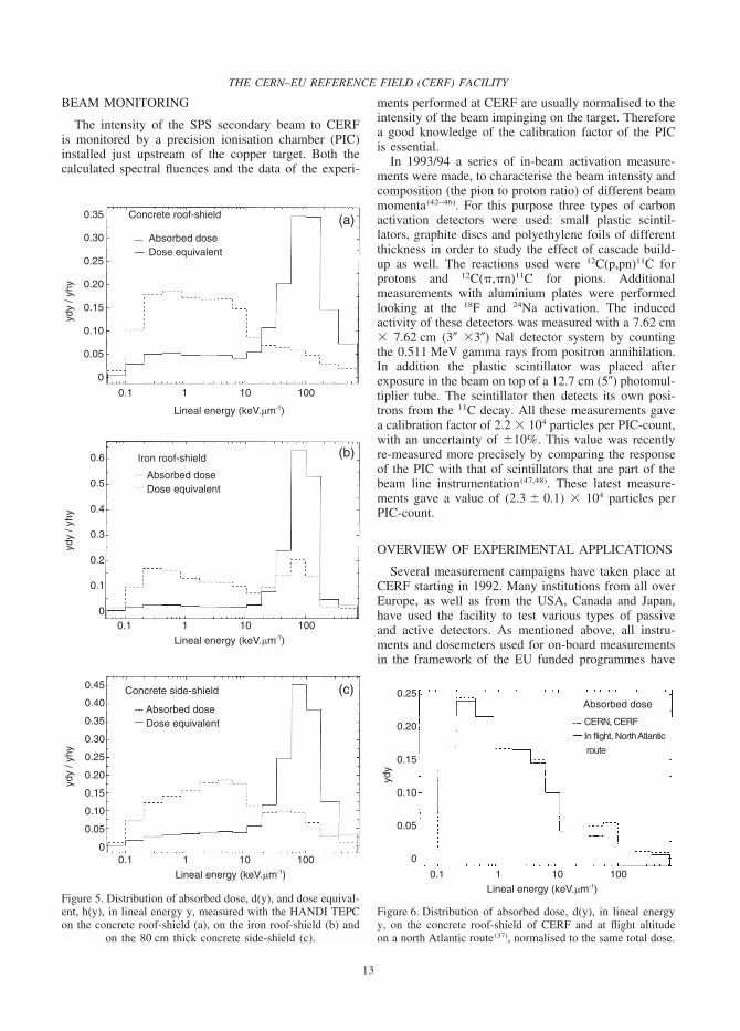
The reference values of neutron ambient dose equiv-alent, H*(10), on the concrete and iron roof-shields aregiven in Table 2 for a 120 GeV/c positive beam. Thevalues are obtained by folding the neutron spectral flu-ence calculated by FLUKA at the centre of each of the16 squares of the grid, 25 cm above the shield (i.e. atthe centre of a 50 � 50 � 50 cm3 air volume) with thefluence-to-ambient dose equivalent conversions coef-ficients of ICRP 74 (up to 19 MeV)(35) and of Ferrariand Pelliccioni (above 19 MeV)(36). The values aremapped according to the grid shown in Figure 3(b). Thestatistical uncertainties of the Monte Carlo calculationsare less than 2% for the concrete shield and less than1% for the iron shield. The values are normalised to oneunit of the beam monitor (PIC-count). The microdosi-metric spectra measured on the concrete and iron roof-shields as well as on the 80 cm thick concrete side-shield by the HANDI TEPC are shown in Figure 5. Thesimilarity of the absorbed dose distribution in linealenergy y on the concrete roof-shield and at flightaltitude(37) is shown in Figure 6.
MUON BACKGROUND
At the measurement sites on the concrete and ironroof-shields there is a significant low-LET backgroundradiation field. This background, which is timed to thepulsed structure of the beam, is not coming from inter-action of the beam in the copper target but is mainlydue to high-energy muons originating from pion decayin the beam line, with some contribution from hadronbeam losses upstream in the H6 or neighbouring beamlines. If not taken into account, this background appearsas an apparent non-linearity of a detector response whenmeasurements are performed at different intensities ofthe incident hadron beam. This concerns ionisationchambers, TEPC and other active devices that have con-siderable sensitivity to low-LET radiation. On the otherhand, there is no significant muon background at theside concrete shielded positions.
Various measurements(38–41) have shown that, first,
Table 2. Reference values of neutron ambient dose equivalent, H*(10), on the concrete and iron roof-shields, for a beamof positive particles with 120 GeV/c momentum (35% protons, 61% pions and 4% kaons) incident on the copper target,calculated by Monte Carlo. The values are mapped according to the grid shown in Figure 3(b). The statistical uncertaintiesare less than 2% for the calculations for the concrete shield and less than 1% for the iron shield. The H*(10) values arenormalised to one unit of the beam monitor (PIC-count), with one PIC-count � 2.2 � 104 hadrons impinging on the
target.
Neutron ambient dose equivalent, H*(10) (pSv per PIC-count)
Concrete roof-shield Iron roof-shield
216 254 253 207 1041 1286 1203 732225 270 270 222 1170 1490 1454 1002213 267 265 207 1238 1602 1596 1099185 223 221 182 1137 1493 1471 1005
the muons are also present with the H6 beam switchedoff. This means that the muon intensity is essentiallyindependent of the intensity of the hadron beam on thecopper target and thus cannot be normalised to the PIC-counts. Second, there is a strong gradient of the muonfluence when moving from the Saleve to the Jura sideof the facility (Figure 2), due to a large muon contri-bution from the neighbouring H8 beam line on theSaleve side. Third, there is a small contribution ofmuons coming from the H6 beam line. This additionalcomponent is however not originating from the H6 pro-duction target, which is seen under a big angle, butrather from the upstream collimators that are used tolimit the beam intensity and hence are a source of pen-etrating muons. For typical high intensity beam con-ditions, the muon background ranges from 3 to 12 pGyper PIC-count moving from the Saleve side to the Juraside of the concrete roof-shield. This should becompared with a total dose equivalent on the concreteroof-shield of typically 300 to 400 pSv/PIC-countrespectively, of which 50 to 75 pSv/PIC-count resultingfrom low-LET particles (�6 keV.�m�1).
The muon background is obviously more importantat low beam intensities(40). The ratio of low-LET to totaldose equivalent increases from a few per cent for beamintensities above about 2000 PIC-counts per SPS pulse,to about 10% at 1000 PIC-counts per pulse and up towell above 50% for low beam intensity of a few hun-dreds PIC-counts per pulse.
Since the muon background is mostly independent ofthe intensity in the H6 beam line but changes with fac-tors like beam composition (the pion fraction is a func-tion of beam momentum) and intensity in the neighbour-ing beam lines, it is not exactly reproducible from runto run. The background must be checked before eachexperiment with low-LET sensitive devices. Neverthe-less, the CERF mixed neutron, photon and muon fieldwas used to test, before its use on board aircraft, amethod of separating TEPC pulse heights for non-charged and charged particles using an active shieldingdetector developed by PTB(8).
THE CERN–EU REFERENCE FIELD (CERF) FACILITY
13
BEAM MONITORING
The intensity of the SPS secondary beam to CERFis monitored by a precision ionisation chamber (PIC)installed just upstream of the copper target. Both thecalculated spectral fluences and the data of the experi-
�"7�
�"7�
�"��
�"��
�"$�
�"$�
�"��
�
��������������� ���%
2*���*�%�%���(�����)�'�����
�"$ $ $� $��
;����������!��,3��"��$-
�%����� �
2*���*�%�%���(�����)�'�����
�"$ $ $� $��;����������!��,3��"��$-
�%����� �
�".
�"�
�"+
�"7
�"�
�"$
�
&���������� ���%
2*���*�%�%���(�����)�'�����
�"$ $ $� $��;����������!��,3��"��$-
�"+�
�"+�
�"7�
�"7�
�"��
�"��
�"$�
�"$�
�"��
�
�%����� �
,�-
,*-
,�-�����������%��� ���%
Figure 5. Distribution of absorbed dose, d(y), and dose equival-ent, h(y), in lineal energy y, measured with the HANDI TEPCon the concrete roof-shield (a), on the iron roof-shield (b) and
on the 80 cm thick concrete side-shield (c).
ments performed at CERF are usually normalised to theintensity of the beam impinging on the target. Thereforea good knowledge of the calibration factor of the PICis essential.
In 1993/94 a series of in-beam activation measure-ments were made, to characterise the beam intensity andcomposition (the pion to proton ratio) of different beammomenta(42–46). For this purpose three types of carbonactivation detectors were used: small plastic scintil-lators, graphite discs and polyethylene foils of differentthickness in order to study the effect of cascade build-up as well. The reactions used were 12C(p,pn)11C forprotons and 12C(�,�n)11C for pions. Additionalmeasurements with aluminium plates were performedlooking at the 18F and 24Na activation. The inducedactivity of these detectors was measured with a 7.62 cm� 7.62 cm (3� �3�) Nal detector system by countingthe 0.511 MeV gamma rays from positron annihilation.In addition the plastic scintillator was placed afterexposure in the beam on top of a 12.7 cm (5�) photomul-tiplier tube. The scintillator then detects its own posi-trons from the 11C decay. All these measurements gavea calibration factor of 2.2 � 104 particles per PIC-count,with an uncertainty of �10%. This value was recentlyre-measured more precisely by comparing the responseof the PIC with that of scintillators that are part of thebeam line instrumentation(47,48). These latest measure-ments gave a value of (2.3 � 0.1) � 104 particles perPIC-count.
OVERVIEW OF EXPERIMENTAL APPLICATIONS
Several measurement campaigns have taken place atCERF starting in 1992. Many institutions from all overEurope, as well as from the USA, Canada and Japan,have used the facility to test various types of passiveand active detectors. As mentioned above, all instru-ments and dosemeters used for on-board measurementsin the framework of the EU funded programmes have
�"��
�"��
�"$�
�"$�
�"��
�
2*���*�%�%���
����:����9&�����! �:����� �2������������
�%�
�"$ $ $� $��;����������!��,3��"��$-
Figure 6. Distribution of absorbed dose, d(y), in lineal energyy, on the concrete roof-shield of CERF and at flight altitudeon a north Atlantic route(37), normalised to the same total dose.

A. MITAROFF and M. SILARI
14
been periodically tested and calibrated at CERF(3). Inaddition, several other institutions have performed vari-ous types of measurements at the facility over the years.To show the range of applications of CERF, this sectiongives a (possibly non-exhaustive) overview of the mostimportant dosimetric applications for which the facilityhas been used. This overview groups, somehow arbi-trarily, the investigations in the following categories:test and intercomparison of either active instrumentationor passive devices, active and passive dosemeters usedfor individual monitoring, in-flight measurements basedon CERF calibration either on commercial flights or inspace, and radiobiological studies. A few representativeexperimental results, some previously unpublished, aregiven.
Active instrumentation
A first intercomparison of the response of dosemetersused in high-energy stray radiation fields was carriedout in 1992 at the ‘pre-CERF’ facility. At that time thefacility had not yet the present configuration. The beamused was 200 GeV/c positive hadrons (2/3 protons and1/3 positive pions) and the target assembly consisted ofan iron block 140 cm long, 50 cm wide and 30 cm high.Top shielding, where measurements were performed,was either 80 cm thick concrete or 60 cm thick iron.Measurements were also made in front of the accessdoor to check the dosemeter response in a softer field.The instruments tested were different TEPCs, conven-tional and extended range rem counters, a recombinationchamber type REM-2(41) (a cylindrical, parallel-plateionisation chamber with 25 tissue-equivalent electrodes,manufactured in Poland. It has a volume of 2000 cm3,mass of 6 kg and an effective wall thickness of2 g.cm�2; it is filled with a mixture of methane andnitrogen (5%) at a pressure of about 1 MPa), theCERBERUS (a multiple-detector system, developedat CERN, consisting of a rem ionisation chamber, atissue-equivalent ionisation chamber, an air-filled alu-minium chamber and a 11C activation detector), a set ofBonner spheres and NTA films(49).
Golnik and co-workers have investigated the appli-cation of recombination chambers in the determinationof microdosimetric data, based on the comparison ofsaturation curves measured for mixed radiation withthose for reference gamma radiation (137Cs). Measure-ments performed in the CERF field showed that the low-LET component predominates in the absorbed dose, onboth the concrete and iron roof-shields and equals 90%for the former and 73% for the latter. These values arein good agreement with the results of measurementswith the HANDI TEPC in use at CERN(50). The valuesof ambient dose equivalent rate obtained by differenttypes of recombination chambers compared well withthose from other devices(51). In particular, a REM-2recombination chamber was used to investigate the low-LET background radiation(41).
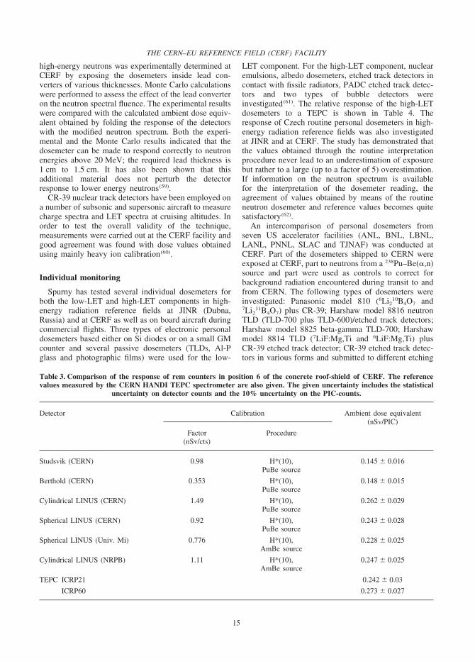
The responses of various types of rem counters werecompared on the concrete roof-shield in a dedicatedexperiment. Two of the instruments were of conven-tional design and four were cylindrical or spherical ver-sions of the LINUS. The results, given in Table 3together with values measured by the CERN HANDITEPC, showed a good agreement amongst the variousLINUS. The two conventional rem counters underesti-mated the total dose equivalent by about 40%, due totheir reduced response above 20 MeV. This result wasfound in perfect agreement with previous measurementswith high energy neutrons(30–32,52). The value of ambientdose equivalent for the several LINUS was also foundin remarkable agreement with that measured by theTEPC(53).
Lindborg and co-workers have developed the ‘Sievert-instrument’, a device consisting of two TEPCs withdiameter of 11.5 cm simulating mean chord lengths of2 �m, and electronics units for analysing the signalaccording to the variance–covariance method. Theinstrument is calibrated in H*(10) in a 137Cs field andits response to broad neutron fields was investigated atthe CERF facility. With the assumption that the LETdistribution in the atmosphere is reasonably well charac-terised by a combination of a CERF field and a low-LET field, the instruments can be used directly formeasurements on board(54–56).
First measurements of the response of high-sensitivityMOSFET devices to a simulated cosmic neutron fieldwere performed at CERF by Benson et al(57). A total of18 devices of different design were tested, some havingthe surface of the silicon wafer covered with layers ofpolyethylene of different thicknesses to promote (n,p)reactions with high energy neutrons and thus enhancethe response of the detector to the neutron componentof the radiation field. This preliminary investigation hasshown that, in their present form, these devices are tooinsensitive for cosmic neutron dosimetry. Alternativemethods to increase their sensitivity need be investi-gated.
Passive dosimetry
At CERF Spurny and Bottolier-Depois haveinvestigated three microdosimetry methods based ona TEPC, on chemically etched polyallyldiglycolcar-bonate (PADC) solid state nuclear track detectors andon bubble detectors. A LET spectrometer has beendeveloped based on PADC. The microdosimetric spec-tra determined on board aircraft and behind the shield-ing of high-energy particle accelerators were compared.The spectra obtained with the NAUSICAA TEPC andwith the PADC LET spectrometer agree well; their formis similar in the CERF reference field and on boardaircraft. Bubble detectors were tested at CERF and onboard aircraft, to verify their relative response withdifferent thresholds in different radiation fields(58).
The extension of the response of bubble detectors to
THE CERN–EU REFERENCE FIELD (CERF) FACILITY
15
high-energy neutrons was experimentally determined atCERF by exposing the dosemeters inside lead con-verters of various thicknesses. Monte Carlo calculationswere performed to assess the effect of the lead converteron the neutron spectral fluence. The experimental resultswere compared with the calculated ambient dose equiv-alent obtained by folding the response of the detectorswith the modified neutron spectrum. Both the experi-mental and the Monte Carlo results indicated that thedosemeter can be made to respond correctly to neutronenergies above 20 MeV; the required lead thickness is1 cm to 1.5 cm. It has also been shown that thisadditional material does not perturb the detectorresponse to lower energy neutrons(59).
CR-39 nuclear track detectors have been employed ona number of subsonic and supersonic aircraft to measurecharge spectra and LET spectra at cruising altitudes. Inorder to test the overall validity of the technique,measurements were carried out at the CERF facility andgood agreement was found with dose values obtainedusing mainly heavy ion calibration(60).
Individual monitoring
Spurny has tested several individual dosemeters forboth the low-LET and high-LET components in high-energy radiation reference fields at JINR (Dubna,Russia) and at CERF as well as on board aircraft duringcommercial flights. Three types of electronic personaldosemeters based either on Si diodes or on a small GMcounter and several passive dosemeters (TLDs, Al-Pglass and photographic films) were used for the low-
Table 3. Comparison of the response of rem counters in position 6 of the concrete roof-shield of CERF. The referencevalues measured by the CERN HANDI TEPC spectrometer are also given. The given uncertainty includes the statistical
uncertainty on detector counts and the 10% uncertainty on the PIC-counts.
Detector Calibration Ambient dose equivalent(nSv/PIC)
Factor Procedure(nSv/cts)
Studsvik (CERN) 0.98 H*(10), 0.145 � 0.016PuBe source
Berthold (CERN) 0.353 H*(10), 0.148 � 0.015PuBe source
Cylindrical LINUS (CERN) 1.49 H*(10), 0.262 � 0.029PuBe source
Spherical LINUS (CERN) 0.92 H*(10), 0.243 � 0.028PuBe source
Spherical LINUS (Univ. Mi) 0.776 H*(10), 0.228 � 0.025AmBe source
Cylindrical LINUS (NRPB) 1.11 H*(10), 0.247 � 0.025AmBe source
TEPC ICRP21 0.242 � 0.03
ICRP60 0.273 � 0.027
LET component. For the high-LET component, nuclearemulsions, albedo dosemeters, etched track detectors incontact with fissile radiators, PADC etched track detec-tors and two types of bubble detectors wereinvestigated(61). The relative response of the high-LETdosemeters to a TEPC is shown in Table 4. Theresponse of Czech routine personal dosemeters in high-energy radiation reference fields was also investigatedat JINR and at CERF. The study has demonstrated thatthe values obtained through the routine interpretationprocedure never lead to an underestimation of exposurebut rather to a large (up to a factor of 5) overestimation.If information on the neutron spectrum is availablefor the interpretation of the dosemeter reading, theagreement of values obtained by means of the routineneutron dosemeter and reference values becomes quitesatisfactory(62).
An intercomparison of personal dosemeters fromseven US accelerator facilities (ANL, BNL, LBNL,LANL, PNNL, SLAC and TJNAF) was conducted atCERF. Part of the dosemeters shipped to CERN wereexposed at CERF, part to neutrons from a 238Pu–Be(,n)source and part were used as controls to correct forbackground radiation encountered during transit to andfrom CERN. The following types of dosemeters wereinvestigated: Panasonic model 810 (6Li210B4O7 and7Li2
11B4O7) plus CR-39; Harshaw model 8816 neutronTLD (TLD-700 plus TLD-600)/etched track detectors;Harshaw model 8825 beta-gamma TLD-700; Harshawmodel 8814 TLD (7LiF:Mg,Ti and 6LiF:Mg,Ti) plusCR-39 etched track detector; CR-39 etched track detec-tors in various forms and submitted to different etching

A. MITAROFF and M. SILARI
16
procedures; Panasonic model UD-802 using lithiumtetraborate (LiBO4) or Li2B4O7:Cu and calcium sulphate(CaSO4) or CaSO4:Tm. The experiment showed that ifa field-specific calibration factor is used to correct thedose equivalent responses, the agreement with thereference dose equivalent is in the range 25 to 65%depending on dosemeter type(63).
A Japanese group has developed a real-time neutronpersonal dosemeter, which contains a fast and a slowneutron sensor. Both sensors are p-type silicon semicon-ductor detectors, the latter with a natural boron layerdeposited around an aluminium electrode to detect and Li ions from the 10B(n,) reaction. A thin polyethyl-ene radiator is in contact with the front surface of eachsensor to produce recoil protons. Field measurements ofthe performance of the device were carried out aroundseveral nuclear facilities (reactors, accelerators andnuclear fuel handling facilities) including CERF (bothon the concrete and iron roof-shields). The resultsshowed that the dosemeter is able to provide a readingof the neutron dose equivalent within a factor of 2 ofthe real value. The device also proved insensitive togamma rays up to dose rate of 1 Sv.h−1. The dosemeteris now commercially available from Fuji Electric Co.Ltd(64).
In-flight measurements based on CERF calibration
Measurements were performed on Concorde usingthe NRPB (UK) passive survey meter, which uses 30to 40 dosemeters for both the neutron and non-neutroncomponent of the field. The survey meter uses dosemet-ers from the NRPB routine personal dosimetry services(TLDs for the non-neutron component and PADCetched track detectors for the neutron component). Acalibration factor was determined for the neutron flu-ence response of the passive survey meter for the CERFconcrete roof-shield. Both batch and sheet dependenceof this calibration factor have been investigated. It was
Table 4. Response of individual dosemeters to the high-LET component of CERF(61) relative to a TEPC.
Dosemeter Relative response of dosemeter to TEPC
Concrete roof-shield Iron roof-shield
6LiF in albedo PGP DIN 0.10 � 0.02 0.40 � 0.09Nuclear emulsion NTA 3.70 � 0.90 1.50 � 0.30Etched track detector with 2.90 � 0.50 1.60 � 0.20
fissile radiatorsPADC 0.35 � 0.06 0.26 � 0.04Etched track detectorBDND BD 100R 0.57 � 0.09 1.35 � 0.18BDND PND 0.63 � 0.11 1.49 � 0.21SDD 100 0.59 � 0.11 0.66 � 0.09SDD 1000 0.77 � 0.15 0.27 � 0.06SDD 6000 1.14 � 0.20 0.24 � 0.05
concluded that a sheet and batch calibration factor canbe applied, but a periodic check should be made. Theresults are given in Figure 7. It is assumed that the flu-ence response measured for the CERF spectrum can becorrected by the ratio of the predicted responses of thepassive survey meter for the calculated neutron spec-trum in the atmosphere by Heinrich et al(26) to that cal-culated for CERF. For the PADC etched track detectors,the use of the CERF calibration is considered to give agood estimate, within 20 or 30% systematic uncertainty,of effective dose or ambient dose equivalent for theneutron component of the cosmic radiation field inaircraft(12).
As part of a continuing assessment of the cosmic radi-ation exposure of Canadian based aircrew, a TEPC wasused to take dosimetric measurements on board 64
7�
7+
77
7�
7$
7�
�8
�6
�#
�.
��
$�<
$�<
9���
��������
���
����3��������
����
������
� �,�$�
�.-
2����$886
/��$886
/��$888
2!��$888
=������
/������
����*�������%���
Figure 7. Calibration measurements of the NRPB passive sur-vey meter, PADC neutron detectors at CERF (April 1998 toJuly 2000)(12). Small symbols, individual sheet results. Largesymbol, mean for that measurement ±SEM. (– – –) overall
mean 30.6 ± 0.3 (SEM).

THE CERN–EU REFERENCE FIELD (CERF) FACILITY
17
flights from September 1998 to October 1999. In con-junction with the in-flight measurements, the operationof the TEPC was verified using several commonradioisotopic sources and in the CERF neutron field.The values of various microdosimetric quantitiesobtained from several terrestrial sources, including thoseobtained from the CERF spectrum, provided a usefulcomparison to the values obtained from the radiationfield at jet altitudes(65).
A diverse array of both passive and active instru-ments, to cover all radiation components of the field ataviation altitudes, was employed in the Italian nationalsurvey of aircrew exposure(10). The detectors used werethe LINUS; the ANPA stack, a passive multidetectorstack including bubble detectors (for low-energyneutrons), bismuth-fission track detectors (for high-energy neutrons), cellulose nitrate (LR-115 fromKodak) and polycarbonate track detectors for high-Zparticles, and various TLDs (including the hypersensi-tive Chinese lithium fluoride GR-200) for the low-LETcomponent; the DIAS stack consisting of 20 sheets ofCR-39 used to determine the fluence and type ofcharged particles as well as their LET; TEPC; PADC(CR-39); a high-pressure ionisation chamber Reuter–Stokes type RSS-112 (based on a spherical stainlesssteel ionisation chamber filled with ultra-pure argon gasunder high pressure). All these dosimetric systems haveprovided consistent results when exposed together atCERF(66). An example of the agreement obtainedbetween the range of instruments employed is shown inTable 5(15).
Measurements related to space programmes
CERF has also been used to test instrumentationflown in space. The response of a space shuttle TEPCwas investigated at the facility and compared to otherdosimetric devices(67). When exposed to high-energyneutrons, the dose equivalent response was found nearlythe same as that of the HANDI TEPC of CERN. Overthe LET range produced primarily by charged particles(�20 keV.�m−1) the response of the TEPC is nearlyidentical to that of the DOSTEL telescope, consistingof two 300 �m thick Si detectors, developed at the Uni-versity of Kiel(68).
Table 5. Measured and calculated ambient dose equivalentrates at CERF relative to the CERN HANDI TEPC (high-
let component �6 keV.�m�1)(15).
FLUKA calculated/CERN TEPC 0.91 � 0.07*USAAR HANDI/CERN TEPC 0.88 and 1.02ANPA stack/CERN TEPC 0.95 � 0.1NRPB etched track detectors 1.2 � 0.1(predicted)/CERN TEPCDIAS etched track detectors/CERN 1.18 � 0.12TEPC
*Average over all 16 concrete roof-shield locations
A new active personal neutron dosemeter developedat PTB for use in the space station MIR and the spaceshuttle, based on silicon diodes, shows improved sensi-tivity to neutrons, rejects charged particles by anticoin-cidence and, in addition, gives information on theneutron spectrum. It consists of a stack of silicon detec-tors sandwiched between layers acting as neutron con-verters, moderators and absorbers. A response matrixhas been determined by measurements in monoenergeticneutron reference fields. The first results of measure-ments at CERF showed good agreement with energydistributions calculated by the FLUKA code(69). Theabove active device was further developed for measur-ing the energy and directional distribution of neutronfluence in fields of broad energy spectra and with a highbackground of photon and muon radiation. Six detectorcapsules were mounted on a 30 cm diameter polyethyl-ene sphere, each of them containing four silicon detec-tors with different converters and shields. The energyand directional distribution of the fluence is recon-structed from the pulse height spectra and from theresponse function determined with monoenergeticneutron fields. The dose equivalent measured with thespectrometer agrees within 25% of the reference value.The results show that this directional spectrometerprovides reasonable results in fields with wide energydistributions, even in the case of intense low-LET back-ground as in CERF(70,71).
Other applications
A radiobiological investigation was also conducted atCERF, in spite of the lack of supporting structure atCERN for this type of application. Heimers has deter-mined the RBE of a mixed neutron–gamma simulatedcosmic radiation field and its high-LET component, onthe induction of chromosome aberrations in human lym-phocytes. The results of this preliminary investigationshowed a high RBE of cosmic radiation and its neutroncomponent in comparison with 60Co gamma radi-ation — up to 64, and up to 113 when calculating onlythe high-LET component(72). As these results raisedsome debate, there are plans to repeat the experiment inthe course of one of the CERF runs of 2002.
Other experimental results obtained at CERF in thefield of neutron spectrometry and dosimetry are reportedin the literature(73–80). It is also worth mentioning that,although most of the beam time was dedicated to testdosimetric instrumentation, the facility has also beenexploited for other uses, such as verifying the effect ofradiation on computer memories(81), testing prototypesof a beam loss monitor for the future CERN LargeHadron Collider (LHC)(82) and testing detector compo-nents for the upcoming LHC experiments(83).
LATEST DEVELOPMENTS
In a space station in low-earth orbit neutrons make
A. MITAROFF and M. SILARI
18
an important contribution to the personal doseequivalent(84). Most of the neutrons inside the stationresult from nuclear interactions of the charged particles(mainly galactic protons and protons trapped by theearth’s magnetic field) with the wall of the vessel. Aplot of E�E against log(E), where �E is the neutronfluence, shows peak intensities at about 1 MeV and100 MeV, while for protons the peaks show at about100 MeV (trapped proton source) and in the GeV region(galactic proton source). In fact, as mentioned in theprevious section, for the evaluation of dosemeters usedin space the calibration value determined at CERF was
&����� ���%
���������� ���%
������!���!���
0��
���!��
2����
Figure 8. Simplified spherical geometry used in the preliminary calculations for the upgrade of the CERF facility to reproducethe radiation field in a space vessel.
$�+
$�7
$��
$�
$
$��$
$���
$��7
$��+
(�������������������,���
��"��
��-
�������������������
��������%��������>��7
$��+
�
�$�
��
�
�
$��.
�
�
$��#
�� �,�
��-
$��7
�
�
�
�
�����
������� ����
���������
=���
������
�"�$ �"$ $ $� $������!��?���@
�"$ �"� �"� $ � � $� �� �� $�� ���
����!��,���-
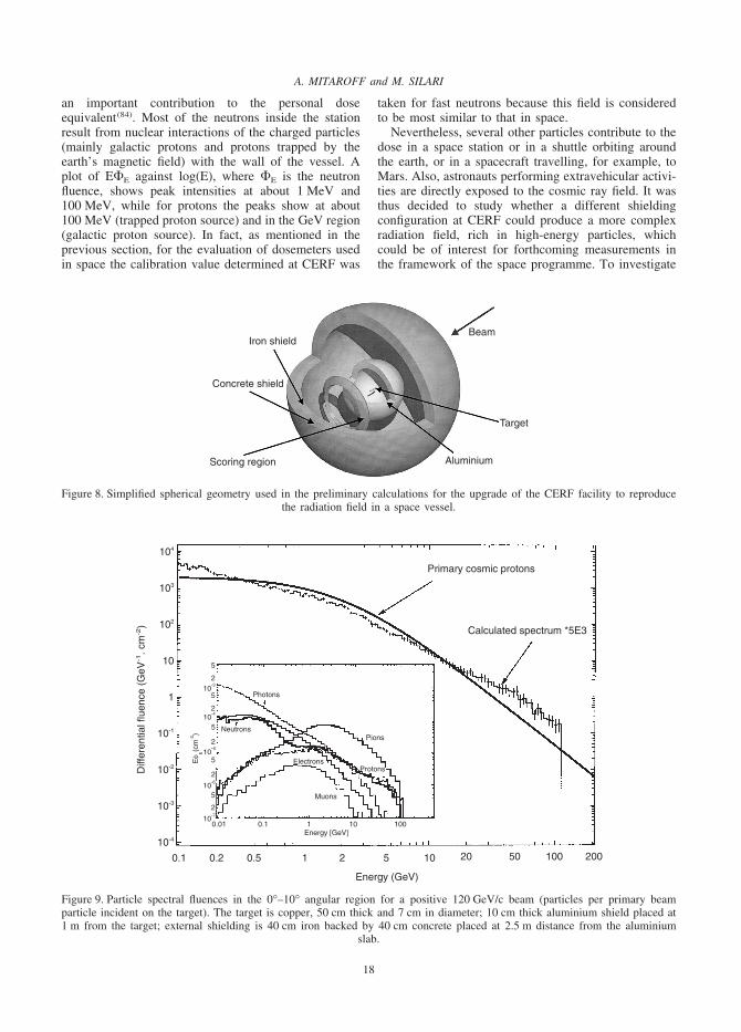
Figure 9. Particle spectral fluences in the 0°–10° angular region for a positive 120 GeV/c beam (particles per primary beamparticle incident on the target). The target is copper, 50 cm thick and 7 cm in diameter; 10 cm thick aluminium shield placed at1 m from the target; external shielding is 40 cm iron backed by 40 cm concrete placed at 2.5 m distance from the aluminium
slab.
taken for fast neutrons because this field is consideredto be most similar to that in space.
Nevertheless, several other particles contribute to thedose in a space station or in a shuttle orbiting aroundthe earth, or in a spacecraft travelling, for example, toMars. Also, astronauts performing extravehicular activi-ties are directly exposed to the cosmic ray field. It wasthus decided to study whether a different shieldingconfiguration at CERF could produce a more complexradiation field, rich in high-energy particles, whichcould be of interest for forthcoming measurements inthe framework of the space programme. To investigate

THE CERN–EU REFERENCE FIELD (CERF) FACILITY
19
this possibility, preliminary Monte Carlo simulationswere performed with the FLUKA code(22–25) in a simpli-fied spherical geometry (Figure 8). The aim was tounderstand if a given target/shielding combination andangular scoring region would indicate a promising situ-ation which could subsequently be investigated morethoroughly by modelling the complete facility. Calcu-lations were performed for the ‘standard’ 50 cm thick,7 cm diameter copper target as well as for smaller tar-gets. The study aimed at producing a radiation fieldmainly rich in high-energy protons similar to that foundin the stratosphere(85) or high-energy neutrons and othersecondary particles as found inside the space station ora spacecraft(86).
The target was at the centre of a spherical shield, withscoring done in conical regions 10° wide (0° to 90°).Neutrons, protons, pions, muons, photons and electronswere scored. A 10 cm thick aluminium shield wasplaced at 1 m distance from the target. An additionallayer of material acting as back shield (40 cm ironbacked by 40 cm concrete) was placed at 2.5 m distancefrom the aluminium. The particle spectra in the forwarddirection (0° to 10° angular region) are shown in Figure9. One should note, in particular, that the high-energycomponent (above 100 MeV) of the proton spectrum issimilar to the energy spectrum of cosmic ray protons(87).Also, the neutron energy distribution extends up toabout 100 GeV rather than the few hundreds MeV ofthe present CERF configuration on the concrete roof-shield. The simulations showed that the pion componentdecreases with respect to neutrons with increasing alu-minium thickness and increasing emission angle.
The influence of primary beam momentum on thesecondary particles produced was investigated in therange 40–400 GeV/c. The simulations have shown thatthe spectral shape and the secondary particle compo-sition do not change much with beam momentum, and
REFERENCES
1. International Commission on Radiological Protection. 1990 Recommendations of the International Commission on RadiologicalProtection. ICRP Publication 60 (Oxford: Pergamon Press) (1990).
2. Council Directive 96/29/Euratom of 13 May 1996. Laying Down Basic Safety Standards for the Protection of the Health ofWorkers and the General Public against the Dangers Arising from Ionizing Radiation. Official Journal of the EuropeanCommunities L159, Volume 39, 1–114 (29 June 1996).
3. Study of Radiation Fields and Dosimetry at Aviation Altitudes. EU contract number F14P-CT950011, Final report, January1996-June 1999, Report DIAS 99-9-1, (Dublin Institute for Advanced Studies, Dublin, Ireland) (1999).
4. Beck, P., Schrewe, U., O’Brien, K. and Ambrosi, P. ACREM, Air Crew Radiation Exposure Monitoring. Report OEFZS-G-0008, (Austrian Research Centres Seibersdorf) (November 1999).
5. Bartlett, D. T., Grillmaier, R., Heinrich, W., Lindborg, L., O’Sullivan, D., Schraube, H., Silari, M. and Tommasino, L. TheCosmic Radiation Exposure of Aircraft Crew. In: Proc. Conf. 11th Inter. Congress of Radiation Research, Dublin (Ireland),18–23 July 1999, Radiat. Res., 2: Congress Proceedings, Eds M. Moriarty, C. Mothersill, C. Seymour, M. Edington, J. F.Ward, and R. J. M. Fry, Allen Press, Inc., 719–723 (2000).
6. Menzel, H.-G., O’Sullivan, D., Beck, P. and Bartlett, D. European Measurements of Aircraft Crew Exposure to CosmicRadiation. Health Phys. 79, 563–567 (2000).
7. European Radiation Dosimetry Group. Exposure of Air Crew to Cosmic Radiation. EURADOS Report 1996–01, Eds I. R.McAulay, D. T. Bartlett, G. Dietze, H. G. Menzel, K. Schnuer, and U. J. Schrewe (1996).
8. Schrewe, U. J. Global Measurements of the Radiation Exposure of Civil Air Crew from 1997 to 1999. Radiat. Prot. Dosim.91, 347–364 (2000).
only the absolute fluence per beam particle on targetincreases with increasing momentum. With increasingemission angle the neutron component becomes moreand more dominant over the other particles.
CONCLUSIONS
The calibration of instruments and dosemeters atCERF is expected to continue to play an important rolein the fourth EU funded programme on the investigationof radiation fields and dosimetry at aviation altitudes.There is also increasing interest by many research insti-tutions outside the EU collaboration in using the facility,including measurements in the framework of the spaceprogramme. Promising Monte Carlo results have beenobtained in view of extending the range of particle spec-tra provided at CERF. These preliminary results willhave to be confirmed by more accurate calculations.
ACKNOWLEDGEMENTS
The operation of CERF is partially supported by theEuropean Commission, Directorate General XII, con-tracts no. F13P-CT92-0026 (1992–1995), F14P-CT95–0011 (1996–1999) and FIGM-CT-2000–00068 (thepresent contract). A Fasso, M. Hofert, T. Otto, G. R.Stevenson and L. Ulrici have contributed substantiallyto the set-up, start-up and operation of the facility overrecent years. Early Monte Carlo calculations were per-formed by G. R. Stevenson, the most recent ones by A.Ferrari, E. Nava and T. Rancati. In particular the authorswish to thank A. Ferrari for many useful discussionsand T. Rancati for providing the data of Table 2. Figure1 was taken from Reference 3, for which the authorswish to thank H. Schraube and D. O’Sullivan. They alsowish to thank D. Bartlett for providing them with thelatest results of the NRPC PADC calibration appearingin Figure 7.

A. MITAROFF and M. SILARI
20
9. Lewis, B. J., Tume, P., Bennet, L. G. I., Pierre, M., Green, A. R., Cousins, T., Hoffarth, B. E., Jones, T. A. and Brisson,J. R. Cosmic Radiation Exposure on Canadian-based Commercial Airline Routes. Radiat. Prot. Dosim. 86, 7–24 (1999).
10. Curzio, G., Grillmaier, R. E., O’Sullivan, D., Pelliccioni, M., Piermattei, S. and Tommasino, L. The Italian National Surveyof Aircrew Exposure: II. On-board Measurements and Results. Radiat. Prot. Dosim. 93, 125–133 (2001).
11. Townsend, L. W., Ed. Proc. 34th Annual Meeting of the National Council on Radiation Protection and Measurements:Cosmic Radiation Exposure of Airlines Crews, Passengers and Astronauts. Health Phys. 79, 470–613 (2000).
12. Bartlett, D. T., Hager, L. G., Irvine, D. and Bagshaw, M. Measurements on Concorde of the Cosmic Radiation Field atAviation Altitudes. Radiat. Prot. Dosim. 91, 365–376 (2000).
13. Beaujean, R., Kopp, J. and Reitz, G. Radiation Exposure in Civil Aircraft. Radiat. Prot. Dosim. 85, 287–290 (1999).14. Alberts, W. G., Alevra, A. V., Ferrari, A., Otto, T., Schrewe, U. J. and Silari, M. Calibration Problems, Calibration Pro-
cedures and Reference Fields for Dosimetry in Flight Altitudes. Radiat. Prot. Dosim. 86, 289–295 (1999).15. O’Sullivan, D., Bartlett, D., Grillmaier, R., Heinrich, W., Lindborg, L., Schraube, H., Silari, M., Tommasino, L. and Zhou
D. Investigation of Radiation Fields at Aircraft Altitudes. Radiat. Prot. Dosim. 92, 195–198 (2000).16. Russ, J. S., Stevenson, G. R., Fasso, A., Nielsen, M. C., Furetta, C., Rancoita, P. G. and Vismara, L. Low-energy Neutron
Measurements in an Iron Calorimeter Structure Irradiated by 200 GeV/c Hadrons. CERN Divisional Report TIS-RP/89–02 (1989).
17. Fasso, A., Stevenson, G. R., Bruzzi, M., Furetta, C., Rancoita, P. G., Giubellino, P., Steni, R. and Russ, J. S. Measurementsof Low-energy Neutrons in an Iron Calorimeter Structure Irradiated by 24 GeV/c Hadrons. CERN Divisional Report TIS-RP/90–19 (1990).
18. Stevenson, G. R., Fasso, A., Furetta, C., Rancoita, P. G., Giubellino, P., Russ, J. S. and Bertrand, C. Measurements of Low-Energy Neutrons in a Lead Calorimeter Structure Irradiated by 200 GeV/c Hadrons. CERN Divisional Report TIS-RP/91–11 (1991).
19. Fasso, A., Ferrari, A., Ranft, J., Sala, P. R., Stevenson, G. R. and Zazula, J. M. A Comparison of FLUKA Simulations withMeasurements of Fluence and Dose in Calorimeter Structures. Nucl. Instrum. Meth. A 332, 459–468 (1993).
20. Hofert, M. and Stevenson, G. R. The CERN-CEC High-energy Reference Field Facility. In: Proc. 8th International Conferenceon Radiation Shielding, Arlington, Texas, April 1994. (American Nuclear Society), pp. 635–642 (1994).
21. Birattari, C., Ferrari, A., Hofert, M., Otto, T., Rancati, T. and Silari, M. Recent Results at the CERN-EC High-energyReference Field Facility. In: Proc. Satif-3. Shielding Aspects of Accelerators, Targets and Irradiation Facilities, Sendai, Japan,12–13 May 1997. NEA/OECD, pp. 219–234 (1998).
22. Fasso, A., Ferrari, A., Ranft, J. and Sala, P. R. FLUKA: Present Status and Future Developments. In: Proc. IV Int. Conf.on Calorimetry in High Energy Physics, La Biodola, Italy, 21–26 September 1993, Eds. A. Menzione and A. Scribano,(Singapore: World Scientific), pp. 493–502 (1994).
23. Fasso, A., Ferrari, A., Ranft, J. and Sala, P. R. New Developments in FLUKA Modelling of Hadronic and EM Interactions.In: Proc. on Simulating Accelerator Radiation Environments (SARE3), Tsukuba, Japan, May 1997. Ed. H. Hirayama, KEKProc. 97(5), 32–44 (1997).
24. Fasso, A., Ferrari, A., Ranft J. and Sala, P. R. An Update about FLUKA. In: Proc. 2nd Workshop on Simulating AcceleratorRadiation Environments, CERN, Geneva, Switzerland, 9–11 October 1995, Ed. G. R. Stevenson, CERN Divisional ReportTIS-RP/97–05, 158–170 (1997).
25. Ferrari, A. and Sala, P. R. The Physics of High Energy Reactions. In: Proc. Workshop on Nuclear Reaction Data and NuclearReactors Physics, Design and Safety, International Centre for Theoretical Physics, Miramare-Trieste, Italy, 15 April–17 May1996, Ed. A. Gandini and G. Reffo, Vol 2, World Scientific, 424–532 (1998).
26. Heinrich, W., Roesler, S. and Schraube, H. Physics of Cosmic Radiation fields. Radiat. Prot. Dosim. 86, 253–258 (1999).27. Bartlett, D. T., Tanner, R. J. and Hager, L. G. The High Energy Neutron Response Characteristics of a Passive Survey
Instrument for the Determination of Cosmic Radiation Fields in Aircraft. In: Proc. 13th Int. Conf. on Solid State Dosimetry,Athens, Greece, 9–13 July 2001, Radiat. Prot. Dosim. 100(1–4), 519–524 (2002).
28. Birattari, C., De Ponti, E., Esposito, A., Ferrari, A., Magugliani, M., Pelliccioni, M., Rancati, T. and Silari, M. Measurementsand Simulations in High-energy Neutron Fields. In: Proc. Satif-2 Shielding Aspects of Accelerators, Targets and IrradiationFacilities, Geneva, Switzerland, October 1995. OECD/NEA, pp. 171–197 (1996).
29. Birattari, C., Ferrari, A., Nuccetelli, C., Pelliccioni, M. and Silari, M. An Extended Range Neutron Rem Counter. Nucl.Instrum. Methods A 297, 250–257 (1990).
30. Birattari, C., Esposito, A., Ferrari, A., Pelliccioni, M. and Silari, M. A Neutron Survey Meter With Sensitivity Extended upto 400 MeV. Radiat. Prot. Dosim. 44, 193–197 (1992).
31. Birattari, C., Esposito, A., Ferrari, A., Pelliccioni, M. and Silari, M. Calibration of the Neutron Rem Counter LINUS in theEnergy Range from Thermal to 19 MeV. Nucl. Instrum. Methods A 324, 232–238 (1993).
32. Birattari, C., Esposito, A., Ferrari, A., Pelliccioni, M., Rancati, T. and Silari, M. The Extended Range Neutron Rem Counter‘LINUS’: Overview and Latest Developments. Radiat. Prot. Dosim. 76, 135–148 (1998).
33. Mitaroff, A. and Silari, M. Improving the High Energy Response of a Bonner Sphere Spectrometer. CERN Internal ReportTIS-RP/IR/99–27 (1999).
34. Birattari, C., Cappellaro, P., Mitaroff, A. and Silari, M. Development of an Extended Range Bonner Sphere Spectrometer.

THE CERN–EU REFERENCE FIELD (CERF) FACILITY
21
In: Proc. Advanced Monte Carlo for Radiation Physics, Particle Transport Simulation and Applications, Lisbon, Portugal,23–26 October 2000, Eds A. Kling, F. Barao, M. Nakagawa, L. Tavora, and P. Vaz, (Berlin: Springer) 1157–1162 (2001).
35. International Commission on Radiological Protection. Conversion Coefficients for use in Radiological Protection againstExternal Radiation. Publication 74 (Oxford: Pergamon Press) (1996).
36. Ferrari, A. and Pelliccioni, M. Fluence to Dose Equivalent Conversion Data and Effective Quality Factors for High EnergyNeutrons. Radiat. Prot. Dosim. 76, 215–224 (1998).
37. Grillmaier, R. E., Gerdung, S. and Lim, T. Private communication.38. Hofert, M., Sannikov, A. V. and Stevenson, G. R. Muon Background Subtraction from HANDI-TEPC Measurements Data
(CERN-CEC May 1994 experiment). CERN Internal Report TIS-RP/IR/94–13 (1994).39. Fasso, A., Hofert, M. and Nielsen, M. Muon Measurements at the CERN-CEC High Energy Reference Field Facility during
the H6M95 Run. CERN Internal Report TIS-RP/IR/95–27 (1995).40. Otto, T. and Silari, M. The July/August 1996 run at the CERN-CEC Reference Facility. CERN Technical Memorandum
TIS-RP/TM/96–25 (1996).41. Golnik, N., Silari, M. and Otto, T. On the Use of a Recombination Chamber for Radiation Measurements in CERN-EU High
Energy Reference Radiation Fields. Radiat. Prot. Dosim. 86, 175–179 (1999).42. Carlsson, A., Hooper, M. C., Liu, J., Roesler, S., Stevenson, G. R. SL-RP Measurements during the July 1993 CERN-CEC
Experiments. CERN Technical Memorandum TIS-RP/TM/93–32 (1993).43. Hooper, M. C., Raffnsœ, C., Stevenson, G. R. Beam Monitoring in the May 1993 CERN-CEC Experiment. CERN Technical
Memorandum TIS-RP/TM/93–22 (1993).44. Liu, J., Roesler, S., Stevenson, G. R. Carbon-11 in Beam Measurements during the September 1993 CERN-CEC Experiments.
CERN Technical Memorandum TIS-RP/TM/93–43 (1993).45. Roesler, S., Stevenson, G. R. Carbon-11 Measurements during the May 1994 H6 runs. CERN Technical Memorandum TIS-
RP/TM/94–10 (1994).46. Stevenson, G. R., Liu, J., O’Brian, K., Williams, J. Beam Intensity Measurements Using 11C Activation for the CERN-CEC
Experiments. CERN Technical Memorandum TIS-RP/TM/94–15 (1994).47. Elsener, K., Heilmann, M., Silari, M. Verification of the Calibration Factor of the CERF Beam Monitor. CERN Technical
Memorandum TIS-RP/TM/98–22 (1998).48. Gschwendtner, E., Mitaroff, A., Ulrici, L. A New Calibration of the PIC Monitor in H6. CERN Internal Report TIS-
RP/IR/2000–09 (2000).49. Birattari, C., Esposito, A., Fasso, A., Ferrari, A., Festag, J. G., Hofert, M., Nielsen, M., Pelliccioni, M., Raffnsøe, C., Schmidt,
P. and Silari, M. Intercomparison of the Response of Dosemeters used in High Energy Stray Radiation Fields. Radiat. Prot.Dosim. 51, 87–94 (1994).
50. Golnik, N. Microdosimetry using a Recombination Chamber: Method and Applications. Radiat. Prot. Dosim. 61, 125–128(1995).
51. Rusinowski, Z. and Golnik, N. Performance Tests of the IAE Dose Equivalent Meter in Radiation Field of High EnergyCalibration Facility at SPS-CERN. Nucl. Instrum. Methods A 408, 600–602 (1998).
52. Agosteo, A., Birattari, C., Foglio Para, A., Nava, E., Silari, M. and Ulrici, L. Neutron Measurements in the Stray FieldProduced by 158 GeV c�1 per Nucleon Lead Ion Beams. Health Phys. 75, 619–629 (1998).
53. Silari, M. and Ulrici, L. Intercomparison of Rem Counters in the CERF Neutron Field. CERN Technical Memorandum TIS-RP/TM/98–23 (1998).
54. Kyllonen, J.-E., Lindborg L. and Samuelson, G. Paired TEPCs for Variance Measurements. In: Microdosimetry: an Interdisci-plinary Approach. Eds D., Goodhead, P. O’Neill, and H. G. Menzel, Cambridge: The Royal Society of Chemistry, Specialpublication No. 204 (1997).
55. Kyllonen, J.-E., Lindborg L. and Samuelson, G. The Response of the Sievert-instrument in Neutron Beams up to 180 MeV.Radiat. Prot. Dosim. 94, 227–232 (2001).
56. Kyllonen, J.-E., Lindborg L. and Samuelson, G. Cosmic Radiation Measurements On-board Aircraft with the VarianceMethod. Radiat. Prot. Dosim. 93, 197–205 (2001).
57. Benson, C., Joyce, M. J., O’Connell, B. and Silvie, J. Neutron Detection at the Extremes of Sensitivity in the CosmicEnvironment. IEEE Trans. Nucl. Sci. NS-47, 2417–2422 (2000).
58. Spurny, F. and Bottolier-Depois, J.-F. Microdosimetry of Environmental Radiation Fields. In: Eds. C. Baumstark-Khan et al ,Fundamentals for the Assessment of Risks from Environmental Radiation, Netherlands, Kluwer Academic Publishers, pp.497–502 (1999).
59. Agosteo, S., Silari, M. and Ulrici, L. Improved Response of Bubble Detectors to High Energy Neutrons. Radiat. Prot. Dosim.88, 149–155 (2000).
60. O’Sullivan, D., Zhou, D., Heinrich, W., Roesler, S., Donnelly, J., Keegan, R., Flood, E. and Tommasino, L. Cosmic Raysand Dosimetry at Aviation Altitudes. Radiat. Meas. 31, 579–584 (1999).
61. Spurny, F. Individual Dosimetry for High-energy Radiation Fields. Radiat. Prot. Dosim. 85, 15–20 (1999).62. Spurny, F., Trousil, J. and Studena, J. Response of Czech Routine Personal Dosemeters in High Energy Radiation Reference
Fields. Radiat. Prot. Dosim. 71, 181–185 (1997).

A. MITAROFF and M. SILARI
22
63. Stewart, R. D., McDonald, J. C., Otto, T. and Loesch, R. M. Fourth Intercomparison of Personal Dosemeters Used in theDepartment of Energy Accelerator Facilities. Radiat. Prot. Dosim. 87, 77–86 (2000).
64. Sasaki, M., Nakamura, T., Tsujimura, N., Ueda, O. and Suzuki, T. Development and Characterisation of a Real-time PersonalNeutron Dosemeter with Two Silicon Detectors. Nucl. Instrum. Methods A 418, 465–475 (1998).
65. McCall, M. J., Green, A. R., Lewis, B. J., Bennet, L. G. I., Pierre, M., Schrewe, U., O’Brien, K. and Feldsberger, E.Canadian-based Aircrew exposure from Cosmic Radiation on Commercial Airline Routes. In: Proc. 21st Ann. Conf. of theCanadian Nuclear Society, Toronto, Ontario, Canada, 11–14 June, 2000. ISBN 0-919784-66-6 (2000).
66. Curzio, G., Grillmaier, R. E., O’Sullivan, D., Pelliccioni, M., Piermattei, S. and Tommasino, L. Italian National Survey ofAircrew Exposure: I. Characterisation of Advanced Instrumentation. Radiat. Prot. Dosim. 93, 115–123 (2001).
67. Badhwar, G. D., Robbins, D. E., Gibbons, F. and Braby, L. A. Response of a Tissue Equivalent Proportional Counter toNeutrons. Radiat. Meas. (in press) (2002).
68. Beaujean, R., Kopp, J. and Reitz, G. Active Dosimetry on Recent Space Flights. Radiat. Prot. Dosim. 85, 223–226 (1999).69. Luszik-Bhadra, M., Matzke, M., Otto, T., Reitz, G. and Schuhmacher, H. Personal Neutron Dosimetry in the Space Station
MIR and the Space Shuttle. Radiat. Meas. 31 425–430 (1999).70. Luszik-Bhadra, M., Matzke, M. and Schuhmacher, H. Development of Personal Neutron Dosemeters at the PTB and First
Measurements in the Space Station MIR. Radiat. Meas. 33, 305–312 (2001).71. Luszik-Bhadra, M., d’Errico, F., Hecker, O. and Matzke, M. A Wide-range Direction Neutron Spectrometer. Nucl. Instrum.
Methods A 476, 291–297 (2002).72. Heimers, A. Cytogenetic Analysis in Human Lymphocytes after Exposure to Simulated Cosmic Radiation which Reflects the
Inflight Radiation Environment. Int. J. Radiat. Biol. 75, 691–698 (1999).73. Alevra, A. V., Klein, H. and Schrewe, U. J. Measurements with the PTB Bonner Sphere Spectrometer in High-energy Neutron
Calibration Fields at CERN. PTB-Bericht N-22 (1994).74. Dinter, H. and Tesch, K. Neutron Spectra behind the Shielding of a High Energy Proton Accelerator: Measurements and
Calculations. Radiat. Prot. Dosim. 63, 175–180 (1996).75. Spurny, F. Dosimetry of Neutrons and High Energy Particles with Nuclear Track Detectors. Radiat. Meas. 25, 429–436
(1995).76. Bottolier-Depois, J. F., Plawinski, L., Spurny, F. and Mazal, A. Microdosimetric Investigations in Realistic Fields. Radiat.
Prot. Dosim. 70, 203–206 (1997).77. Lim, T., Bottolier-Depois, J. F., Festag, J. G., Golnik, N., Grillmaier, R. E., Hofert, M. and Lindborg, L. Tissue-equivalent
Proportional Counters in a High-energy Neutron Field at CERN. In: Proc. Int. Conf. on Neutrons in Research and Industry,Crete (Greece), 9–15 June 1996, Ed. Vourvopoulos, SPIE 2867, 300–305 (1997).
78. Jozefowicz, K., Burgkhardt, B., Vilgis, M. and Piesch, E. Polycarbonate Track Detectors with a Flat Energy Response forthe Measurement of High Energy Neutrons at Accelerators and Airflight Altitudes. Radiat. Prot. Dosim. 70, 143–148 (1997).
79. Mares, V., Sannikov, A. and Schraube, H. The Response Functions of a He-3 Bonner Spectrometer and their ExperimentalVerification in High Energy Neutron Fields. In: Proc. Conf. Satif-3, Shielding Aspects of Accelerators, Targets and IrradiationFacilities, Sendai, Japan, 12–13 May 1997. NEA/OECD, pp. 237–248 (1998).
80. Bartlett, D. T., Hager, L. G., Tanner, R. J. and Steele, J. D. Measurements of the High Energy Neutron Component of CosmicRadiation Fields in Aircraft using Etched Track Dosemeters. Radiat. Meas. 33, 243–253 (2001).
81. Heinrich, W. and Sorensen, R. H. Particle Upsets in Memory Arrays (PUMA). Contract F61708-97-W0234, Final report(June 1999).
82. Bosser, J., Bouyaya, H., Ferioli, G., Jenninger, B., Policella, Ch., Rieubland, J. M. and Rijllart, A. Preliminary Measurementson Microcalorimeters Foreseen to be Used as Beamloss Monitors. CERN LHC Project Note 71 (1996).
83. Gschwendtner, E., Fabjan, C. W., Hessey, N., Otto, T. and Vincke, H. Measuring the Photon Background in the LHC-experimental Environment. Nucl. Instrum. Methods A 476, 222–224 (2002).
84. Workshop on Predictions and Measurements of Secondary Neutrons in Space, USRA, Houston, 1998. Eds G. D. Badhwarand E. V. Benton, Radiat. Meas. 33, 227–387 (2001).
85. Reitz, G. Radiation Environment in the Stratosphere. Radiat. Prot. Dosim. 48, 5–20 (1993).86. Armstrong, T. W. and Colborn, B. L. Predictions of Secondary Neutrons and their Importance to Radiation Effects inside
the International Space Station. In: Proc. Workshop — Predictions and Measurements of Secondary Neutrons in Space,USRA, Houston, 1998. Eds G. D. Badhwar and E. V. Benton. Radiat. Meas. 33, 229–234 (2001).
87. Gaisser, T. K., Honda, M., Lipari, P. and Stanev, T. Primary Spectrum to 1 TeV and Beyond. In: Proc. 27th Int. CosmicRay Conf., Hamburg, Germany, 7–15 August 2001 (Copernicus Gesellschaft e. V.) (2001).