the children's hospital at westmead helicopter landing ...… · design helicopter: a generic...
TRANSCRIPT
Page 1 of 71
The Children's Hospital at Westmead
Helicopter Landing Site
Operations Manual
Version 1.1
Page 2 of 71
This publication is for the sole use of personnel authorised by Sydney Children’s Hospital Network
(SCHN).
No part of this publication may be reproduced, stored in a retrieval system or transmitted in any form
or by any means or distributed to any other person without prior written permission of SCHN. SCHN
reserves the right to restrict distribution of the document and amendments. Applications for copies of
the documentation and amendments need to provide details of their organisation and the reasons for
their request. A fee may be charged by SCHN for organisations not included in the nominated
distribution list.
Requests for additional copies may be made via application to the Helicopter Landing Site (HLS) Officer, Children’s Hospital at Westmead (CHW).
The Sponsor for this manual is the CHW HLS Manager:
Brian Jackson Helicopter Landing Site Manager Children’s Hospital at Westmead Locked Bag 4001 WESTMEAD NSW 2145 Tel: (02) 9845 3653 Mob: 0475 962 596 E: [email protected]
This Operations Manual is approved for use within the Children’s Hospital at Westmead and by Ambulance NSW personnel by the authority of the Chief Executive SCHN.
Page 3 of 71
Reader Acknowledgment
The CHW staff who must be familiar with this document include:
• HLS Manager
• HLO
• Deputy HLO
• Duty HLO/Porter
• ED/ICU NM
• Maintenance Manager
• NETS clinical crew
• Toll Helicopters aircrew and clinical crew
• Northern Rivers Rescue Helicopters aircrew and clinical crew
• Careflight aircrew and clinical crew
HLS Duty Statements for CHW personnel are listed at Appendix 1 to this manual.
Training/Assessment is required for:
• HLO/Deputy HLO
• Duty HLO/Porter
• Maintenance Manager
• AHNM
Training and testing requirements are listed at Part 9 to this manual
Read Acknowledge Only for:
• ED/ICU NUM
• Security Services (Not assistants to HLO)
• Maintenance Personnel
Discretionary for:
• ED/ICU NUM and AH Team Leader
Page 4 of 71
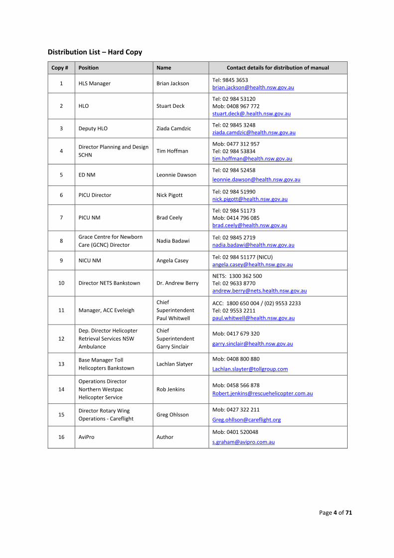
Distribution List – Hard Copy
Copy # Position Name Contact details for distribution of manual
1 HLS Manager Brian Jackson Tel: 9845 3653 [email protected]
2 HLO Stuart Deck Tel: 02 984 53120 Mob: 0408 967 772 [email protected]
3 Deputy HLO Ziada Camdzic Tel: 02 9845 3248 [email protected]
4 Director Planning and Design
SCHN Tim Hoffman
Mob: 0477 312 957 Tel: 02 984 53834 [email protected]
5 ED NM Leonnie Dawson Tel: 02 984 52458
6 PICU Director Nick Pigott Tel: 02 984 51990 [email protected]
7 PICU NM Brad Ceely Tel: 02 984 51173 Mob: 0414 796 085 [email protected]
8 Grace Centre for Newborn
Care (GCNC) Director Nadia Badawi
Tel: 02 9845 2719 [email protected]
9 NICU NM Angela Casey Tel: 02 984 51177 (NICU) [email protected]
10 Director NETS Bankstown Dr. Andrew Berry NETS: 1300 362 500 Tel: 02 9633 8770 [email protected]
11 Manager, ACC Eveleigh
Chief
Superintendent
Paul Whitwell
ACC: 1800 650 004 / (02) 9553 2233 Tel: 02 9553 2211 [email protected]
12
Dep. Director Helicopter
Retrieval Services NSW
Ambulance
Chief
Superintendent
Garry Sinclair
Mob: 0417 679 320
13 Base Manager Toll
Helicopters Bankstown Lachlan Slatyer
Mob: 0408 800 880
14
Operations Director
Northern Westpac
Helicopter Service
Rob Jenkins Mob: 0458 566 878
15 Director Rotary Wing
Operations - Careflight Greg Ohlsson
Mob: 0427 322 211
16 AviPro Author Mob: 0401 520048
Page 5 of 71
Table of Contents Explanation of Terms ................................................................................................................................. 8
Acronyms ................................................................................................................................................. 11
Figures ...................................................................................................................................................... 13
Tables ....................................................................................................................................................... 13
Part A – General Information ................................................................................................................... 14
1. Background .................................................................................................................................. 14
2. Key Contacts ................................................................................................................................. 15
3. Authority to Access HLS ............................................................................................................... 15
Part B – Helicopter Landing Site Design and Helicopter in Use ............................................................... 17
4. Advisory Information ................................................................................................................... 17
5. Helicopter Design Criteria ............................................................................................................ 17
6. Helicopter Performance Requirements ....................................................................................... 18
7. Other Helicopters ......................................................................................................................... 19
Part C – HLS Location and Coordinates .................................................................................................... 20
8. HLS Location ................................................................................................................................. 20
9. Landing Site Coordinates ............................................................................................................. 21
Part D – Helicopter Landing Site Design .................................................................................................. 22
10. HLS Specifications .................................................................................................................... 22
11. Orientation and Markings ........................................................................................................ 22
12. Dimensions ............................................................................................................................... 22
13. Lighting ..................................................................................................................................... 23
14. Lobby Communications Equipment ......................................................................................... 25
15. HLS Access and Egress .............................................................................................................. 25
16. HLS Safety and Specialist Equipment ....................................................................................... 25
17. Fire Fighting.............................................................................................................................. 26
18. Fire Detection and Alert Systems ............................................................................................. 26
19. Car Park Level 6 Exclusion System ........................................................................................... 28
20. HLS Tie Down Points ................................................................................................................ 28
Part E – Aircraft Operating Procedures .................................................................................................... 29
21. Flightpaths and Obstacle Survey .............................................................................................. 29
22. PC1 Survey (To be conducted) ................................................................................................. 30
23. Airspace Restrictions ................................................................................................................ 30
24. Communications ...................................................................................................................... 30
25. Communications - Inbound Patient ......................................................................................... 31
26. Departure ................................................................................................................................. 32
Page 6 of 71
27. Outbound Patient .................................................................................................................... 32
Part F – Patient Procedures ..................................................................................................................... 33
28. Notification .............................................................................................................................. 33
29. Switchboard ............................................................................................................................. 33
30. Inbound or Outbound Patient Ward Activity ........................................................................... 34
31. Porter/Duty HLO/Porter .......................................................................................................... 34
32. NETS or Helicopter Clinical Crew ............................................................................................. 34
33. HLO ........................................................................................................................................... 34
Part G – HLS Duties and Procedures ........................................................................................................ 35
34. HLS Manager ............................................................................................................................ 35
35. HLO ........................................................................................................................................... 35
36. Deputy HLO .............................................................................................................................. 35
37. Duty HLO/Porter ...................................................................................................................... 36
38. Switchboard (when Switchboard is notified of helicopter arrival) .......................................... 36
39. ICU/ED (when directly notified of helicopter arrival) .............................................................. 36
40. Car Park Control ....................................................................................................................... 36
Part H – Emergency Procedures .............................................................................................................. 37
41. General ..................................................................................................................................... 37
42. Helicopter Crash – No Fire ....................................................................................................... 37
43. Helicopter Crash - Fire ............................................................................................................. 37
44. Aircraft Not Fit for Flight (unserviceable) ................................................................................ 38
Part I – Training ........................................................................................................................................ 39
45. General ..................................................................................................................................... 39
46. HLO and Deputy HLO ............................................................................................................... 39
47. Duty HLO/Porter ...................................................................................................................... 39
48. Maintenance Personnel ........................................................................................................... 39
49. WHS and Executives ................................................................................................................. 40
Part J – HLS Maintenance ........................................................................................................................ 41
50. General ..................................................................................................................................... 41
51. Scheduled Maintenance and Inspection .................................................................................. 41
52. Maintenance Annual, Biannual and Quarterly Inspections ..................................................... 41
53. Monthly, Weekly and Daily Inspections ................................................................................... 41
54. Vacating the HLS for Helicopter Operations ............................................................................ 42
55. Out of Service Marker .............................................................................................................. 42
Part K – HLS Reporting Officer ................................................................................................................. 43
56. CASR Part 175 Aeronautical Information Management .......................................................... 43
Page 7 of 71
57. Data Specification Requirements ............................................................................................. 43
58. Data Requirements .................................................................................................................. 44
59. Electronic Format ..................................................................................................................... 44
60. Data Alterations and Error Tracking......................................................................................... 44
61. Data Verification ...................................................................................................................... 44
62. Data Integrity ........................................................................................................................... 44
Appendix 1 – Responsibilities and Duties ................................................................................................ 45
Appendix 2 - PC1 Survey Report .............................................................................................................. 48
Appendix 3 – HLO Monthly, Weekly and Daily Inspection Checklists ..................................................... 49
Appendix 4 - Training ............................................................................................................................... 55
Appendix 5 – Maintenance Plan .............................................................................................................. 58
Appendix 6 – Duty HLO/Porter Checklists ............................................................................................... 59
Appendix 7 – Aeronautical Data Forms ................................................................................................... 63
Appendix 8 – HLS Safety .......................................................................................................................... 64
Appendix 9 – HLS Certification ................................................................................................................. 66
Appendix 9A – HLS Load Bearing Certification ........................................................................................ 67
Appendix 9B – HLS NVG Compliance Certification .................................................................................. 68
Appendix 9C – HLS Electrical Certification ............................................................................................... 69
Appendix 9D – HLS Paint/Marking Certification ...................................................................................... 70
Appendix 9E – HLS Fire-fighting DIFFS Certification ................................................................................ 71
Page 8 of 71
Explanation of Terms Aircraft: Refers to both aeroplanes (fixed wing) and helicopters
(rotorcraft).
Approach/Departure Path (VFR): The flight track helicopters follow when landing at or departing
from the FATO of a HLS. The VFR approach and departure path
extends outwards from the edge of the FATO with an obstacle
free gradient of 2.5º or 4.5% or 1:22 vertical to horizontal,
measured from the edge of the FATO, to a height initially of 500
feet above the FATO at a distance of ~3,500m The path may be
curved left or right to avoid obstacles or to take advantage of a
better approach or departure path. Changes in direction by day
below 300 feet should be avoided and there should be no
changes in direction below 500 feet at night.
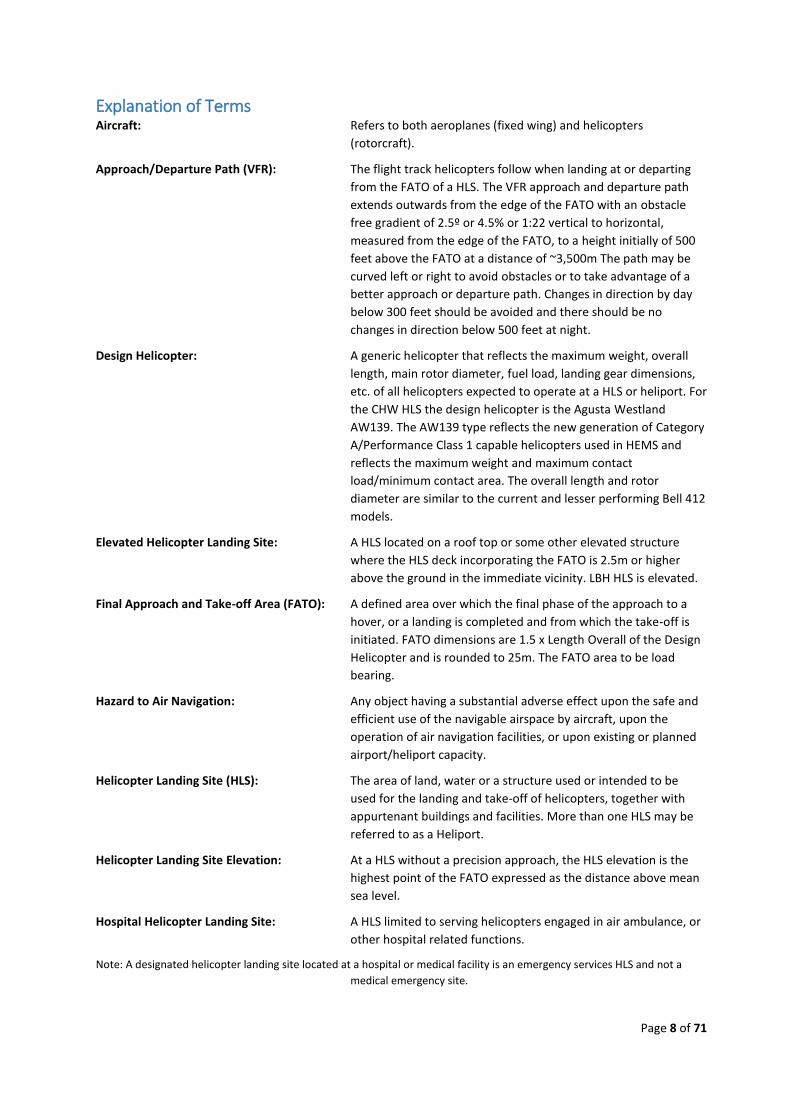
Design Helicopter: A generic helicopter that reflects the maximum weight, overall
length, main rotor diameter, fuel load, landing gear dimensions,
etc. of all helicopters expected to operate at a HLS or heliport. For
the CHW HLS the design helicopter is the Agusta Westland
AW139. The AW139 type reflects the new generation of Category
A/Performance Class 1 capable helicopters used in HEMS and
reflects the maximum weight and maximum contact
load/minimum contact area. The overall length and rotor
diameter are similar to the current and lesser performing Bell 412
models.
Elevated Helicopter Landing Site: A HLS located on a roof top or some other elevated structure
where the HLS deck incorporating the FATO is 2.5m or higher
above the ground in the immediate vicinity. LBH HLS is elevated.
Final Approach and Take-off Area (FATO): A defined area over which the final phase of the approach to a
hover, or a landing is completed and from which the take-off is
initiated. FATO dimensions are 1.5 x Length Overall of the Design
Helicopter and is rounded to 25m. The FATO area to be load
bearing.
Hazard to Air Navigation: Any object having a substantial adverse effect upon the safe and
efficient use of the navigable airspace by aircraft, upon the
operation of air navigation facilities, or upon existing or planned
airport/heliport capacity.
Helicopter Landing Site (HLS): The area of land, water or a structure used or intended to be
used for the landing and take-off of helicopters, together with
appurtenant buildings and facilities. More than one HLS may be
referred to as a Heliport.
Helicopter Landing Site Elevation: At a HLS without a precision approach, the HLS elevation is the
highest point of the FATO expressed as the distance above mean
sea level.
Hospital Helicopter Landing Site: A HLS limited to serving helicopters engaged in air ambulance, or
other hospital related functions.
Note: A designated helicopter landing site located at a hospital or medical facility is an emergency services HLS and not a
medical emergency site.
Page 9 of 71
HLS Reference Point (HRP): The geographic position of the HLS expressed as the latitude and
longitude at the centre of the FATO.
Length (Overall) (L): The distance from the tip of the main rotor tip plane path to the
tip of the tail rotor tip plane path or the fin if further aft, of the
Design Helicopter.
Lift Off: To raise the helicopter into the air.
Movement: A landing or a lift off of a helicopter.
Non Directional Beacon (NDB): A radio transmitter at a known location providing a radio signal to
an aircraft automatic direction finder (ADF).
Obstruction to Air Navigation: Any fixed or mobile object, including a parked helicopter, which
impinges the approach/departure surface or the transitional
surfaces.
Performance Class 1 (PC1): Similar to Category A requirements. For a rotorcraft, means the
class of rotorcraft operations where, in the event of failure of the
critical power unit, performance is available to enable the
rotorcraft to land within the rejected take-off distance available,
or safely continue the flight to an appropriate landing area,
depending on when the failure occurs. PC1 from a HLS requires
CASA approved VFR approach and departure paths with obstacles
marked and crew briefed. The Ambulance NSW AW139 is capable
of PC1.
Performance Class 2 (PC2): For a rotorcraft, means the class of rotorcraft operations where,
in the event of failure of the critical power unit, performance is
available to enable the rotorcraft to safety continue the flight,
except when the failure occurs early during the take-off
manoeuvre, in which case a forced landing may be required. PC2
from a HLS requires CASA approved VFR approach and departure
paths with obstacles marked and crew briefed.
Performance Class 3 (PC3): For a rotorcraft, means the class of rotorcraft operations where,
in the event of failure of the critical power unit at any time during
the flight, a forced landing:
a. in the case of multi-engine rotorcraft – may be
required; or
b. in the case of single-engine rotorcraft – will be
required.
Pilot Activated Lighting (PAL): A PAL system utilises a hospital based VHF radio and timed
switching device, activated by the pilot via a VHF radio
transmission on a pre-set frequency, to turn on the HLS lighting.
Prior Permission Required (PPR) HLS: A HLS developed for exclusive use of the owner and persons
authorized by the owner, i.e. CHW HLS.
Note: The HLS owner and operator are to ensure that all pilots are
thoroughly knowledgeable with the HLS (including such features as
approach/departure path characteristics, preferred heading, facility
limitations, lighting, obstacles in the area, size of the facility, PC1 survey
etc.).
Page 10 of 71
Rotor Downwash: The volume of air moved downward by the action of the rotating
main rotor blades. When this air strikes the ground or some other
surface, it causes a turbulent outflow of air from beneath the
helicopter.
Safety Area: A defined area on a HLS surrounding the FATO intended to
reduce the risk of damage to helicopters accidentally diverging
from the FATO (0.3 x RD of the Design Helicopter). This area
should be free of objects, other than those frangible mounted
objects required for air navigation purposes. For the Design
Helicopter, the Safety Area extends from the FATO by four
metres providing an overlaid diameter of 33m.
Safety Net: Surrounds the outer edge of a rooftop HLS. Should be a minimum
of 1.5m wide, not project more than 25cm. above the HLS outer
edge, have a load carrying capacity of not less than 122kg/m2,
and be fastened to a solid structure.
Shielded Obstruction: A proposed or existing obstruction that does not need to be
marked or lit due to its close proximity to another obstruction
whose highest point is at the same or higher elevation.
Suitable Forced Landing Area: For a flight of a rotorcraft: Means an area of land on which the
rotorcraft could make a forced landing with a reasonable
expectation that there would be no injuries to persons in the
rotorcraft or on the ground.
Take-off: To accelerate and commence climb at the relevant climb speed.
Take-off Position: A load bearing, generally paved area, normally located on the
centreline and at the edge of the TLOF, from which the helicopter
takes off. Typically, there are two such positions at the edge of
the TLOF, one for each of two take-off or arrival directions.
Touchdown and Lift-off Area (TLOF): A load bearing, generally paved area, normally centred in the
FATO, on which the helicopter lands or takes off, and that
provides ground effect for a helicopter rotor system. Size is based
on 1 x main rotor diameter of Design Helicopter. As the TLOF is
within the FATO, the area must be load bearing.
Transitional Surfaces: Starts from the edges of the FATO parallel to the flight path
centre line, and from the outer edges of approach/departure
surface, and extends outwards at a slope of 2:1 (2 units horizontal
in 1 unit vertical) for a distance of ~75m from the centreline. The
transitional surfaces start at the edge of the FATO opposite the
approach/departure surfaces and extend to the end of the
approach/departure surface at ~3,500m.
Unshielded Obstruction: A proposed or existing obstruction that may need to be marked
or lit since it is not in close proximity to another marked and lit
obstruction whose highest point is at the same or higher
elevation.
Page 11 of 71
Acronyms Acronym Meaning
AC Advisory Circular (USA FAA)
ACC Aeromedical Control Centre (Eveleigh NSW)
ADF Aeronautical Direction Finder
AEO All Engines Operating
ADON After Hours Duty Operating Nurse
AIP SUP Aeronautical Information Publication Supplement
AS Australian Standard
CAAP Civil Aviation Advisory Publication (Australia)
CAOs Civil Aviation Orders (Australia)
CARs Civil Aviation Regulation 1988 (Australia)
CASA Civil Aviation Safety Authority (Australia)
CASR Civil Aviation Safety Regulation 1998 (Australia)
CTAF Common Traffic Advisory Frequency
DH/DoH Department of Health NSW
DDO Design Development Overlay (for obstruction protection below VFR approach and departure paths)
ED Emergency Department
ETA Estimated Time of Arrival
ETD Estimated Time of Departure
FAA Federal Aviation Administration (USA)
FATO Final Approach and Take-off Area
FATO/TLOF Coincident FATO and TLOF areas
FIS Flight Information Service
GPS Global Positioning System
HAPI-PLASI Helicopter Approach Path Indicator - Pulse Light Approach Slope Indicator (see VGI)
HEMS Helicopter Emergency Medical Service
HLO Helicopter Landing Site Officer
HLS Helicopter Landing Site
ICAO International Civil Aviation Association
IIMS Incident Investigation Management System
IMC Instrument Meteorological Conditions
IWDI Illuminated Wind Direction Indicator (aka Windsock)
L Length (overall), in relation to a helicopter
MCP Manual Call Point
MOS Manual of Standards (CASA)
MRI Magnetic Resonance Imagers
MTOW Maximum Take Off Weight
NDB Non Directional Beacon
NETS Newborn and Paediatric Emergency Transport Service
NICU Neonatal Intensive Care Unit (aka Grace Ward)
Page 12 of 71
Acronym Meaning
NM Nurse Manager
NUM Nurse Unit Manager
OAA Obstacle Accountability Area
OEI One Engine Inoperative
PAL Pilot Activated Lighting
PC1 Performance Class 1
PC2 Performance Class 2
PC3 Performance Class 3
PFC Patient Flow Coordinator
PIC Pilot in Command
PICU Paediatric Intensive Care Unit
POB Persons-on-board
PPE Personal Protection Equipment
PPR Prior Permission Required
RD Rotor Diameter (Main)
RMI Remote Magnetic Indicator (Magnetic compass with flux valve system)
SARPS Standards and Recommended Practices (Developed by ICAO and promulgated in the Annexes to the
Convention of International Civil Aviation)
SFLA Suitable Forced Landing Area
TDPM Touchdown Positioning Marking (“H”)
TLOF Touchdown and Lift Off Area
UHF Ultra-High Frequency
VFR Visual Flight Rules
VGI Visual Guidance Indicator (helicopter visual approach guidance to a HLS)
VHF Very High Frequency
VMC Visual Meteorological Conditions - Allows flight under VFR
VOR VHF Omni-directional Radio (A ground radio VHF transmission for aircraft navigation
purposes)
WGS84 World Geodetic Survey 1984
Page 13 of 71
Figures
1: Ambulance NSW AW139.
2: AW139 Design helicopter dimensions.
3: Care Flight BK117.
4: Westpac Rescue B412.
5: Westpac Rescue AS356N.
6: Army Black Hawk.
7: Western Sydney (map).
8: CHW and Parramatta (map).
9: Hospital and HLS and flight paths.
10: Plan imagery of HLS Marking
11. HLS “H” Orientation to Magnetic North
12: CHW HLS Deck Markings.
13: Lift well at CHW
14: Emergency Exit
15: Fire extinguisher – 90 lr
16: Hose reel system
17: DIFFS components
18: DIFFS Activated
19: Car Park Level 5 Exclusion System
20: Helicopter Tie Down Points
21: VFR Approach and Departure Paths (Plan View)
Tables
1: Key Contacts
2: HLS Call List
3: HLO Training
Page 14 of 71
Part A – General Information 1. Background
1.1. Ambulance NSW provide a fleet of helicopters for the provision of aeromedical retrieval
services, search, rescue and primary emergency recovery across NSW. Major hospitals
and many regional hospitals are equipped with a helicopter emergency medical service
(HEMS) Helicopter Landing Site (HLS) located either on a hospital building rooftop or at
ground level within the campus. At some more remote hospitals, the HLS may be outside
the campus boundary. CHW has an elevated HLS.
1.2. Ambulance NSW HEMS is vested with the operational responsibility for hospital based
HLS in NSW. To ensure that operations at hospital HLS are undertaken safely and
efficiently, it is necessary that appropriate procedures are in place.
1.3. The Neonatal Emergency Transport Service (NETS) has been established to support child
and newborn patient transfers. NETS provides specialist medical crews and equipment for
child patient transfers.
1.4. This HLS Operations Manual covers the following areas:
a. Part 1: General Information
b. Part 2: HLS Design Criteria & Helicopters in Use
c. Part 3: HLS Location
d. Part 4: HLS Design
e. Part 5: Aircraft Operating Procedures
f. Part 6: Patient Transfer Procedures
g. Part 7: HLS Management
h. Part 8: Emergency Procedures
i. Part 9: Training
j. Part 10: HLS Maintenance
k. Appendices: 1 through 9
1.5. The use of Ambulance NSW HEMS and NETS for child patient transport to and from CHW
ensures that optimum health care can be provided for time critical patients. A dedicated
Helicopter Landing Site Officer (HLO) is appointed to manage the HLS and to ensure
efficient patient handling and HEMS movements 24 hours per day. The HLO will liaise
with and provide assistance to Ambulance NSW crew and NETS crew as required. Patients
remain under the control of NETS crew or Ambulance NSW clinical crew from or until ICU
or ED bedside handover.
1.6. The HLS is primarily for the purpose of accommodating HEMS transfer of patients and
equipment to and from CHW. It will not be used for commercial or private flights. HEMS is
deemed to hold the prior permission required from CHW for operations to the HLS.
1.7. There may be occasions when Ambulance NSW request access to the HLS for other than
routine patient transfer, such as non-patient flights involving the collection of clinical staff
and equipment, or for flight crew training purposes. In such cases Ambulance NSW will
provide CHW with appropriate advance notification of the requirement. In consultation
with Ambulance NSW, the HLO will provide assistance where possible.
Page 15 of 71
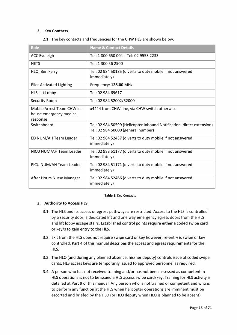
2. Key Contacts
2.1. The key contacts and frequencies for the CHW HLS are shown below:
Role Name & Contact Details
ACC Eveleigh Tel: 1 800 650 004 Tel: 02 9553 2233
NETS Tel: 1 300 36 2500
HLO, Ben Ferry Tel: 02 984 50185 (diverts to duty mobile if not answered immediately)
Pilot Activated Lighting Frequency: 128.00 MHz
HLS Lift Lobby Tel: 02 984 69617
Security Room Tel: 02 984 52002/52000
Mobile Arrest Team CHW in-house emergency medical response
x4444 from CHW line, via CHW switch otherwise
Switchboard Tel: 02 984 50599 (Helicopter Inbound Notification, direct extension) Tel: 02 984 50000 (general number)
ED NUM/AH Team Leader Tel: 02 984 52437 (diverts to duty mobile if not answered immediately)
NICU NUM/AH Team Leader Tel: 02 983 51177 (diverts to duty mobile if not answered immediately)
PICU NUM/AH Team Leader Tel: 02 984 51171 (diverts to duty mobile if not answered immediately)
After Hours Nurse Manager Tel: 02 984 52466 (diverts to duty mobile if not answered immediately)
Table 1: Key Contacts
3. Authority to Access HLS
3.1. The HLS and its access or egress pathways are restricted. Access to the HLS is controlled
by a security door, a dedicated lift and one way emergency egress doors from the HLS
and lift lobby escape stairs. Established control points require either a coded swipe card
or key/s to gain entry to the HLS.
3.2. Exit from the HLS does not require swipe card or key however, re-entry is swipe or key
controlled. Part 4 of this manual describes the access and egress requirements for the
HLS.
3.3. The HLO (and during any planned absence, his/her deputy) controls issue of coded swipe
cards. HLS access keys are temporarily issued to approved personnel as required.
3.4. A person who has not received training and/or has not been assessed as competent in
HLS operations is not to be issued a HLS access swipe card/key. Training for HLS activity is
detailed at Part 9 of this manual. Any person who is not trained or competent and who is
to perform any function at the HLS when helicopter operations are imminent must be
escorted and briefed by the HLO (or HLO deputy when HLO is planned to be absent).
Page 16 of 71
3.5. Training and competency requirements for persons who require access to the HLS at
times when helicopter operations are not imminent are also detailed at Part 9.
3.6. For helicopter operations (helicopter on the helipad or inbound within 10 minutes of the
HLS) the HLO, deputy HLO, AH HLO and Duty HLO/Porter would normally be the approved
persons. Aircrew and clinical crew associated with the helicopter are always escorted to
the HLS and may exit the HLS at any time.
3.7. For other than those times described above the CHW HLS Manager, CHW Maintenance
Manager or WHS Manager may need access to the HLS. The HLO remains the authority
for such access and will provide suitable controls for such access. Any PR, maintenance or
inspection activity at the HLS must be supervised by a person who is trained and
competent for HLS activity.
3.8. Additional maintenance personnel controls are described at Part 9 of this manual.
Page 17 of 71
Part B – Helicopter Landing Site Design and Helicopter in Use
4. Advisory Information
4.1. The CHW HLS has been designed to meet the requirements of the MoH Guidelines for
Hospital Helicopter Landing Sites in NSW, 2017. The Guidelines are based upon a
number of international documents applicable to helicopter operations and current basic
CASA advisory material. They include:
a. ICAO Annex 6: Operation of Aircraft - Part III: International Operations - Helicopters 6th
Edition July 2004.
b. ICAO Annex 14, Aerodromes - Volume II: Heliports 4th Edition 2013.
c. ICAO Heliport Manual Doc 9261-AN/903 3rd. Edition in 1995.
d. US FAA Advisory Circular AC 150/5390-2C, Heliport Design, (covers both operational and
design criteria, particularly for hospital based HLSs in Chapter 4, Hospital Heliports) April
2012.
e. CASA (CAAP) 92-2 (2) Guidelines for the Establishment and Operation of Onshore
Helicopter Landing Sites.
4.2. The appropriate legislation at present for the use of HLS is Civil Aviation Regulation
(CAR) 92 which places the onus on the helicopter pilot to determine the suitability of a
landing site.
5. Helicopter Design Criteria
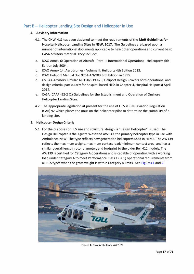
5.1. For the purposes of HLS size and structural design, a “Design Helicopter” is used. The
Design Helicopter is the Agusta Westland AW139, the primary helicopter type in use with
Ambulance NSW. The type reflects new generation helicopters used in HEMS. The AW139
reflects the maximum weight, maximum contact load/minimum contact area, and has a
similar overall length, rotor diameter, and footprint to the older Bell 412 models. The
AW139 is certified for Category A operations and is capable of operating with a working
load under Category A to meet Performance Class 1 (PC1) operational requirements from
all HLS types when the gross weight is within Category A limits. See Figures 1 and 2.
Figure 1: NSW Ambulance AW 139
Page 18 of 71
6. Helicopter Performance Requirements
6.1. ICAO Annex 6 Part III defines three performance categories for helicopters and the
proposed CASA CASRs Part 133 and Part 138 are proposed to adopt the ICAO
Performance Classes.
6.2. HEMS operations on behalf of Ambulance NSW in the AW139 are conducted whenever
possible, to meet Category A capability (single engine accountability). At HLS where
appropriate VFR approach and departure path surveys have been completed and are
current, helicopters will operate to Performance Class 1 (PC1). Refer to the Explanation of
Terms for the definitions of PC1, PC2 and PC3.
6.3. By definition, single-engine helicopters can only operate to PC3. Similarly, the PC1 criteria
can only be met by multi-engine helicopters. Most multi-engine helicopters are in
Transport Category however due to a lower level of complexity, some twin-engine
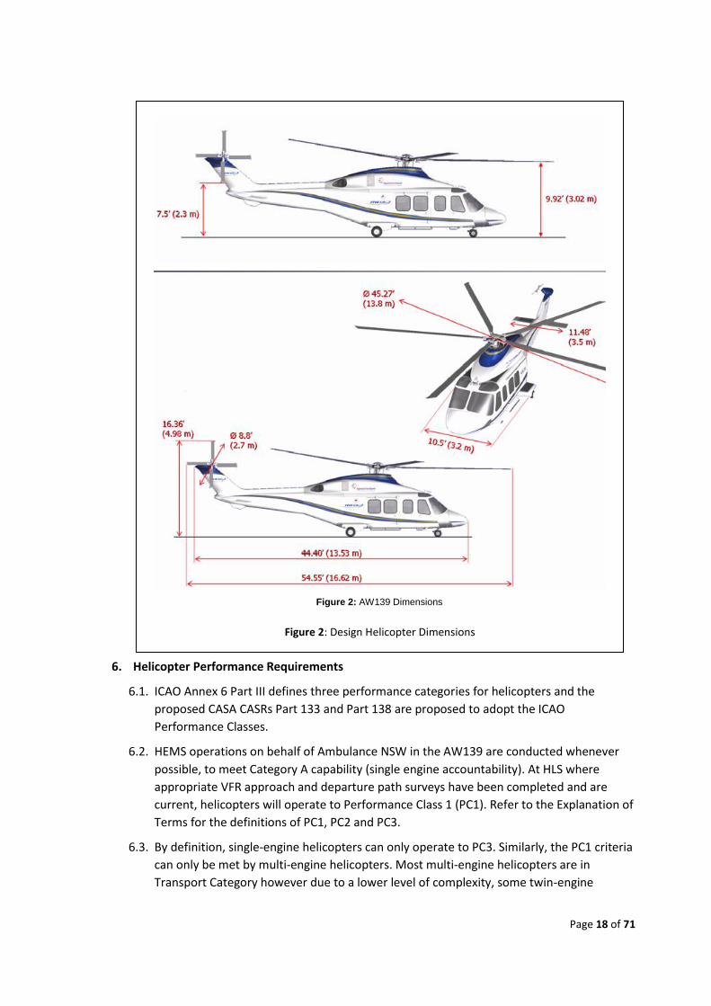
Figure 2: Design Helicopter Dimensions
Figure 2: AW139 Dimensions
Page 19 of 71
helicopters are in Normal Category. Generally speaking, Normal Category helicopters
have limited PC1 capability and would therefore operate primarily under PC2.
6.4. CHW HLS has been designed to meet the ICAO take-off climb gradient recommendations
of 2.5° (4.5% or 1:22) along two VFR approach and departure paths 180 degrees apart.
ICAO Annex 14 Volume II notes that this minimum Take-Off Climb Surface gradient for
PC1 operations is steeper than the minimum achievable OEI gradient for many older
generation helicopters. The AW139 operating at PC1 achieves the required performance.
7. Other Helicopters
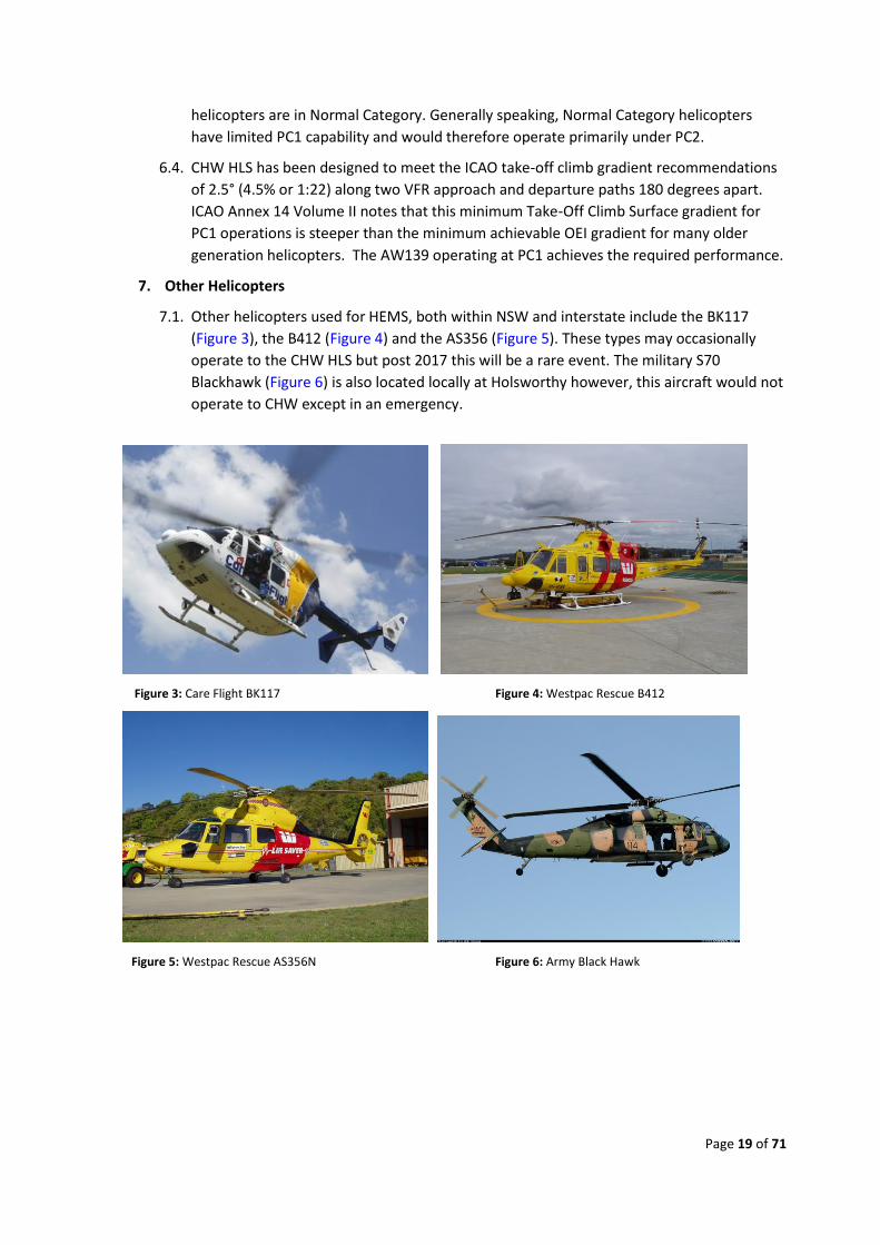
7.1. Other helicopters used for HEMS, both within NSW and interstate include the BK117
(Figure 3), the B412 (Figure 4) and the AS356 (Figure 5). These types may occasionally
operate to the CHW HLS but post 2017 this will be a rare event. The military S70
Blackhawk (Figure 6) is also located locally at Holsworthy however, this aircraft would not
operate to CHW except in an emergency.
Figure 3: Care Flight BK117 Figure 4: Westpac Rescue B412
Figure 5: Westpac Rescue AS356N Figure 6: Army Black Hawk
Page 20 of 71
Part C – HLS Location and Coordinates
8. HLS Location
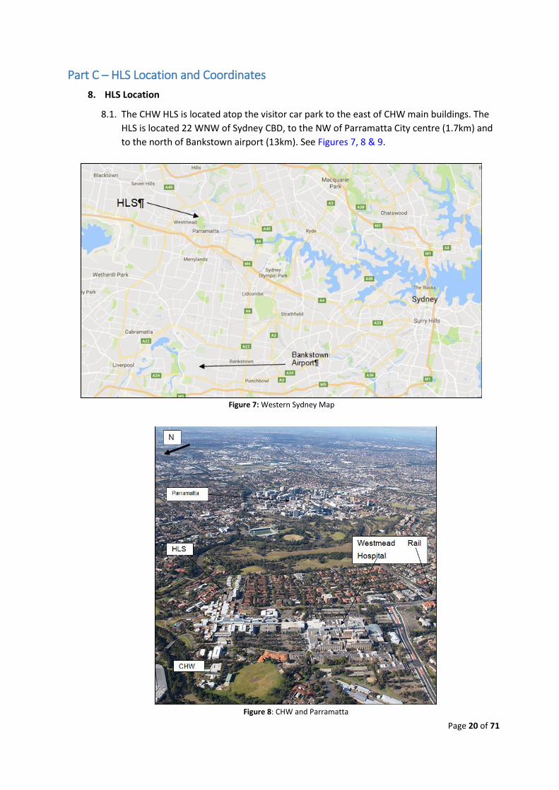
8.1. The CHW HLS is located atop the visitor car park to the east of CHW main buildings. The
HLS is located 22 WNW of Sydney CBD, to the NW of Parramatta City centre (1.7km) and
to the north of Bankstown airport (13km). See Figures 7, 8 & 9.
Figure 7: Western Sydney Map
Figure 8: CHW and Parramatta
Page 21 of 71
9. Landing Site Coordinates
9.1. The geospatial coordinates for CHW HLS are:
a. S 33° 48’ 08.49”
b. E 150° 59’ 37 10”
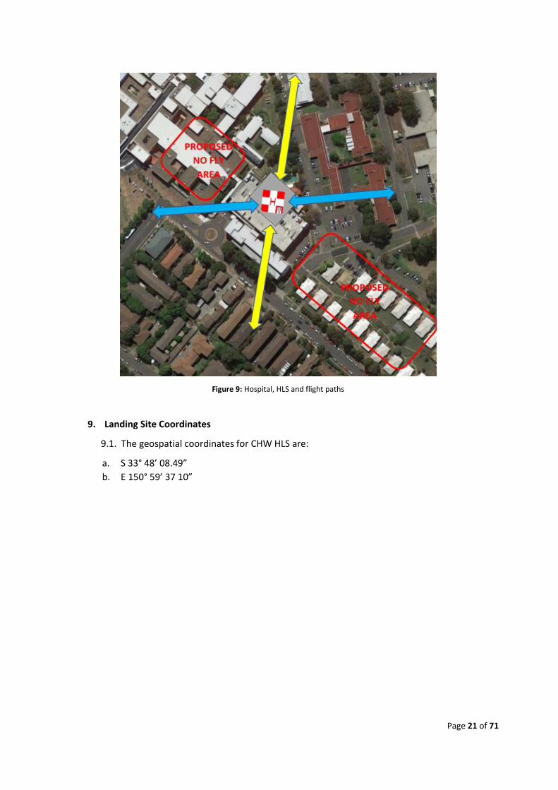
Figure 9: Hospital, HLS and flight paths
Page 22 of 71
Part D – Helicopter Landing Site Design
10. HLS Specifications
10.1. The Hospital’s HLS is a pre-fabricated Aluminium Offshore supplied elevated landing site
and has been designed to meet the Design Helicopter maximum static load of 6.8 tons.
This limitation is marked on the deck in the static load and TLOF box. The HLS is a single
helicopter design – there is no parking area.
10.2. The Certification of the HLS are at Appendix 9.
11. Orientation and Markings
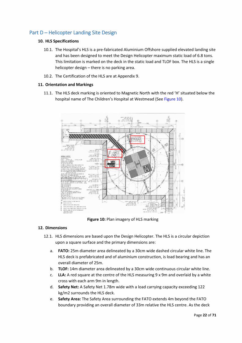
11.1. The HLS deck marking is oriented to Magnetic North with the red ‘H’ situated below the
hospital name of The Children’s Hospital at Westmead (See Figure 10).
Figure 10: Plan imagery of HLS marking
12. Dimensions
12.1. HLS dimensions are based upon the Design Helicopter. The HLS is a circular depiction
upon a square surface and the primary dimensions are:
a. FATO: 25m diameter area delineated by a 30cm wide dashed circular white line. The
HLS deck is prefabricated and of aluminium construction, is load bearing and has an
overall diameter of 25m.
b. TLOF: 14m diameter area delineated by a 30cm wide continuous circular white line.
c. LLA: A red square at the centre of the HLS measuring 9 x 9m and overlaid by a white
cross with each arm 9m in length.
d. Safety Net: A Safety Net 1.78m wide with a load carrying capacity exceeding 122
kg/m2 surrounds the HLS deck.
e. Safety Area: The Safety Area surrounding the FATO extends 4m beyond the FATO
boundary providing an overall diameter of 33m relative the HLS centre. As the deck
Page 23 of 71
diameter is 25m and the Safety Net is 1.5m wide, the Safety Area beyond the Safety
Net is a further 2.5m.
f. Flight Paths: Two VFR approach/departure paths are marked on the HLS deck between
the TLOF and FATO boundary markings with yellow double headed arrows. Paths in
the northern sector are 180°/360°, and in the southern sector, 360°/180°, relative to
True North.
g. Windsock: Westmead HLS has a yellow, 2.4m windsock mounted on a pole over the
lift lobby/HLS reception room.
13. Lighting
13.1. HLS lighting consists of the following:
a. FATO: The perimeter of the FATO is defined by 12 uniformly spaced flush mounted
green NVG compliant lights.
b. TLOF: The perimeter of the TLOF is defined by 8 uniformly spaced flush mounted
green NVG compliant lights.
c. Flight Paths: The two VFR approach and departure path arrows each have three flush
mounted yellow NVG compliant lights.
d. Flood lights: Two flood lights are mounted on the east facing wall of the lift lobby to
illuminate the HLS deck during patient loading and unloading.
e. Windsock: The windsock is illuminated from above by four white lights. A red steady
obstruction light is positioned at the top of the windsock pole.
f. Hospital HLS Beacon: A low intensity Hospital HLS Identification Beacon with a flashing
Identification white/green/yellow at the rate of 30 to 45 flashes per minute and visible
at a range of 10-12 nm is located on the top of the lift lobby.
g. Obstruction Lights: Additional low intensity steady red obstruction lights are
positioned at various points on high obstructions within the hospital campus.
h. Emergency Exit Lighting: Emergency exit lighting is located at both the lift lobby
entrance and its associated emergency stairwell and at the emergency stairs on the SE
side of the HLS deck.
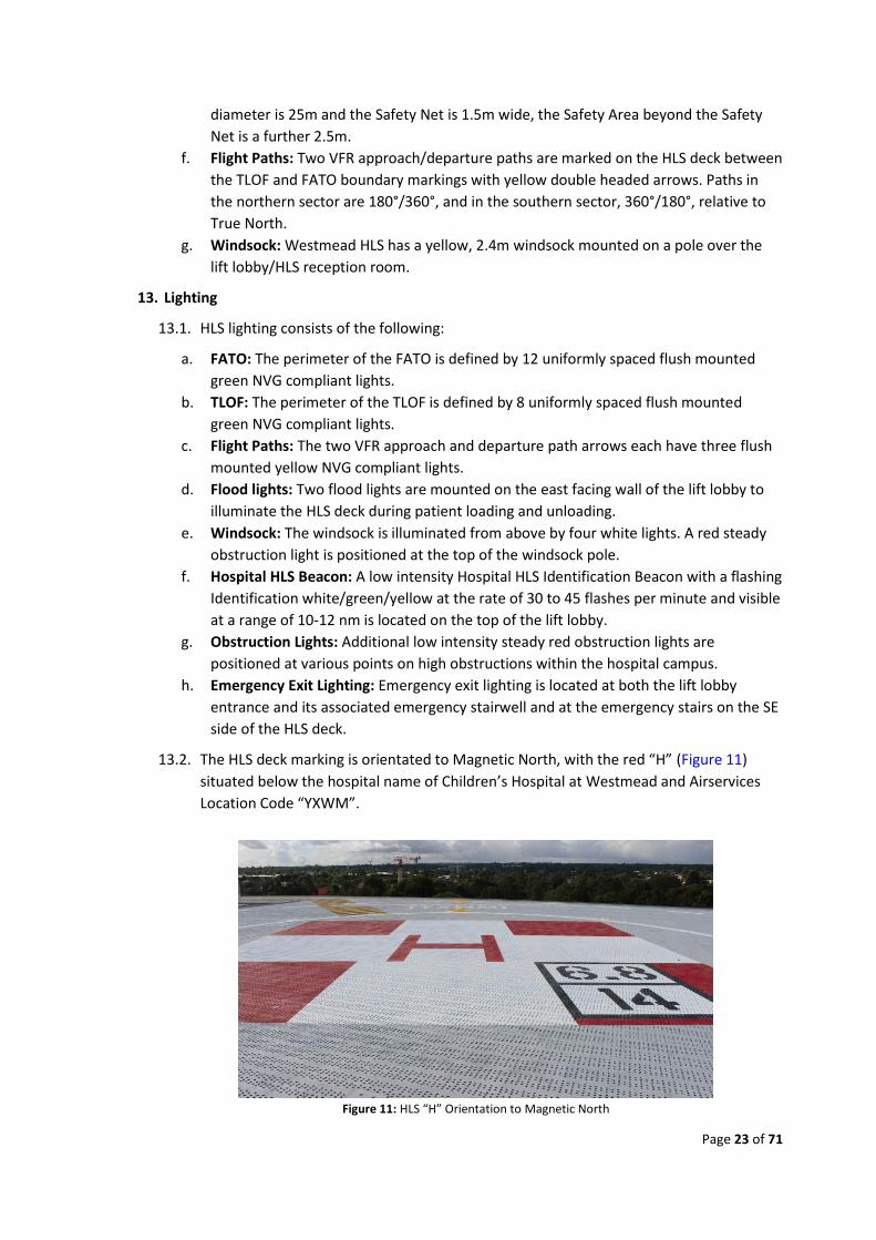
13.2. The HLS deck marking is orientated to Magnetic North, with the red “H” (Figure 11)
situated below the hospital name of Children’s Hospital at Westmead and Airservices
Location Code “YXWM”.
Figure 11: HLS “H” Orientation to Magnetic North
Page 24 of 71
Markings
13.3. The HLS deck is sealed with a non-slip, hydrocarbon and U/V resistant neutral grey
paint. HLS deck has a FATO of 25m diameter defined by a broken white circle. Within
the FATO is a TLOF of 14m diameter defined by a full white circle. Both the FATO and
TLOF have coincident flush mounted green perimeter lights.
13.4. At the centre of the TLOF is a red square with a white cross and red “H”. At the lower
right of the red square is a limit box denoting the maximum static weight limit in tons
and the TLOF diameter in metres (main rotor diameter).
13.5. The “H” and limit box are orientated to Magnetic North and the hospital name and
Airservices identifier are positioned above the red square between the TLOF and FATO
markings. Distance to the MRI in metres is marked on the deck.
13.6. The path from the lift lobby is denoted by black and yellow chevrons. The emergency
exit is located at the SE side of the HLS deck and is marked in yellow with warning
advice.
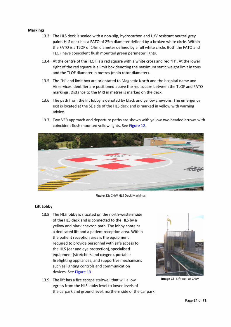
13.7. Two VFR approach and departure paths are shown with yellow two headed arrows with
coincident flush mounted yellow lights. See Figure 12.
Lift Lobby
13.8. The HLS lobby is situated on the north-western side
of the HLS deck and is connected to the HLS by a
yellow and black chevron path. The lobby contains
a dedicated lift and a patient reception area. Within
the patient reception area is the equipment
required to provide personnel with safe access to
the HLS (ear and eye protection), specialised
equipment (stretchers and oxygen), portable
firefighting appliances, and supportive mechanisms
such as lighting controls and communication
devices. See Figure 13.
13.9. The lift has a fire escape stairwell that will allow
egress from the HLS lobby level to lower levels of
the carpark and ground level, northern side of the car park.
Image 13: Lift well at CHW
Figure 12: CHW HLS Deck Markings
Page 25 of 71
14. Lobby Communications Equipment
14.1. The HLS communications equipment is located within the Lift Lobby and includes:
a. A Westmead Hospital telephone for normal telephone communications.
b. Westmead Hospital UHF base radio used to communicate with the HEMS aircraft.
15. HLS Access and Egress
15.1. The HLS deck has normal access via the lift lobby. The lift servicing the HLS is a dedicated
system accessible only via the HLS or CHW level 3 HLS corridor. Should the lift fail,
access to or from the HLS may be achieved via either emergency egress route, described
below.
15.2. Patient movement via these routes requires additional manpower however a vehicle
may be brought up to level 6 of the car park and the SE egress stairs used. Note that the
control gate for these stairs requires a key for entry to the HLS, but not for exit.
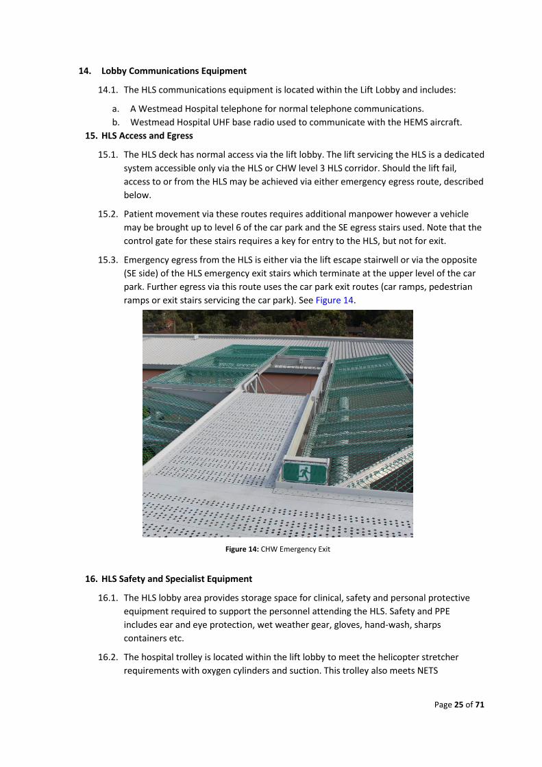
15.3. Emergency egress from the HLS is either via the lift escape stairwell or via the opposite
(SE side) of the HLS emergency exit stairs which terminate at the upper level of the car
park. Further egress via this route uses the car park exit routes (car ramps, pedestrian
ramps or exit stairs servicing the car park). See Figure 14.
16. HLS Safety and Specialist Equipment
16.1. The HLS lobby area provides storage space for clinical, safety and personal protective
equipment required to support the personnel attending the HLS. Safety and PPE
includes ear and eye protection, wet weather gear, gloves, hand-wash, sharps
containers etc.
16.2. The hospital trolley is located within the lift lobby to meet the helicopter stretcher
requirements with oxygen cylinders and suction. This trolley also meets NETS
Figure 14: CHW Emergency Exit
Page 26 of 71
equipment requirements. Standards for hospital helipad trolleys are listed in the NSW
Health 'NSW Critical Care Tertiary Referral Networks & Transfer of Care (Adults)'.
17. Fire Fighting
17.1. The main fire-fighting component for the CHW HLS is the deck integrated fire-fighting
system (DIFFS). The DIFFS Certificate is at Appendix 9E.
17.2. Fire-fighting equipment positioned inside the lift lobby includes:
a. 1 x 3.5 kg CO2 fire extinguisher,
b. 1 x 9.0 kg Dry Powder fire extinguisher,
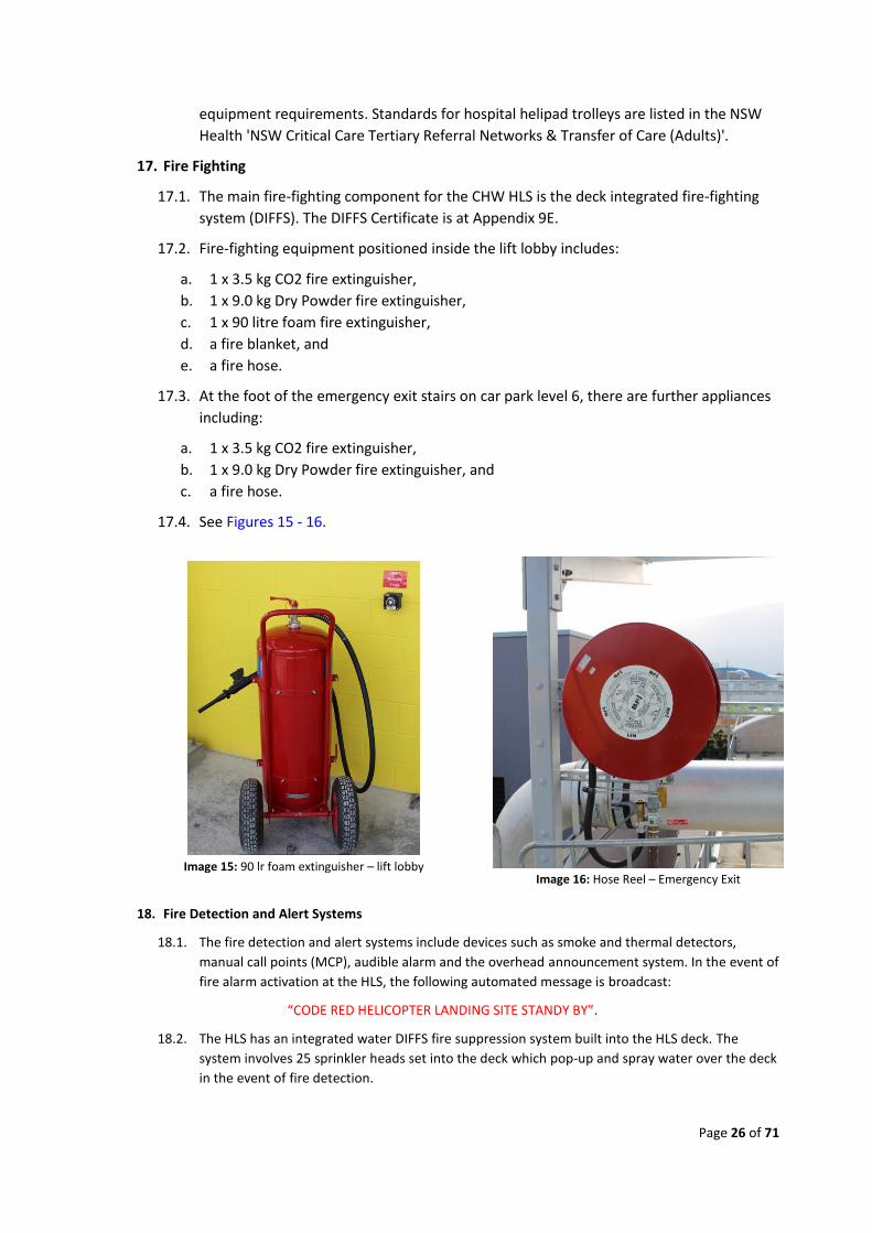
c. 1 x 90 litre foam fire extinguisher,
d. a fire blanket, and
e. a fire hose.
17.3. At the foot of the emergency exit stairs on car park level 6, there are further appliances
including:
a. 1 x 3.5 kg CO2 fire extinguisher,
b. 1 x 9.0 kg Dry Powder fire extinguisher, and
c. a fire hose.
17.4. See Figures 15 - 16.
18. Fire Detection and Alert Systems
18.1. The fire detection and alert systems include devices such as smoke and thermal detectors,
manual call points (MCP), audible alarm and the overhead announcement system. In the event of
fire alarm activation at the HLS, the following automated message is broadcast:
“CODE RED HELICOPTER LANDING SITE STANDY BY”.
18.2. The HLS has an integrated water DIFFS fire suppression system built into the HLS deck. The
system involves 25 sprinkler heads set into the deck which pop-up and spray water over the deck
in the event of fire detection.
Image 15: 90 lr foam extinguisher – lift lobby
Image 16: Hose Reel – Emergency Exit
Page 27 of 71
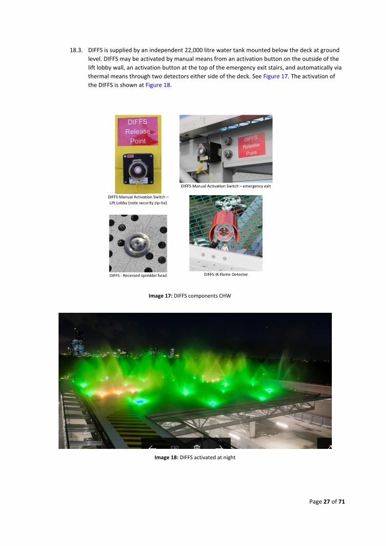
18.3. DIFFS is supplied by an independent 22,000 litre water tank mounted below the deck at ground
level. DIFFS may be activated by manual means from an activation button on the outside of the
lift lobby wall, an activation button at the top of the emergency exit stairs, and automatically via
thermal means through two detectors either side of the deck. See Figure 17. The activation of
the DIFFS is shown at Figure 18.
Image 17: DIFFS components CHW
Image 18: DIFFS activated at night
Page 28 of 71
19. Car Park Level 6 Exclusion System
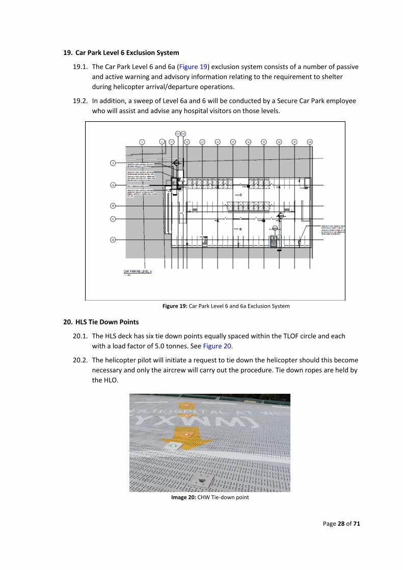
19.1. The Car Park Level 6 and 6a (Figure 19) exclusion system consists of a number of passive
and active warning and advisory information relating to the requirement to shelter
during helicopter arrival/departure operations.
19.2. In addition, a sweep of Level 6a and 6 will be conducted by a Secure Car Park employee
who will assist and advise any hospital visitors on those levels.
20. HLS Tie Down Points
20.1. The HLS deck has six tie down points equally spaced within the TLOF circle and each
with a load factor of 5.0 tonnes. See Figure 20.
20.2. The helicopter pilot will initiate a request to tie down the helicopter should this become
necessary and only the aircrew will carry out the procedure. Tie down ropes are held by
the HLO.
Figure 19: Car Park Level 6 and 6a Exclusion System
Image 20: CHW Tie-down point
Page 29 of 71
Part E – Aircraft Operating Procedures
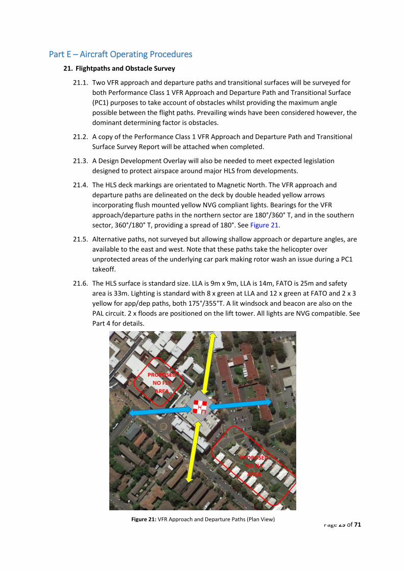
21. Flightpaths and Obstacle Survey
21.1. Two VFR approach and departure paths and transitional surfaces will be surveyed for
both Performance Class 1 VFR Approach and Departure Path and Transitional Surface
(PC1) purposes to take account of obstacles whilst providing the maximum angle
possible between the flight paths. Prevailing winds have been considered however, the
dominant determining factor is obstacles.
21.2. A copy of the Performance Class 1 VFR Approach and Departure Path and Transitional
Surface Survey Report will be attached when completed.
21.3. A Design Development Overlay will also be needed to meet expected legislation
designed to protect airspace around major HLS from developments.
21.4. The HLS deck markings are orientated to Magnetic North. The VFR approach and
departure paths are delineated on the deck by double headed yellow arrows
incorporating flush mounted yellow NVG compliant lights. Bearings for the VFR
approach/departure paths in the northern sector are 180°/360° T, and in the southern
sector, 360°/180° T, providing a spread of 180°. See Figure 21.
21.5. Alternative paths, not surveyed but allowing shallow approach or departure angles, are
available to the east and west. Note that these paths take the helicopter over
unprotected areas of the underlying car park making rotor wash an issue during a PC1
takeoff.
21.6. The HLS surface is standard size. LLA is 9m x 9m, LLA is 14m, FATO is 25m and safety
area is 33m. Lighting is standard with 8 x green at LLA and 12 x green at FATO and 2 x 3
yellow for app/dep paths, both 175°/355°T. A lit windsock and beacon are also on the
PAL circuit. 2 x floods are positioned on the lift tower. All lights are NVG compatible. See
Part 4 for details.
Figure 21: VFR Approach and Departure Paths (Plan View)
Page 30 of 71
22. PC1 Survey (To be conducted)
22.1. A Performance Class 1 survey of the primary VFR approach and departure paths and
transitional surfaces produced no obstacles penetrating 2.5º (4.5%) along either VFR
approach and departure path or the associated transitional surfaces. Flight paths were
surveyed out to 3.5 km. The survey report will be attached at Appendix 2.
23. Airspace Restrictions
23.1. CHW is located approximately 13 km. North of Sydney Metropolitan Airport
(Bankstown). The Bankstown northern VFR light aircraft lane tracks overhead
Parramatta at 1500ft. The airspace above CHW is uncontrolled and designated as a
Danger Area (D539B) due to its proximity to Bankstown and Sydney and is regularly
used for light aircraft flight training. Sydney Centre ATC frequency 124.55 is used
overhead CHW.
23.2. The Sydney International and Domestic Airport control zone is to the east and south of
CHW at lower level 2000ft, overlying the light aircraft lane. Richmond military controlled
airspace (R470 from surface to 4500ft) begins approximately 10km to the NW of CHW.
23.3. Current information is contained within the ERSA and Enroute Charts. Additional
pictorial information is available via the CASA ‘On Track’ web site at
http://ontrack.casa.gov.au/index#
24. Communications
24.1. The following table lists the radio frequencies and telephone numbers in use:
Role/Call Sign Name & Contact Details
ACC Eveleigh Tel: 1 800 650 004 Direct line: 02 9553 2233
NETS Tel: 1 300 36 2500
PAL Frequency: 128.00 MHz
CHW Switchboard Helicopter (Inbound)Notification
Tel: 02 984 50599
ED NUM use the number for actual PICU NUM patient destination NICU NUM or pickup point
Tel: 02 984 52458 Tel: 02 984 51173 Tel: 02 984 51177
HLS Lift Lobby Tel: 02 984 69617
Switchboard Tel: 02 984 50000
HLO Stuart Deck Mob: 0408 967 772
Table 2: - HLS Call List
Page 31 of 71
25. Communications - Inbound Patient
25.1. For all inbound helicopter activity, the helicopter crewman will call CHW switch via
aircraft telephone using the hospital’s Helicopter (Inbound) Notification Number
approximately 20 to 30 minutes before ETA. This is a dedicated switchboard extension
that does not queue and will be answered immediately.
25.2. The crewman will advise the following:
a. Aircraft Callsign eg: Rescue 17
b. ETA eg: Inbound in 22 minutes, ETA 1345
c. Patient eg: NETS team with 2 day old girl
d. Patient destination eg: for Grace Ward
e. Patient Condition eg: patient breathing and heart rate low
25.3. CHW Switchboard will then activate pager code 6760 to trigger the hospital internal HLS
response. This page will go to the duty:
a. ED NUM
b. PICU NUM
c. NICU NUM
d. HLO/Porter
e. AHNM
f. Security Supervisor (information only)
25.4. The ED/ICU NUM that will not be receiving the patient will continue normal activity. All
others will react as described at Part 6 of this manual.
25.5. The Duty HLO/Porter will remain behind the lobby doors until the helicopter rotor
blades stop. Once rotors stop the aircrew may radio or give a hand signal permitting
approach to the aircraft. At night, this would also be the signal to illuminate the flood
lights.
25.6. The Duty HLO/Porter remains at the lift lobby and does not normally get involved with
unloading the patient. The Duty HLO/Porter will normally remain at the HLS until
released by the aircrew. This would normally be after the patient enters the lift and
later, after the helicopter has departed the HLS.
25.7. The Duty HLO/Porter, with trolley and accessories, attends the aircraft and responds to
instructions from the aircraft crewman. Once the patient is moving away from the
helicopter the Duty HLO/Porter responds to instructions from the lead clinician.
25.8. When a NETS clinical team arrives with the helicopter the clinical team and their
equipment will normally be recovered by road after patient handover. This allows the
helicopter to depart as soon as the patient has entered the lift. The crewman will inform
the Duty HLO/Porter when this is the case. The Duty HLO/Porter remains at the HLS
until the helicopter has departed and then returns the HLS to a ready state as described
at Part 6.
25.9. When a NETS team is not involved (patient arrives with a standard helicopter clinical
crew) the helicopter will remain on the HLS until the patient has been handed over to
the appropriate ED/ICU and the clinical crew and their equipment has returned to the
HLS.
Page 32 of 71
25.10. Where patient handover may take some time, the aircrew may choose to wait inside the
hospital. Aircrew will normally move via the ED/ICU concerned to inform the duty NUM
of their intentions and contact details for recall. Normal handover time at ED is from 10
to 20 minutes, at an ICU 30 to 60 minutes.
25.11. Exit from the HLS is by push button at the lift lobby to HLS door, via the lift to level 3
(down button not controlled) and via the control door linking the lift to the hospital (exit
button next to door not controlled). Alternative exit from the HLS is via the HLS SE
corner emergency exit (control gate on escape stairs allows exit but not entry) to the
top level of the underlying car park then car park walkways or lift to ground level. The
emergency exit stairwell at the lift lobby will place the user at level 3 corridor to CHW or
at ground level outside the car park, northern side.
26. Departure
26.1. Return to the HLS requires an access swipe card at the corridor control doors, the lift up
button and lobby doors to HLS. The Duty HLO/Porter carry such cards.
26.2. When the helicopter is ready to depart the helicopter, clinical crew will normally begin
the departure process by contacting the aircrew, the duty porter and Duty HLO/Porter.
This would be via the general switch number x50000 for CHW staff and mobile phone
for aircrew.
26.3. As a default, the aircrew should meet the Duty HLO/Porter at the relevant ED/ICU or, if
traffic is heavy at that location, at the control door at the level 3 corridor.
26.4. When clinical equipment is loaded for departure and the pilot is ready to depart the
Duty HLO/Porter will return the trolley to a ready state and return to general duty.
26.5. Once the Duty HLO/Porter and trolley are within the lobby the Duty HLO/Porter will (at
night) extinguish the floods lights. The Duty HLO/Porter will remain behind the lobby
door until the helicopter has departed, return equipment to a ready state and (at night)
switch off remaining lights. The Duty HLO/Porter normally inspects the helipad for
debris before returning to general duty.
27. Outbound Patient
27.1. The procedures for an outbound patient mirror those for an inbound patient.
27.2. Where a NETS team is employed it will normally arrive with the helicopter, as would be
the case for normal helicopter clinical crew.
27.3. The inbound call to the Helicopter (Inbound) Notification Number will specify the
difference and indicate where the patient will be collected from. Switch will activate the
same pager code and similar responses will occur.
27.4. It would be rare for an outbound patient to come from ED. An outbound transfer from
an ICU may also take longer as it would be rare to move a recovering child by helicopter.
These normally move by road. Aircrew should expect an outbound transfer to require
more than 60 minutes after the helicopter has landed at the HLS.
27.5. Departure procedures would be as shown above.
Page 33 of 71
Part F – Patient Procedures
28. Notification
28.1. The NSW Aeromedical Control Centre (ACC) is the agency that coordinates all adult
medical retrievals, irrespective of the mode of transportation. The ACC is available 24
Hours, 7 days a week. The direct number is 02 9553 2233.
28.2. For retrieval of all neonatal and paediatric patients, irrespective of the mode of
transport, the Newborn and Paediatric Emergency Transport Service (NETS) has
primacy. NETS are available 24 hours, 7 days a week. This includes the Perinatal Advice
Line (PAL) where advice, or transfer is required for difficult or complex high risk
maternity patients. The number is 1300 36 2500.
28.3. Information required includes the
a. Patient’s name, age and weight.
b. Referring Hospital and ward.
c. Referring Doctor and contact number.
d. Accepting Hospital and Ward.
e. Accepting Doctor and contact number.
f. Diagnosis.
28.4. ACC or NETS will notify CHW of all transfers through Switch for passage to the clinical
elements of the hospital. The helicopter ETA will be advised by the aircrew and
disseminated by Switch to all relevant staff via the paging system.
28.5. The crewman will advise the following:
a. Aircraft Callsign eg: Rescue 17.
b. ETA eg: Inbound in 22 minutes, ETA 1345.
c. Patient eg: NETS team with 2-day old girl.
d. Patient destination eg: for Grace Ward.
e. Patient Condition eg: patient breathing and heart rate low.
28.6. CHW Switchboard will then activate pager code 6760 to trigger the hospital internal HLS
response. This page will go to the duty:
a. ED NUM
b. PICU NUM
c. NICU NUM
d. Duty HLO/Porter
e. HLO
f. AHNM
g. Security Supervisor (Information only)
28.7. The ED/ICU NUM that will not be receiving the patient will continue normal activity. All
others will react as described below.
29. Switchboard
29.1. When ACC or NETS contact CHW to inform of a patient transfer the receiving (or losing)
ward NUM will be first point of contact. The NUM will further contact the primary
Page 34 of 71
clinician responsible for that patient and, if sufficient time is available, provide the Duty
HLO/Porter with warning that a task awaits.
30. Inbound or Outbound Patient Ward Activity
30.1. When switch pager code 6760 is activated the relevant ED/ICU duty NUM will prepare
that ward for the imminent arrival or departure of the patient. Standard hospital
reception or dispatch protocols will apply.
30.2. When the trolley collecting a patient or an arriving patient arrives at the ED/ICU and the
patient handover begins the duty NUM will assess the probable time required for
completion. Should the NUM expect a lengthy handover the Duty HLO/Porter should be
released for general duty and recalled at completion of handover.
31. Porter/Duty HLO/Porter
31.1. The Duty HLO/Porter duties are listed in detail at Part 7.
31.2. A Duty HLO/Porter will respond to aircrew when operating adjacent the helicopter. The
Duty HLO/Porter will respond to the senior clinician when transporting the patient
between the helicopter and ED/ICU. The Duty HLO/Porter will respond to the ED/ICU
NUM when patient handover is underway.
31.3. A Duty HLO/Porter may be released back to general duty when a handover will be
lengthy but must be ready to return to the relevant ward when called.
32. NETS or Helicopter Clinical Crew
32.1. Air clinical crew remain responsible for patient care from helicopter to ED/ICU or vice
versa. Where a patient condition deteriorates to a point where the NETS or helicopter
clinical crew need assistance from the hospital the senior clinician will:
a. for inbound transfer and the patient is still in the helicopter or has not completely
unloaded, call x444 to activate CHW Mobile Arrest Team for medical supplementation.
b. for inbound transfers and the patient has unloaded and is in transit to the ED/ICU,
continue to that ED/ICU; and call x444 if a delay is expected.
c. for outbound transfers where the patient has departed the losing ED/ICU, call x444 to
activate CHW Mobile Arrest Team and, where suitable, move the patient to ED.
33. HLO
33.1. The HLO will have no impact on patient transfer or handover.
33.2. The HLO, when informed of a helicopter activity, will normally walk the route from the
relevant ward to the HLS to ensure that pathways are clear between the two locations.
Page 35 of 71
Part G – HLS Duties and Procedures
34. HLS Manager
34.1. The HLS Manager is responsible for all activity that involves the HLS. The HLS Manager
reports to the Chief Executive, SCHN for HLS issues.
34.2. The HLS Manager shall supervise the HLO. The HLS Manager will provide the resources
required by the HLO to train Duty HLO/Porter and maintenance personnel for HLS
activity. The HLS Manager will appoint a deputy HLO for those periods when the HLO is
absent.
34.3. The HLS Manager will, where a conflict arises between elements of CHW (or SCHN),
arbitrate and decide which element has priority for any conflicting activity. An example
would be where maintenance needs access to repair a critical item on the HLS but a
helicopter activity is imminent.
35. HLO
35.1. The HLO reports to the HLS Manager.
35.2. The HLO shall complete familiarisation training for HLO provided by Ambulance NSW
(Bankstown training centre).
35.3. The HLO shall train, provision and supervise Duty HLO/Porter in their conduct of HLS
roles.
35.4. The HLO shall manage the inspection, maintenance and repair or HLS infrastructure
equipment. The HLO may devolve maintenance and technical inspection to appropriate
maintenance personnel. This would normally be done with consultation with the CHW
Maintenance Manager.
35.5. The HLO shall complete a detailed inspection of the HLS within the first 7 calendar days
of each month or delegate this task.
35.6. The HLO shall supervise a detailed inspection of HLS infrastructure and equipment
within the month of February each year.
35.7. The HLO shall organise (or have performed by a specialist) an audit of the HLS biennially.
This would occur each odd year between April and June.
35.8. The HLO shall perform a PC1 survey for approach and departure paths for the HLS
biennially. This would occur each odd year between April and June.
35.9. HLO monthly, weekly and daily tasks are listed at Appendix 3
35.10. Duty HLO/Porter would perform HLO functions after hours.
35.11. HLO shall maintain a HLO Register. Register content is described at Appendix 3.
36. Deputy HLO
36.1. The Deputy HLO shall understudy the HLO. The Deputy HLO will also receive HLO
training as described above.
36.2. Where a planned absence of the HLO is to occur, the deputy will be proved OJE
beginning at least 10 days before the Deputy HLO should assume the HLO role for more
than one week (7 days).
Page 36 of 71
37. Duty HLO/Porter
37.1. Duty HLO/Porter work statement is at Appendix 1.
37.2. The Duty HLO/Porter will ensure the helicopter and patient equipment trolley and
accoutrements are available at the lift foyer and act as the trolley engine but will not
provide any form of patient clinical care.
37.3. Duty HLO/Porter will be trained in functions as an emergency measure.
37.4. The Duty HLO/Porter will be trained as detailed at Part 9.
38. Switchboard (when Switchboard is notified of helicopter arrival)
38.1. Switchboard personnel will transfer information to relevant elements of CHW when it is
provided by ACC, NETS or aircrew. The normal method of information transfer will be
telephone and pager, code 6760.
38.2. For general patient transfer information from ACC or NETS the call shall be forwarded to
the relevant ward NUM.
38.3. For helicopter inbound information or response, pager code 6760 will be used with a
succinct description of ETA, patient condition and destination.
39. ICU/ED (when directly notified of helicopter arrival)
39.1. ED/ICU personnel will need to advise the Switchboard of any pending helicopter arrivals
IF they are contacted directly by the ACC, NETS staff or helicopter crew.
39.2. For helicopter inbound information or response, pager code 6760 will be used with a
succinct description of ETA, patient condition and destination.
40. Car Park Control
40.1. The upper levels of the HLS underlying car park are exposed to rotor down wash effects
particularly during helicopter takeoff. The upper levels of the car park will be isolated
from public use from 8pm to 8am daily. These levels are isolated during weekend and
public holiday periods.
40.2. There is an isolation system that has been developed that includes barricades for vehicle
and pedestrians, lift isolation for level 5 and one way doors for exit stairs from level 5,
and a PA announcement procedure.
40.3. When a helicopter will arrive, or depart between 8am and 8pm on a workday an
automated isolation system will be temporarily activated. The Duty HLO/Porter will
normally activate this system. The isolation system is normally activated from 8pm to
8am and for all weekend and public holiday days (eg: from 8pm Fri to 8am Mon).
Page 37 of 71
Part H – Emergency Procedures
41. General
41.1. CHW has published procedures for emergency response. These are contained in
Procedure document 1/A/12-8008-01:00, Disaster Response Plan – CHW Health Plan
effective `1 August 2012.
41.2. Duty HLO/Porter shall follow the disaster response plan for any emergency that does
not involve a helicopter.
41.3. Specific helicopter emergency procedures may migrate to the Disaster Response Plan
once HLS activity matures. A simplified policy will be replicated within this document
should that occur.
41.4. The Duty HLO/Porter shall manage any helicopter emergency (act as Local Area
Commander) until the hospital disaster controller (HDC) is informed and accepts
responsibility for management of the disaster.
42. Helicopter Crash – No Fire
42.1. Should a helicopter crash land onto the HLS surface, crash and fall from the HLS surface
onto the underlying car park or crash and fall to the ground the following procedure
shall apply:
a. Duty HLO/Porter shall call security via portable radio using channel 6 and report:
‘CODE BROWN – HELICOPTER CRASH AT HLS’
b. Duty HLO/Porter shall call switch on 444 and report:
‘CODE BROWN – HELICOPTER CRASH AT HLS’
c. Should medical assistance be required the Duty HLO/Porter shall also request that
the Mobile Arrest Team be sent to the HLS.
‘also CODE BLUE – MOBILE ARREST AT HLS’
d. Duty HLO/Porter shall move equipment to the sides of the lobby to ensure a clear
pathway is maintained for response personnel. The evacuation stairwell may also be
used by response crews.
42.2. The Duty HLO/Porter shall approach the helicopter unless the aircrew signal for them to
do so. Where the Duty HLO/Porter and Porter are uncertain as to the condition of the
aircrew, or clinical crew and patient, and helicopter engines are still running the Duty
HLO/Porter shall determine whether it is safe to approach and secure engines.
42.3. Were rotors remain in motion the Duty HLO/Porter will not approach the helicopter.
42.4. The Duty HLO/Porter shall remain at the crash site until released by the HDC.
43. Helicopter Crash - Fire
43.1. Should a helicopter crash land onto the HLS surface, crash and fall from the HLS surface
onto the underlying car park or crash and fall to the ground and subsequently flames
are noticeable the following procedure shall apply:
a. Duty HLO/Porter shall call security via portable radio using channel 6 and report:
Page 38 of 71
‘CODE RED – HELICOPTER CRASH AT HLS’
b. Duty HLO/Porter shall call switch on 444 and report:
‘CODE RED – HELICOPTER CRASH AT HLS’
c. Should medical assistance be required the Duty HLO/Porter shall also request that
the Mobile Arrest Team be sent to the HLS.
‘CODE BLUE – MOBILE ARREST AT HLS’
d. Duty HLO/Porter shall move equipment to the sides of the lobby to ensure a clear
pathway is maintained for response personnel. The evacuation stairwell may also be
used by response crews.
e. The Duty HLO/Porter shall prepare fire-fighting equipment, don PPE and fight the fire
if deemed appropriate. Where the DIFFS would be effective but has not
automatically activated the Duty HLO/Porter shall signal to the aircrew that DIFFS is
about to be activated. If no response or no negative response, activate DIFFS
manually.
43.2. Neither the Duty HLO/Porter shall approach the helicopter unless the aircrew signal for
them to do so. Where the Duty HLO/Porter are uncertain as to the condition of the
aircrew, or clinical crew and patient, and helicopter engines are still running the Duty
HLO/Porter shall determine whether it is safe to approach and secure engines.
43.3. Were rotors remain in motion the Duty HLO/Porter will not approach the helicopter.
43.4. The Duty HLO/Porter shall remain at the crash site until released by the HDC.
44. Aircraft Not Fit for Flight (unserviceable)
44.1. Should a helicopter become grounded after landing at CHW HLS due to a technical
malfunction, pilot illness or weather the helicopter may need to remain at the HLS for a
significant time.
44.2. The helicopter operator will coordinate the recovery of the unserviceable helicopter.
Page 39 of 71
Part I – Training
45. General
45.1. This part describes the training and competency required for all persons who will have a
duty at the HLS. This includes Duty HLO/Porter who support helicopter operations and
maintenance personnel who inspect and service the HLS infrastructure and equipment.
45.2. Where contractors or sub-contractors will enter the HLS environs these persons must
also be trained and assessed as competent for activity at the HLS. The delineation point
for the HLS environ will begin at the control door to the lower lift lobby, will include the
lift, the upper lift lobby and the HLS deck and end at the HLS SE escape stair gate. Any
activity outside this environ does not require HLS training. The area between the control
door to lower lift lobby, the lift and through to upper lift lobby will be considered a
protected area of the HLS and will have lesser restrictions for maintenance activity in
those locations.
46. HLO and Deputy HLO
46.1. The person appointed as HLS Officer shall be trained and assessed as competent for HLO
duty before performing any function required of a HLO.
46.2. HLO training and assessment shall initially be conducted at the Ambulance NSW training
centre at Bankstown. The HLO will thereafter receive biennial refresher training and
assessment at the same institution.
46.3. The HLO shall also be trained to provide initial and refresher training for Duty
HLO/Porter assigned at CHW.
46.4. An outline of HLO initial and refresher training is replicated at Appendix 4.
47. Duty HLO/Porter
47.1. Duty HLO/Porter will be trained and assessed as competent for Duty HLO/Porter duty
before performing any function required of a Duty HLO/Porter.
47.2. Duty HLO/Porter initial training shall be arranged by the HLO. Where numbers permit,
this may be conducted at the Ambulance NSW training centre at Bankstown.
47.3. Duty HLO/Porter shall receive annual refresher training and assessment.
47.4. The initial and refresher training and assessment schedule is detailed at Appendix 4.
48. Maintenance Personnel
48.1. All maintainers will be trained and assessed as competent for HLS awareness before
performing any function required at the HLS.
48.2. The HLO will liaise with the CHW Maintenance Manager to determine the number of
maintenance personnel who would enter the HLS environ. There will be two levels of
competence required.
48.3. High awareness will be required for those who would work on the HLS helideck, lift roof
and helideck surrounds.
48.4. Basic awareness will be required for those who would work within the protected areas
of the HLS.
Page 40 of 71
48.5. Any maintainer not trained and assessed must be escorted by another who has the
appropriate level of awareness for the area worked.
48.6. The awareness training and assessment schedule is detailed at Appendix 4.
49. WHS and Executives
49.1. The HLS is a restricted space set aside for helicopter operations however, there will be
occasions when WHS, Executives or PR need access for other hospital purposes.
49.2. The HLO may elect to provide the high awareness training and assessment for select
members of hospital staff for them to achieve their functions at the HLS. Alternatively,
each occasion will require an escort, normally the HLO.
Page 41 of 71
Part J – HLS Maintenance
50. General
50.1. The Maintenance Manager has developed and implemented an infrastructure and HLS
equipment maintenance plan. The plan includes scheduled preventative and remedial
maintenance, scheduled inspections and reactive maintenance.
50.2. The HLS was constructed in 2016 and was commissioned in April 2017. Most
infrastructure and equipment will have some warranty for a period of time with an
expected increase in the maintenance burden after this period. The maintenance plan
reflects this situation and will be updated biennially by the Maintenance Manager in
consultation with the HLS Manager. The HLO will act as secretary for these meetings.
50.3. SCHN will engage a contractor to provide HLS infrastructure and equipment
maintenance.
51. Scheduled Maintenance and Inspection
51.1. The detailed scheduled maintenance and inspection plan for the HLS will be developed
and presented in this document.
51.2. Unscheduled maintenance cannot easily be identified however, the scheduled
maintenance plan makes provision for unscheduled breakage, outage and failures.
Unscheduled maintenance will normally be triggered by aircrew feedback or
HLO/engineering inspections.
52. Maintenance Annual, Biannual and Quarterly Inspections
52.1. The HLS will be audited biennially. This will not be used as the annual inspection for that
year as an audit does not inspect items; it confirms that the required inspection has
taken place.
52.2. The HLS annual inspection is a comprehensive inspection of infrastructure and
equipment associated with the HLS. Most testable equipment will be activated at this
time. Where a significant item of equipment is activated (eg: DIFFS) the opportunity to
inform Duty HLO/Porter and other hospital staff visually should be taken.
52.3. Six monthly and quarterly inspections allow for regular tracking of items that may wear,
be used in the course of HLS operations or provide preventative opportunity before
equipment failure.
52.4. The annual, biannual and quarterly inspection schedule appears at Appendix 5.
52.5. The Maintenance Manager shall hold records of annual, biannual and quarterly
inspections for 7 years before archive.
53. Monthly, Weekly and Daily Inspections
53.1. Monthly and weekly inspections are conducted by the HLO. Daily inspections by the HLO
and Duty HLO/Porter need to be conducted.
53.2. The checklists for these inspections appear at Appendix 6. Instructions for recording
inspections appear on each checklist. The HLO will hold records of monthly, weekly and
daily inspections for 7 years before archive.
Page 42 of 71
54. Vacating the HLS for Helicopter Operations
54.1. When a maintenance activity is required at the HLS the HLO must be informed before
any work begins. Where work will take some time the HLO will inform ACC that the HLS
is not available or unserviceable for that period of time. This will avoid a helicopter
approaching to land while a worker is on the HLS or the HLS is unsuitable for landing.
54.2. Should a helicopter remain on the HLS for an extended period (aircraft malfunction,
pilot illness or weather) the HLS will no longer be useable for patient transfer. The HLO
will inform ACC and NETS when this occurs.
54.3. Work on the HLS should be considered at two categories and three sub levels. Work that
cannot be stopped would form one category and work that can be stopped (without
leaving items open or unusable) would form the other. The sub levels are time based
such that short work of less than 30 minutes, work longer than 30 minutes but less than
3 hours and work longer than 3 hours make those levels.
54.4. Each category and level has an impact on helicopter operations. Work that can be
stopped and takes less than 30 minutes has minimal impact while work that cannot be
stopped and takes longer than 3 hours will close the HLS for that period.
54.5. Any maintenance that cannot be stopped or any maintenance that can be stopped but
is set to take more than 3 hours must be coordinated through the HLO to ensure that
the HLS is not placed out of action. An inbound patient will take priority over
maintenance except where that maintenance is returning an unserviceable HLS to
service.
55. Out of Service Marker
55.1. If the HLS is to be out of service for more than a day, the HLS is to be marked as
unserviceable with a yellow diagonal cross. This marker is clearly visible from the air and
shows that the HLS is “Out of Service”. The bars of the cross are to be a minimum of 9
metres long by 40 cm wide. The yellow cross (panels) may be of a canvas or vinyl
material and must have sufficient strength to withstand the elements for the period of
time in use. The panels are stored in a container in the HLS lift lobby and deployed by
the HLO. Panels are designed to tie off at the aircraft tie down points on the deck.
55.2. NSW Ambulance is to be advised of the deployment of the Out of Service cross and
again advised when it is removed and the HLS serviceable. It will also be the
responsibility of the HLO as the designated Airservice HLS Reporting Officer, to advise
Airservices the the HLS is out-of-commission.
Page 43 of 71
Part K – HLS Reporting Officer
56. CASR Part 175 Aeronautical Information Management
Part 175.D - Data Product Specification – Aeronautical Data Originators: Aerodrome
Operator (Uncertified and Unregistered)
56.1. The Air Services Act 1995, provides aeronautical data/information necessary for the
safety, regularity and efficiency of air navigation, giving effect to Australia’s obligation
under the Chicago Convention on International Civil Aviation.
56.2. Civil Aviation Safety Regulation (CASR) Part 175 under the Civil Aviation Act 1988
establishes standards and requirements for the quality and integrity of data and
information used in air navigation, in particular as published in the Aeronautical
Information Publication (AIP), on aeronautical charts and contained within aeronautical
navigation databases.
56.3. Under CASR Part 175 Airservices must provide an aeronautical data originator (HLS
owner) with a Data Product Specification (DPS), so that aeronautical data can be
obtained through a quality controlled process.
56.4. Part 175.D prescribes the information exchange protocols for the submission,
modification and withdrawal of aeronautical data or information which may be
published in the Integrated Aeronautical Information Publication (IAIP), or Aeronautical
Datasets.
56.5. For the provision of data, Part 175 requires the nomination of a HLS Reporting Officer.
The CHW HLS Manager is to provide Airservices with the details of the nominated HLS
Reporting Office through the submission of an Aeronautical Data Originator Airservices
Notification Form. A copy of the form complete with the applicable areas to be
completed and shaded in yellow, is attached at Appendix 7. The HLO will perform the
duties of the HLS Reporting Officer at CHW.
56.6. Each hospital HLS is to be allocated an Airservices Location Code in order that
aeronautical data may be linked. A copy of the Airservices Location Code Request is
attached at Appendix 7.
56.7. The HLS Reporting Officer is to submit a return to Airservices at any time that a major
change in the status of the HLS occurs. Additionally, an annual HLS Data Return is to be
submitted confirming the status of the HLS. An example of the return form completed
with HLS information is attached at Appendix 7.
57. Data Specification Requirements
57.1. Information or data can be provided or submitted to Airservices at any time throughout
the year. However, the data must be submitted by specific cut-off dates in order to be
published in the next available amendment, as detailed in the publication calendar:
http://www.airservicesaustralia.com/publications/document-amendment-calendar/
57.2. The Airservices Aeronautical Database is updated in line with the Aeronautical
Information Regulation and Control (AIRAC) date; incorporating the new data into
Airservices publications every three to six months.
Page 44 of 71
57.3. The AIRAC Effective Date is the internationally agreed date at which time-critical
aeronautical documentation, the IAIP, becomes effective. Consequently, CASR Part 175
has regulatory obligations for the AIS Provider and for the Data originator (the LHD
through the respective hospital) in respect of the AIRAC timing and change management
processes.
57.4. Aeronautical Data is to be supplied to Airservices for publication in the IAIP and on
Aeronautical Charts in alignment with the Aeronautical Information Regulation and
Control (AIRAC) list of Effective Dates.
58. Data Requirements
58.1. Data entry format for aeronautical information used in AIP Products is defined in
Appendix 7. Incomplete information may be returned to the proponent for clarification
purposes.
59. Electronic Format
59.1. The authenticated electronic means by which aeronautical information and data is
supplied to Airservices is by email. The common method to ensure that Airservices can
readily identify any changes from existing published data or information is to use “mark-
up” format to indicate where changes are required or to provide complete new text.
60. Data Alterations and Error Tracking
60.1. Requests for alterations to the aeronautical data are to be communicated to Airservices
by email request. The full format for aerodromes as specified in Appendix A, to Part
175.D - Data Product Specification – Aeronautical Data Originators: Aerodrome
Operator (Uncertified and Unregistered) via: [email protected]. For
the CHW HLS, refer to Appendix 7.
60.2. Airservices should be advised of any new, amended, or deleted information.
60.3. Airservices should be notified when an error has occurred in the data or information.
Errors detected in the data must also be notified to:
61. Data Verification
61.1. Data Originators must nominate to Airservices, persons who have the knowledge and
competence to carry out the responsibilities of an “AIP responsible person”. The
registration form is available for this purpose and can be requested from Airservices via
email: [email protected]. Refer to Appendix 7. This form is also used
for registration of NOTAM authorised person – refer to information on the registration
form. At present, there is no requirement for CHW to have a NOTAM authorised person.
62. Data Integrity
62.1. Source data can only be accepted from the registered Data Originator i.e. HLS operator.
The HLS operator has an enduring responsibility for the accuracy levels of the data or
information, and must ensure that the data is reviewed at least annually and
immediately inform Airservices of any changes to the data. That is, there is a
requirement to submit an annual update of the HLS situation to Airservices.
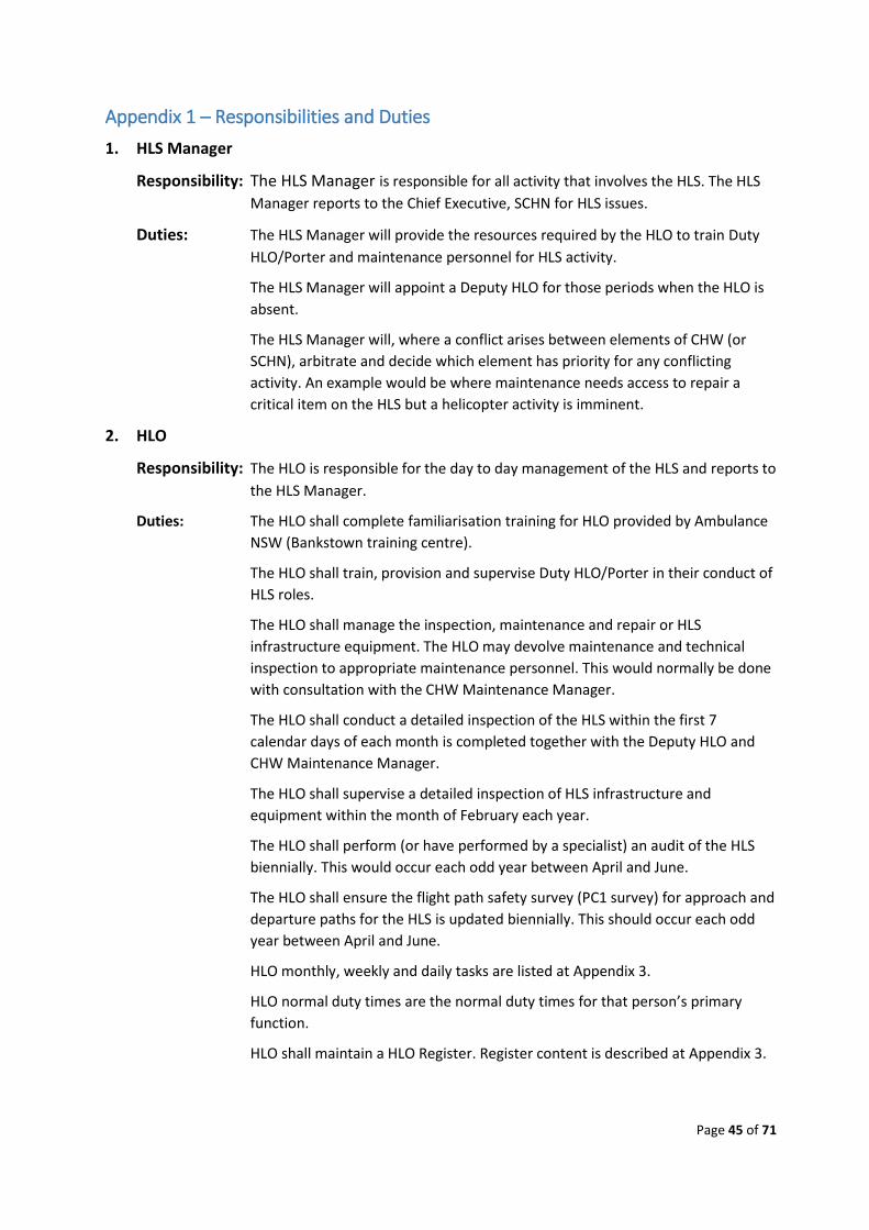
Page 45 of 71
Appendix 1 – Responsibilities and Duties
1. HLS Manager
Responsibility: The HLS Manager is responsible for all activity that involves the HLS. The HLS
Manager reports to the Chief Executive, SCHN for HLS issues.
Duties: The HLS Manager will provide the resources required by the HLO to train Duty
HLO/Porter and maintenance personnel for HLS activity.
The HLS Manager will appoint a Deputy HLO for those periods when the HLO is
absent.
The HLS Manager will, where a conflict arises between elements of CHW (or
SCHN), arbitrate and decide which element has priority for any conflicting
activity. An example would be where maintenance needs access to repair a
critical item on the HLS but a helicopter activity is imminent.
2. HLO
Responsibility: The HLO is responsible for the day to day management of the HLS and reports to
the HLS Manager.
Duties: The HLO shall complete familiarisation training for HLO provided by Ambulance
NSW (Bankstown training centre).
The HLO shall train, provision and supervise Duty HLO/Porter in their conduct of
HLS roles.
The HLO shall manage the inspection, maintenance and repair or HLS
infrastructure equipment. The HLO may devolve maintenance and technical
inspection to appropriate maintenance personnel. This would normally be done
with consultation with the CHW Maintenance Manager.
The HLO shall conduct a detailed inspection of the HLS within the first 7
calendar days of each month is completed together with the Deputy HLO and
CHW Maintenance Manager.
The HLO shall supervise a detailed inspection of HLS infrastructure and
equipment within the month of February each year.
The HLO shall perform (or have performed by a specialist) an audit of the HLS
biennially. This would occur each odd year between April and June.
The HLO shall ensure the flight path safety survey (PC1 survey) for approach and
departure paths for the HLS is updated biennially. This should occur each odd
year between April and June.
HLO monthly, weekly and daily tasks are listed at Appendix 3.
HLO normal duty times are the normal duty times for that person’s primary
function.
HLO shall maintain a HLO Register. Register content is described at Appendix 3.
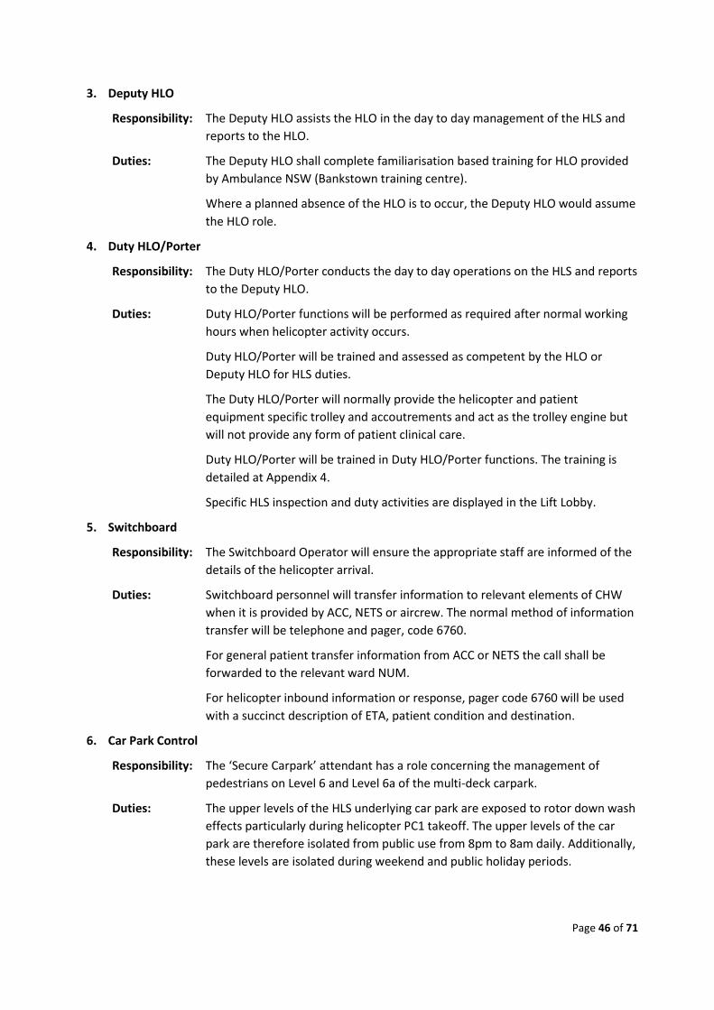
Page 46 of 71
3. Deputy HLO
Responsibility: The Deputy HLO assists the HLO in the day to day management of the HLS and
reports to the HLO.
Duties: The Deputy HLO shall complete familiarisation based training for HLO provided
by Ambulance NSW (Bankstown training centre).
Where a planned absence of the HLO is to occur, the Deputy HLO would assume
the HLO role.
4. Duty HLO/Porter
Responsibility: The Duty HLO/Porter conducts the day to day operations on the HLS and reports
to the Deputy HLO.
Duties: Duty HLO/Porter functions will be performed as required after normal working
hours when helicopter activity occurs.
Duty HLO/Porter will be trained and assessed as competent by the HLO or
Deputy HLO for HLS duties.
The Duty HLO/Porter will normally provide the helicopter and patient
equipment specific trolley and accoutrements and act as the trolley engine but
will not provide any form of patient clinical care.
Duty HLO/Porter will be trained in Duty HLO/Porter functions. The training is
detailed at Appendix 4.
Specific HLS inspection and duty activities are displayed in the Lift Lobby.
5. Switchboard
Responsibility: The Switchboard Operator will ensure the appropriate staff are informed of the
details of the helicopter arrival.
Duties: Switchboard personnel will transfer information to relevant elements of CHW
when it is provided by ACC, NETS or aircrew. The normal method of information
transfer will be telephone and pager, code 6760.
For general patient transfer information from ACC or NETS the call shall be
forwarded to the relevant ward NUM.
For helicopter inbound information or response, pager code 6760 will be used
with a succinct description of ETA, patient condition and destination.
6. Car Park Control
Responsibility: The ‘Secure Carpark’ attendant has a role concerning the management of
pedestrians on Level 6 and Level 6a of the multi-deck carpark.
Duties: The upper levels of the HLS underlying car park are exposed to rotor down wash
effects particularly during helicopter PC1 takeoff. The upper levels of the car
park are therefore isolated from public use from 8pm to 8am daily. Additionally,
these levels are isolated during weekend and public holiday periods.
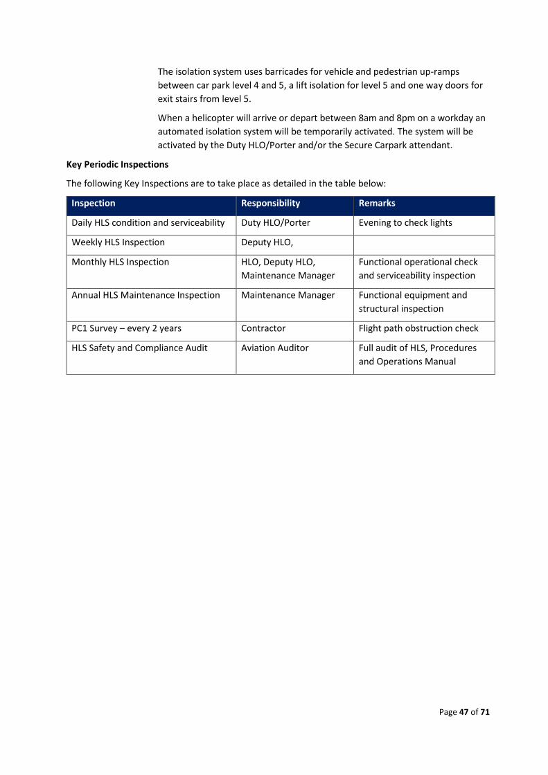
Page 47 of 71
The isolation system uses barricades for vehicle and pedestrian up-ramps
between car park level 4 and 5, a lift isolation for level 5 and one way doors for
exit stairs from level 5.
When a helicopter will arrive or depart between 8am and 8pm on a workday an
automated isolation system will be temporarily activated. The system will be
activated by the Duty HLO/Porter and/or the Secure Carpark attendant.
Key Periodic Inspections
The following Key Inspections are to take place as detailed in the table below:
Inspection Responsibility Remarks
Daily HLS condition and serviceability Duty HLO/Porter Evening to check lights
Weekly HLS Inspection Deputy HLO,
Monthly HLS Inspection HLO, Deputy HLO,
Maintenance Manager
Functional operational check
and serviceability inspection
Annual HLS Maintenance Inspection Maintenance Manager Functional equipment and
structural inspection
PC1 Survey – every 2 years Contractor Flight path obstruction check
HLS Safety and Compliance Audit Aviation Auditor Full audit of HLS, Procedures
and Operations Manual

Page 48 of 71
Appendix 2 - PC1 Survey Report
1. The PC1 Survey is yet to be completed.
Page 49 of 71
Appendix 3 – HLO Monthly, Weekly and Daily Inspection Checklists
1.0 General
1.1. The HLO conducts a monthly, weekly and daily visual inspection of the HLS
infrastructure, equipment assigned to the HLS and consumables used during HLS
operations.
1.2. Items found deficient shall be replaced, repaired or removed. Items necessary for
continued HLS operations will be replaced as soon as practical.
1.3. Critical failures may cause HLS closure. Where this eventuates the HLO shall report this
to the HLS Manager and to ACC.
1.4. All repair requests will be formally processed through the Maintenance Manager.
1.5. Daily inspections are subsumed by weekly inspections, Weekly inspections are
subsumed by monthly inspections.
1.6. Inspections checklist and instructions are shown below.
2.0 Inspection Checklists.
2.1 The Daily, Weekly and Monthly Inspection Checklists are printable double sided sheets.
3.0 HLO Register
3.1 The HLO Register is the management document for HLS controls and records. The
register normally resides at the HLO’s Office and should contain the following:
a. Part A: HLS Swipe Card Authorisation and HLS Swipe Card Issue register
b. Part B: Duty HLO/Porter HLS Checklists
c. Part C: Checklists for HLO Daily, Weekly and Monthly Inspections
d. Part D: Personnel Training Records
e. Part E: Maintenance Inspection Reports
f. Part F: Aeronautical Data Records and Forms
g. Part G: The HLO Copy of this manual.
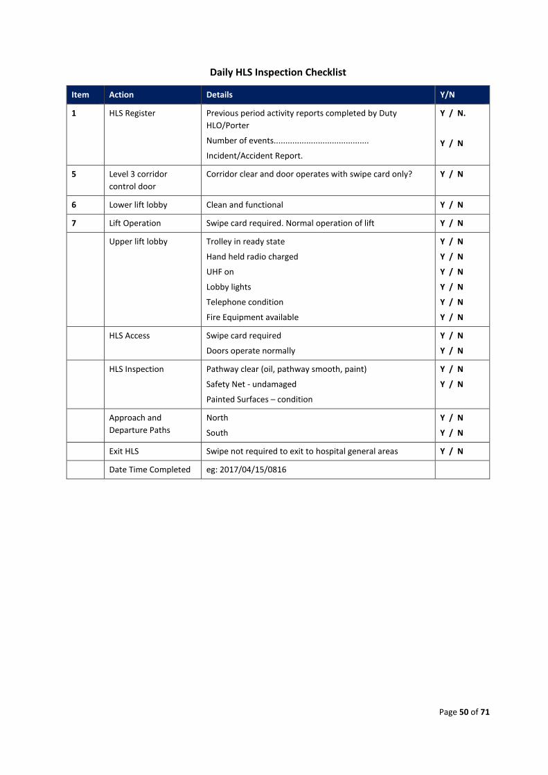
Page 50 of 71
Daily HLS Inspection Checklist
Item Action Details Y/N
1 HLS Register Previous period activity reports completed by Duty
HLO/Porter
Number of events.........................................
Incident/Accident Report.
Y / N.
Y / N
5 Level 3 corridor
control door
Corridor clear and door operates with swipe card only? Y / N
6 Lower lift lobby Clean and functional Y / N
7 Lift Operation Swipe card required. Normal operation of lift Y / N
Upper lift lobby Trolley in ready state
Hand held radio charged
UHF on
Lobby lights
Telephone condition
Fire Equipment available
Y / N
Y / N
Y / N
Y / N
Y / N
Y / N
HLS Access Swipe card required
Doors operate normally
Y / N
Y / N
HLS Inspection Pathway clear (oil, pathway smooth, paint)
Safety Net - undamaged
Painted Surfaces – condition
Y / N
Y / N
Approach and
Departure Paths
North
South
Y / N
Y / N
Exit HLS Swipe not required to exit to hospital general areas Y / N
Date Time Completed eg: 2017/04/15/0816
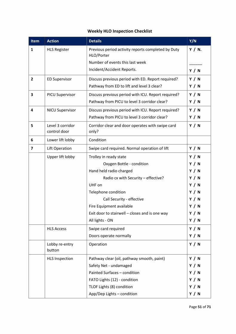
Page 51 of 71
Weekly HLO Inspection Checklist
Item Action Details Y/N
1 HLS Register Previous period activity reports completed by Duty
HLO/Porter
Number of events this last week
Incident/Accident Reports.
Y / N.
...........
Y / N
2 ED Supervisor Discuss previous period with ED. Report required?
Pathway from ED to lift and level 3 clear?
Y / N
Y / N
3 PICU Supervisor Discuss previous period with ICU. Report required?
Pathway from PICU to level 3 corridor clear?
Y / N
Y / N
4 NICU Supervisor Discuss previous period with ICU. Report required?
Pathway from PICU to level 3 corridor clear?
Y / N
Y / N
5 Level 3 corridor
control door
Corridor clear and door operates with swipe card
only?
Y / N
6 Lower lift lobby Condition
7 Lift Operation Swipe card required. Normal operation of lift Y / N
Upper lift lobby Trolley in ready state
Oxygen Bottle - condition
Hand held radio charged
Radio cx with Security – effective?
UHF on
Telephone condition
Call Security - effective
Fire Equipment available
Exit door to stairwell – closes and is one way
All lights - ON
Y / N
Y / N
Y / N
Y / N
Y / N
Y / N
Y / N
Y / N
Y / N
Y / N
HLS Access Swipe card required
Doors operate normally
Y / N
Y / N
Lobby re-entry
button
Operation Y / N
HLS Inspection Pathway clear (oil, pathway smooth, paint)
Safety Net - undamaged
Painted Surfaces – condition
FATO Lights (12) - condition
TLOF Lights (8) condition
App/Dep Lights – condition
Y / N
Y / N
Y / N
Y / N
Y / N
Y / N
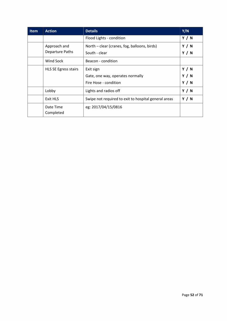
Page 52 of 71
Item Action Details Y/N
Flood Lights - condition Y / N
Approach and
Departure Paths
North – clear (cranes, fog, balloons, birds)
South - clear
Y / N
Y / N
Wind Sock Beacon - condition
HLS SE Egress stairs Exit sign
Gate, one way, operates normally
Fire Hose - condition
Y / N
Y / N
Y / N
Lobby Lights and radios off Y / N
Exit HLS Swipe not required to exit to hospital general areas Y / N
Date Time
Completed
eg: 2017/04/15/0816
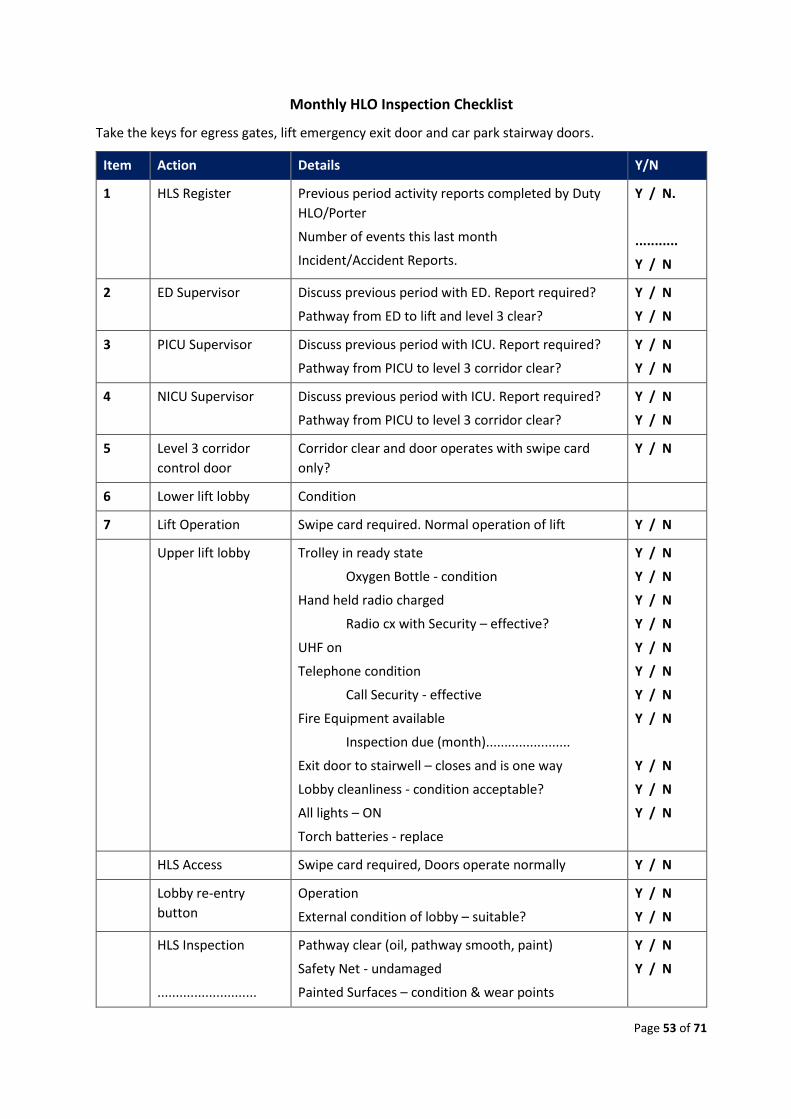
Page 53 of 71
Monthly HLO Inspection Checklist
Take the keys for egress gates, lift emergency exit door and car park stairway doors.
Item Action Details Y/N
1 HLS Register Previous period activity reports completed by Duty
HLO/Porter
Number of events this last month
Incident/Accident Reports.
Y / N.
...........
Y / N
2 ED Supervisor Discuss previous period with ED. Report required?
Pathway from ED to lift and level 3 clear?
Y / N
Y / N
3 PICU Supervisor Discuss previous period with ICU. Report required?
Pathway from PICU to level 3 corridor clear?
Y / N
Y / N
4 NICU Supervisor Discuss previous period with ICU. Report required?
Pathway from PICU to level 3 corridor clear?
Y / N
Y / N
5 Level 3 corridor
control door
Corridor clear and door operates with swipe card
only?
Y / N
6 Lower lift lobby Condition
7 Lift Operation Swipe card required. Normal operation of lift Y / N
Upper lift lobby Trolley in ready state
Oxygen Bottle - condition
Hand held radio charged
Radio cx with Security – effective?
UHF on
Telephone condition
Call Security - effective
Fire Equipment available
Inspection due (month).......................
Exit door to stairwell – closes and is one way
Lobby cleanliness - condition acceptable?
All lights – ON
Torch batteries - replace
Y / N
Y / N
Y / N
Y / N
Y / N
Y / N
Y / N
Y / N
Y / N
Y / N
Y / N
HLS Access Swipe card required, Doors operate normally Y / N
Lobby re-entry
button
Operation
External condition of lobby – suitable?
Y / N
Y / N
HLS Inspection
...........................
Pathway clear (oil, pathway smooth, paint)
Safety Net - undamaged
Painted Surfaces – condition & wear points
Y / N
Y / N
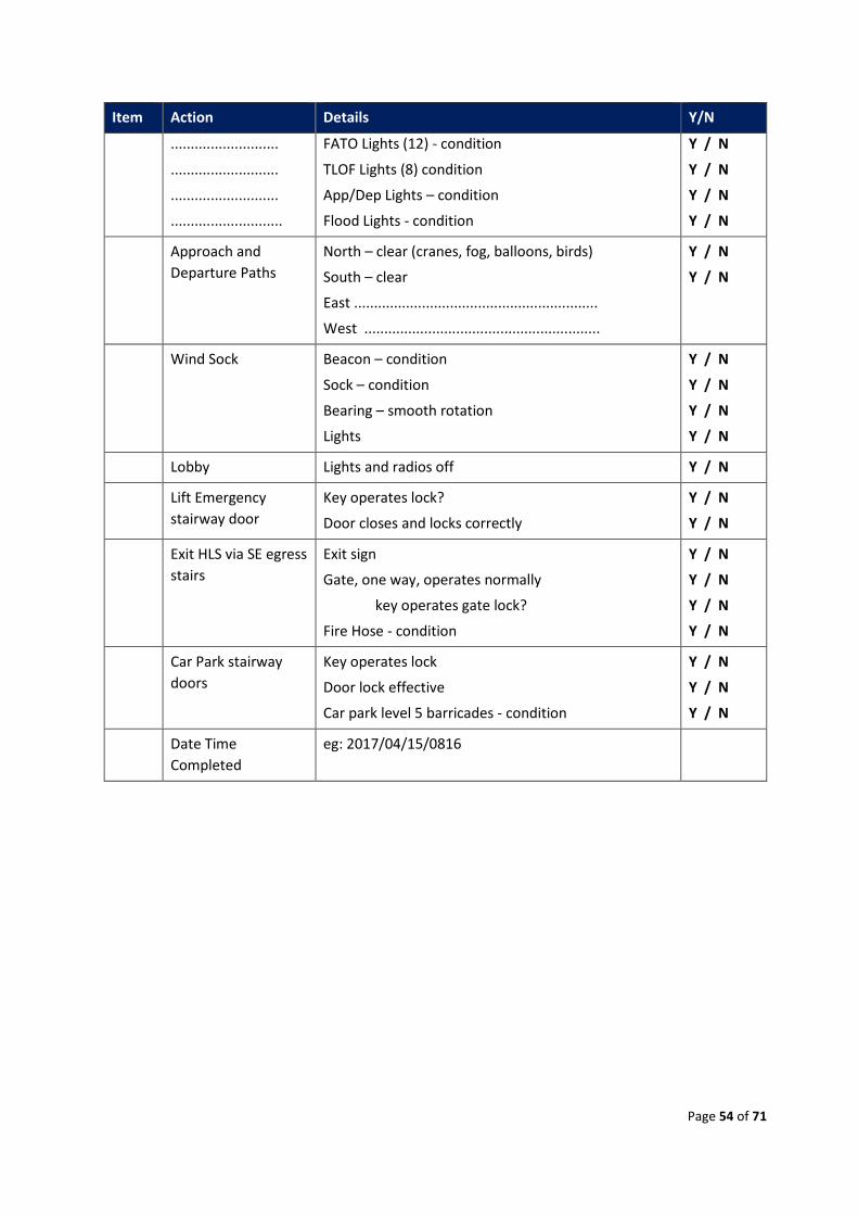
Page 54 of 71
Item Action Details Y/N
...........................
...........................
...........................
............................
FATO Lights (12) - condition
TLOF Lights (8) condition
App/Dep Lights – condition
Flood Lights - condition
Y / N
Y / N
Y / N
Y / N
Approach and
Departure Paths
North – clear (cranes, fog, balloons, birds)
South – clear
East .............................................................
West ...........................................................
Y / N
Y / N
Wind Sock Beacon – condition
Sock – condition
Bearing – smooth rotation
Lights
Y / N
Y / N
Y / N
Y / N
Lobby Lights and radios off Y / N
Lift Emergency
stairway door
Key operates lock?
Door closes and locks correctly
Y / N
Y / N
Exit HLS via SE egress
stairs
Exit sign
Gate, one way, operates normally
key operates gate lock?
Fire Hose - condition
Y / N
Y / N
Y / N
Y / N
Car Park stairway
doors
Key operates lock
Door lock effective
Car park level 5 barricades - condition
Y / N
Y / N
Y / N
Date Time
Completed
eg: 2017/04/15/0816
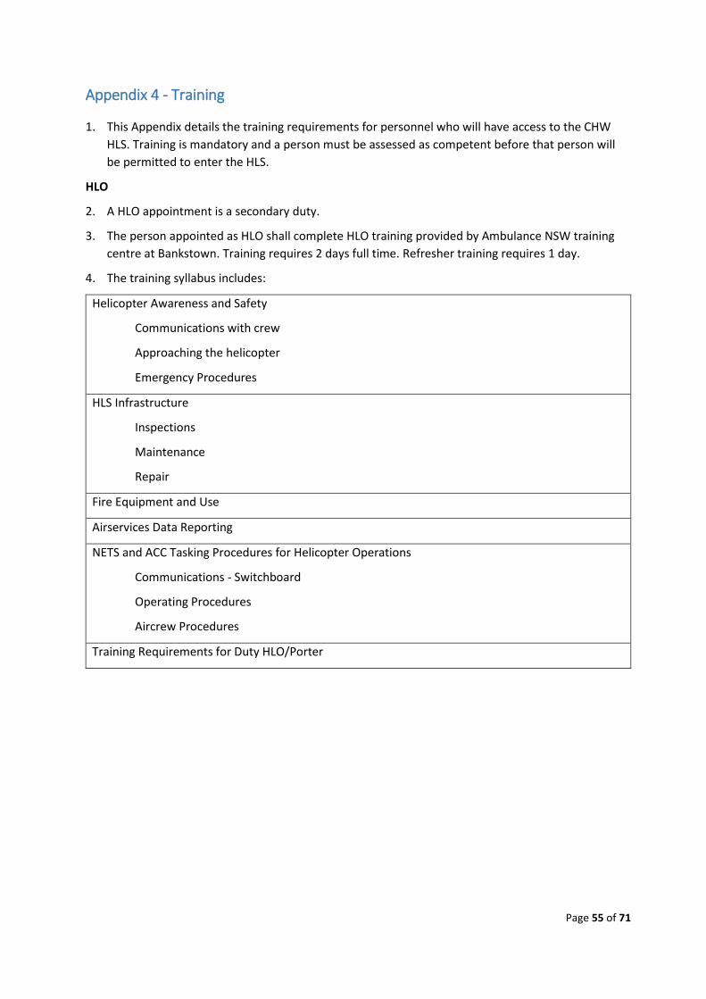
Page 55 of 71
Appendix 4 - Training
1. This Appendix details the training requirements for personnel who will have access to the CHW
HLS. Training is mandatory and a person must be assessed as competent before that person will
be permitted to enter the HLS.
HLO
2. A HLO appointment is a secondary duty.
3. The person appointed as HLO shall complete HLO training provided by Ambulance NSW training
centre at Bankstown. Training requires 2 days full time. Refresher training requires 1 day.
4. The training syllabus includes:
Helicopter Awareness and Safety
Communications with crew
Approaching the helicopter
Emergency Procedures
HLS Infrastructure
Inspections
Maintenance
Repair
Fire Equipment and Use
Airservices Data Reporting
NETS and ACC Tasking Procedures for Helicopter Operations
Communications - Switchboard
Operating Procedures
Aircrew Procedures
Training Requirements for Duty HLO/Porter
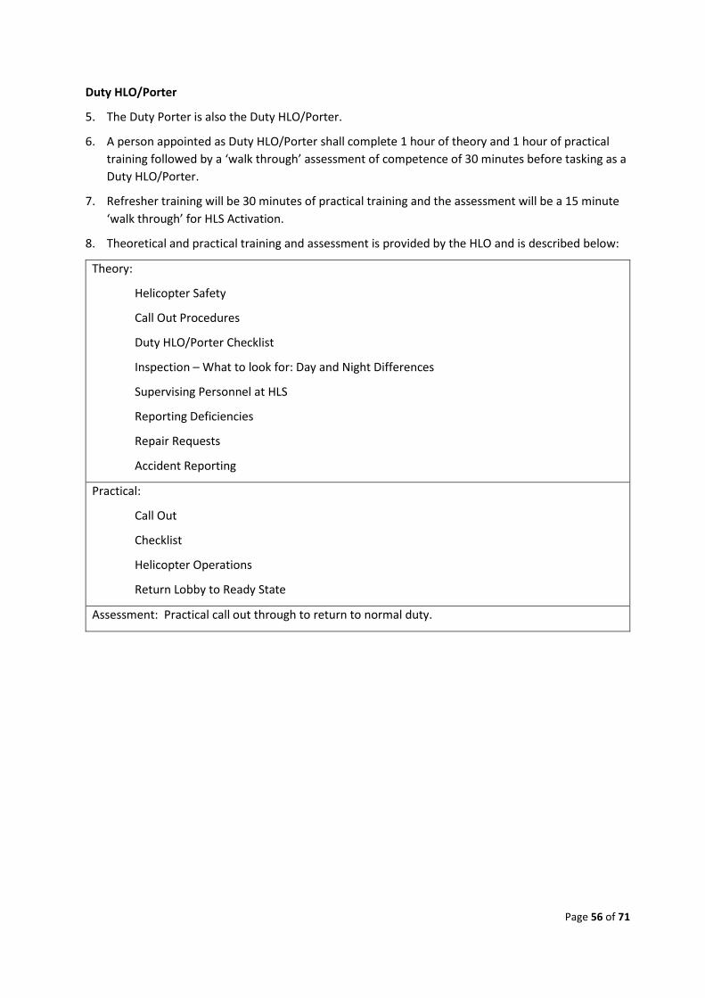
Page 56 of 71
Duty HLO/Porter
5. The Duty Porter is also the Duty HLO/Porter.
6. A person appointed as Duty HLO/Porter shall complete 1 hour of theory and 1 hour of practical
training followed by a ‘walk through’ assessment of competence of 30 minutes before tasking as a
Duty HLO/Porter.
7. Refresher training will be 30 minutes of practical training and the assessment will be a 15 minute
‘walk through’ for HLS Activation.
8. Theoretical and practical training and assessment is provided by the HLO and is described below:
Theory:
Helicopter Safety
Call Out Procedures
Duty HLO/Porter Checklist
Inspection – What to look for: Day and Night Differences
Supervising Personnel at HLS
Reporting Deficiencies
Repair Requests
Accident Reporting
Practical:
Call Out
Checklist
Helicopter Operations
Return Lobby to Ready State
Assessment: Practical call out through to return to normal duty.
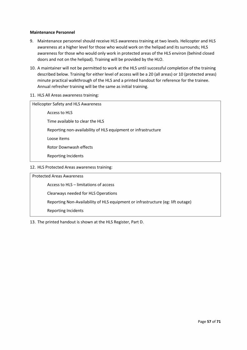
Page 57 of 71
Maintenance Personnel
9. Maintenance personnel should receive HLS awareness training at two levels. Helicopter and HLS
awareness at a higher level for those who would work on the helipad and its surrounds; HLS
awareness for those who would only work in protected areas of the HLS environ (behind closed
doors and not on the helipad). Training will be provided by the HLO.
10. A maintainer will not be permitted to work at the HLS until successful completion of the training
described below. Training for either level of access will be a 20 (all areas) or 10 (protected areas)
minute practical walkthrough of the HLS and a printed handout for reference for the trainee.
Annual refresher training will be the same as initial training.
11. HLS All Areas awareness training:
Helicopter Safety and HLS Awareness
Access to HLS
Time available to clear the HLS
Reporting non-availability of HLS equipment or infrastructure
Loose items
Rotor Downwash effects
Reporting Incidents
12. HLS Protected Areas awareness training:
Protected Areas Awareness
Access to HLS – limitations of access
Clearways needed for HLS Operations
Reporting Non-Availability of HLS equipment or infrastructure (eg: lift outage)
Reporting Incidents
13. The printed handout is shown at the HLS Register, Part D.
Page 58 of 71
Appendix 5 – Maintenance Plan
14. The Maintenance Manager and HLO will develop the Maintenance Plan for the HLS.
15. Plan to be issued by July 2017.
Page 59 of 71
Appendix 6 – Duty HLO/Porter Checklists
Duty HLO/Porter
1. A daily HLS inspection checklist is organised by the HLO during normal working hours (Mon – Fri
and at approx 8am).
2. The HLO shall determine whether the Daily HLO Inspection Checklist, as shown at Appendix 3, is to
be performed by a Duty HLO/Porter on the middle day of a long weekend.
3. When a call out is advised via pager that a helicopter is inbound the Duty HLO/Porter will be
activated. The Duty HLO/Porter shall perform HLS duty in accordance with the checklist attached
at Annex A to this Appendix.
4. The full HLS inspection list is located in the Lift Lobby.
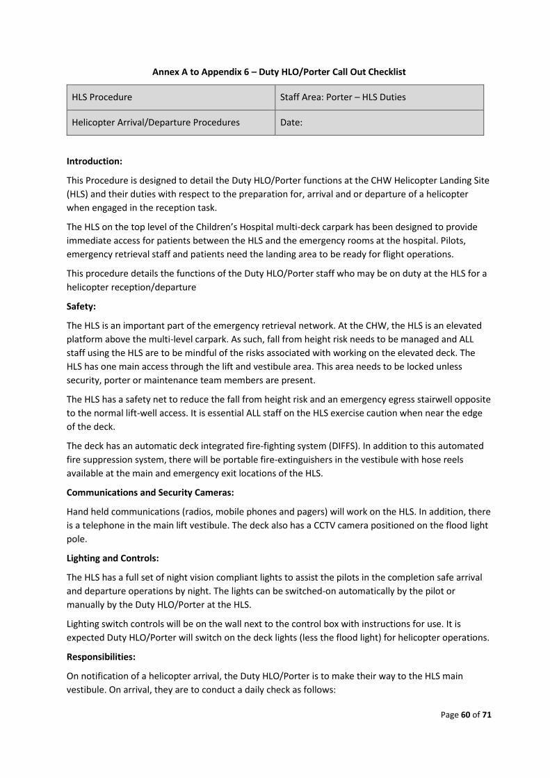
Page 60 of 71
Annex A to Appendix 6 – Duty HLO/Porter Call Out Checklist
HLS Procedure Staff Area: Porter – HLS Duties
Helicopter Arrival/Departure Procedures Date:
Introduction:
This Procedure is designed to detail the Duty HLO/Porter functions at the CHW Helicopter Landing Site
(HLS) and their duties with respect to the preparation for, arrival and or departure of a helicopter
when engaged in the reception task.
The HLS on the top level of the Children’s Hospital multi-deck carpark has been designed to provide
immediate access for patients between the HLS and the emergency rooms at the hospital. Pilots,
emergency retrieval staff and patients need the landing area to be ready for flight operations.
This procedure details the functions of the Duty HLO/Porter staff who may be on duty at the HLS for a
helicopter reception/departure
Safety:
The HLS is an important part of the emergency retrieval network. At the CHW, the HLS is an elevated
platform above the multi-level carpark. As such, fall from height risk needs to be managed and ALL
staff using the HLS are to be mindful of the risks associated with working on the elevated deck. The
HLS has one main access through the lift and vestibule area. This area needs to be locked unless
security, porter or maintenance team members are present.
The HLS has a safety net to reduce the fall from height risk and an emergency egress stairwell opposite
to the normal lift-well access. It is essential ALL staff on the HLS exercise caution when near the edge
of the deck.
The deck has an automatic deck integrated fire-fighting system (DIFFS). In addition to this automated
fire suppression system, there will be portable fire-extinguishers in the vestibule with hose reels
available at the main and emergency exit locations of the HLS.
Communications and Security Cameras:
Hand held communications (radios, mobile phones and pagers) will work on the HLS. In addition, there
is a telephone in the main lift vestibule. The deck also has a CCTV camera positioned on the flood light
pole.
Lighting and Controls:
The HLS has a full set of night vision compliant lights to assist the pilots in the completion safe arrival
and departure operations by night. The lights can be switched-on automatically by the pilot or
manually by the Duty HLO/Porter at the HLS.
Lighting switch controls will be on the wall next to the control box with instructions for use. It is
expected Duty HLO/Porter will switch on the deck lights (less the flood light) for helicopter operations.
Responsibilities:
On notification of a helicopter arrival, the Duty HLO/Porter is to make their way to the HLS main
vestibule. On arrival, they are to conduct a daily check as follows:
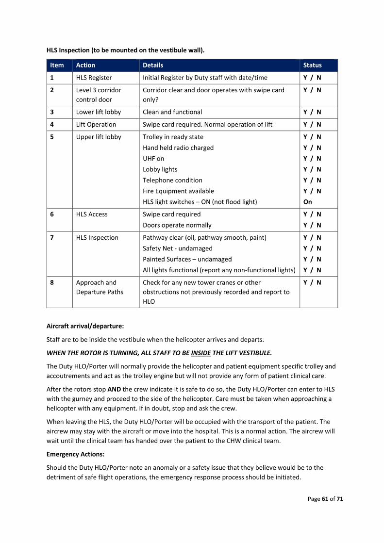
Page 61 of 71
HLS Inspection (to be mounted on the vestibule wall).
Item Action Details Status
1 HLS Register Initial Register by Duty staff with date/time Y / N
2 Level 3 corridor
control door
Corridor clear and door operates with swipe card
only?
Y / N
3 Lower lift lobby Clean and functional Y / N
4 Lift Operation Swipe card required. Normal operation of lift Y / N
5 Upper lift lobby Trolley in ready state
Hand held radio charged
UHF on
Lobby lights
Telephone condition
Fire Equipment available
HLS light switches – ON (not flood light)
Y / N
Y / N
Y / N
Y / N
Y / N
Y / N
On
6 HLS Access Swipe card required
Doors operate normally
Y / N
Y / N
7 HLS Inspection Pathway clear (oil, pathway smooth, paint)
Safety Net - undamaged
Painted Surfaces – undamaged
All lights functional (report any non-functional lights)
Y / N
Y / N
Y / N
Y / N
8 Approach and
Departure Paths
Check for any new tower cranes or other
obstructions not previously recorded and report to
HLO
Y / N
Aircraft arrival/departure:
Staff are to be inside the vestibule when the helicopter arrives and departs.
WHEN THE ROTOR IS TURNING, ALL STAFF TO BE INSIDE THE LIFT VESTIBULE.
The Duty HLO/Porter will normally provide the helicopter and patient equipment specific trolley and
accoutrements and act as the trolley engine but will not provide any form of patient clinical care.
After the rotors stop AND the crew indicate it is safe to do so, the Duty HLO/Porter can enter to HLS
with the gurney and proceed to the side of the helicopter. Care must be taken when approaching a
helicopter with any equipment. If in doubt, stop and ask the crew.
When leaving the HLS, the Duty HLO/Porter will be occupied with the transport of the patient. The
aircrew may stay with the aircraft or move into the hospital. This is a normal action. The aircrew will
wait until the clinical team has handed over the patient to the CHW clinical team.
Emergency Actions:
Should the Duty HLO/Porter note an anomaly or a safety issue that they believe would be to the
detriment of safe flight operations, the emergency response process should be initiated.

Page 62 of 71
Page 63 of 71
Appendix 7 – Aeronautical Data Forms
1. The Aeronautical Data Forms have been submitted to Air Services Australia.
2. ‘YXWM’ approval certificate to be attached.
Page 64 of 71
Appendix 8 – HLS Safety
1. The purpose of the HLS Safety Guidelines is to give a basic understanding of where the potential
dangers exist, and how to work around helicopters safely and effectively. This is a guide only and is
not a substitute for attendance at a training session to work safely around aircraft.
2. Note: Only designated LBH staff members are allowed to enter the HLS or HLS lobby at ANY time.
Only personnel trained in safe helicopter operations are allowed near the HLS during helicopter
operations.
3. When working around aircraft such as helicopters personnel MUST remain aware of the DANGERS
at ALL TIMES!
4. The procedures and cautions applied in the vicinity of a helicopter should be the same whether
the helicopter engines are running or have shut down.
Helicopter Danger Zones
5. The shape, size and behaviour of helicopters create a potentially dangerous situation, particularly
at night when visibility is reduced and in situations where the clinical needs of a patient may
distract the attention of personnel attending the helicopter.
Rotor Blades
6. The greatest threat when operating around a helicopter is the turning rotor blades.
7. The main rotor is the large one on top of the helicopter and the tail rotor is the smaller one at the
rear of the helicopter.
8. When stationary, the blades of the main rotor can droop down with a minimum clearance
approaching the height of an adult. When the rotors are turning, the high speed tail rotor is
virtually invisible. It is good practice regardless of the type of helicopter, to remove any head wear,
and bend the head down when entering or departing under a turning main rotor disk. Under no
circumstances are personnel on the deck, other than Ambulance NSW crew, to enter under the
rotor disk aft of the main cabin area.
9. Physical contact with either main or tail rotor when turning will result in serious injury or DEATH!
10. If rotors are turning, additional hazards are generated by the volume and velocity of air in the
rotor downwash, the noise generated by the rotors and the engines and the associated difficulties
for spoken communication in such circumstances.
Helicopter Shapes
11. A range of helicopter types may operate at the CHW HLS with each having different physical
characteristics. Differences relate to the use of skids or wheels, the location of protrusions such as
horizontal stabilisers from the fuselage and different locations and orientations of doors. In
general terms, helicopters can provide a number of things to trip over or bump into.
General Safety Guidelines
12. In general, it is important to remember that EVERY helicopter operation is potentially a dangerous
activity that requires the FULL attention of personnel on the HLS and/or in the helicopter.
13. Only designated and trained LBH personnel are allowed in the HLS lobby or onto the
14. HLS deck during safe helicopter operations.
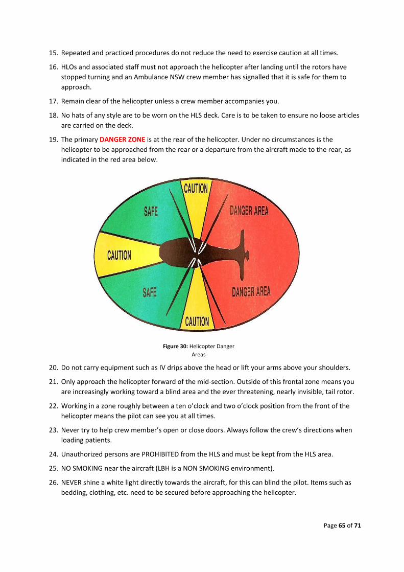
Page 65 of 71
15. Repeated and practiced procedures do not reduce the need to exercise caution at all times.
16. HLOs and associated staff must not approach the helicopter after landing until the rotors have
stopped turning and an Ambulance NSW crew member has signalled that it is safe for them to
approach.
17. Remain clear of the helicopter unless a crew member accompanies you.
18. No hats of any style are to be worn on the HLS deck. Care is to be taken to ensure no loose articles
are carried on the deck.
19. The primary DANGER ZONE is at the rear of the helicopter. Under no circumstances is the
helicopter to be approached from the rear or a departure from the aircraft made to the rear, as
indicated in the red area below.
Figure 30: Helicopter Danger
Areas
20. Do not carry equipment such as IV drips above the head or lift your arms above your shoulders.
21. Only approach the helicopter forward of the mid-section. Outside of this frontal zone means you
are increasingly working toward a blind area and the ever threatening, nearly invisible, tail rotor.
22. Working in a zone roughly between a ten o’clock and two o’clock position from the front of the
helicopter means the pilot can see you at all times.
23. Never try to help crew member’s open or close doors. Always follow the crew’s directions when
loading patients.
24. Unauthorized persons are PROHIBITED from the HLS and must be kept from the HLS area.
25. NO SMOKING near the aircraft (LBH is a NON SMOKING environment).
26. NEVER shine a white light directly towards the aircraft, for this can blind the pilot. Items such as
bedding, clothing, etc. need to be secured before approaching the helicopter.
Page 66 of 71
Appendix 9 – HLS Certification
The following HLS Certification Documents are attached to this Appendix 9:
A. Load Bearing Certification
B. NVG Lighting Compliance Certification
C. Electrical certification
D. Paint/Marking Certification
E. Fire-fighting DIFFS Compliance Certification
Page 67 of 71
Appendix 9A – HLS Load Bearing Certification
Appendix 9A Arup
Loading Bearing Certification.pdf
Page 68 of 71
Appendix 9B – HLS NVG Compliance Certification
Appendix 9B1 Point
Certificate NVG Compatability.pdf
Appendix 9B2 IEC Ex
Cert Point PRL Perimeter Light PRL-97X04-xx-x-AX-xxx Signed.pdf

Page 69 of 71
Appendix 9C – HLS Electrical Certification
Appendix 9C
General Electrical, Power and Wiring Certificate.pdf

Page 70 of 71
Appendix 9D – HLS Paint/Marking Certification
Appendix 9D
Painting Marking Certificate.pdf

Page 71 of 71
Appendix 9E – HLS Fire-fighting DIFFS Certification
Appendix 9E DIFFS
Letter from AO - 230317.pdf