the citadel department of electrical engineeringece.citadel.edu/peeples/elec 421/e-porpoise...
TRANSCRIPT
Addendum
A1
The Citadel Department of Electrical Engineering
Electric-Propelled Overboard Recovery Platform Offshore Intelligent Safety Equipment
(E-PORPOISE)
Part Number EPORPOISE-2015-0EE0
Date: 04/05/2015
Engineering Specification (ES) number: ES-001A
Engineering Change (EC) number: EC-00
Prepared by:
Approved by: ________________________ Project Designer
________________________ Project Designer
________________________ Project Designer
________________________ Project Designer
________________________ Project Designer
________________________ Faculty Advisor
________________________ Course Instructor
Classification: For Citadel Use Only

A2
TABLE OF CONTENTS
1. Scope………………………………………………………………………………………. 4
2. References………………………………………………………………………………… 4
3. Requirements……………………………………………………………………………... 4
3.1. Operations…………………………………………………………………………….. 4
3.1.1. Controls………………………………………………………………………….. 4
3.1.2. Functions………………………………………………………………………… 5
3.1.2.1. Hardware………………………………………………………………… 5
3.1.2.1.1. Beacon.…………….…………………………........................ 5
3.1.2.1.2. Fish…..………………………………………………............... 6
3.1.2.1.3. Bill of Materials…….………………………………………….. 8
3.1.2.2. Software…………………………………………………………………. 8
3.1.2.2.1. Description…………………………………………………….. 8
3.1.2.2.2. Optimization…………………………………………………... 9
3.1.2.2.3. Flowcharts…………………………………………………….. 11
3.1.3. Calibration………………………………………………………………………. 12
3.2. Interfaces……………………………………………………………………………… 12
3.2.1. Power……………………………………………………………………………. 12
3.2.1.1. Electrical………………………………………………………………… 12
3.2.1.2. Mechanical……………………………………………………………… 13
3.2.2. Wired Data……………………………………………………………………… 14
3.2.3. Wireless Data…………………………………………………………………... 15
3.3. Physical Dimensions…………………………………………………………………. 15
3.3.1. Size………………………………………………………………………………. 15
3.3.2. Weight……………………………………………………………………………. 16
3.4. Environmental………………………………………………………………………… 17
3.5. Materials………………………………………………………………………………. 17
3.6. Assembly………………………………………………………………………………. 18
3.7. Safety………………………………………………………………………………….. 18
4. Testing…………………………………………………………………………………….. 18
4.1. Constraints……………………………………………………………………………. 18

A3
4.2. Location……………………………………………………………………………….. 18
4.3. Procedure……………………………………………………………………………… 18
5. Reliability…………………………………………………………………………………… 19
6. Appendices………………………………………………………………………………… 19

A4
1. Scope
This specification establishes the electrical and mechanical requirements for the development of the Electric-Propelled Overboard Recovery Platform Offshore Intelligent Safety Equipment (E-PORPOISE). The intent of this specification is to provide technical information on the design of the E-PORPOISE, user interface, and all subsystems therein. E-PORPOISE consists of two main components, the Beacon and the Fish. The Beacon (Figure 1.a) is a user worn apparatus that utilizes a microcontroller to acquire and transmit its Global Positioning System (GPS) coordinates to the Fish via XBee®. The Fish (Figure 1.b) is a radio-controlled boat chassis that has been modified to be controlled via an onboard computer using GPS and Inertial Measurement Unit (IMU) data. The Electric-Test Operations Rig, Terrestrially Oriented, Intelligent Safety Equipment (E-TORTOISE) platform replaces the Fish during ground testing of the E-PORPOISE system. The E-TORTOISE is a four-wheeled skid steering platform that uses the same control equipment as the Fish.
2. References ● Federal Communications Commission (FCC): http://www.fcc.gov ● International Organization for Standardization (ISO):
http://www.iso.org/iso/home/standards.htm ● International Electrotechnical Commission (IEC):
http://www.iec.ch/about/activities/standards.htm?ref=home ● IEEE Standards Association: https://standards.ieee.org ● Restriction of Hazardous Substance Directive (RoHS):
http://ec.europa.eu/enterprise/policies/european-standards/harmonised-standards/restriction-of-hazardous-substances/index_en.htm
● US Coast Guard Standards Electrical: http://www.gpo.gov/fdsys/pkg/CFR-1999-title46-vol1/content-detail.html
● Global Positioning Systems Standards: http://www.gps.gov/technical/ps/
3. Requirements
3.1. Operations
3.1.1. Controls
The E-PORPOISE system has minimal accessible controls. User interface on the Fish is limited to two power switches, one to energize the onboard computer (SW1) and the other the motor-driver circuit (SW2). The Beacon has a power switch (SW3) and the Victim Actuated Pushbutton (VAP). The power switch applies voltage to the Beacon’s microcontroller. The VAP serves two functions, the first being to send a distress signal and activate the system and the second is to stop system response to a distress signal.

A5
3.1.2. Functions
3.1.2.1. Hardware
3.1.2.1.1. Beacon
As seen in Figure 1.a, SW3 passes 5VDC power to an Arduino® Uno board which interfaces an Atmel ATMega328 8-bit microcontroller with digital and analog input/ output ports, a 16MHz ceramic resonator, a USB connection, a power jack, an in-circuit serial programming (ICSP) header, and a reset button. A GPS locator circuit and XBee® serial receiver/transmitter circuit are then powered from this battery through the Arduino®. The Arduino’s® USB is equipped with a resettable 500mA polyfuse. The GlobalTop Technology FGPMMOPA6H GPS locator is a 66-channel module with a resolution radius of 3m and a warm refresh rate of 1-10Hz. In addition, the GPS shield can store up to 16hr of location data. Initial location acquisition is determined within 34s of powering on. The Digi XBee® series 1 wireless serial transmitter receiver is a Class 1 wireless device with a range of up to 100m and a data transfer rate of 250kbps. A 2600 mAh Lithium Ion battery provides 5VDC to the Arduino®. The Beacon battery is rated for 500 cycles.
The VAP applies a logic signal to the Arduino® and is the primary user interface with the E-PORPOISE system.
Figure 1.a – Level 1 Diagram, Beacon

A6
3.1.2.1.2. Fish
As seen in Figure 1.b, SW1 applies 5V DC power from a 12000mAh LiPo battery pack to a Raspberry Pi. In turn, the Raspberry Pi delivers this power to a GPS locator circuit as well as an XBee® serial receiver/transmitter circuit, two Arduino® UNO microcontrollers, and an IMU. This GPS locator is the same as that of the Beacon. The XBee® series 1 wireless serial transmitter receiver is a Class 1 wireless device with a range of up to 100m and a data transfer rate of 250kbps. An IMU that consists of a 3-axis digital magnetometer, accelerometer, and gyroscope is connected to the second Arduino® UNO via I2C to provide the Fish with an absolute bearing for magnetic north through a serial connection with the Raspberry Pi.
SW2 applies 7.2V DC power from an 1800mAh NiCd battery to dual H-bridge motor driver circuits. The H-bridge receives pulse-width modulated (PWM) control signals from the motor drive Arduino® UNO. These control signals determine the effective voltage being applied from the H-bridge circuit to the Fish’s drive motors. The relative difference in speed between the port and starboard motors steers the Fish, while the general magnitude of the voltage determines the overall speed. The H-bridge circuit is rated for 5V-26V and up to 2A per motor.
Figure 1.b – Level 1 Diagram, Fish
The Fish chassis is made from a modified RC boat hull and associated drive train (motors and propellers). The hull is made of LEXAN Polycarbonate material and has a displacement of approximately 7.25kg. The Fish uses two RS-380PH-4045 carbon-brush water-cooled DC motors. Each motor has a rated output of 0.9W-45W with a no-load

A7
speed of 12,500rpm. The motors are rated for 3-12VDC and operate between 0.56A and 3.75A. Due to a stall current of 18A, overcurrent protection will be provided by two (one per motor) 250V, 2A, fast-acting inline fuses in order to protect the H-bridge circuit. These fuses will also limit the operation of the motors to less than 28.8W total.
The E-TORTOISE chassis is constructed from welded aluminum and uses four RS-385SH-2270 carbon-brush DC motors connected to the wheels via gear assemblies to increase the drive torque. To power the additional two motors, the E-TORTOISE is equipped with an additional H-Bridge of the same design and uses a 12V 9000mAh sealed lead-acid battery. Each motor has a rated output of 0.9W-22W with a no-load speed of 10,000rpm. The motors are rated for 6-24VDC and operate between 0.20A and 0.89A. The stall current of each motor is 4A, which can be sustained safely by the motor control circuitry for a short period of time.
Figure 1.c – Level 1 Diagram, E-TORTOISE
A8
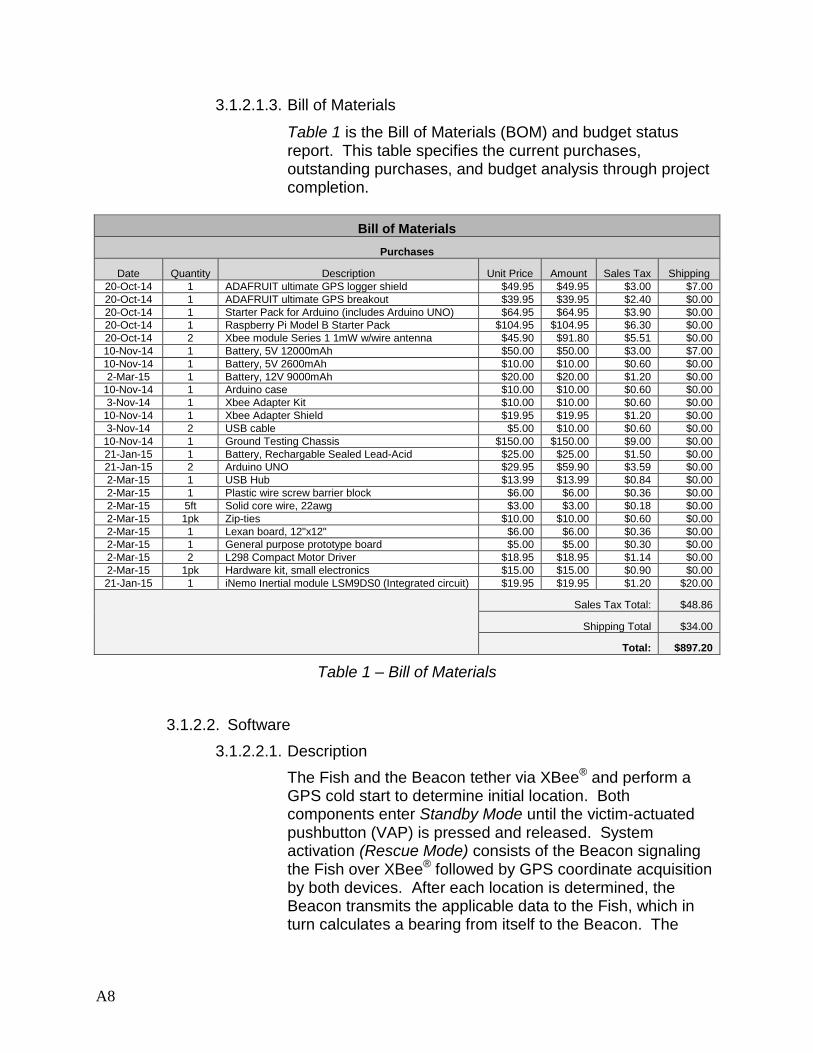
3.1.2.1.3. Bill of Materials
Table 1 is the Bill of Materials (BOM) and budget status report. This table specifies the current purchases, outstanding purchases, and budget analysis through project completion.
Bill of Materials
Purchases
Date Quantity Description Unit Price Amount Sales Tax Shipping
20-Oct-14 1 ADAFRUIT ultimate GPS logger shield $49.95 $49.95 $3.00 $7.00
20-Oct-14 1 ADAFRUIT ultimate GPS breakout $39.95 $39.95 $2.40 $0.00
20-Oct-14 1 Starter Pack for Arduino (includes Arduino UNO) $64.95 $64.95 $3.90 $0.00
20-Oct-14 1 Raspberry Pi Model B Starter Pack $104.95 $104.95 $6.30 $0.00
20-Oct-14 2 Xbee module Series 1 1mW w/wire antenna $45.90 $91.80 $5.51 $0.00
10-Nov-14 1 Battery, 5V 12000mAh $50.00 $50.00 $3.00 $7.00
10-Nov-14 1 Battery, 5V 2600mAh $10.00 $10.00 $0.60 $0.00
2-Mar-15 1 Battery, 12V 9000mAh $20.00 $20.00 $1.20 $0.00
10-Nov-14 1 Arduino case $10.00 $10.00 $0.60 $0.00
3-Nov-14 1 Xbee Adapter Kit $10.00 $10.00 $0.60 $0.00
10-Nov-14 1 Xbee Adapter Shield $19.95 $19.95 $1.20 $0.00
3-Nov-14 2 USB cable $5.00 $10.00 $0.60 $0.00
10-Nov-14 1 Ground Testing Chassis $150.00 $150.00 $9.00 $0.00
21-Jan-15 1 Battery, Rechargable Sealed Lead-Acid $25.00 $25.00 $1.50 $0.00
21-Jan-15 2 Arduino UNO $29.95 $59.90 $3.59 $0.00
2-Mar-15 1 USB Hub $13.99 $13.99 $0.84 $0.00
2-Mar-15 1 Plastic wire screw barrier block $6.00 $6.00 $0.36 $0.00
2-Mar-15 5ft Solid core wire, 22awg $3.00 $3.00 $0.18 $0.00
2-Mar-15 1pk Zip-ties $10.00 $10.00 $0.60 $0.00
2-Mar-15 1 Lexan board, 12"x12" $6.00 $6.00 $0.36 $0.00
2-Mar-15 1 General purpose prototype board $5.00 $5.00 $0.30 $0.00
2-Mar-15 2 L298 Compact Motor Driver $18.95 $18.95 $1.14 $0.00
2-Mar-15 1pk Hardware kit, small electronics $15.00 $15.00 $0.90 $0.00
21-Jan-15 1 iNemo Inertial module LSM9DS0 (Integrated circuit) $19.95 $19.95 $1.20 $20.00
Sales Tax Total: $48.86
Shipping Total $34.00
Total: $897.20
Table 1 – Bill of Materials
3.1.2.2. Software
3.1.2.2.1. Description
The Fish and the Beacon tether via XBee® and perform a GPS cold start to determine initial location. Both components enter Standby Mode until the victim-actuated pushbutton (VAP) is pressed and released. System activation (Rescue Mode) consists of the Beacon signaling the Fish over XBee® followed by GPS coordinate acquisition by both devices. After each location is determined, the Beacon transmits the applicable data to the Fish, which in turn calculates a bearing from itself to the Beacon. The

A9
calculated bearing is used as an input into the motor control subsystem in order to drive the Fish to the Beacon.
This cycle continues until the VAP is depressed and held for five seconds or the Fish drives within five meters of the Beacon (Hold Mode). In the first event the Fish stops and the system returns to Standby Mode. In Hold Mode the GPS data and bearing calculation cycle continues, but the Fish stops unless the distance between it and the Beacon increases to be greater than five meters, at which point the system returns to Rescue Mode.
3.1.2.2.2. Optimization
Software filters are used to digitally smooth the inherent noise from the inertial movement sensor as well as to choose the best possible GPS coordinate set. A speed-precision inverse relationship is presented and the ideal configuration has been obtained through extensive testing.
The GPS utilizes a rolling median filter to ensure data confidence. Five GPS-NMEA GPRMC (Minimum Recommended Data) strings are acquired and sorted to obtain the median latitude, longitude, and bearings of the data sets. The median data is then used for course determination. The GPS module is set at start-up to a location fix acquisition rate of 10Hz. Through the use of the median filter and data acquisition rate, the GPS speed-precision relationship is as follows:
𝑓𝑟𝑒𝑞𝑢𝑒𝑛𝑐𝑦 𝑜𝑓 𝐺𝑃𝑆 (𝐻𝑍)
# 𝑜𝑓 𝑠𝑎𝑚𝑝𝑙𝑒𝑠 𝑠𝑡𝑜𝑟𝑒𝑑= 𝑎𝑐𝑡𝑢𝑎𝑙 𝑓𝑟𝑒𝑞𝑢𝑒𝑛𝑐𝑦 →
10𝐻𝑧
5= 2𝐻𝑧
The IMU sensor utilizes a cumulative sum-rolling median hybrid filter (Figures 2.a and b). Seven samples from each axis of the magnetometer and accelerometer are stored in the controlling Arduino® UNO (one axis at a time) and sorted to determine the median. Three medians from each sample are then again stored and averaged. The resulting data is used to tilt-compensate magnetic bearing calculations. The refresh rate of the sensor is set to 50Hz at start-up, resulting in a bearing determination rate of:
𝑓𝑟𝑒𝑞𝑢𝑒𝑛𝑐𝑦 𝑜𝑓 𝐼𝑀𝑈 (𝐻𝑍)
# 𝑜𝑓 𝑠𝑎𝑚𝑝𝑙𝑒𝑠 𝑠𝑡𝑜𝑟𝑒𝑑= 𝑎𝑐𝑡𝑢𝑎𝑙 𝑓𝑟𝑒𝑞𝑢𝑒𝑛𝑐𝑦 →
50𝐻𝑧
3∗7+3= 2.08𝐻𝑧

A10
Figure 2.a – Magnetometer Filtering
Figure 2.b – Accelerometer Filtering
1880
1885
1890
1895
1900
1905
1910
1915
1920
1925
0 20 40 60 80 100 120 140 160 180 200 220 240 260 280 300
Va
lue
Sample
Magnetometer X-Axis Unfiltered vs Filtered
Unfiltered x
Filtered x
4920
4940
4960
4980
5000
5020
5040
0 50 100 150 200 250 300
Va
lue
Sample
Accelerometer Z-Axis Unfiltered vs Filtered
unfiltered z
filtered z
A11
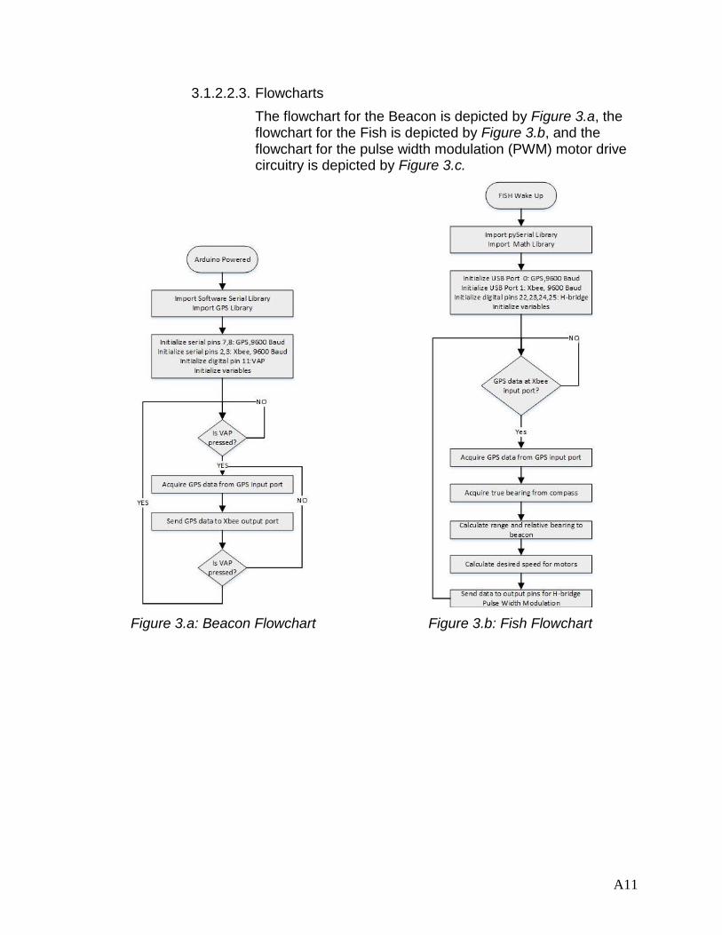
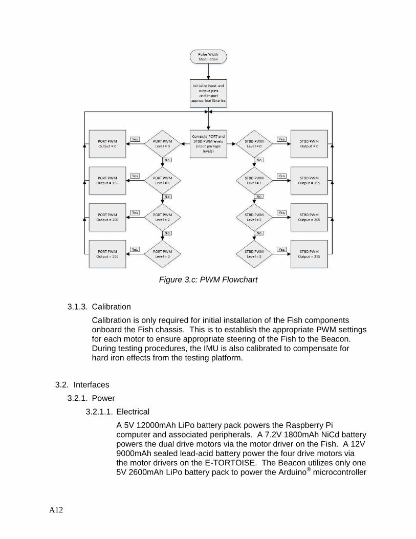
3.1.2.2.3. Flowcharts
The flowchart for the Beacon is depicted by Figure 3.a, the flowchart for the Fish is depicted by Figure 3.b, and the flowchart for the pulse width modulation (PWM) motor drive circuitry is depicted by Figure 3.c.
Figure 3.a: Beacon Flowchart Figure 3.b: Fish Flowchart
A12
Figure 3.c: PWM Flowchart
3.1.3. Calibration
Calibration is only required for initial installation of the Fish components onboard the Fish chassis. This is to establish the appropriate PWM settings for each motor to ensure appropriate steering of the Fish to the Beacon. During testing procedures, the IMU is also calibrated to compensate for hard iron effects from the testing platform.
3.2. Interfaces
3.2.1. Power
3.2.1.1. Electrical
A 5V 12000mAh LiPo battery pack powers the Raspberry Pi computer and associated peripherals. A 7.2V 1800mAh NiCd battery powers the dual drive motors via the motor driver on the Fish. A 12V 9000mAh sealed lead-acid battery power the four drive motors via the motor drivers on the E-TORTOISE. The Beacon utilizes only one 5V 2600mAh LiPo battery pack to power the Arduino® microcontroller

A13
and connected circuits. Both the Raspberry Pi and Arduino® have built-in 5V and 3.3V voltage regulators.
3.2.1.2. Mechanical
For the Fish, each drive motor has the following characteristic curves depicted in Figure 4.a while operating at 6V. To prevent an overcurrent condition in the motor drive circuit the motors will not be operated above 10mNm (corresponding to 2A).
Figure 4.a – Drive Motor Characteristic Curves, Fish
For the E-TORTOISE, each drive motor has the following characteristic curves depicted in Figure 4.b while operating at 12V. To prevent an overcurrent condition in the motor drive circuit the motors will not be operated above 20mNm (corresponding to 2A). Overload protection is provided by a built in thermal overload switch onboard the H-bridge.
Figure 4.b – Drive Motor Characteristic Curves, E-TORTOISE

A14
3.2.2. Wired Data
Specific pinout interface between the Arduino® and connected circuits is depicted in Figure 5.a. Each shield’s numbered pins are connected to the other shields at the same pins. The Arduino® receives location data from the GPS locator circuit for decoding. It also transmits and receives data to and from the XBee® module for the purposes listed under section 3.2.3. The Arduino® receives a signal from the VAP for the purpose of system activation/deactivation.
Figure 5.a: Beacon Pinout
Specific pinout interface between the Raspberry Pi and peripherals is depicted in Figure 5.b. The Raspberry Pi receives location data from the GPS locator circuit for decoding. It also transmits and receives data to and from the XBee® module for the purposes listed under section 3.2.3 (Wireless Data). The motor drive circuit receives two directional inputs, and a PWM enable input from the Raspberry Pi through an Arduino® UNO.
Figure 5.b: Fish Pinout

A15
3.2.3. Wireless Data
The Fish and the Beacon will communicate using XBee® wireless serial communication protocol (IEEE 802.15.4). The data that will be passed includes that required for initial connection, the distress signal that initiates system response, GPS coordinates from the Beacon to the Fish, and a system stop command from the Fish to the Beacon.
3.3. Physical Dimensions
3.3.1. Size (length x width x height; units: cm)
The Beacon’s overall dimensions are 14.8 x 11.0 x 9.1. Components of the Beacon measure as follows:
Arduino® Uno – 7.5 x 5.3 x 1.5
XBee® series 1 shield – 6.9 x 5.0 x 3.0
GPS locator shield – 6.9 x 5.3 x 0.7
LiPo battery pack – 9.4 x 2.2 x 2.3
All components of the Fish are encompassed by the hull of the modified RC powerboat with dimensions 80.0 x 25.0 x 21.0 in a standard sweeping V-shape. Components of the Fish measure as follows:
Raspberry Pi – 8.6 x 5.6 x 2.5
XBee® series 1 circuit – 2.4 x 2.8 x 3.0
GPS locator circuit – 2.5 x 3.4 x 0.6
H-bridge circuit – 4.0 x 4.0 x 2.5
Each drive motor – 5.8 x 3.0 x 3.0
LiPo battery pack – 9.4 x 2.2 x 2.3
NiCd battery – 19.8 x 5.0 x 2.5
For land testing all components of the Fish are inside the hardware tray of the E-TORTOISE with the exception of the IMU and XBee® modules, which are outside of the tray to reduce noise and interference. The E-TORTOISE chassis has dimensions of 72.4 x 45.1 x 68.1. The E-TORTOISE motor battery measures 12.1 x 26.8 x 11.0.
A16
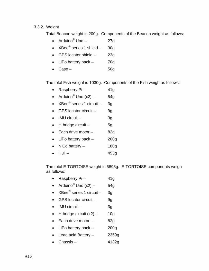
3.3.2. Weight
Total Beacon weight is 200g. Components of the Beacon weight as follows:
Arduino® Uno – 27g
XBee® series 1 shield – 30g
GPS locator shield – 23g
LiPo battery pack – 70g
Case – 50g
The total Fish weight is 1030g. Components of the Fish weigh as follows:
Raspberry Pi – 41g
Arduino® Uno (x2) – 54g
XBee® series 1 circuit – 3g
GPS locator circuit – 9g
IMU circuit – 3g
H-bridge circuit – 5g
Each drive motor – 82g
LiPo battery pack – 200g
NiCd battery – 180g
Hull – 453g
The total E-TORTOISE weight is 6893g. E-TORTOISE components weigh as follows:
Raspberry Pi – 41g
Arduino® Uno (x2) – 54g
XBee® series 1 circuit – 3g
GPS locator circuit – 9g
IMU circuit – 3g
H-bridge circuit (x2) – 10g
Each drive motor – 82g
LiPo battery pack – 200g
Lead acid Battery – 2359g
Chassis – 4132g
A17
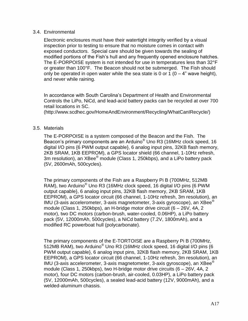
3.4. Environmental
Electronic enclosures must have their watertight integrity verified by a visual inspection prior to testing to ensure that no moisture comes in contact with exposed conductors. Special care should be given towards the sealing of modified portions of the Fish’s hull and any frequently opened enclosure hatches. The E-PORPOISE system is not intended for use in temperatures less than 32°F or greater than 100°F. The Beacon should not be submerged. The Fish should only be operated in open water while the sea state is 0 or 1 (0 – 4” wave height), and never while raining.
In accordance with South Carolina’s Department of Health and Environmental Controls the LiPo, NiCd, and lead-acid battery packs can be recycled at over 700 retail locations in SC. (http://www.scdhec.gov/HomeAndEnvironment/Recycling/WhatCanIRecycle/)
3.5. Materials
The E-PORPOISE is a system composed of the Beacon and the Fish. The Beacon’s primary components are an Arduino® Uno R3 (16MHz clock speed, 16 digital I/O pins {6 PWM output capable}, 6 analog input pins, 32KB flash memory, 2KB SRAM, 1KB EEPROM), a GPS locator shield (66 channel, 1-10Hz refresh, 3m resolution), an XBee® module (Class 1, 250kbps), and a LiPo battery pack (5V, 2600mAh, 500cycles).
The primary components of the Fish are a Raspberry Pi B (700MHz, 512MB RAM), two Arduino® Uno R3 (16MHz clock speed, 16 digital I/O pins {6 PWM output capable}, 6 analog input pins, 32KB flash memory, 2KB SRAM, 1KB EEPROM), a GPS locator circuit (66 channel, 1-10Hz refresh, 3m resolution), an IMU (3-axis accelerometer, 3-axis magnetometer, 3-axis gyroscope), an XBee® module (Class 1, 250kbps), an H-bridge motor drive circuit (6 – 26V, 4A, 2 motor), two DC motors (carbon-brush, water-cooled, 0.06HP), a LiPo battery pack (5V, 12000mAh, 500cycles), a NiCd battery (7.2V, 1800mAh), and a modified RC powerboat hull (polycarbonate).
The primary components of the E-TORTOISE are a Raspberry Pi B (700MHz, 512MB RAM), two Arduino® Uno R3 (16MHz clock speed, 16 digital I/O pins {6 PWM output capable}, 6 analog input pins, 32KB flash memory, 2KB SRAM, 1KB EEPROM), a GPS locator circuit (66 channel, 1-10Hz refresh, 3m resolution), an IMU (3-axis accelerometer, 3-axis magnetometer, 3-axis gyroscope), an XBee® module (Class 1, 250kbps), two H-bridge motor drive circuits (6 – 26V, 4A, 2 motor), four DC motors (carbon-brush, air-cooled, 0.03HP), a LiPo battery pack (5V, 12000mAh, 500cycles), a sealed lead-acid battery (12V, 9000mAh), and a welded-aluminum chassis.

A18
3.6. Assembly
All components of the Beacon are assembled in an open frame aluminum case. All components of the Fish are assembled within the watertight compartment of a modified RC powerboat hull. All components of the E-TORTOISE with the exception of the IMU and XBee® modules are assembled inside the hardware tray on the E-TORTOISE chassis.
3.7. Safety
In order to prevent damage to equipment or shock to a user the system should not be opened while waterborne, and should always be inspected for watertight integrity prior to being placed in or around water. To ensure proper system operation do not use in water with waves greater than 4” in height. To prevent injury from collision, no more than one person should be in the water with the Fish at a time, and the only person in the water should have custody of the Beacon. The Beacon user should be wearing at least a Type III PFD while testing the system in water greater than shoulder height. Do not operate the system in open water with strong current. Never test or operate the system in foul weather.
4. Testing
4.1. Constraints
E-PORPOISE is designed to have the Fish deliver itself to within 5m of the Beacon in less than 10min after the VAP has been pressed while the Fish and Beacon are separated by 30m.
4.2. Location
A large flat field free of overhead obstruction is required to simulate open water using the E-TORTOISE.
4.3. Procedure
Power on the Beacon and Fish to place the E-PORPOISE system in Standby Mode. Press and release the VAP to place the system into Rescue Mode. If the Fish closes within 5m of the Beacon, the system will automatically enter Hold Mode. Subsequent drift outside of 5m between the Fish and Beacon will automatically reengage Rescue Mode. While in Rescue Mode or Hold Mode pressing and holding the VAP for 5sec or longer will cancel system response and return the system to Standby Mode. A loss and subsequent return of power to the Fish will return the system to the mode of operation the Beacon is in. A loss and subsequent return of power to the Beacon will place the system in Standby Mode.

A19
5. Reliability
Data confidence filters are used to ensure reasonable reliability in GPS fixes. To ensure fluctuations in battery voltage during motor starting surges at low battery charge conditions do not adversely affect processor operation, all processors on the Fish are powered from a separate battery.
6. Appendices
Flying Fish II RC Boat
Web Page: https://www.hobbywarehouse.com.au/double-horse-7007-superlative-rc-speed-boat.html
Datasheet (motors): http://www.mabuchi-motor.co.jp/cgi-bin/catalog/e_catalog.cgi?CAT_ID=rs_380ph
Arduino® Uno R3
Web Page: http://arduino.cc/en/Main/ArduinoBoardUno
Raspberry Pi Model B
Web Page: http://www.adafruit.com/products/1914
ADAFRUIT ultimate GPS logger shield
Web Page: http://www.adafruit.com/product/1272
ADAFRUIT ultimate GPS breakout
Web Page: http://www.adafruit.com/product/746
Datasheet: http://www.adafruit.com/datasheets/GlobalTop-FGPMMOPA6H-Datasheet-V0A.pdf
ST LSM9DS0 iNemo Inertial Module (IMU)
Web Page: http://www.st.com/web/en/catalog
Datasheet: http://www.st.com/web/en/catalog/sense_power/FM89/SC1448/PF258556

A20
XBee® Series 1 wireless serial transmitter/receiver
Web Page: http://www.digi.com/products/wireless-wired-embedded-solutions/zigbee-rf-modules/point-multipoint-rfmodules/xbee-series1-module#overview
Datasheet: http://www.digi.com/pdf/ds_xbeemultipointmodules.pdf
H-Bridge motor driver circuit
Web Page: https://solarbotics.com/product/k_cmd/
Datasheet: https://solarbotics.com/download.php?file=40
LiPo battery pack
Web Page: http://www.szshengyi.net
Datasheet: http://www.szshengyi.net/e_productshow/?23-lipsick-power-bank-23.html
NiCd battery
Web Page: http://www.globesmall.com
Datasheet: http://www.globesmall.com/product/242800
Sealed lead-acid battery
Web Page: http://www.yuasabatteries.com/np_industrial.php
Datasheet: http://www.yuasabatteries.com/pdfs/NP_7_12_DataSheet.pdf